Qisda GW52 MOD-SM QIS BT/WLAN CWM-02B-BT2-SP D5 User Manual
Qisda Corporation MOD-SM QIS BT/WLAN CWM-02B-BT2-SP D5
UserManual.wiki
>
Qisda
>
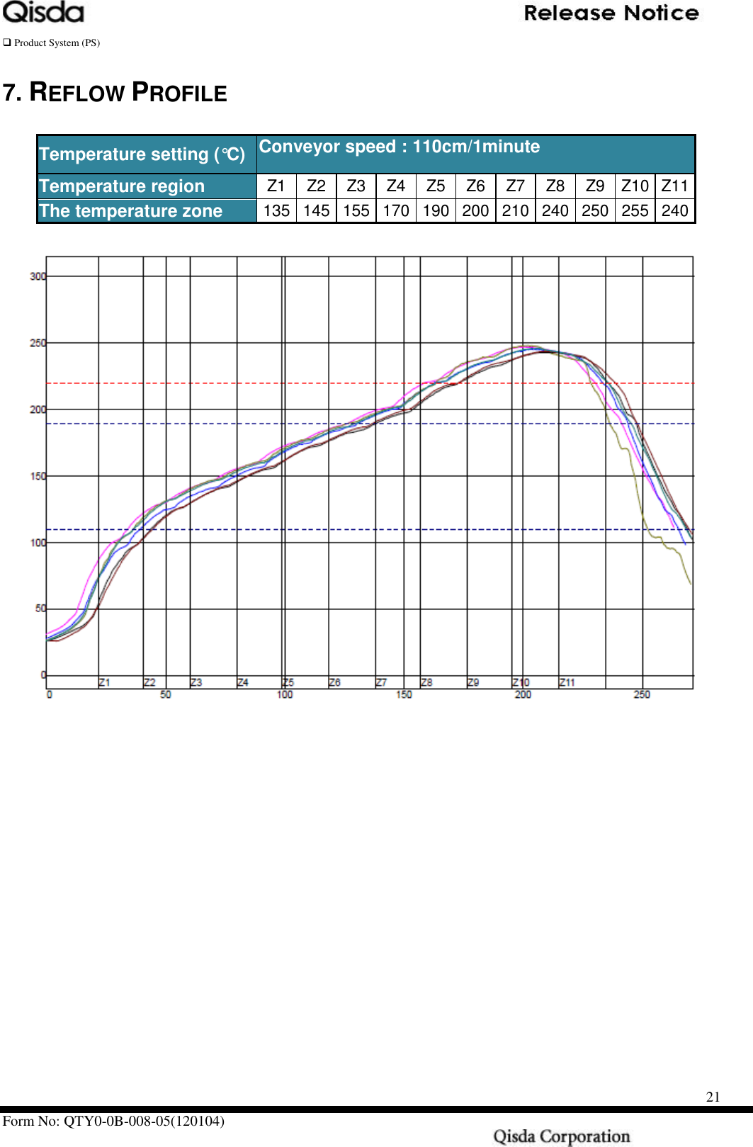
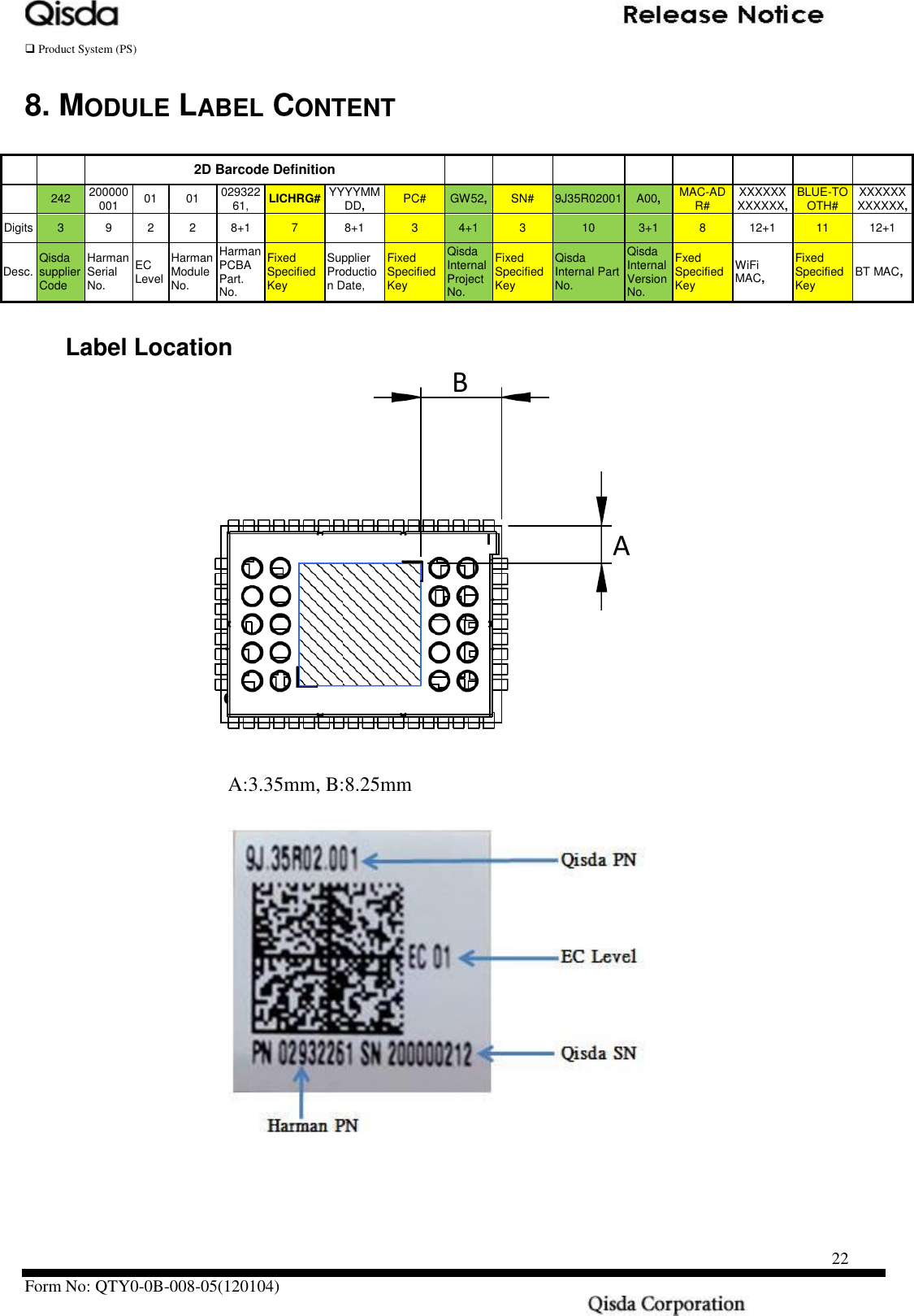
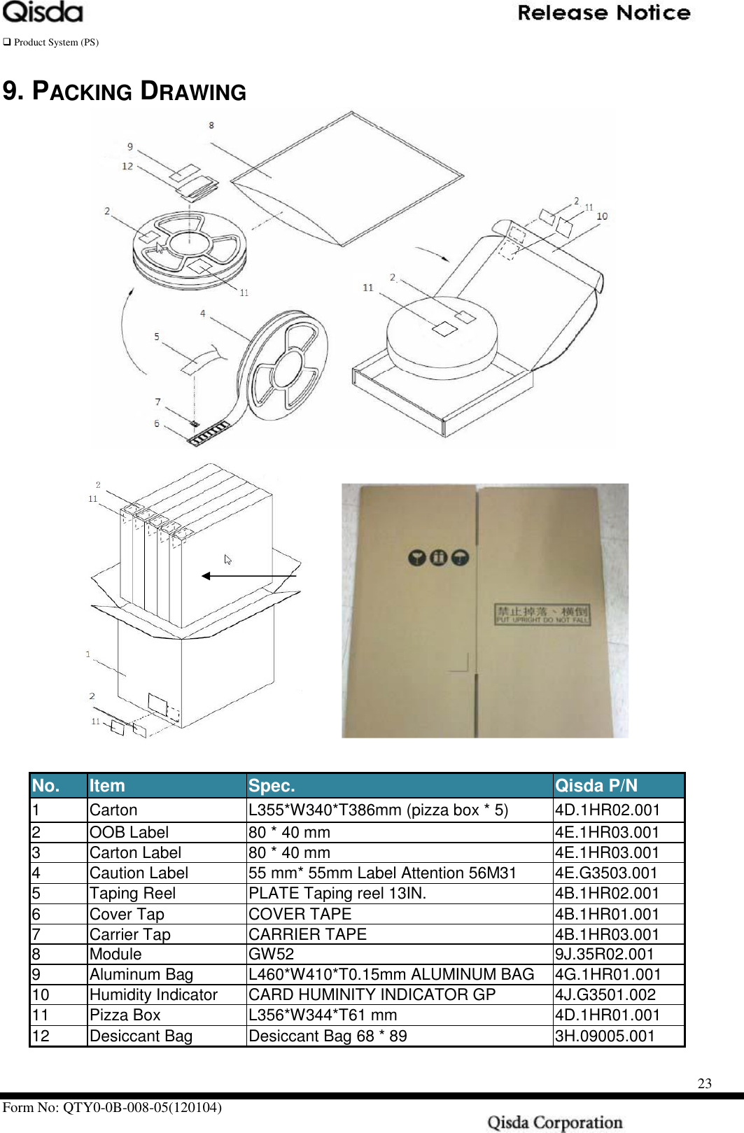
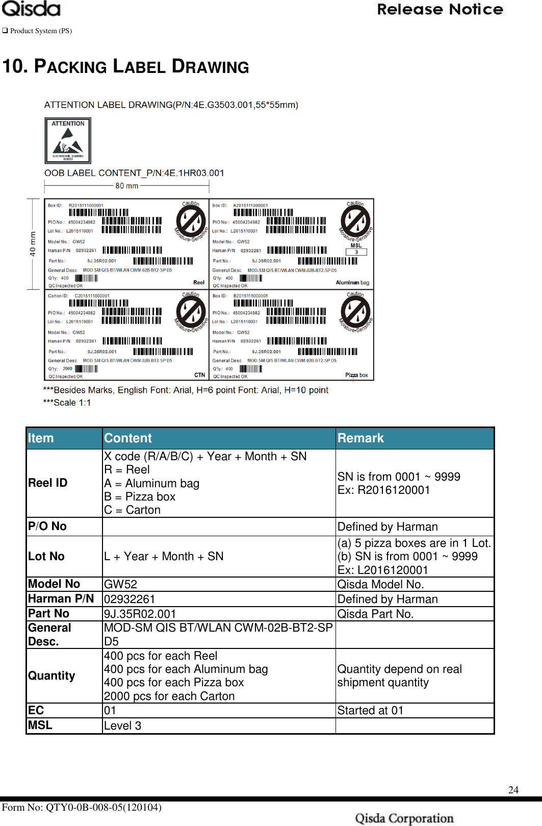
GW52 User Manual
User Manual
Navigation menu
Upload a User Manual
Namespaces
Wiki Guide
HTML
PDF
Info
Views
User Manual
Discussion / Help
Navigation