Qixiang Electron Science and Technology AT598V Mobile Radio User Manual AT598V
Qixiang Electron Science& Technology Co., Ltd Mobile Radio AT598V
Contents
User manual

-
L
E
N
N
A
H
U
-
VOL
PWR
FUNC
V/M
CALL
MHz
TX/DCS
SCAN
MINI
AT-598
Mobile Radiao
FCC ID:T4KAT598V
CAL
Thank you for choosing this vehicle transceiver,
always provides high quality products, And this transceiver is no
exception. As you learn how to use this transceiver, you will find that
is pursuing "user friendliness". For example, each time you
change the menu no. in Menu mode, you will see a text message on the
GLVSOD\WKDWOHWV\RXNQRZZKDW\RXDUHFRQ¿JXULQJ
Though friendly design for user, this transceiver is technically
complicated and some features may be new to you. Consider this
manual to be a personal tutorial from the designers, allow the manual to
guide you through the learning process now, then act as a reference in
the coming years.
Do not attempt to configure your transceiver while driving, it is
dangerous.
This transceiver is designed for a 13.8V DC power supply. Don't use
a 24V battery to power on the transceiver.
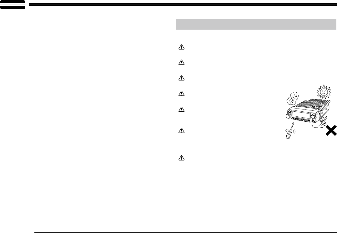
Do not place the transceiver in excessively dusty, humid or wet
areas, nor unstable surfaces.
Please keep it away from interferential
devices (such as TV, generator etc.).
Do not expose the transceiver to long
periods of direct sunlight nor place it close
to heating appliances.
If an abnormal odor or smoke is detected
coming from the transceiver, turn OFF the
power immediately. Contact an Anytone
service station or your dealer.
Do not transmit with high output power for extended periods; the
transceiver may overheat.
3OHDVHREVHUYHWKHIROORZLQJSUHFDXWLRQVWRSUHYHQW¿UHSHUVRQDOLQMXU\
or transceiver damage:
Precautions
-
L
E
N
N
A
H
U
-
VOL
PWR
FUNC
V/M
CALL
MHz
TX/DCS
H/L
SCAN
MINI
Mobile radio

CONTENTS
1HZDQG,QQRYDWLYH)HDWXUHV..............................................1
Supplied Accessories/Optional Accessories.....................2
Supplied Accessories....................................................................... 2
Optional Accessories .......................................................................2
,QLWLDO,QVWDOODWLRQ ..................................................................3
Mobile Installation ............................................................................3
DC Power Cable Connection ...........................................................4
Power Supply Voltage Display ......................................................... 6
Antenna Connection ........................................................................6
Accessories Connections................................................................. 7
*HWWLQJ$FTXDLQWHG ..............................................................8
Front panel....................................................................................... 8
Rear panel .......................................................................................9
Display .............................................................................................9
Microphone ......................................................................................10
Working Mode(Amateur Transceiver or Professional
Transceiver)
........................................................................11
Basic Operations .................................................................12
Switching the Power On/Off ............................................................12
$GMXVWLQJWKH9ROXPH ...................................................................... 12
Switch between VFO and Channel mode .......................................12
$GMXVWLQJ)UHTXHQF\&KDQQHOThrough Selector Knob.................... 12
Receiving .........................................................................................12
Transmitting .....................................................................................12
Transmitting Tone-Pulse ..................................................................13
Transmitting Optional Signaling ......................................................13
Channel Edit ....................................................................................13
Channel Delete ................................................................................13
Shortcut Operations.............................................................14
Squelch Off/Squelch Off Momentary................................................14
Squelch Level Setup ........................................................................14
Frequency/Channel Scan ................................................................14
Channel Scan ..................................................................................14
CTCSS/DCS Encode and Decode Setup ........................................14
CTCSS Scan....................................................................................15
DCS Scan ........................................................................................15
Compander (Decrease the background noise and enhance audio
clarity ..................................................................................................15
Offset Direction and Offset Frequency Setup ..................................16
Keypad Lockout ...............................................................................16
Current Voltage Enquiry...................................................................16
Auto-Dialer Setup.............................................................................16
Transmitting Edited DTMF Tones in the Auto-dialer Memory........... 17
General Setting.....................................................................18
Frequency Channel Step Setup....................................................... 18
DTMF, DTMF ANI, 2Tone or 5Tone Signaling .................................. 18
Sending 2-Tone Call.........................................................................19
Sending 5-Tone Call.........................................................................19
Sending DTMF call ..........................................................................19
Signaling Combination Setup...........................................................19

CONTENTS
Band-width Selection .......................................................................20
TX OFF Setup.................................................................................. 21
Busy Channel Lockout .....................................................................21
Editing Channel Name .....................................................................21
Reverse TX/RX ................................................................................ 21
Talk Around ......................................................................................22
Voice Compander ...........................................................................22
Scrambler Setup (Encryption).......................................................... 22
Radio's DTMF SELF ID ENQUIRY .................................................22
Radio's 5TONE SELF ID ENQUIRY ...............................................23
Voice Prompt.................................................................................... 23
TOT (Time-out timer) .......................................................................23
APO (Auto power off)....................................................................... 23
DTMF Transmitting Time.................................................................. 24
Squelch Level Setup ........................................................................24
Scan Dwell Time Setup....................................................................24
LCD Backlight ..................................................................................24
Pilot Frequency ................................................................................25
Display Mode Setup......................................................................... 25
PIN Setup ........................................................................................25
Address List ....................................................................................26
Factory Default.................................................................................26
Microphone Operation .........................................................27
Function Setup By Microphone Keypad........................................... 27
Squelch Level ..................................................................................27
Optional Signaling ...........................................................................27
Scan Skip ........................................................................................ 28
Frequency/Channel Scan ...............................................................28
Busy Channel Lockout .....................................................................28
Reverse TX/RX ................................................................................ 28
TOT (Time-out timer)........................................................................29
CTCSS/DCS Encode and Decode................................................... 29
Talk Around .....................................................................................29
Voice Prompt.................................................................................... 29
LCD Backlight .................................................................................30
Long-distance Anti-theft Alarm ..........................................31
Cable Clone ..........................................................................32
3URJUDPPLQJ6RIWZDUH,QVWDOOLQJDQG6WDUWLQJLQZLQGRZV
XP system) ............................................................................33
Maintenance..........................................................................34
Default Setting after Resetting(VHF) ...............................................34
Trouble Shooting..............................................................................34
6SHFL¿FDWLRQV .......................................................................35
Attached Chart......................................................................36
50 groups CTCSS Tone Frequency(Hz) ..........................................36
1024 groups DCS Code................................................................... 36

1
1
New and Innovative Features
598 Mobile Radio has nice housing, stoutness & stability, advanced and reliable functions, perfect & valuable. This amateur mobile radio especially
designs for drivers and it pursues company philosophy of innovation and practicality. More functions as follows:
'LVSOD\RQDODUJH/&'ZLWKDGMXVWDEOH EULJKWQHVVFRQYHQLHQWIRUQLJKWWLPHXVH
There are Amateur operation mode and Professional
operation mode for option.
Distribute buttons reasonably, convenient for operation. Adopt superior quality material, better technology and high quality radiator to ensure
stable and durable operation.
SURJUDPPDEOHPHPRUL]HGFKDQQHOVLGHQWL¿HGE\HGLWLQJQDPH
3URJUDPPLQJGLIIHUHQW&7&66'&67RQH7RQHLQSHUFKDQQHOUHMHFWLQJH[WUDFDOOLQJIURPRWKHUUDGLRV
Various scan functions including CTCSS/DCS Scan function.
Using
5Tone to send Message, Emergency alarm, Call all, ANI, Remotely kill, Remotely Waken, etc.
Automatic
calling,GHQWL¿FDWLRQIXQFWLRQE\DTMF--ANI or 5Tone--ANI .
Scramble function (Optional).
Compander function for decrease the background noise and
enhance audio clarity, it can set compander ON/OFF per channel.
Theft alarm provides extra safety.
2
2
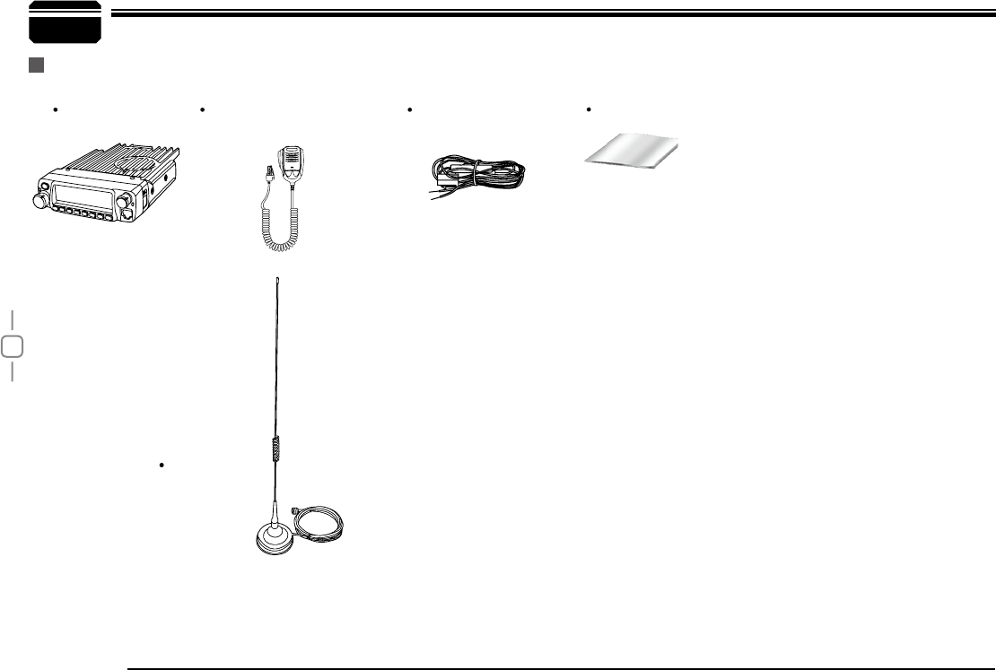
Supplied Accessories
After carefully unpacking the transceiver, identify the items listed in the table below. We suggest you keep the box and packaging.
Transceiver User Manual
Microphone (QHM-03)
(with DTMF keyboard)
DC Power Cable with
Fuse Holder(QPL-01)
-
L
E
N
N
A
H
U
-
VOL
PWR
FUNC
V/M
CALL
MHz
TX/DCS
H/L
SCAN
MINI
Supplied Accessories
Car Antenna
(QCA-01)
Car Antenna
(QCA-01)
Antenna Gain:0dBi
3
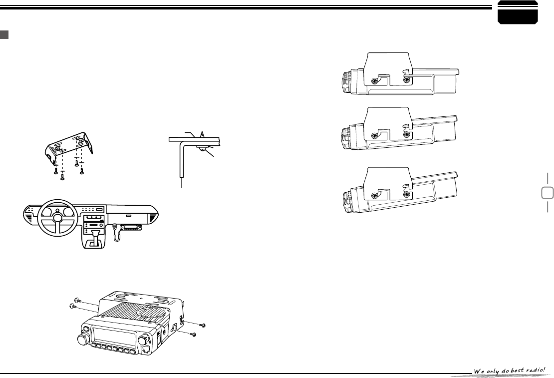
To install the transceiver, select a safe, convenient location inside your
vehicle that minimizes danger to your passengers and yourself while the
vehicle is in motion. Consider installing the unit at an appropriate position
so that knees or legs will not strike it during sudden braking of your
vehicle. Try to pick a well ventilated location that is shielded from direct
sunlight.
Install the mounting bracket in the vehicle using the supplied self-
1.
WDSSLQJVFUHZVSFVDQGÀDWZDVKHUVSFV
Position the transceiver, then insert and tighten the supplied
2.
hexagon SEMS screws.
Double check that all screws are tightened to prevent vehicle
vibration from loosening the bracket or transceiver.
3
Car body
Washer (M5)
Tapping screw
(M5x20mm)
Mounting bracket
Initial Installation
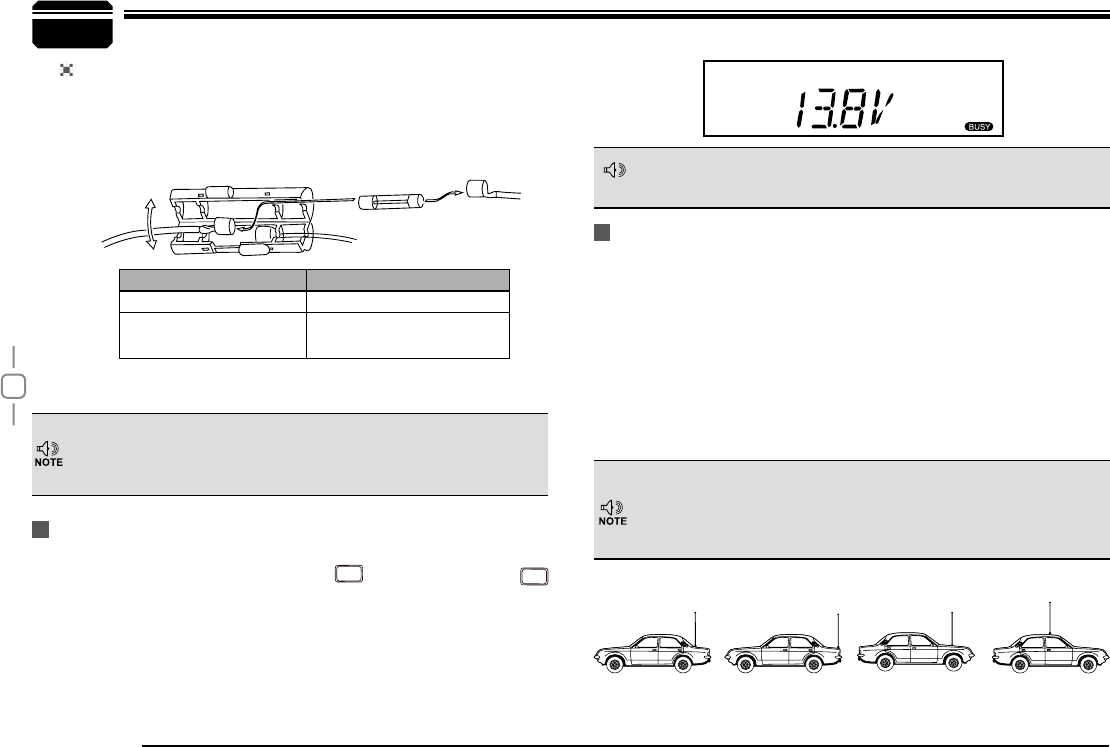
Mobile installation Determine the appropriate angle of the transceiver, using the 3 screw
hole positions on the side of the mounting bracket.
-
L
E
N
N
A
H
U
-
VOL
PWR
FUNC
V/M
CALL
MHz
TX/DCS
SCAN
MINI
CAL
4
Connect the DC power cable to the transceiver's power supply
6.
connector.
Press
WKHFRQQHFWRUV¿UPO\WRJHWKHUXQWLOWKHORFNLQJWDEFOLFNV
If the ignition-key on/off feature is desired(optional feature), use the
3
Red
Black
([W3RZHUMDFN
DC power cable
Initial Installation
DC Power Cable Connection
Mobile Operation
In many cars,the cigar-lighter plug is always powered. If this is the case, you
cannot use it for the ignition key on/off function.
The vehicle battery must have a nominal rating of 12V. Never
connect the transceiver to a 24V battery. Be sure to use a 12V
vehicle battery that has sufficient current capacity. If the current
to the transceiver is insufficient, the display may darken during
transmission, or transmitting output power may drop excessively.
When the ignition key is turned to ACC or ON(Start) position with
7.
the radio turned off, the power switch illuminates. The illumination
will be turned off when the ignition key is turned to the off position.
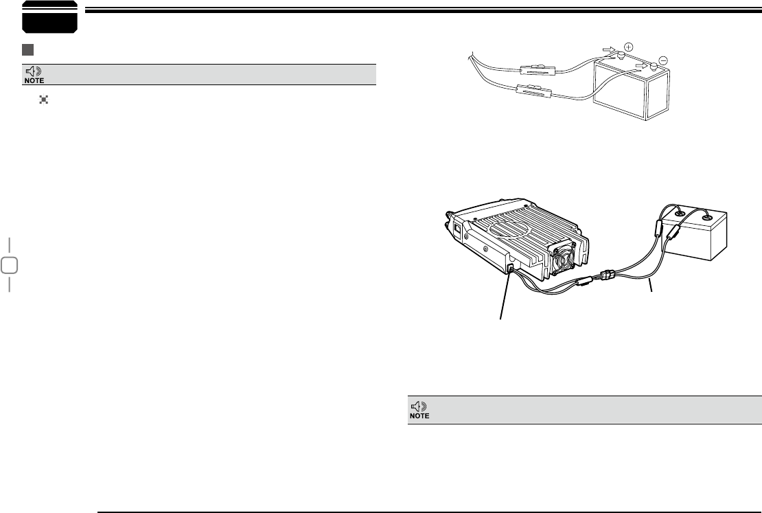
Route the DC power cable supplied with the transceiver directly
1.
to the vehicle's battery terminals using the shortest path from the
transceiver.
We recommend you do not use the cigarette lighter socket as
some
cigarette lighter sockets introduce an unacceptable voltage drop.
The entire length of the cable must be dressed so it is isolated from
heat, moisture, and the engine secondary (high voltage) ignition
system/ cables.
After installing cable, in order to avoid the risk of damp, please
2.
use heat-resistant tap to tie together with fuse box. Don't forget to
reinforce whole cable.
In order to avoid the risk of short circuit, please cut down
3.
connection with negative (-) of battery, then connect with radio.
Confirm the correct polarity of the connections, then attach the
4.
power cable to the battery terminals; red connects to the positive (+)
terminal and black connects to the negative (-) terminal.
Use the full length of the cable without cutting off excess even if
the
cable is longer than required. In particular, never remove the fuse
holders from the cable.
Reconnect any wiring removed from the negative terminal.
5.
optional QCC-01(For Cigar-Plug connection) cable. Connect one of
the cables between the ACC terminal or a Cigar-Plug that operates
with the vehicle ignition or ACC switch on the vehicle and EXT
32:(5MDFNRQWKHUHDUVLGHRIWKHXQLW
Locate the power input connector as close to the transceiver as possible.
5
3
Red
Black
Regulated power supply (QRP-01)
DC power cable with fuse holder (QPL-01)
Regulated
power supply
(QRP-01)
([W3RZHUMDFN
ACC terminal
Cigar-Plug connection
Initial Installation
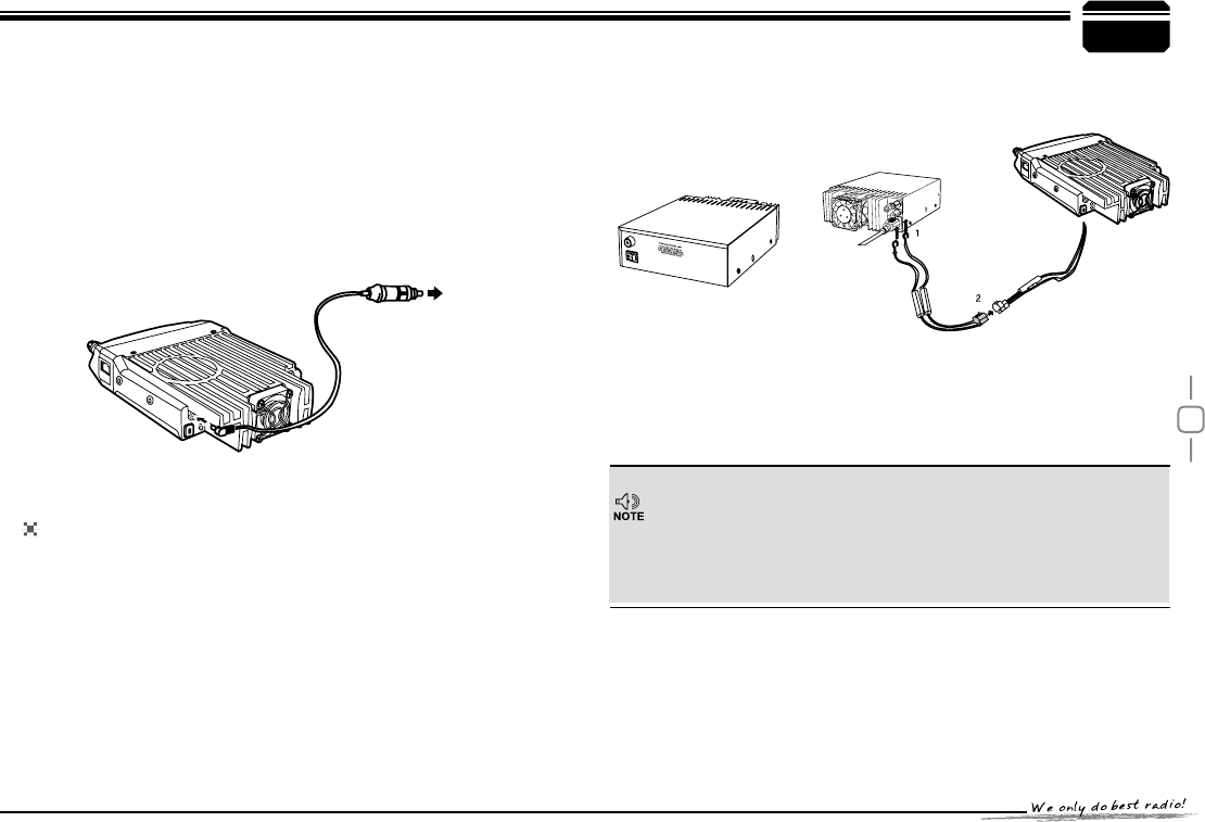
Before connecting the DC power to the transceiver, be sure to switch
the transceiver and the DC power supply OFF.
Do not plug the DC power supply into an AC outlet until you make all
connections.
In order to use this transceiver for fixed station operation, you will
need a separate 13.8V DC power supply (not included), power
supply( QRP-01) as optional accessories. Please contact local dealer
to require.
The recommended current capacity of your power supply is 12A.
Connect the DC power cable to the regulated DC power supply
1.
and ensure that the polarities are correct. (Red: positive, Black:
negative).
Do not directly connect the transceiver to an AC outlet.
Use the supplied DC power cable to connect the transceiver to a
regulated power supply.
Do not substitute a cable with smaller gauge wires.
To turn on the unit, press the power switch manually while it is
illuminated. (While ignition key is at ACC or ON position)
When the ignition key is turned to ACC or ON position with the
8.
radio's power switch on, the unit turns on automatically and the
power switch will be lit. Turn the ignition key to OFF position or
manually turn the power switch off to shut down the radio.
Using extra cable, power consumption:5MAH.
9.
Without this function, user can turn on/off radio by Power knob.
10.
Connect the transceiver's DC power connector to the connector
2. on
the DC power cable.
3UHVVWKHFRQQHFWRUV¿UPO\WRJHWKHUXQWLOWKHORFNLQJWDEFOLFNV
.
Fixed Station Operation
The EUT can be used on vehicle.
6
3Initial Installation
REPLACING FUSES
If the fuse blows, determine the cause, then correct the problem.
After the problem is resolved, replace the fuse. If newly installed fuses
continue to blow, disconnect the power cable and contact your autho-
rized dealer or an authorized servi-
cecenter for assistance.
Only use fuses of the specified type and rating, otherwise the
transceiver could be damaged.
After connecting the transceiver to the power supply, the supply voltage
can be displayed on LCD by pressing the
FUNC
key together with the
SCAN
key.
The display immediately changes as the voltage supply changes, It also
displays voltage during transmission.
The transceiver will return to its normal operation when the power is
switched ON or repeat above operation.
%HIRUHRSHUDWLQJLQVWDOODQHI¿FLHQWZHOOWXQHGDQWHQQD7KHVXFFHVVRI
your installation will depend largely on the type of antenna and its correct
installation. The transceiver can give excellent results if the antenna
system and its installation are given careful attention.
8VHDȍLPSHGDQFHDQWHQQDDQGORZORVVFRD[LDOIHHGOLQHWKDW
KDVDFKDUDFWHULVWLFLPSHGDQFHRIȍWR PDWFKWKHWUDQVFHLYHULQSXW
impedance. Coupling the antenna to the transceiver via feed-lines having
DQLPSHGDQFHRWKHUWKDQȍUHGXFHVWKHHIILFLHQF\RIWKHDQWHQQD
system and can cause interference to nearby broadcast television
receivers, radio receivers, and other electronic equipment.
Fuse Location Fuse Current Rating
Transceiver 15A
Supplied Accessory DC
power cable 20A
If you use the transceiver for a long period when the vehicle battery is
not fully charged, or when the engine is OFF, the battery may become
GLVFKDUJHGDQGZLOOQRWKDYHVXI¿FLHQWUHVHUYHVWRVWDUWWKHYHKLFOH$YRLG
using the transceiver in these conditions.
The range of displayed voltage is only from 7V to16V DC, because the
displayed value is estimated, please use a voltmeter when a more precise
reading is desired.
Power supply voltage Display
Antenna Connection
,PSRUWDQW
Transmitting without first connecting an antenna or other matched
load may damage the transceiver. Always connect the antenna to the
transceiver before transmitting.
$OO¿[HGVWDWLRQVVKRXOGEHHTXLSSHGZLWKDOLJKWQLQJDUUHVWHUWRUHGXFH
WKHULVNRI¿UHHOHFWULFVKRFNDQGWUDQVFHLYHUGDPDJH
The possible locations of antenna on a car are shown as following:
mobile radio mobile radio
7
3
Ground
Microphone
connector
Error
IUUQXXXRYE[DO
Initial Installation
External Speaker
Microphone
PC Connecting
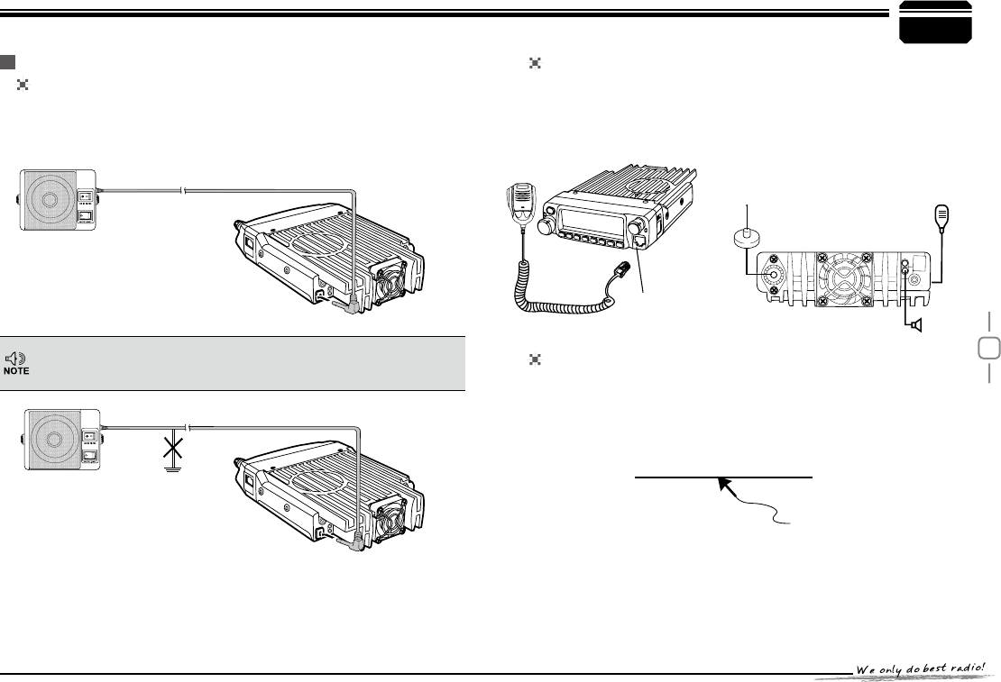
If you plan to use an external speaker, choose a speaker with an
LPSHGDQFHRIȍ7KHH[WHUQDOVSHDNHUMDFNDFFHSWVDPP
mono (2-conductor) plug.
For voice communications, connect a microphone equipped with an
8-pin modular plug into the modular socket on the front of the main
XQLW3UHVV¿UPO\RQWKHSOXJXQWLO WKHORFNLQJWDEFOLFNV$WWDFK WKH
supplied microphone hanger in an appropriate location using the
screws included in the screw set.
7RXWLOL]HWKHRSWLRQDO436VRIWZDUH\RXPXVW¿UVWFRQQHFWWKH
transceiver to your PC then using an optional programming cable
PC50 (via Data socket ).
Please use QPS598 software for programming.
External speaker adopt double port BTL, please care about the connecting
way. The speaker can not connect with the ground, otherwise the speaker
will be fault. The wrong connecting way as the following picture.
Accessories Connections
41
41
External speaker[SP-02]
Microphone
[QHM-04]
Antenna[QCA-02]
-
L
E
N
N
A
H
U
-
VOL
PWR
FUNC
V/M
CALL
MHz
TX/DCS
H/L
SCAN
MINI
8
4
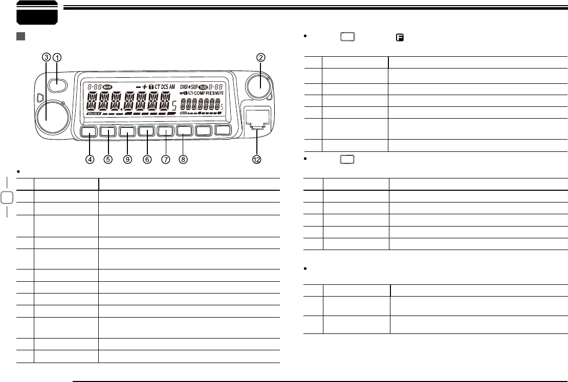
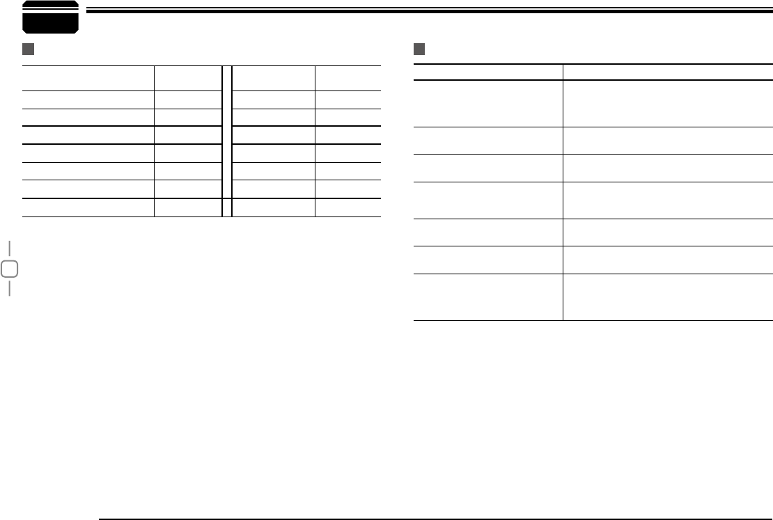
NO. KEY )81&7,21
Pow(Power) Power on/Off
VOL $GMXVW9ROXPH.H\
Main Dial Change frequency, memory channel and scan
direction etc.
FUN/SET Function Key
V/M/MW Switches between VFO mode and Channel
mode
MHz/SHIFT Step Size Key ( step:1MHz)
TS/DCS/LOCK Sets CTCSS and DCS value
Call key
SQL/D Squelch off
Data Terminal Data reading/writing, cloning and theft alarm
functions
TX lights during Transmitting
Mic.connector Microphone connection port
NO. KEY )81&7,21
FUN/SET &RQ¿UPVWKHVHOHFWLYHIXQFWLRQVDQGH[LW
V/M/MW Stores data into channels
MHz/SHIFT Sets offset direction and offset frequency
TS/DCS/LOCK Sets Keypad lock function
SQL/D Compander mode on/off
NO. KEY )81&7,21
Pow(Power)
Reset to factory default settings
V/M/MW Erase the memory
TS/DCS/LOCK Auto dialer
Enters clone data function mode
SQL/D Enters power supply voltage indication mode
NO. KEY )81&7,21
FUN/SET Press and hold for 2s to enter the Setting
mode
SQL/D Monitor mode
Getting Acquainted
Front panel Press
FUNC
key until LFRQDSSHDUVWKHQSUHVVWKHIROORZLQJ
key.
Press
FUNC
NH\DQGIROORZLQJNH\WRJHWKHU WRDFWLYDWH
IROORZLQJIXQFWLRQ
)XQFWLRQVWKDWUHTXLUHFRQWLQXRXVSUHVVLQJIROORZLQJNH\
to be activated
%DVLF)XQFWLRQV
PWR
FUNC
V/M
CALL
MHz
TX/DCS
SCAN
MINI
-
L
E
N
N
A
H
U
-
VOL
power
CAL
CAL
CAL
CAL
9
4
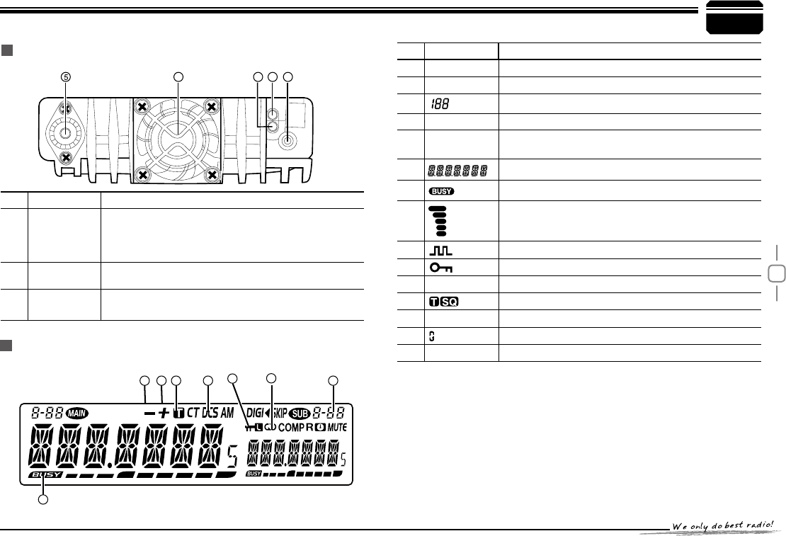
NO. KEY )81&7,21
Ext. Power
Jack
Terminal for connecting optional cable QCC01 for
use with ignition key On/Off function.
The radio will auto power on when car is driving.
The radio will auto power off when car stops.
Ext.Speaker
Terminal Terminal for optional external speaker SP01
Antenna
Connector &RQQHFWLRQIRUȍFRD[LDOFDEOHDQGDQWHQQD
NO. KEY )81&7,21
SQL Squelch level.
MIn channel mode.
Indicates the channel number in channel mode.
Decimal point
Channel skip.
Decimal point Indicates the decimal point of frequency and the
scanning function.
Indicates the frequency or memory name.
Signal is being received or monitor.
Signal strength of receiving and transmitting.
Compander.
Keypad lock .
DCS Set DCS function.
Set CTCSS function.
+_Offset frequency direction.
Scramble.
A Auto power off.
Getting Acquainted
DISPLAY
Rear panel
4132
13 13 10
11
12 14
7
3
10
4
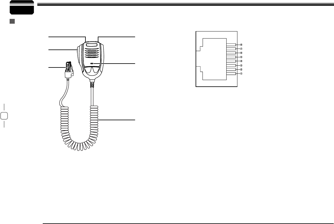
,FZ1BE4FSJBM%BUB
7
%08/
61
.*$(/%
.*$
155
(/%
microphone MIC Connector Diagram(in the front view of connector)
Getting Acquainted
$IBOOFM%PXO $IBOOFM61
.JDSPQIPOF
DBCMF
.JD
155
$POOFDUPS
11
5
According to practical application, you can set the radio works as
Amateur Transceiver mode or Professional Transceiver mode. There
are also 2 levels operation menu to set functions as you need. It is easy
and convenient (From No.1 to No.15 are channel function setup, From
No.15 to No.29 are general setting setup).
:RUNLQJ0RGH
1.
%\SURJUDPPLQJVRIWZDUHA. In PC software's "General Setting"
menu, choose "Display Mode" to select Amateur Transceiver
mode or Professional Transceiver mode.
By manual setupB. : Please refer to "Display Mode" in Page 25.
$PDWHXU7UDQVFHLYHU0RGH
2. Except setting as "CH" mode, others
considered as Amateur transceiver mode. Under this mode, press
V/M
key to switch between Channel mode and VFO mode .
3URIHVVLRQDO7UDQVFHLYHU0RGH
3. When
set display mode as "CH", it enters
into Professional Transceiver mode.At
this mode, except scan, other shortcut
operation can't operate. And from No.1-
17 menu in function setting will be
auto-hidden, they should be set by PC
software.If there is corresponding name
for current channel, the LCD will display
current channel name Otherwise, it
shows current channel number. (As pic 4) (As pic 5)
Under every mode, from No.18-29 menu in
4. general setting can be
changed and saved.
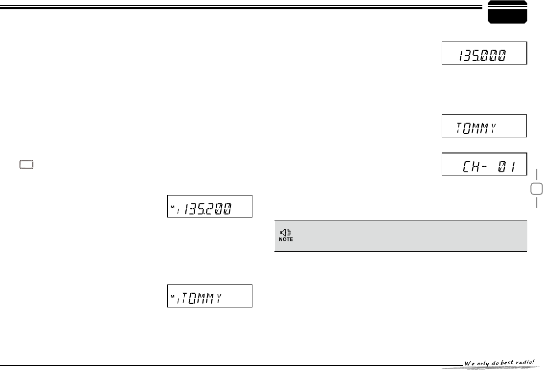
9)20RGH)UHTXHQF\PRGHC. :
This mode shows only frequency on
the display. Shortcut operation and
Channel setting will be changed &
stored as the latest value permanently.
Once the radio is turned off or
changed to new VFO frequency, the latest setting is remained
until next change.(As pic 3)
If transceiver programmed as professional transceiver mode and
locked, you can't return to amateur transceiver mode by manual
operation from general setting.
(Pic 1)
(Pic 2)
(Pic 4)
(Pic 5)
)UHTXHQF\&KDQQHOPRGHA. : When set display as "FR", it
enters into Frequency+Channel
mode, new setting of channel
operation and shortcut operation can
be temporarily used by user. Once
the radio is turned off or switched
to another channel, the temporary
setting will be erased and back to initial settings.(As pic 1)
&KDQQHO1DPH7DJ0RGHB. : When set display as "NM", it enters
into Channel+Name Tag mode. At this mode, it will display
corresponding channel name when
the current channel is edited with
name. Otherwise, it will display
frequency+channel. Its operations
are the same as frequency + channel
mode.(As pic 2)
(Pic 3)
WORKING MODE (AMATEUR TRANSCEIVER OR PROFESSIONAL TRANSCEIVER)
12
In standby, press
V/M
key or Microphone's
MINI
key until appear , this indicates current
channel in channel mode. Repeat above
6
PWR KEY
Dial
Frequency
decrease
Frequency
increase
Min
Volume
Max
Volume
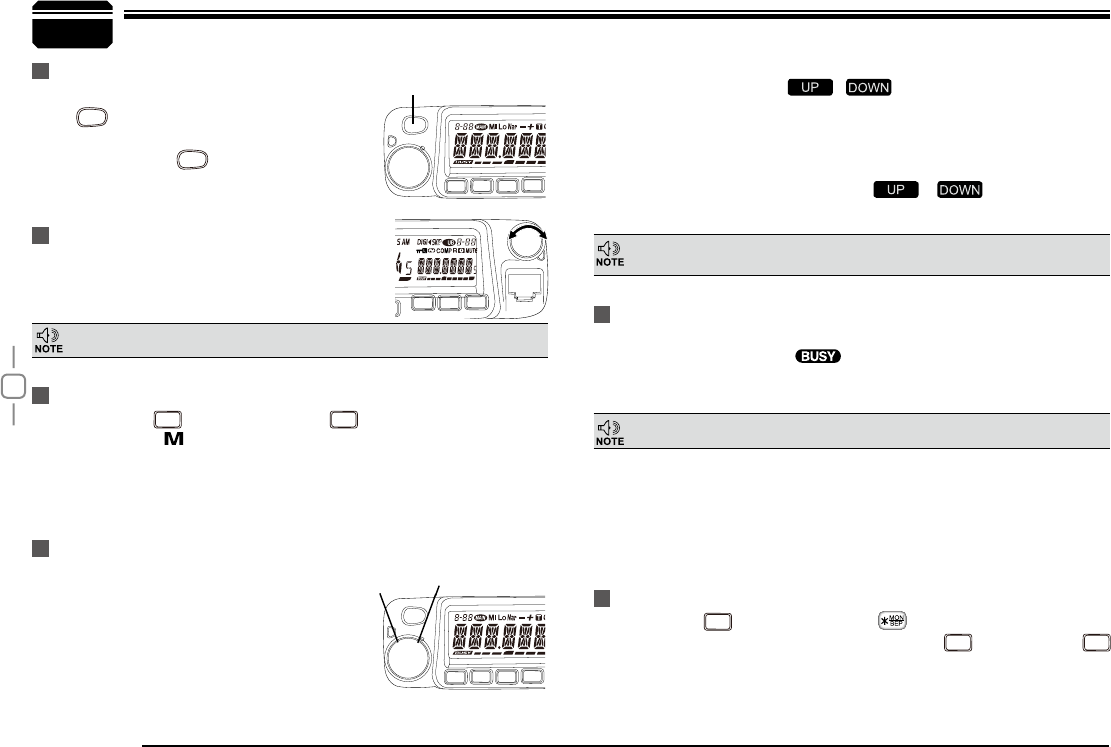
Basic Operations
Switching The Power On/Off
Adjusting The Volume
Switch between VFO and Channel mode
Adjusting Frequency/Channel THROUGH SELECTOR KNOB
Receiving
According to the option selected during installation
Press
PWR
the switch or turn the ignition key to
ACC (speed up) or ON (startup) position to power
on radio. Press the
PWR
key for 1s or turn the
ignition key to OFF position to turn off.
When the channel you are operating is
called, the screen shows and field
intensity, in this way, you can hear the calling
from transmitting party.
Under frequency (VFO) mode, you can
1.
change the current frequency to the
desired one through selector knob; Turn
clockwise to increase frequency; turn
counterclockwise to decrease. Every
gear will increase or decrease one
step. Press key, the decimal point of
Turn the VOL knob clockwise to increase the
audio level, counterclockwise to decrease.
'XULQJFRPPXQLFDWLRQYROXPHFDQEHDGMXVWHGPRUHDFFXUDWH
five step size
available for this radio.
If the transceiver has set at higher squelch level, it may fail to hear the calling.
operation to switch between Frequency mode
(VFO) and Channel mode.
frequency in screen will be auto-hidden. In this status, turn selector
knob or Microphone [ / ] key will increase or decrease
frequency quickly by 1MHz step.
Under channel mode, you can change the current channel to the
2.
desired one through selector knob, clockwise turn to the forward
channel, anticlockwise turn to the backward channel. In relative
working mode, Microphone's [ / ] key has same
IXQFWLRQIRUDGMXVWLQJIUHTXHQF\DQGFKDQQHO
Transmitting
Press and hold
MINI
key or press MIC's key to monitor for a while to
FRQ¿UPWKHFKDQQHOGHVLUHGLVQRWEXV\ Release
SCAN
or press Mic's
MINI
key to return standby status, then press and hold [PTT] key to speak into
microphone.
When the channel you are operating is called, the screen shows BUSY
and field intensity, you can't hear the calling from transmitting party,
it means current channel receives a matching carrier but unmatching
signaling(Refer to CTCSS/DCS encode and decode or Optional Signaling
setup).
DCS
SCAN
MINI
VOL
PWR
FUNC
V/M
CALL
MHz
-
L
E
N
N
A
H
U
-
PWR
FUNC
V/M
CALL
MHz
-
L
E
N
N
A
H
U
-
5k, 6.25k, 8.33K,10k, 12.5k, total
CAL
13
Basic Operations
Transmitting Tone-Pulse
Transmitting OPTIONAL SIGNALING
Press and hold [PTT] key, then press Microphone [ ] key to
transmit current selected tone-pulse signal.
Press and hold [PTT] key, then press Microphone key or press
CALL
key in front panel or press Mic's
MINI
key to transmit pre-stored and
selected DTMF/2Tone/5Tone optional signaling.
Channel Edit
Channel Delete
Under frequency mode (VFO), turn
1.
selector knob to select the desired
frequency or input frequency by MIC's
numeric keys.
Press
2.
TX/DCS
key to enter CTCSS/DCS
signaling setup, turn selector knob to
select the desired signaling.
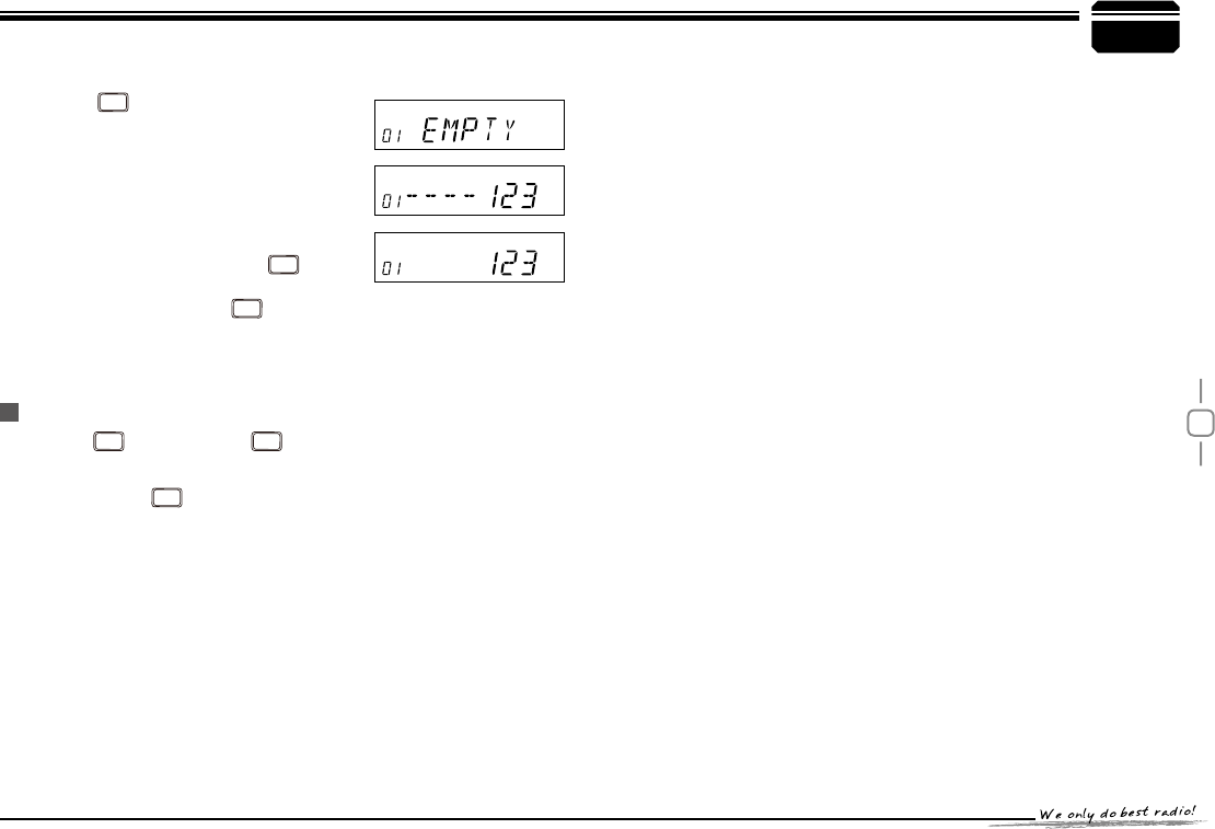
Press
3.
FUNC
key, LCD appears ,
icon and current channel number,
LFRQÀDVKLQJPHDQVFXUUHQWFKDQQHOLV
Under channel mode, turn selector knob to select channel which
1.
you want to delete.
Press
2.
FUNC
key and
V/M
key together, current channel will be
deleted and emitted a prompt voice. LFRQÀDVKLQJPHDQVFXUUHQW
channel is deleted.
empty.
Turn selector knob to select the desired channel number to store.
4.
Press
5.
V/M
key, , icon and channel number disappears and
emit a prompt voice, thus the channel storage succeed.
6
Please hold the microphone approximately 2.5-5.0cm from your lips
,
and then speak into the microphone in your normal speaking voice to
get best timbre.
Press and hold [PTT] key, LED lights RED and power intensity showed in
screen indicates it is transmitting, release to receive.
14
7Shortcut Operations
Squelch level Setup
Frequency/Channel Scan
Channel Scan
CTCSS/DCS Encode and Decode setup
Setting the radio to a tight squelch level, you can avoid unwanted signals
or noise, but you may not receive a weak signal. Therefore, it will be
better for you to select the normal squelch level.
In frequency (VFO) mode, this function is designed to monitor signal
of every communicative frequency point of transceiver "step size" you
have set.
In channel mode, this function is designed to monitor signal in every
channel.
In channel mode, Press
1.
V/M
key for 1s to enter into channel scan.
Repeatedly press
TX/DCS
key to check whether set CTCSS/DCS encode
and decode in current channel or not.
While standby, press
1.
SCAN
key and turn
selector knob until LCD appears
and current squelch level.
Turn selector knob or press MIC [
2.
/ ] key to set desired squelch level.
Press any key except
3.
PWR
and
FUNC
key
to exit.
Frequency Scan
In VFO mode, press
1.
V/M
for 1s to enter
into frequency scan.
Turn selector knob or press Microphone
2.
[ / ] key to change scan direction.
Press any key except
3.
PWR
and
FUNC
key to exit.
Turn selector knob or press Microphone
2.
[ / ] key to change scan
direction.
Press any key except
3.
PWR
and
FUNC
key
to exit.
squelch off/squelch off momeNTARY
SCAN
key programmed as Squelch Off or Squelch Off Momentary to
monitor the weak signal.
Squelch Off: Press
1.
SCAN
key to disable squelch, press
SCAN
key again
to resume squelch.
Squelch Off Momentary: Press and hold
2.
SCAN
key to disable
squelch, release
SCAN
key to resume squelch.
The above functions should be set in programme software.
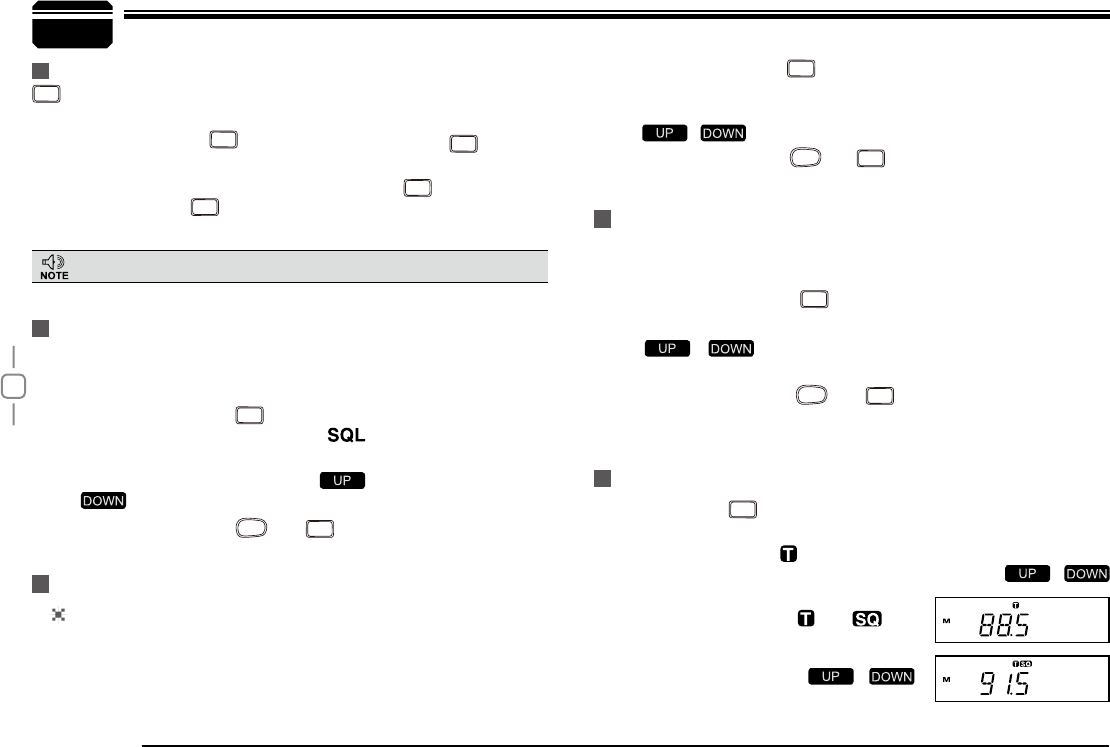
When LCD appears
1. icon, it means current channel with CTCSS
encode, turn selector knob or press Microphone's [ /
] key to select desired CTCSS encode.
When LCD appears
2. and icon,
it means current channel with CTCSS
encode and decode, turn selector knob
or press Microphone's [ / ]
to select desired CTCSS code.
15
7
Shortcut Operations
CTCSS SCAN
Repeatedly press
TX/DCS
key until LCD displays
and icons, then hold
TX/DCS
key for 1S
WRHQWHULQWR&7&66VFDQQLQJ2QFH¿QGLQJ
a matching CTCSS signaling, it will stop for
15s then scan again.
Under channel mode, this operation can be temporarily used by user. Once
the radio is turned off or switched to another channel, the temporary setting
will be erased.
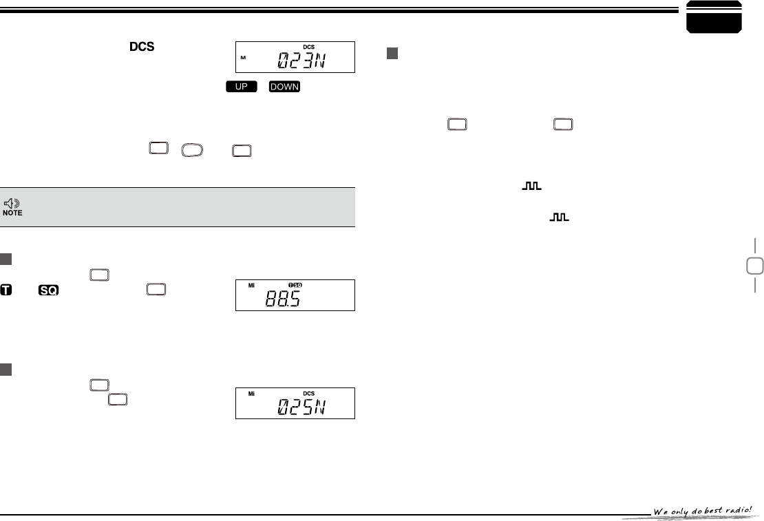
When LCD appears
3. icon, it means
current channe can be set with DCS
encode and decode together, turn
selector knob or press Microphone's [ / ] to select
desired DCS encode and decode.
CTCSS:62.5-254.1, Total 51groups; DCS:000N-777I total 1024
4.
groups. N is positive code, , is inverse code.
Press any key except
5.
FUNC
,
PWR
and
TX/DCS
keys to return into
standby status.
Repeatedly press
TX/DCS
key until LCD displays
DCS icons, then hold
TX/DCS
key for 1S to enter
LQWR'&6VFDQQLQJ2QFH¿QGLQJDPDWFKLQJ
DCS signaling, it will stop for 15s then scan
again.
Compander function will decrease the background noise and enhance
audio clarity, especially in long range communication.
Press
1.
FUNC
key, then press
SCAN
key to
turn on compander function, repeat
above operation again to turn off
compander function.
Compander (Decrease the background noise and ENHANCE
AUDIO CLARITY)
When LCD appears
2. icon, enable
compander in current channel.
When LCD doesn't display
3. icon, disable compander in current
channel.
DCS SCAN
16
Press
1.
FUNC
key until LCD displays icon,
then press
TX/DCS
key until, LCD displays
icon, it indicates keypad lockout
function is valid.
Repeat above operation,
2. icon disappears, it indicates keypad
lockout function is invalid.
This will automatically transmit pre-programmed and stored DTMF
tones. And they are often used to remote control electronic devices or
AUTOPATCH phone systems available on some repeater.
Press and hold
1.
FUNC
key, then press
TX/DCS
key to enter the auto-dialer
enquiry mode, LCD displays current default data and current group
displayed on left. If no data in current group, it shows "EMPTY".
Turn selector knob to choose group you desired. Total:16 group,
2.
Press and hold
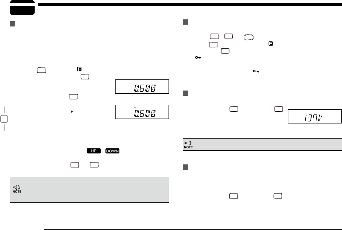
1.
FUNC
key, then press
SCAN
key, LCD displays current battery voltage.
Repeat above operation to return into
2.
VFO or Channel mode.
When LCD displays " " icon, it indicates negative offset, which
4.
means transmitting frequency lower than receiving frequency.
Turn selector knob or Mic's [
5. / ] key to change offset
frequency, offset frequency changed as per stepping.
Press any key except
6.
FUNC
and
MHz
key to exit into standby.
Press
1.
FUNC
key until the icon displays
on the LCD, then press
MHz
key, LCD
displays offset direction and offset
frequency.
Repeatedly press
2.
MHz
key to select
positive offset and negative offset.
When LCD displays " " icon, it indicates
3.
positive offset, which means transmitting
frequency higher than receiving
frequency.
7
Avoiding unintentional operation, this function will lock main keys, all
keys except
SCAN
/
FUNC
and
PWR
key are invalid.
KEYPAD LOCKOUT
Current Voltage ENQUIRY
Auto-Dialer Setup
Shortcut Operations
This function will display Current Battery Voltage.
Under channel mode, this operation can be temporarily used by
user.
Once the radio is turned off or switched to another channel, the
temporary setting will be erased.
In voltage display mode, all functions and channel or frequency
selection are invalid.
Repeater receives a signal(UP-LINK) on one frequency and re-transmits
on another frequency(DOWN-LINK). The difference between these two
frequencies is called the offset frequency. If the UP-LINK frequency
higher than DOWN-LINK frequency, the direction is positive, If it is lower,
the shift direction is negative.
Offset Direction and offset frequency setup
17
7
Shortcut Operations
Press
1.
FUNC
key, then press
TX/DCS
key to enter into auto-dialer enquiry
Turn selector knob to select desired transmitting group
2.
Press PTT or
3.
SCAN
key to transmit current selected DTMF tones.
Transmitting Edited DTMF tones in the Auto-dialer memory
01-16.
Press
3.
SCAN
key to enter into editing of
current group, press MIC's numeric
keys to set your desired data.
The display scrolls when the 7th digit
4.
is entered. The numbers 0-9, --, A-D, *
and # can be stored up to a total of 23
digits.
After editing, press PTT or
5.
SCAN
key to
send current group and store edited
DTMF signaling. Press
SCAN
to exit and
store.
18 Press and hold
1.
FUNC
key for over 2s to enter general setting menu.
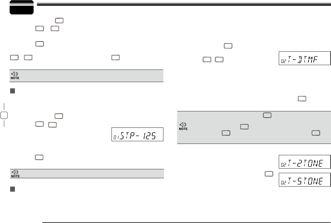
Press
2.
CALL
/
SCAN
key to choose No.01 menu, LCD displays "STP--
125".
Turn selector knob to select the desired
3.
frequency channel step. Channel step: 5K, 6.25K, 8.33K, 10K,
Press
4.
TX/DCS
NH\WRFRQ¿UPDQGH[LW
Press and hold
1.
FUNC
key for over 2s to enter general setting menu.
Press
2.
CALL
or
SCAN
to select the desired function option.
Turn selector knob to select the desired setup.
3.
Press
4.
TX/DCS
WRFRQ¿UPDQGH[LW
Meanwhile, if you want to edit channel name or start up menu, press
V/M
or
TX/DCS
to move forward or backward, Press
MHz
to store and exit.
Only in frequency (VFO) mode, this function is valid. Turn selector
knob to select frequency or frequency scanning which is restricted by
frequency step size.
8General Setting
Frequency Channel Step Setup
This function is auto-hidden in channel mode.
DTMF, DTMF ANI, 2Tone or 5Tone Signaling
DTMF/5Tone/2Tone signalling function as similarily as CTCSS/DCS.
Without receiving correspondent tone signalling, the speaker will remain
mute. DTMF and 5Tone signalling can be applied for other advanced
features such as ANI, PTT ID, group call, remotely stun, remotely kill,
waken,...etc.. The signalling edition must be done through programming
software. Please refer to the HELP option in the programming software
to know how to operate these features.
Press and hold
1.
FUNC
key for over 2s to
enter into general setting menu.
Press
2.
CALL
/
SCAN
to choose No.2 menu,
LCD displays "72))".
Turn selector knob to
3. select the desired setup.
"
'70)": The channel will be mute by a DTMF signal. The
speaker won’t be open until receiving a correspondent DTMF
signal. Hold "PTT" then press [UP] or press
CALL
directly to
transmit the pre-stored DTMF signaling.
In Profession transceiver mode, the functions from No.1 to No.17
will be auto-hidden.
In DTMF signaling mode,press
CALL
for 2s until LCD displays
"AN---", turn selector knob to select desired digit (the other party
ID).In this mode, press
TX/DCS
WRFRQ¿UPH[LVWGLJLWDQGPRYHFXUVRU
to next, press
V/M
to forward cursor.After editing, press
CALL
key
to operate ANI call.
"
2TONE": The channel will be mute
by a 2-Tone signal. The speaker
won’t be open until receiving a
correspondent 2-Tone signal. Hold
"PTT" then press [UP] or press
CALL
directly to transmit the pre-stored
2-Tone signaling.
"
5Tone": The channel will be mute
by a 5-Tone signal. The Speaker won’t be open until receiving
a correspondent 5-Tone signal. Hold "PTT" then press [UP] or
12.5K
19
8
Sending 5-Tone Call
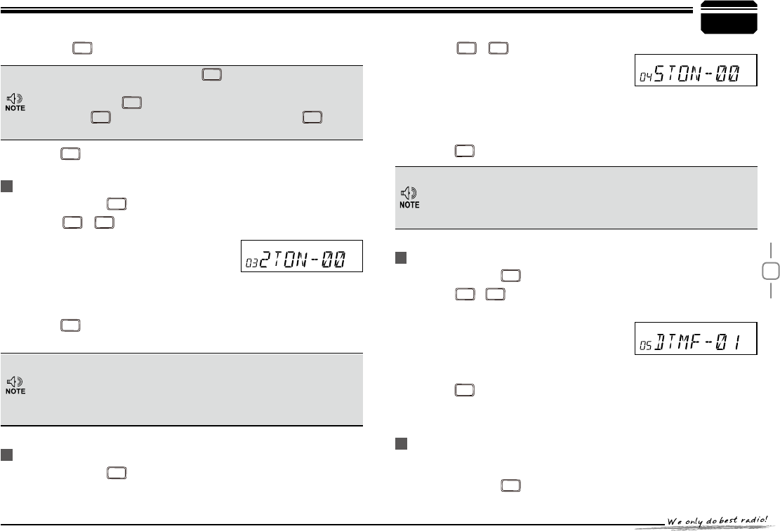
Press
2.
CALL
/
SCAN
key to choose No.04
menu, LCD displays "5TON XX", "XX"
indicates the group in the list.
Turn selector knob to select the desired sending 5TONE group,
3.
Press PTT to transmit selected group.
Total:100groups, 00-99, Default:00.
4.
Press
5.
TX/DCS
NH\WRFRQ¿UPDQGH[LW
General Setting
Content and name of 5TONE will be edited by programming
software. This radio only query edited group or name. If there
is corresponding name for 5TONE, this operation will display
5TONE corresponding name.
Press
CALL
directly to transmit the pre-stored 5-Tone signaling.
In 5Tone signaling mode, press
CALL
for 2s until LCD displays
"AN---", turn selector knob to select desired digit(caller ID). In
this mode, press
TX/DCS
to confirm exist digit and move cursor to
next, press
V/M
to forward cursor.After editing, press
CALL
key to
operate ANI call.
Press
4.
TX/DCS
NH\WRFRQ¿UPDQGH[LW
Sending 2-Tone Call
Press and hold
1.
FUNC
key for over 2s to enter general setting menu.
Press
2.
CALL
/
SCAN
key to choose No.03
menu, LCD displays "2TON XX", "XX"
indicates the group in the list.
Turn selector knob to select the desired
3.
sending 2TONE group, Press PTT to transmit selected group.
Total: 32groups, 00-31, Default: 00.
4.
Press
5.
TX/DCS
NH\WRFRQ¿UPDQGH[LW
Content and name of 2TONE will be edited by programming
software.
This radio only query edited group or name. If there is
corresponding name for 2TONE, this operation will display 2TONE
corresponding name.
Press and hold
1.
FUNC
key for over 2s to enter general setting menu
Sending DTMF call
Press and hold
1.
FUNC
key for over 2s to enter general setting menu.
Press
2.
CALL
/
SCAN
key to choose No.05 menu, LCD displays "'70)
XX", "XX" indicates the group in the list.
Turn selector knob to select the desired
3.
sending DTMF group, Press PTT to
transmit selected group.
Total: 16groups, 00-16, Default: 00.
4.
Press
5.
TX/DCS
NH\WRFRQ¿UPDQGH[LW
Signaling Combination setup
This function is to improve the level of protecting the radio against
receiving irrelative signal.
Press and hold
1.
FUNC
key for over 2s to enter general setting menu.
20
8
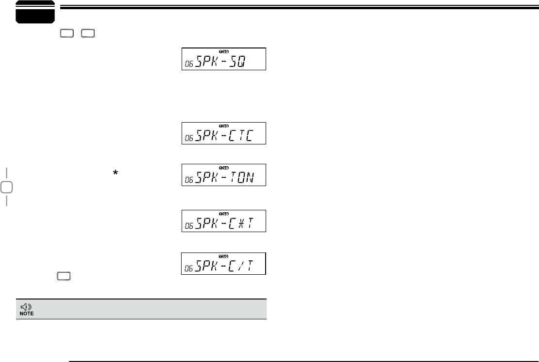
If select "SQ", it indicates you can hear
the calling from caller when receive a matching carrier.
If LCD displays "
CTC", it indicates you can hear the calling
from caller when receive a matching carrier and CTCSS/DCS
signaling.
If LCD displays "
TON", it indicates
you can hear the calling from caller
when receive a matching carrier and
DTMF/2TONE/5TONE signaling.
If LCD displays "
C T", it indicates
you can hear the calling from
caller when receive a matching
carrier and CTCSS/DCS and
DTMF/2TONE/5TONE signaling.
If LCD displays "
C/T", it indicates
you can hear the calling from
caller when receive a matching
carrier and either CTCSS/DCS and
DTMF/2TONE/5TONE signaling.
Press
4.
TX/DCS
NH\WRFRQ¿UPDQGH[LW
General Setting
Press
2.
CALL
/
SCAN
key to choose No.06
menu, LCD displays "SPK--SQ".
Turn selector knob to select the desired
3.
combination.
This setting will be set together with adding optional signaling
and CTCSS/DCS.
21
8
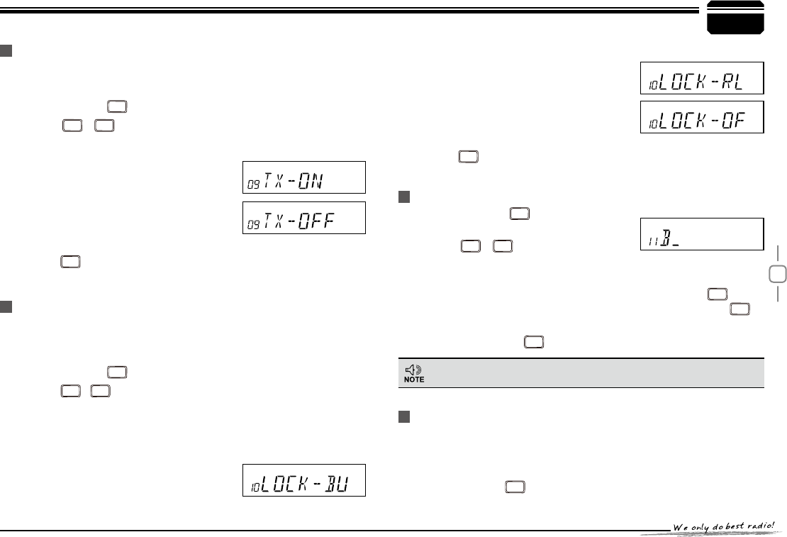
TX OFF SETUP
Disable this function, it is invalid to press PTT, current channel only
works in RX mode.
Press and hold
1.
FUNC
key for over 2s to enter general setting menu.
Press
2.
CALL
/
SCAN
key to choose No.09 menu, LCD displays "TX-
ON".
Turn selector knob to select the desired
3.
setting.
21In current channel, Press PTT to
transmit.
2))In current channel, Press PTT is
invalid.
Press
4.
TX/DCS
NH\WRFRQ¿UPDQGH[LW'HIDXOW21
Busy Channel Lockout
BCLO is to disable transmitting while RX signal is received. Once the
channel is busy and you press PTT, the radio will beep as warning and
get back to receiving.
Press and hold
1.
FUNC
key for over 2s to enter general setting menu.
Press
2.
CALL
/
SCAN
key to choose No.10 menu, LCD displays "LOCK-
2))".
Turn selector knob to select the desired setting.
3.
BU: Enable
BCLO, Carrier lockout, transmitting is inhibited when
current channel receives a matching carrier; press [PTT] to
emit error voice prompt and back to
receiving status.
RL: Enable
BTLO, transmitting is inhibited when current channel
receives a matching carrier but dis-
matching CTCSS/DCS. Press [PTT]
to emit error voice prompt and back to
receiving status.
OFF:
Busy channel lockout is disabled.
It can transmit in any receiving status.
Press
4.
TX/DCS
NH\WRFRQ¿UPDQGH[LW
Press and hold
1.
FUNC
key for over 2s to
enter general setting menu.
Press
2.
CALL
/
SCAN
key to choose No.11
menu, LCD displays cursor and
ÀDVKLQJ
Turn selector knob to select the desired letter, press
3.
TX/DCS
key to
confirm selected letter and enter into next edition, Press
V/M
to
return forward edition.
After edition, press
4.
TX/DCS
key to exit.
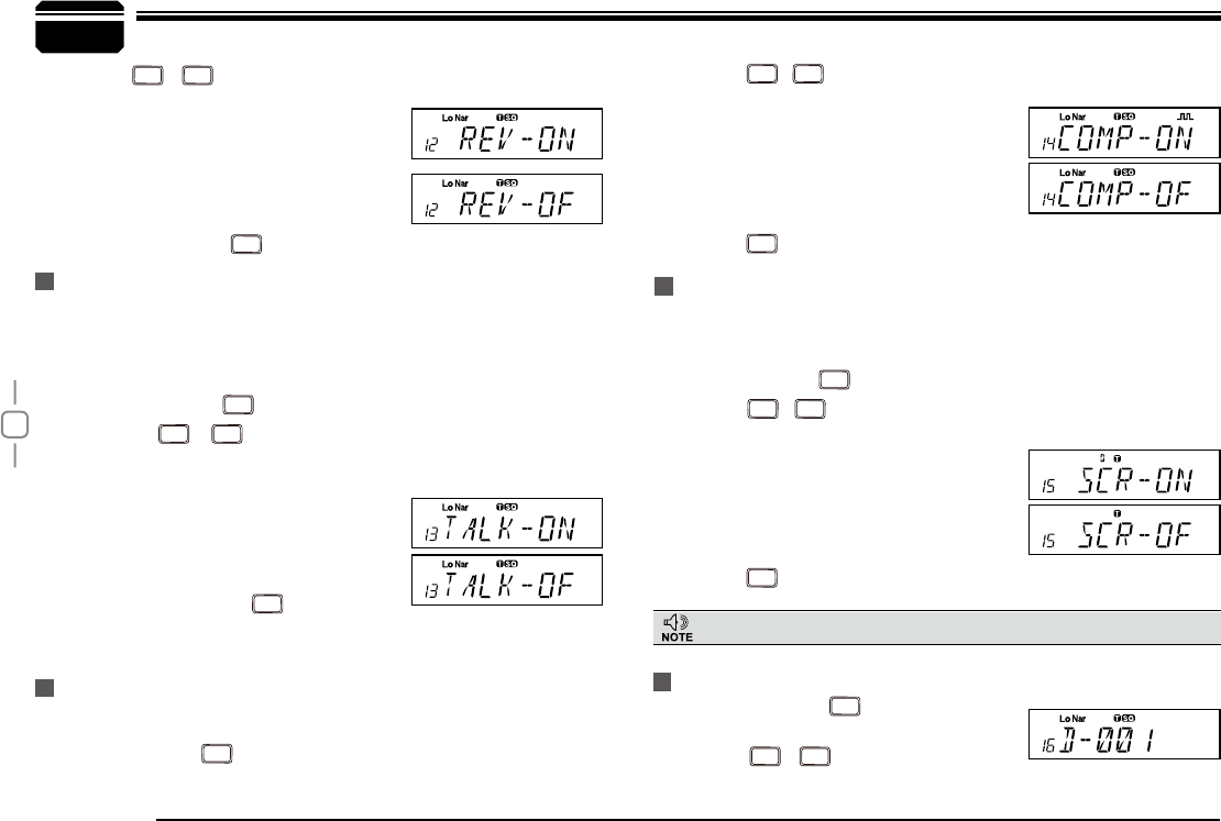
Reverse TX/RX
General Setting
Editing Channel NAME
In Frequency (VFO) mode, this function will be auto-hidden.
TX frequency turns to RX frequency & RX frequency changes to TX
frequency. The signaling will also be reversed if CTCSS/DCS signaling
exited in this channel.
Press and hold
1.
FUNC
key for over 2s to enter general setting menu
22
8
Press
2.
CALL
/
SCAN
key to choose No.12
menu, LCD displays "5(9²2)".
Turn selector knob to select the desired
3.
setting.
21Enable Frequency Reverse
2))Disable Frequency Reverse.
After edition, press
4.
TX/DCS
key to exit.
Talk Around
Press
2.
CALL
/
SCAN
key to choose No.14 menu, LCD displays "COMP-
2)".
Turn selector knob to select the desired
3.
setting.
21 Enable compander
2))Disable compander
Press
4.
TX/DCS
NH\WRFRQ¿UPDQGH[LW'HIDXOW2))
Scrambler setup (Encryption)
An analog voice inversion scrambler can be equipped as optionals. This
special audio process can offer a more confidential communication.
Other radios at same frequency will receive only disordered noises.
General Setting
By Talk Around function, you can directly communicate with other radios
in your group in case the repeater is not activated or when you are out of
the repeater range. The transceiver will transmit by RX frequency with its
CTCSS/DCS signaling.
Press and hold
1.
FUNC
key for over 2s to enter general setting menu.
Press
2.
CALL
/
SCAN
key to choose No.13 menu, LCD displays
"7$/.²2)".
Turn selector knob to select the
3.
desired setting.
21Enable Talk Around
2))Disable Talk Around
After edition, press
4.
TX/DCS
key to exit.
Voice Compander
Enable this function to reduce background noise and enhance audio
clarity, especially in long range communication.
Press and hold
1.
FUNC
key for over 2s to enter general setting menu
Radio's DTMF SELF ID ENQUIRY
This function is optional.
Press and hold
1.
FUNC
key for over 2s to
enter general setting menu.
Press
2.
CALL
/
SCAN
key to choose No.16
Press and hold
1.
FUNC
key for over 2s to enter general setting menu.
Press
2.
CALL
/
SCAN
key to choose No.15 menu, LCD displays "SCR--
2)".
Turn selector knob to select the desired
3.
setting.
21Enable Scrambler
2))Disable Scrambler
Press
4.
TX/DCS
NH\WRFRQ¿UPDQGH[LW'HIDXOW2))
23
8
menu, LCD displays "D--XXX", "XXX" is radio's DTMF SELF ID.
Press
3.
TX/DCS
NH\WRFRQ¿UPDQGH[LW
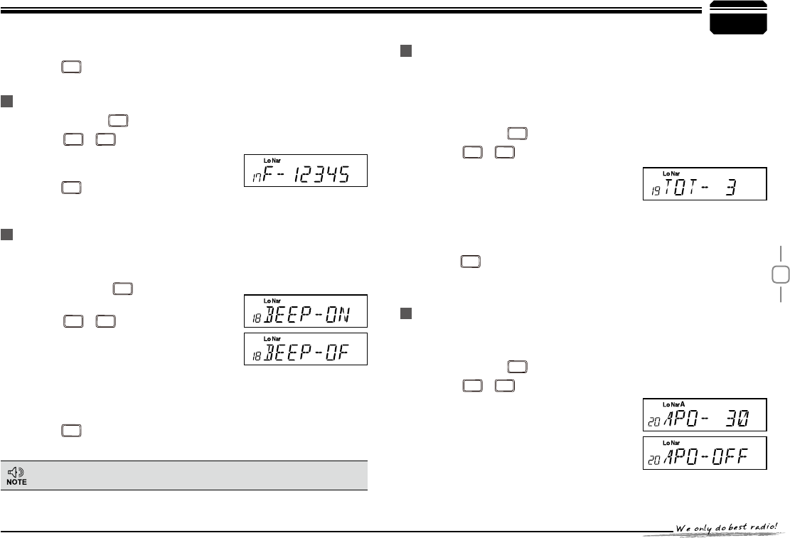
Radio's 5TONE SELF ID ENQUIRY
Press and hold
1.
FUNC
key for over 2s to enter general setting menu.
Press
2.
CALL
/
SCAN
key to choose No.17
menu, LCD displays "F--XXXXX",
"XXXXX" is radio's 5TONE SELF ID.
Press
3.
TX/DCS
NH\WRFRQ¿UPDQGH[LW
Voice Prompt
The prompting tone provides confirmation of entry, error status or
malfunctions of the transceiver. You can enable or disable this function.
Press and hold
1.
FUNC
key for over 2s to
enter general setting menu.
Press
2.
CALL
/
SCAN
key to choose No.18
menu, LCD displays "BEEP--ON".
Turn selector knob to select the desired
3.
setting.
21Enable voice prompt
2))Disable voice prompt
Press
4.
TX/DCS
NH\WRFRQ¿UPDQGH[LW'HIDXOW21
TOT (Time-out timer)
The time-out timer limits the amount of transmitting time. When you
reach the time limit which has been programmed by your dealer, your
transmission will be cut off. In order to transmit again, you must release
PTT button to reset the timer.
Press and hold
1.
FUNC
key for over 2s to enter general setting menu.
Press
2.
CALL
/
SCAN
key to choose No.19
menu, LCD displays "TOT--3".
Turn selector knob to select the desired
3.
setting.
7LPHU1-30min, each level 1min
2))Disable TOT
Press
4.
TX/DCS
NH\WRFRQ¿UPDQGH[LW'HIDXOW
APO (Auto power off)
Once APO is activated, the radio will be automatically switched off when
the pre-set timer is running to end.
Press and hold
1.
FUNC
key for over 2s to enter general setting menu.
Press
2.
CALL
/
SCAN
key to choose No.20
menu, LCD displays "$322))".
Turn selector knob to select the desired
3.
setting.
0,1Auto power off after 30m
+285Auto power off after 1h
General Setting
Suggestion:Enable this function to check incorrect operation and
malfunctions.
24
8
+285Auto power off after 2h
2))Disable Auto power off
Press
4.
TX/DCS
NH\WRFRQ¿UPDQGH[LW'HIDXOW2))
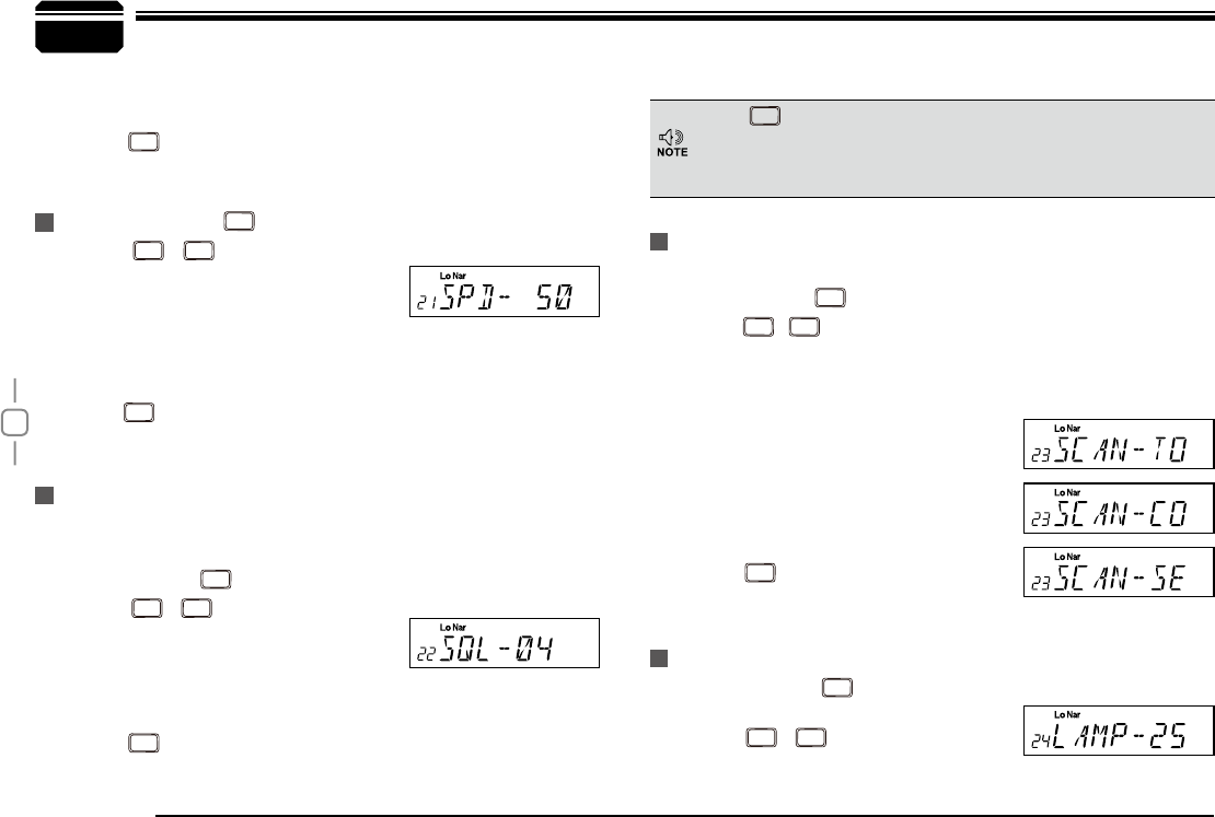
DTMF Transmitting Time
Press and hold
1.
FUNC
key for over 2s to enter general setting.
Press
2.
CALL
/
SCAN
key to choose No.21
menu, LCD displays "SPD--50".
Turn selector knob to select the desired
3.
setting.
30/50/100/200/300/500, which indicates the time for sending each
DTMF signal & the interval between each DTMF being sent.
Press
4.
TX/DCS
NH\WRFRQ¿UPDQGH[LW'HIDXOW06
Squelch level Setup
Setting the radio to a tight squelch level, you can avoid unwanted
signals or noise, but you may not receive a weak signal. Therefore, it will
be better for you to select the normal squelch level
Press and hold
1.
FUNC
key for over 2s to enter general setting menu.
Press
2.
CALL
/
SCAN
key to choose No.22
menu, LCD displays "SQL--04".
Turn selector knob to select the desired
3.
squelch level.
OF-20 total 21, OF is min setting value(ON)
Press
4.
TX/DCS
NH\WRFRQ¿UPDQGH[LW'HIDXOW
Scan Dwell Time Setup
There are 3 kinds of Scan Dwell Time for option.
Press and hold
1.
FUNC
key for over 2s to enter general setting menu.
Press
2.
CALL
/
SCAN
key to choose No.23 menu, LCD displays "SCAN-
-TO".
Turn selector knob to select the desired Scan Dwell Time.
3.
72It pauses 15s once scanning a
matching signal, then resume scan.
&2It pauses once scanning a matching
signal, signal disappeared then resume
scan.
6(It stops once scanning a matching
signal.
Press
4.
TX/DCS
NH\WRFRQ¿UPWKHVHOHFWLRQ
and exit.Default:TO.
LCD Backlight
Press and hold
1.
FUNC
key for over 2s to
enter general setting menu.
Press
2.
CALL
/
SCAN
key to choose No.24
menu, LCD displays "LAMP--25".
General Setting
Press
SCAN
, then turn selector knob also can select the desired
squelch level.
If the transceiver has set at higher squelch level, it may fail to hear
the calling. If set at lower squelch level, the radio will be interfered.
25
8
Turn selector knob to select the desired LCD backlight brightness
3.
1-32 total 32 level backlight brightness.
Press
4.
TX/DCS
NH\WRFRQ¿UPDQGH[LW'HIDXOW
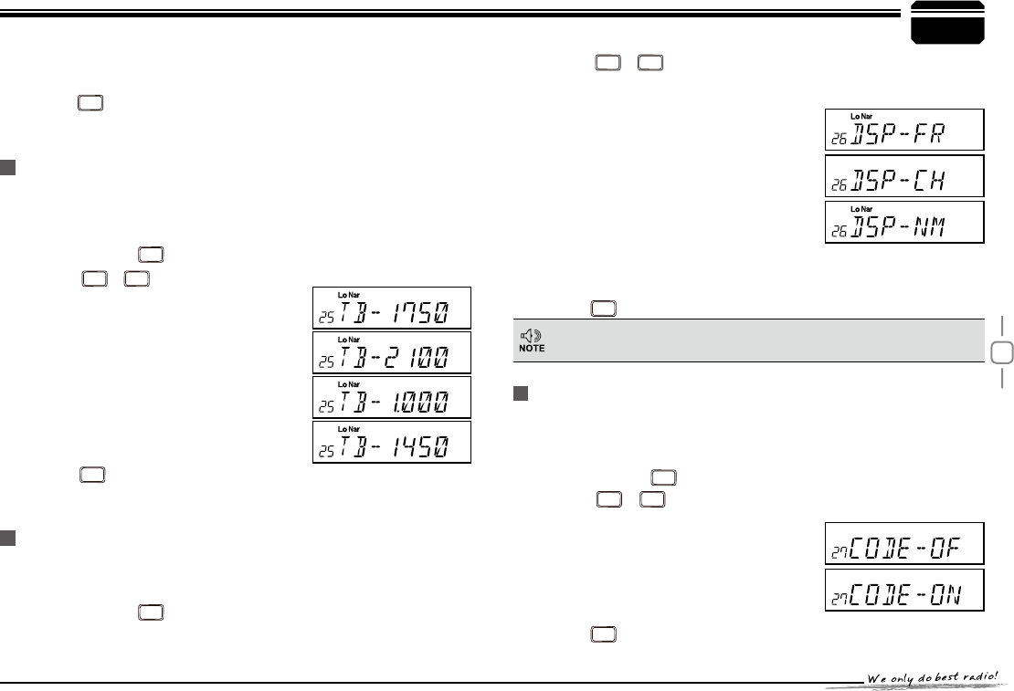
Pilot Frequency
This function uses to start repeater. It needs a certain intensity Pilot
Frequency to start dormant repeater. As usual, no need to send pilot
frequency again once repeater started.
Press and hold
1.
FUNC
key for over 2s to enter general setting.
Press
2.
CALL
/
SCAN
key to choose No.25
menu, LCD displays "TB--1750".
Turn selector knob to select the desired
3.
pilot frequency.
+=Pilot frequency1750HZ
+=Pilot frequency 2100HZ
+=Pilot frequency 1000HZ
+=Pilot frequency 1450HZ
Press
4.
TX/DCS
NH\WRFRQ¿UPWKHVHOHFWLRQ
and exit. Default:1750HZ
Display Mode Setup
There are 3 different dispaly modes: Frequency+Channel mode, &
Channel mode&Channel+Name Tag mode.
Press and hold
1.
FUNC
key for over 2s to enter general setting menu.
Press
2.
CALL
/
SCAN
key to choose No.26 menu, LCD displays
"'63²)5".
Turn selector knob to select the desired
3.
mode.
)5Frequency+Channel mode(Amateur
transceiver mode).
&+Channel mode(Professional
transceiver mode).
10Channel+Name Tag mode(Amateur
transceiver mode), if channel not
named, it displays Frequency+Channel
mode.
Press
4.
TX/DCS
NH\WRFRQ¿UPDQGH[LW'HIDXOW)5
PIN Setup
Enable this function, you have to insert a matching PIN to enter into
normal status when radio is turned on.(Pin setup by programme
software).
Press and hold
1.
FUNC
key for over 2s to enter general setting menu.
Press
2.
CALL
/
SCAN
key to choose No.27 menu, LCD displays
"&2'(2)".
Turn selector knob to enable/disable
3.
Pin setup.
21 Turn on Pin setup
2))Turn off Pin setup
Press
4.
TX/DCS
NH\WRFRQ¿UPDQGH[LW'HIDXOW2))
This function will be auto-hidden if channel mode locked.(Refer to
programme software)
General Setting
26
8
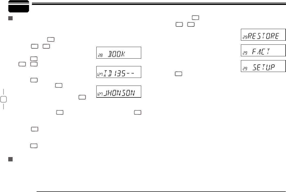
Address list
You store desired ID and corresponding ID name in address list. The
LCD displays ID corresponding name if radio received ANI calling and
¿QGPDWFKLQJ,'LQDGGUHVVOLVW
Factory Default
If your radio seems to be malfunctioning, resetting the microprocessor
may solve the problem. When performing the reset, you may lose
memory data and stored information. Back up or write down important
data before performing the reset.
General Setting
Press and hold
1.
FUNC
key for over 2s to enter general setting menu.
Press
2.
CALL
/
SCAN
key to choose No.29
menu, LCD displays "RESTORE".
Turn selector knob to select the desired
3.
operation.
FACT:Resume factory default for
channel, signaling and general setting.
SETUP:Return initial setup for No.18-
No.27 general setting menu.
Press
4.
MHz
NH\WRFRQ¿UP
You can operate the transceiver by keypad or input desired frequency
Press and hold
1.
FUNC
key for over 2s to enter general setting menu.
Press
2.
CALL
/
SCAN
key to choose No.28
menu, LCD displays "BOOK".
Press
3.
MHz
to enter into ID setting, press
CALL
/
SCAN
to select the desired group
(00-127, total is 128 group ID).Turn
selector knob to select desired number,
press
TX/DCS
FRQ¿UPDQGPRYHFXUVRUWR
next edition, press
V/M
to clear out all
digits.
After finishing edition, press
4.
MHz
to
FRQ¿UPDQGHQWHULQWRHGLWLRQRIFXUUHQW
group's ID corresponding name.Turn selector knob to select
desired letter, press
TX/DCS
to move cursor to next edition, Press
MHz
to clear out all letters. 00-127, total 128 group ID and corresponding
ID name.
Press
5.
MHz
to confirm and return into main menu. Repeat above
Step 3 and Step 4 operations to edit multi-ID and corresponding ID
name.
Press
6.
TX/DCS
key to return into standby status.
27
9
or channel through the QHM-03 microphone (Note:In professional
transceiver mode, other keys are invalid except PTT, [ / ],
CALL
and
SCAN
).
Keypad Lock
Pull down the slide switch to lock position, the lamp is turned off and
all of keypads is not work except PTT switch.
Transmitting DTMF By Microphone KeyPAD
Switches between VFO and channel mode
In standby, press
FUNC
key to switch between channel mode and
Frequency mode (VFO).
Short Calling
In standby, press
CALL
to transmit the selected DTMF/2TONE/5TONE
in current channel.
7UDQVPLWWLQJ'70) &RGH:In standby, press
SCAN
, LCD displays
DTMF data and group. Press [ / ] key to select the
desired transmitting DTMF group, then Press PTT to transmit.
If no DTMF data in current group, LCD displays "EMPTY", press
SCAN
key again and input desired DTMF code by keypad, press PTT to
transmit and store DTMF data.
Squelch Level
In standby, press
1.
FUNC
, then press
MINI
, LCD displays "SQL" and
current squelch level.
Press
2. / WRDGMXVWWKHGHVLUHGVTXHOFK OHYHOSUHVV
FUNC
, then press
MINI
, turn selector knob also canDGMXVWWKH
desired squelch level.
3UHVVQXPEHUNH\WRFRQ¿UPDQGH[LW
3.
Optional signaling
In standby, press
FUNC
, then press
H
/
L
to add optional signaling, repeat
above operation to set DTMF, 2TONE or 5TONE signaling.
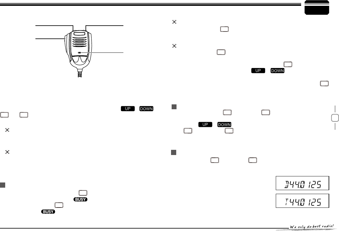
:KHQ¿UVWELWRI([DE\WHLQIUHTXHQF\
displays "D", it indicates DTMF
function enable.
:KHQ¿UVWELWRI([DE\WHLQIUHTXHQF\
displays "T", it indicates 2Tone
function enable.
Microphone Operation
Slide DTMF key to DTMF position, press and hold the [PTT] key,
transmitting the desired DTMF signaling by the numeric key directly.
(Note:Slide DTMF key to DTMF position, the keyboard is invalid in
standby).
Function Setup By Microphone Keypad
6TXHOFKRII:In standby, press
MINI
key,
the squelch is disabled when icon
ÀDVKHGLQ/&', Press
MINI
again to enable
squelch and the icon disappears.
$IBOOFM%PXO $IBOOFM61
.JD
155
28
9
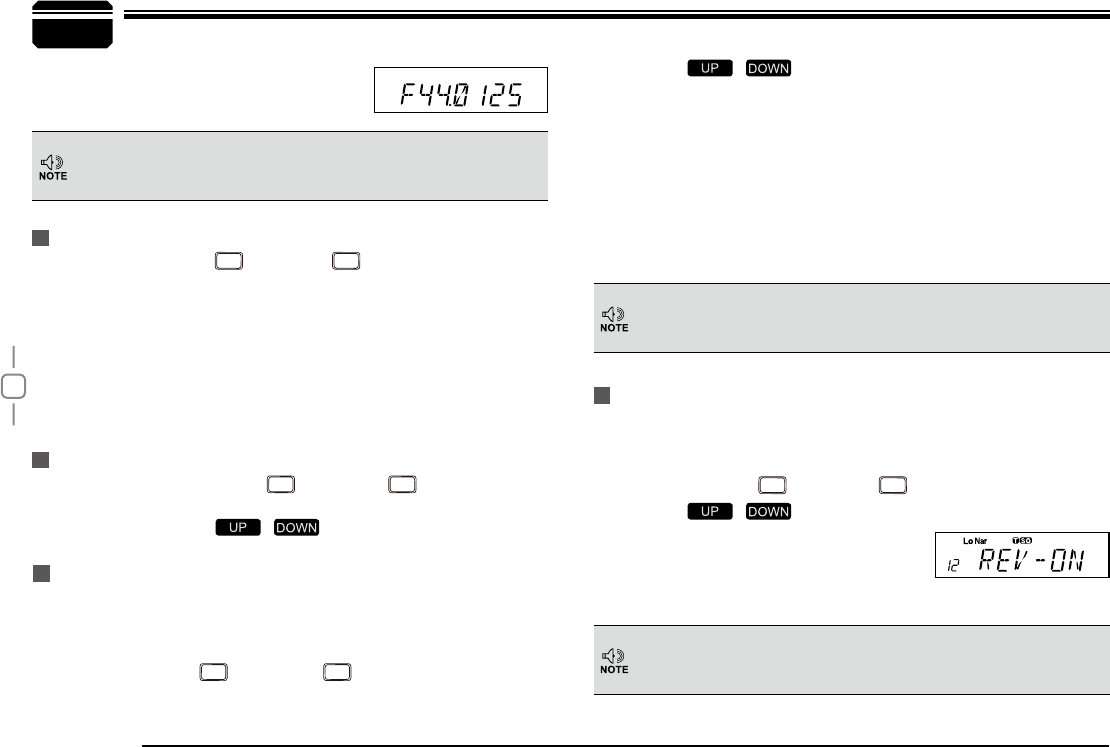
Reverse TX/RX
TX frequency turns to RX frequency & RX frequency changes to TX
frequency. The signaling will also be reversed if CTCSS/DCS signaling
exited in this channel.
In standby, press
1.
FUNC
, then press
MINI
, LCD displays "REV—ON".
Press [
2. / ] to select the desired value.
21Enable Frequency Reverse
2))Disable Frequency Reverse
3UHVVQXPEHUNH\VWRFRQ¿UPDQGH[LW
3.
In corresponding mode, press
FUNC
then press
MINI
key to enter into
scanning.
In scanning mode, press / to change scan direction.
Busy Channel Lockout
BCLO is to disable transmitting while RX signal is received. Once the
channel is busy and you press PTT, the radio will beep as warning and
get back to receiving.
In standby, press
1.
FUNC
, then press
MINI
to enter into Busy Channel
Lockout.
Press [
2. / ] to select the desired value.
%8 Enable BCLO, Carrier lockout, transmitting is inhibited when
current channel receives a matching carrier; press [PTT] to
emit error voice prompt.
5/ Enable BTLO, transmitting is inhibited when current channel
receives a matching carrier but dis-matching CTCSS/DCS.
Press [PTT] to emit error voice prompt It can transmit in any
receiving status.
2)) Busy channel lockout is disabled.
3UHVVQXPEHUNH\VWRFRQ¿UPDQGH[LW
3.
This function can be temporarily used in channel mode. Once the
radio is turned off or switched to another channel, the temporary
setting will be erased and back to initial settings.
Frequency/Channel scan
Scan Skip
:KHQ¿UVWELWRI([DE\WHLQIUHTXHQF\
displays ")", it indicates 5Tone function
enable.
This function can be temporarily used in Channel mode. Once the
radio is turned off or switched to another channel, the temporary
setting will be erased and back to initial settings.
This function can be temporarily used in Channel mode. Once the
radio is turned off or switched to another channel, the temporary
setting will be erased and back to initial settings.
Microphone Operation
In Channel mode, press
FUNC
then press
MINI
, decimal point displayed
between frequency's ten digit and unit digit, it means current channel is
scan skip. Repeat above operation to set scan or scan skip in current
channel.
decimal point displayed between frequency's ten digit and unit digit,
1.
it means current channel is scanned skip.
decimal point is not displayed between frequency's ten digit and
2.
unit digit, it means current channel is scanned.
29
9
TOT (Time-out timer)
The time-out timer limits the amount of transmitting time. When you
reach the time limit which has been programmed by your dealer, your
transmission will be cut off. In order to transmit again, you must release
PTT button to reset the timer.
In standby, press
1.
FUNC
, then press
MINI
LCD displays "TOT-X".
Press [
2. / ] to select the desired value.
3UHVVQXPEHUNH\WRFRQ¿UPDQGH[LW
3.
CTCSS/DCS Encode and Decode
In standby, press
1.
FUNC
, then press
MINI
to enter into CTCSS/DCS
Encode and Decode.
Repeat above operation to set as below:
2.
LCD displays
icon, it indicates CTCSS encode set in current
channel.
LCD displays
and icon, it indicates CTCSS encode and
decode set in current channel.
LCD displays
DCS icon, it indicates DCS encode and decode set
in current channel.
In corresponding icon, press [
3. / ] to select the desired
CTCSS/DCS encode and decode.
Press
4.
TX/DCS
or
SCAN
WRFRQ¿UPDQGH[LW
Talk Around
This function can be temporarily used in Channel mode. Once the
radio is turned off or switched to another channel, the temporary
setting will be erased and back to initial settings.
By Talk Around function, you can directly communicate with other radios
in your group in case the repeater is not activated or when you are out of
the repeater range. The transceiver will transmit by RX frequency with its
CTCSS/DCS signaling.
In standby, press
1.
FUNC
, then press
MINI
key, LCD displays "7$/.2)".
Press [
2. / ] to select the desired setting.
21Enable Talk Around
2))Disable Talk Around
3UHVVQXPEHUNH\WRFRQ¿UPDQGH[LW
3.
This function can be temporarily used in Channel mode. Once the
radio is turned off or switched to another channel, the temporary
setting will be erased and back to initial settings.
Voice Prompt
The prompting tone provides confirmation of entry, error status or
malfunctions of the transceiver. You can enable or disable this function.
In standby, press
1.
FUNC
, then press
V/M
, LCD displays "BEEP--XX".
Press [
2. / ] to turn on/off BEEP voice prompt.
%((3²2) turn off voice prompt
%((3²21 turn on voice prompt
Press number key to exit and store.
3.
Microphone Operation
30
9
LCD Backlight
In standby status, press
1.
FUNC
, then press
MINI
LCD displays
"LAMP-XX".
Press [
2. / ] to select desired backlight brightness(1-32
levels).
3UHVVQXPEHUNH\VWRFRQ¿UPDQGH[LW
3.
Microphone Operation
31
10
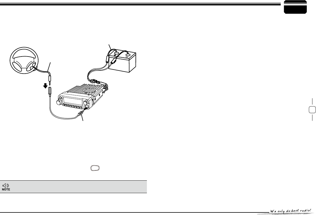
This function is mainly use for simple anti-theft alarm device in vehicles.
When the transceiver be removed in an improper manner, the transceiver
will emit and transmit alarming and background voice to system and
other transceiver of the same frequency.
Steering-wheel etc.
Alarm cable [QL-01(B)]
DC power cable
Battery
Alarm cable
[QL-01(A)]
Long-distance Anti-theft Alarm
Connect DC power cable with car battery.
&RQQHFWWKHRSWLRQDODODUPFDEOH4/$WR WKHGDWDMDFNRQ
1.
the front panel as shown. Secure the other end of the cable to an
REMHFWWKDWVWD\V¿[HGLQYHKLFOH1RWHLIDODUPFDEOH4/$LV
not enough long, you can choose optional alarm cable QL-01 (B) to
extend).
When transceiver power off by press
2.
PWR
key, the long-distance
anti-theft alarm enable.
When the alarm cable QL-01(A) or QL-01(B) is removed from the
3.
'$7$MDFNRUFXWE\LPSURSHUVHTXHQFHWKHDODUPIXQFWLRQHQDEOH
and will alarm as programmed. In alarming, the transceiver will stop
alarm once receiving a matching signal. And alarm again when a
matching signal disappeared.
Restart radio to cancel anti-theft alarming.Reconnect with alarm
4.
cable and turn off radio, the system will return to alarm mode.
The long-distance anti-theft alarm only available when
transceiver power off.
-
L
E
N
N
A
H
U
-
VOL
PWR
FUNC
V/M
CALL
MHz
TX/DCS
H/L
SCAN
MINI
32
11
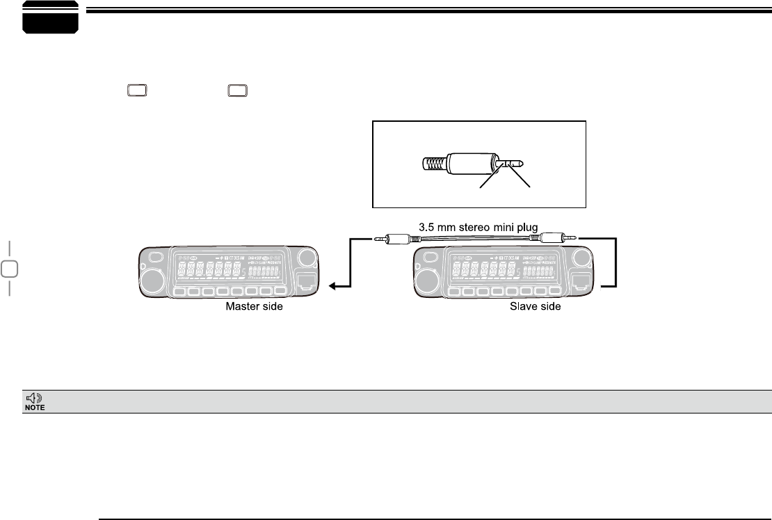
This feature will copy the programmed data and parameters in the master unit to slave units. It copies the parameters and memory program settings.
8VHRSWLRQDO&3FORQLQJFDEOHFRQQHFWWKHFDEOHEHWZHHQWKHGDWDMDFNVRQERWKPDVWHUDQGVODYH
1.
Press and hold
2.
FUNC
key, then press key to enter into cloning mode, LCD displays "CLONE".
Press master unit's [PTT] key, LCD displays "
3. SD XXX", "XXX" indicates data volume in transmitting. Slave unit displays "LD XXX", "XXX"
LQGLFDWHVUHFHLYHGGDWDYROXPH:KHQWKHWUDQVPLVVLRQLVVXFFHVVIXOO\¿QLVKHGWKHPDVWHUDQGVODYHXQLWERWKGLVSOD\PASS". Turn off the power,
disconnect the cable and repeat step 2 to step 3 operations to clone the next slave unit.
Cable Clone
If the data is not successfully transmitted, turn off both units, make sure the cable connection is correct and repeat the entire operation from the beginning.
GND DATA TX/RX
Master/Slave stereo plug,3.5mm plug
CALL
PWR
FUNC
V/M
CALL
MHz
TX/DCS
SCAN
MINI
-
L
E
N
N
A
H
U
-
VOL
PWR
FUNC
V/M
CALL
MHz
TX/DCS
SCAN
MINI
-
L
E
N
N
A
H
U
-
VOL
CAL CAL
33
12
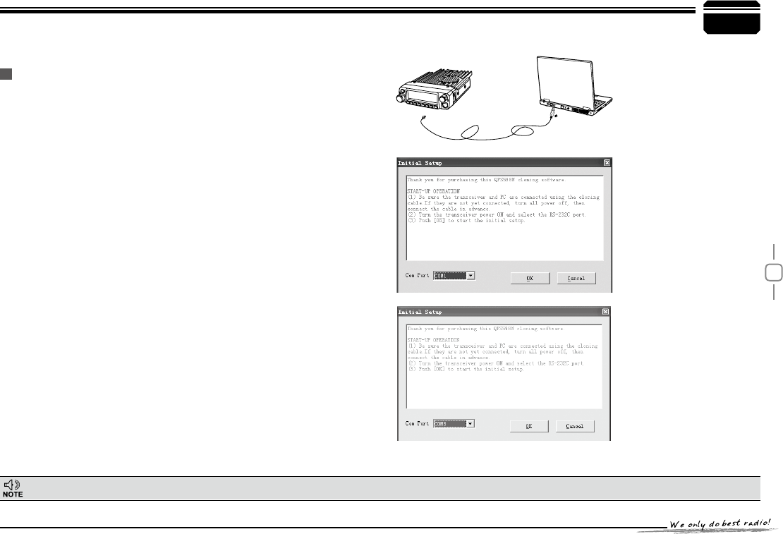
Programming Software Installing and Starting (in windows XP system)
Double click "QPS598 setup.exe", then follow the installing instruction.
7KLVVRIWZDUHKDVSURGXFWLGHQWLI\V\VWHPVRZKHQ¿UVWO\LQVWDOOLQJWKHVRIWZDUH\RXKDYHWRFRQQHFWWKHSURGXFWVRWKHUZLVH\RXFDQQRWVWDUWWKHVRIWZDUH
Install USB Cable Driver Programme
(As pic 1)
(As pic 2)
(As pic 3)
Click start menu in computer, under "ALL PROGRAMS" menu,
1.
choose and click "USB To Com port" in QPS598 program, install
"USB To Com port" driver by indication.
Connect the optional PC50 USB Programming cable to USB port in
2.
PC with transceiver.(As pic 1)
Double click QPS598 shortcut or click QPS598 in procedure index
3.
of start menu, choose serial com port as indicated then click OK to
start programming software. (As pic 2)
According to instruction, select correct "COM Port"(As pic 3), then
4.
click "OK" to start programming software.
1RWHEven in same computer, the selective COM Port is different when
USB cable connects with different USB port.
You shall install software before connecting the USB cable line. Switch
on transceiver before writing frequency. You had better not switch on or
off the power supply of transceiver when it is connected with computer,
otherwise, it will make transceiver unable to read or write frequency. In
this case, you have to turn off programming software, pull out USB cable.
then reinsert USB cable and open software, then rechoose COM Port,
it will turn into normal operation. Therefore, please connect transceiver
with computer after switching on the transceiver. Don't restart transceiver
power when it is connected with computer.
-
L
E
N
N
A
H
U
-
VOL
PWR
FUNC
V/M
CALL
MHz
TX/DCS
H/L
SCAN
MINI
34
13
AT598
DCS encode
and decode .
VFO frequency 145.00MHz DCS code 023N
Memory channel!0-199!. Output power HI
Offset direction . !!!!!!!!!!!!!! Key-lock setting OFF
Offset frequency 600KHz TOT OFF
Channel step 12.5KHz APO OFF
CTCSS encode and decode . !!!!!!!!!!!!! Squelch Level 4
CTCSS frequency 88.5Hz
Default Setting after Resetting(VHF) Trouble Shooting
Problem Possible Causes and Potential Solutions
D Power is on, nothing
appears on Display.
+ and - polarities of power connection
are reversed. Connect red lead to plus
terminal and black lead to minus terminal of
DC power supply.
E Fuse is blown. Check and solve problem resulting in blown
fuse and replace fuse with new fuse.
F Display is too dim. Dimmer setting is "LAMP-L". Please make the
dimmer setting "LAMP-H".
G No sound comes from
speaker.
6TXHOFKLVPXWHG'HFUHDVHVTXHOFKOHYHO
7RQHRUCTCSS/DCS squelch is active. Turn
CTCSS or DCS squelch off.
H Key and Dial do not
function.
Key-lock function is activated. Cancel Key-lock
function.
L Rotating Dial will not
change memory channel.
Transceiver is in CALL mode. Press the VFO
or memory mode.
J PTT key is pressed but
transmission does not occur.
0LFURSKRQHFRQQHFWLRQLVSRRU &RQQHFW
microphone properly.
$QWHQQDFRQQHFWLRQLVSRRU&RQQHFWDQWHQQD
properly.
Maintenance
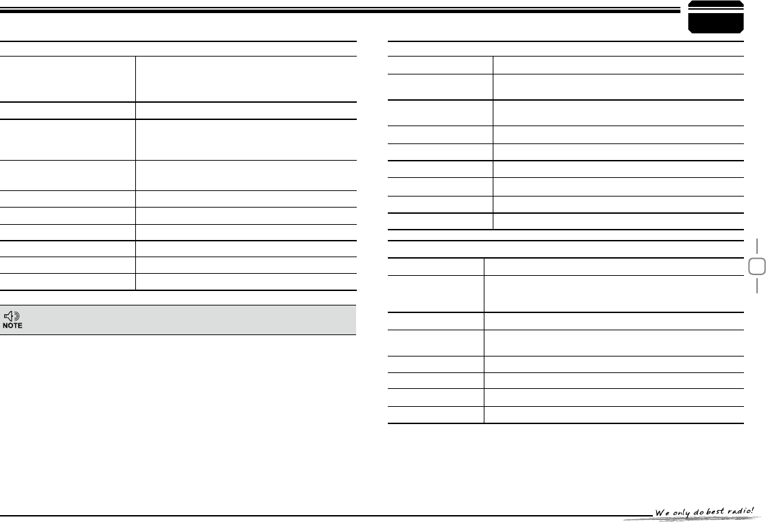
35
14
6SHFL¿FDWLRQVDUHVXEMHFWWRFKDQJHZLWKRXWQRWLFHGXHWRDGYDQFHPHQWVLQ
technology.
General
Frequency Range
Number of Channels
200 channels
Channel Spacing
Phase-locked Step
5KHz, 6.25KHz, 8.33KHz, 10KHz, 12.5KHz,
Operating Voltage 13.8V DC ±15%
Squelch
Carrier/CTCSS/DCS/5Tone/2Tone/DTMF
Frequency Stability ±2.5ppm
Operating Temperature
-20ą~+60ą
Dimensions(WxHxD) 145 (W) x 47 (H) x 190 (L)mm
Weight about 1.2Kg
5HFHLYHU(76,(1VWDQGDUGWHVWLQJ
Sensitivity
(12dB Sinad) ȝ9
$GMDFHQW&KDQQHO
Selectivity G%
Intermodulation G%
6SXULRXV5HMHFWLRQ G%
Audio Response +1~-3dB(0.3~2.55KHz)
Hum & Noise G%
Audio distortion
Audio power output Ὕ2W@10%
7UDQVPLWWHU(76,(1VWDQGDUGWHVWLQJ
Power Output 75W
Modulation .ĭ)(
$GMDFHQW&KDQQHO
Power G%
Hum & Noise G%
Spurious Emission G%
Audio Response +1~-3dB(0.3~2.55KHz)
Audio Distortion
Specifications
VHF: 136-174MHz
12.5K
band
band
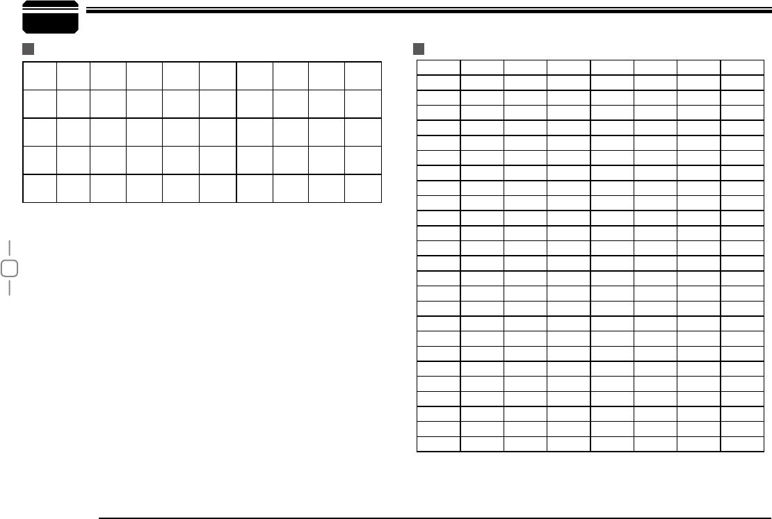
36
15
67.0 79.7 94.8 110.9 131.8 156.7 171.3 186.2 203.5 229.1
69.3 82.5 97.4 114.8 136.5 159.8 173.8 189.9 206.5 233.6
71.9 85.4 100.0 118.8 141.3 162.2 177.3 192.8 210.7 241.8
74.4 88.5 103.5 123.0 146.2 165.5 179.9 196.6 218.1 250.3
77.0 91.5 107.2 127.3 151.4 167.9 183.5 199.5 225.7 254.1
Attached Chart
50 groups CTCSS Tone Frequency(Hz) 1024 groups DCS Code.
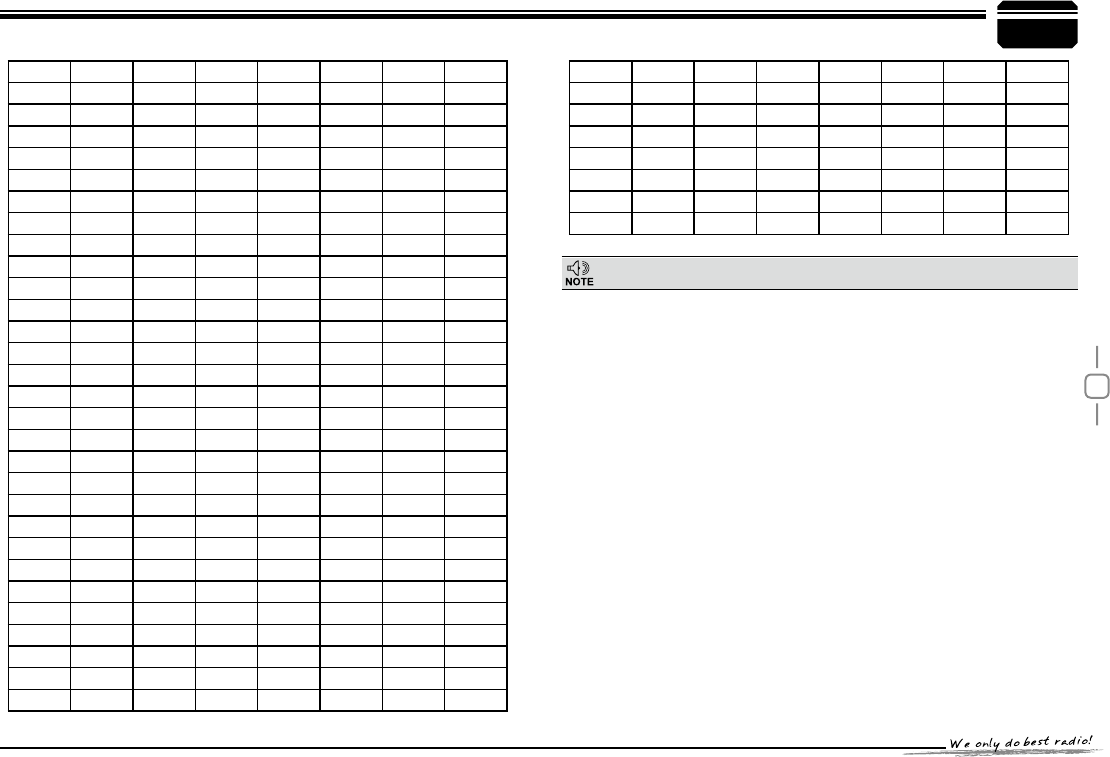
37
15
N is positive code, , is negative code, total: 232groups.
Attached Chart

SAFETYTRAININGINFORMATION
Your radiogeneratorsRFelectromagneticenergyduring
transmitmode.Thisradioisdesignedforandclassifiedas“OccupationalUseOnly”,meaningitmustbeusedonlyduringthe
courseofemploymentbyindividualsawareofthehazards,andthewaysToMinimizeSuchhazards.ThisradioisNOTintended
forusebythe“GeneralPopulation”inanuncontrolledenvironment.ThisradiohasbeentestedandcomplieswiththeFCCRF
exposurelimitsfor“OccupationalUseOnly”.Inaddition,your
radiocomplieswith
thefollowingStandardsandGuidelineswithregardtoRFenergyandelectromagneticenergylevelsandevaluationofsuch
levelsforexposuretohumans:
᪽
to Radio Frequency Electromagnetic Fields.
᪽American National Standards Institute (C95.1-1992), IEEE Standard for Safety Levels with Respect to Human
Exposure to Radio Frequency Electromagnetic Fields, 3 kHz to 300 GHz.
᪽American National Standards Institute (C95.3-1992), IEEE Recommended Practice for the Measurement of
Potentially Hazardous Electromagnetic Fields– RF and Microwave.
᪽The following accessories are authorized for use with this product. Use of accessories other than those (listed in the
instruction) specified may result in RF exposure levels exceed the FCC requirements for wireless RF exposure.
Toensureyou’reyourexposetoRFelectromagneticenergyiswithintheFCCallowablelimitsforoccupationaluse,always
adheretothefollowingguidelines
TheinformationlistedaboveprovidestheuserwiththeinformationneededtomakehimorherawareofRFexposure,
andwhattodotoasͲsurethatthisradiooperateswiththeFCCRFexposurelimitsofthisradio.
ElectromagneticInterference/Compatibility
Duringtransmissions, radiogeneratesRFenergythatcanpossiblycauseinterference
withotherdevicesorsystems.Toavoidsuchinterference,turnofftheradioinareaswheresignsarepostedtodoso.DONOT
operatethetransmitterinareasthataresensitivetoelectromagneticradiationsuchashospitals,aircraft,andblastingsites.
Occupational/ControlledUse
Theradiotransmitterisusedinsituationsinwhichpersonsareexposedasconsequenceoftheiremploymentprovided
thosepersonsarefullyawareofthepotentialforexposureandcanexercisecontrolovertheirexposure.
InordertocomplywithRFexposurerequirements,aminimumdistanceofmustbemaintainedbetweentheantenna
andallpersons
FCC OET Bulletin 65 Edition 97-01 Supplement C, Evaluating Compliance with FCC Guidelines for Human Exposure
76.6cm
Qixiang Electron Science & Technology Co.,Ltd.
Qixiang Electron Science & Technology Co.,Ltd.
Qixiang Electron Science & Technology Co.,Ltd.

6$)(7<75$,1,1* INFORMATION
:$51,1*
This radio generates RF electromagnetic energy during transmission.
This radio is designed for and classified as “Occupational Use Only”,
meaning it must be used only during the course of employment by
individuals aware of the hazards, and the ways to minimize such
hazards.This radio is NOT intended for use by the “GeneralPopulation”
in an uncontrolled environment.
For compliance with FCC and Industry Canada RF Exposure
Requirements, the transmitter antenna installation shall comply with the
following two conditions:
1.The transmitter antenna gain shall not exceed 0 dBi.
The antenna is required to be located outside of a vehicle and kept at
a distance of 76.6 centimeters or more between the transmitting
antenna of this device and any persons during operation.For small
vehicle as worst case, the antenna shall be located on the roof top at
any place on the centre line along the vehicle in order to achieve 76.6
centimeters separation distance. In order to ensure this distance
is met, the installation of the antenna must be mounted at least 76.6
centimeters away from the nearest edge of the vehicle in order to protect
against exposure to bystanders.
&$87,21
To ensure that your exposure to RF electromagnetic energy is within
the FCC allowable limits for occupational use, always adhere to the
following guidelines:
DO NOT operate the radio without a proper antenna attached, as
this may damage the radio and may also cause you to exceed FCC
RF exposure limits. A proper antenna is the antenna supplied with this
UDGLRE\WKHPDQXIDFWXUHURUDQDQWHQQD VSHFL¿FDOO\DXWKRUL]HGE\WKH
manufacturer for use with this radio.
DO NOT transmit for more than 50% during the time of employment
(50% duty cycle or less). Transmitting excessive amount of time can
cause RF exposure compliance requirements to be exceeded. Please
carefully read this instruction manual to learn how to transmit and stop
transmitting before starting to use it.
(OHFWURPDJQHWLF,QWHUIHUHQFH&RPSDWLELOLW\
During transmissions, your radio generates RF energy that can
possibly cause interference with other devices or systems. To avoid
such interference, turn off the radio in areas where signs are posted to
do so. DO NOT operate the transmitter in areas that are sensitive to
electromagnetic radiation such as hospitals, aircraft, and blasting sites.
2FFXSDWLRQDO&RQWUROOHG8VH
This product is used in situations that users are exposed to RF as
consequence of their employment provided those users are fully aware
of the potential RF hazards and can exercise control over their exposure.
This transceiver is NOT ATEX approved and NOT intended for the use
in hazardous explosive atmospheres.