Quake Global QLOCATE Short Burst Data Transceiver User Manual LOCATE Technical Data Sheet
Quake Global Inc. Short Burst Data Transceiver LOCATE Technical Data Sheet
UserManual.wiki
>
Quake Global
>
QLOCATE User Manual
Technical data sheet
Navigation menu
Upload a User Manual
Namespaces
Wiki Guide
HTML
PDF
Info
Views
User Manual
Discussion / Help
Navigation
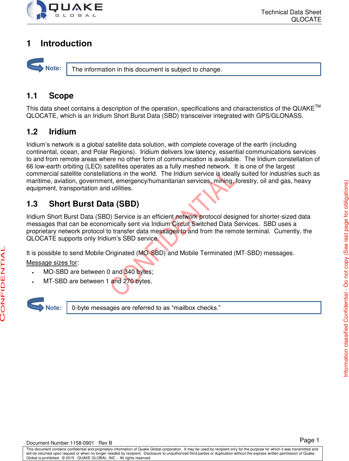
![Technical Data Sheet QLOCATE Document Number 1158-0901 Rev B This document contains confidential and proprietary information of Quake Global corporation. It may be used by recipient only for the purpose for which it was transmitted and will be returned upon request or when no longer needed by recipient. Disclosure to unauthorized third parties or duplication without the express written permission of Quake Global is prohibited. © 2015 QUAKE GLOBAL, INC. - All rights reserved. CONFIDENTIAL Information classified Confidential - Do not copy (See last page for obligations) Page 2 Related documents 1.4QUAKE QUAKE documentation can be obtained from the Downloads tab of QUAKE’s website or by contacting QUAKE Customer Support. Iridium The following Iridium documentation may be helpful: [1] Iridium SBD Developer’s Guide (QUAKE P/N: 4000-0713) [2] Iridium ISU AT Command Set (QUAKE P/N: REF-IRI-001) GPS The following GPS documentation may be helpful: [3] u-blox 7 Receiver Description (incl. Protocol version 14.00) (GPS.G7-SW-12001-B) Department of Defense (DoD) [4] MIL-STD-810E DoD Test Method Standard for Environmental Engineering Considerations and Laboratory Tests Evaluation Kits 1.5QLOCATE Evaluation Kits are available from QUAKE. They include: the QLOCATE modem, the data cable, all documentation, and air time. Contact your QUAKE sales representative for more details. Contacting QUAKE 1.6Quake Global, Inc. 4933 Paramount Dr San Diego, CA 92123 Phone: (858)-277-7290 Fax: (858) 277-7259 Website: www.quakeglobal.com Submit a Customer Support Ticket: http://quakeglobal.com/support/ Email: customersupport@quakeglobal.com](https://usermanual.wiki/Quake-Global/QLOCATE/User-Guide-2556554-Page-6.png)
![Technical Data Sheet QLOCATE Document Number 1158-0901 Rev B This document contains confidential and proprietary information of Quake Global corporation. It may be used by recipient only for the purpose for which it was transmitted and will be returned upon request or when no longer needed by recipient. Disclosure to unauthorized third parties or duplication without the express written permission of Quake Global is prohibited. © 2015 QUAKE GLOBAL, INC. - All rights reserved. CONFIDENTIAL Information classified Confidential - Do not copy (See last page for obligations) Page 9 The behavior of +CIEV:1 is identical to that of the Network Available output. 3.2 Serial data interface The serial data interface is an RS-232 9-wire interface at 3.3V digital signal levels (LVTTL) over which the QLOCATE and the customer solution transfer commands, responses, and SBD message data. In using this interface, the QLOCATE behaves as a DCE (Data Communication Equipment), and the customer solution behaves as a DTE (Data Terminal Equipment). If RS-232 voltage levels are needed, the customer solution must include an LVTTL/RS-232 level-shifter. Autobaud is not supported. The baud rate can be set via the AT+IPR command. The default rate is 19200 bps. The QLOCATE’s serial interface supports the control signaling of a 9-wire interface by default for those host applications that require it. However, the interface can also be configured for 3-wire operation – in which only transmit, receive and ground signals are used – with no detriment to functionality/performance. See the ISU AT Command Set for more information. 3.3 Network Available output Network Available is a digital output that can notify an application that the QLOCATE has visibility to the Iridium satellite network. This feature is helpful when the movement of the QLOCATE reduces the amount of time that it has a clear line of sight to the satellite. If the customer solution includes this logic output in the application decision logic, battery life can be preserved by thereby reducing the number of attempted transmissions. Network Available means only that the QLOCATE can successfully receive the Ring Channel (namely, it has an Iridium satellite in view). It is not a guarantee that a message can be successfully sent. The Network Available state is evaluated every time the Ring Channel is received, which is typically every 4 seconds if the Ring Channel is visible. If the Ring Channel is not currently visible, the update time can take as long as 2 minutes, depending on how long the lack of satellite visibility existed. The update time varies because the QLOCATE attempts to conserve power by increasing the Ring Channel search interval as long as the satellites are not in view. Every time a ring search fails, the time to wait is increased and eventually limits at 120 seconds. If Network Available is currently off, the customer solution may still attempt an SBDI[X] session. This will force the QLOCATE to look for the Ring Channel immediately and, upon finding it, to attempt to send the message. In this case, Network Available will not come on immediately. The Network Available does not turn on while in a +SBDI session. It will, however, turn on 4 seconds later due to the assumption that the Ring Channel is present. After the SBD session completes, the QLOCATE performs a new Ring Channel search, at the end of which Network Available is turned on. This can take between 4 and 12 seconds. The wait time between search windows is reset to 4 seconds every time a search succeeds. Otherwise, it continues to increase. Therefore, if the +SBDI attempt fails to find the Ring Channel, the search window does not reset to 4 seconds. 3.4 DC supply indicator output A DC supply indicator signal is provided which could be used directly for driving an LED to provide a visible indication that the QLOCATE’s supply is on. Alternatively, the output signal could be used in application logic to determine whether the internal transceiver power supply is on. Note:](https://usermanual.wiki/Quake-Global/QLOCATE/User-Guide-2556554-Page-13.png)
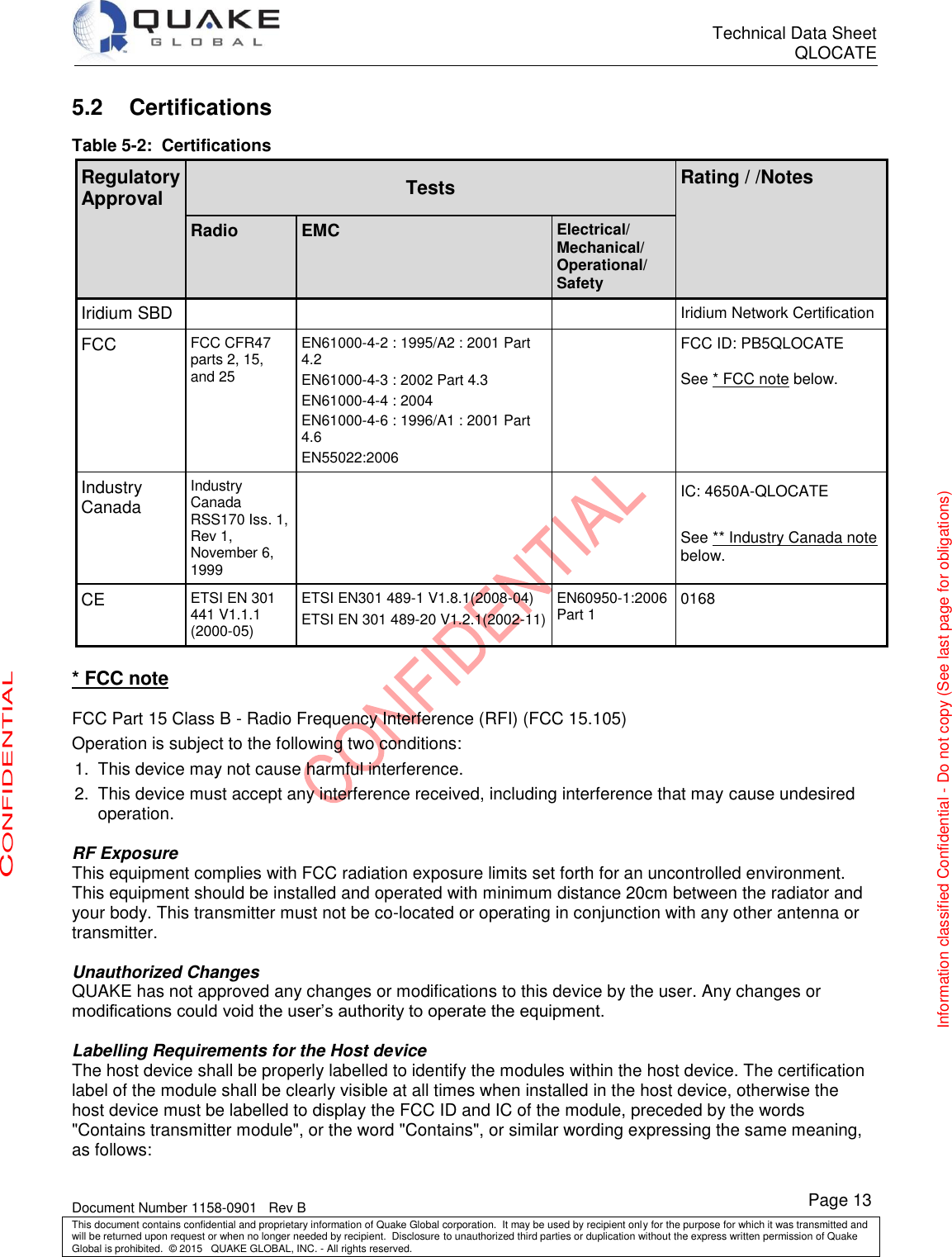

![Technical Data Sheet QLOCATE Document Number 1158-0901 Rev B This document contains confidential and proprietary information of Quake Global corporation. It may be used by recipient only for the purpose for which it was transmitted and will be returned upon request or when no longer needed by recipient. Disclosure to unauthorized third parties or duplication without the express written permission of Quake Global is prohibited. © 2015 QUAKE GLOBAL, INC. - All rights reserved. CONFIDENTIAL Information classified Confidential - Do not copy (See last page for obligations) Page 16 5.3 Declaration of Conformity DECLARATION OF CONFORMITY We, Quake Global, Inc. (previously Quake Wireless, Inc. up to January 2001) of 4933 Paramount Drive San Diego, CA 92123, USA declare under our sole responsibility that the product QLOCATE, part numbers 1158-5000 and 1158-5001 to which this declaration relates, is in conformity with the following standards and/or other normative documents: Article 3.1(a): Safety testing against EN/IEC60950-1 Article 3.1(a): RF Exposure calculation against EN 62311 Article 3.1(b): EMC testing against EN 301 489-1 referencing EN 301 489-20 Clause 9.2: RF Electromagnetic Field 80MHz – 2.7GHz: Clause 9.3: Electrostatic Discharge (Non Contact): Article 3.2 (Spectrum Usage): Iridium RF testing against EN 301 441: Clauses 4.2.1, 4.2.2, 4.2.3, 4.2.4, 4.2.5.1, 4.2.5.2, 4.2.5.3, 4.2.5.4.1, 4.2.5.4.2, 4.2.6 & 4.2.7 in the Iridium satellite 1.6MHz frequency band. Article 3.2(Spectrum Usage): GPS/GLONASS radiated emissions against EN 300 440 FCC 47CFR Part 15B / IC RSS-GEN (ICES-003) Radiated emissions only. FCC 47CFR Part 25 / IC RSS-170 Iridium RF testing FCC 47CFR Part 2.1091 / IC RSS-102 MPE RF Exposure calculation on 1.6GHz Iridium transmitter. Directive 2011/65/EC, RoHS2 We hereby declare that all essential radio test suites have been carried out and that the above named product is in conformity with all the essential requirements of Directive 1999/5/EC. The conformity assessment procedure referred to in Article 10 and detailed in Annex [IV] of Directive 1999/5/EC has been followed with the involvement of the following Notified Body: TUV SUD BABT TCB Octagon House, Segensworth Road, Fareham, Hampshire, PO15 5RL Identification mark: 0168 The technical documentation relevant to the above equipment will be held at: Quake Global, Inc. 4933 Paramount Drive San Diego, CA 92123 USA Andrew Singgih Director, Quality Assurance Signed: February 25, 2015](https://usermanual.wiki/Quake-Global/QLOCATE/User-Guide-2556554-Page-20.png)