Quanta Computer LM175 LTE M.2 Card User Manual
Quanta Computer Inc LTE M.2 Card Users Manual
Users Manual
Quanta LM175 Test Operation Guide
Version 0.1
Jun. 04, 2014
Robert

Page
1
Contents
1. Introduction .................................................................................................................................... 3
2. Test Environment ............................................................................................................................ 3
2.1. Uninstallation ......................................................................................................................... 3
2.1.1. Windows 7 (32 bit) ................................................................................................................. 3
2.2. Installation of drivers .............................................................................................................. 5
2.2.1. Windows 7 (32 bit) ................................................................................................................. 5
3. Operation of Connection Manager ................................................................................................. 11
3.1. Windows 7 (32 bit) ................................................................................................................ 11
3.1.1. Basic Configuration ................................................................................................................ 11
3.1.2. Extended Information ............................................................................................................13
3.1.3. LTE Manager ..........................................................................................................................15
3.1.4. Manual PLMN ........................................................................................................................16
3.1.5. Change to Commercial Mode .................................................................................................17
3.1.6. Disable Polling .......................................................................................................................18
3.1.7. PIN Management ...................................................................................................................19
3.1.8. Automatic Connect Mode ......................................................................................................20
3.1.9. Device Location .....................................................................................................................21
3.1.10. Help .......................................................................................................................................22
3.1.11. Reset .....................................................................................................................................23

Page
2
Revision History
Version Release Date Description
0.1 Jun. 04, 2014 1st Test Operation Guide Release
Page
3
1. Introduction
This document gives the guidance on how to test Quanta devices.
2. Test Environment
Quanta LM175 device supports Windows XP, Windows Vista (32 bit), and Windows 7 (32 bit) operating
system. It’s recommended to install Quanta LM175 software in Windows 7 32-bit OS.
2.1. Uninstallation
In order to install latest version of software, uninstallation of previous version is required, including
drivers, connection manager, and corresponding software tools.
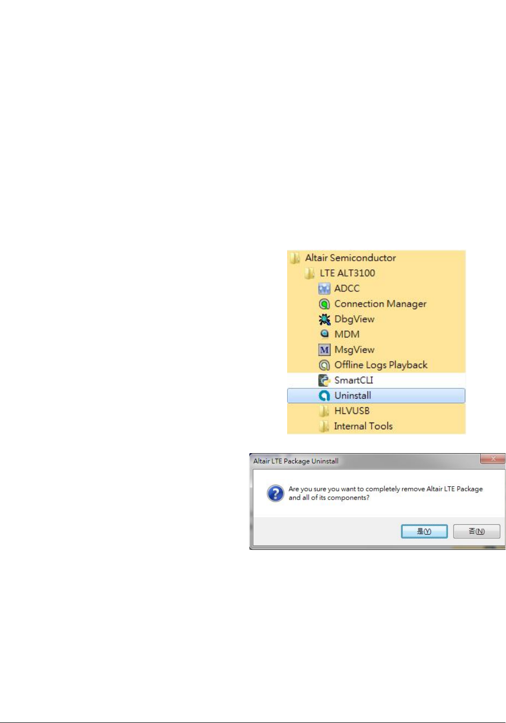
2.1.1. Windows 7 (32 bit)
1. Please click
StartProgramsAltair SemiconductorLTE
ALT3100Uninstall
2. Please click “Yes (Y)” button.
Page
4
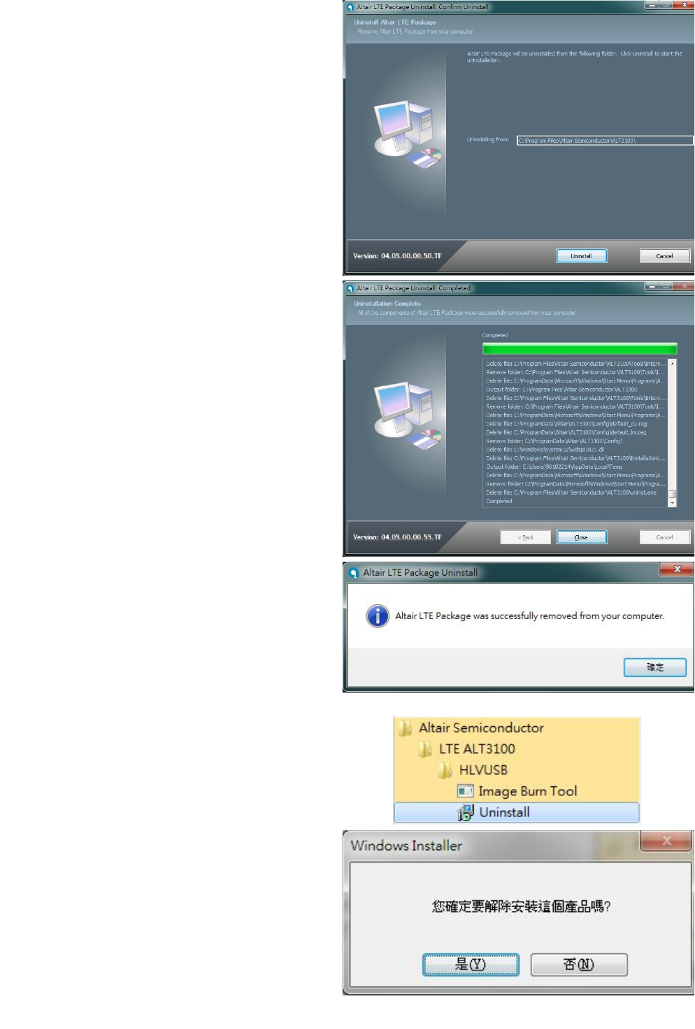
3. Please click “Uninstall” button.
4. Please wait a few seconds to complete
uninstallation.
5. Please click “Close” button.
6. Please click “OK” button.
7. Please click
“StartProgramsAltair SemiconductorLTE
ALT3100HLVUSBUninstall”.
8. Please click “YES (Y)” button.
9. Please reboot your computer after you have
completed the uninstallation.
Page
5
2.2. Installation of drivers
2.2.1. Windows 7 (32 bit)
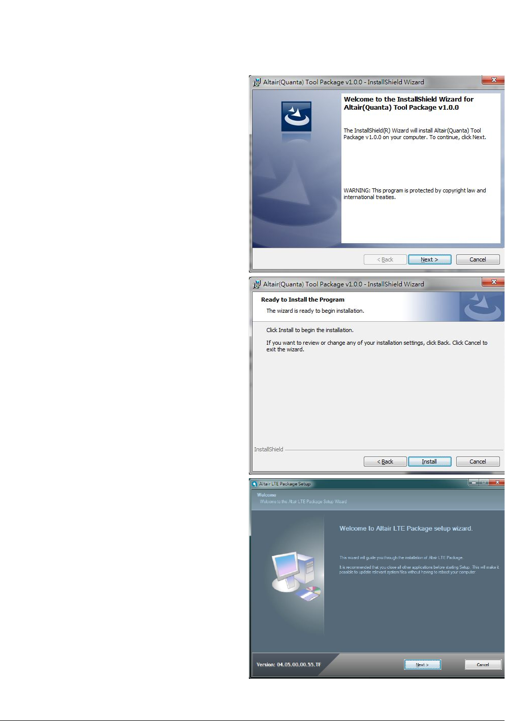
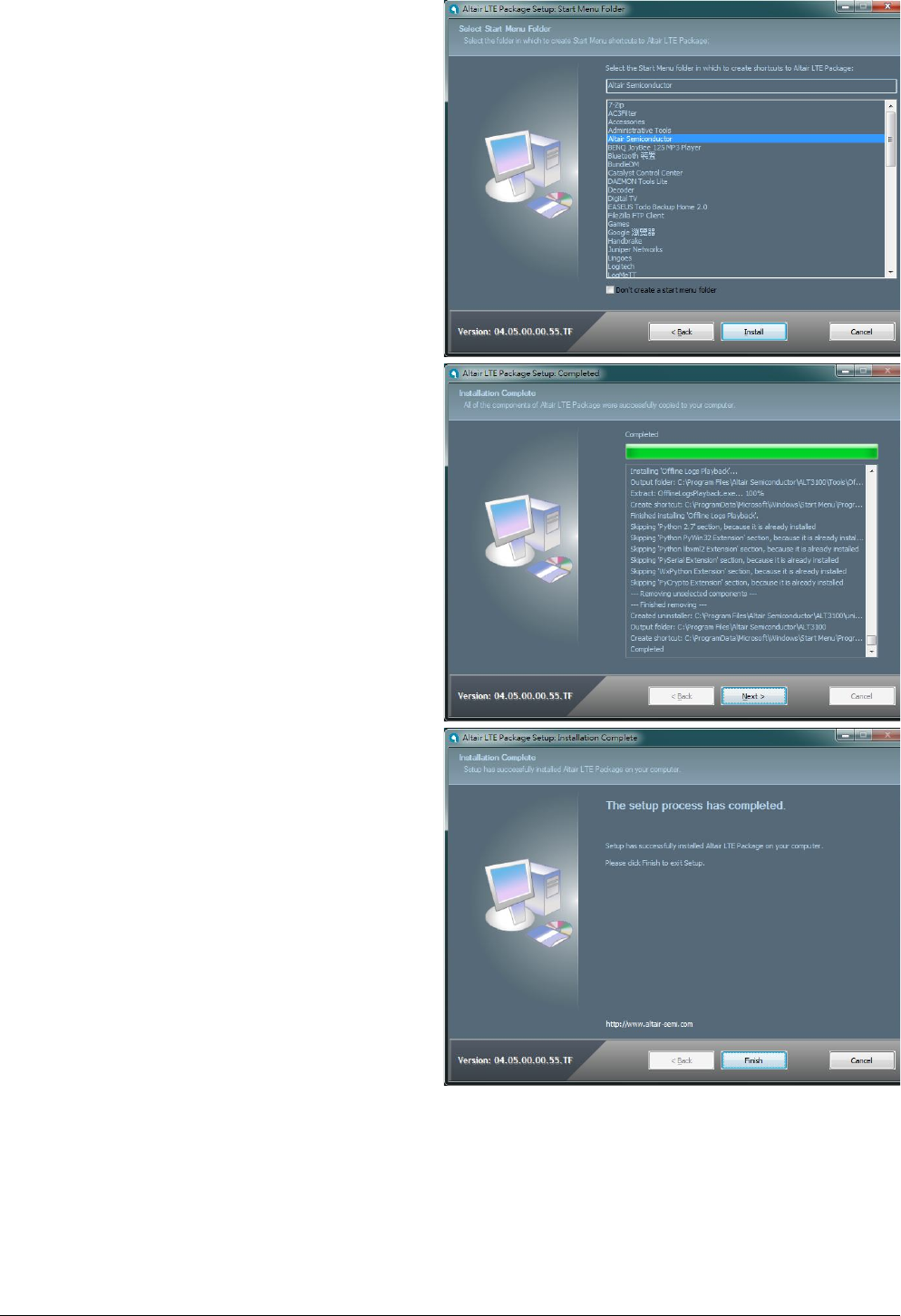
1. Please double clicks on “Altair(Quanta) Tool
Package v1.0.0.exe” to start installation.
2. Please click “Next >” button.
3. Please click “Install” button.
4. It will take a few minutes to complete
installation.
5. Please click “Next >” button.
Page
6
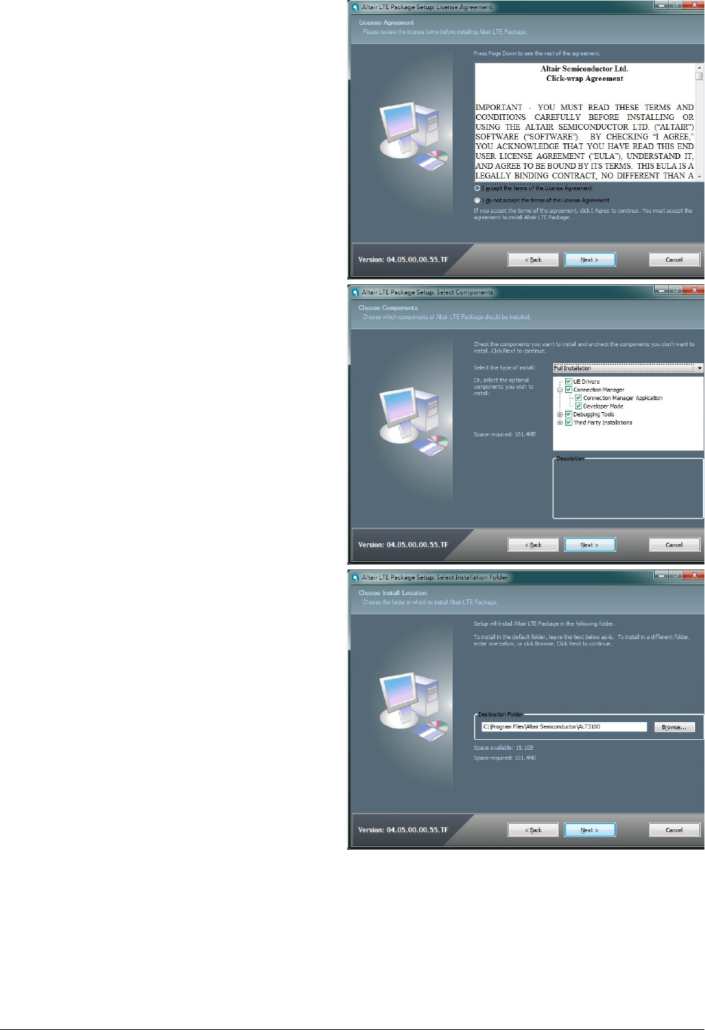
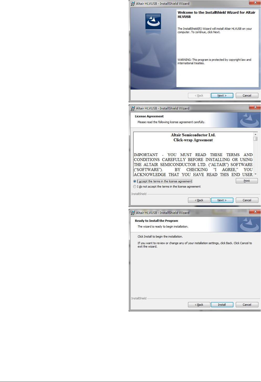
6. Please check “I accept the terms in the license
agreement”.
7. Please click “Next >” button.
8. Please select “Full Installation” type.
9. Please click “Next >” button.
10. Please click “Next >” button.
Page
7
11. Please click “Install” button.
12. Please click “Next >” button.
13. Please click “Finish” button.
Page
8
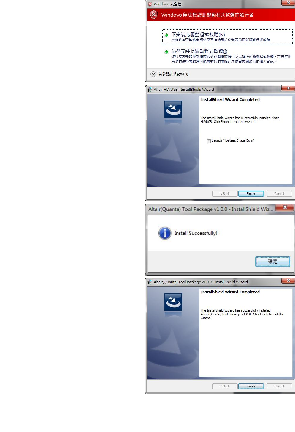
14. Please click “Next >” button.
15. Please check “I accept the terms in the license
agreement”.
16. Please click “Next >” button.
17. Please click “Install” button.
Page
9
18. Please click “Continue to install driver anyway
(I)”.
19. Please click “Continue to install driver anyway
(I)”.
20. Please click “Continue to install driver anyway
(I)”.
21. Please click “Continue to install driver anyway
(I)”.
22. Please un-check “Launch “Hostless Image
Burn””.
23. Please click “Finish” button to complete driver
installation.
24. Please click “OK” button.
25. Please click “Finish” button.
Page
10
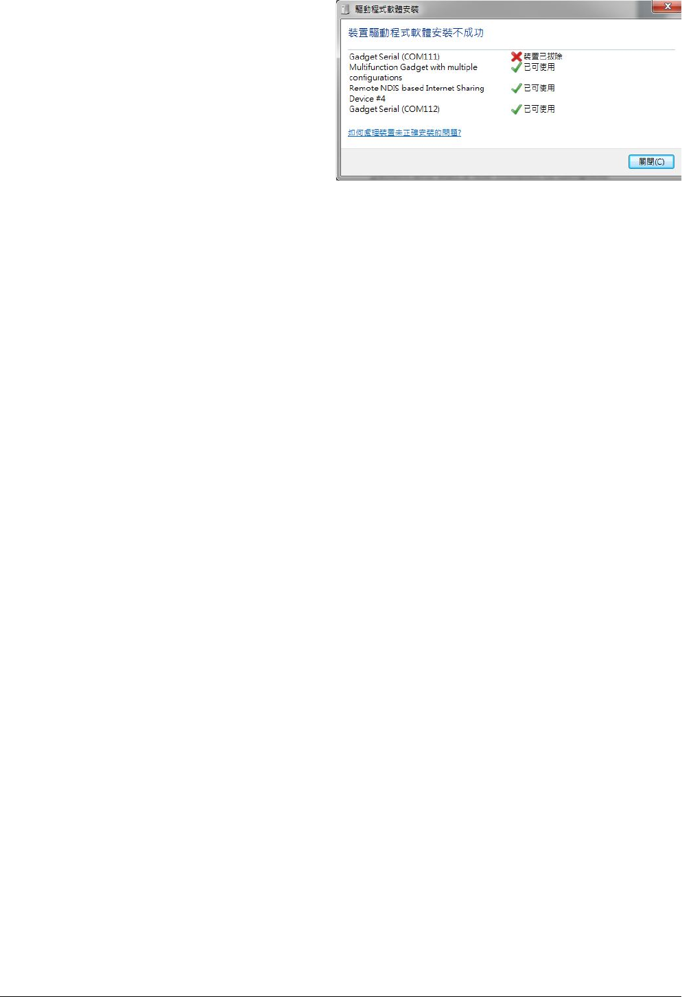
26. Please plug in Quanta device and please be
patient and wait a few minutes to complete
driver installation.
27. Please click “Close (C)” button.
28. Please reset Quanta device (take
out and plug in
the usb cable), it will take about 50 seconds for
Quanta embedded system to be ready.
Page
11
3. Operation of Connection Manager
3.1. Windows 7 (32 bit)
3.1.1. Basic Configuration
1. In order to get information from our
embedded connection manager, it’s
mandatory to configure as the following
instructions.
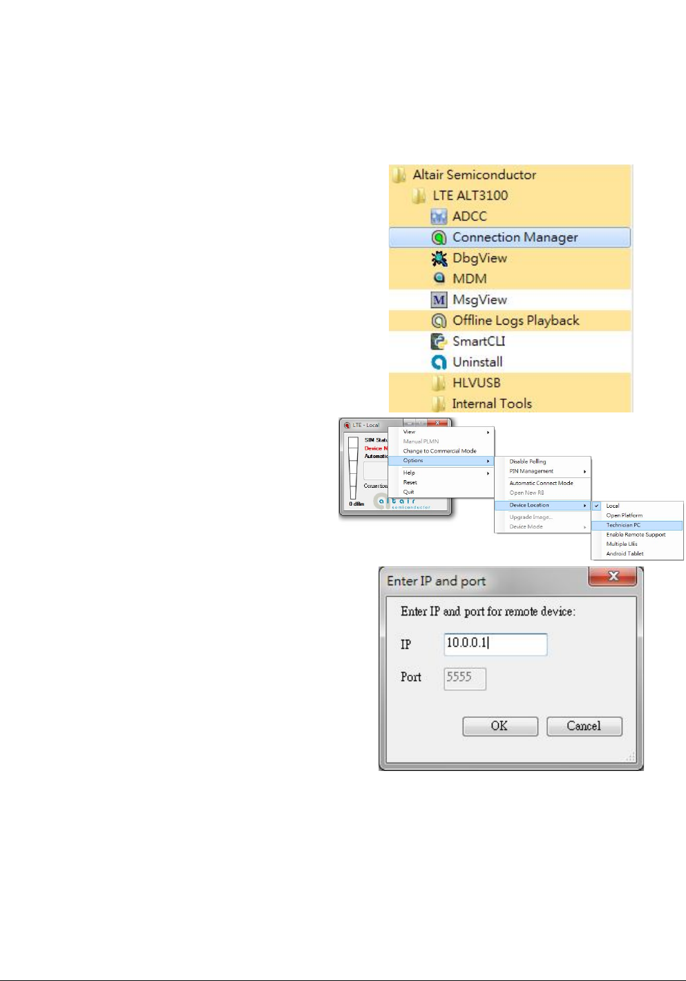
2. Please click
StartProgramsAltair SemiconductorLTE
ALT3100Connection Manager.
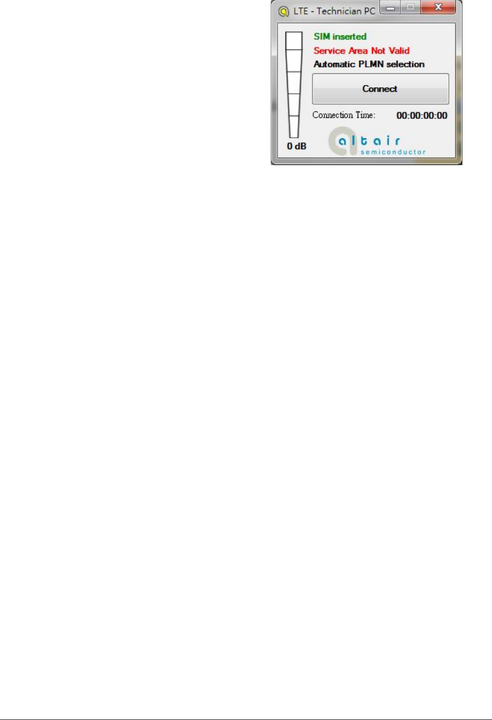
3. Please right click on top of connection manager
and select
OptionsDevice LocationTechnician PC.
4. Connection manager will pop out window for
you to enter IP and port.
5. Please enter IP address “10.0.0.1”. (see NOTE)
6. Please click “OK” button.
NOTE: If you have successfully installed Quanta
LM175 device, the embedded module will generate
DHCP server and its IP address is “10.0.0.1”.
Meanwhile, our Quanta device will get a DHCP
address “10.0.0.133” automatically.
Page
12
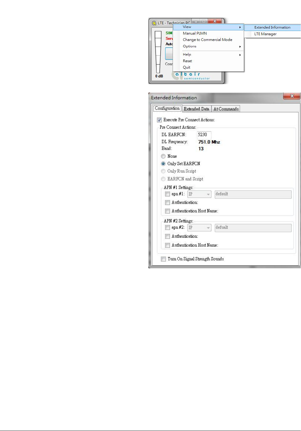
7. Please check if connection manager shows
device information correctly and the red Altair
logo turns into yellow color.
Page
13
3.1.2. Extended Information
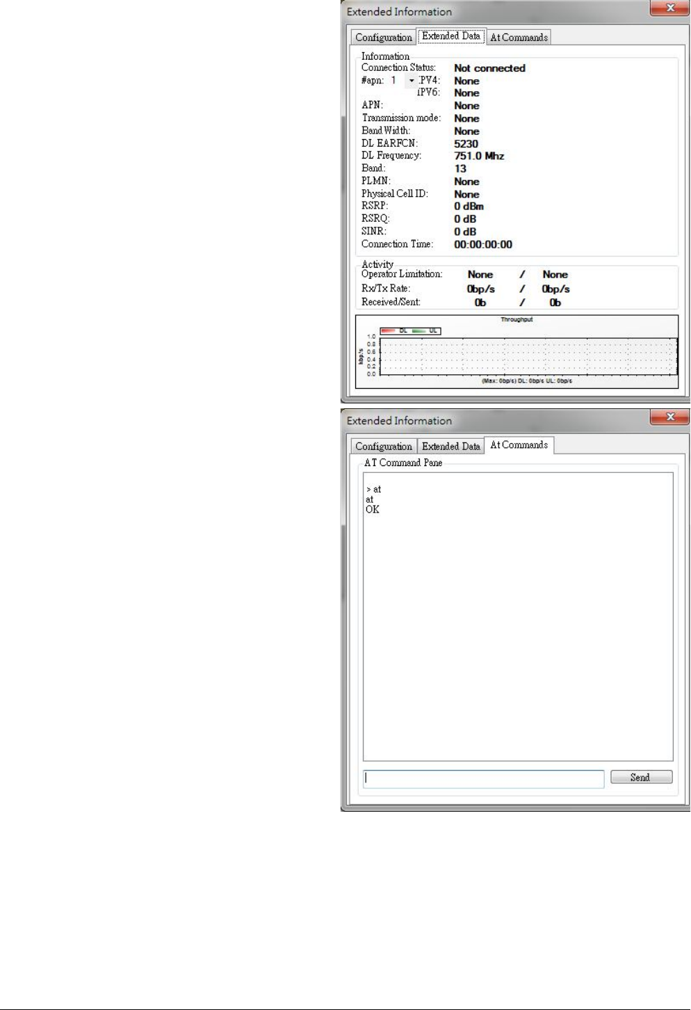
1. Please right click on top of connection manager
and select
ViewExtended Information.
2. Connection manager will pop out “Extended
Information” window.
3. It’s NOT mandatory to set up this
“Configuration” tab, connection manager will
scan all the supported frequency bands and try
to connect to the network.
Page
14
4. The “Extended Data” tab shows information of
Connection Status, APN, Transmission mode,
Bandwidth, DL EARFCN, Band, PLMN and
Physical Cell ID and so on.
5. The “At Commands” tab will allow you to send
AT Commands sets to configure supported
functional parameters or to get supported
information you want.
Page
15
3.1.3. LTE Manager
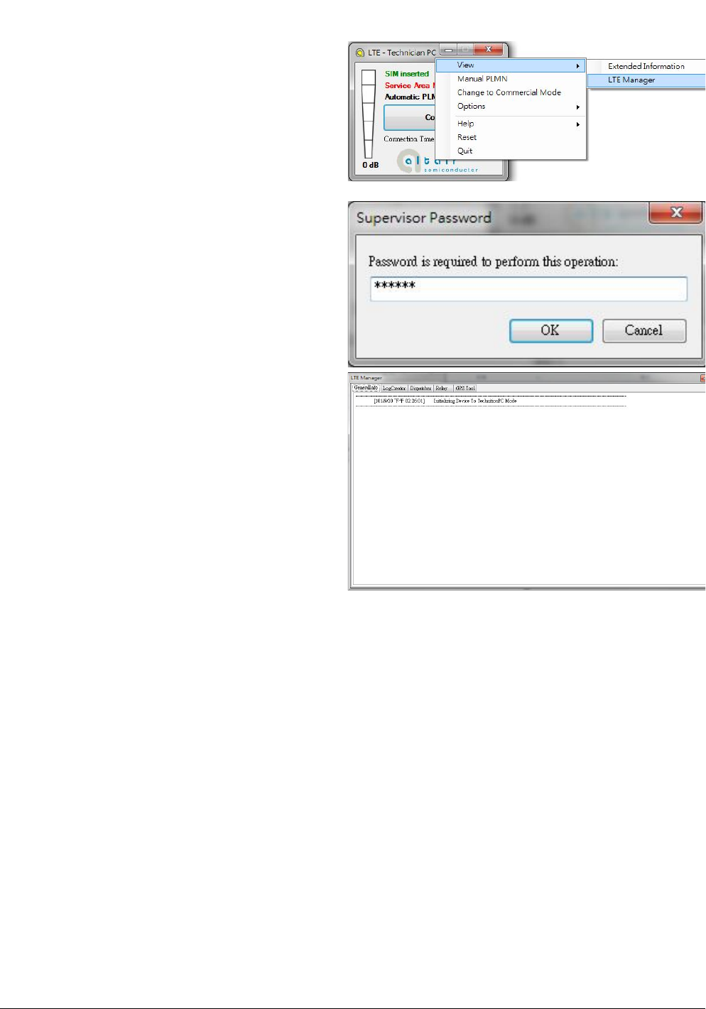
1. Please right click on top of connection manager
and select
ViewLTE Manager.
2. Connection manager will pop out a “Supervisor
Password” window.
3. Please input “123456” and click “OK” button.
4. It will pop out a “LTE Manager” window.
5. LTE Manager shows information about
GeneralInfo, LogCreator, Dispatcher, Relay, and
GPS Tool.
Page
16
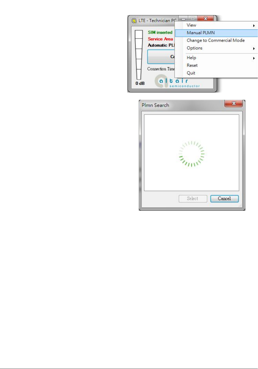
3.1.4. Manual PLMN
1. Please right click on top of connection manager
and select
Manual PLMN.
2. Connection manager will pop out a “Plmn
Search” window.
3. It’s not necessary for you to select PLMN
manually if you want to connect to network.
Page
17
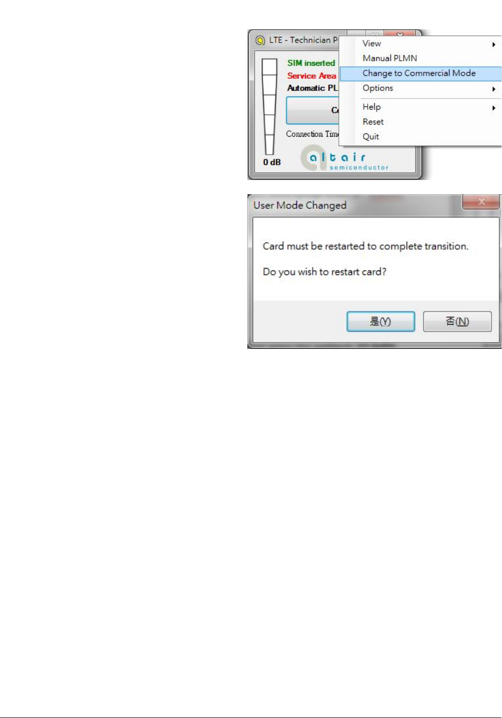
3.1.5. Change to Commercial Mode
1. Please right click on top of connection manager
and select
“Change to Commercial Mode”.
2. Connection manager will pop out a “User Mode
Changed” dialog.
3. Please click “YES (Y)” button.
4. Please wait a few seconds for device to be
ready.
Page
18
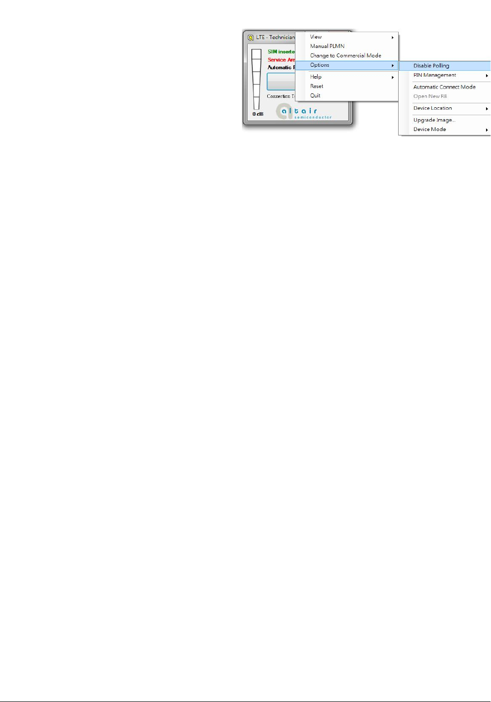
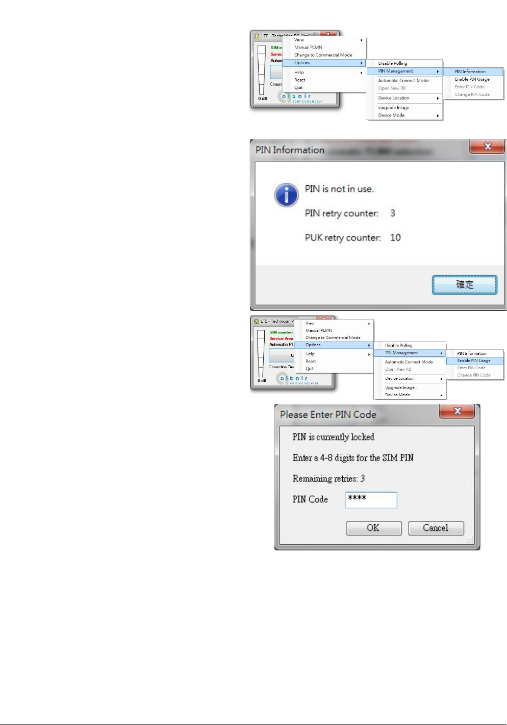
3.1.6. Disable Polling
1. Please right click on top of connection manager
and select
“OptionsDisable Polling”.
2. Connection manager will stop searching for
available network.
Page
19
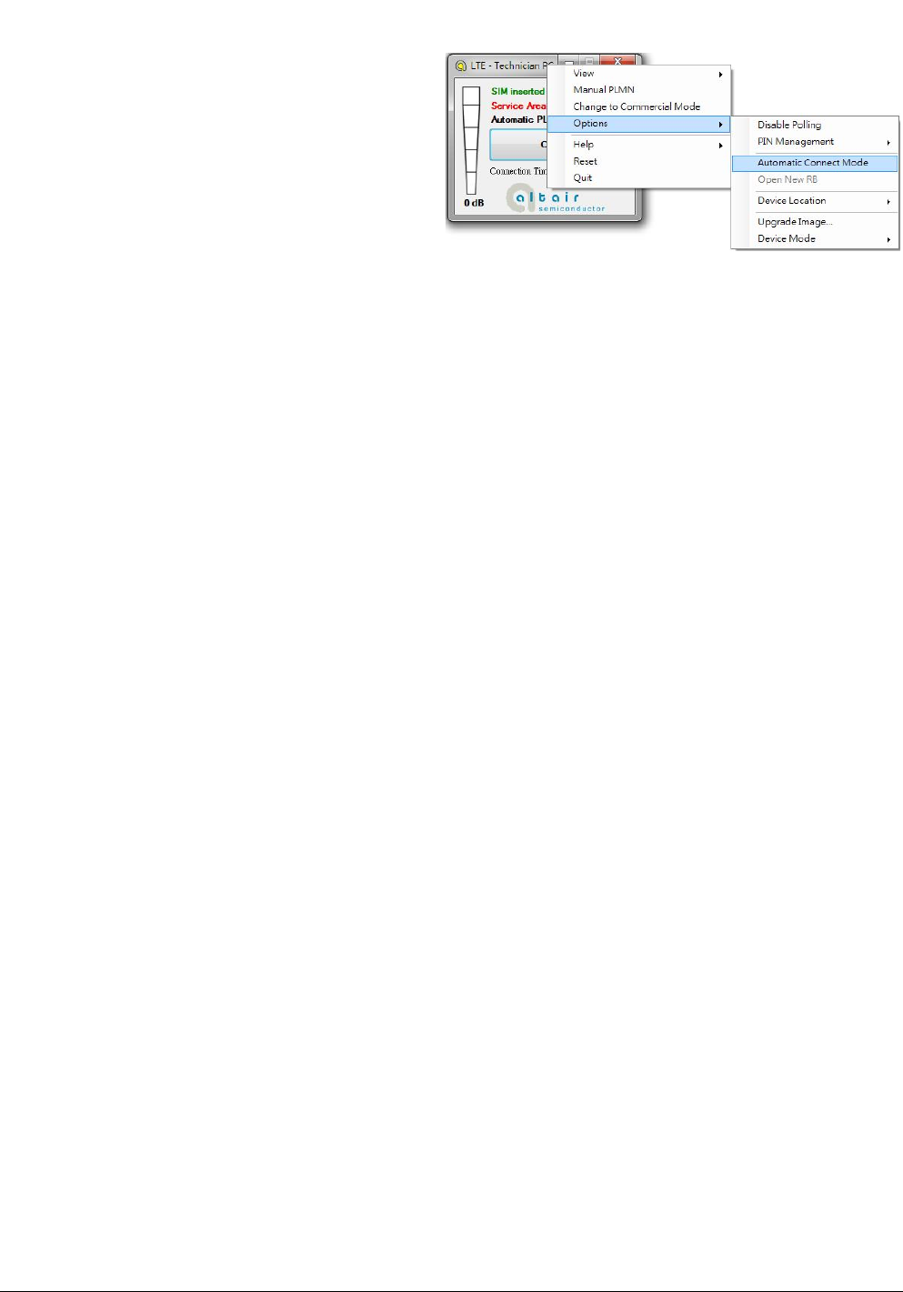
3.1.7. PIN Management
1. Please right click on top of connection manager
and select
“OptionsPIN ManagementPIN Information”
to get PIN information.
2. Connection manager will pop out “PIN
Information” window.
3. Please click “OK” button.
4. You also can enable PIN usage by right click on
top of connection manager and select
“OptionsPIN ManagementEnable PIN
Usage”.
5. Please input correct PIN code and click “OK”
button.
Page
20
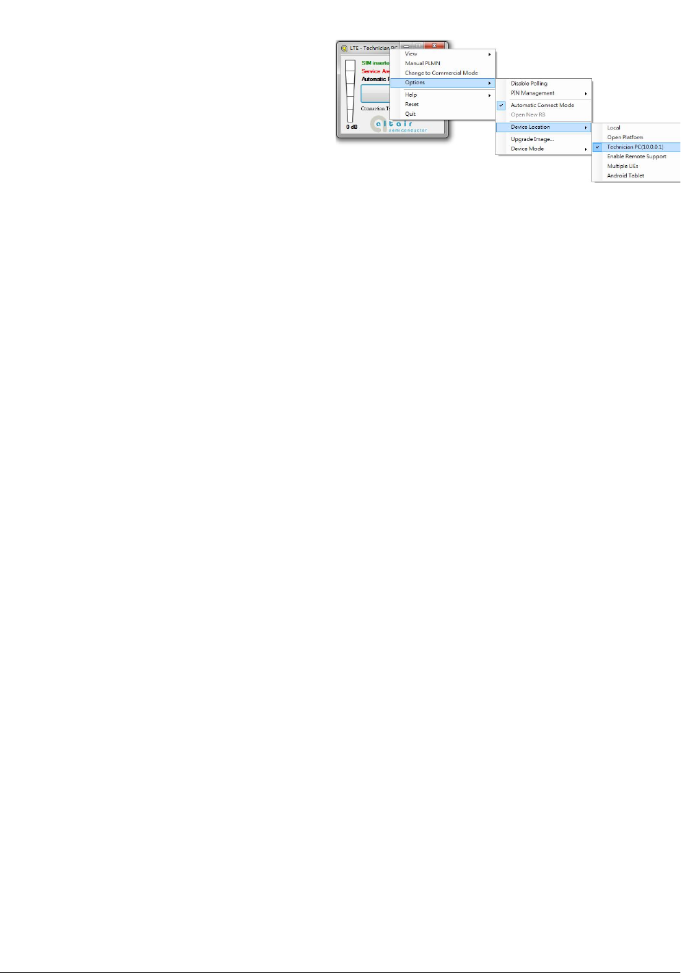
3.1.8. Automatic Connect Mode
1. Please right click on top of connection manager
and select
“OptionsAutomatic Connect Mode” to switch
connection manager from manual connect
mode to automatic connect mode.
2. Connection manager will automatically connect
to network.
Page
21
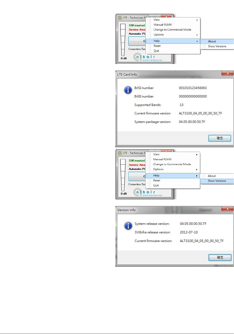
3.1.9. Device Location
1. For Quanta hostless device, please use
“Technician PC” only.
2. Please right click on top of connection manager
and select
“OptionsDevice LocationTechnician PC”.
3. Please set IP address to “10.0.0.1” and click
“OK” button.
4. Connection manager will get information from
Quanta hostless device.
Page
22
3.1.10. Help
1. Please right click on top of connection manager
and select
“HelpAbout”.
2. Connection manager will pop out a “LTE Card
Info” message box.
3. It will show information of IMSI number, IMEI
number, Supported Bands, Current firmware
version, and System package version.
4. Please click “OK” button.
5. Please right click on top of connection manager
and select
“HelpShow Versions”.
6. Connection manager will pop out a “Version
info” message box.
7. It will show information of System release
version, SWInfra release version, and Current
firmware version.
8. Please click “OK” button.
Page
23
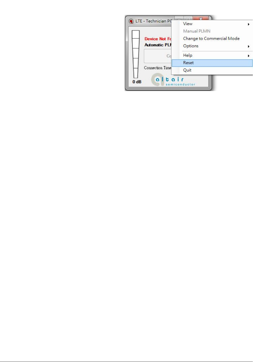
3.1.11. Reset
1. Please right click on top of connection manager
and select
“Reset”.
2. Connection manager will pop out a “” message
box.
ManualInformationtotheEndUser
TheOEMintegratorhastobeawarenottoprovideinformationtotheenduserregardinghowto
installorremovethisRFmoduleintheuser’smanualoftheendproductwhichintegratesthis
module.Theendusermanualshallincludeallrequiredregulatoryinformation/warningasshowin
thismanual.
FederalCommunicationCommissionInterferenceStatement
ThisdevicecomplieswithPart15oftheFCCRules.Operationissubjecttothefollowingtwo
conditions:(1)Thisdevicemaynotcauseharmfulinterference,and(2)thisdevicemustacceptany
interferencereceived,includinginterferencethatmaycauseundesiredoperation.
ThisequipmenthasbeentestedandfoundtocomplywiththelimitsforaClassBdigitaldevice,
pursuanttoPart15oftheFCCRules.Theselimitsaredesignedtoprovidereasonableprotection
againstharmfulinterferenceinaresidentialinstallation.Thisequipmentgenerates,usesandcan
radiateradiofrequencyenergyand,ifnotinstalledandusedinaccordancewiththeinstructions,
maycauseharmfulinterferencetoradiocommunications.However,thereisnoguaranteethat
interferencewillnotoccurinaparticularinstallation.Ifthisequipmentdoescauseharmful
interferencetoradioortelevisionreception,whichcanbedeterminedbyturningtheequipmentoff
andon,theuserisencouragedtotrytocorrecttheinterferencebyoneofthefollowingmeasures:
‐Reorientorrelocatethereceivingantenna.
‐Increasetheseparationbetweentheequipmentandreceiver.
‐Connecttheequipmentintoanoutletonacircuitdifferentfromthattowhichthereceiveris
connected.
‐Consultthedealeroranexperiencedradio/TVtechnicianforhelp.
Anychangesormodificationsnotexpresslyapprovedbythepartyresponsibleforcompliancecould
voidtheuser'sauthoritytooperatethisequipment.Thistransmittermustnotbeco‐locatedor
operatinginconjunctionwithanyotherantennaortransmitter.
RadiationExposureStatement
ThisequipmentcomplieswithFCCradiationexposurelimitssetforthforanuncontrolled
environment.Thisequipmentshouldbeinstalledandoperatedwithminimumdistance20cm
betweentheradiator&yourbody.
EndProductLabeling
Whenthemoduleisinstalledinthehostdevice,theFCCIDlabelmustbevisiblethroughawindow
onthefinaldeviceoritmustbevisiblewhenanaccesspanel,doororcoveriseasilyre‐moved.If
not,asecondlabelmustbeplacedontheoutsideofthefinaldevicethatcontainsthefollowingtext:
“ContainsFCCID:HFS‐LM175”
Thegrantee'sFCCIDcanbeusedonlywhenallFCCcompliancerequirementsaremet.
ThisdeviceisintendedonlyforOEMintegratorsunderthefollowingconditions:
(1)Theantennamustbeinstalledsuchthat20cmismaintainedbetweentheantennaandusers,
(2)Thetransmittermodulemaynotbeco‐locatedwithanyothertransmitterorantennaexceptas
describedbelow.
(3)TocomplywithFCCregulationslimitingbothmaximumRFoutputpowerandhumanexposureto
RFradiation,themaximumantennagainincludingcablelossinamobileexposureconditionmust
notexceed:
StandaloneCondition:
。 5.0dBiin1700MHzBand
。 9.0dBiin700MHzBand
AssumingcollocatedwithaWLANtransmitterwithmaximum34dBmaverageEIRPpower
。 5.0dBiin1700MHzBand
。 6.0dBiin700MHzBand
Remark:ThisassumptionisnotvalidiftheoutputpowerofthecollocatedWLANtransmitteris
higherthan34dBm.
Intheeventthattheseconditionscannotbemet(forexamplecertainlaptopconfigurationsor
co‐locationwithanothertransmitter),thentheFCCauthorizationisnolongerconsideredvalidand
theFCCIDcannotbeusedonthefinalproduct.Inthesecircumstances,theOEMintegratorwillbe
responsibleforre‐evaluatingtheendproduct(includingthetransmitter)andobtainingaseparate
FCCauthorization.Aseparateapprovalisrequiredforallotheroperatingconfigurations,including
portableconfigurationswithrespectto2.1093anddifferentantennaconfigurations.
Toensurecompliancewithallnon‐transmitterfunctions,thehostmanufacturerisresponsiblefor
evaluatinghostsystemforPart15subpartBrequirement.