Quanta Computer WF1H Notebook PC User Manual User s manual 2
Quanta Computer Inc Notebook PC User s manual 2
Contents
- 1. Manual Part 1
- 2. Manual Part 2
Manual Part 2
The modem can be operated in the following countries:
Multifrequency (MFC) dialling
Belgium, Denmark, Germany, Finland, France, Greece, Great Britain, Holland, Ireland, Iceland, Italy,
Luxembourg, Norway, Austria, Portugal, Sweden, Switzerland and Spain.
Pulse dialling:
Belgium, France, Holland and Italy.
Also in: Poland, Slovenia, South Africa and Hungary.
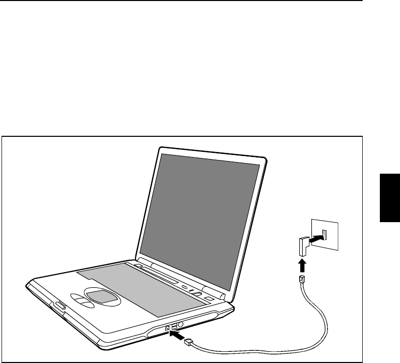
Connecting notebook modem to telephone connection
1
2
3
Ê Connect the modem cable supplied to the country-specific telephone adapter (1).
Ê Connect the modem cable to the modem port of the notebook (2).
Ê Connect the modem cable to your telephone wall socket (3).
! !
PC cards
Two PC card slots enable the notebook to operate two type II PC cards or one type III PC card
(CardBus or PCMCIA) .
!
Consult the documentation supplied by the PC card's manufacturer and follow the
instructions provided.
Never use force when inserting or removing a PC card.
Make sure that foreign objects do not fall into the PC card slot.
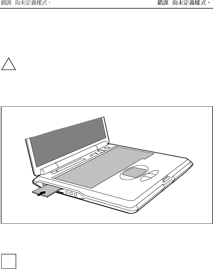
Installing a PC card
Ê Insert the PC card, contacts first, into the lower slot guide. The labelled side of the PC card must
be facing upward.
Ê Gently push the PC card into the slot until you feel it click into place.
i
Consult the documentation supplied with the PC card for information on how to install the
necessary device drivers.
For further information refer to the information files (e.g. *.TXT, *.DOC, *.WRI or *.HLP)
provided on the PC card driver diskette or the information in the operating system manual.
You can push the PC card slot eject buttons into the notebook casing. Press the eject
buttons until they snap in.
! !
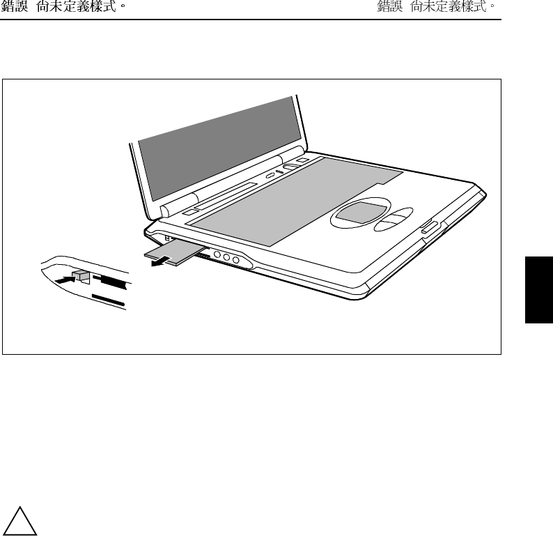
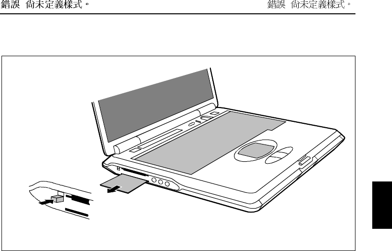
Removing a PC card
1
2
Ê Press the eject button (1). It will project further out of the notebook's case. If the eject buttons are
pushed in flush with the notebook casing, they must first be snapped out. Press the eject buttons
until they snap out.
Ê Slide the PC card out of the notebook (2).
SmartCards
The SmartCard slot enables the notebook to operate one SmartCard.
!
Consult the documentation supplied by the SmartCard's manufacturer and follow the
instructions provided.
Never use force when installing or removing a SmartCard.
Make sure that foreign objects do not fall into the SmartCard slot.
! !
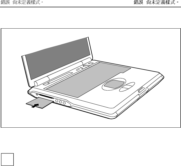
Inserting a SmartCard
Ê Insert the SmartCard, contacts first, into the lower slot guide. The labelled side of the SmartCard
must be facing upward.
Ê Gently push the SmartCard into the slot until you feel it click into place.
i
Consult the documentation supplied with the SmartCard for information on how to install the
necessary device drivers.
For further information refer to the information files (e.g. *.TXT, *.DOC, *.WRI or *.HLP)
provided on the SmartCard driver diskette or the information in the operating system manual.
You can push the SmartCard slot eject buttons into the notebook casing. Press the eject
buttons until they snap in.
! !
Pulling out a SmartCard
1
2
Ê Press the eject button (1). It will project further out of the notebook's case. If the eject buttons are
pushed in flush with the notebook casing, they must first be snapped out. Press the eject buttons
until they snap out.
Ê Slide the SmartCard out of its location (2).
! !
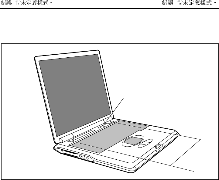
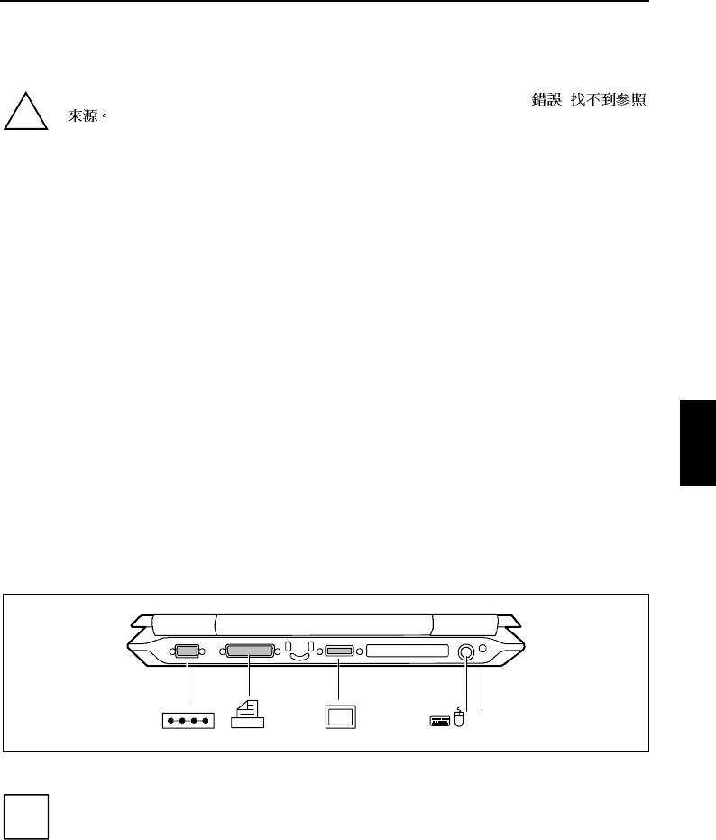
Microphone and loudspeakers
1
2
a = built-in microphone b = built-in loudspeakers
Your notebook contains a built-in microphone (a) and two loudspeakers (b).
If you attach an external microphone, the built-in microphone is disabled. The internal loudspeakers
switch off when you attach headphones or external loudspeakers to the audio jack.
! !
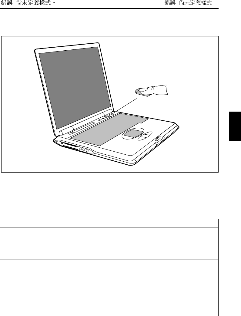
Fingerprint ???
The notebook is equipped with a fingerprint reader. Instead of entering a user password, you can also
log on to the system with a fingerprint. Before you can use the fingerprint reader, you must install the
driver provided on the CD.
Bluetooth Keyboard Product Specification
Product Bluetooth Keyboard
Radio Specification [1] Frequency range: 2.402 – 2.480 GHZ
[2] RF output Power: Class 3
[3] Receiver Sensitivity: -70dBm at 0.1% BER
[4] Cover distance: 3 meter (max)
Electrical Characteristics [1] Power supply: Transmitter board at keyboard site will be powered by
Li-ion 1100 mAh battery; receiver board at PC site is powered by
5Volt DC through USB connector
[2] Power consumption: 80 mA max. (Transmitter board)
[3] Visual indicator: LED indicators: Caps Lock, Num Lock, Scroll Lock,
Battery status, Bluetooth connection status
[4] Auto reconnecting:

! !
Automatically re-connect keyboard with notebook PC
[5] Batter life: 24 hour (20,000 times key press)
Intended use/purpose of
the equipment Notebook with detachable K/B which can wireless communicate Notebook
Type of modulation GFSK
Channel spacing 1Mhz
Designation of emission ETSI 300 328
ETSI 300 826
Transmit RF power or
power range -6 dBm ~ 0dBm
Duty cycle 625us
Channel access protocol TDMA
Duplex direction Duplex
Antenna Type Micro Strip ANT
Peak Gain > 3dBi, <-5dBi
Vswr<= 2
Return loss <= -10 dBm
Reference standard or
other specification Bluetooth spec. V1.1
! !
Property and data protection
Your notebook enables you to protect your system and personal data in a number of ways against
unauthorised access. By combining these options, you can achieve maximum protection for your
system.
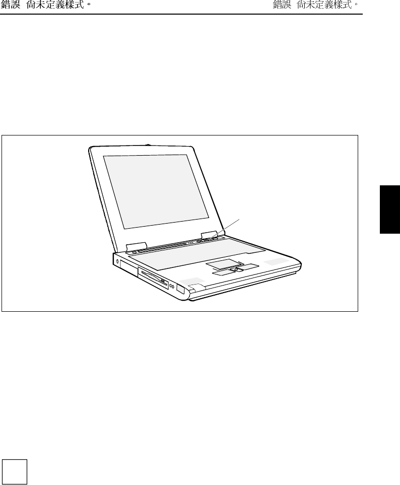
Security panel
a
a = Security panel
The security panel enables you to protect your notebook from unauthorised use with a hardware
password. When a Security Panel password is activated, the notebook will not start without the correct
insertion of a password. The password is entered before the BIOS is read out and the hardware
activated.
The password is requested from all suspend and resume modes. As a result, a security level is also
provided with the energy-saving mode activated.
The Security Lock function can be used when the notebook is started from the Resume mode, when
switched off and from the Save-to-Disk mode.
Password protection of Save-to-RAM Mode is also supported. This function can be deactivated in the
BIOS Setup. In the Security Panel on Resume menu the default value is set to Enable at the factory.
It is possible to assign a supervisor password and a user password.
i
If you have forgotten your user password, you can use the supervisor password to reset the
user password, and you can then enter a new user password.
If the security panel is active and you have forgotten both passwords, please contact your
our Hotline/Help Desk.
The supervisor password must be set so that the notebook can be unlocked again, and so that a new
user password can be assigned when the existing one has been forgotten.
! !
No passwords are assigned when the notebook is delivered. The passwords can be assigned with the
FJSECS.EXE (supervisor password) and FJSECU.EXE (user password) programmes. The supervisor
password and the user password can be assigned with up to 4 key entries. Multiple keys (1+2) can be
used together as one key entry.
i
The supervisor password has to be set before the user password can be assigned.
Assigning a supervisor password
The setup programme can be found under Start - AddOn Software.
Ê Enter the programme name FJSECS.EXE under Start - Run.
Ê Click on OK.
Ê Follow the instructions of the programme.
Assigning a user password
The setup programme can be found under Start - AddOn Software.
Ê Enter the programme name FJSECU.EXE under Start - Run.
Ê Click on OK.
Ê Follow the instructions of the programme.
Examples of possible password combinations
"1" + Enter
"1" + "2" + Enter
"1" + "2" + "3" + Enter
"1" + "2" + "3" + "4" + Enter
("1"+"2") + ("1" + "2" + "3" ) + ("1" + "2" + "3" + "4" ) + "1" + "2" + Enter
i
("1" + "2") means that the key "1" and "2" must be pressed simultaneously.
"Enter" refers to the Enter key of the Security Panel under the LCD screen.
Password error alarm
If a password is entered incorrectly three times, a one-minute alarm is triggered. If the correct
password is entered during the alarm, the notebook starts up normally.
After one minute the notebook stops the alarm. The user must press the Suspend/Resume key to start
or enter the Resume mode.
After pressing the Suspend/Resume button, the notebook is locked again; the user must now enter the
correct user password again. If the entry is correct, the notebook will start.

! !
Security functions under Windows
Under Windows you can activate a screen saver and protect it with a password. Only those users who
know the password can deactivate the screen saver and access any open files.
BIOS Setup security functions
The Security menu in BIOS Setup offers you various options for protecting your personal data against
unauthorised access. By combining these options, you can achieve maximum protection for your
system.
Preventing unauthorised BIOS Setup entry
You can activate this protection by setting a supervisor or a user password in the Security menu
(Set Supervisor Password/Set User Password).
Preventing unauthorised system access
You can activate this protection by setting a password in the Security menu. In addition, you must
select the entry Enabled in the Password on boot field.
Preventing unauthorised access to the hard disk drives
You activate this protection when you set a hard disk passwords in the Hard Disk Security submenu of
the Security menu. To do this, set the entry HDD password to Enabled and assign your password.
If set, the hard disk passwords are checked at each system startup, regardless of whether
Password On Boot is set to Enabled or Disabled.
Preventing unauthorised access to floppy disk drive
To activate this protection, select the value Supervisor for the Diskette access field in the Security menu.
Setting passwords
A user password can only be set if a supervisor password has been assigned. The supervisor or user
password prevents unauthorised callup of BIOS Setup. Only those who know one of the two passwords
can call BIOS Setup.
With the supervisor password you have access to all functions of the BIOS Setup. With the user
password you only have access to part of the functions of the BIOS Setup.
The user password also prevents unauthorised access to your notebook. With the user password you
can prevent booting of the operating system. Only those who know the user password can access the
system.
i
Passwords can be up to eight characters long. All alphanumerical characters can be used;
no differentiation is made between upper-case and lower-case.
Passwords are not displayed as they are entered.
If you have forgotten a password, contact your system administrator or contact our customer
service centre.
! !
To set or change a password, proceed as follows:
Ê Call BIOS Setup and select the Security menu (see chapter "Settings in BIOS Setup"). You must
additionally change into the Hard Disk Security submenu for the hard disk passwords.
Ê Mark the Set Supervisor Password or Set User Password field and press the Enter key.
You are asked to enter a password:
Enter new Password:
Ê Enter the password and press the Enter key.
You are asked to confirm the password:
Re-enter new Password:
Ê Enter the password again and press the Enter key.
The new password is saved.
Notice: Changes have been saved [continue]
Ê To prevent booting of the operating system, mark the Password on boot field and select the value
Enabled.
If you do not want to make any other settings, you can exit BIOS Setup.
Ê Select the option Exit Saving Changes in the Exit menu.
The notebook is rebooted and the new password is effective.
Cancelling passwords
Supervisor / User password
i
If you cancel the supervisor password, you automatically deactivate the user password.
To cancel a password (without setting a new password):
Ê Call BIOS Setup and select the Security menu (see chapter "Settings in BIOS Setup").
Ê Mark the Set Supervisor Password or Set User Password field and press the Enter key.
You are asked to enter a password:
Enter new Password:
Ê Press the Enter key twice.
Ê Select the option Exit Saving Changes in the Exit menu.
The notebook is rebooted and the password is cancelled.
Hard disk password
To cancel a password (without setting a new password):
Ê Call BIOS Setup and select the Security menu (see chapter "Settings in BIOS Setup").
Ê Change into the submenu Hard Disk Security.
Ê Set the entry HDD password to Disabled in the Hard Disk Security submenu.
You are asked to enter a password:
Enter new Password:
Ê Press the Enter key twice.
! !
Ê Select the option Exit Saving Changes in the Exit menu.
The notebook is rebooted and the password is cancelled.
Access protection with SICRYPT PC Lock
With SICRYPT PC Lock you can protect your system from unauthorised booting. Then a system can
only be booted when the user inserts a valid SmartCard in the SmartCard reader and enters his/her
personal code number (PIN). To use PC Lock you require the following components:
• External or internal SmartCard reader
• PC Lock installed (see manual "BIOS Setup")
• SICRYPT SmartCard
i
There are two different SmartCards - the Admin SmartCard and the User SmartCard. These
differ in their memory capacity. In addition to the access permissions, you can also save
other safety options on the Admin SmartCard (e.g. fingerprints with the Smarty 2 software).
PC Lock controls access to your PC. When a SmartCard is initialised, permissions are assigned for
system access (system, setup, system+setup, admin). You can configure several SmartCards for one
system and initialise them with different permissions.
In this way users can be divided into user groups. Users of a user group use SmartCards with the
same permissions.
Additional instructions for PC Lock
i
Do not use PC Lock on systems controlled by tele-maintenance. If a SmartCard is
inserted and the User PIN must be entered, an automatic system boot is blocked. For
example, this is the case with "Wake On LAN", or when software is to be installed via
the network that requires a system reboot.
After you have initialised the first SmartCard, the entry PC-Lock can no longer be
deactivated (Disabled) in the BIOS Setup.
If you also want to use other security software in addition to PC Lock (e.g. SmartGuard
Pro), please read the documentation on your security software beforehand.
! !
PC Lock permissions
You can initialise a SmartCard with one of the following permissions:
System The system starts following entry of the user PIN. You can change the user PIN.
Setup You can open and change the BIOS Setup and change the user PIN.
System+Setup The system starts following entry of the user PIN. You can open and change the
BIOS Setup and change the user PIN.
Admin The system starts following entry of the user PIN. You can change the user PIN
an the administrator PIN, unlock locked SmartCards, open and change the BIOS
Setup and generate additional SmartCards for this system.
For instructions on how to install and operate SICRYPT PC Lock, and how to initialise SmartCards,
see the "BIOS Setup" manual.
Operating the SmartCard reader
• Operating the internal SmartCard reader
You can switch on the PC by inserting your SmartCard. If the SmartCard reader has been released,
the SmartCard reader indicator on the front of the PC flashes green.
• Operating the external SmartCard reader
After the PC is switched on, you will be prompted to insert your SICRYPT SmartCard.
Kensington Lock
a
a = Kensington Lock
! !
You can protect your notebook from theft with the Kensington Lock device (a) and a Kensington
MicroSaver.
Connecting external devices
!Under all circumstances, please observe the safety notes provided in the " !
" chapter.
Read the documentation on the external device before connecting it.
Do not connect or disconnect cables during a thunderstorm.
Do not pull on the cable when disconnecting a cable. Always take hold of the actual plug.
Adhere to the order described in the following when you connect external devices to the
notebook or separate them from the notebook:
Connecting devices to notebook
1) Turn off all power and equipment switches.
2) Pull all power plugs out of grounded mains outlets.
3) Connect all the cables to the notebook and the external devices.
4) Plug all data communication cables into the utility sockets.
5) Plug all power cables into the mains supply.
Disconnecting devices from notebook
1) Turn off all power and equipment switches.
2) Pull all power plugs out of grounded mains outlets.
3) Unplug all data communication cables from the utility sockets.
4) Disconnect all the cables from the notebook and the external devices.
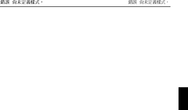
Ports
DC In
Connections on the rear
i
The connection without a symbol (second connection from the right) is the docking
connection. It makes the connection between the devices when you dock the notebook to a
docking device.
! !
Line In
Connections on the left side
LAN
IR
Connections on the right side
! !
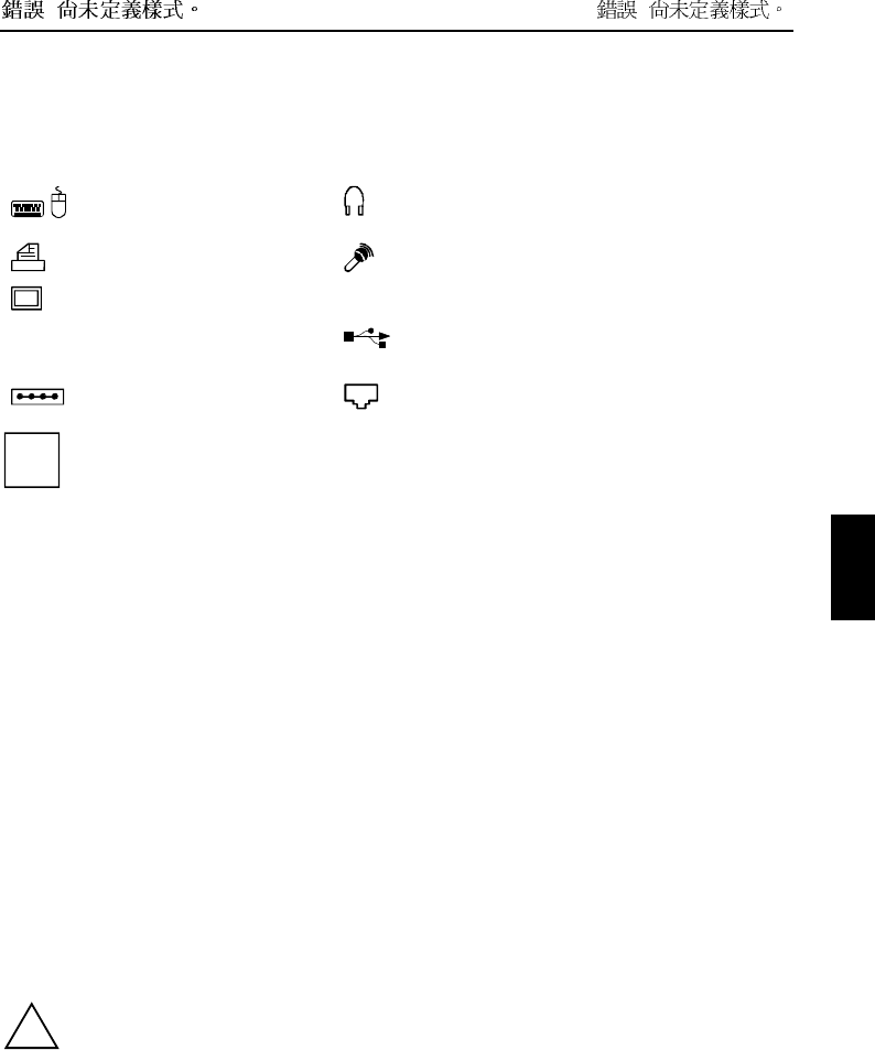
The ports are marked with the following symbols (or with similar symbols):
LAN LAN-port
(Local Area Network, for
Network connection)
DC In Port for power adapter
PS/2 port (for keyboard or
mouse)
Headphones port
Parallel port Microphone connector
Monitor port IR Infrared port
TV TV out socket
(video output)
USB port
Serial port Modem connector
i
Some of the external devices require special drivers (see the operating system and external
device documentation).
Connecting an external monitor
An external monitor can be connected to the notebook. The screen controller in your notebook
supports extended SXGA resolutions of up to 1280x1024/60 Hz and 16 bit colour depth.
• Using the [Fn] + [F10] key combination you can switch back and forth between the external
monitor and the LCD screen.
• If your notebook is equipped with a TFT monitor, you can display the same picture on the external
monitor and the LCD screen simultaneously.
Ê Switch off the notebook and the external monitor.
Ê Connect the external monitor to the monitor port on your notebook.
Ê First switch on the monitor and then the notebook.
Setting the refresh rate for your external monitor
The refresh rate must be correctly set so that the image does not flicker.
Ê To change the refresh rate or resolution select the monitor type in the menu Start - Settings -
Control Panel - Display - Settings - Advanced - Monitor.
Ê Now select the Adapter tab.
Ê Adjust the refresh rate and then click Apply.
!If the refresh rate set is too high, the monitor may be damaged. Please see the
documentation included with your monitor for the maximum possible refresh rate.

! !
Connecting an external keyboard
You do not need to switch off your notebook.
Ê Simply connect the external keyboard to the PS/2 port on your notebook.
Connecting an external PS/2 mouse
You do not need to switch off your notebook.
Ê Simply connect the mouse to the PS/2 port on your notebook.
Connecting a serial mouse
Ê Switch off the notebook.
Ê Connect the mouse to the parallel port on your notebook.
Ê Switch the notebook on.
Ê Run the mouse service programme under Start - Settings - Control Panel and select the General
tab.
Ê Select the correct mouse type.
Ê Restart the notebook.
Using the parallel port
Ê Switch off the notebook.
Ê Connect the data cable of the printer to the parallel port on the notebook.
Ê Plug the power cable of the printer into the mains outlet.
Ê First switch on the printer, then the notebook.
Using the serial port
Ê Switch off the notebook.
Ê Connect the data cable of the printer to the parallel port on the notebook.
Ê Plug the power cable of the printer into the mains outlet.
Ê First switch on the printer, then the notebook.
! !
Establishing an infrared connection
Using the infrared software for Windows, you can communicate with another PC or printer equipped
with an infrared interface.
i
Before you can establish an infrared connection, you must have activated the infrared
software. Additional information on the infrared interface is contained in the Windows help in
the Start menu under the topic "Infrared".
Configuring the infrared connection
By default, the mode for the infrared port is set to FIR in the BIOS Setup ("Fast IrDA Mode"). If you
want to communicate with a system on which Windows ME is not running, you can change the setting
to IrDA. Please note that IrDA is the slower mode and is generally used on older computers.
Connecting USB devices
On the USB ports you can connect external devices that also have a USB port (e.g. a printer, a
scanner or a modem).
i
USB devices are hot-pluggable. This allows cables from USB devices to be connected and
disconnected with the system switched on.
Additional information can be found in the documentation for the USB devices.
Ê Connect the data cable to the external device.
Ê Connect the data cable to a USB port .
i
Device drivers
The devices you connect to the USB ports usually require no driver of their own, as the
required software is already included in the operating system. However, if the USB device
requires its own software, please install it from the data carrier provided with the USB
device.
Operating notebook with docking device
Docking devices turn notebooks into convenient standard workstations in a flash. Only the Port
Replicator II-L can be used as a docking device for this notebook.
For additional information on the Port Replicator II-L, also see the documentation on the docking
devices.
i
You should install your notebook's software (operating system, device drivers) before
docking your notebook the first time.
! !
Connections for external devices on the Port Replicator II-L
The ports for external devices are on the rear of the port replicator II-L. The standard ports are
indicated by symbols.
i
The LAN connection on the Port Replicator II-L only functions when your notebook is
equipped with an internal LAN or modem/LAN module. Otherwise this connection is
inoperative.
i
The serial, parallel and audio ports can be configured in the BIOS Setup of the notebook.
Some of the devices that you connect require special drivers (e.g. a printer driver for the
printer). For information on which driver you need to install and where, please refer to the
documentation for the device concerned.
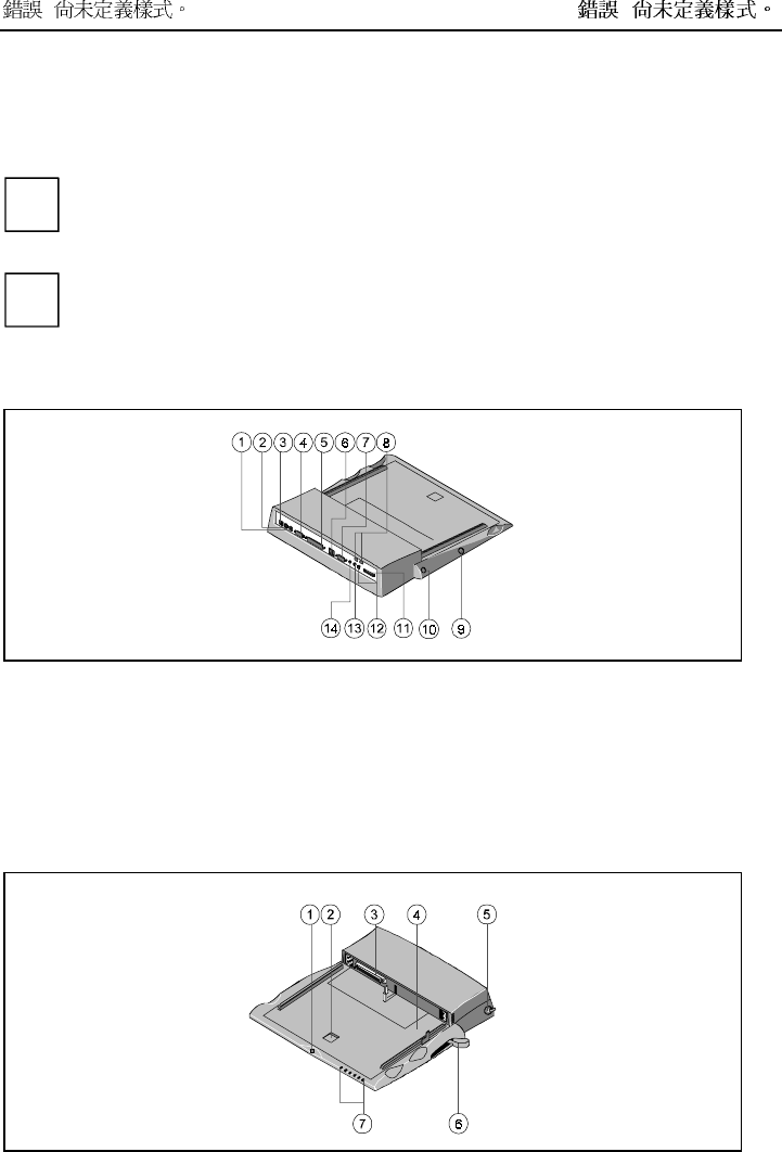
The following illustration shows the positions of the connections on the II-L port replicator.
1 = Keyboard port
2 = PS/2 mouse port
3 = DC jack (DC IN)
4 = Serial port
5 = Parallel port
6 = Two USB ports
7 = Monitor port
8 = LAN connector
9 = ON/OFF switch (Standby button)
10 = Reset button
11 = Connection for floppy disk drive*)
12 = Audio input (Line in)
13 = Microphone connector
14 = Headphones port
*) has no function on this LIFEBOOK C-Serie
! !
1 = Eject button*)
2 = Platform release lever
3 = Docking port
4 = Device-specific platform (Tray F)
5 = Kensington Lock
6 = Manual eject lever
7 = Indicators*)
*) has no function on this LIFEBOOK C-Serie
Indicators on the II-L port replicator
i
The indicators and the eject button on the front of the Port Replicator II-L are covered by the
device platform of this LIFEBOOK C-Serie, and are therefore inoperative.
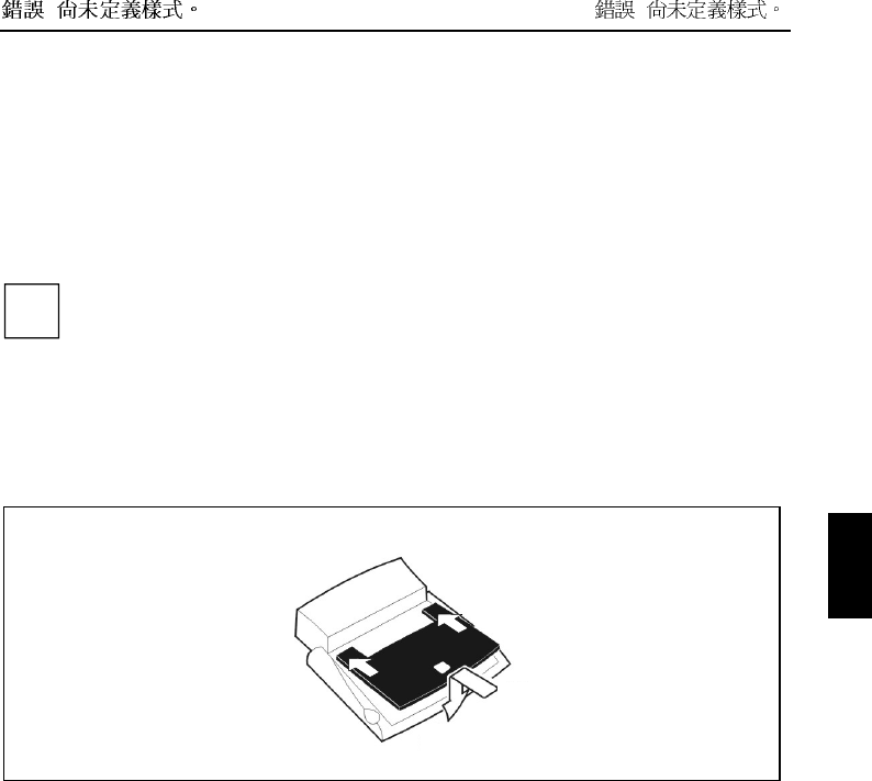
Mounting the Tray
A Tray assumes the mechanical adaptation of the notebook to the docking device. You must mount the
Tray on the docking device before you can dock the notebook.
For this LIFEBOOK C-Serie you require the device platform F.
2
1
1
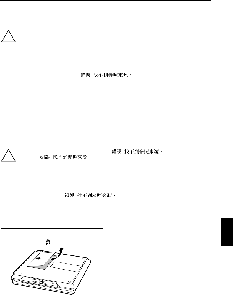
Ê Hold the Tray at an angle over the docking device and push the Tray straight into the notches in
the docking device (1).
Ê Press down the front corners of the Tray (2) until they engage.
! !
Removing the Tray
Ê Push the release (1) in the direction of the arrow until the Tray is released on both sides.
Ê Remove the Tray (2).
Docking the notebook
Docking notebook while running
If an operating system is installed on your notebook that supports "Plug & Play" and "hot docking" (e.g.
Windows 98), you need not switch off the notebook for docking.
The notebook may also be in an energy-saving mode.
!The power adapter cable may not be connected to the DC socket (DC IN) of the notebook
when you dock the notebook. The notebook must be in the battery mode.
Ê Put your docking device into operation (see documentation for the docking devices).
Ê Mount the suitable Tray on the docking device.
Ê Disconnect all cables connected to notebook.
Ê Make sure that the PC card eject buttons of the notebook are pressed in.
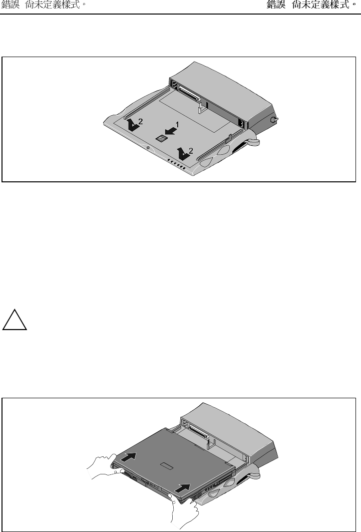
! !
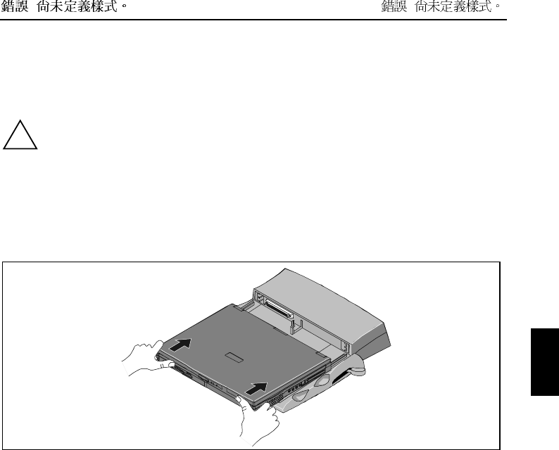
Ê Place your notebook on the docking device and push it evenly in the direction of the arrows until
you feel it engage.
Docking a notebook while switched off
!The power adapter cable may not be connected to the DC socket (DC IN) of the notebook
when you dock the notebook. The notebook must be in the battery mode.
Ê Put your docking device into operation (see documentation for the docking devices).
Ê Mount the suitable Tray on the docking device.
Ê Switch off the notebook.
Ê Disconnect all cables connected to notebook.
Ê Make sure that the PC card eject buttons of the notebook are pressed in.
Ê Place your notebook on the docking device and push it evenly in the direction of the arrows until
you feel it engage.
! !
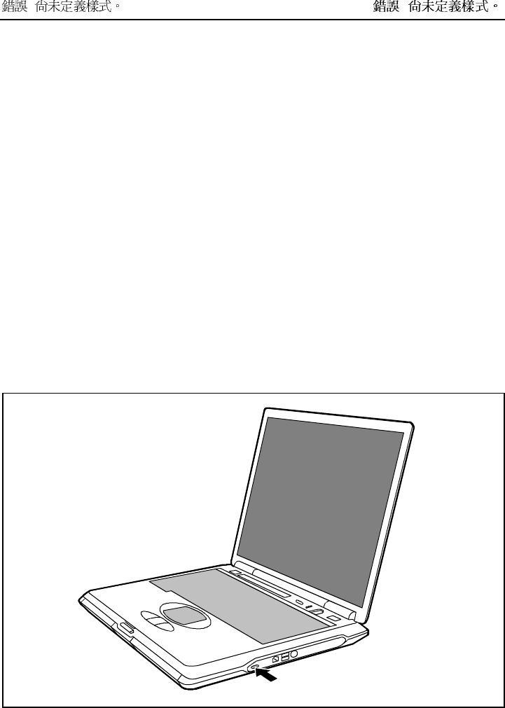
Switching on docked notebook
Ê Press the Suspend/Resume button of the notebook.
or
Ê Press the Suspend/Resume button on the left-hand side of the docking device.
Undocking the notebook
Undocking notebook while running
If an operating system is installed on your notebook that supports "Plug & Play" and "hot docking" (e.g.
Windows 98), you need not switch off the notebook for undocking.
The notebook may also be in an energy-saving mode.
Windows 98/2000
You must prepare the notebook for undocking.
Ê To do this, select Eject PC in the Start menu.
Windows NT
i
To remove your notebook under Windows NT while running the software Portable Suit for
NT4.0 (Notedock, Cardexecutive, PowerProfiler) must be installed.
Ê Click on Undock in the Notedock window (additional software Portable Suit for NT4.0).
Undocking notebook when switched off
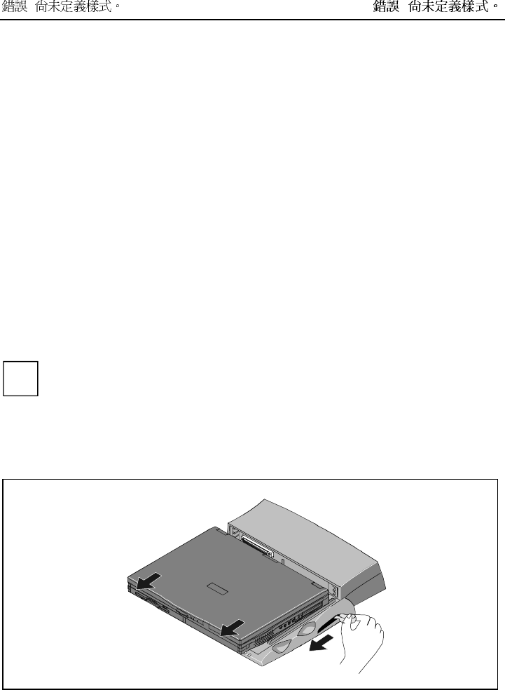
1
2
2
Ê Move the lever in the direction of the arrow (1).
Ê Remove the notebook toward the front (2).

Settings in BIOS Setup
In BIOS Setup you can set the system functions and the hardware configuration of the notebook. The
settings can only be changed via the keyboard.
When it is delivered, the notebook is set to factory default settings. You can change these settings in
BIOS Setup. Any changes you make take effect as soon as you save and quit the BIOS Setup.
The BIOS Setup programme contains the following menus:
Main: for system settings as time, date, hard disk and monitor selection
Advanced: for system settings such as ports and keyboard
Security: for password settings and safety functions
Power: for setting the energy saving functions
Boot: for configuring the boot sequence
Info: for displaying the system configuration (e.g. processor and memory configuration)
Exit: to exit the BIOS Setup
Start BIOS Setup
Ê Restart the notebook (switching ON/OFF or warm boot).
The following display briefly appears on the screen during start-up:
<ESC> Diagnostic screen <F12> Boot Menu <F2> BIOS Setup
Ê When this message appears, press the key [F2].
i
If a password has been assigned:
Ê Enter the password and press the Enter key.
If you have forgotten the password, contact your system administrator or contact our
Hotline/Help Desk.
Operating BIOS Setup
i
Press the [F1] key to display help on the operation of BIOS Setup.
The description of the individual settings is shown in the right-hand window of the BIOS
Setup.
Using the [F9] function key, you can load the default settings for the BIOS Setup menu you
are currently in.
Ê Use the cursor key å or ç to select the menu you wish to access to make changes.
Ê Press the Enter key.
The menu is displayed on the screen.
Ê Use the cursor key æ or è to select the field you wish to change.
Ê Press the space bar to confirm your selection.
Ê Press the [ESC] key to exit the selected menu.
Ê Make a note of the changes you have made (here in this manual, for example).

!
Exiting BIOS Setup
To exit BIOS Setup, select the Exit menu from the menu bar. You can then decide which settings you
want to save. The Exit menu offers the following options.
You must mark the required option and activate it with the Enter key.
Exit Saving Changes
Select Exit Saving Changes and Yes to save the current settings and exit the BIOS Setup. The device is
rebooted and the new settings come into effect.
Exit Discard Changes
Select Exit Discard Changes and Yes to discard the changes you have made. The settings which were
in force when BIOS Setup was called remain effective. BIOS Setup is terminated and the device is
rebooted.
Load Setup Default
To revert all the menus of BIOS Setup to the default entries, select Load Setup Default and Yes.
Discard Changes
To load the values of all the menus of BIOS Setup that were in effect when BIOS Setup was called,
select Discard Changes and Yes. If you want to exit BIOS Setup with these settings, select Exit Saving
Changes and Yes.
Save Changes
To save settings without exiting BIOS Setup, select Save Changes and Yes.

Troubleshooting and tips
!
Take note of the hints in the chapter "Connecting external devices", when you connect or
disconnect cables.
If a fault occurs in your notebook, try to eliminate it with the measures described in this chapter. If you
fail to correct the problem, proceed as follows:
Ê Make a note of the steps and the circumstances that led to the fault. Also make a note of any
error messages displayed.
Ê Switch off the notebook.
Ê Contact your sales outlet or our Hotline/Help Desk.
Installing new software
When installing programmes or drivers, important files may be overwritten and modified. To be able to
access the original data in the case of any problems following installation, you should backup your hard
disk prior to installation.
Saving and restoring system files
With "Microsoft Backup" you can create backup copies of your system files and restore the files. We
recommend that you create a backup copy of all important files after switching on your notebook for the
first time.
Ê Click on Start and select Accessories and System Programs.
Ê Click on Backup.
Ê Depending on whether you want to create a backup copy or restore the files, select either the
Backup or the Restore tab.
Ê Follow the instructions on the screen.
Restoring the hard disk contents under Windows
Using the Windows Recovery CD and the Drivers & Utilities CD, you can restore the operating system
of your notebook.
During restoring the operating manual the contents of your hard disk will be overwritten. After this,
operating system, drivers and software utilities will be reinstalled. For this reason you should try to
save important data to a backup medium before you restore the hard disk contents.
Ê Insert the "Start-Disk for Windows" into the floppy disk drive and switch the notebook on.
Ê Follow the instructions on the screen.
i
Detailed PC knowledge is required for manual partitioning.
Ê Insert the Windows Recovery CD into the optical drive.
!
Ê Start the Setup programme on the CD.
You must then reinstall all the drivers. Use the "Drivers & Utilities" CD.
The notebook's date or time is incorrect
Ê Double-click on the clock in the task bar and adjust the time.
or
Ê Set the time and/or date in the BIOS Setup menu Main.
i
If the date and time are repeatedly incorrect when you switch on the notebook, the buffer
battery that supplies the internal clock is dead.
Connect the notebook via its power adapter to a grounded mains outlet or install a fresh
battery. The buffer battery will take approximately two days to complete its recharge. Should
the problem persist, please contact our Hotline/Help Desk.
Battery indicator does not illuminate
Battery is not installed or is defective
If the battery status indicator does not light up, either no battery is installed or there is no contact
between the notebook and the battery.
Ê Check whether the battery is installed correctly in its compartment.
It may be necessary to replace the battery with a new one. When you dispose of used batteries, please
observe the safety instructions in the chapter " ! ".
The LCD screen of the notebook remains blank
Monitor is switched off
Ê Press a key or enter the password
External monitor or television set connected
Ê Set the setting Display Settings to LCD BIOS-Setup in the menu Advanced - Video Features.
The notebook's LCD screen is difficult to read
Reflection
Ê Turn the notebook or alter the tilt of the LCD screen.

!
The external monitor stays blank
If your screen remains blank this may be due to the following:
Monitor is switched off
Ê Switch the external monitor on.
Power saving has been activated (screen is blank)
Ê Press any key to continue.
Brightness is set too dark
Ê Adjust the brightness of the monitor.
Screen output is set to the notebook’s LCD screen
Ê Press the key combination [Fn] + [F10] (selecting internal/external display).
The external monitor's power cable or data cable is not connected properly
Ê Switch off the external monitor and the notebook.
Ê Check whether the power cable is plugged properly into the power adapter and into the mains
outlet.
Ê Check whether the data cable is properly connected to the notebook and the external monitor (if it
is plugged in with a connector).
Ê Switch on the external monitor and the notebook.
The external monitor is blank or the image is unstable
Two causes are possible: An incorrect type has been selected for the external monitor or the wrong
screen resolution has been set for the application program.
Ê Terminate the application programme with [Alt] + [F4].
If the fault continues to occur after ending the programme, switch over to the notebook's internal LCD
screen with [Fn] + [F10]. Change the following setting:
Ê Select Start - Settings- Control Panel - Display - Settings and then the screen resolution you require
in the Resolution field.
or
Ê Select the correct monitor under Start - Settings- Control Panel - Display - Settings - Advanced
Properties - Monitor - Modify.

!
The notebook cannot be started
If the notebook does not start after switch on, this may be due to one of the following:
The battery is not installed correctly
Ê Switch off the notebook.
Ê Check whether the battery is installed correctly in its compartment.
Ê Switch the notebook on.
The battery is dead
Ê Charge the battery.
Or
Ê Install a charged battery.
Or
Ê Connect the power adapter to the notebook.
The power adapter is not connected correctly
Ê Switch off the notebook.
Ê Check whether the power adapter is connected correctly to the notebook.
Ê Check whether the power cable is plugged properly into the power adapter and into the mains
outlet.
Ê Switch the notebook on.
The notebook stops working
If the notebook stops working, this may have the following reasons:
The notebook is in Standby or Suspend mode
Ê Reactivate the notebook by pressing a key (Standby mode) or by switching it back on (Suspend
mode).
An application programme has caused the malfunction
Ê Close the application programme or restart the notebook by switching it on/off or with a warm
boot.
The battery is dead
Ê Charge the battery.
Or
Ê Install a charged battery.
Or
Ê Connect the power adapter to the notebook.

!
The mouse does not work
If the connected mouse does not work, the following can cause it:
Incorrect setting in BIOS Setup
Ê Check the setting Hotplug in the BIOS Setup in the menu Advanced - Keyboard/Mouse Features.
The setting must be set to Enabled.
Touchpad driver is not installed properly
Ê Deinstall the touchpad driver.
Ê Install the actual driver from the "Drivers & Utilities" CD.
Mouse driver is not loaded
Ê Check whether the correct mouse driver is properly installed and is present before the application
programme is started.
Detailed information can be found in the User Guides for the mouse or application programme.
Mouse is not connected
Ê Switch off the notebook.
Ê Check whether the mouse cable is correctly connected to the notebook.
If you use an adapter or extension lead with the mouse cable, check the connections.
Ê Switch the notebook on.
The floppy disk cannot be written
Ê Check whether the disk is OK and is not write-protected.
The printer does not print
Ê Make sure that the printer is switched on and is on-line (see the manuals supplied with the
printer).
Ê Check that the cable connecting the notebook and the printer is connected properly.
Ê Check that the correct printer driver is installed.
Ê Check in the BIOS Setup whether the Advanced - I/O Device Configuration field is set to Enabled
for the port you are using.
The respective entry in the fields of Serial Port or Parallel Port must match the setting in the
application programme under Windows.

!
Acoustic warnings
A beep sounds every few seconds
The battery is almost flat.
Ê Charge the battery.
Error messages on the screen
This section describes the error messages generated by the BIOS-Setup. Error messages displayed by
the operating system or programmes are described in the relevant manuals.
CMOS Battery Bad
If the error message occurs repeatedly, then the buffer battery in the notebook is flat.
Ê Connect the notebook via its power adapter to the mains outlet. The buffer battery will take
approximately two days to complete its recharge.
If the error message appears repeatedly, please contact the place of purchase or our
Hotline/Help Desk.
System CMOS checksum bad – Default configuration used
The system configuration information is incorrect.
Ê Restart the notebook.
Ê Enter the BIOS Setup programme by pressing [F2].
Ê Select the Exit menu in the BIOS Setup.
Ê Select the Default Setup entry and click on OK.
If the error message appears repeatedly, please contact the place of purchase or our
Hotline/Help Desk.
Insert system diskette and press Enter key to reboot
The operating system cannot be loaded or the hard disk contains no operating system or is not
formatted.
Ê Insert a system disk.
Ê Press any key to continue.
Invalid system disk - Replace the disk, and then press any key
The inserted disk is not a system disk or the inserted system disk is defective.
Ê Insert another system disk.
Ê Press any key to continue.
If you wish to boot from floppy disk:
Ê Insert a system disk.
Ê Press any key to continue.

!
Diskette drive A error
Ê Start the BIOS Setup and make sure that the parametre for floppy disk drive A has been set to the
format 1.44 Mbyte, 3 1/2 inch.
Extended memory failed at offset: xxxx Failing Bits: zzzz zzzz
When testing the extended memory an error has resulted at the address xxxx.
Ê Check whether the additional memory module has been inserted correctly.
Should you receive this error message again, please contact your dealer.
Failure Fixed Disk n
The settings of the hard disk drive are incorrect.
Ê Start the BIOS Setup (IDE Adapter 0 Master submenu) and select the correct settings.
Fixed Disk address conflict Diskette Drive address conflict
There is an I/O address conflict.
Ê Start the BIOS Setup and check the corresponding settings.
Incorrect Drive A type - run SETUP
Ê Start the BIOS Setup and make sure that the parametre for floppy disk drive A has been set to the
format 1.44 Mbyte, 3 1/2 inch.
Keyboard controller error
Ê Switch off the notebook with the Suspend/Resume button.
Ê Wait 3 - 5 seconds and switch on the notebook again.
If this error message appears again, please contact your point of sale or our Hotline/Help Desk.
Keyboard error
If you use an external keyboard:
Ê Check the connection and reboot the notebook.
If this error message appears again, please contact your point of sale or our Hotline/Help Desk.
nn Stuck key
Ê Make sure that no key is pressed.
If this error message appears again, please contact your point of sale or our Hotline/Help Desk.
Operating system not found
Ê Check in the BIOS Setup whether your hard disk has been set correctly.
Ê Make sure that the operating system is installed on the corresponding drive.
Not enough Save-to-Disk partition or file exists on Fixed Disk - Save-to-Disk feature is disabled.
The Save-to-Disk mode is not available to you, as no memory space has been assigned to this mode.
Ê Use the PHDISK service programme to assign the memory space required for this mode.

!
Press <F1> to resume, <F2> to SETUP.
This error message appears if an error occurs during the self-test before starting the operating system.
Ê Press the [F1] function key to start the operating system.
Ê Enter the BIOS Setup programme by pressing [F2].
Previous boot incomplete - Default configuration used
Due to an error during the previous system boot, default values were used for certain settings. Check
the BIOS Setup and the settings.
Ê Press the [F1] function key when prompted to do so.
Real Time clock error
Ê Contact your sales outlet or our Hotline/Help Desk.
nnnnK Shadow RAM failed at offset: xxxx Failing Bits: zzzz
Ê Contact your sales outlet or our Hotline/Help Desk.
System battery is dead - Replace and run SETUP
Ê Contact your sales outlet or our Hotline/Help Desk.
System cache error - Cache disabled
Ê Contact your sales outlet or our Hotline/Help Desk.
nnnnK System RAM failed at offset: xxxx Failing Bits: zzzz
Ê If you have installed a DIMM, you should remove the module and reboot the notebook.
If the error message is no longer displayed, the error concerned is DIMM-related. Should you receive
this error message again, please contact your dealer.
System timer error
Ê Contact your sales outlet or our Hotline/Help Desk.
Memory extension
!The notebook must be switched off when installing/removing the memory modules and may
not be in the Suspend mode.
So that the current data can be saved in the Save to Disk suspend mode, sufficient memory
space must be available on the hard disk (at least the size of the main
memory +16 Mbytes).
Install only memory expansions that satisfy the requirements and rules governing safety,
RFI and electromagnetic compatibility and relating to telecommunications terminal
equipment (see the chapter " ! ").
Use only memory expansions which have been released for your notebook (64, 128, and
256 Mbyte modules, SD RAM, JEDEC 144 pin SO DIMM, 3.3 V).
Never use force when installing or removing memory modules.
Make sure that foreign objects do not fall into the memory module compartment.
The main memory of your notebook can be expanded to a maximum of 512 Mbyte with another
memory module. The notebook will not start without memory modules, as no fixed main memory is
installed.
Removing and installing memory extension
!Please note the information provided in the " ! " section in the
chapter " ! ".
Ê Switch off the notebook and all devices connected.
Ê Close the LCD screen so that it locks into place.
Ê Unplug the power adapter from the mains outlet.
Ê Remove the battery (see " ! ").
Ê Disconnect all cables connected to the notebook.
Ê Place the notebook upside down on a flat surface.
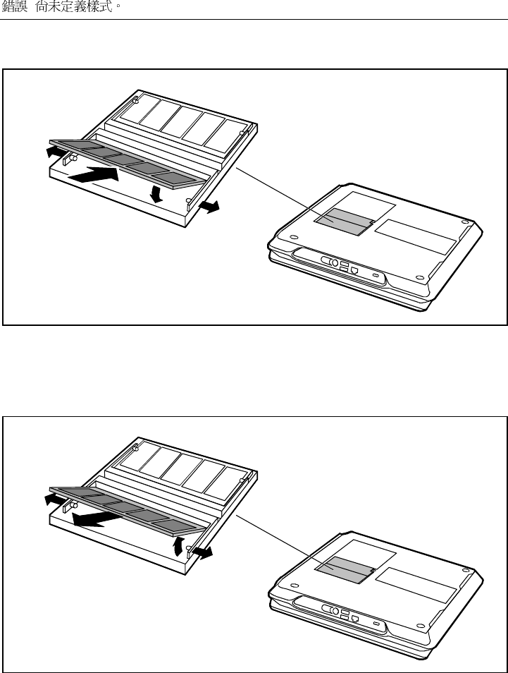
Removing cover
1
2
3
Ê Remove the screw (1).
Ê Lift the cover off the notebook in the direction
of the arrow (2).
Ê Pull off the cover from the notebook in the
direction of the arrow (3).
!
Installing memory modules
1
3
1
2
Ê Carefully push the two mounting clips outwards (1).
Ê Insert the memory module, contacts first, into the slot (2).
Ê Carefully push the memory module downwards until you feel it latch into place (3).
Removing memory modules
1
2
1
3
Ê Carefully push the two mounting clips outwards (1).
The memory module will flap upward (2).
Ê Pull the memory module out of its slot (3).
!
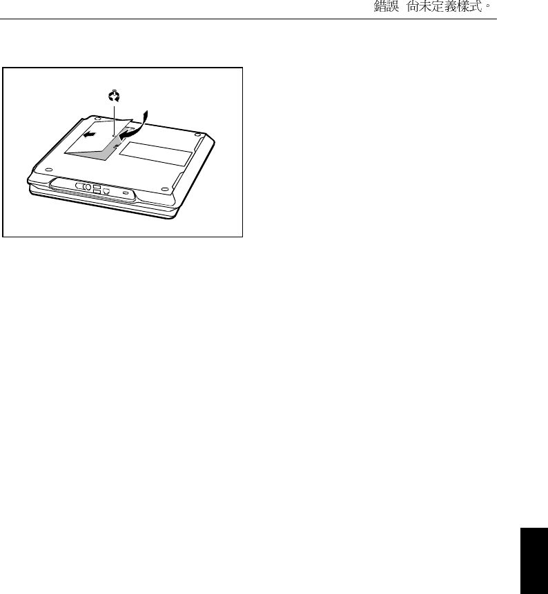
Mounting the cover
3
2
1
Ê Place the cover on its mounting location (1).
Ê Close the cover on the bottom of the
notebook (2).
Ê Fasten the cover with the screw (3).
Ê Refit the battery.
Ê Place the notebook right side up on a flat, stabile, nonslip surface.
Ê Reconnect the cables.

Technical data
Notebook
Processor
Chipset:
µPGA2 (Socket Mount)
Intel Pentium III 700 MHz to 1 GHz
Intel 815 EM
Main memory: Maximum 1 Gbyte PC 133 SO DIMM
2 slots for 512 Mbyte modules
JEDEC 144 pin
Possible modules: • CD-ROM drive, 24X speed
• DVD drive, 8/20X speed (CD-ROM)
• CD-RW drive, 24/4/8X speed
• Floppy disk drive
• Hard disk drive
• Battery
Electrical data
Regulations complied with: CE, EN60950, FCC Part 15 Class B, GS, Energy
Star, SITO
Protection class: II
Maximum power draw:
(notebook on with battery charging)
60 W
LCD screen
Display diagonal: 15-inch SVGA TFT
15-inch XGA TFT
LVDS-port
Graphics
Chip: AGP 4x, Advanced 3D, DVD accelerator
Video memory: 64 Mbyte with DDR support
Supported resolutions on external monitor:
Colour depth:
????
1024x768
24 bit
Audio
Sound: ESS Allegro ES1988

! !
Modem (Mini PCI modem)
Integrated modem: 56K, V.90, MC97 Codec, RI
LAN connector: Ethernet 10/100T, PME, AOL 2.0
Combo module: Modem and LAN
IEEE1394: 1394b
Bluetooth???
BlueTooth??? (Schreibweise???) Intel/Ericsson or Siemens USB
Input devices
Keyboard: 88 keys
Touchpad: 3 keys
Slots
PC Card slots (CardBus/PCMCIA): PCMCIA 2 x type II or 1 x type III,
PC card controller O2 Micro O2 711E1
Ports
PS/2 port: 6-pin mini DIN female connector
•Parallel port: 25-pin female connector, bi-directional, ECP
capable
•Monitor port: 15-pin female connector
•Serial port: 9-pin male connector, RS232C
•Microphone jack: connector, mono
•Headphone port: connector, stereo
•Video port: 7-pin mini DIN female connector
•Modem port: Female connector, RJ-11 once
•USB port (Universal Serial Bus): twice
•Infrared interface: IrDA 1.1 (Max 4M)
•LAN connector: Female connector, RJ-45
•Docking port: 240-pin Port Replikator II/II-L
•Kensington Lock
Environmental conditions
Environment class 7K1 DIN IEC 721
Environment class 7M2 DIN IEC 721
Temperature:
•Operating (7K1) 5 °C .... 35 °C
•Transport (2K2) -15 °C .... 60 °C
Dimensions
Width/depth/height: 340 mm/278 mm/39,5 mm
Weight: approx. 3,1 kg
Battery
Rated voltage: 19 V
Rated capacity 1.8 Ah (Li-Ion) / 58.3 W

! !
Charging time (when not in operation): approx. 2 hours
Operating time with a battery: approx. 3 hours (without power management)
Power adapter
Primary
•Rated voltage: 90 V to 240 V (automatic)
•Frequency: 50 Hz to 60 Hz (automatic)
•Max. rated current: 1,5 A
Secondary
•Rated voltage: 19 V
•Max. rated current: 3,16 A
You can readily order an additional power adapter and an additional power cable.

Index