R tron SNGATEMLT PCS Repeater Repote Monitor System User Manual
R-tron Inc. PCS Repeater Repote Monitor System
R tron >
User Manual
GateOne
Manual
GateOne
2
Contents
1. Configuration and Hardware connections .......................................................... 3
2. Setting for Command and Control ....................................................................... 4
3. Web GUI pages. ...................................................................................................... 8
4. Specifications ....................................................................................................... 14
1
User’s Manual
Safety Precautions
Safety Precautions
Warning
Opening the Tri MINI could result in electric shock and may cause severe injury.
Warning
Connect the equipment frame ground to building ground.
Warning
Operating the Tri MINI with antennas in very close proximity facing each other
could lead to severe damage to the repeater.
Caution
RF EXPOSURE INFORMATION
A minimum separation distance of 7.9 inches (20cm) must be maintained between
the user and the external antenna of repeater to satisfy FCC RF exposure
requirements. For more information about RF exposure, please visit the FCC
website at www.fcc.gov
Caution
This equipment is for indoor use and enables the communication wiring to
communicate only inside the building.
3
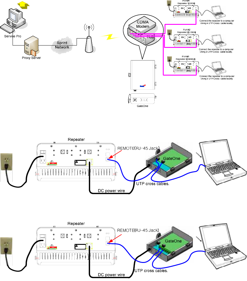
1. Configuration and Hardware connections
* Overall configuration
DONOR
ANTE N N A
DANGER
RISK OF EL ECTRI C SHO CK
110 -12 5V ac
AC I N
SERVI C E
ANTENNA
DL Output
MON.
UL Output
MON.
Note
external devices only
Power o utle t for compatible
DC OUT
+12Vdc or -12 Vdc
MAX 2A
LOCAL
REMOTE
ALARM
DONOR
ANTENNA
DANGER
RISK OF EL ECTRI C SHO CK
110 -1 25V ac
AC IN
SERVI CE
ANTENNA
DL Output
MON.
UL Output
MON.
Note
external devices only
Power outl et for c ompatible
DC OUT
+12V dc or -12 Vd c
MAX 2A
LOCAL
REMOTE
ALARM
DONOR
ANTENNA
DANGER
RISK OF EL ECTRI C SHO CK
110 -1 25V ac
AC IN
SERVI CE
ANTENNA
DL Output
MON.
UL Output
MON.
Note
external devices only
Power outl et for c ompatible
DC OUT
+12V dc or -12 Vd c
MAX 2A
LOCAL
REMOTE
ALARM
GateOne
* Hardware connections
DONOR
AN TE NN A
DA NGER
R ISK O F EL ECTR I C SHO CK
11 0 -1 25Vac
AC IN
SERVICE
ANTENNA
DL Output
MON.
UL Out put
MON.
Not e
external devices only
Po we r outl et f or c ompatible
DC OUT
+ 12V dc o r -12 Vd c
MAX 2A
LOCAL
REMOTE
ALARM
RSN-GATE-SGL
DONOR
AN TE NN A
DA NGER
R ISK O F EL ECTR I C SHO CK
11 0 -1 25Vac
AC IN
SERVICE
ANTENNA
DL Output
MON.
UL Out put
MON.
Not e
external devices only
Po we r outl et f or c ompatible
DC OUT
+ 12V dc o r -12 Vd c
MAX 2A
LOCAL
REMOTE
ALARM
RSN-GATE-MLT
* GateOne backwards compatibility with HB1900.
4
2. Setting for Command and Control
* GateOne operates on a customer provided PC based platform with the following system
requirements.
Windows® XP Strong recommended
128 MB RAM or more
Pentium Ⅲ processor or more keyboard
RJ-45 jack
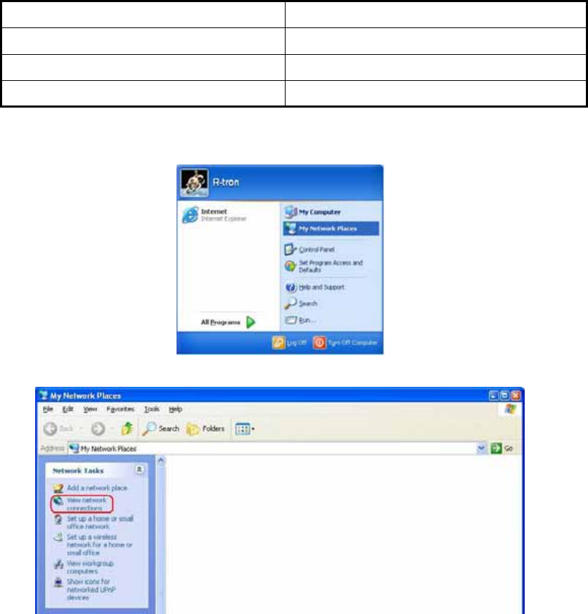
Step 1 Open My Network Places.
Step 2 Click the “View network connections”.
5
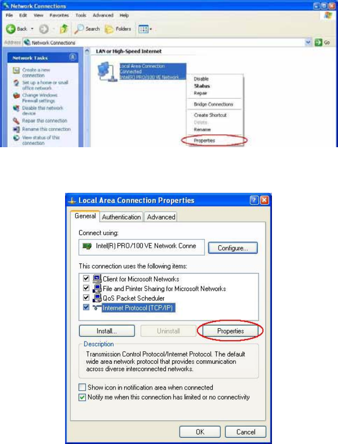
Step 3 Push the right button of mouse and select the properties.
Step 4 Click the properties of TCP/IP.
6
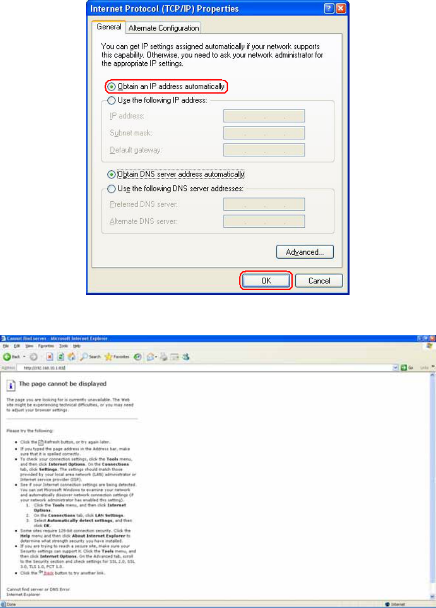
Step 5 Set the values and OK as the following. Close all windows.
Step 6 Open a new explorer window.

7
Step 7 Type http://192.168.10.1:83 in the address box and press “Enter” key.
Step 8 Login with “admin” of ID and “1234” of password and “OK”.
8
3. Web GUI pages.
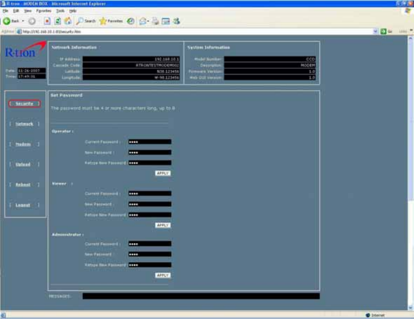
A. Security page
Three logon passwords; Operator, Viewer, and Administrator, can be authorized on the security
page.
* Logon as Operator: An operator has all authorization of changing, monitoring, and controlling
except parameters on the Security page.
* Logon as Viewer: Viewer is able to show the information of MODEM box only.
* Logon as Administrator: Administrator has all authorization of changing, monitoring, and
controlling.
9
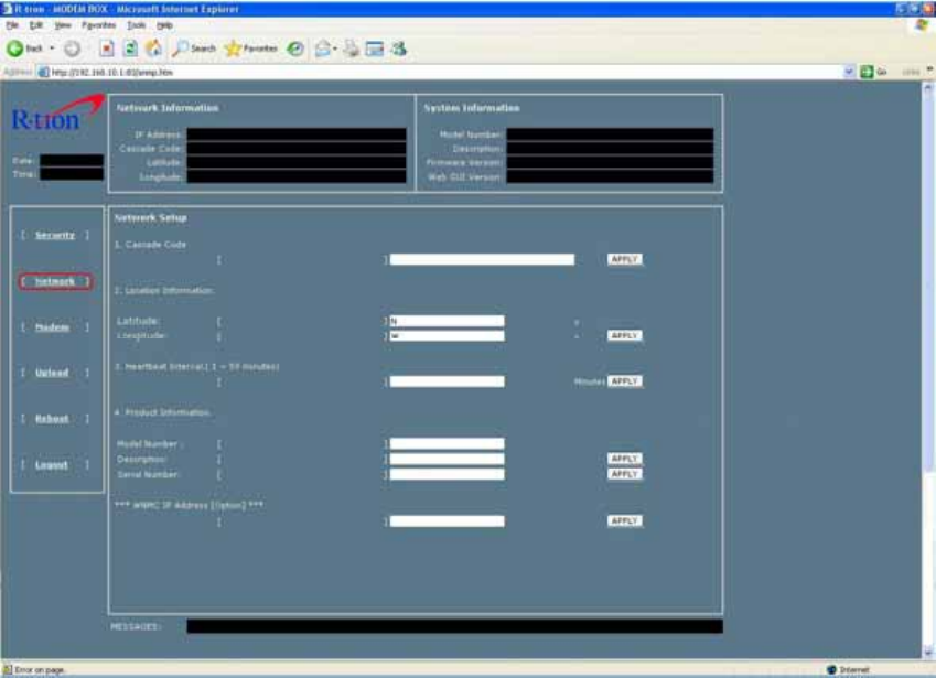
B. Network page
a. Cascade Code: Type in the pre-assigned code. Otherwise, you cannot access system
setup.
b. Location Information: Takes the latitude and longitude, otherwise you cannot access
system setup.
[Example]
(‘Ν/S’ | ‘Ε/W’) (+|-) ddd.dddddd: (Latitude: N 39.006597 Longitude: W 122.152390)
c. Product Information: This is for manufacturer used only. Do not change this value.
d. NMC Server IP: Do not change the value. Otherwise Remote Access may not work.
10
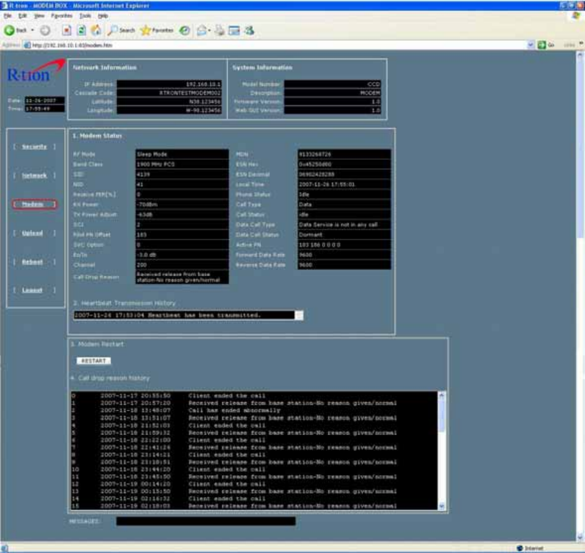
C. Modem page
The Modem Page shows totally all information related with repeater and other devices.
11
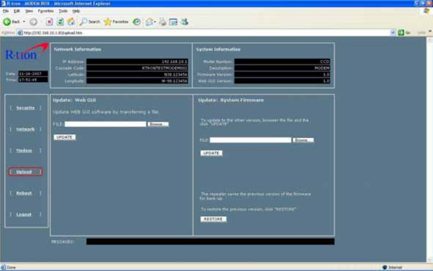
D. Upload page
The newest Web GUI and System firmware are able to be updated on this page.
12
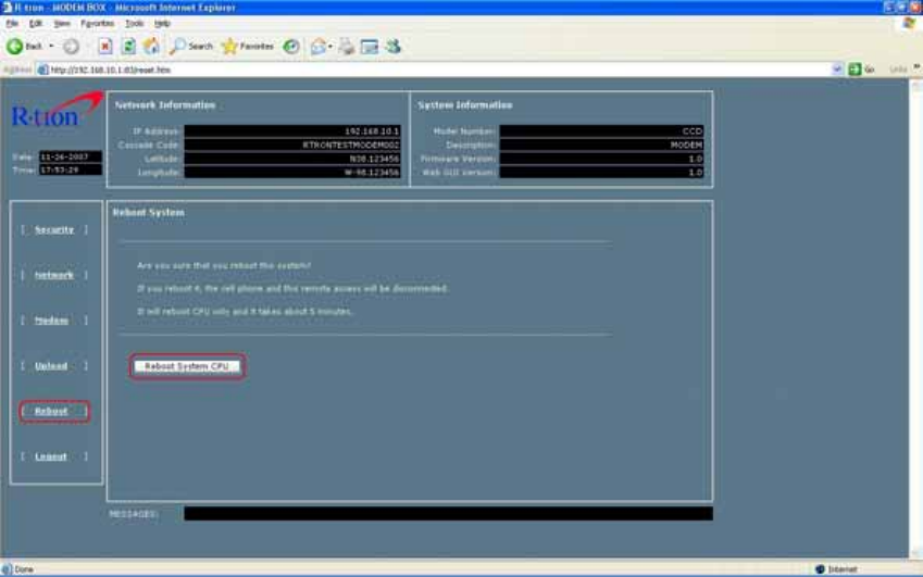
E. Reboot page
Clicking “Reboot System CPU” makes restart up the operating system on the Micro Processor
Unit.

13
F. L o g o u t
Click the “Logout” and press the “OK” to exit current logon.
14
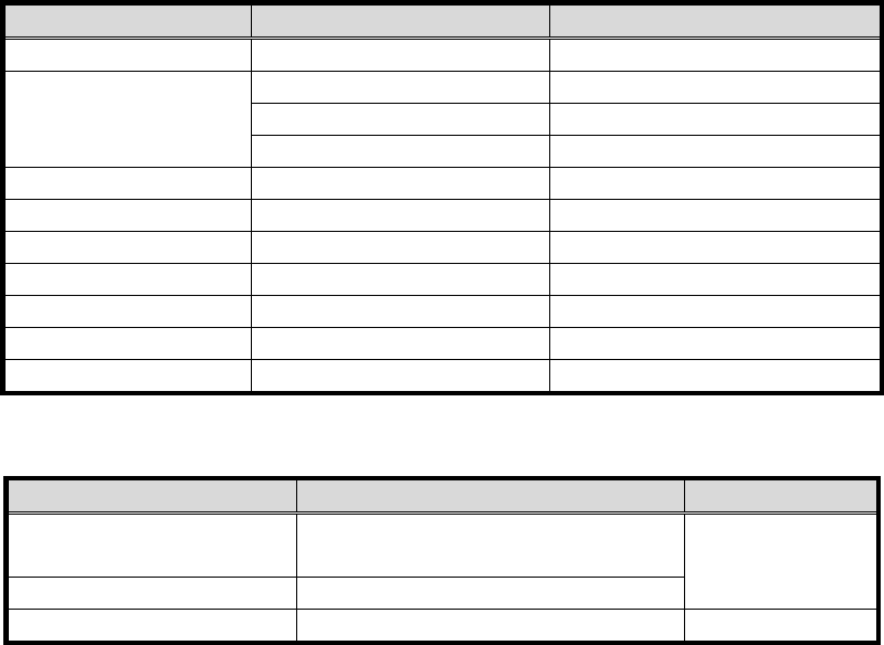
4. Specifications
a. Electrical Specification
Item Specifications Remark
CPU S3c2410A: 16/32-bit RICS
Memory
NOR Flash: 4M byte Boot Loader, Linux Kernel
NAND Flash: 32M byte Ram disk, Application Program
SDRAM: 32M byte
Local Craft Port RJ-45
External Repeater port RJ-45 8port HUB IEEE 802.3 10Base-T
Modem Kyocera M200
Power supply DC +12V / Max 1A
Operating temperature -10℃ ~ 50℃
Storage temperature -20℃~60℃
Humidity 95 %
b. Mechanical Specification
Item Specification Remark
Dimension 180(W)x230(D)x80(H)_mm
7.08(W)x9.05(D)x3.15(H)_inch Not commercial
product
Weight 2kg (4.4lbs)
Power Supply Connector 4 pin AMP connector (female Type) AMP 206430