R tron SNIDEN30C iDen Mini Repeater User Manual
R-tron Inc. iDen Mini Repeater
UserManual.wiki
>
R tron
>
SNIDEN30C User Manual
>
Part 2
Contents
1.
Part 1
2.
Part 2
Part 2
Navigation menu
Upload a User Manual
Namespaces
Wiki Guide
HTML
PDF
Info
Views
User Manual
Discussion / Help
Navigation
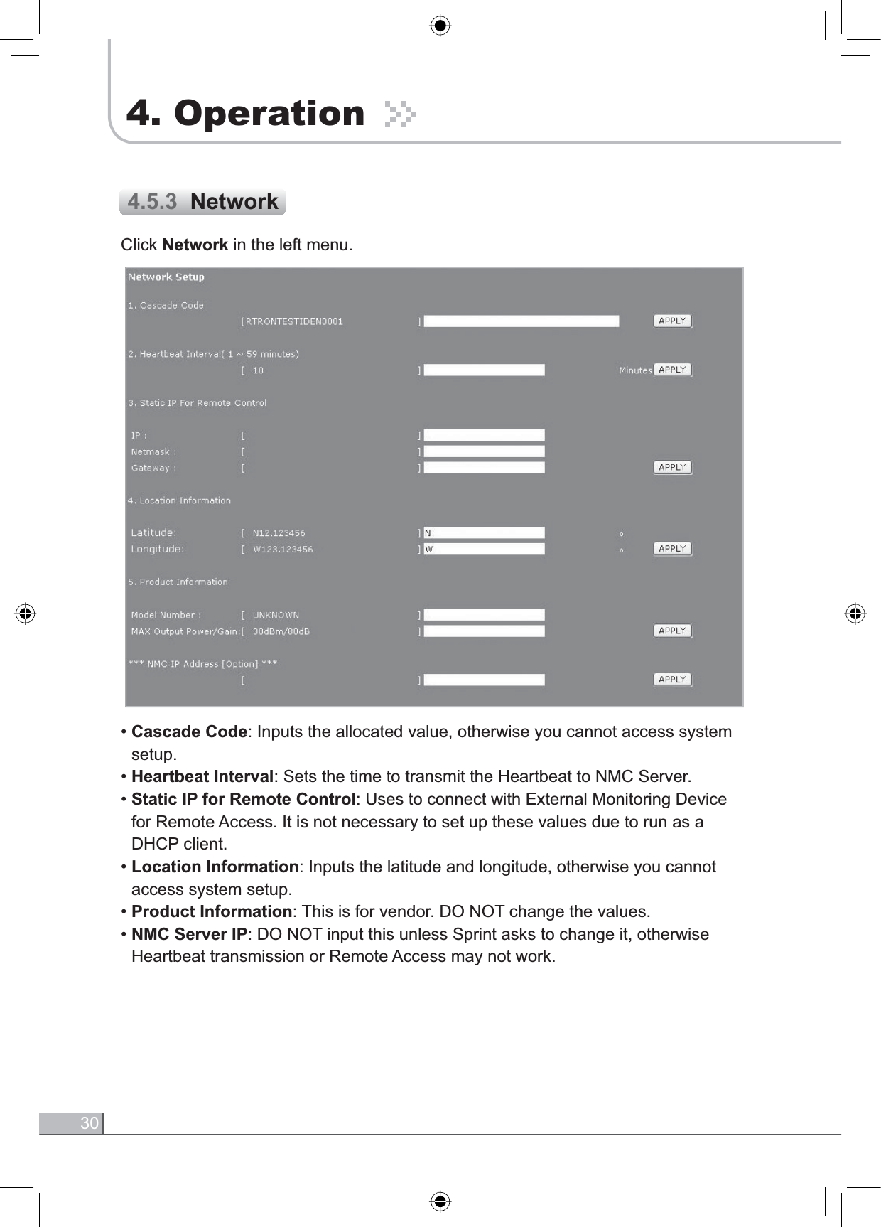
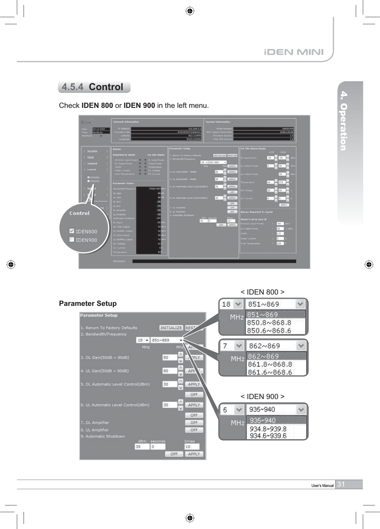
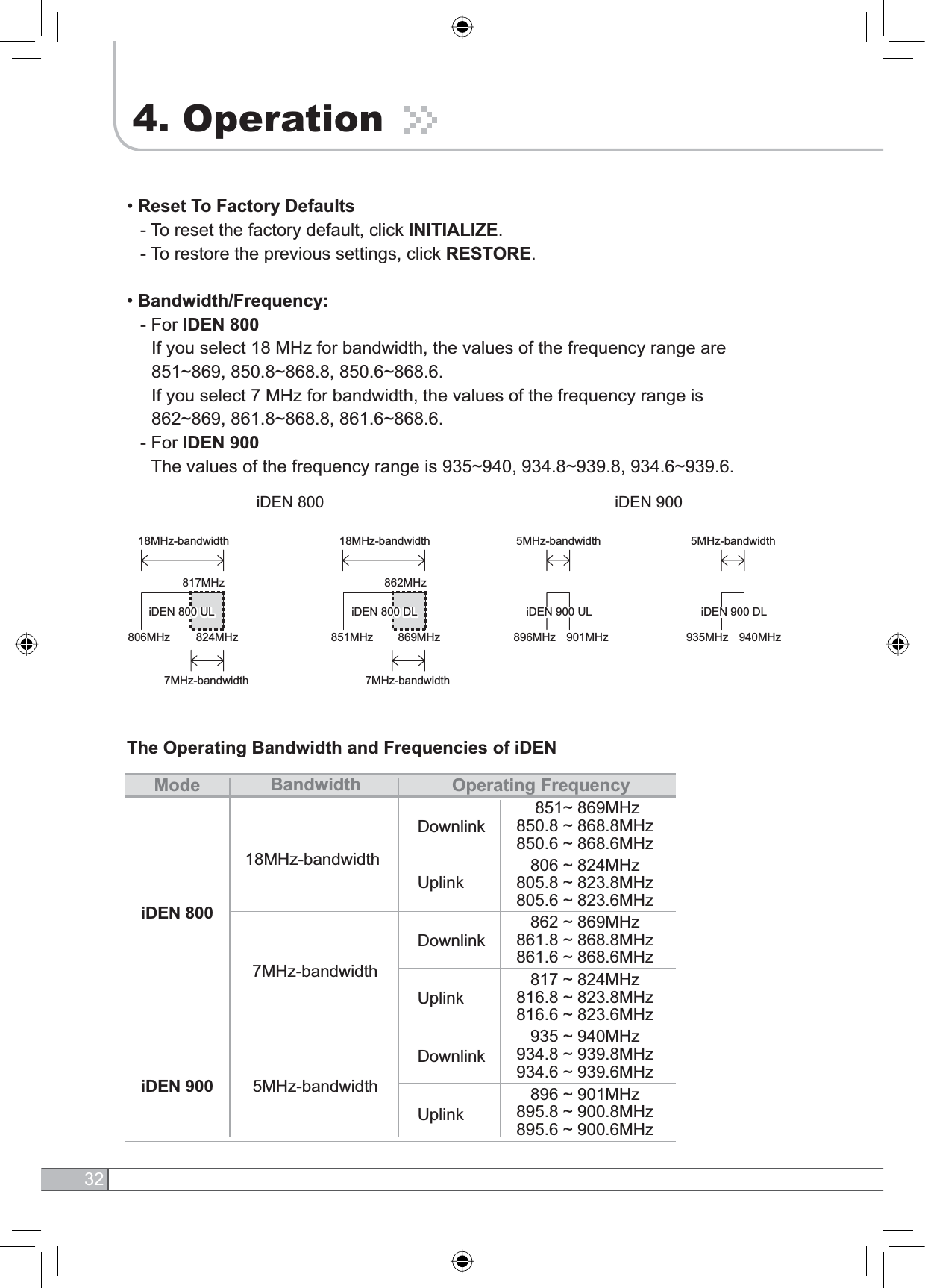
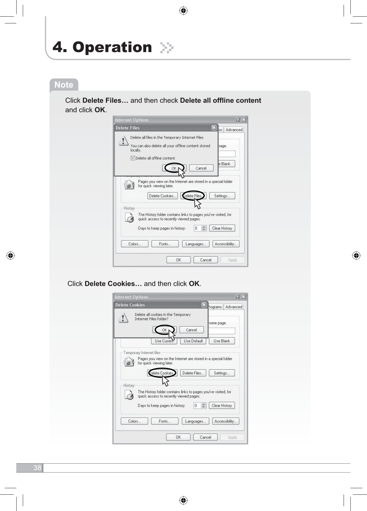
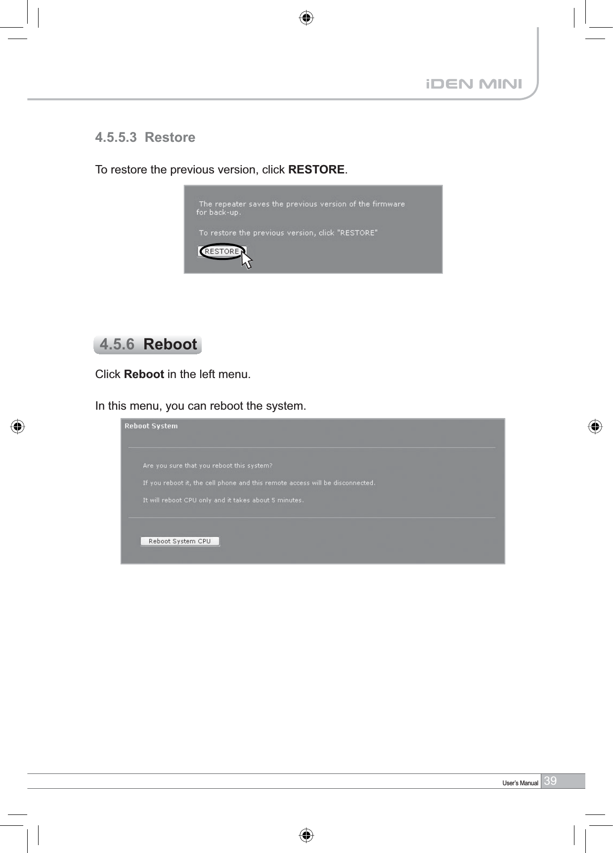
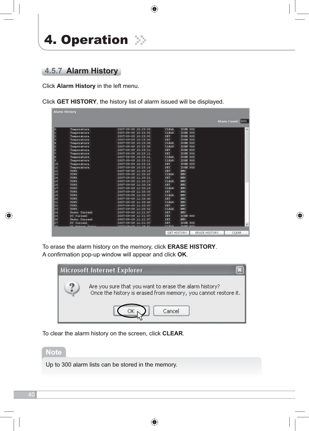
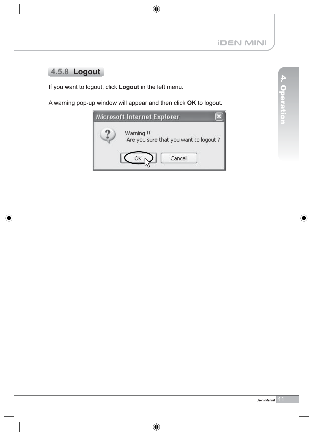
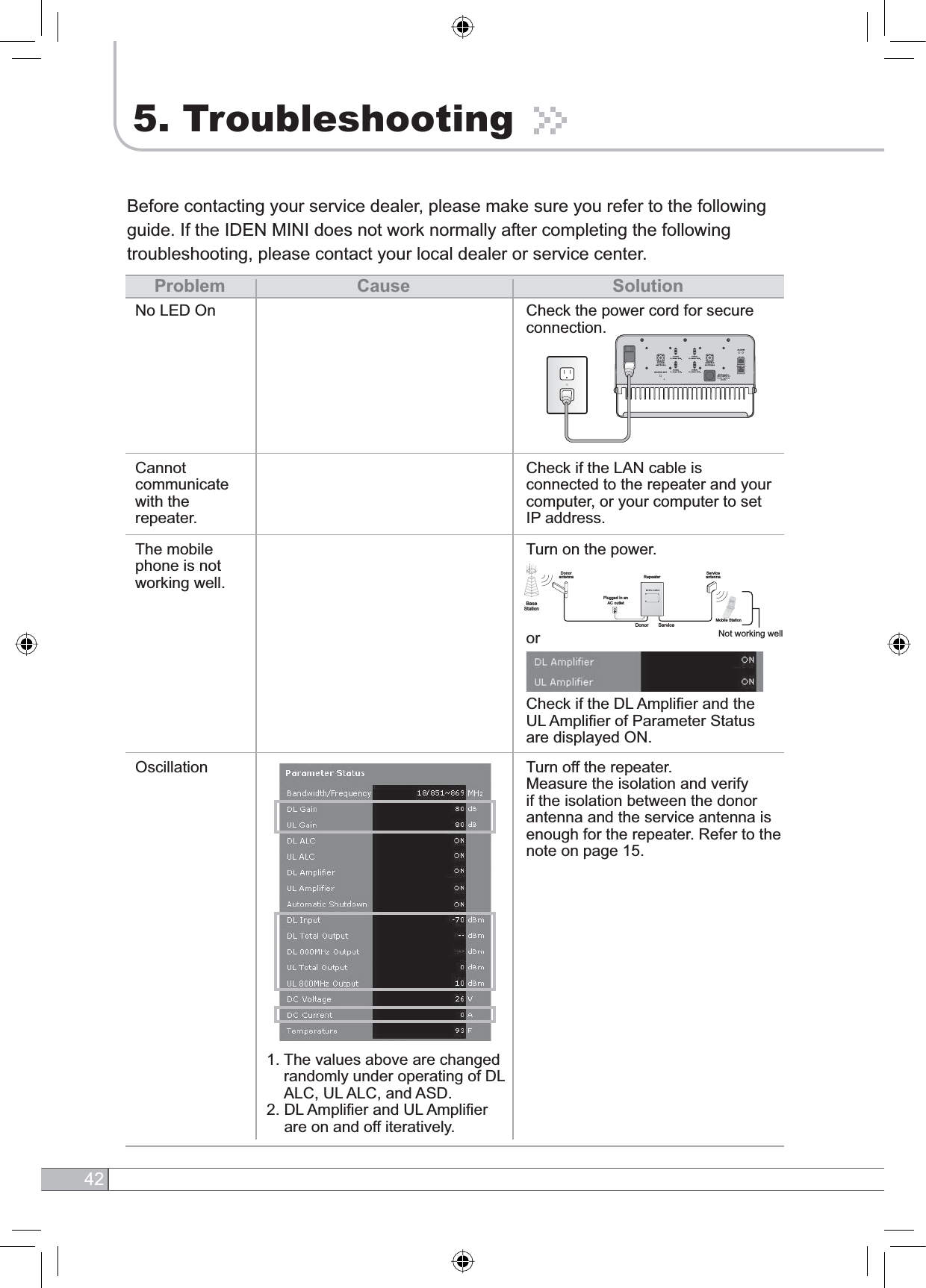
![33User’s Manual4. Operation•DL Gain: Type values between 50 and 80 and then click APPLY.•UL Gain: Type values between 50 and 80 and then click APPLY.NotePlease make sure DL Automatic Level Control,UL Automatic Level Controlare turned off before the gain setup. Otherwise, it may cause an error.•DL Automatic Level Control: Type under 30 and then click APPLY and ON.•UL Automatic Level Control: Type under 30 and then click APPLY and ON. [Example]For the repeater with 30dBm Maximum Output power, 80dB Maximum Gain G%*DLQFRQWUROUDQJHĺ,ILQSXWVLJQDOLV%PDQG$/&LVVHWDVG%Pthe gain will be 60dB to adjust to the level. If input signal is -55dBm, the output power will be 25dBm by the limitation of the maximum gain even though the ALC is set as 30dBm.•Automatic Shutdown: Type the desired values for dBm,seconds and timesand then click APPLY and ON. (e.g. 35 dBm, 3 seconds, 10 times)[Example]For the repeater with 30dBm Maximum Output power, 80dB Maximum Gain /30dB Gain control range, Assuming ASD Level: 35dBm, ASD Time: 3second, ASD Count: 10. If the output power is 35dBm (ASD LEVEL) and higher for some reasons, the repeater will have shut down for 3 seconds (ASD TIME). If this repeats 10 times (ASD COUNT), the repeater will shut down completely.](https://usermanual.wiki/R-tron/SNIDEN30C.Part-2/User-Guide-849423-Page-12.png)