Contents
- 1. Part 1
- 2. Part 2
Part 2
22
4. Operation
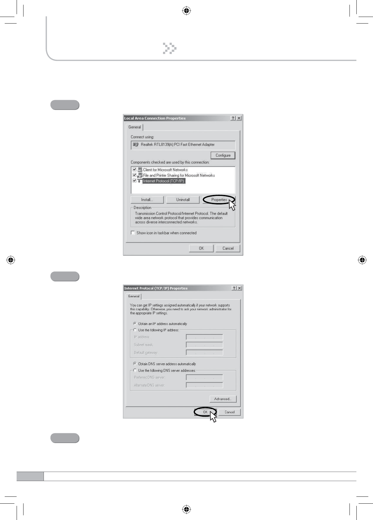
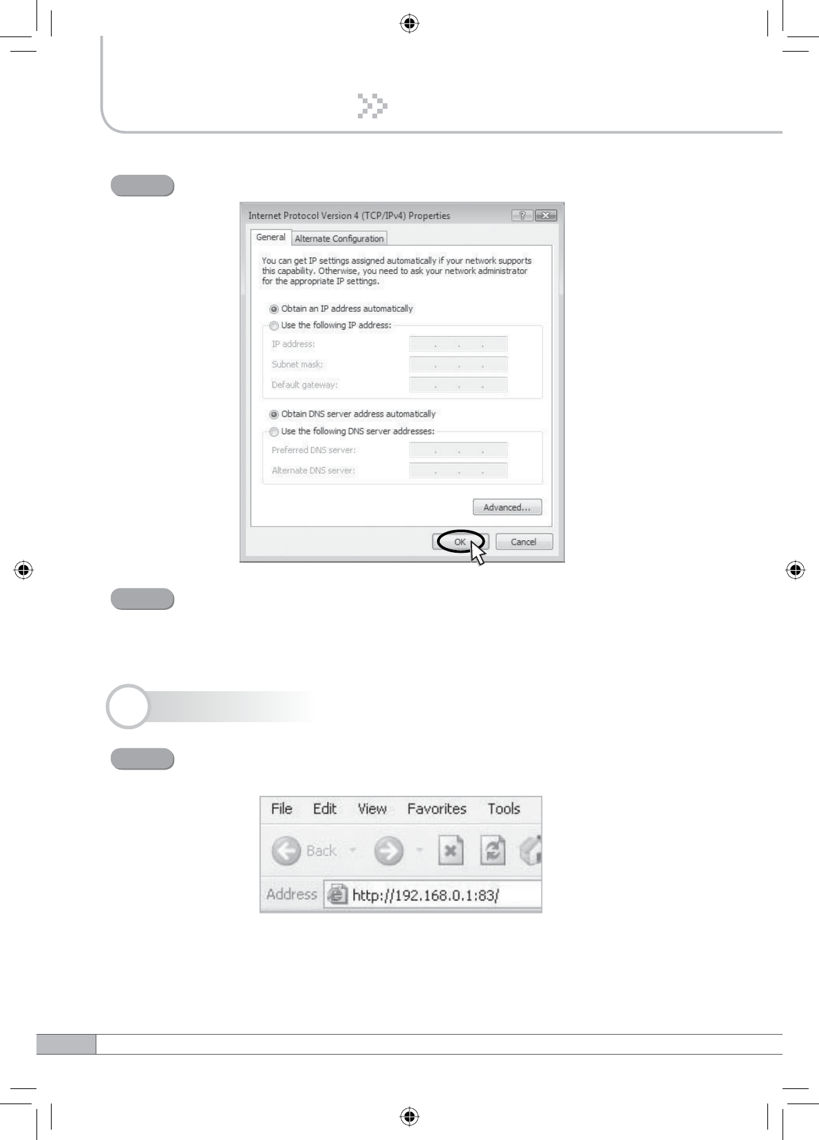
Select Internet Protocol (TCP/IP) and click Properties.
Step 3
Check Obtain an IP address automatically and click OK.
Step 4
Close all windows.
Step 5
23
User’s Manual
4. Operation
4.3.3 Windows Vista
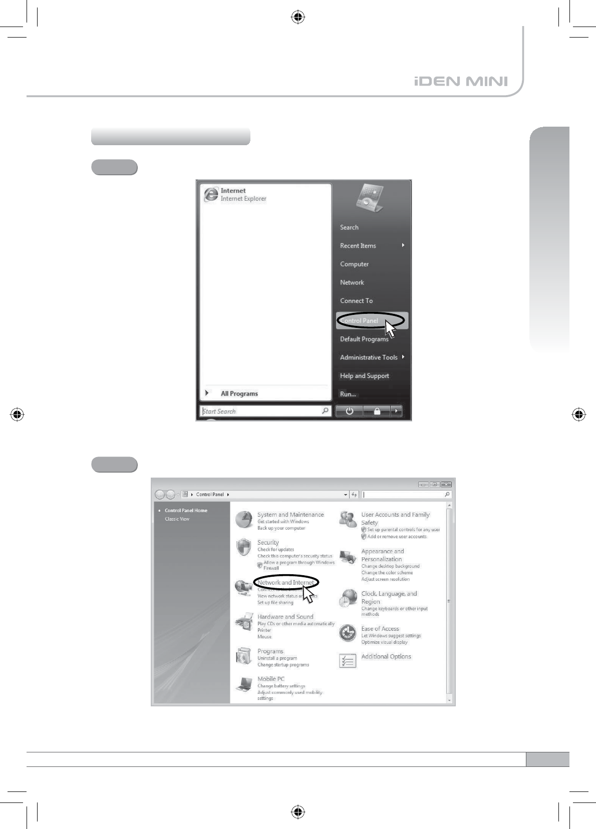
Click the Start button and Control Panel.
Step 1
Click Network and Internet.
Step 2
24
4. Operation
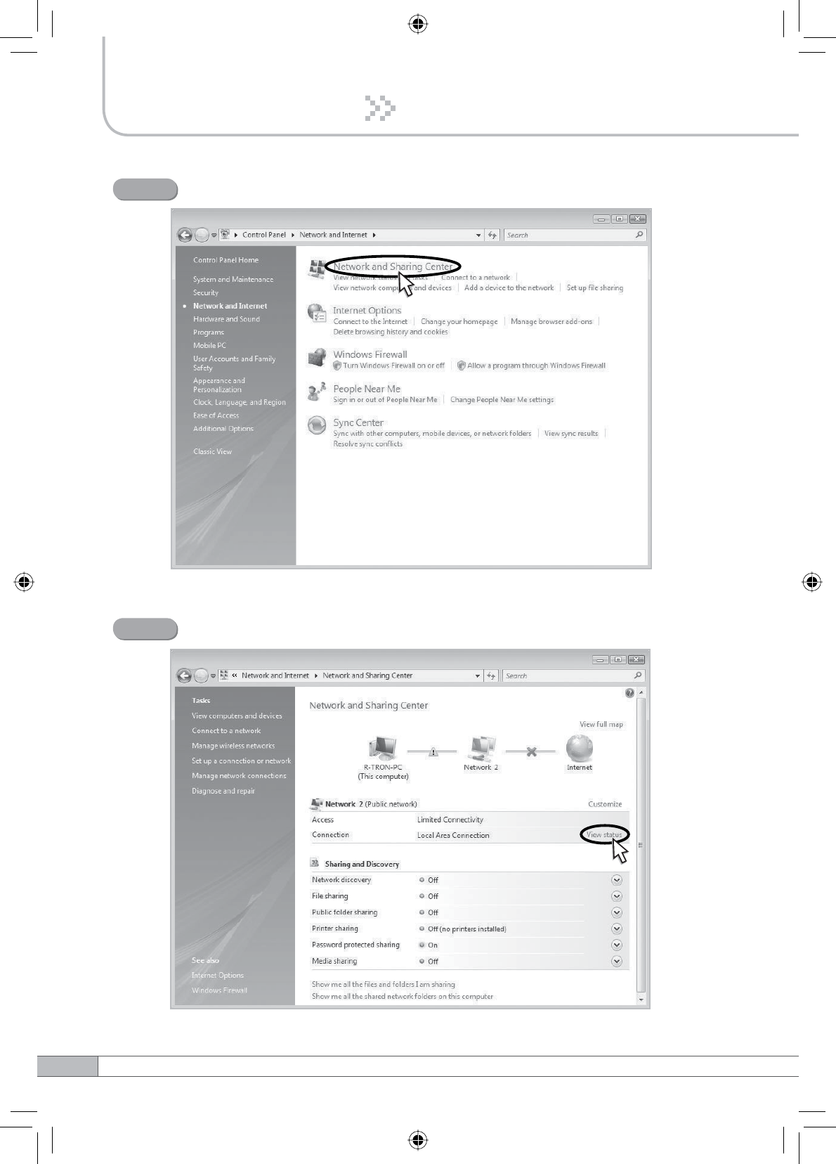
Click Network and Sharing Center.
Step 3
Click View status of Local Area Connection.
Step 4
25
User’s Manual
4. Operation
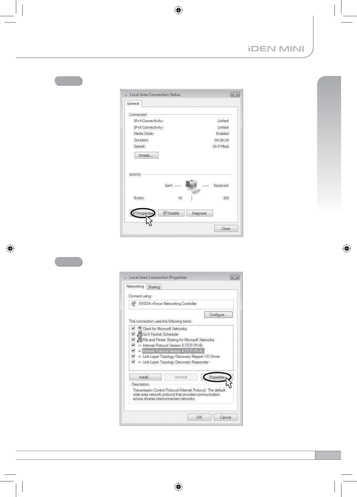
Click Properties and a caution pop-up window will appear. Click OK.
Step 5
Select Internet Protocol Version 4 (TCP/IPv4) and click Properties.
Step 6
26
4. Operation
4.4 System Login
Check Obtain an IP address automatically and click OK.
Step 7
Close all windows.
Step 8
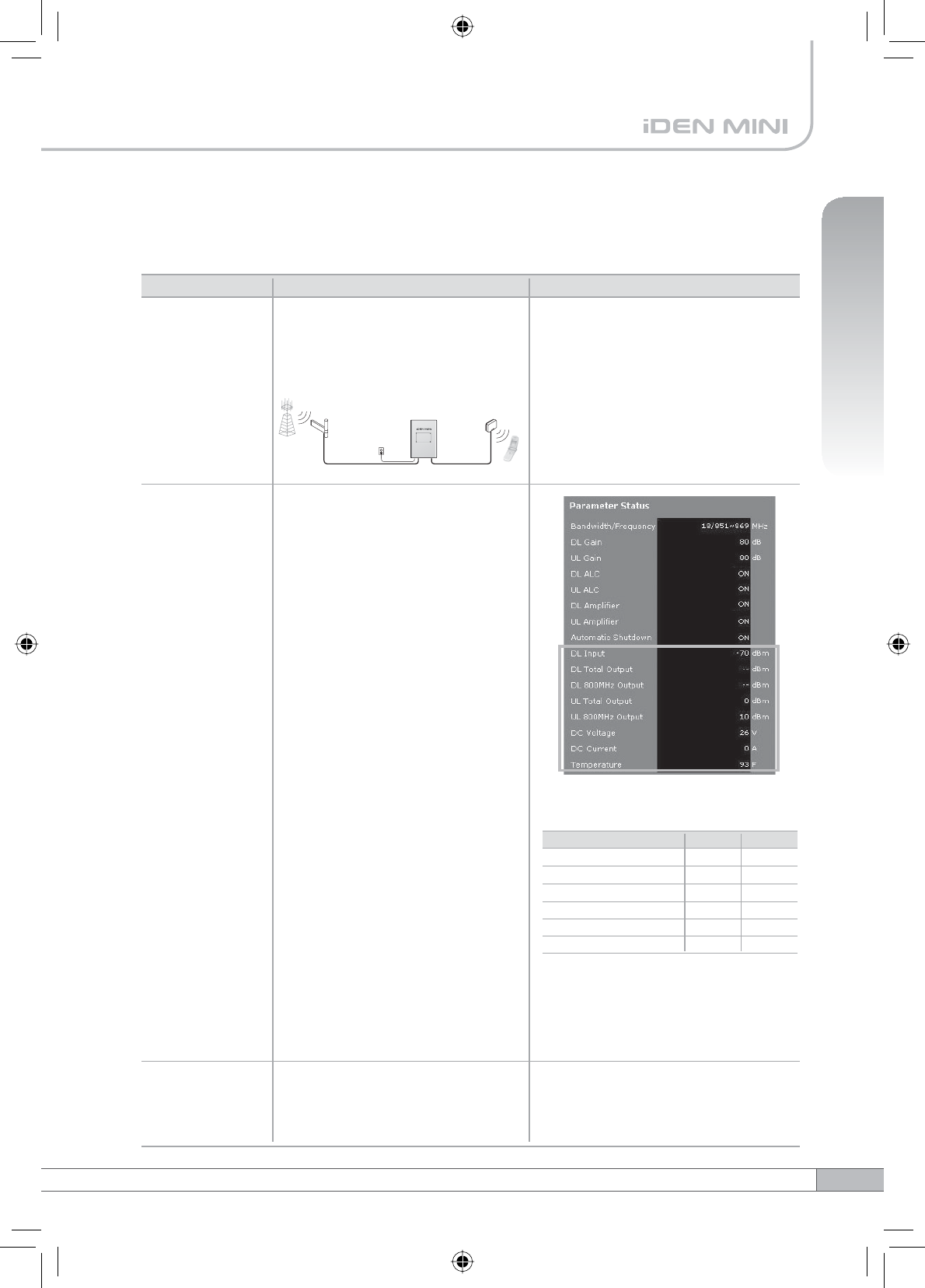
Open your Web browser and type “192.168.0.1:83” into the URL
address box. Then press the Enter key.
Step 1
27
User’s Manual
4. Operation
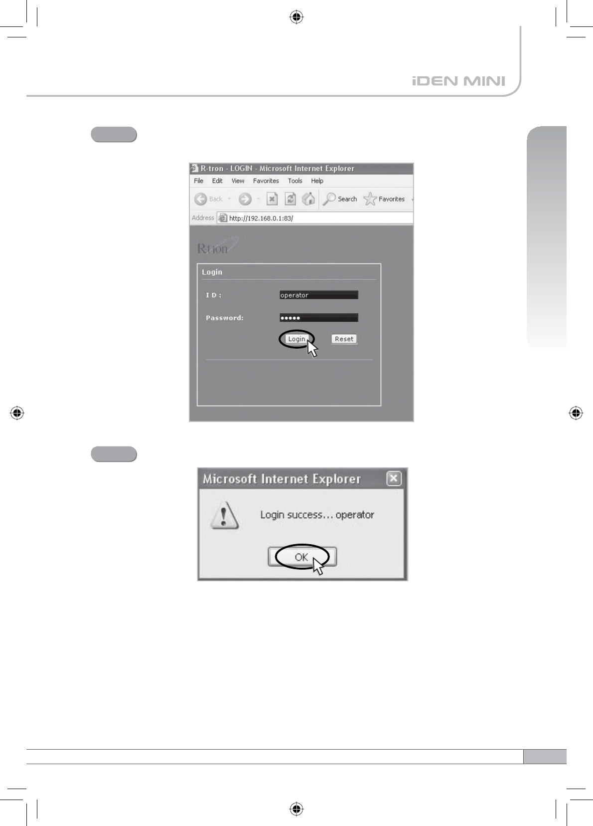
The logon screen will appear. Type “operator” for the ID and “rtron” for
the password and then click OK.
Step 2
The pop-up message for the login success will appear. Click OK.
Step 3
28
4. Operation
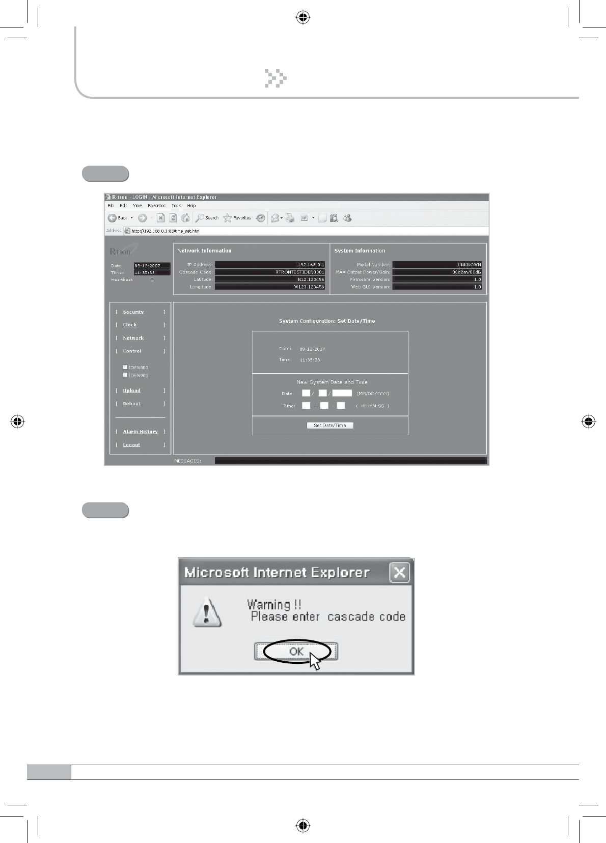
The login process is complete. The Initial screen will appear.
Step 4
In case of the initial login, you should input Cascade Code and Location
Information of Network Setup. Otherwise a warning pop-up window will
appear and you cannot access any of the menus.
Step 5
29
User’s Manual
4. Operation
Operator has no authorization to access this menu.
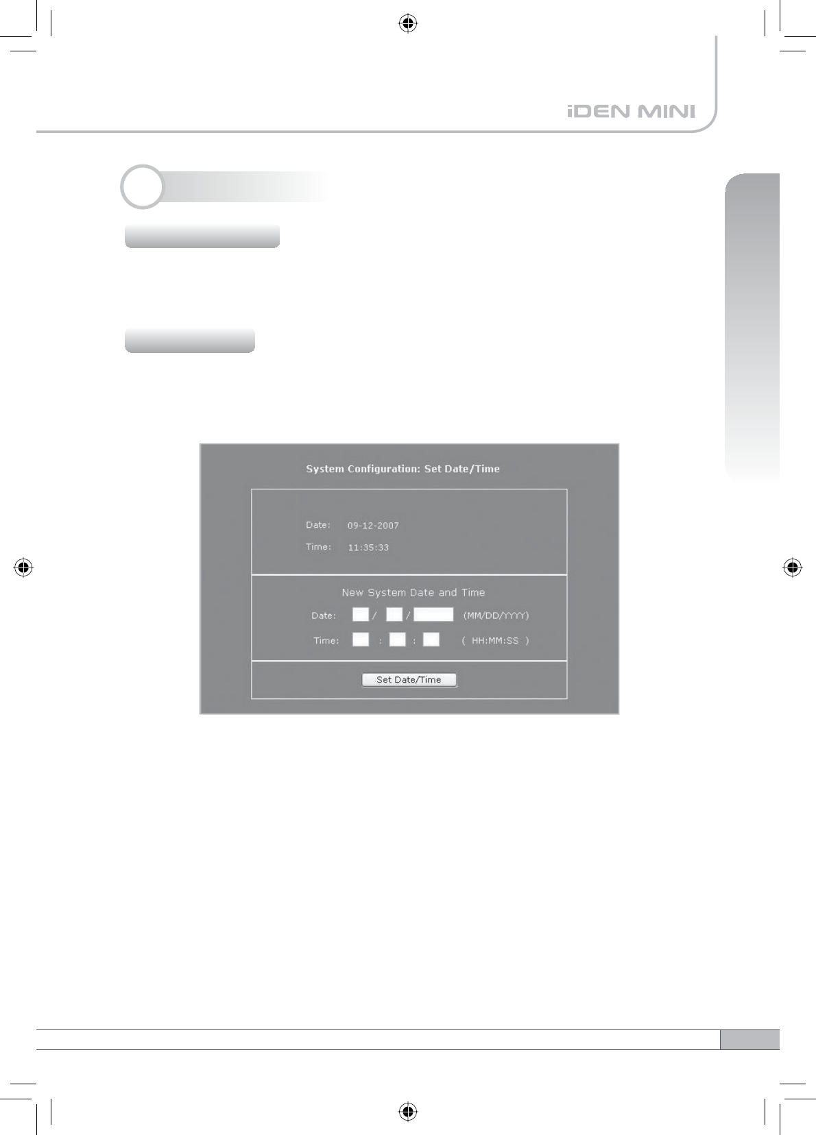
Click Clock in the left menu.
In this menu, you can set the date and the time.
Click Set Date/Time.
4.5 System Setup
4.5.1 Security
4.5.2 Clock
30
4. Operation
Click Network in the left menu.
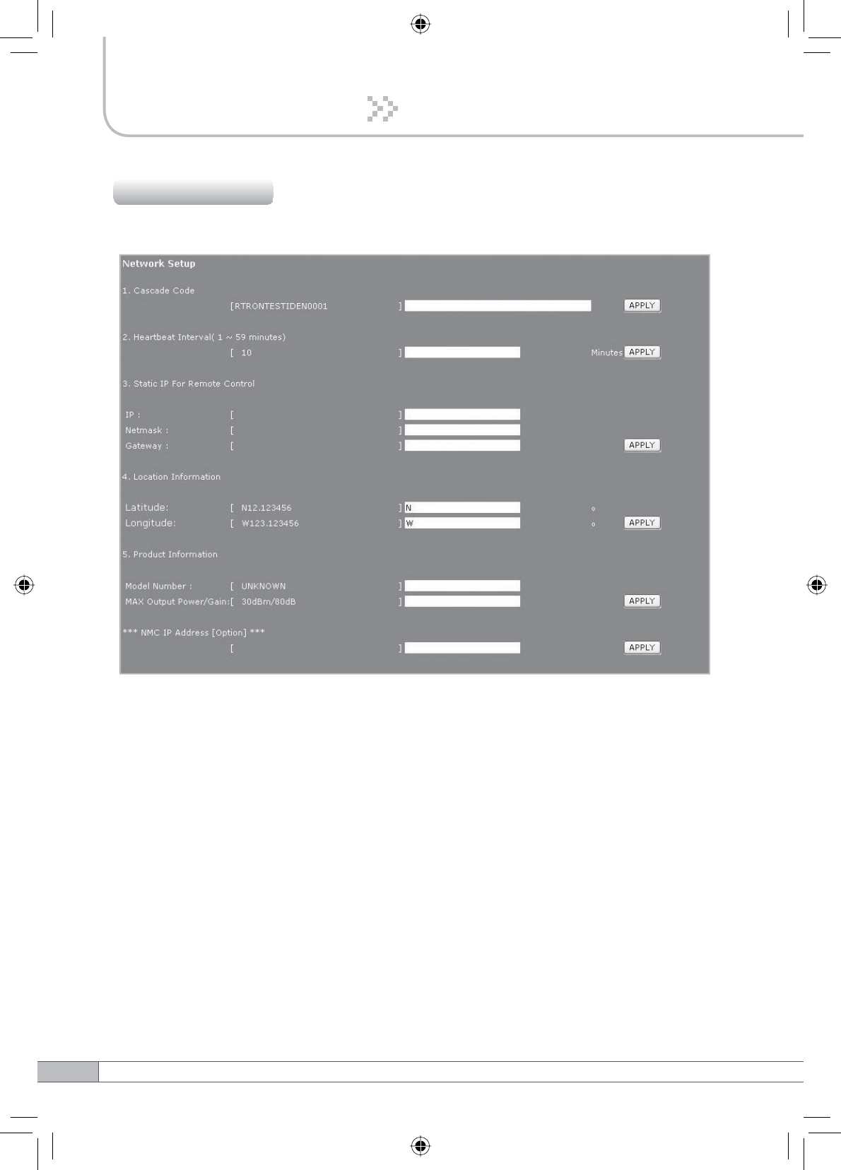
4.5.3 Network
•Cascade Code: Inputs the allocated value, otherwise you cannot access system
setup.
•Heartbeat Interval: Sets the time to transmit the Heartbeat to NMC Server.
•Static IP for Remote Control: Uses to connect with External Monitoring Device
for Remote Access. It is not necessary to set up these values due to run as a
DHCP client.
•Location Information: Inputs the latitude and longitude, otherwise you cannot
access system setup.
•Product Information: This is for vendor. DO NOT change the values.
•NMC Server IP: DO NOT input this unless Sprint asks to change it, otherwise
Heartbeat transmission or Remote Access may not work.
31
User’s Manual
4. Operation
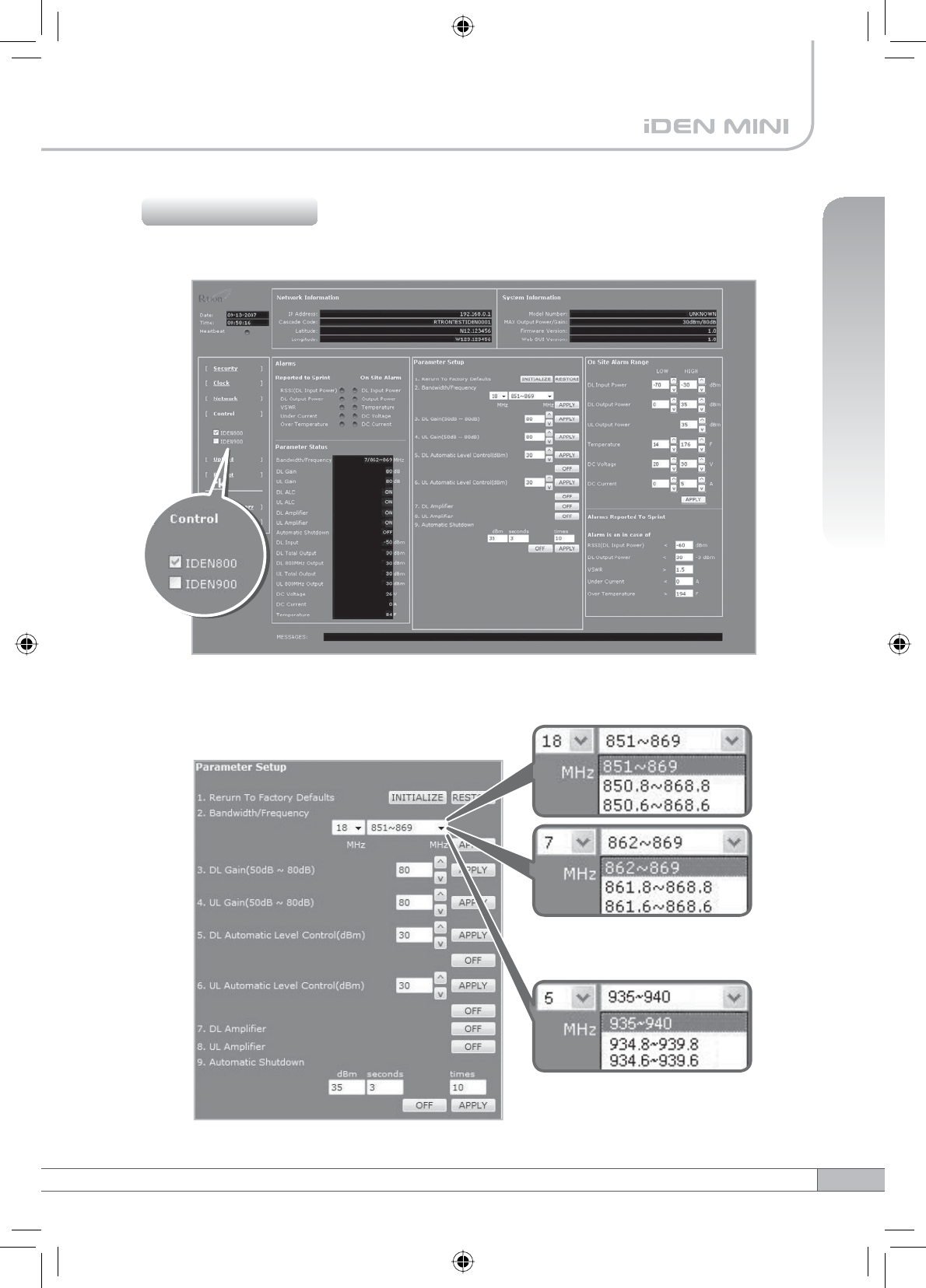
Check IDEN 800 or IDEN 900 in the left menu.
4.5.4 Control
Parameter Setup
< IDEN 900 >
< IDEN 800 >
32
4. Operation
•Reset To Factory Defaults
- To reset the factory default, click INITIALIZE.
- To restore the previous settings, click RESTORE.
•Bandwidth/Frequency:
- For IDEN 800
If you select 18 MHz for bandwidth, the values of the frequency range are
851~869, 850.8~868.8, 850.6~868.6.
If you select 7 MHz for bandwidth, the values of the frequency range is
862~869, 861.8~868.8, 861.6~868.6.
- For IDEN 900
The values of the frequency range is 935~940, 934.8~939.8, 934.6~939.6.
817MHz
18MHz-bandwidth
824MHz806MHz
862MHz
869MHz851MHz 901MHz896MHz
iDEN 800 iDEN 900
940MHz935MHz
7MHz-bandwidth
18MHz-bandwidth 5MHz-bandwidth 5MHz-bandwidth
7MHz-bandwidth
iDEN 800 UL iDEN 800 DL iDEN 900 UL iDEN 900 DLiDEN 800 UL iDEN 800 DL iDEN 900 UL iDEN 900 DL
The Operating Bandwidth and Frequencies of iDEN
Mode Bandwidth
18MHz-bandwidth
iDEN 800
iDEN 900
Operating Frequency
Downlink
851~ 869MHz
850.8 ~ 868.8MHz
850.6 ~ 868.6MHz
Uplink
806 ~ 824MHz
805.8 ~ 823.8MHz
805.6 ~ 823.6MHz
7MHz-bandwidth
Downlink
862 ~ 869MHz
861.8 ~ 868.8MHz
861.6 ~ 868.6MHz
Uplink
817 ~ 824MHz
816.8 ~ 823.8MHz
816.6 ~ 823.6MHz
5MHz-bandwidth
Downlink
935 ~ 940MHz
934.8 ~ 939.8MHz
934.6 ~ 939.6MHz
Uplink
896 ~ 901MHz
895.8 ~ 900.8MHz
895.6 ~ 900.6MHz

33
User’s Manual
4. Operation
•DL Gain: Type values between 50 and 80 and then click APPLY.
•UL Gain: Type values between 50 and 80 and then click APPLY.
Note
Please make sure DL Automatic Level Control,UL Automatic Level Control
are turned off before the gain setup. Otherwise, it may cause an error.
•DL Automatic Level Control: Type under 30 and then click APPLY and ON.
•UL Automatic Level Control: Type under 30 and then click APPLY and ON.
[Example]
For the repeater with 30dBm Maximum Output power, 80dB Maximum Gain
G%*DLQFRQWUROUDQJHĺ,ILQSXWVLJQDOLV%PDQG$/&LVVHWDVG%P
the gain will be 60dB to adjust to the level.
If input signal is -55dBm, the output power will be 25dBm by the limitation of the
maximum gain even though the ALC is set as 30dBm.
•Automatic Shutdown: Type the desired values for dBm,seconds and times
and then click APPLY and ON. (e.g. 35 dBm, 3 seconds, 10 times)
[Example]
For the repeater with 30dBm Maximum Output power, 80dB Maximum Gain
/30dB Gain control range, Assuming ASD Level: 35dBm, ASD Time: 3second,
ASD Count: 10.
If the output power is 35dBm (ASD LEVEL) and higher for some reasons, the
repeater will have shut down for 3 seconds (ASD TIME). If this repeats 10 times
(ASD COUNT), the repeater will shut down completely.
34
4. Operation
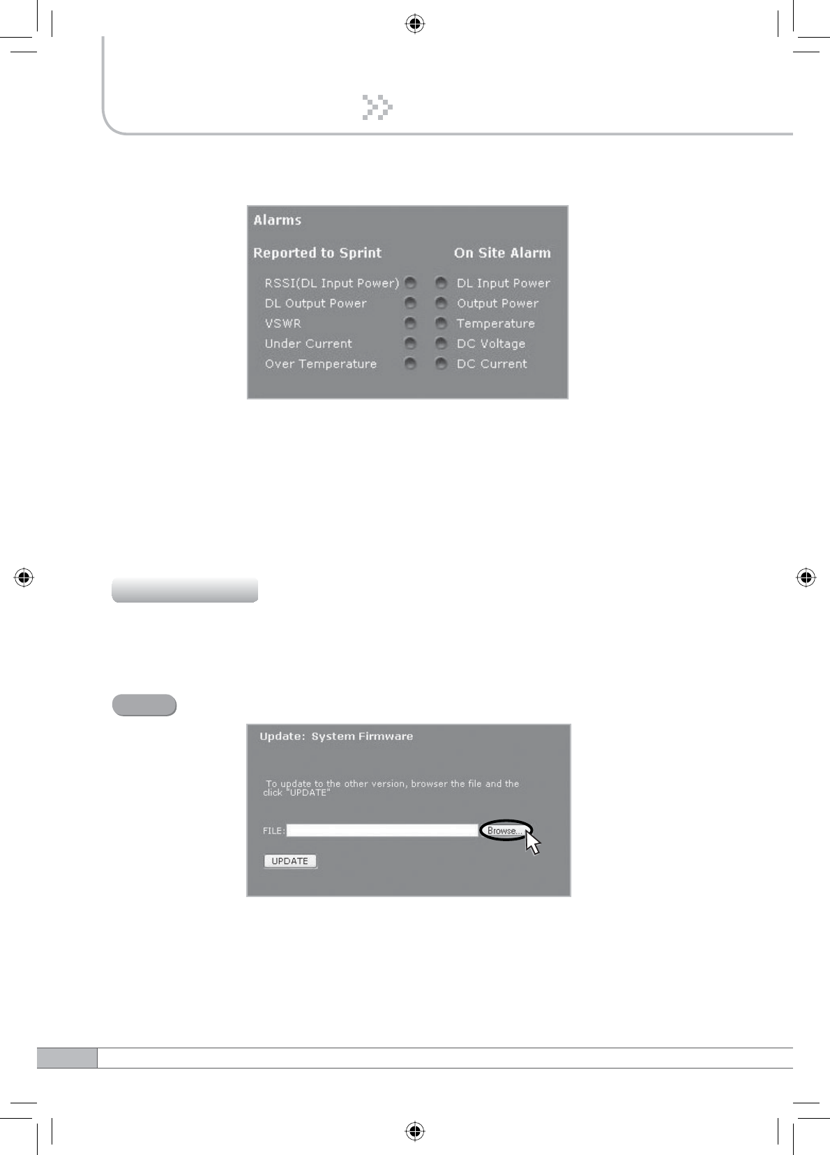
Alarms
•Reported to Sprint : If an alarm occurs, the repeater will report directly to Sprint
as a SNMP Trap so the LED of ALARM on the repeater does not blink.
•On Site Alarm : If an alarm occurs, the LED of ALARM on the repeater will blink.
For this alarm issued, refer to the troubleshooting.
Click Upload in the left menu.
4.5.5.1 Update: System Firmware
4.5.5 Upload
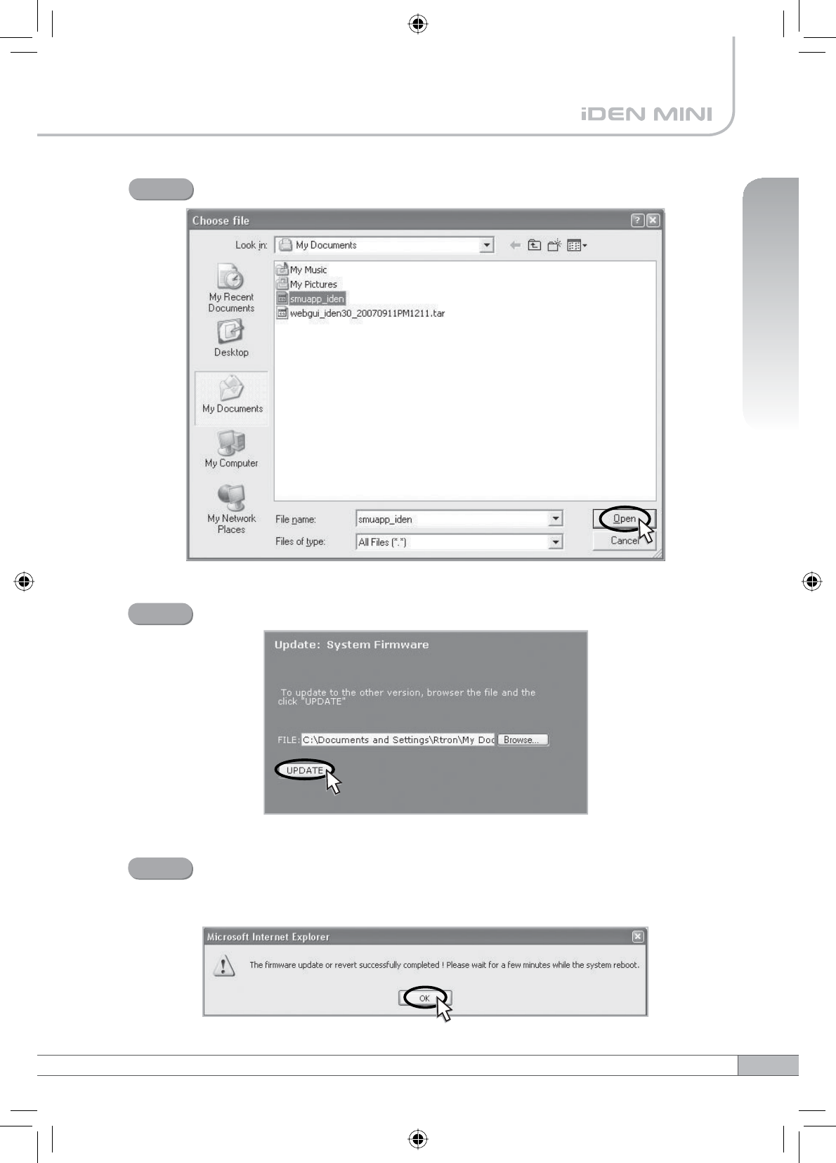
Click Browse.
Step 1
35
User’s Manual
4. Operation
A pop-up window will appear. Select the firmware file and click Open.
Step 2
Click UPDATE.
Step 3
A pop-up window will appear for rebooting after completing all the update
processes.
Click OK to reboot the system.
Step 4
36
4. Operation
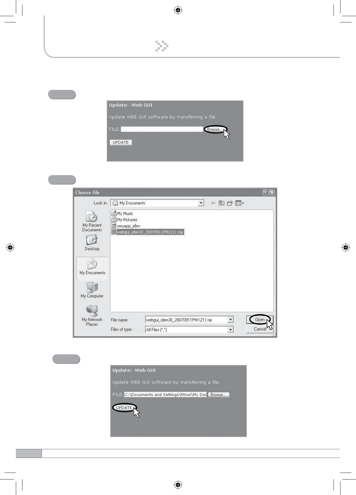
4.5.5.2 Update: Web GUI
Click Browse.
Step 1
A pop-up window will appear. Select the GUI file and click Open.
Step 2
Click UPDATE.
Step 3
37
User’s Manual
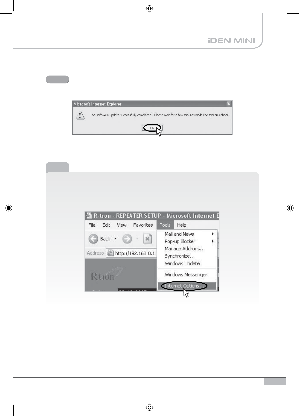
A pop-up window will appear for rebooting after completing all the update
processes.
Click OK to reboot the system.
Step 4
Note
After updating the Web GUI, please delete the Temporary Internet files and
Cookies for the new GUI.
Click Tools and Internet Options….
38
4. Operation
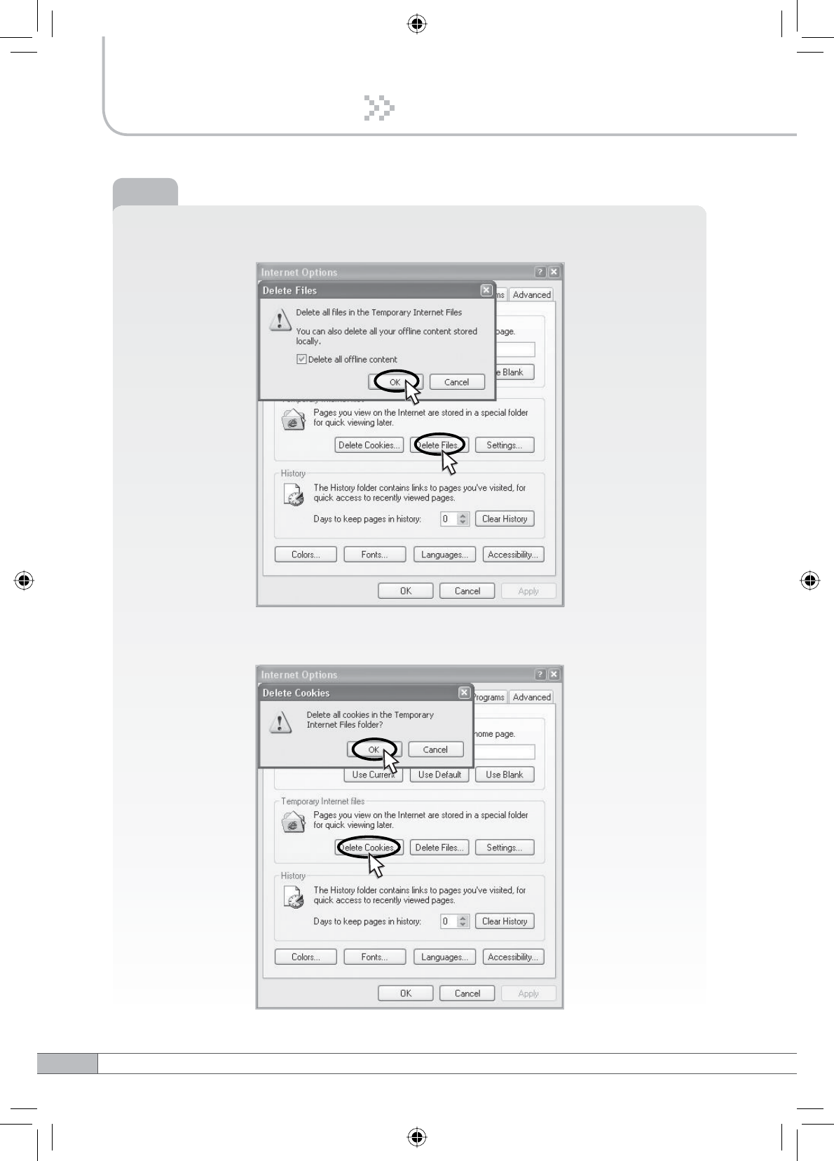
Click Delete Files… and then check Delete all offline content
and click OK.
Note
Click Delete Cookies… and then click OK.
39
User’s Manual
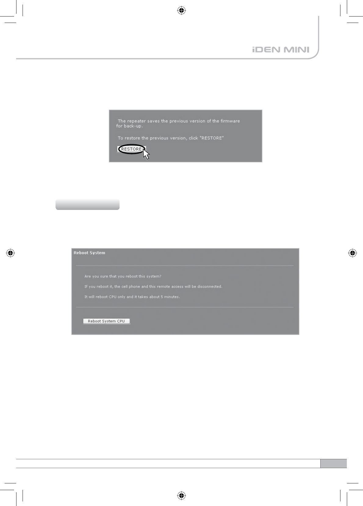
4.5.5.3 Restore
To restore the previous version, click RESTORE.
Click Reboot in the left menu.
In this menu, you can reboot the system.
4.5.6 Reboot
40
4. Operation
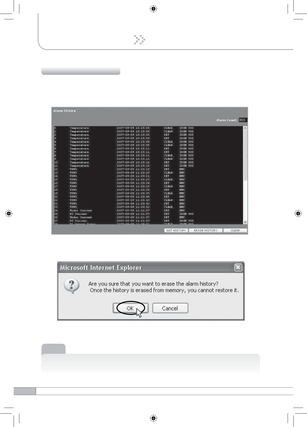
Click Alarm History in the left menu.
Click GET HISTORY, the history list of alarm issued will be displayed.
To erase the alarm history on the memory, click ERASE HISTORY.
A confirmation pop-up window will appear and click OK.
4.5.7 Alarm History
Note
Up to 300 alarm lists can be stored in the memory.
To clear the alarm history on the screen, click CLEAR.
41
User’s Manual
4. Operation
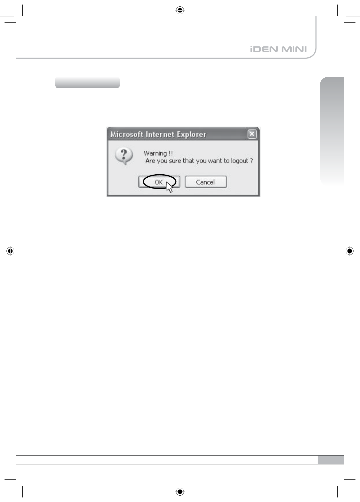
If you want to logout, click Logout in the left menu.
A warning pop-up window will appear and then click OK to logout.
4.5.8 Logout
Problem Solution
Cause
Before contacting your service dealer, please make sure you refer to the following
guide. If the IDEN MINI does not work normally after completing the following
troubleshooting, please contact your local dealer or service center.
42
5. Troubleshooting
No LED On
Cannot
communicate
with the
repeater.
The mobile
phone is not
working well.
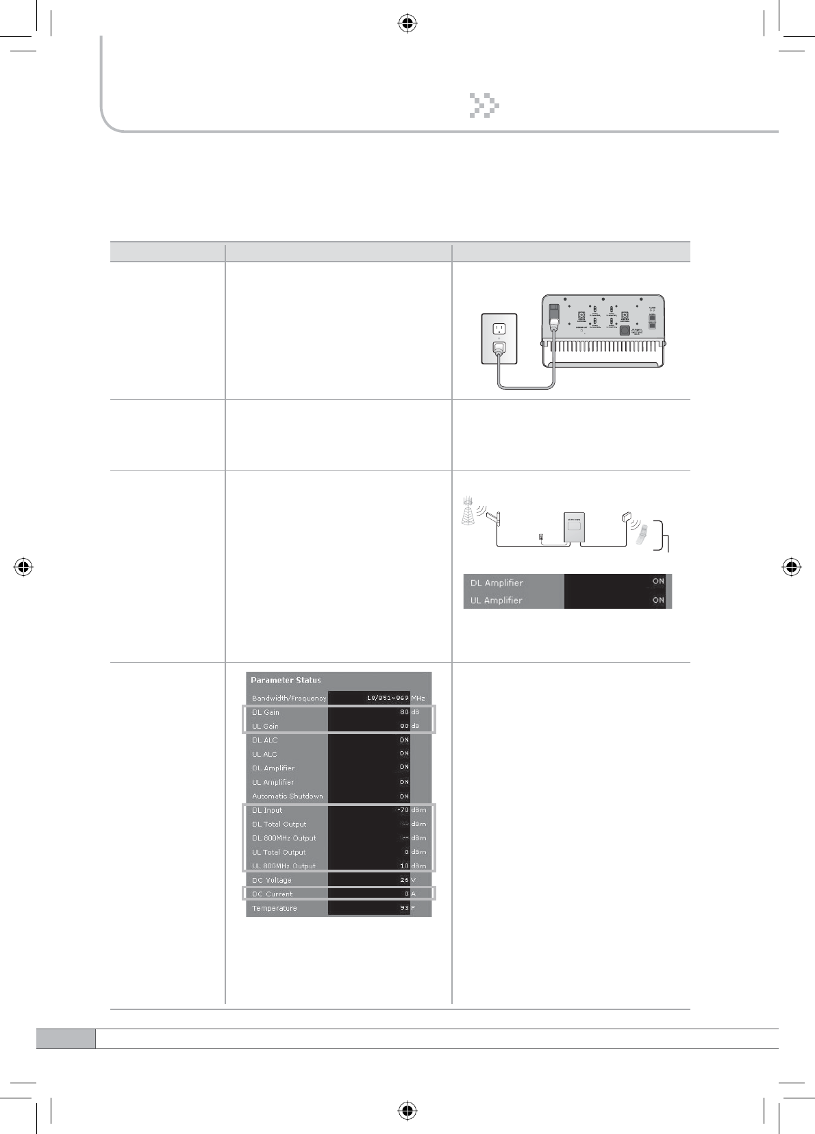
Check the power cord for secure
connection.
Check if the LAN cable is
connected to the repeater and your
computer, or your computer to set
IP address.
Turn on the power.
or
Check if the DL Amplifier and the
UL Amplifier of Parameter Status
are displayed ON.
Turn off the repeater.
Measure the isolation and verify
if the isolation between the donor
antenna and the service antenna is
enough for the repeater. Refer to the
note on page 15.
Oscillation
Repeater
Donor
antenna
Plugged in an
AC outlet
Donor
Base
Station
Service
Mobile Station
Service
antenna
Not working well
1. The values above are changed
randomly under operating of DL
ALC, UL ALC, and ASD.
2. DL Amplifier and UL Amplifier
are on and off iteratively.
Problem Solution
Cause
43
User’s Manual
5. Troubleshooting
Green LED
ĺVWHDG\
Red LED
ĺIODVKLQJ
The red light
turns on.
Check the cable connection to the
service antenna and its VSWR.
Check if the value above is out of
range.
Repeater
Donor
antenna
Plugged in an
AC outlet
Donor
Base
Station
Service
Mobile Station
Service
antenna
Donor antenna connection
ĺ*RRG
Service antenna connection
ĺ%DG
On Site Alarms Lower
-70dBm
0dBm
-
14°F
20V
0A
DL Input Power
DL Output Power
UL Output Power
Temperature
DC Voltage
DC Current
Upper
-30dBm
35dBm
35dBm
176°F
30V
5A
If the Input Power or Output Power
is out of range, please contact
Technical Support.
Download site: www.r-tron.com
Toll Free: 888-31R-TRON
Red & green
LEDs are
flashing
irregularly.
Please contact Technical Support.
Download site: www.r-tron.com
Toll Free: 888-31R-TRON
Malfunction of PSU.
44
6. Specifications
Electrical Specifications
Parameter iDEN 800
DL & UL
Selectable Bandwidth
DL
UL
iDEN 900
In-band BW:18M
In-band BW:7.0M In-band BW:5M
18MHz-
bandwidth
Frequency
Selection
Roll off
Ripple
851~869MHz
850.8~868.8MHz
850.6~868.6MHz
7MHz-
bandwidth
862~869MHz
861.8~868.8MHz
861.6~868.6MHz
5MHz-
bandwidth
935~940MHz
934.8~939.8MHz
934.6~939.6MHz
18MHz-
bandwidth
806~824MHz
805.8~823.8MHz
805.6~823.6MHz
7MHz-
bandwidth
817~824MHz
816.8~823.8MHz
816.6~823.6MHz
5MHz-
bandwidth
896~901MHz
895.8~900.8MHz
895.6~900.6MHz
G%F
@Fedge+ / -500KHz
5dB Max.
12dB Max.
Power supply 110V~125V, 60Hz typical
Operating temperature Û&aÛ&Û)aÛ)
Storage temperature Û&aÛ&Û)aÛ)
Consumption power :DGGLWLRQDO:
3dB (Typical)
Gain 50dB to 80dB
Output Power 30dBm
Delay 8.0µs Max.
VSWR
DL & UL
Input Range -30dBm Max.
DL & UL
DL & UL
DL & UL
DL & UL 1.5Max.
DL & UL G%F
@Fedge+ / -500KHz
UL Noise
Figure
80dB Gain
50dB Gain
45
User’s Manual
6. Specifications
Mechanical Specifications
Parameter Specification
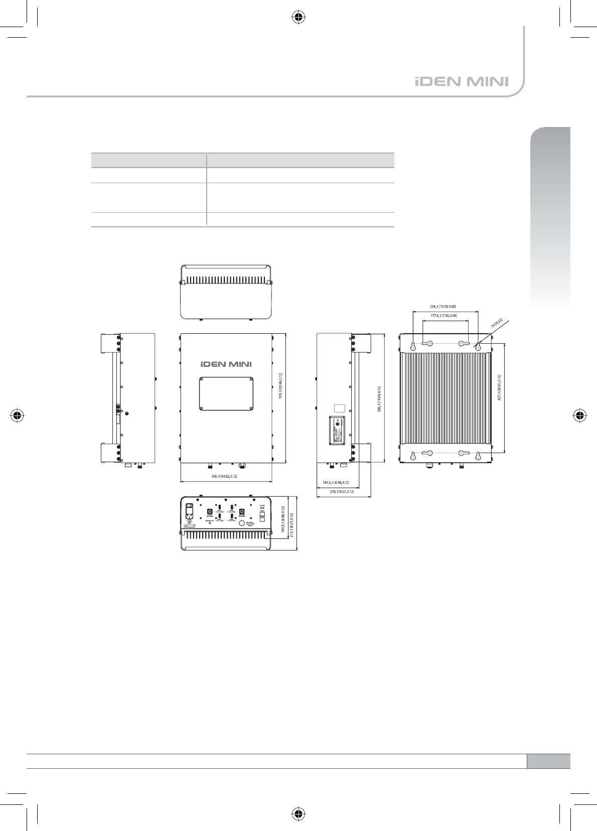
N-female x 2, SMA-female x 5
14.01 X 19.88 X 6.48 (Inch),
356 X 505 X 164.5 (mm)
22.78kg (50.22lbs)
RF connectors
Size
Weight
The specifications are subject to change without any prior notification.
6. Specifications