RESEARCH INSTRUMENTS 670807 RI Witness Embryology Heated Plate User Manual
RESEARCH INSTRUMENTS LTD RI Witness Embryology Heated Plate
UserManual.wiki
>
RESEARCH INSTRUMENTS
>
670807 User Manual
>
User manual
Contents
1.
User manual
2.
Users manual
3.
Installation manual
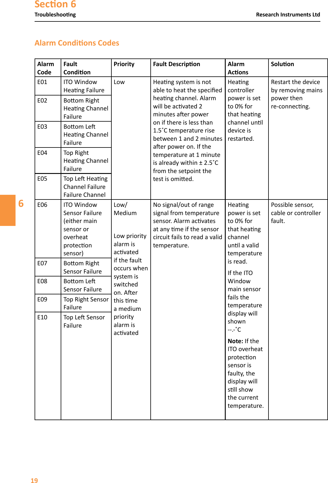
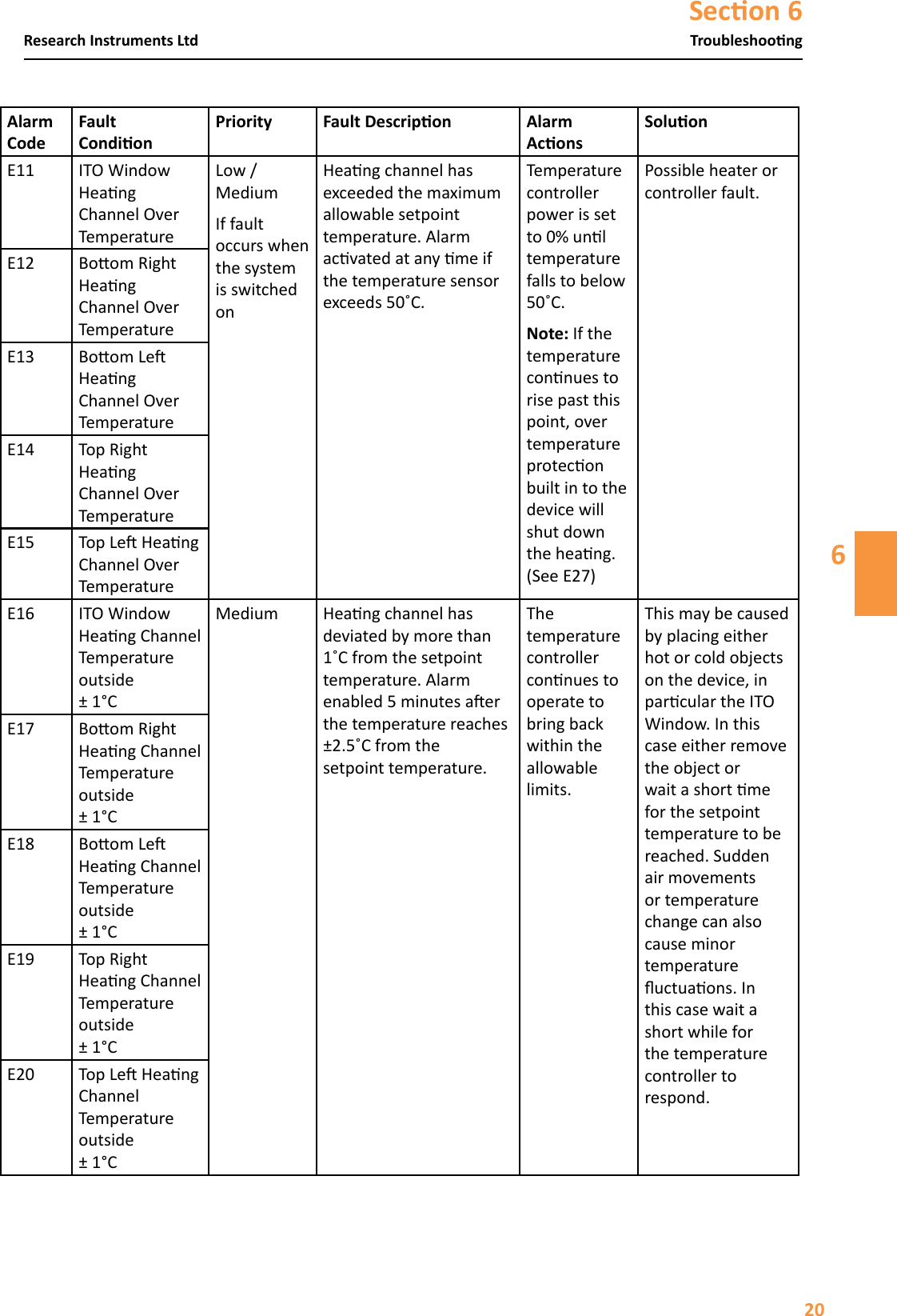
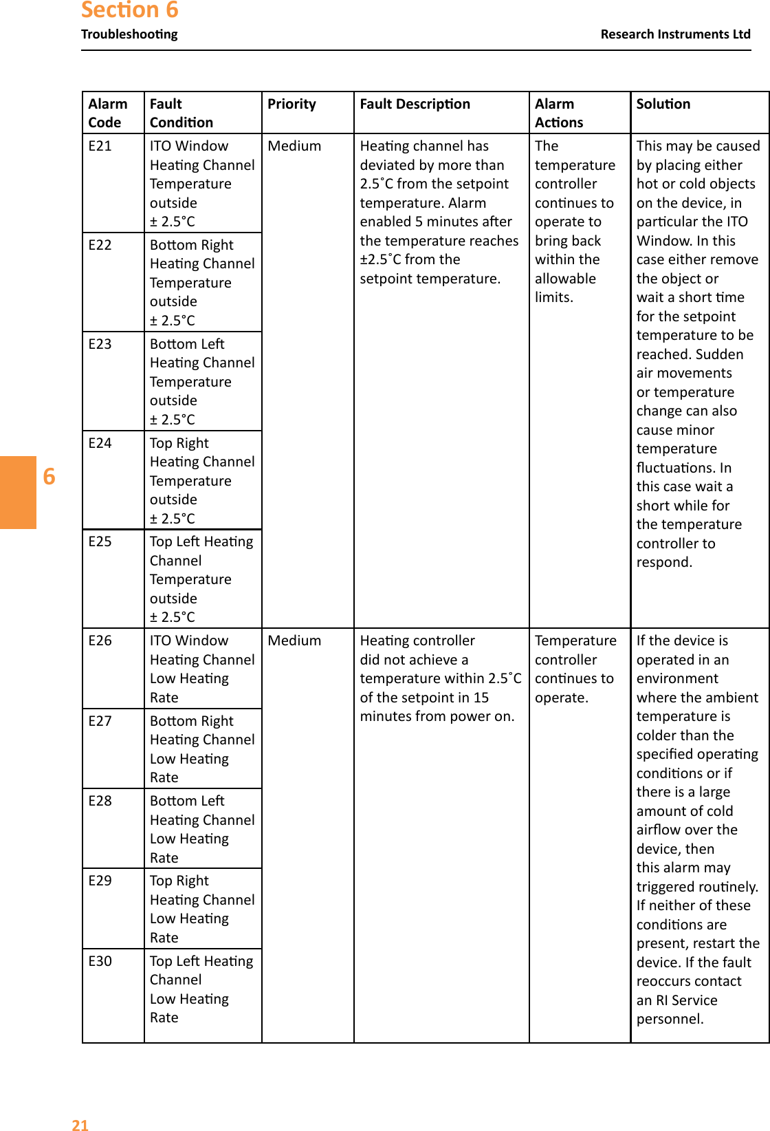
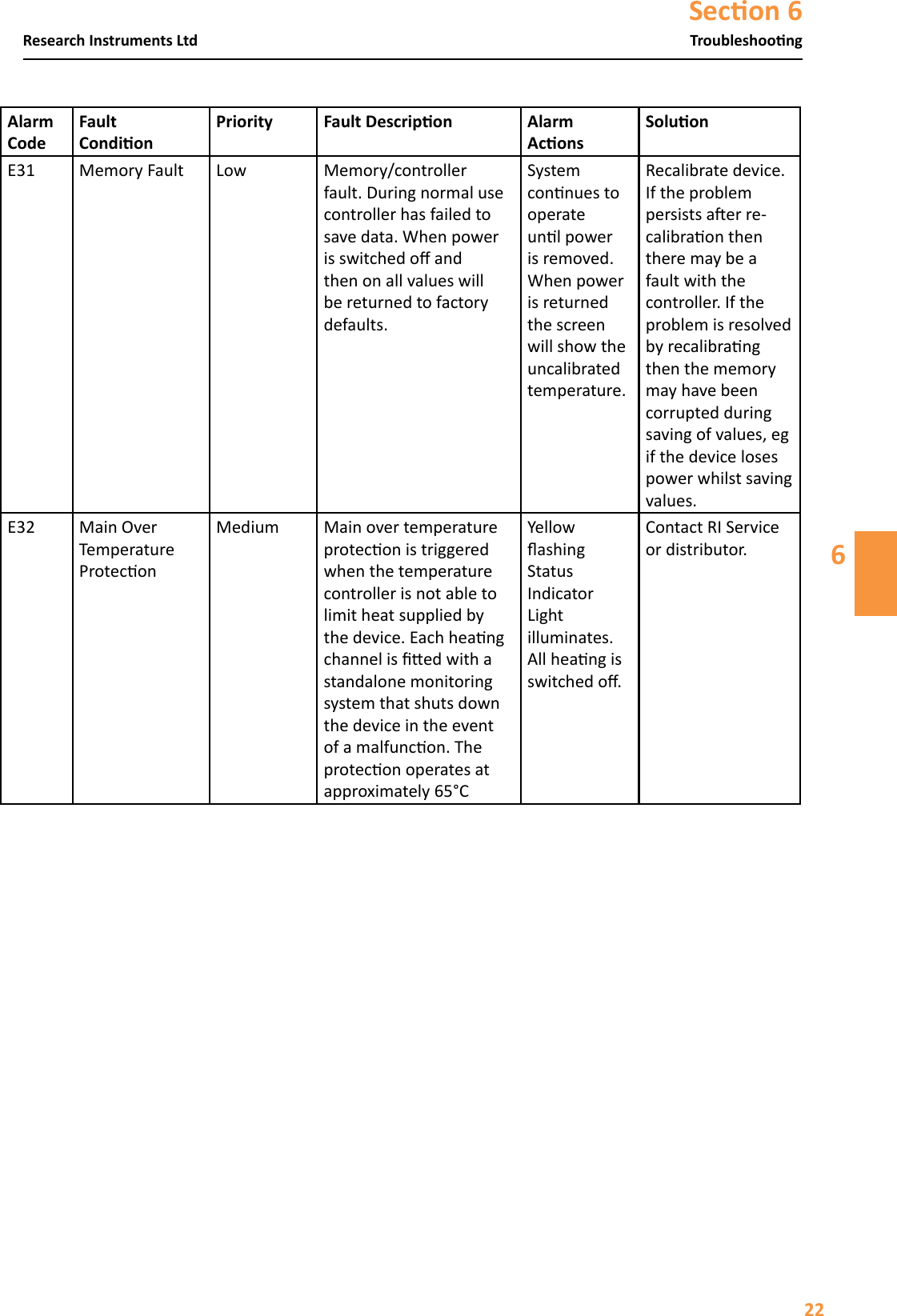
User manual
Navigation menu
Upload a User Manual
Namespaces
Wiki Guide
HTML
PDF
Info
Views
User Manual
Discussion / Help
Navigation
![Secon 36Safety Warnings3 Conducted RF IEC 61000-4-6Radiated RF IEC 61000-4-33 Vrms150 kHz to 80 MHz3 V/m80 MHz to 2.5 GHz3 Vrms3 V/mPortable and mobile RF communicaons equipment should be used no closer to any part of RI Witness, including cables, than the recommended separaon distance calculated from the equaon applicable to the frequency of the transmier. Recommended separaon distanced = [3.5/V 1] √pd = [3.5/V1] √p 80MHz to 800MHzd = [3.5/V1 √p 800MHz to 2.5GHzwhere p is the maximum output power rang of the transmier in was (W) according to the transmier manufacturer and d is the recommended separaon distance in metres (m). Field strengths from xed RF transmiers, as determined by an electromagnec site survey, a should be less than the compliance level in each frequency range. b Interference may occur in the vicinity of equipment marked with the following symbol: At 80 MHz and 800 MHz, the higher frequency range applies. These guidelines may not apply in all situaons. Electromagnec propagaon is aected by absorpon and reecon from structures, objects and people. These guidelines may not apply in all situaons. Electromagnec propagaon is aected by absorpon and reecon from structures, objects and people.a Field strengths from xed transmiers, such as base staons for radio (cellular/cordless) telephones and land mobile radios, amateur radio, AM and FM radio broadcast and TV broadcast cannot be predicted theorecally with accuracy. To assess the electromagnec environment due to xed RF transmiers, an electromagnec site survey should be considered. If the measured eld strength in the locaon in which RI Witness is used exceeds the applicable RF compliance level above, RI Witness should be observed to verify normal operaon. If abnormal performance is observed, addional measures may be necessary, such as re-orienng or relocang RI Witness.b Over the frequency range 150 kHz to 80 MHz, eld strengths should be less than [V] V/m.](https://usermanual.wiki/RESEARCH-INSTRUMENTS/670807.User-manual/User-Guide-3080949-Page-9.png)