RESEARCH INSTRUMENTS 670807 RlWITNESS EMBRYOLOGY HEATED PLATE User Manual Users manual
RESEARCH INSTRUMENTS LTD RlWITNESS EMBRYOLOGY HEATED PLATE Users manual
UserManual.wiki
>
RESEARCH INSTRUMENTS
>
670807 User Manual
>
Users manual
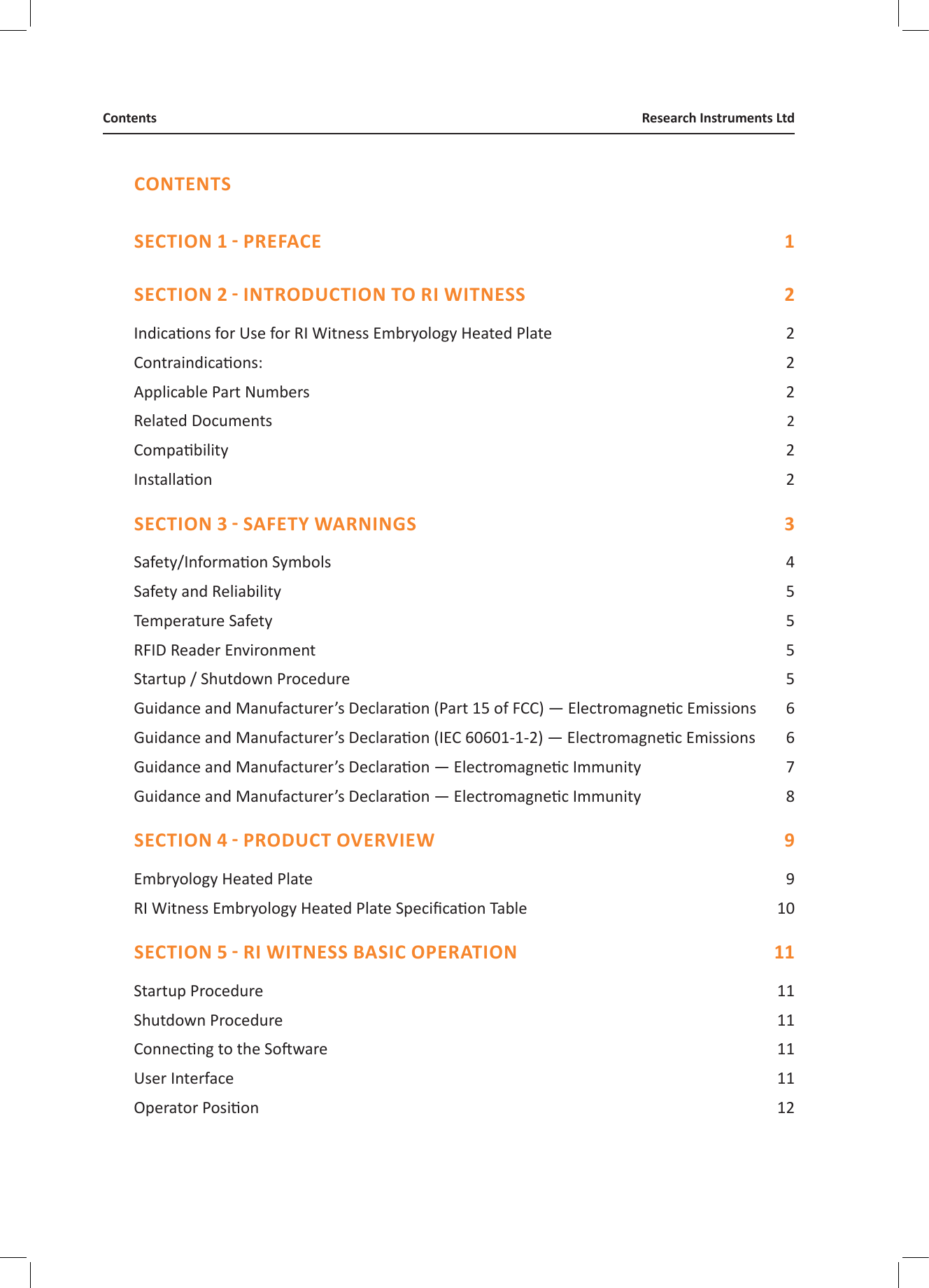
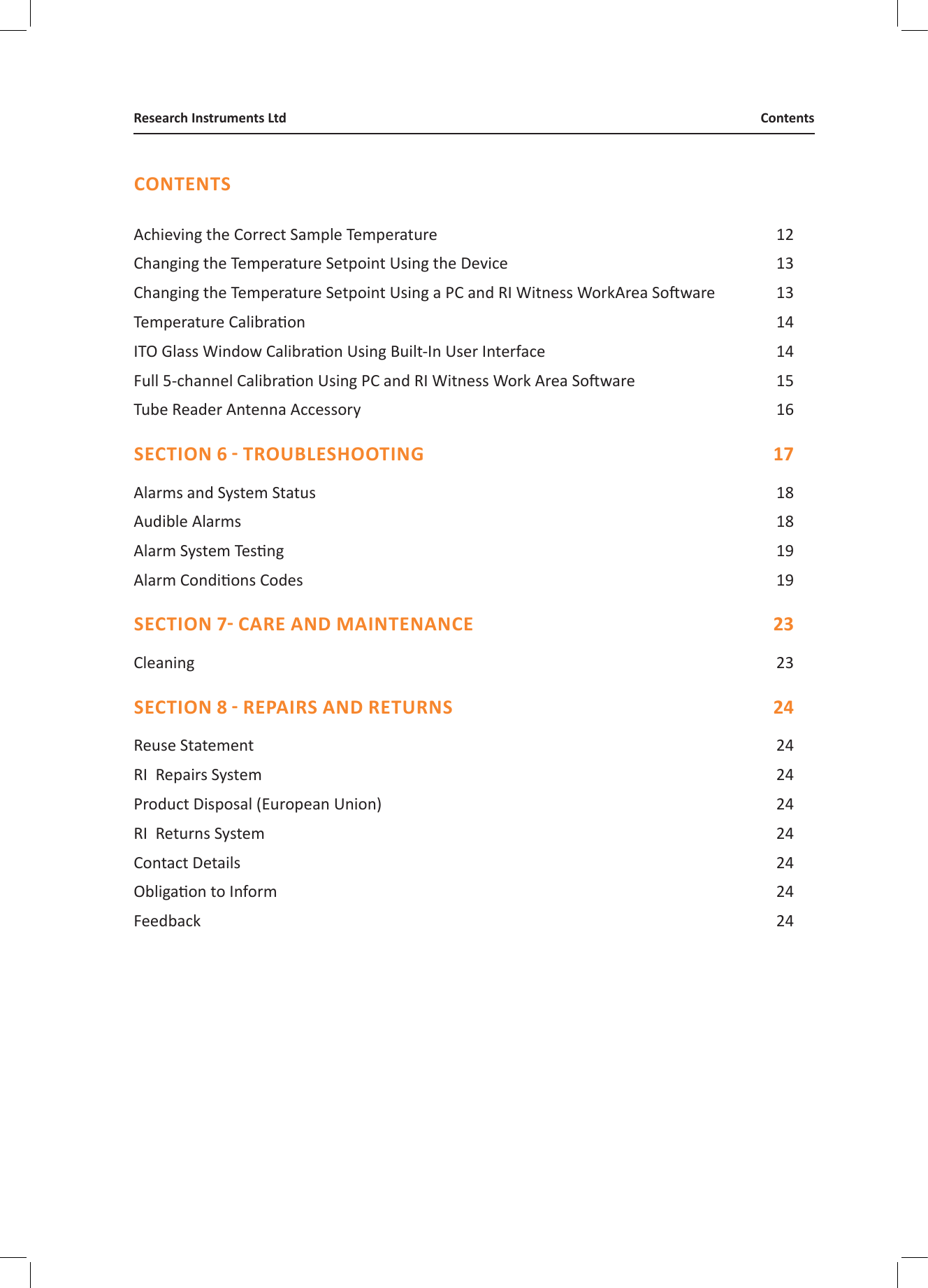
Contents
1.
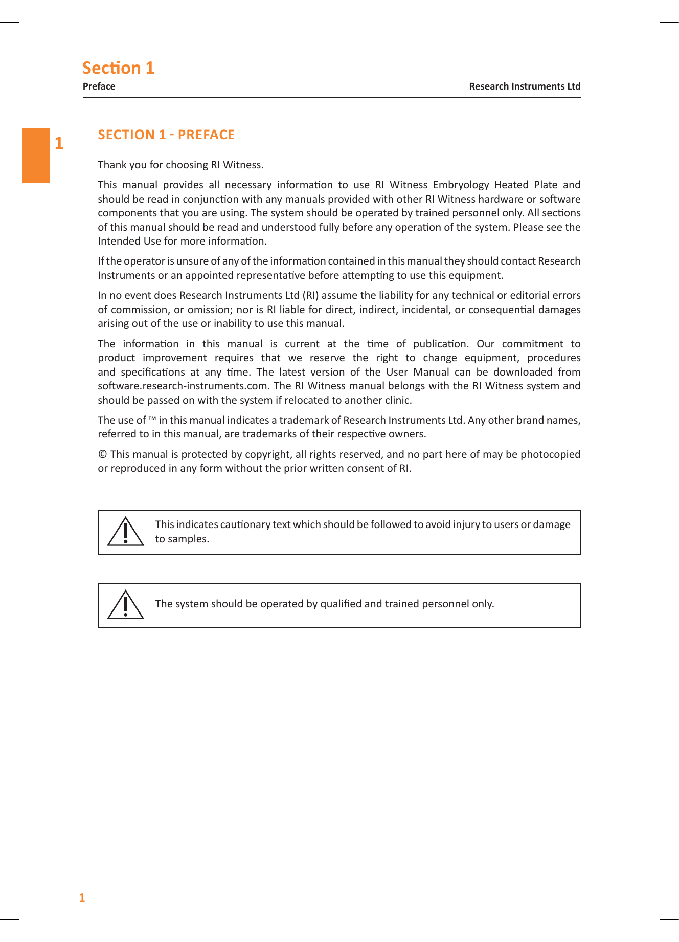
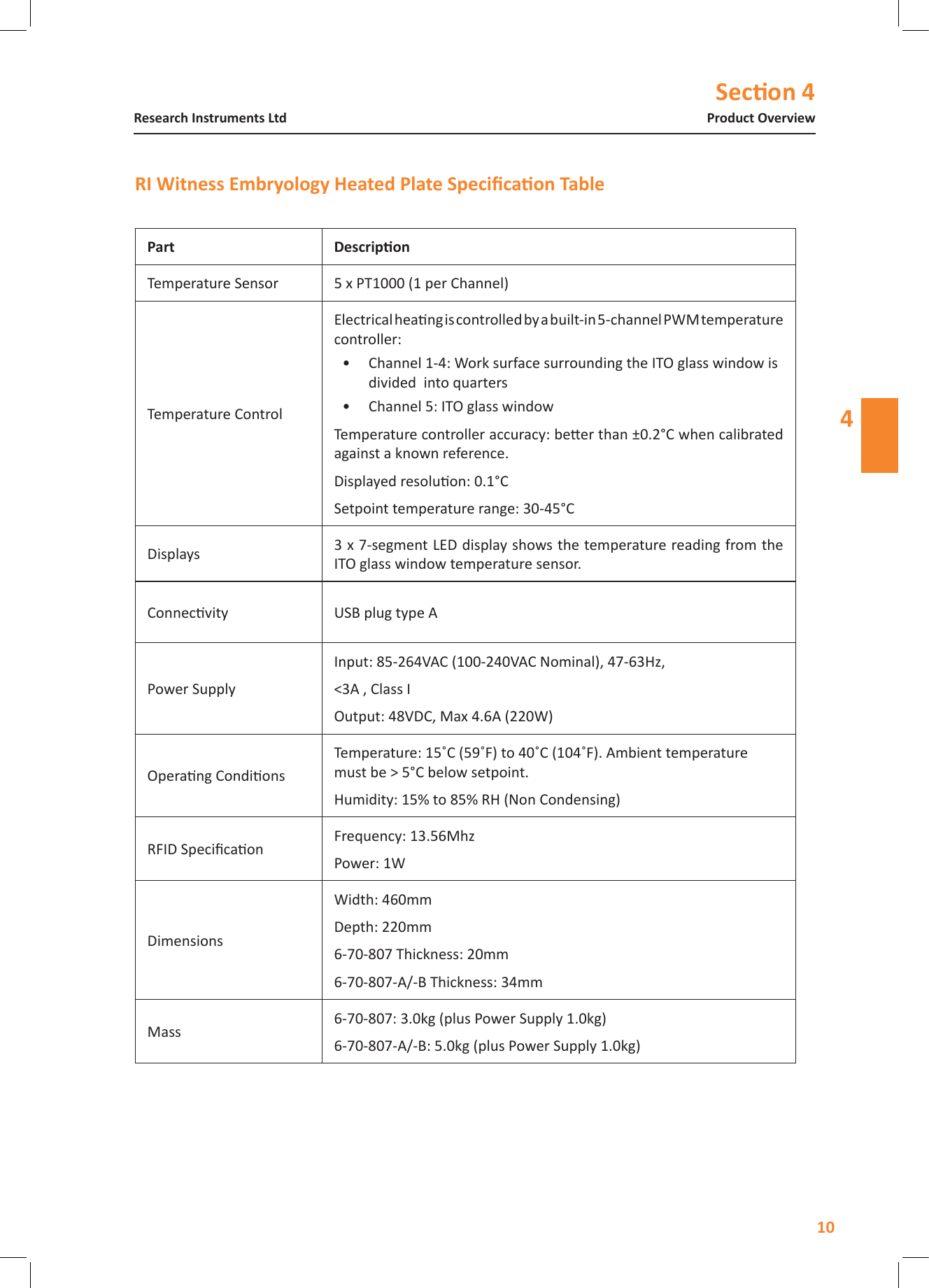
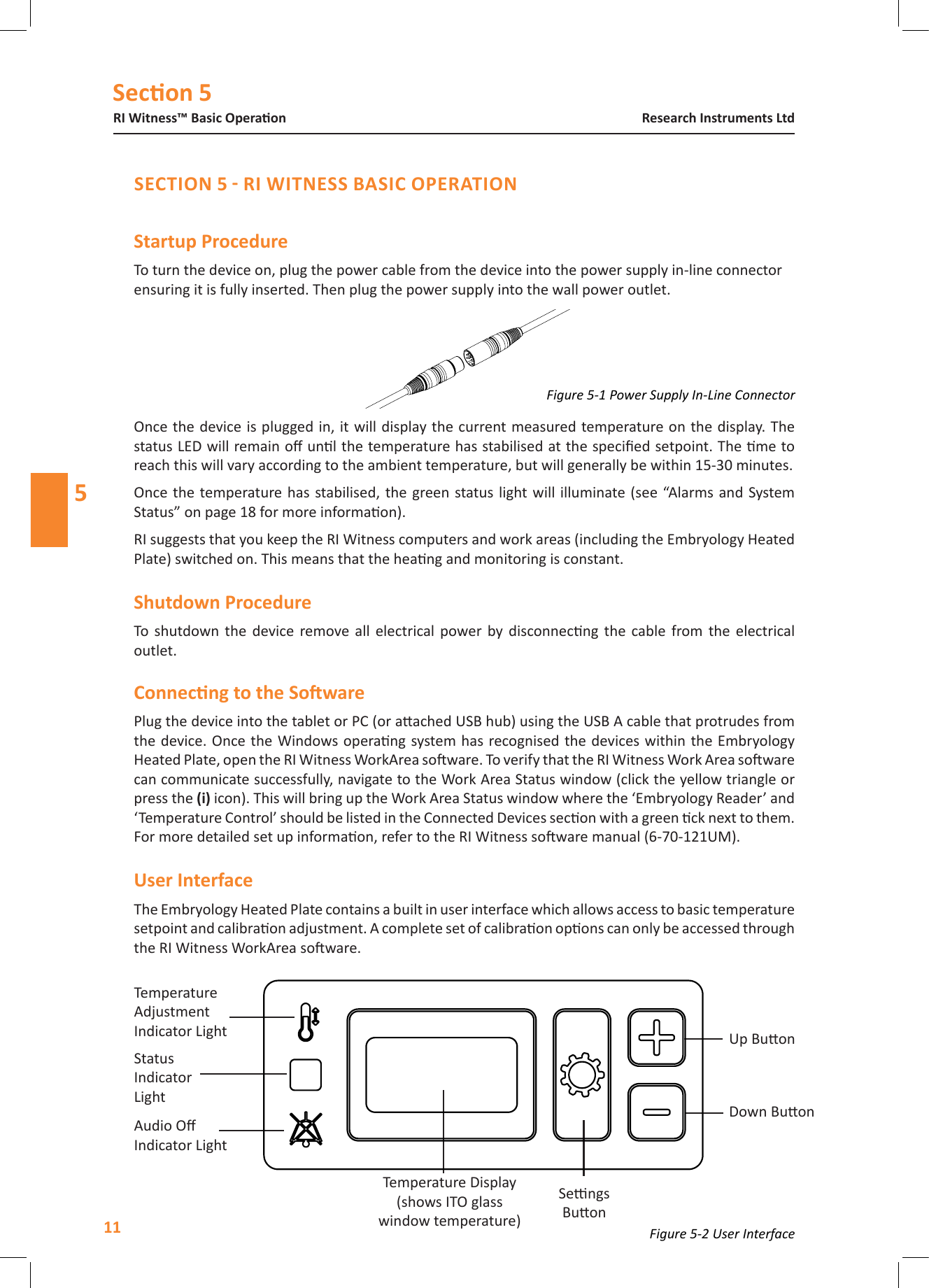
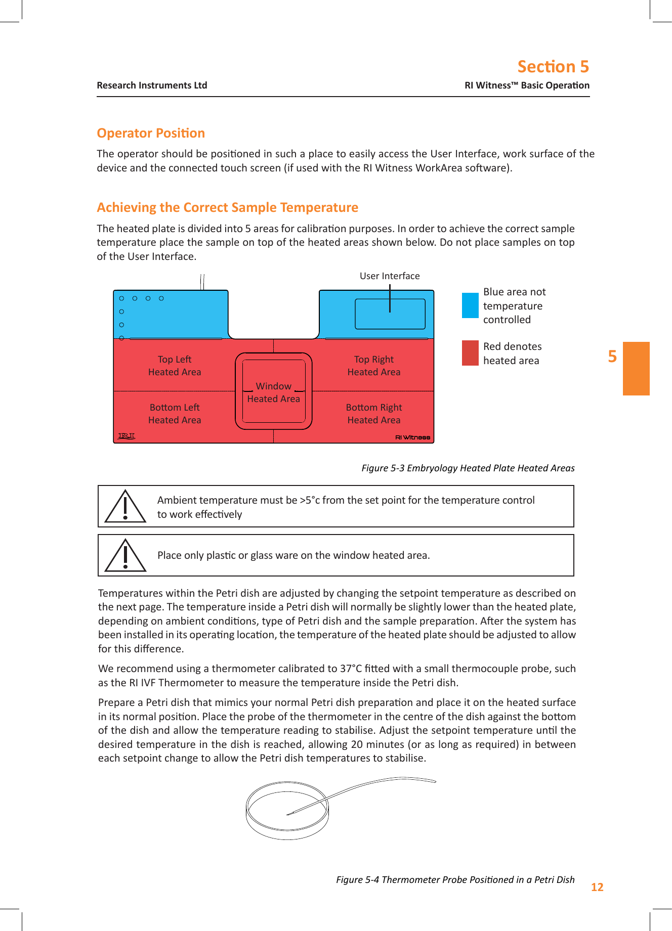
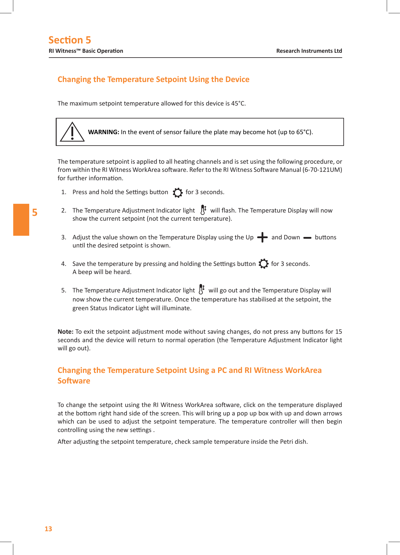
User manual
2.
Users manual
3.
Installation manual
Users manual
Navigation menu
Upload a User Manual
Namespaces
Wiki Guide
HTML
PDF
Info
Views
User Manual
Discussion / Help
Navigation