RESEARCH INSTRUMENTS 670807 RlWITNESS EMBRYOLOGY HEATED PLATE User Manual Users manual
RESEARCH INSTRUMENTS LTD RlWITNESS EMBRYOLOGY HEATED PLATE Users manual
Contents
- 1. User manual
- 2. Users manual
- 3. Installation manual
Users manual

User Manual
RI WITNESS™
Embryology Heated Plate
+44 (0) 1737 243869 | customerservice@origio.com | origio.com
Research Instruments Ltd, Bickland Industrial Park, Falmouth, Cornwall TR11 4TA, UK
Document 6-70-807UM | DRF 3728 | Issue 5 | 1 December 2017
0120
only

CONTENTS
Indicaons for Use for RI Witness Embryology Heated Plate 2
Contraindicaons: 2
Applicable Part Numbers 2
Related Documents 2
Compability 2
Installaon 2
Safety/Informaon Symbols 4
Safety and Reliability 5
Temperature Safety 5
RFID Reader Environment 5
Startup / Shutdown Procedure 5
Guidance and Manufacturer’s Declaraon (Part 15 of FCC) — Electromagnec Emissions 6
Guidance and Manufacturer’s Declaraon (IEC 60601-1-2) — Electromagnec Emissions 6
Guidance and Manufacturer’s Declaraon — Electromagnec Immunity 7
Guidance and Manufacturer’s Declaraon — Electromagnec Immunity 8
Embryology Heated Plate 9
RI Witness Embryology Heated Plate Specicaon Table 10
Startup Procedure 11
Shutdown Procedure 11
Connecng to the Soware 11
User Interface 11
Operator Posion 12
Research Instruments LtdContents

Achieving the Correct Sample Temperature 12
Changing the Temperature Setpoint Using the Device 13
Changing the Temperature Setpoint Using a PC and RI Witness WorkArea Soware 13
Temperature Calibraon 14
ITO Glass Window Calibraon Using Built-In User Interface 14
Full 5-channel Calibraon Using PC and RI Witness Work Area Soware 15
Tube Reader Antenna Accessory 16
Alarms and System Status 18
Audible Alarms 18
Alarm System Tesng 19
Alarm Condions Codes 19
Cleaning 23
Reuse Statement 24
RI Repairs System 24
Product Disposal (European Union) 24
RI Returns System 24
Contact Details 24
Obligaon to Inform 24
Feedback 24
CONTENTS
ContentsResearch Instruments Ltd
Secon 1
1
1
Research Instruments Ltd
Preface
Thank you for choosing RI Witness.
This manual provides all necessary informaon to use RI Witness Embryology Heated Plate and
should be read in conjuncon with any manuals provided with other RI Witness hardware or soware
components that you are using. The system should be operated by trained personnel only. All secons
of this manual should be read and understood fully before any operaon of the system. Please see the
Intended Use for more informaon.
If the operator is unsure of any of the informaon contained in this manual they should contact Research
Instruments or an appointed representave before aempng to use this equipment.
In no event does Research Instruments Ltd (RI) assume the liability for any technical or editorial errors
of commission, or omission; nor is RI liable for direct, indirect, incidental, or consequenal damages
arising out of the use or inability to use this manual.
The informaon in this manual is current at the me of publicaon. Our commitment to
product improvement requires that we reserve the right to change equipment, procedures
and specicaons at any me. The latest version of the User Manual can be downloaded from
soware.research-instruments.com. The RI Witness manual belongs with the RI Witness system and
should be passed on with the system if relocated to another clinic.
The use of ™ in this manual indicates a trademark of Research Instruments Ltd. Any other brand names,
referred to in this manual, are trademarks of their respecve owners.
© This manual is protected by copyright, all rights reserved, and no part here of may be photocopied
or reproduced in any form without the prior wrien consent of RI.
This indicates cauonary text which should be followed to avoid injury to users or damage
to samples.
The system should be operated by qualied and trained personnel only.
Secon 2
2
Introducon
Research Instruments Ltd
2
To maintain the temperature of human reproducve ssue such as oocytes and embryos through an
assisted reproducon (AR) cycle.
This device is not intended to be exposed to known sources of electromagnec interference (EMI)
with medical devices such as diathermy, CT, MRI, RFID (except other RI Witness RFID components) and
electromagnec security systems, eg metal detectors and electronic arcle surveillance systems.
Applicable indicaons for use are subject to the regulaons of the country into which the device is sold.
Availability of RI Witness for clinical use is dependent on the regulatory approval status of RI Witness
within the country the device is intended to be sold into.
6-7-121UM RI Witness WorkArea Soware Manual
6-7-122UM RI Witness Manager Soware Manual
RI Witness is used in conjuncon with the following:
• Essenal medical devices, eg dishes and tubes, maybe AR or non-AR specic.
• Non-essenal medical devices, eg safety cabinets, incubators, micromanipulators, lasers.
• Non medical devices (general laboratory equipment), eg work benches, microscopes, PCs.
This device has RFID reader capability. If it is the intenon that it be employed in a clinical lab, we
recommend its use alongside other medical devices and that the performance of these medical devices
be monitored for potenal eects of EMI disturbances, and reported when appropriate.
Installaons of the RI Witness Embryology Heated plate should be carried out by a RI technician or
other RI authorised personnel. Incorrect installaon could result in overall poor performance.
6-70-807* RI Witness Embryology Heated Plate
6-70-809 RI Witness Tube Reader
* 6-70-807 can be supplied in several conguraons depending on the required mounng type, eg ush
ed or sit on top.
0120
only
Secon 3
Safety Warnings
3
Research Instruments Ltd
3
disassemble or modify any part of the RI Witness Embryology Heated plate, or
substute any component for any other. Doing so may result in damage to samples. This
voids the warranty and/or service contract.
To avoid the risk of electric shock, this equipment must only be connected
to a supply mains with protecve earth.
use the power cable and power supply adaptor supplied with the system.
The cable to the power supply is the ‘disconnect device’ for this equipment. To remove all
electrical power from this product, disconnect the power cable from the electrical outlet.
Equipment should be posioned so as to allow easy access to the power cable. The appliance
coupler or mains plug is used as the disconnect and must remain readily operable.
Not to be used in a paent environment.
The system should be operated by qualied and trained personnel only.
This symbol indicates cauonary text which should be followed to avoid injury to users
or damage to samples.
Refer to Guidance and Manufacturer’s Declaraon Tables in this secon of the
User Manual for guidance on the environment suitable for this device.
Use of this equipment adjacent to or stacked with other equipment should
be avoided because it could result in improper operaon. If such use is necessary, this
equipment and the other equipment should be observed to verify that they are operang
normally.
The temperature of the plate should not be more than 1.5ºC from the
displayed temperature at any me. A temperature of more than 1.5ºC will cause the
temperature inside the dish to change more rapidly and samples are at risk of over-
heang. In this instance samples should be removed from the plate immediately.
We recommend the plate temperature be monitored periodically using a calibrated
thermocouple thermometer.
There are no replaceable parts supplied with this device. Should any parts
need to be replaced, contact RI or your distributor.
Use of accessories, transducers and cables other than those specied or
provided by the manufacturer of this equipment could result in increased electromagnec
emissions or decreased electromagnec immunity of this equipment and result in
improper operaon.
Portable RF communicaons equipment (including peripherals such as antenna
cables and external antennas) should be used no closer than 30 cm (12 inches) to any
part of the Embryology Heated Plate, including cables specied by the manufacturer.
Otherwise, degradaon of the performance of this equipment could result.
Secon 3
4
Safety Warnings
Research Instruments Ltd
3
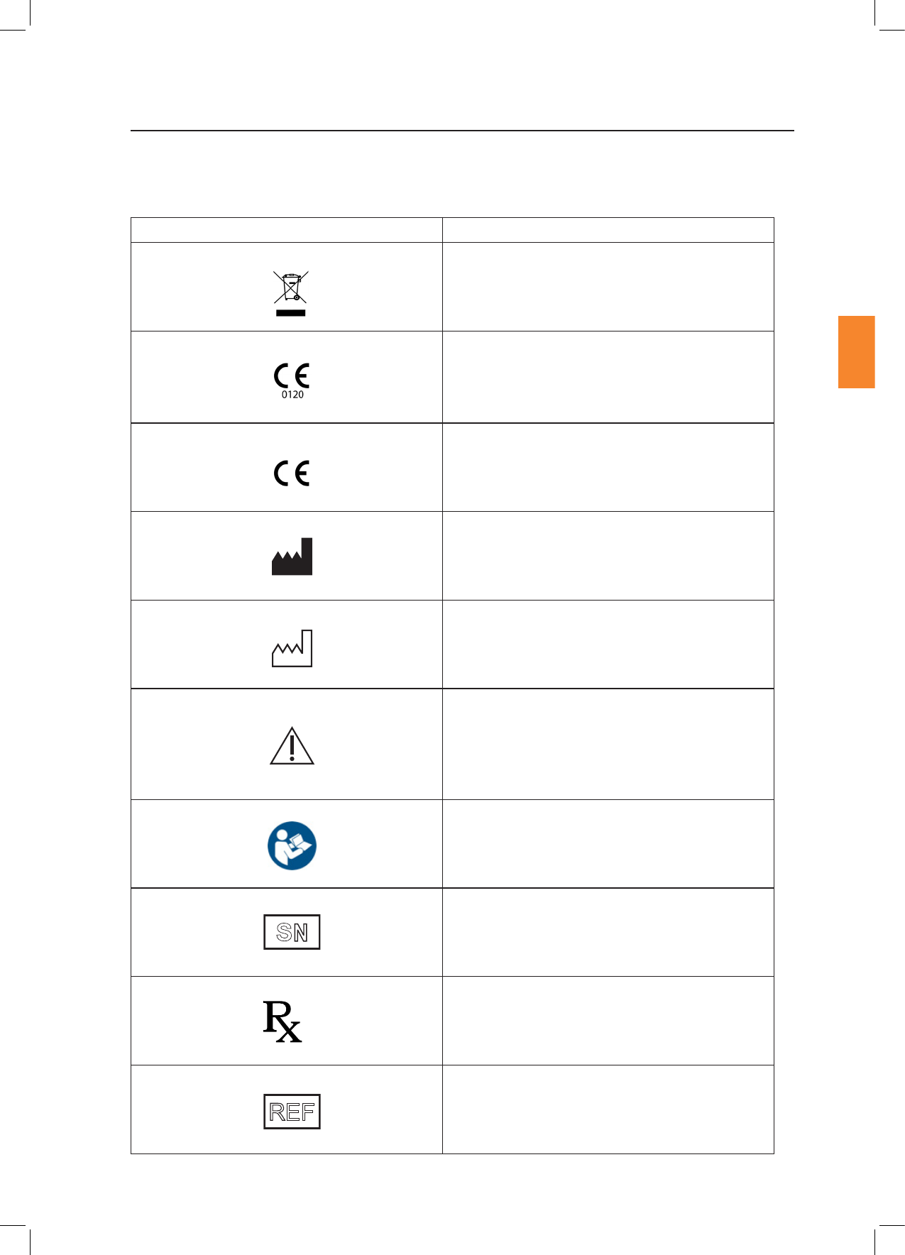
Do not dispose of product with normal waste.
In accordance with Annex II of the European
Medical Device Direcve 93/42/EEC, as amended
by Direcve 2007/47/EC under the supervision of
noed body No.0120, SGS, UK Ltd.
In accordance with the European Direcve for
R&TTE, Direcve 1999/5/EC.
Indicates the medical device manufacturer.
Indicates the date of manufacture.
Indicates the need for the user to consult the
instrucons for use for important cauonary
informaon such as warnings and precauons that
cannot, for a variety of reasons, be presented on
the medical device itself.
Consult instrucons for use.
The ve digit number is a unique idener assigned
to the product.
Cauon: US Federal law restricts this device for
sale to or on the order of a licensed healthcare
praconer.
Indicates the reference number.
S
N
Only
REF
Secon 3
Safety Warnings
5
Research Instruments Ltd
3
Please read this manual carefully and follow the instrucons to ensure that the system will work safely
and reliably.
Safety is the responsibility of the laboratory. Risk assessment and working pracces should comply with
local regulatory policies.
A warning triangle will be displayed on the work area touch screen and the status LED on the device
user interface will display a yellow status alarm if the currently selected temperature cannot
be maintained.
Gently place your hand on the heated surface to verify that the temperature is appropriate for use.
As with all heang systems, it is advisable to perform a periodic check of temperatures using a calibrated
thermocouple thermometer.
An RI Witness system uses Radio Frequency Idencaon (RFID) readers to monitor a work area.
Readers detect RFID tagged containers that are placed in the work area.
The performance of RFID tag detecon may be compromised by proximity of metal objects or electrical
equipment
Do not place metal objects near reader.
Do not place electrical equipment near reader.
RI Witness hardware may be damaged by incorrect startup and shutdown procedures.
“Secon 5 - RI Witness Basic Operaon” on page 11 describes the recommended startup and
shutdown procedure for the RI Witness Embryology Heated Plate.

Secon 3
6
Safety Warnings
Research Instruments Ltd
3
RI Witness is intended for use in the electromagnec environment specied below. The customer or
the user of RI Witness should ensure that it is used in such an environment.
Emissions test Compliance
RF emissions
CISPR 11 Group 2
RI Witness must emit electromagnec energy in
order to perform its intended funcon. Nearby
electronic equipment may be aected.
RF emissions
CISPR 11 Class B
RI Witness is suitable for use in all establishments
other than domesc and those directly connected
to the public low-voltage power supply network
that supplies buildings used for domesc
purposes.
Harmonic emissions
EN 61000-3-2
Class A
Voltage uctuaons/
icker emissions
EN 61000-3-3
Complies
This equipment has been tested and found to comply with the limits for a Class A digital device,
pursuant to part 15 of the Federal Communicaons Commision (FCC) Rules. These limits are designed
to provide reasonable protecon against harmful interference when the equipment is operated in a
commercial environment. This equipment generates, uses, and can radiate radio frequency energy and,
if not installed and used in accordance with the instrucon manual, may cause harmful interference
to radio communicaons. Operaon of this equipment in a residenal area is likely to cause harmful
interference in which case the user will be required to correct the interference at their own expense.
This device complies with Industry Canada’s licence-exempt RSSs. Operaon is subject to the
following two condions:
1. This device may not cause interference.
2. This device must accept any interference, including interference that may cause undesired operaon
of the device.

Secon 3
Safety Warnings
Research Instruments Ltd
3
Electrostac discharge
(ESD)
IEC 61000-4-2
± 8 kV contact
± 15 kV air
± 8 kV contact
± 15 kV air
Floors should be wood,
concrete or ceramic le.
If oors are covered
with synthec material,
the relave humidity
should be at least 30%.
Electrical fast transient/
burst
IEC 61000-4-4
± 2 kV for power supply
lines
± 1 kV for input/output
lines
± 2 kV for power
supply lines
± 1 kV for input/
output Lines
Mains power quality
should be that of a
typical commercial or
hospital environment.
Surge
IEC 61000-4-5
± 1 kV line(s) to line(s)
± 2 kV line(s) to earth
± 1 kV dierenal
Mode
± 2 kV common mode
Mains power quality
should be that of a
typical commercial or
hospital environment.
Voltage dips, short
interrupons and voltage
variaons on power
supply input lines
IEC 61000-4-11
<5 % UT
(>95 % dip in UT ) for
0.5 cycle
40 % UT
(60 % dip in UT) for 5
cycles
70 % UT
(30 % dip in UT) for 25
cycles
<5 % UT
(>95 % dip in UT)
for 5s
<5 % UT
(>95 % dip in UT ) for
0.5 cycle
40 % UT
(60 % dip in UT) for 5
cycles
70 % UT
(30 % dip in UT) for 25
cycles
<5 % UT
(>95 % dip in UT)
for 5s
Mains power quality
should be that of a
typical commercial or
hospital environment.
If the user of RI Witness
requires connued
operaon during power
mains interrupons, it
is recommended that
RI Witness be powered
from an uninterrupble
power supply or a
baery.
Power frequency
(50/60 Hz)
magnec eld
IEC 61000-4-8
30A/M30A/MPower frequency
magnec elds
should be at levels
characterisc of a
typical locaon in a
typical commercial or
hospital environment.
NoteUT is the a.c. mains voltage prior to applicaon of the test level.
Compliance with the emissions requirements of CISPR 22 Class A requires the following warning:
“This is a class A product. In a domesc environment this product may cause radio interference in
which case the user may be required to take adequate measures.”

Secon 3
8
Safety Warnings
Research Instruments Ltd
3
Compliance
Conducted RF IEC
61000-4-6
Radiated RF IEC
61000-4-3
3 Vrms
150 kHz to 80 MHz
3 V/m
80 MHz to 2.5 GHz
3 Vrms
3 V/m
Portable RF communicaons equipment
(including peripherals such as antenna
cables and external antennas) should be
used no closer than 30 cm (12 inches)
to any part of the Embryology Heated
Plate, including cables specied by the
manufacturer. Otherwise, degradaon of
the performance of this equipment could
result.
Secon 4
Product Overview
Research Instruments Ltd
4
RI Witness is a system which operates within an assisted reproducon (AR) clinic seng and provides
a method of idenfying human samples throughout an AR cycle (from egg and sperm collecon to
embryo transfer). The system is intended to minimise the risks associated with tradional/manual
double-checking and provides the essenal controls necessary to ensure eggs, sperm and embryos are
correctly matched and treated during the AR process.
The RI Witness system comprises hardware, rmware and soware components, which can be
congured depending on the treatment acvies, number of AR cycles conducted, size and layout of
the AR clinic.
RFID (radio frequency idencaon) technology provides the means of idenfying the containers
(dishes, tubes) in which eggs, sperm and embryos are transferred and stored. The containers are
labelled by a clinician with a special RFID tag which has been assigned a unique idener. The unique
idener is linked to a paent/couple (specic parentage).
As samples are processed as part of an AR cycle, RFID readers (both heated and non-heated) read the
tags on the container and their identy and status is conrmed on-screen. If containers containing
samples of incompable origin come into contact at any stage of this process, the system acvates an
alarm and prompts the clinician to respond.
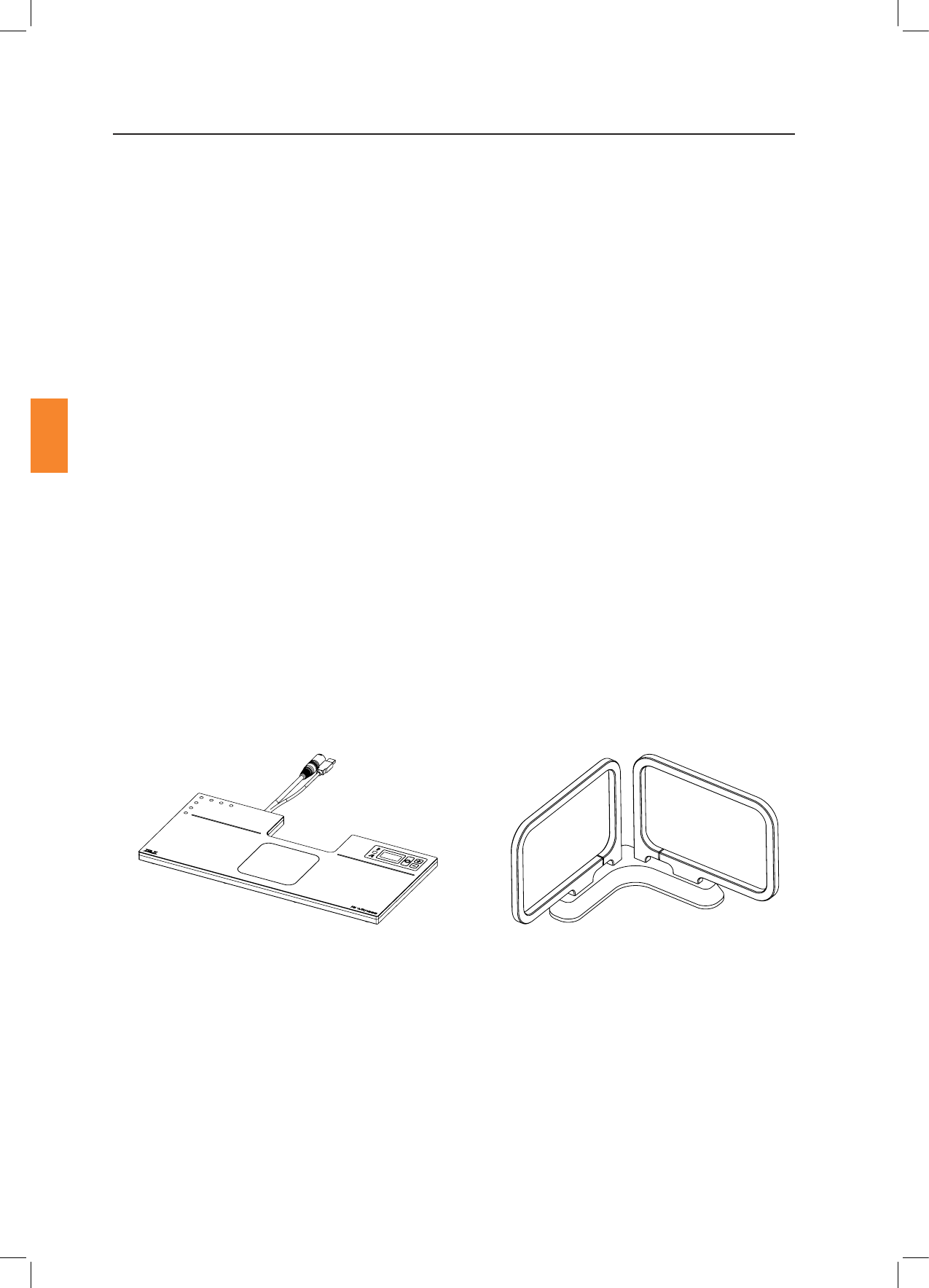
This manual is specically for the Embryology Heated Plate (and associated Tube Reader accessory) in
both its ush ed and sit on top conguraon.
Other devices in the RI Witness range have their own manuals, as does the soware.
Figure 4-1 Sit on Top Heated Reader Figure 4-2 Tube Reader Accessory

Secon 4
Product Overview
Research Instruments Ltd
4
Part
Temperature Sensor 5 x PT1000 (1 per Channel)
Temperature Control
Electrical heang is controlled by a built-in 5-channel PWM temperature
controller:
• Channel 1-4: Work surface surrounding the ITO glass window is
divided into quarters
• Channel 5: ITO glass window
Temperature controller accuracy: beer than ±0.2°C when calibrated
against a known reference.
Displayed resoluon: 0.1°C
Setpoint temperature range: 30-45°C
Displays 3 x 7-segment LED display shows the temperature reading from the
ITO glass window temperature sensor.
Connecvity USB plug type A
Power Supply
Input: 85-264VAC (100-240VAC Nominal), 47-63Hz,
<3A , Class I
Output: 48VDC, Max 4.6A (220W)
Operang Condions
Temperature: 15˚C (59˚F) to 40˚C (104˚F). Ambient temperature
must be > 5°C below setpoint.
Humidity: 15% to 85% RH (Non Condensing)
RFID Specicaon Frequency: 13.56Mhz
Power: 1W
Dimensions
Width: 460mm
Depth: 220mm
6-70-807 Thickness: 20mm
6-70-807-A/-B Thickness: 34mm
Mass 6-70-807: 3.0kg (plus Power Supply 1.0kg)
6-70-807-A/-B: 5.0kg (plus Power Supply 1.0kg)
Secon 5
RI Witness™ Basic Operaon
11
Research Instruments Ltd
5
Startup Procedure
To turn the device on, plug the power cable from the device into the power supply in-line connector
ensuring it is fully inserted. Then plug the power supply into the wall power outlet.
Once the device is plugged in, it will display the current measured temperature on the display. The
status LED will remain o unl the temperature has stabilised at the specied setpoint. The me to
reach this will vary according to the ambient temperature, but will generally be within 15-30 minutes.
Once the temperature has stabilised, the green status light will illuminate (see “Alarms and System
Status” on page 18 for more informaon).
RI suggests that you keep the RI Witness computers and work areas (including the Embryology Heated
Plate) switched on. This means that the heang and monitoring is constant.
Shutdown Procedure
To shutdown the device remove all electrical power by disconnecng the cable from the electrical
outlet.
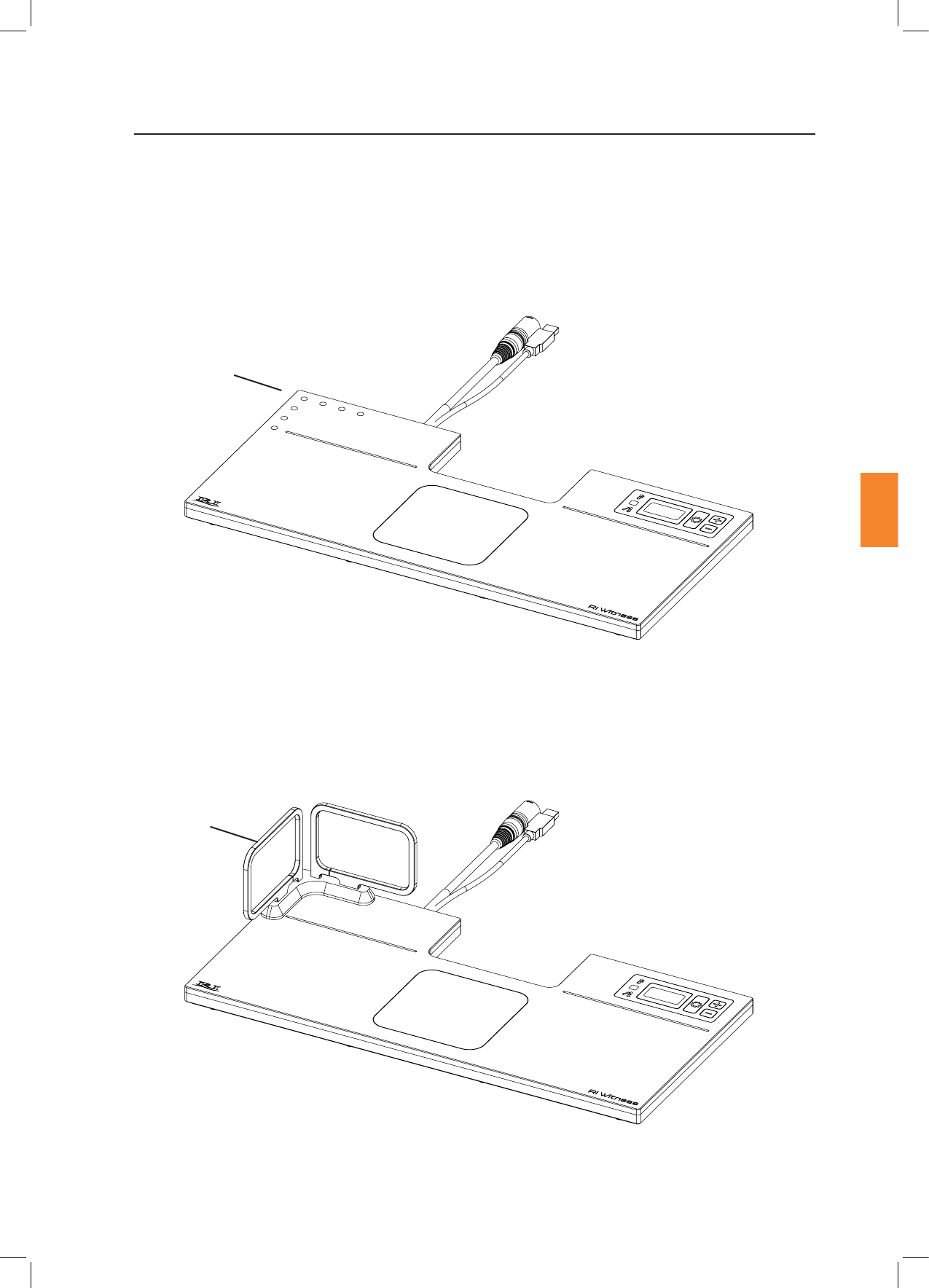
Plug the device into the tablet or PC (or aached USB hub) using the USB A cable that protrudes from
the device. Once the Windows operang system has recognised the devices within the Embryology
Heated Plate, open the RI Witness WorkArea soware. To verify that the RI Witness Work Area soware
can communicate successfully, navigate to the Work Area Status window (click the yellow triangle or
press the icon). This will bring up the Work Area Status window where the ‘Embryology Reader’ and
‘Temperature Control’ should be listed in the Connected Devices secon with a green ck next to them.
For more detailed set up informaon, refer to the RI Witness soware manual (6-70-121UM).
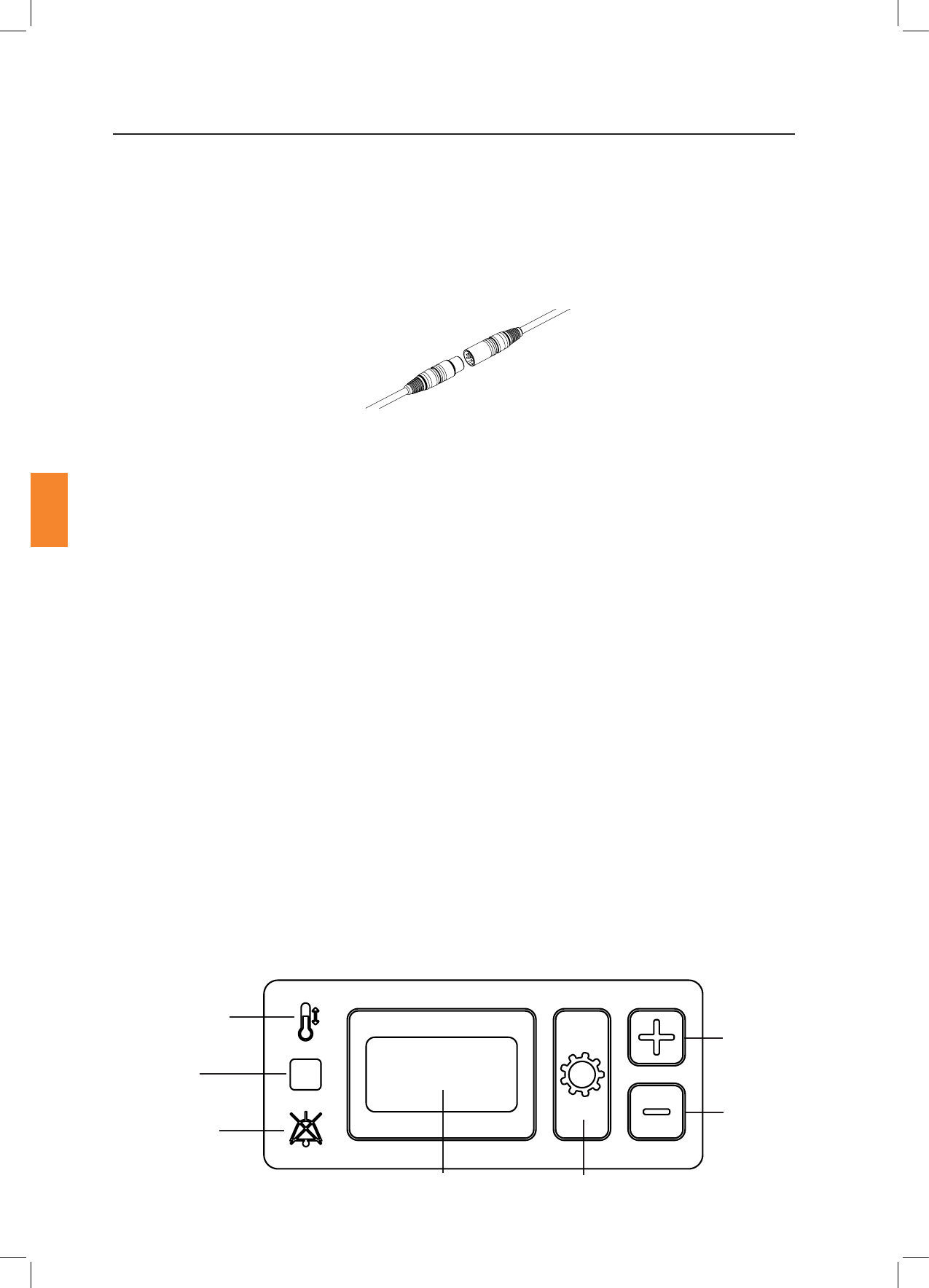
The Embryology Heated Plate contains a built in user interface which allows access to basic temperature
setpoint and calibraon adjustment. A complete set of calibraon opons can only be accessed through
the RI Witness WorkArea soware.
Temperature
Adjustment
Indicator Light
Status
Indicator
Light
Audio O
Indicator Light
Temperature Display
(shows ITO glass
window temperature)
Sengs
Buon
Down Buon
Up Buon
Figure 5-2 User Interface
Figure 5-1 Power Supply In-Line Connector
Secon 5
12
RI Witness™ Basic Operaon
Research Instruments Ltd
5
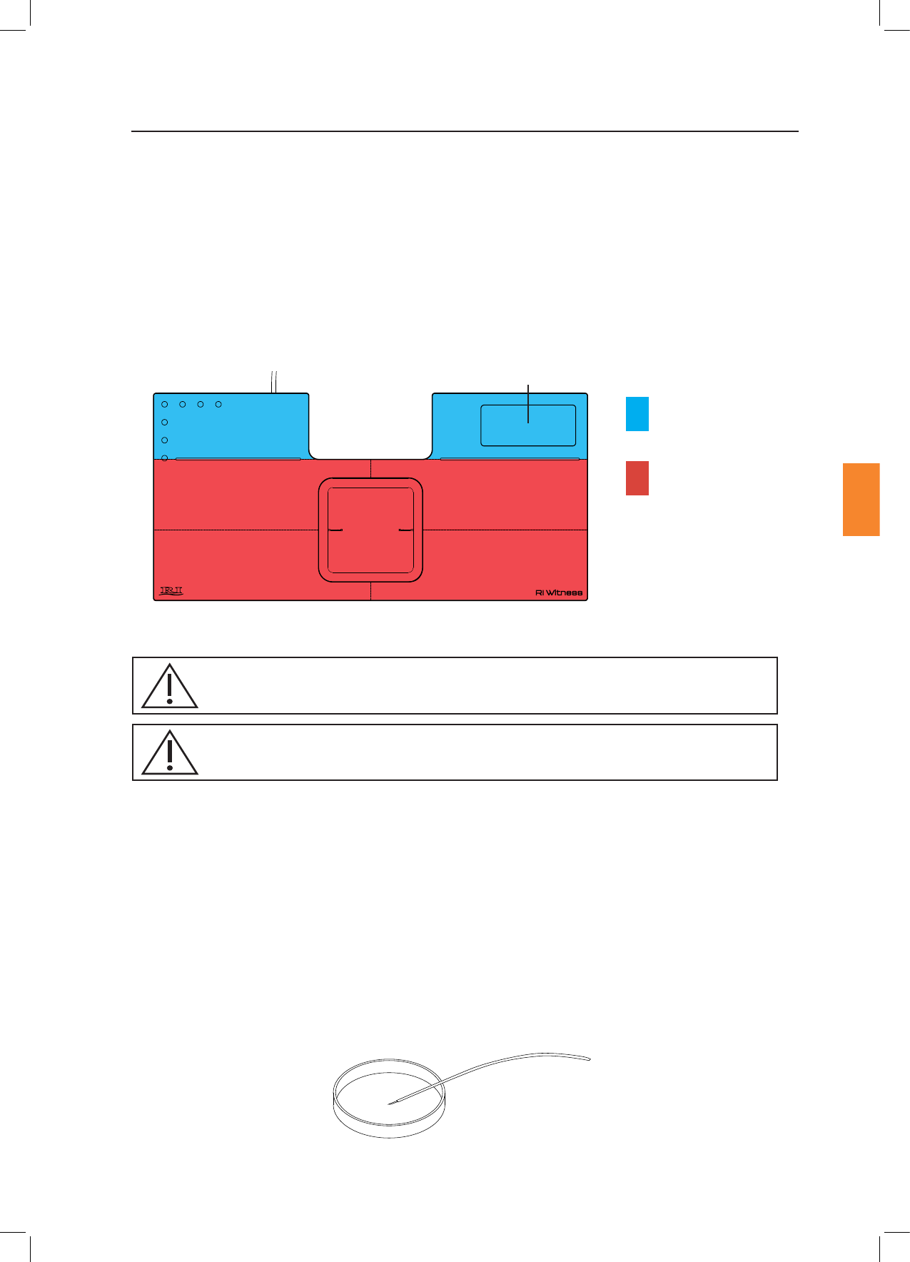
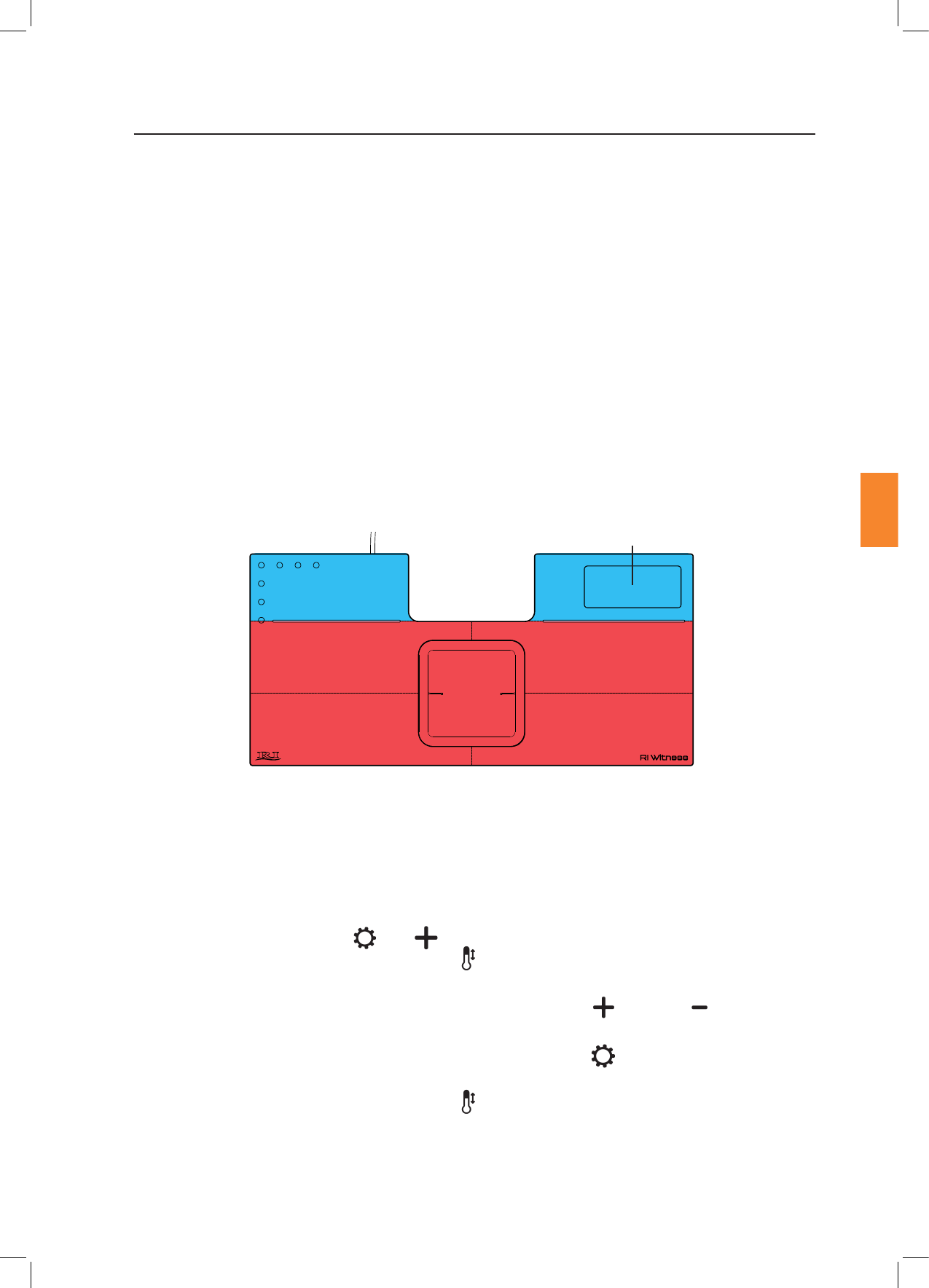
The heated plate is divided into 5 areas for calibraon purposes. In order to achieve the correct sample
temperature place the sample on top of the heated areas shown below. Do not place samples on top
of the User Interface.
Figure 5-4 Thermometer Probe Posioned in a Petri Dish
Figure 5-3 Embryology Heated Plate Heated Areas
User Interface
Top Le
Heated Area
Top Right
Heated Area
Boom Le
Heated Area
Boom Right
Heated Area
Temperatures within the Petri dish are adjusted by changing the setpoint temperature as described on
the next page. The temperature inside a Petri dish will normally be slightly lower than the heated plate,
depending on ambient condions, type of Petri dish and the sample preparaon. Aer the system has
been installed in its operang locaon, the temperature of the heated plate should be adjusted to allow
for this dierence.
We recommend using a thermometer calibrated to 37°C ed with a small thermocouple probe, such
as the RI IVF Thermometer to measure the temperature inside the Petri dish.
Prepare a Petri dish that mimics your normal Petri dish preparaon and place it on the heated surface
in its normal posion. Place the probe of the thermometer in the centre of the dish against the boom
of the dish and allow the temperature reading to stabilise. Adjust the setpoint temperature unl the
desired temperature in the dish is reached, allowing 20 minutes (or as long as required) in between
each setpoint change to allow the Petri dish temperatures to stabilise.
Window
Heated Area
Blue area not
temperature
controlled
Red denotes
heated area
The operator should be posioned in such a place to easily access the User Interface, work surface of the
device and the connected touch screen (if used with the RI Witness WorkArea soware).
Place only plasc or glass ware on the window heated area.
Ambient temperature must be >5°c from the set point for the temperature control
to work eecvely
Secon 5
RI Witness™ Basic Operaon
13
Research Instruments Ltd
5
The maximum setpoint temperature allowed for this device is 45°C.
The temperature setpoint is applied to all heang channels and is set using the following procedure, or
from within the RI Witness WorkArea soware. Refer to the RI Witness Soware Manual (6-70-121UM)
for further informaon.
1. Press and hold the Sengs buon for 3 seconds.
2. The Temperature Adjustment Indicator light will ash. The Temperature Display will now
show the current setpoint (not the current temperature).
3. Adjust the value shown on the Temperature Display using the Up and Down buons
unl the desired setpoint is shown.
4. Save the temperature by pressing and holding the Sengs buon for 3 seconds.
A beep will be heard.
5. The Temperature Adjustment Indicator light will go out and the Temperature Display will
now show the current temperature. Once the temperature has stabilised at the setpoint, the
green Status Indicator Light will illuminate.
To exit the setpoint adjustment mode without saving changes, do not press any buons for 15
seconds and the device will return to normal operaon (the Temperature Adjustment Indicator light
will go out).
To change the setpoint using the RI Witness WorkArea soware, click on the temperature displayed
at the boom right hand side of the screen. This will bring up a pop up box with up and down arrows
which can be used to adjust the setpoint temperature. The temperature controller will then begin
controlling using the new sengs .
Aer adjusng the setpoint temperature, check sample temperature inside the Petri dish.
In the event of sensor failure the plate may become hot (up to 65°C).
Secon 5
14
RI Witness™ Basic Operaon
Research Instruments Ltd
5
Note
Perform calibraon only if the displayed temperature is dierent to the actual surface temperature of
any of the 5 heated areas. The process of calibraon allows the user to manually adjust the temperature
so that the displayed temperatures match the temperature of the surface.
Before temperature calibraon can be performed the device must be in the same condions that it will
be in during normal operaon. The temperature calibraon is aected by ambient condions.
Place the probe of a calibrated thermometer in good thermal contact with the surface.
Simply touching the probe on the surface is not adequate. Use a purpose-made surface probe and
use thermal transfer paste. Products sold for computer heatsinks are suitable, and RI can also supply
suitable materials. Wait at least 30 minutes to allow the temperature to stabilise before calibrang.
Heated areas are divided as shown below, with the ‘X’ denong recommended thermocouple posions
for calibraon:
During calibraon using the built-in user interface close the RI Witness WorkArea soware to
prevent interference with the thermometer reading.
1. Posion the thermocouple probe on the Window in the locaon shown above.
2. Press and hold the Sengs and buons simultaneously for 3 seconds.
The Temperature Adjustment Indicator light will ash. The Temperature Display will now
ash between the current temperature (which may be a changing value) and the leers CAL.
3. Adjust the value shown on the Temperature Display using the Up and Down buons
unl the temperature matches that shown on the external thermometer.
4. Save the calibraon by pressing and holding the Sengs buon for 3 seconds. A beep will
be heard.
5. The Temperature Adjustment Indicator light will go out and the Temperature Display will
now show the current temperature with applied calibraon. Leave the probe in posion and
once the temperature has stabilised at the setpoint, check that the calibraon is accurate.
Repeat the calibraon process if necessary. The green Status Indicator Light will illuminate once
temperatures have stabilised.
User Interface
Top Le Top Right
XX
X X
X
Boom Le
Window
Boom Right
Figure 5-5 Recommended Thermocouple Posions for Temperature Calibraon

Secon 5
RI Witness™ Basic Operaon
15
Research Instruments Ltd
5
6. Aer adjusng calibraon check sample temperatures and adjust the setpoint temperature if
required.
To exit the window calibraon mode without saving changes, do not press any buons
for 15 seconds and the device will return to normal operaon. The Temperature Adjustment
Indicator light will go out and the Temperature Display will stop ashing.
Full calibraon of the 5 heated areas requires that each of the areas is calibrated in turn.
1. Open the RI Witness WorkArea soware and navigate to the WorkArea Status window.
2. Click on the yellow triangle or the icon then click , then Connected
, then Temperature Controller, then . The screen will now show the
current temperature and calibraon osets of the ve dierent heated areas.
RF will be switched o automiacally when on the Temperature Control screen.
3. Each heated area is independent so the order of calibraon is not important. Posion the
thermocouple probe in one of the posions shown above.
4. Allow the reading to stabilise, then compare the temperature shown in the WorkArea soware
with the thermometer reading.
5. A dierence within ± 0.2°C is acceptable. If the readings are outside this increase the oset to
increase the reading displayed by the soware, or decrease the oset to decrease the reading
displayed by the soware to match the temperature displayed by the thermometer.
Allow a small delay for the oset change to register. When changing the oset, the temperature
controller will then begin controlling using the new sengs, so the surface temperature of that
heated area may take a short me to re-stabilise.
6. Repeat this process for all 5 heated areas.
7. Once calibraon is complete it is advisable to verify the temperature of each heated area to
check that temperature calibraon has been carried out eecvely. Aer adjusng calibraon,
check sample temperatures and adjust the setpoint temperature if required.
Secon 5
16
RI Witness™ Basic Operaon
Research Instruments Ltd
5
The Tube Reader Antenna is an accessory for the Embryology Heated Plate that allows tags to be read in
a vercal orientaon. It is specically designed to read tags placed on tubes in the RI Tube Holder. The
Tube Reader Antenna is a passive device that only becomes powered when aached to the Embryology
Heated Plate. The correct mounng orientaon posion is shown below in Figure 5-6.
Refer to “Secon 7- Care and Maintenance” on page 23 for cleaning precauons relang to the Tube
Reader Antenna.
Figure 5-6 Tube Reader Connecons on the Embryology Heated Plate
Figure 5-7 Tube Reader Correctly Mounted on the Embryology Heated Plate
Tube Reader
Antenna
Tube Reader Antenna
Connecons

Secon 6
Troubleshoong
Research Instruments Ltd
6
Tags Not Reading
Metal near reader Remove any metallic objects from the area, check
if the tags come back into Work Area
Loose or no connecon
Check security of USB and power cable
connecons. Verify that the light on the power
supply is illuminated
RF noise or interference
Other electrical devices in the lab can cause RF
noise/interference. If a portable electronic device
has been brought close to the device, remove it
and check if the tags come back into the Work
Area
Broken tag Check whether the tag is readable by a dierent
RI Witness device. If it is not, discard that tag
Antenna tuning
problem
Navigate to the screen,
then click , then
Reader, then , check that all 5
channels (or 3 if you do not have the tube reader
accessory connected) have green cks next to
them. If any have a yellow warning triangle next
to them, contact an RI service representave
Secon 6
18
Troubleshoong
Research Instruments Ltd
6
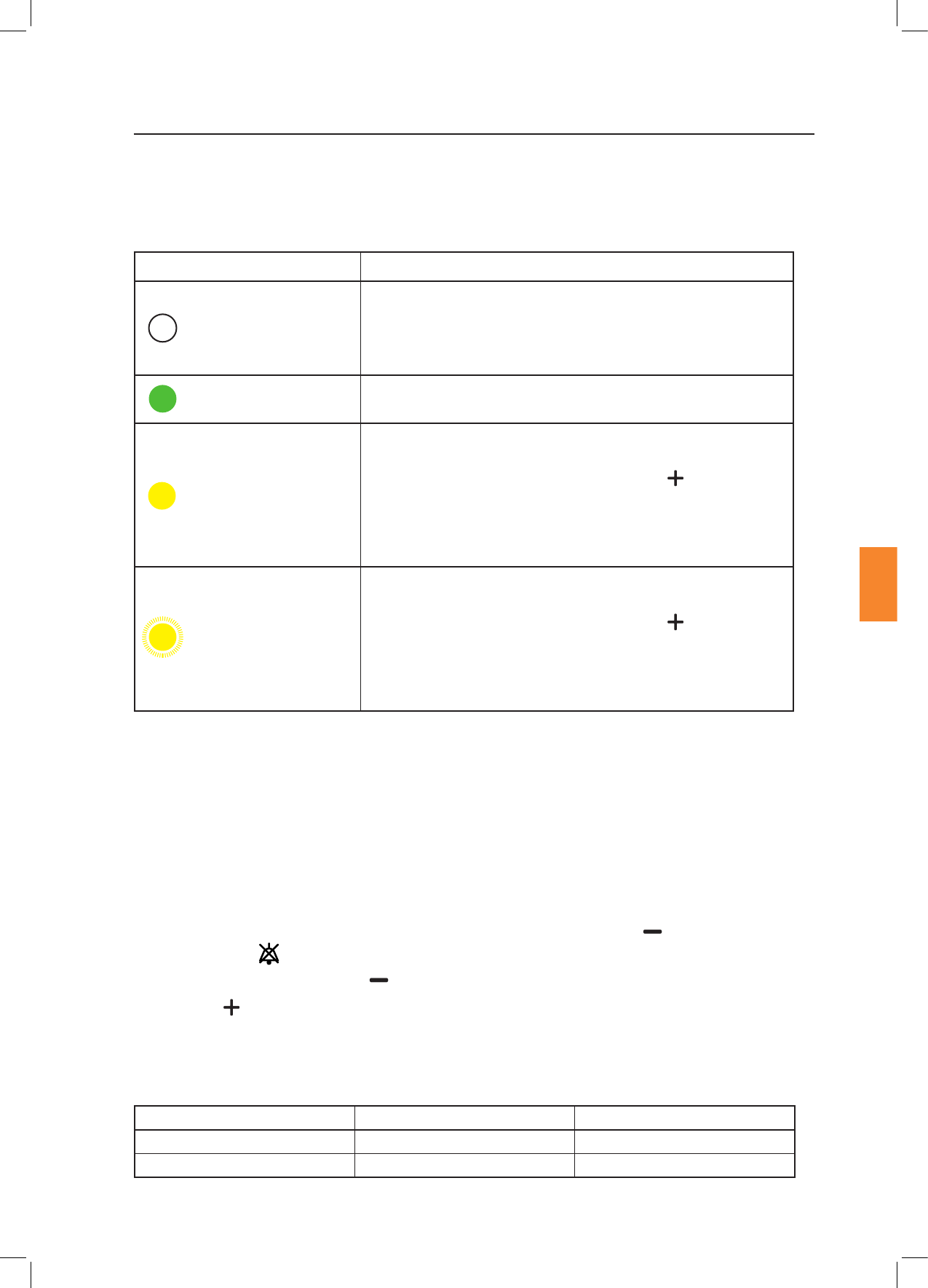
The status of the temperature control system is shown by the Status Indicator Light posioned on the
user interface of the device.
O
Please wait
Inial power up/setpoint/mode/calibraon changed.
The light will be o unl temperature of all heang systems has
stabilised.
Green (constantly on)
Temperature of all heang systems has stabilised.
Yellow (constantly on)
Built-in user interface and RI Witness WorkArea soware will
show current window temperature. Press the buon to
cycle through the Alarm Condion Codes. Refer to tables on the
following pages for details of each code. If the alarm sounds,
nish the current procedure and invesgate the cause of the
alarm.
Yellow (ashing)
Built-in user interface and RI Witness WorkArea soware will
show current window temperature. Press the buon to
cycle through the Alarm Condion Codes. Refer to the tables on
the following pages for details of each code. If the alarm sounds,
nish the current procedure and invesgate the cause of the
alarm.
When mulple alarms are acve, the highest priority alarm will be shown or the icon in the RI Witness
WorkArea Soware, and on the device the Status Indicator Light.
For a full list of possible faults relang to each alarm condion and applicability of each alarm
condion, refer to the tables on the following pages. Alarm Condion Codes are only displayed whilst
the alarm is acve and are cleared when the alarm is no longer acve.
Audible alarms are sounded to indicate Low and Medium Priority Alarms, as described above. When
in alarm condion it is possible to turn the Audio O by pressing the down buon. The Audio
O Indicator Light will illuminate for the duraon of the alarm condion. The Audio will return if
another alarm is acvated or if the buon is pressed again.
Press the Up buon whilst alarms are acve to cycle through the error codes. See pages 19 to 22
for full list of Alarm Condion Codes.
When mulple alarms are acve, the audio for the highest priority alarm will be sounded. The alarm
volume is not adjustable. Audible range for alarm system is as follows.
Medium Priority 44.4 - 55.5dB 53dB
Low Priority 41.5 - 55.5dB 51.5dB

Secon 6
Troubleshoong
Research Instruments Ltd
6
Alarm
Code
Fault
Alarm
E01 ITO Window
Heang Failure
Low Heang system is not
able to heat the specied
heang channel. Alarm
will be acvated 2
minutes aer power
on if there is less than
1.5˚C temperature rise
between 1 and 2 minutes
aer power on. If the
temperature at 1 minute
is already within ± 2.5˚C
from the setpoint the
test is omied.
Heang
controller
power is set
to 0% for
that heang
channel unl
device is
restarted.
Restart the device
by removing mains
power then
re-connecng.
E02 Boom Right
Heang Channel
Failure
E03 Boom Le
Heang Channel
Failure
E04 Top Right
Heang Channel
Failure
E05 Top Le Heang
Channel Failure
Failure Channel
E06 ITO Window
Sensor Failure
Low/
Medium
Low priority
alarm is
acvated
if the fault
occurs when
system is
switched
on. Aer
this me
a medium
priority
alarm is
acvated
No signal/out of range
signal from temperature
sensor. Alarm acvates
at any me if the sensor
circuit fails to read a valid
temperature.
Heang
power is set
to 0% for
that heang
channel
unl a valid
temperature
is read.
If any of the
ITO Window
sensors
fail the
temperature
display will
show
--.-˚C
Possible sensor,
cable or controller
fault.
May also be
caused when the
device is in over
temperature
condion.
Restart the device
by removing the
mains power, then
reconnect.
Contact your
distributor or RI
Service if fault
persists.
E07 Boom Right
Sensor Failure
E08 Boom Le
Sensor Failure
E09 Top Right Sensor
Failure
E10 Top Le Sensor
Failure
In order to test funconality of the alarm system hold down the buon for 3 seconds when there
are no acve alarms. This will trigger a medium priority alarm signal, (3 audible pulses and 3 yellow
ashes of the status indicator light). This check should be performed at regular intervals to reduce the
chance of missing an alarm due to failed loudspeaker or status indicator light.

Secon 6
Troubleshoong
Research Instruments Ltd
6
Alarm
Code
Fault
Alarm
E11 ITO Window
Heang
Channel Over
Temperature
Low /
Medium
If fault
occurs when
the system
is switched
on
Heang channel has
exceeded the maximum
allowable setpoint
temperature. Alarm
acvated at any me if
the temperature sensor
exceeds 50˚C.
Temperature
controller
power is set
to 0% unl
temperature
falls to below
50˚C.
If the
temperature
connues to
rise past this
point, over
temperature
protecon
built in to the
device will
shut down
the heang.
Possible heater or
controller fault.
E12 Boom Right
Heang
Channel Over
Temperature
E13 Boom Le
Heang
Channel Over
Temperature
E14 Top Right
Heang
Channel Over
Temperature
E15 Top Le Heang
Channel Over
Temperature
E16 ITO Window
Heang Channel
Temperature
outside
± 1°C
Medium Heang channel has
deviated by more than
1˚C from the setpoint
temperature. Alarm
enabled 10 minutes aer
the temperature reaches
±2.5˚C from the
setpoint temperature.
The
temperature
controller
connues to
operate to
bring back
within the
allowable
limits.
This may be caused
by placing either
hot or cold objects
on the device, in
parcular the ITO
Window. In this
case either remove
the object or
wait a short me
for the setpoint
temperature to be
reached. Sudden
air movements
or temperature
change can also
cause minor
temperature
uctuaons. In
this case wait a
short while for
the temperature
controller to
respond.
E17 Boom Right
Heang Channel
Temperature
outside
± 1°C
E18 Boom Le
Heang Channel
Temperature
outside
± 1°C
E19 Top Right
Heang Channel
Temperature
outside
± 1°C
E20 Top Le Heang
Channel
Temperature
outside
± 1°C

Secon 6
Troubleshoong
21
Research Instruments Ltd
6
Alarm
Code
Fault
Alarm
E21 ITO Window
Heang Channel
Temperature
outside
± 2.5°C
Medium Heang channel has
deviated by more than
2.5˚C from the setpoint
temperature. Alarm
enabled once it has
reached ±2.5˚C from the
setpoint temperature
and is more than 1
minute aer power on.
The
temperature
controller
connues to
operate to
bring back
within the
allowable
limits.
This may be caused
by placing either
hot or cold objects
on the device, in
parcular the ITO
Window. In this
case either remove
the object or
wait a short me
for the setpoint
temperature to be
reached. Sudden
air movements
or temperature
change can also
cause minor
temperature
uctuaons. In
this case wait a
short while for
the temperature
controller to
respond.
May also be
caused when the
device is in over
temperature
condion.
Restart the device
by removing the
mains power, then
reconnect.
Contact your
distributor or RI
Service if fault
persists.
E22 Boom Right
Heang Channel
Temperature
outside
± 2.5°C
E23 Boom Le
Heang Channel
Temperature
outside
± 2.5°C
E24 Top Right
Heang Channel
Temperature
outside
± 2.5°C
E25 Top Le Heang
Channel
Temperature
outside
± 2.5°C

Secon 6
22
Troubleshoong
Research Instruments Ltd
6
Alarm
Code
Fault
Alarm
E26 ITO Window
Heang Channel
Low Heang
Rate
Medium Heang controller
did not achieve a
temperature within 2.5˚C
of the setpoint in 15
minutes from power on.
Temperature
controller
connues to
operate.
If the device is
operated in an
environment
where the ambient
temperature is
colder than the
specied operang
condions or if
there is a large
amount of cold
airow over the
device, then
this alarm may
triggered rounely.
If neither of these
condions are
present, restart the
device. If the fault
reoccurs contact
an RI Service
personnel.
E27 Boom Right
Heang Channel
Low Heang
Rate
E28 Boom Le
Heang Channel
Low Heang
Rate
E29 Top Right
Heang Channel
Low Heang
Rate
E30 Top Le Heang
Channel
Low Heang
Rate
E31 Memory Fault Low Memory/controller
fault. System failed
to read or write data
correctly. If it happens
during run me the
system will carry on
with current data. If it
happens during start
up the system will load
the default values and
needs reconguraon of
setpoint calibraon.
System
connues to
operate
unl power
is removed.
When power
is returned
the system
will operate
with the
default
calibraon
and setpoint
values.
Set the setpoint
temperature then
re-calibrate. If the
problem persists
then there may
be a fault with the
controller. If the
problem is resolved
then the memory
may have been
corrupted during
saving of values, eg
if the device loses
power whilst saving
values.
Secon 7
Care and Maintenance
23
Research Instruments Ltd
7
RI Witness Embryology Heated Plate and Tube Reader Antenna may be cleaned with a so cloth and
mild detergent. Do not disconnect the cables aached to the device.
If the Tube Reader Antenna is removed for cleaning be mindful to allow the contact surfaces on both the
Heated Plate and the Tube Reader Antenna to fully dry before reaaching to ensure cleaning products
are not trapped in the interface.
Do not use solvents for cleaning.
Do not disconnect readers.

Secon 8
24
Repairs and Returns
Research Instruments Ltd
8
Reuse Statement
Assuming RI Witness is regularly maintained and rounely serviced, it should perform as required for
a minimum of 7 years connual use, aer which me we recommend you consider its replacement.
Should you noce impaired performance and/or any issues where safety is compromised, or have any
other concerns during the use of RI Witness, seek the advice of RI or their authorised representave
promptly.
In the event that you have a problem with a RI instrument, please follow the procedure below to ensure
prompt aenon.
1. Read the ‘Troubleshoong’ secon.
2. If you require any further help contact your distributor or RI directly. RI will try to resolve the
problem as quickly as possible.
If the product is no longer serviceable it must be sent back to RI to be destroyed in an
environmentally safe way. Do not dispose of this device with ‘normal’ waste.
1. Contact RI to obtain a Returned Materials Authorisaon (RMA) number.
Goods will not bereplaced or refunded without prior agreement and clearly stang the
RMA number.
2. Pack the item carefully in its original packaging. RI will not accept responsibility for damage due
to incorrect packaging. Replacement items or addional repairs will be invoiced.
3. Clearly label the package with the RMA number, mark the package “Urgent - Returned Items For
Repair”, and ship to the address on the next page. Goods should be insured for their full value
during shipping.
Research Instruments Ltd, Bickland Industrial Park,
Falmouth, Cornwall, TR11 4TA, UK
Tel: +44 (0) 1326 372 753 Fax: +44 (0) 1326 378 783
E-mail: service@research-instruments.com
Website: www.research-instruments.com
In compliance with the European Medical Device Direcve 93/42/EEC as amended, it is your duty to
inform RI if you believe this device has, or may have, caused or contributed to the death of a paent or
user or to a serious deterioraon in their state of health.
Thank you for purchasing a RI product. To help RI develop the best tools for ART, we rely on customer
feedback. If you have any suggesons for how we can improve our products or the informaon we
provide with them, please send them to feedback@research-instruments.com. Your feedback will help
us develop the product and supporng materials to meet your future needs.
Thank you.
