RF Technology DBS150 VHF BASE STATION/ REPEATER TRANSCEIVER User Manual Eclipse2 manual FCC
RF Technology Pty Ltd VHF BASE STATION/ REPEATER TRANSCEIVER Eclipse2 manual FCC
UserManual.wiki
>
RF Technology
>
DBS150 User Manual
USERS MANUAL
Navigation menu
Upload a User Manual
Namespaces
Wiki Guide
HTML
PDF
Info
Views
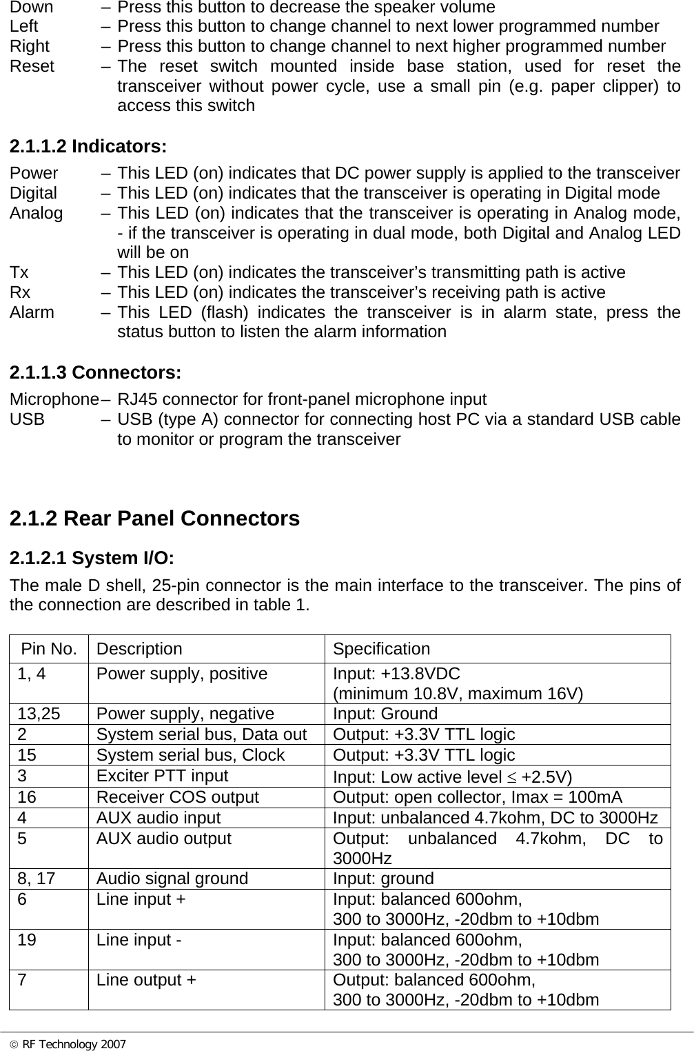
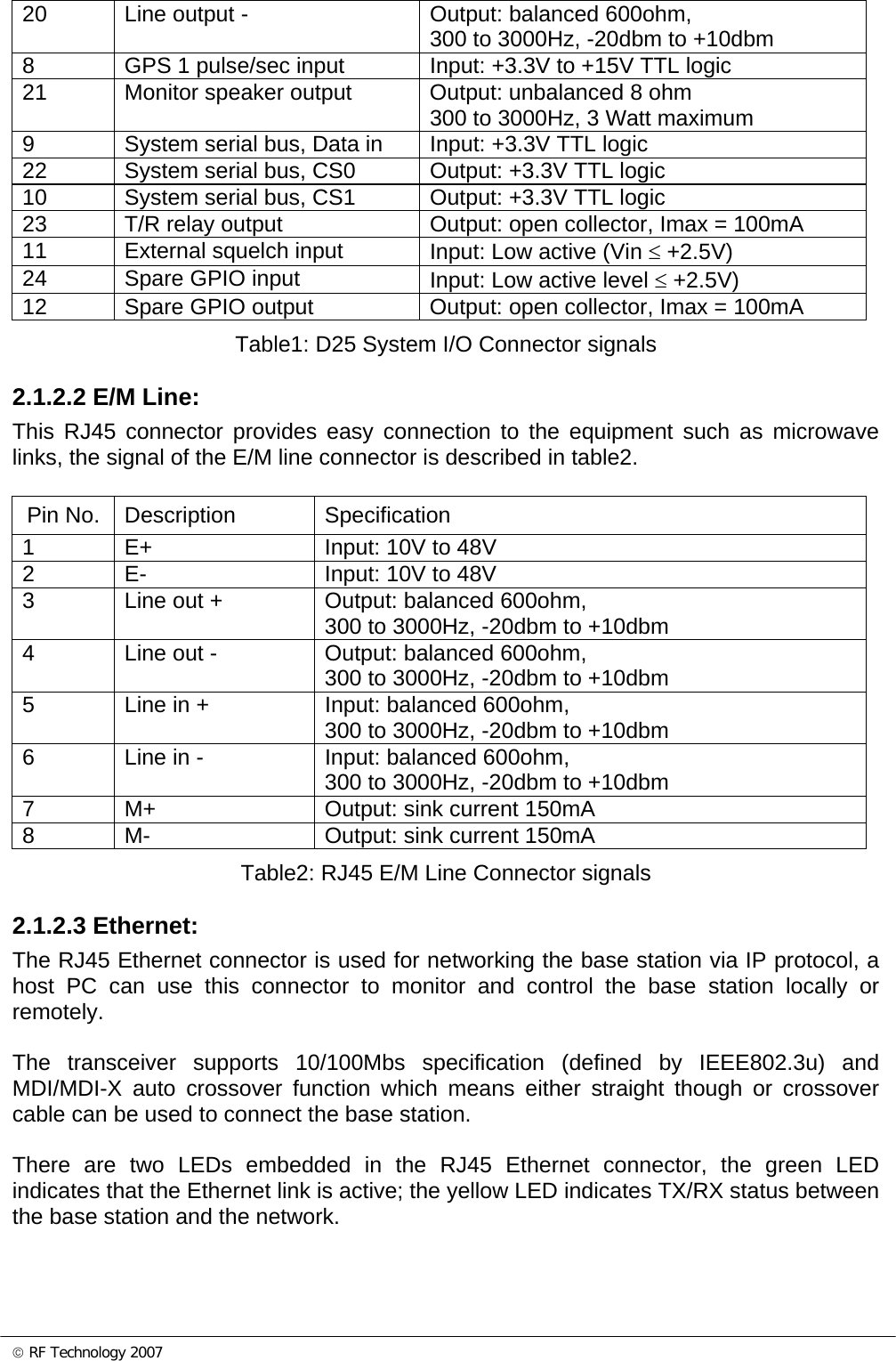
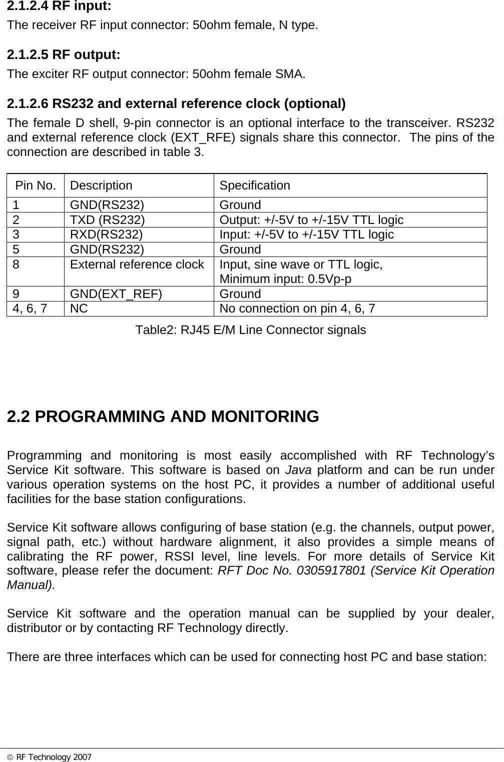
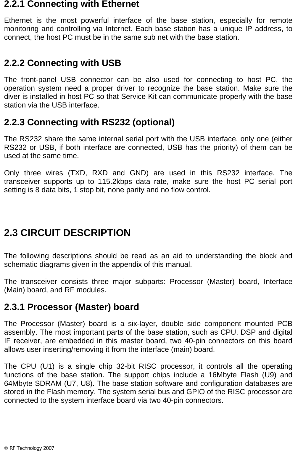
User Manual
Discussion / Help
Navigation