RSI VIDEOTECHNOLOGIES XL00 Monitoring Device User Manual Product Catalog
RSI VIDEOTECHNOLOGIES Monitoring Device Product Catalog
UserManual.wiki
>
RSI VIDEOTECHNOLOGIES
>
XL00 User Manual
User Manual
Navigation menu
Upload a User Manual
Namespaces
Wiki Guide
HTML
PDF
Info
Views
User Manual
Discussion / Help
Navigation

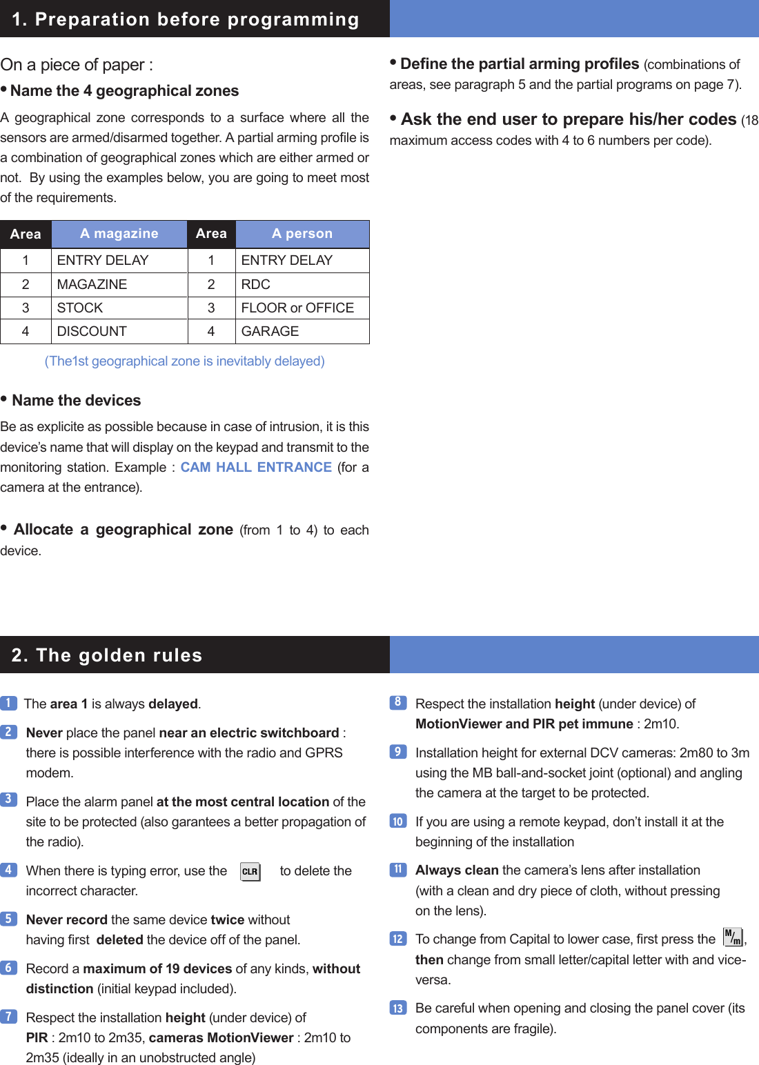
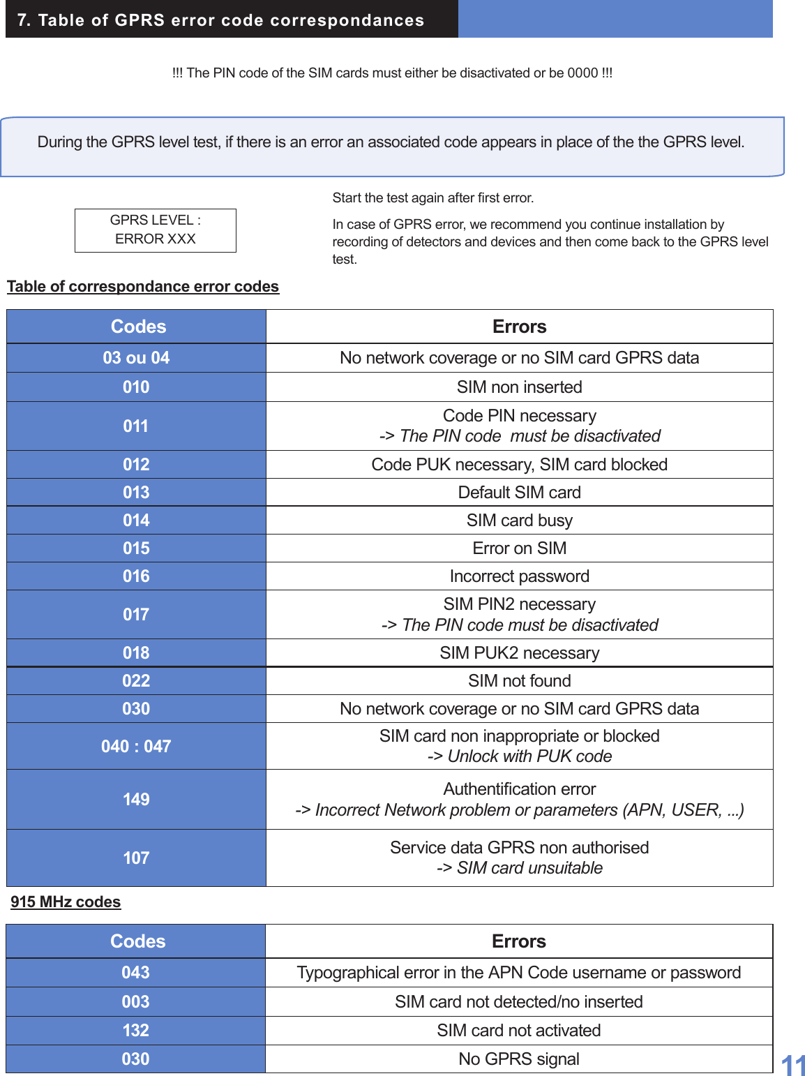
![003 Videofied Security System Installation Manual The keypad becomes inactive after 40 seconds of inactivity, in order to make the display to reappear, press on the [YES] key.15 Use alkaline batteries for the panel and for the interior and exterior sirens.3. Installation and programming2. The golden rulesOpen the packaging box and take out the cardboard divider which serves as a gauge. Position it level against the attachment tting, making sure the arrow is pointing upwards. Mark the 5 points, remove the gauge and pierce the 4 attachment holes and the auto-protection hole. Attach the base. Insert the 8 alkaline batteries in their lodgings, paying attention to the correct alignment of the positive and negative charges.Before removing the front side of the packaging box, insert the SIM card (voice/data or GSM/GPRS) as illustrated in gures 1 and 2.Assemble the front side with the base by positioning the hinges on the base.3.1 Initialize the panel• Insert the power cable into the power connection (the panel emits a beep) and the keypad lights up and ashes.• Hold down the PROGRAM BUTTON on the panel for 10 seconds untiil the keypad beeps again and lights up all the keys of the panel keypad.• Briey press the PROGRAM BUTTON of the panel again to switch to keypad registration mode.3.2 Record the keypad (cf. Keypad installation manual)• Insert the 3 Lithium LS14500 batteries in the keypad.• Do not x the keypad, it will help you in the recording and setting of the devices.• Simultaneously press on [CLR] and [ESC NO] buttons on the keypad, until the keypad’s indicator ashes and then release.3.3 Close the panel cover• Screw in the screw on the left of the box.16 The ITRA110/600 and DCVA200/600/700 (devices with pet immune) should never be placed in stairs, or near stairs. (Risk of untimely triggerings).14Figure 1 Figure 2Base HingesPROGRAM ButtonAlkaline batteriesPower connectionPower cable](https://usermanual.wiki/RSI-VIDEOTECHNOLOGIES/XL00/User-Guide-1249523-Page-5.png)
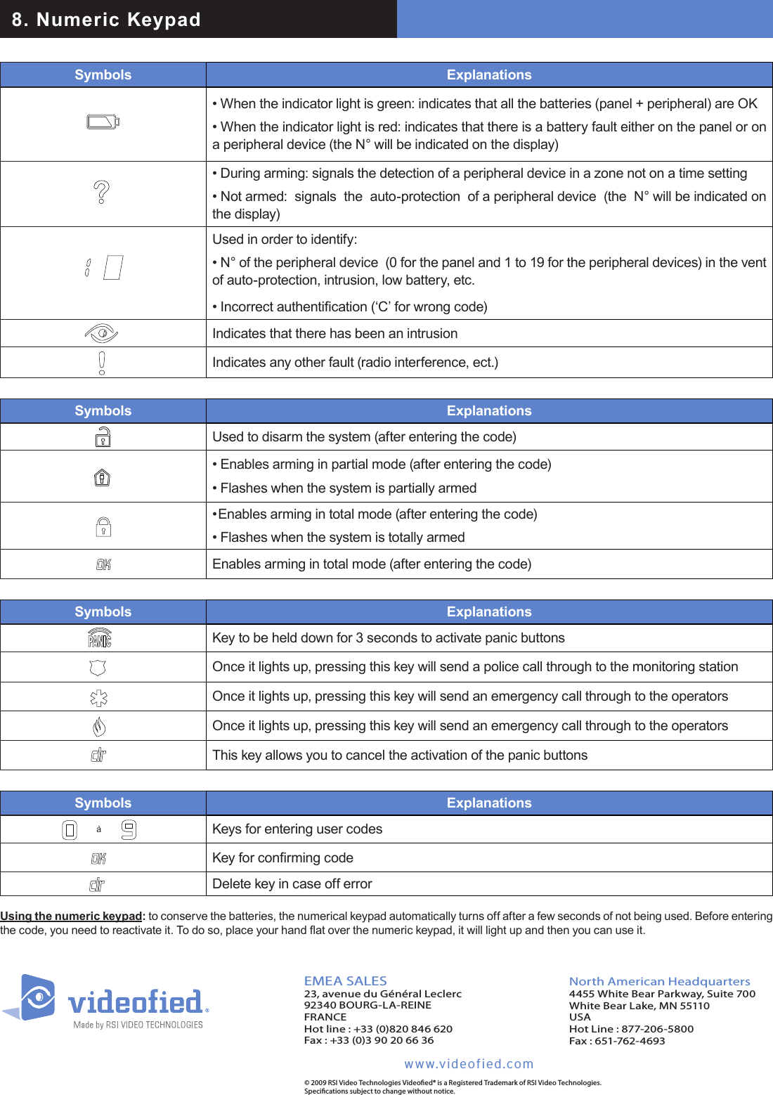
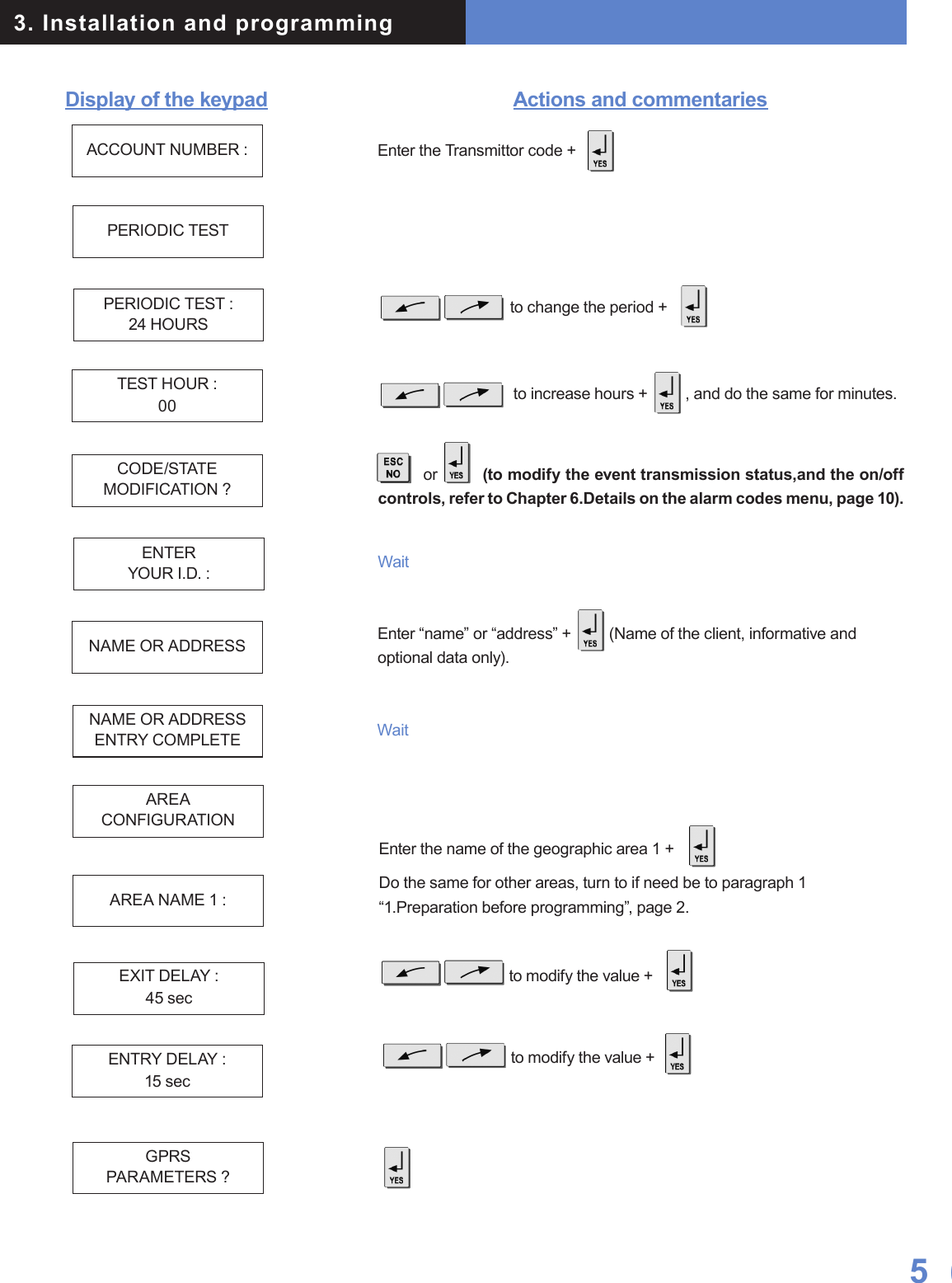
![Display of the keypad3. Installation and programmingActions and commentariesKEYPAD 1RECORDEDRADIO RANGETEST ?RADIO RANGEx/9RADIO RANGE9/9RADIO RANGETEST ?ENTER THEINSTALLER CODE 4 TO 6 DIGITSTHEN YESINSTALLER CODE :CODE NAME :ADJUSTINGTIME AND DATEDATE (Year) :00/ /CONNECTED TO MONITOR STATION?Do the same for the Month, the Day, the Time and the Minutes.Wait Use direction arrows right or left to increase the numbers and the [YES] key to validate the value and move to the next.Naming the code + (Becareful, some NAMES correspond to pre-programming of key accounts. (In case of incorrect setting, please contact your technical department).Installer code + , then conrm : Code +WaitWaitWait for 10s in order to obtain the rst stable valueVerify the range : A regular ashing or a value of 2/5 or better indicates a sufcient RF radio.In order to stop the test.< - LANGUAGE - >ENGLISH to select the language.](https://usermanual.wiki/RSI-VIDEOTECHNOLOGIES/XL00/User-Guide-1249523-Page-6.png)
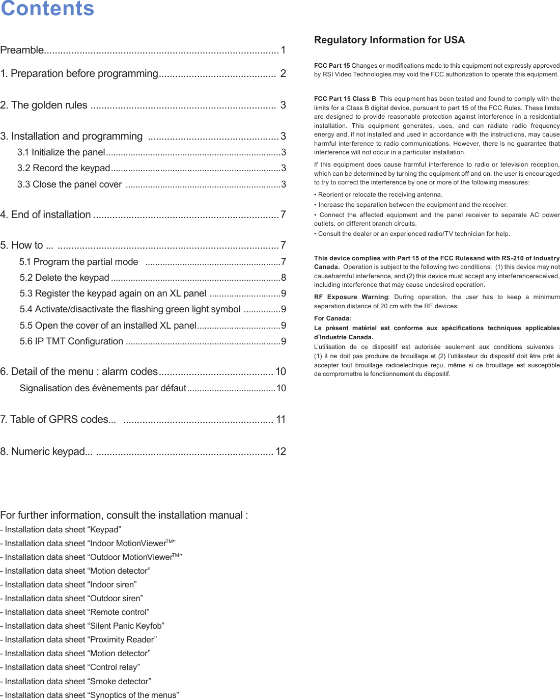
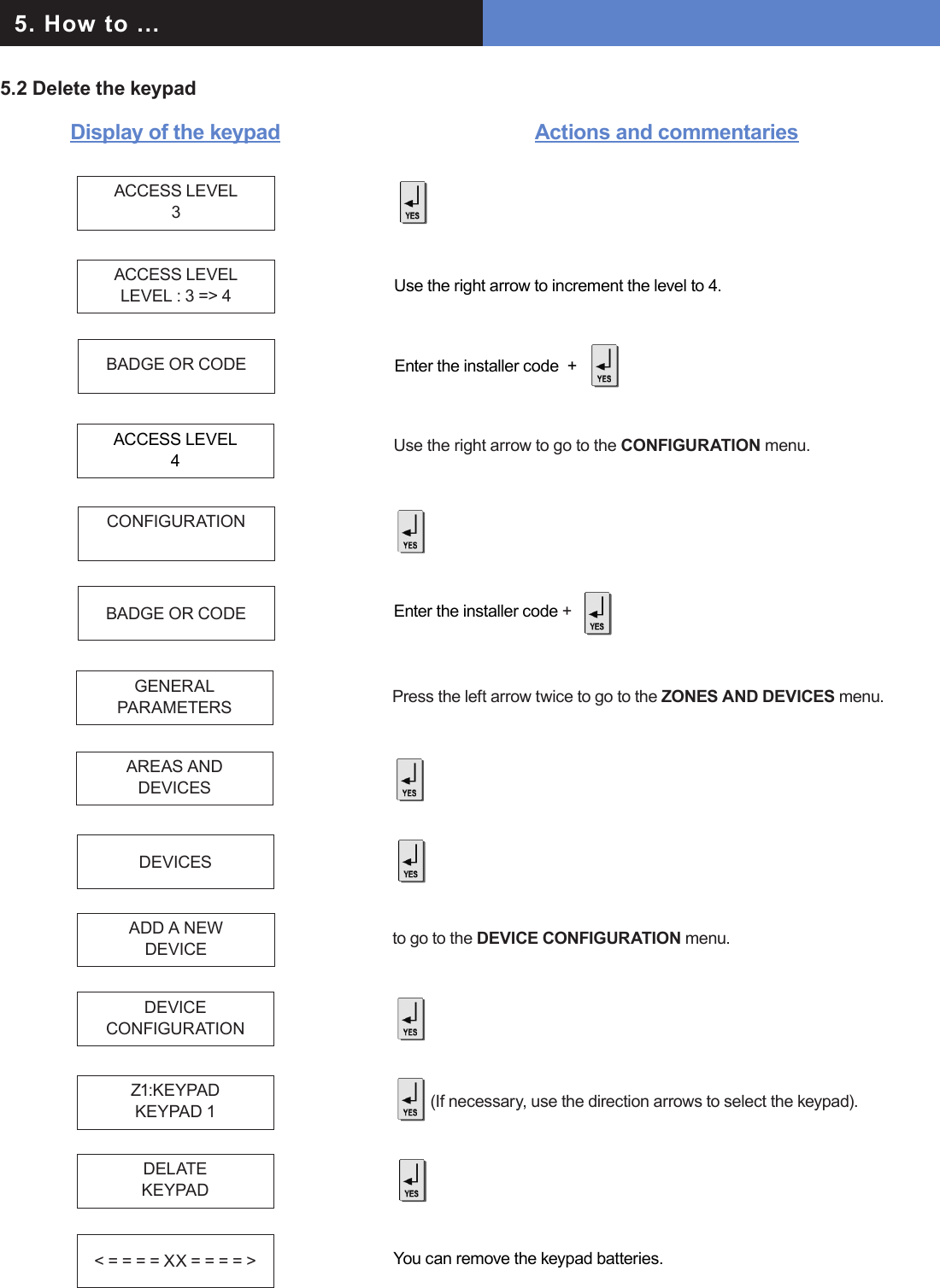
![3. Installation and programmingDisplay of the keypad Actions and commentariesBy default your GPRS panel has parameters of the ORANGE operator. It is necessary to modify the 3 parameters that characterise the connection to another operator (SFR or BOUYGUES, WYLESS, T-MOBILE, ATT...).Remark : GPRS Parameters is Case Sensitive ! (use the M/m key of the keypad to change Capital /Small letters).Be careful : Use arrows to change from one parameter to the other. Press on the [YES] key only when you want to modify a parameter!(The APN is given by your operator. These parameters are likely to change following the SIM card used. Ask your operator.)APN CODEinternet-entreprUSER NAMEorangePASSWORDorangeIP1 ADRESS0.0.0.0DOMAIN NAME 1PORT 1888GPRSPARAMETERS ? to exit the menu.TEST IN PROGRESSEND = YESGPRS LEVEL5/5 It is not advisable to install a panel whose level is inferior to 3/5.Wait (this could last for 3 minutes) for the result of the test which can be : - a level between 1/5 and 5/5- an error code (in this case, call you technical support)PRESS PROGRAMBUTTON OF DEVICERecord your devices : (please refer to installation data sheets of each device).GPRS LEVEL Press the and wait for the reception level. Do not remove the SIM card during the test!You are going to enter various parameters depending on which GPRS operator’s SIM card you have.The rst parameter is the APN code.By default, the standard public access parameters are those of Orange.Press [YES] to modify the value or the right arrow to move on to the next parameter.Second parameter: USERNAME Third parameter: PASSWORDThe IP1 address or the domain name and Port 1 are provided by the monitoring station. Likewise for the IP2 address and the IP TMT address if applicable. Once the values have been established,Press the to return to the PARAMETRES GPRS menu. ORANGE SFR BOUYGUES ........................APN internet-entreprise m2minternet a2bouygtel.com ........................USER orange Open eld Open eld ........................PASS orange Open eld Open eld ........................](https://usermanual.wiki/RSI-VIDEOTECHNOLOGIES/XL00/User-Guide-1249523-Page-8.png)
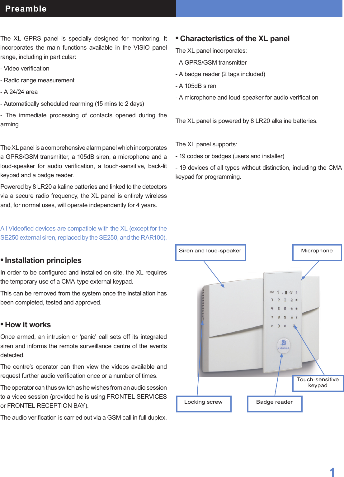
![007Videofied Security System Installation Manual4. End of installationYou have recorded and x all the devices, record the remote controls, then with the question :Display of the keypad Actions and commentariesENTERING A NEWDEVICE ?OPERATIONCOMPLETED ?SYSTEM CHECKIN PROGRESSINSTALATIONSUCCESSFUL ! (Close the cover of the panel)All that remains is to program the user codes, Partial arming modes and eventually the Intercom time (at 180 seconds).5. How to...5.1 Program partial modeWith the direction arrows go to the menuCONFIGURATION (niv 4) -> ALARM MODES PROGRAMMABLES -> FULLY ARMED Then use the direction arrows to select the relevant arming mode and the [YES] key to modify it.There are three possible arming modes.NORMAL MODE is the general arming mode, set using a badge or with a user code and keys or .MODE SPECIAL1 is a partial mode activated by entering a user code and pressing the . This mode is also accessible on a CMA keypad via the and via an RC remote control via the .SPECIAL2 MODE is not accessible on the keypad of an XL panel. It is available on a CMA keypad via the and via an RC remote control via the .For each arming mode, it is possible to specify how each of the 4 zones will be armed and how the sound alert will be made.Areas : 1 2 3 4 Each time you press on the number of the area it modies the correspondance.State : A A A A Situated below. Validation at the end, the [YES] key.A Armed Siren Immediate triggering of all sirensDDisarmed Delay beepsEntry/Exit delay beeps, then triggering of the sirensPPerimeter(all the opening contacts)Silent Without siren without beepsEExternal (opening contacts protecting an exterior access)Without sirenBeeps on the keypad onlyPERIMETRIE MODE is not accessible on the XL keypad. It is only availble on the CMA deported keypad by + user code + [YES].You can now close the XL panel, making sure you fully tighten the screw on the left-hand side.](https://usermanual.wiki/RSI-VIDEOTECHNOLOGIES/XL00/User-Guide-1249523-Page-9.png)
![00Videofied Security System Installation Manual 95. How to ...5.3 Register again a CMA keypad on an XL panel without opening the coverActivate the touch-sensitive keypad by placing your hand over it.Enter in special mode by pressing for 3 seconds on theand the numerical keypad starts to ash.Type the code 000000 then to switch the XL panelin keypad registration mode. On the keypad:- Insert the 3 Lithium LS14500 batteries.- Simultaneously press [CLR] and [ESC NO] on the keypad untiil the indiicator light on the panel ashes and then release.It is possible to activate or disactivate the ashing green battery symbol.Bear in mind that when this symbol is activated, the product has less battery life and the batteries will have to be changed within 4 years.Enter in special mode by pressing for 3 seconds on the and the numerical keypad starts to ash.Type the code 000100 then the digital keypad will remain illuminated while the green battery symbol starts to ash with the number 0 or 1 on the 7-segment digit.The number shown is an indication of the display conguration for the battery symbol (0 for disactivated, 1 for activated). 5.4 Activate or disactivate the flashing green battery symbol5.5 Open the cover of an installed XL panelUnscrew the screw on the left-hand side of the panel and separate the panel of the base. KEYPAD 1 RECORDEDINSTALLATION CODE Enter the installer code +Display of the keypad Actions 5.6 IP TMT ConfigurationYou need a computer connected to the network IP, congured either on a xed address IP with the opened port 888 is needed, or on a name of domain with the opened port 888.About the programming of the panel, it is necessary either to inform on the IP TMT your xed IP, or on DOMAIN NAME your domain name.The computer connected on your network has to have the software Fontel TMT installed and parametrized.The connection by seizing 999999 + [OK] on the panel XL, either on the keypad CMA (if it is on the site).In Frontel TMT make: File / open, a window opens with the account N ° (code transmitter).Click above, validate the request of remote maintenance by clicking on OK, then to make an import to get back the programming of the site.](https://usermanual.wiki/RSI-VIDEOTECHNOLOGIES/XL00/User-Guide-1249523-Page-11.png)
![6. Details of the menu : ALARM CODESignalling events by default (except if you are using pre programming)By default these events are transmited:DEVICE (intrusions)ALERT (button)TAMPERPERIODIC TESTBy default are not transmited:INITIALIZATIONPANEL BATTERIES (low panel batteries)AC POWER (panel power off)PHONELINE FAULT (telephone)DEVICE BATT. (low batteries devices)RADIO JAMMING (radio jamming)SUPERVISION (default supervision)WRONG CODES (when entering 5 false codes/badges)DURESS CODE (panic button)ALARM MEMORY (old memory overwritten)ARM/DISARM (open/close)There are the 3 transmission states:ALARM, which can be heard : when it appearsALARM / END, which can be heard : when it appears and disap-pearsNOT TRANSMITTEDExamples : - If one wishes to recall events of ARMING/DISARMING (operate/stop), you will have to modify the conguration of events ARMING/DISARMING to ALARM / END.- If you wish to recall the false codes information, you will have to modify the conguration of events WRONG CODES on the state ALARM.How to modify the transmission state of events?2 possible solutions:• At installation, just after having validated the hour of the cyclic test, the keypad requests : CODE/STATEMODIFICATION ?• After the initial installation, by using the keypad : With direction arrows go to the menu CONFIGURATION (level 4) -> CONFIGURATION MONITOR. STATION -> ALARM CODES -> TRANS. STATE MODIFICATIONThen:With direction arrows Select the event to transmit, make then modify the transmission state with arrows and revalidate with the [YES] key. Renew the operation for each event which you wish to modify the transmission regulations.Press on the to access the menu TRANS. STATE MODIFICATIONIn all cases, be sure to check that the conguration of your XL system is suitable for your needs.](https://usermanual.wiki/RSI-VIDEOTECHNOLOGIES/XL00/User-Guide-1249523-Page-12.png)