RSI VIDEOTECHNOLOGIES XL00 Monitoring Device User Manual Product Catalog
RSI VIDEOTECHNOLOGIES Monitoring Device Product Catalog
User Manual
Subscriber linked to the monitor station by GPRS
Made by RSI VIDEO TECHNOLOGIES Document No. 2100-XL Jan. 2010
for video and audio conrmation
EMEA Hotline : +33 (0)820 846 620 / UK : 0871 951 / Espagne : +34 90 166 77 00
USA Hotline : 877-206-5800
Installation
Manual
Security System Videofied® - Model XL GPRS
XL GPRS means XL600GPRS for USA/Canada, XL700GPRS for Australia and
XL200GPRS for Europe and rest of the world.
Regulatory Information for USA
FCC Part 15 Changes or modications made to this equipment not expressly approved
by RSI Video Technologies may void the FCC authorization to operate this equipment.
FCC Part 15 Class B This equipment has been tested and found to comply with the
limits for a Class B digital device, pursuant to part 15 of the FCC Rules. These limits
are designed to provide reasonable protection against interference in a residential
installation. This equipment generates, uses, and can radiate radio frequency
energy and, if not installed and used in accordance with the instructions, may cause
harmful interference to radio communications. However, there is no guarantee that
interference will not occur in a particular installation.
If this equipment does cause harmful interference to radio or television reception,
which can be determined by turning the equipment off and on, the user is encouraged
to try to correct the interference by one or more of the following measures:
• Reorient or relocate the receiving antenna.
• Increase the separation between the equipment and the receiver.
• Connect the affected equipment and the panel receiver to separate AC power
outlets, on different branch circuits.
• Consult the dealer or an experienced radio/TV technician for help.
This device complies with Part 15 of the FCC Rulesand with RS-210 of Industry
Canada. Operation is subject to the following two conditions: (1) this device may not
causeharmful interference, and (2) this device must accept any interferencereceived,
including interference that may cause undesired operation.
RF Exposure Warning: During operation, the user has to keep a minimum
separation distance of 20 cm with the RF devices.
For Canada:
Le présent matériel est conforme aux spécications techniques applicables
d’Industrie Canada.
L’utilisation de ce dispositif est autorisée seulement aux conditions suivantes :
(1) il ne doit pas produire de brouillage et (2) l’utilisateur du dispositif doit être prêt à
accepter tout brouillage radioélectrique reçu, même si ce brouillage est susceptible
de compromettre le fonctionnement du dispositif.
Preamble......................................................................................1
1. Preparation before programming ........................................... 2
2. The golden rules .................................................................... 3
3. Installation and programming ................................................3
3.1 Initialize the panel .......................................................................3
3.2 Record the keypad .....................................................................3
3.3 Close the panel cover ...............................................................3
4. End of installation .................................................................... 7
5. How to ... ................................................................................. 7
5.1 Program the partial mode .......................................................7
5.2 Delete the keypad .....................................................................8
5.3 Register the keypad again on an XL panel .............................9
5.4 Activate/disactivate the ashing green light symbol ...............9
5.5 Open the cover of an installed XL panel ..................................9
5.6 IP TMT Conguration ...............................................................9
6. Detail of the menu : alarm codes ..........................................10
Signalisation des évènements par défaut ....................................10
7. Table of GPRS codes... ....................................................... 11
8. Numeric keypad... ................................................................. 12
For further information, consult the installation manual :
- Installation data sheet “Keypad”
- Installation data sheet “Indoor MotionViewerTM”
- Installation data sheet “Outdoor MotionViewerTM”
- Installation data sheet “Motion detector”
- Installation data sheet “Indoor siren”
- Installation data sheet “Outdoor siren”
- Installation data sheet “Remote control”
- Installation data sheet “Silent Panic Keyfob”
- Installation data sheet “Proximity Reader”
- Installation data sheet “Motion detector”
- Installation data sheet “Control relay”
- Installation data sheet “Smoke detector”
- Installation data sheet “Synoptics of the menus”
Contents
1
Preamble
The XL GPRS panel is specially designed for monitoring. It
incorporates the main functions available in the VISIO panel
range, including in particular:
- Video verication
- Radio range measurement
- A 24/24 area
- Automatically scheduled rearming (15 mins to 2 days)
- The immediate processing of contacts opened during the
arming.
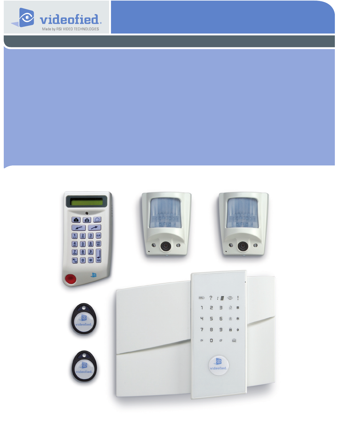
The XL panel is a comprehensive alarm panel which incorporates
a GPRS/GSM transmitter, a 105dB siren, a microphone and a
loud-speaker for audio verication, a touch-sensitive, back-lit
keypad and a badge reader.
Powered by 8 LR20 alkaline batteries and linked to the detectors
via a secure radio frequency, the XL panel is entirely wireless
and, for normal uses, will operate independently for 4 years.
All Videoed devices are compatible with the XL (except for the
SE250 external siren, replaced by the SE250, and the RAR100).
• Installation principles
In order to be congured and installed on-site, the XL requires
the temporary use of a CMA-type external keypad.
This can be removed from the system once the installation has
been completed, tested and approved.
• How it works
Once armed, an intrusion or ‘panic’ call sets off its integrated
siren and informs the remote surveillance centre of the events
detected.
The centre’s operator can then view the videos available and
request further audio verication once or a number of times.
The operator can thus switch as he wishes from an audio session
to a video session (provided he is using FRONTEL SERVICES
or FRONTEL RECEPTION BAY).
The audio verication is carried out via a GSM call in full duplex.
• Characteristics of the XL panel
The XL panel incorporates:
- A GPRS/GSM transmitter
- A badge reader (2 tags included)
- A 105dB siren
- A microphone and loud-speaker for audio verication
The XL panel is powered by 8 LR20 alkaline batteries.
The XL panel supports:
- 19 codes or badges (users and installer)
- 19 devices of all types without distinction, including the CMA
keypad for programming.
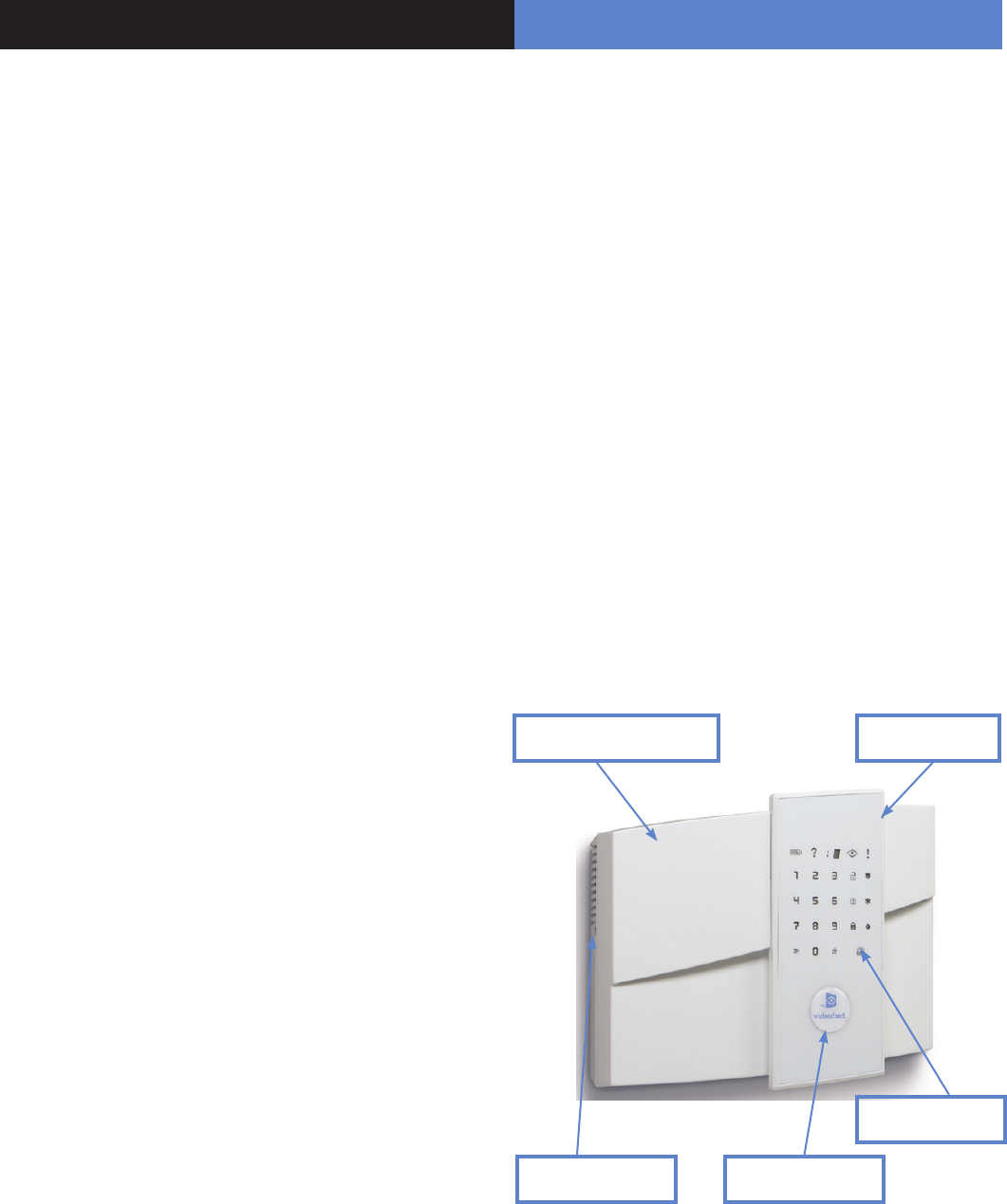
Siren and loud-speaker Microphone
Touch-sensitive
keypad
Locking screw Badge reader
On a piece of paper :
• Name the 4 geographical zones
A geographical zone corresponds to a surface where all the
sensors are armed/disarmed together. A partial arming prole is
a combination of geographical zones which are either armed or
not. By using the examples below, you are going to meet most
of the requirements.
Area A magazine Area A person
1 ENTRY DELAY 1 ENTRY DELAY
2 MAGAZINE 2 RDC
3 STOCK 3 FLOOR or OFFICE
4 DISCOUNT 4 GARAGE
(The1st geographical zone is inevitably delayed)
• Name the devices
Be as explicite as possible because in case of intrusion, it is this
device’s name that will display on the keypad and transmit to the
monitoring station. Example : CAM HALL ENTRANCE (for a
camera at the entrance).
• Allocate a geographical zone (from 1 to 4) to each
device.
1. Preparation before programming
2. The golden rules
1 The area 1 is always delayed.
2 Never place the panel near an electric switchboard :
there is possible interference with the radio and GPRS
modem.
3 Place the alarm panel at the most central location of the
site to be protected (also garantees a better propagation of
the radio).
4 When there is typing error, use the to delete the
incorrect character.
5 Never record the same device twice without
having rst deleted the device off of the panel.
6 Record a maximum of 19 devices of any kinds, without
distinction (initial keypad included).
7 Respect the installation height (under device) of
PIR : 2m10 to 2m35, cameras MotionViewer : 2m10 to
2m35 (ideally in an unobstructed angle)
8 Respect the installation height (under device) of
MotionViewer and PIR pet immune : 2m10.
9 Installation height for external DCV cameras: 2m80 to 3m
using the MB ball-and-socket joint (optional) and angling
the camera at the target to be protected.
10 If you are using a remote keypad, don’t install it at the
beginning of the installation
Always clean the camera’s lens after installation
(with a clean and dry piece of cloth, without pressing
on the lens).
12 To change from Capital to lower case, rst press the ,
then change from small letter/capital letter with and vice-
versa.
13 Be careful when opening and closing the panel cover (its
components are fragile).
• Dene the partial arming proles (combinations of
areas, see paragraph 5 and the partial programs on page 7).
• Ask the end user to prepare his/her codes (18
maximum access codes with 4 to 6 numbers per code).
11
00
3
Videofied Security System Installation Manual
The keypad becomes inactive after 40 seconds of
inactivity, in order to make the display to reappear,
press on the [YES] key.
15 Use alkaline batteries for the panel and for the interior and
exterior sirens.
3. Installation and programming
2. The golden rules
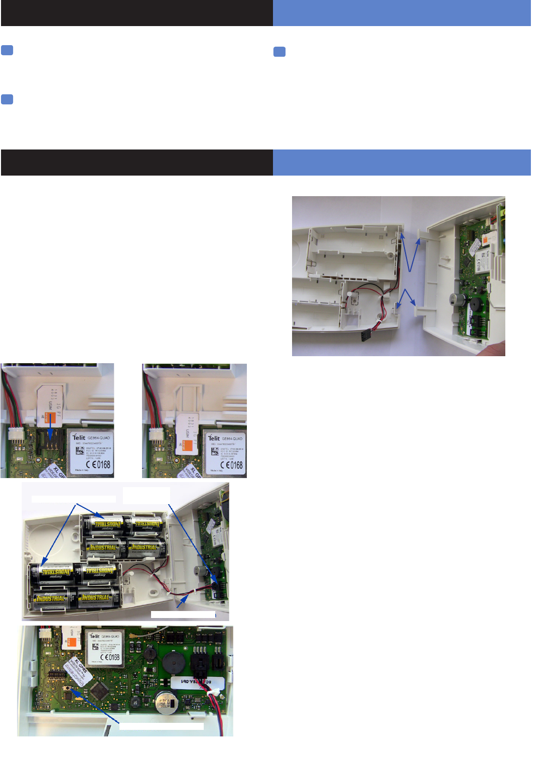
Open the packaging box and take out the cardboard divider
which serves as a gauge. Position it level against the attachment
tting, making sure the arrow is pointing upwards. Mark the 5
points, remove the gauge and pierce the 4 attachment holes
and the auto-protection hole. Attach the base. Insert the 8
alkaline batteries in their lodgings, paying attention to the correct
alignment of the positive and negative charges.
Before removing the front side of the packaging box, insert the
SIM card (voice/data or GSM/GPRS) as illustrated in gures 1
and 2.
Assemble the front side with the base by positioning the hinges
on the base.
3.1 Initialize the panel
• Insert the power cable into the power connection (the panel
emits a beep) and the keypad lights up and ashes.
• Hold down the PROGRAM BUTTON on the panel for 10
seconds untiil the keypad beeps again and lights up all the keys
of the panel keypad.
• Briey press the PROGRAM BUTTON of the panel again to
switch to keypad registration mode.
3.2 Record the keypad (cf. Keypad installation
manual)
• Insert the 3 Lithium LS14500 batteries in the keypad.
• Do not x the keypad, it will help you in the recording and
setting of the devices.
• Simultaneously press on [CLR] and [ESC NO] buttons on
the keypad, until the keypad’s indicator ashes and then release.
3.3 Close the panel cover
• Screw in the screw on the left of the box.
16 The ITRA110/600 and DCVA200/600/700 (devices
with pet immune) should never be placed
in stairs, or near stairs. (Risk of untimely triggerings).
14
Figure 1 Figure 2
Base Hinges
PROGRAM Button
Alkaline batteries
Power
connection
Power cable
Display of the keypad
3. Installation and programming
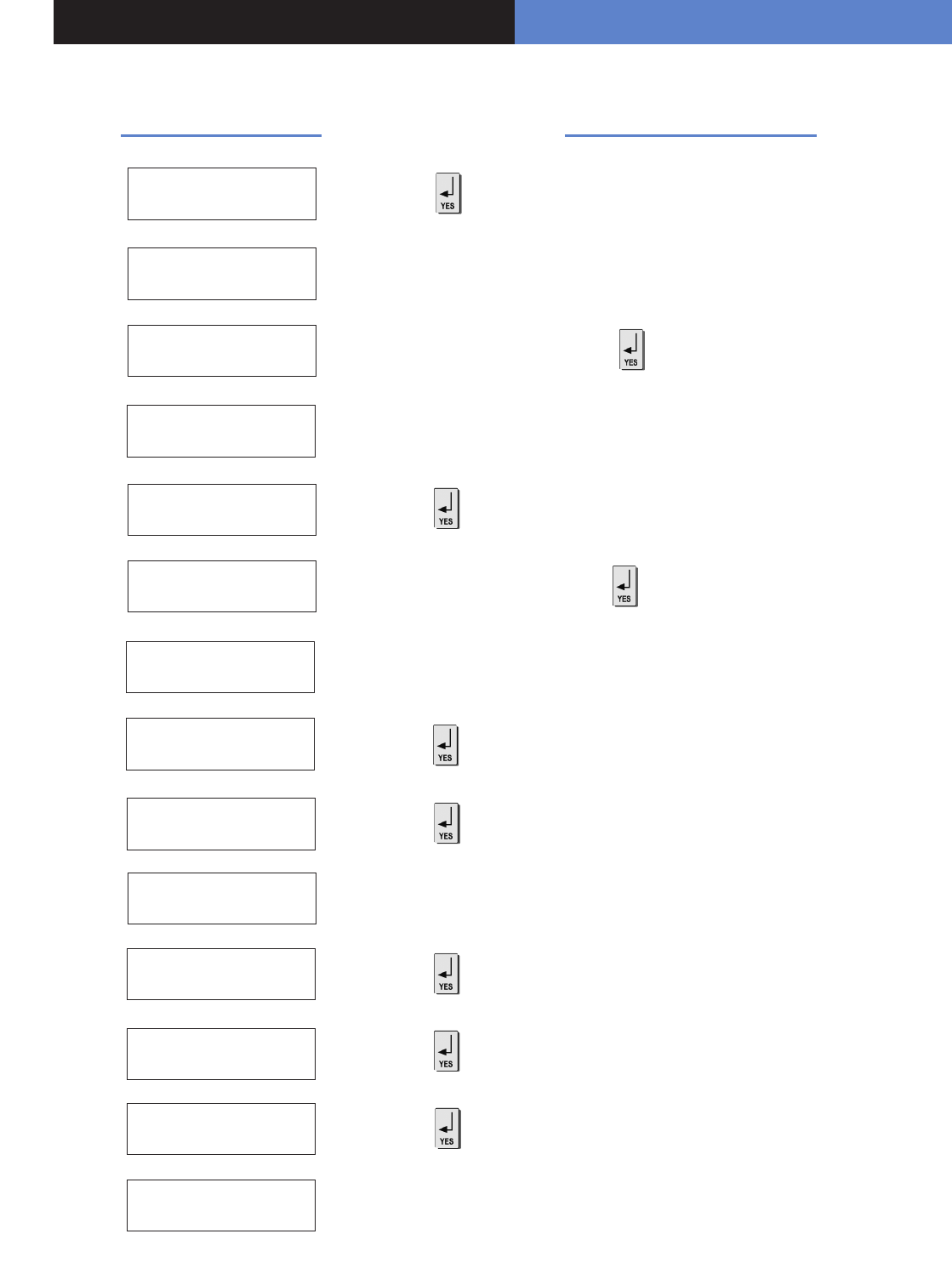
Actions and commentaries
KEYPAD 1
RECORDED
RADIO RANGE
TEST ?
RADIO RANGE
x/9
RADIO RANGE
9/9
RADIO RANGE
TEST ?
ENTER THE
INSTALLER CODE
4 TO 6 DIGITS
THEN YES
INSTALLER CODE :
CODE NAME :
ADJUSTING
TIME AND DATE
DATE (Year) :
00/ /
CONNECTED TO
MONITOR STATION?
Do the same for the Month, the Day, the Time and the Minutes.
Wait
Use direction arrows right or left to increase the
numbers and the [YES] key to validate the value and move to the next.
Naming the code + (Becareful, some NAMES correspond to pre-
programming of key accounts. (In case of incorrect setting, please contact
your technical department).
Installer code + , then conrm : Code +
Wait
Wait
Wait for 10s in order to obtain the rst stable value
Verify the range : A regular ashing or a
value of 2/5 or better indicates a sufcient
RF radio.
In order to stop the test.
< - LANGUAGE - >
ENGLISH to select the language.
00
5
Videofied Security System Installation Manual
to modify the value +
to modify the value +
Keypad Programming
3. Installation and programming
Display of the keypad Actions and commentaries
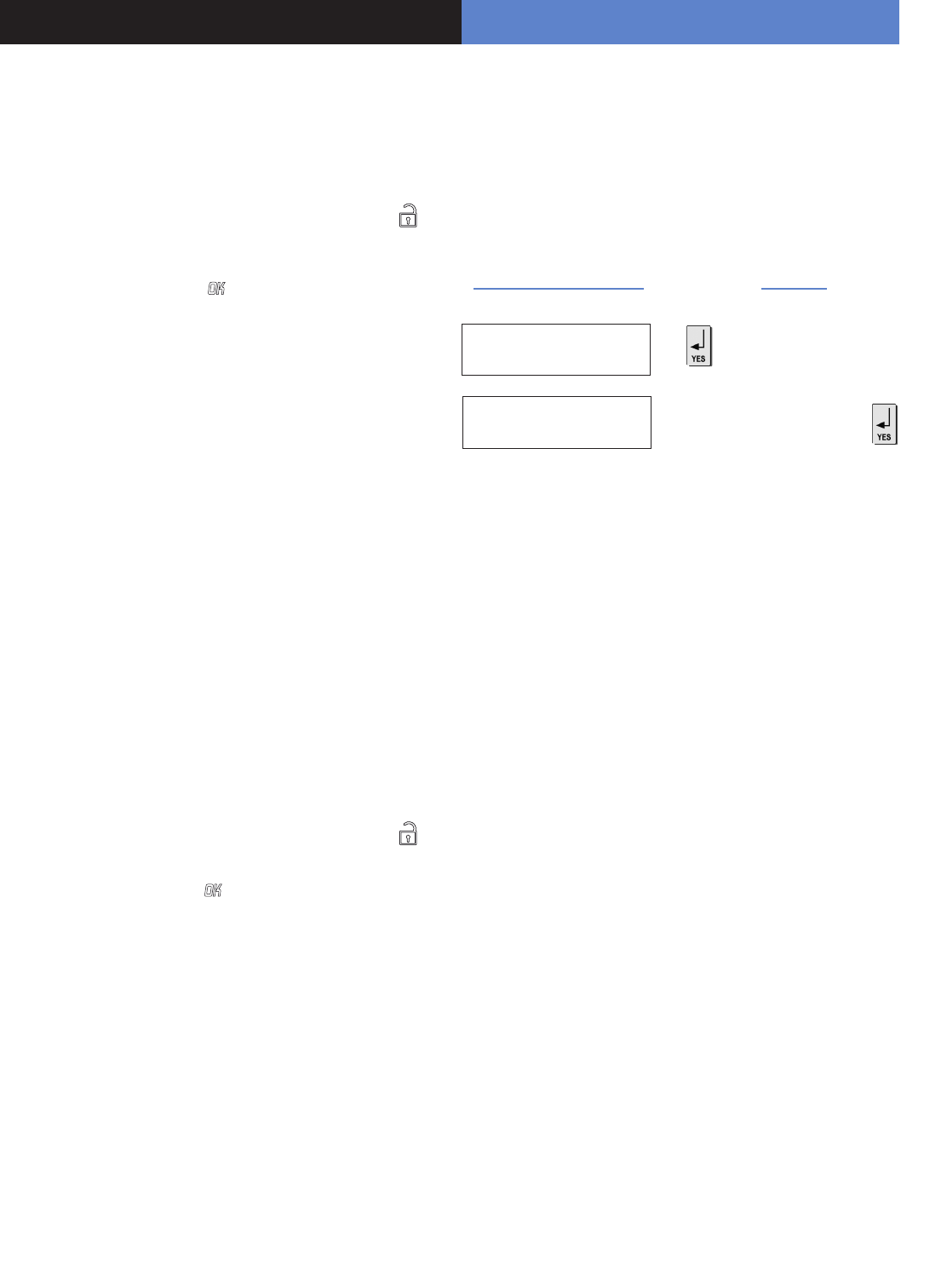
ACCOUNT NUMBER :
PERIODIC TEST
PERIODIC TEST :
24 HOURS
TEST HOUR :
00
Enter the Transmittor code +
CODE/STATE
MODIFICATION ?
ENTER
YOUR I.D. : Wait
or (to modify the event transmission status,and the on/off
controls, refer to Chapter 6.Details on the alarm codes menu, page 10).
to increase hours + , and do the same for minutes.
to change the period +
NAME OR ADDRESS
NAME OR ADDRESS
ENTRY COMPLETE
AREA
CONFIGURATION
AREA NAME 1 :
EXIT DELAY :
45 sec
Enter the name of the geographic area 1 + .
Do the same for other areas, turn to if need be to paragraph 1
“1.Preparation before programming”, page 2.
Wait
Enter “name” or “address” + (Name of the client, informative and
optional data only).
ENTRY DELAY :
15 sec
GPRS
PARAMETERS ?
3. Installation and programming
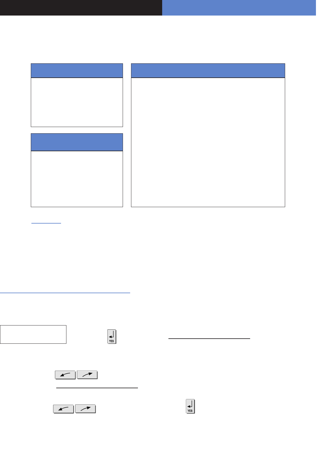
Display of the keypad Actions and commentaries
By default your GPRS panel has parameters of the ORANGE operator. It is necessary to modify the 3 parameters
that characterise the connection to another operator (SFR or BOUYGUES, WYLESS, T-MOBILE, ATT...).
Remark : GPRS Parameters is Case Sensitive ! (use the M/m key of the keypad to change Capital /Small letters).
Be careful : Use arrows to change
from one parameter to the other.
Press on the [YES] key only when
you want to modify a parameter!
(The APN is given by your operator. These parameters are likely to change following the
SIM card used. Ask your operator.)
APN CODE
internet-entrepr
USER NAME
orange
PASSWORD
orange
IP1 ADRESS
0.0.0.0
DOMAIN NAME 1
PORT 1
888
GPRS
PARAMETERS ? to exit the menu.
TEST IN PROGRESS
END = YES
GPRS LEVEL
5/5 It is not advisable to install a panel whose level is inferior to 3/5.
Wait (this could last for 3 minutes) for the result of the test which can be :
- a level between 1/5 and 5/5
- an error code (in this case, call you technical support)
PRESS PROGRAM
BUTTON OF DEVICE
Record your devices : (please refer to installation data sheets of each
device).
GPRS LEVEL Press the and wait for the reception level. Do not remove the SIM
card during the test!
You are going to enter various parameters depending on which GPRS
operator’s SIM card you have.
The rst parameter is the APN code.
By default, the standard public access parameters are those of Orange.
Press [YES] to modify the value or the right arrow to move on to the next
parameter.
Second parameter: USERNAME
Third parameter: PASSWORD
The IP1 address or the domain name and Port 1 are provided by the
monitoring station. Likewise for the IP2 address and the IP TMT address if
applicable. Once the values have been established,
Press the to return to the PARAMETRES GPRS menu.
ORANGE SFR BOUYGUES ........................
APN internet-entreprise m2minternet a2bouygtel.com ........................
USER orange Open eld Open eld ........................
PASS orange Open eld Open eld ........................
00
7
Videofied Security System Installation Manual
4. End of installation
You have recorded and x all the devices, record the remote controls, then with the question :
Display of the keypad Actions and commentaries
ENTERING A NEW
DEVICE ?
OPERATION
COMPLETED ?
SYSTEM CHECK
IN PROGRESS
INSTALATION
SUCCESSFUL !
(Close the cover of the panel)
All that remains is to program the user
codes, Partial arming modes and eventually
the Intercom time (at 180 seconds).
5. How to...
5.1 Program partial mode
With the direction arrows go to the menu
CONFIGURATION (niv 4) -> ALARM MODES
PROGRAMMABLES -> FULLY ARMED
Then use the direction arrows to select the relevant arming
mode and the [YES] key to modify it.
There are three possible arming modes.
NORMAL MODE is the general arming mode, set using a badge
or with a user code and keys or .
MODE SPECIAL1 is a partial mode activated by entering a user
code and pressing the . This mode is also accessible on a
CMA keypad via the and via an RC remote control via
the .
SPECIAL2 MODE is not accessible on the keypad of an XL
panel. It is available on a CMA keypad via the and via an
RC remote control via the .
For each arming mode, it is possible to specify how each of the
4 zones will be armed and how the sound alert will be made.
Areas : 1 2 3 4 Each time you press on the number
of the area it modies the correspondance.
State : A A A A Situated below. Validation at the end, the
[YES] key.
A Armed Siren Immediate triggering
of all sirens
DDisarmed Delay
beeps
Entry/Exit delay
beeps, then triggering
of the sirens
P
Perimeter
(all the opening
contacts)
Silent Without siren
without beeps
E
External (opening
contacts protecting an
exterior access)
Without
siren
Beeps on the
keypad only
PERIMETRIE MODE is not accessible on the XL keypad. It is
only availble on the CMA deported keypad by + user
code + [YES].
You can now close the XL panel, making sure you fully tighten the screw on the left-hand side.
00
5. How to ...
Display of the keypad Actions and commentaries
ACCESS LEVEL
LEVEL : 3 => 4 Use the right arrow to increment the level to 4.
ACCESS LEVEL
3
BADGE OR CODE Enter the installer code +
< = = = = XX = = = = > You can remove the keypad batteries.
DELATE
KEYPAD
ACCESS LEVEL
4
GENERAL
PARAMETERS
AREAS AND
DEVICES
DEVICES
Use the right arrow to go to the CONFIGURATION menu.
ADD A NEW
DEVICE to go to the DEVICE CONFIGURATION menu.
Press the left arrow twice to go to the ZONES AND DEVICES menu.
BADGE OR CODE Enter the installer code +
DEVICE
CONFIGURATION
Z1:KEYPAD
KEYPAD 1 (If necessary, use the direction arrows to select the keypad).
5.2 Delete the keypad
CONFIGURATION
00
Videofied Security System Installation Manual 9
5. How to ...
5.3 Register again a CMA keypad on an XL panel
without opening the cover
Activate the touch-sensitive keypad by placing your hand over it.
Enter in special mode by pressing for 3 seconds on the
and the numerical keypad starts to ash.
Type the code 000000 then to switch the XL panel
in keypad registration mode. On the keypad:
- Insert the 3 Lithium LS14500 batteries.
- Simultaneously press [CLR] and [ESC NO] on the keypad
untiil the indiicator light on the panel ashes and then release.
It is possible to activate or disactivate the ashing green battery
symbol.
Bear in mind that when this symbol is activated, the product has
less battery life and the batteries will have to be changed within
4 years.
Enter in special mode by pressing for 3 seconds on the
and the numerical keypad starts to ash.
Type the code 000100 then the digital keypad will
remain illuminated while the green battery symbol starts to ash
with the number 0 or 1 on the 7-segment digit.
The number shown is an indication of the display conguration
for the battery symbol (0 for disactivated, 1 for activated).
5.4 Activate or disactivate the flashing green
battery symbol
5.5 Open the cover of an installed XL panel
Unscrew the screw on the left-hand side of the panel and
separate the panel of the base.
KEYPAD 1
RECORDED
INSTALLATION CODE Enter the installer code +
Display of the keypad Actions
5.6 IP TMT Configuration
You need a computer connected to the network IP, congured
either on a xed address IP with the opened port 888 is needed,
or on a name of domain with the opened port 888.
About the programming of the panel, it is necessary either to
inform on the IP TMT your xed IP, or on DOMAIN NAME your
domain name.
The computer connected on your network has to have the
software Fontel TMT installed and parametrized.
The connection by seizing 999999 + [OK] on the panel XL,
either on the keypad CMA (if it is on the site).
In Frontel TMT make: File / open, a window opens with the
account N ° (code transmitter).
Click above, validate the request of remote maintenance
by clicking on OK, then to make an import to get back the
programming of the site.
6. Details of the menu : ALARM CODE
Signalling events by default (except if you are
using pre programming)
By default these events are transmited:
DEVICE (intrusions)
ALERT (button)
TAMPER
PERIODIC TEST
By default are not transmited:
INITIALIZATION
PANEL BATTERIES (low panel batteries)
AC POWER (panel power off)
PHONELINE FAULT (telephone)
DEVICE BATT. (low batteries devices)
RADIO JAMMING (radio jamming)
SUPERVISION (default supervision)
WRONG CODES (when entering 5 false codes/badges)
DURESS CODE (panic button)
ALARM MEMORY (old memory overwritten)
ARM/DISARM (open/close)
There are the 3 transmission
states:
ALARM, which can be heard :
when it appears
ALARM / END, which can be
heard : when it appears and disap-
pears
NOT TRANSMITTED
Examples :
- If one wishes to recall events of ARMING/DISARMING (operate/stop), you will have to modify the
conguration of events ARMING/DISARMING to ALARM / END.
- If you wish to recall the false codes information, you will have to modify the conguration of events
WRONG CODES on the state ALARM.
How to modify the transmission state of events?
2 possible solutions:
• At installation, just after having validated the hour of the cyclic test, the keypad requests :
CODE/STATE
MODIFICATION ?
• After the initial installation, by using the keypad :
With direction arrows go to the menu CONFIGURATION (level 4) -> CONFIGURATION MONITOR. STATION
-> ALARM CODES -> TRANS. STATE MODIFICATION
Then:
With direction arrows Select the event to transmit, make then modify the transmission state with arrows
and revalidate with the [YES] key. Renew the operation for each event which you wish to modify the transmission regulations.
Press on the to access the menu TRANS. STATE MODIFICATION
In all cases, be sure to check that the conguration of your XL
system is suitable for your needs.
7. Table of GPRS error code correspondances
GPRS LEVEL :
ERROR XXX
Start the test again after rst error.
In case of GPRS error, we recommend you continue installation by
recording of detectors and devices and then come back to the GPRS level
test.
During the GPRS level test, if there is an error an associated code appears in place of the the GPRS level.
Codes Errors
03 ou 04 No network coverage or no SIM card GPRS data
010 SIM non inserted
011 Code PIN necessary
-> The PIN code must be disactivated
012 Code PUK necessary, SIM card blocked
013 Default SIM card
014 SIM card busy
015 Error on SIM
016 Incorrect password
017 SIM PIN2 necessary
-> The PIN code must be disactivated
018 SIM PUK2 necessary
022 SIM not found
030 No network coverage or no SIM card GPRS data
040 : 047 SIM card non inappropriate or blocked
-> Unlock with PUK code
149 Authentication error
-> Incorrect Network problem or parameters (APN, USER, ...)
107 Service data GPRS non authorised
-> SIM card unsuitable
Table of correspondance error codes
!!! The PIN code of the SIM cards must either be disactivated or be 0000 !!!
Codes Errors
043 Typographical error in the APN Code username or password
003 SIM card not detected/no inserted
132 SIM card not activated
030 No GPRS signal
915 MHz codes
11
00
EMEA SALES
23, avenue du Général Leclerc
92340 BOURG-LA-REINE
FRANCE
Hot line : +33 (0)820 846 620
Fax : +33 (0)3 90 20 66 36
© 2009 RSI Video Technologies Videoed® is a Registered Trademark of RSI Video Technologies.
Specications subject to change without notice.
www.videofied.com
North American Headquarters
4455 White Bear Parkway, Suite 700
White Bear Lake, MN 55110
USA
Hot Line : 877-206-5800
Fax : 651-762-4693
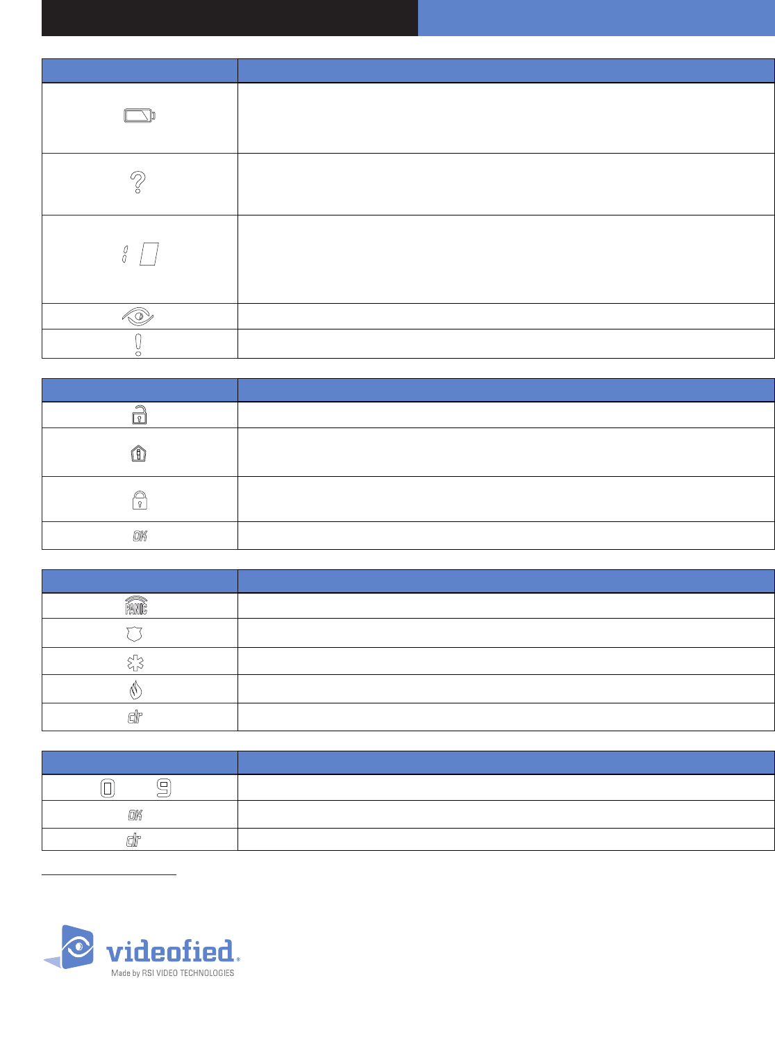
8. Numeric Keypad
Symbols Explanations
D
• When the indicator light is green: indicates that all the batteries (panel + peripheral) are OK
• When the indicator light is red: indicates that there is a battery fault either on the panel or on
a peripheral device (the N° will be indicated on the display)
P
• During arming: signals the detection of a peripheral device in a zone not on a time setting
• Not armed: signals the auto-protection of a peripheral device (the N° will be indicated on
the display)
Used in order to identify:
• N° of the peripheral device (0 for the panel and 1 to 19 for the peripheral devices) in the vent
of auto-protection, intrusion, low battery, etc.
• Incorrect authentication (‘C’ for wrong code)
Indicates that there has been an intrusion
Indicates any other fault (radio interference, ect.)
Symbols Explanations
DUsed to disarm the system (after entering the code)
P• Enables arming in partial mode (after entering the code)
• Flashes when the system is partially armed
• Enables arming in total mode (after entering the code)
• Flashes when the system is totally armed
Enables arming in total mode (after entering the code)
Symbols Explanations
DKey to be held down for 3 seconds to activate panic buttons
POnce it lights up, pressing this key will send a police call through to the monitoring station
Once it lights up, pressing this key will send an emergency call through to the operators
Once it lights up, pressing this key will send an emergency call through to the operators
This key allows you to cancel the activation of the panic buttons
Symbols Explanations
à DKeys for entering user codes
PKey for conrming code
Delete key in case off error
Using the numeric keypad: to conserve the batteries, the numerical keypad automatically turns off after a few seconds of not being used. Before entering
the code, you need to reactivate it. To do so, place your hand at over the numeric keypad, it will light up and then you can use it.