Railhead WING Wing Walker RF-Host Wireless alarm control box User Manual WingWalker G
Railhead Corporation Wing Walker RF-Host Wireless alarm control box WingWalker G
Railhead >
user manual
TEL: 708-844-5500 FAX:708 - 844-5559
RailheadCorporation
12549S.LaramieAvenueAlsip,IL60803,USA
WingWalker‐GUsermanual
1. Overview
WingWalker‐GWirelessalarmsystem,whichiscomposedofSLB41standardbaton,SLB41‐RFradiocommandbar,
GST16‐RFwarninglampandRF‐Hostwirelessalarmcontrolbox.Whentheradiobaton(SLB41‐RF)totriggerthealarm,
wirelesstransmittingalarminformation,wirelessalarmcontrolbox(RF‐Host)toreceivethisinformation,issuedsound
andvibrationalarm,simultaneouslybywirelessalarmcontrolboxstartGST16‐RFwarninglamp.Alarmstatuscanonly
beremovedbytheoperatorofthealarmcontrolbox.
ThewirelesspartofthesystemworksintheISMband,themaximumtransmitpowerislessthan0dBm,meetthe
relevantprovisionsoftheISMband.
Host(IDcode)isunique,andcanbeprogrammedtoensurethatthedifferentalarmsystemsdonotinterferewitheach
other.
2. WirelessParameter
3. detaileddescription
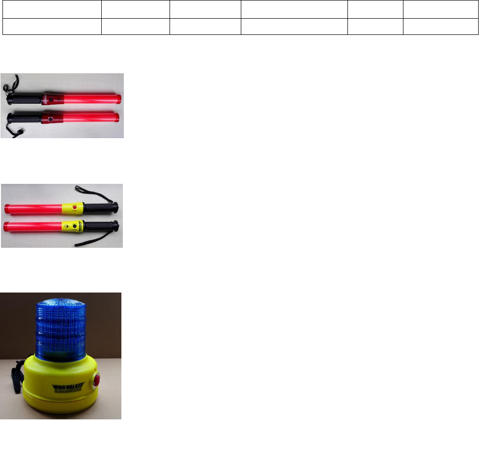
1. SLB41Standardcommandbar
PowersupplyusingtwoAM2SIZECLR14alkalinebatteries.
Theblackswitchcontrolsthelightingandextinguishingofthebaton,anddoesnot
have the function of wireless transmitting and alarming. Two black switching
functionsarethesame,arecontrolledbyLED(red)lightup/out.
Thecolorofthecircuitboxisred.
2. SLB41‐RFRadiocommandbar
PowersupplyusingtwoAM2SIZECLR14alkalinebatteries.
Blackswitchcontrolsthelight/offofthebaton
Whentheredbuttonispressed,thebatonislit,andthealarm information is
transmitted.
Thecolorofthecircuitboxislemonyellow.
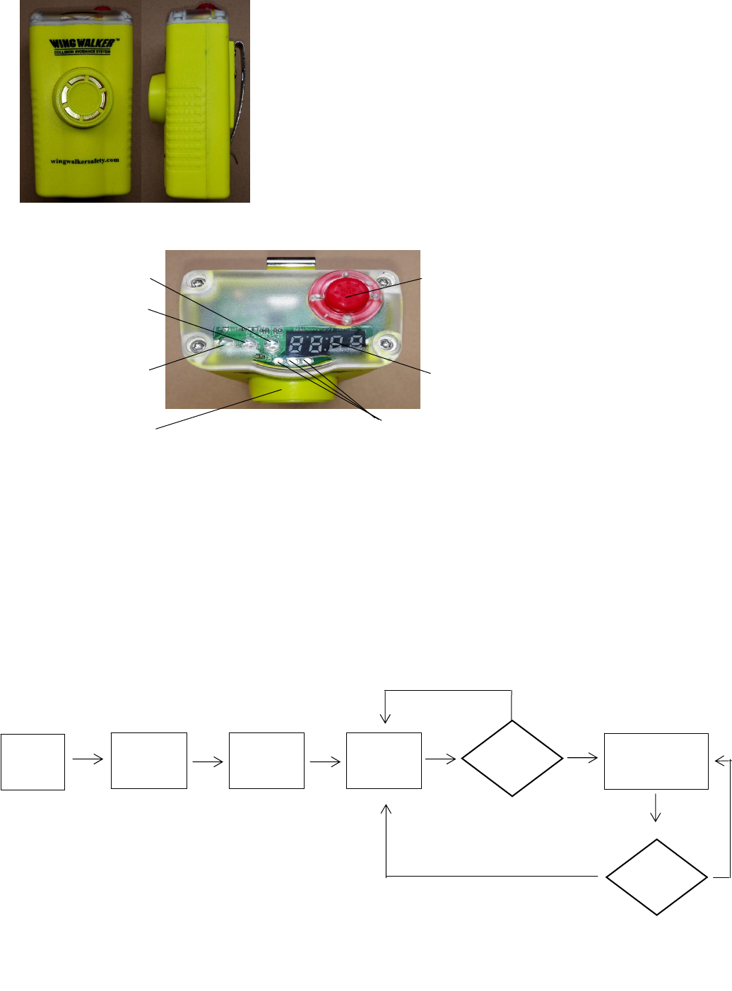
3. GST16‐RFWarninglight
Use two AM1 SIZE D LR20 alkaline battery power supply.
Turn on the power switch, the blue LED flashed out and blue shade of red
indicator light flashes, said GST16-RF enter standby state (wait RF-Host
flashing lights control information), when received RF-Host alarm
information, blue dual LED flash explosion; if RF-Host stop sending flash
control information, GST6-RF turn to standby, continue to control
information to wait to RF-Host flash.
Built in two switch, select working mode: normal / on code.
3 hole magnetic suction bottom cover.
CenterFrequency Modulation AirDatarate FrequencyDeviation Antenna Power
2.440GHz GFSK 250Kbps 1MHz 1.5dB ‐5dBm(Max)
TEL: 708-844-5500 FAX:708 - 844-5559
4. RF‐HostWirelessalarmcontrolbox
Builtinpolymerlithiumbattery(11.1V),youcanuserechargeable
batteries.
LEDdigitaldisplaytube,usedtodisplayIDHost.
Thereare3powerindicatorLED,usedtoindicatethequantityofelectricity.
Builtinbuzzerandvibrationmotor.
Equippedwithsteelclip.
Boot,thefirstimplementationoftheself‐testprocess,andthenenterthe
codefunction,afterthecompletionoftheabovetwostepsintothenormal
standby state, waiting for the SLB‐RF radio command bar sent alarm
information.
RF‐HostPaneldescription:
①Power:RF‐HostPoweron/off。
Ifyoucancelthealarm,restartyoucan.
②LEDDigitaldisplaytube.:DisplyHostID。
③Batteryindicator:displaypowerlithiumbattery.
3LEDlight:fullpower,2LEDlight:about50%oftheelectricity;1LEDlight:lowpower,needtocharge.
④BlueLED:heartbeatstatusindicator。
⑤Red/yellowLED:alarmindicationLED,
Whenanalarmoccurs,thered/yellowLEDflashesalternately.
RF‐HostWorkflowchart
Powerswitch
LEDDigitaldisplaytube
BatteryIndicator
REDLED
YELLOWLED
BLUELED
Buzzer
N
Turn
On
Self
checking
Pair
code
Standby Alarm?Alarm
processing to
Y
timing?
N
Y

TEL: 708-844-5500 FAX:708 - 844-5559
<RF‐HostSelfcheck>
Press the power button to start the alarm control box, RF-Host start self-test process: LED digital
display tube in order to display the numbers from 1 to 9, and the power indicator LED, red, yellow,
and blue LED turn the water lit and extinguished, the final buzzer sounded a short sound, vibration
motor about. After the above process, complete self inspection.
<RF‐HostPaircode>
RF-Host after the self-test, namely entered the state code: digital display display current host
ID, blue LED flash, while the emission wireless to code information, the process lasts for about 2
seconds, digital display tube is closed, the display. Toward the end of the status code. Into the normal
standby state, at this time, only the blue LED slow heartbeat flashing, waiting for the occurrence
of alarm events.
<RF‐HostAlarmprocessing>
When RF-Host receives the SLB41-RF to send the alarm information, LED digital display tube display
ID Host address, red, yellow LED alternating light, while the buzzer and vibration also synchronous
alternating action. Wireless flash control information to the GST6-RF, the GST16-RF began to flicker.
There are two ways to cancel the alarm state: A. to re open the power, you can reset the alarm state.
B. alarm state lasts about 1.5 minutes or so, you can automatically withdraw from the alarm state,
to return to the standby state.
5. chargingseat
RF‐Hostalarmcontrolboxforcharging,while2RF‐Hostcharging.
Incharge,theredindicatorlight;
Chargingcompletion,thegreenindicatorlight.
4. operationmethod
(1)blockdiagram
BlockdiagramoftheworkingstateofthecodeNormalworkingstatediagram
R
R
S
G

TEL: 708-844-5500 FAX:708 - 844-5559
FCC Statement
This equipment has been tested and found to comply with the limits for a Class B digital device, pursuant
to Part 15 of the FCC Rules. These limits are designed to provide reasonable protection against harmful
interference in a residential installation. This equipment generates uses and can radiate radio
frequency energy and, if not installed and used in accordance with the instructions, may cause harmful
interference to radio communications. However, there is no guarantee that interference will not occur
in a particular installation. If this equipment does cause harmful interference to radio or television
reception, which can be determined by turning the equipment off and on, the user is encouraged to try
to correct the interference by one or more of the following measures:
-- Reorient or relocate the receiving antenna.
-- Increase the separation between the equipment and receiver.
-- Connect the equipment into an outlet on a circuit different from that to which the receiver is
connected.
-- Consult the dealer or an experienced radio/TV technician for help.
This device complies with part 15 of the FCC Rules. Operation is subject to the following two
conditions:(1) This device may not cause harmful interference, and (2) this device must accept any
interference received, including interference that may cause undesired operation.
Changes or modifications not expressly approved by the party responsible for compliance could void
the user's authority to operate the equipment.