Rayence RY1417WHD Medical Image Processing Unit User Manual 1417WCC WGC
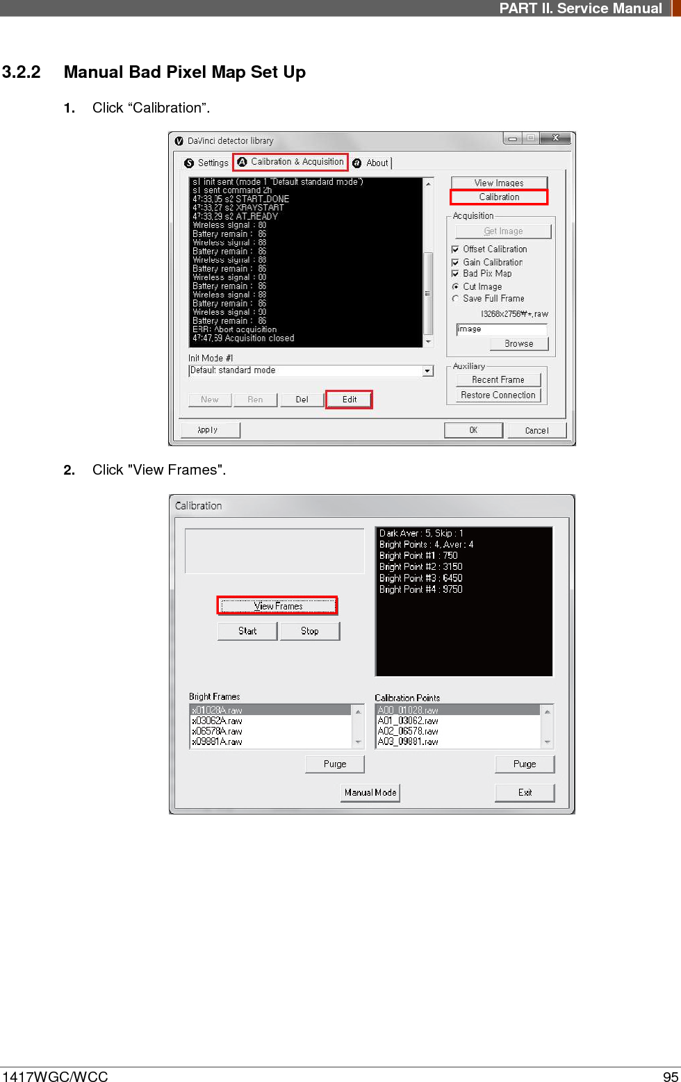
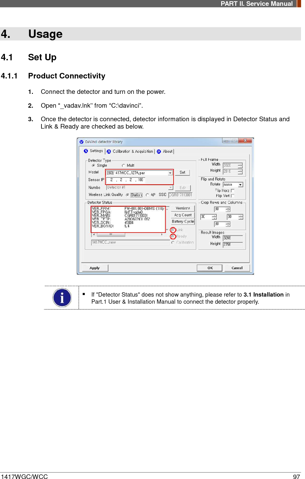
Rayence Co., Ltd. Medical Image Processing Unit 1417WCC WGC
UserManual.wiki
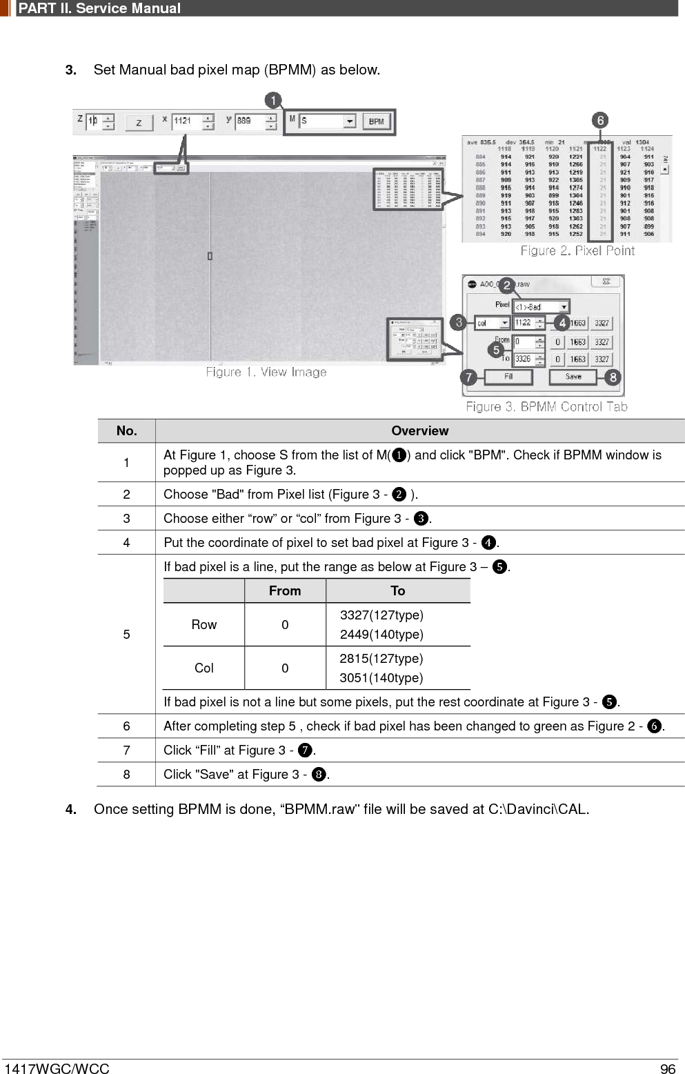
>
Rayence
>
RY1417WHD User Manual
User Manual
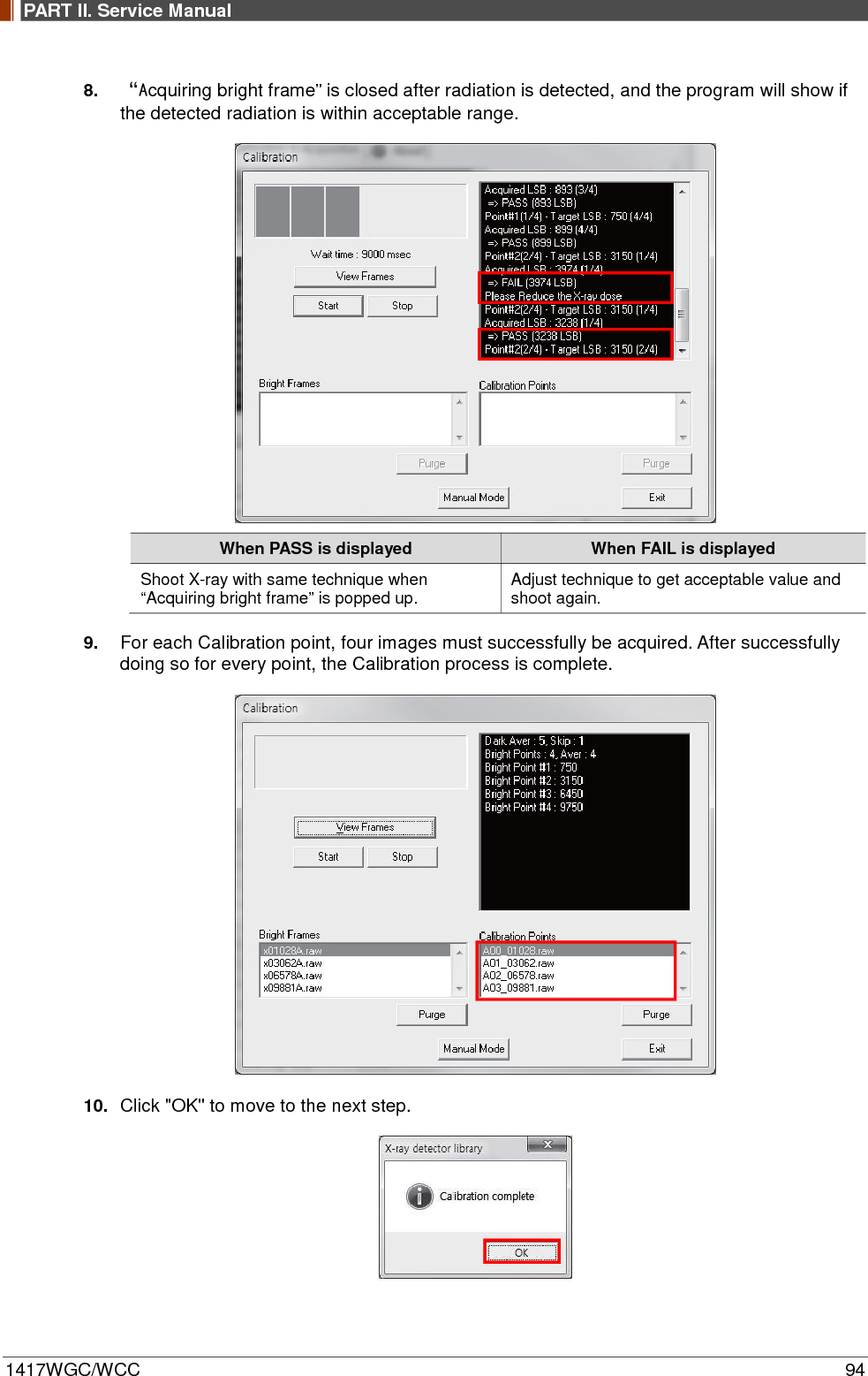
Navigation menu
Upload a User Manual
Namespaces
Wiki Guide
HTML
PDF
Info
Views
User Manual
Discussion / Help
Navigation

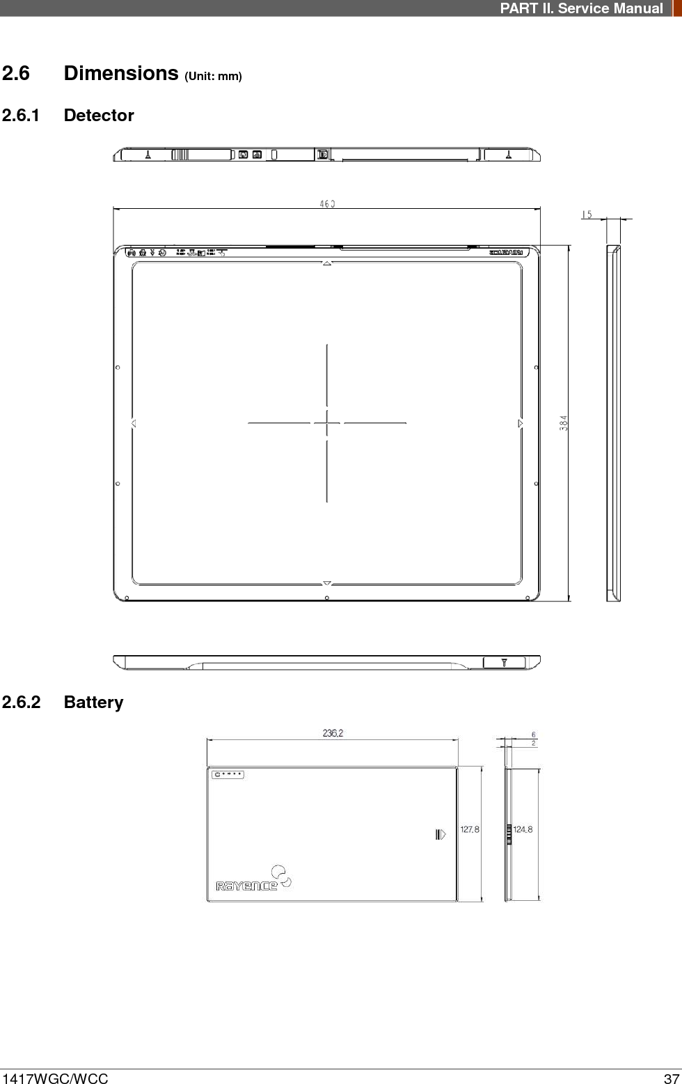
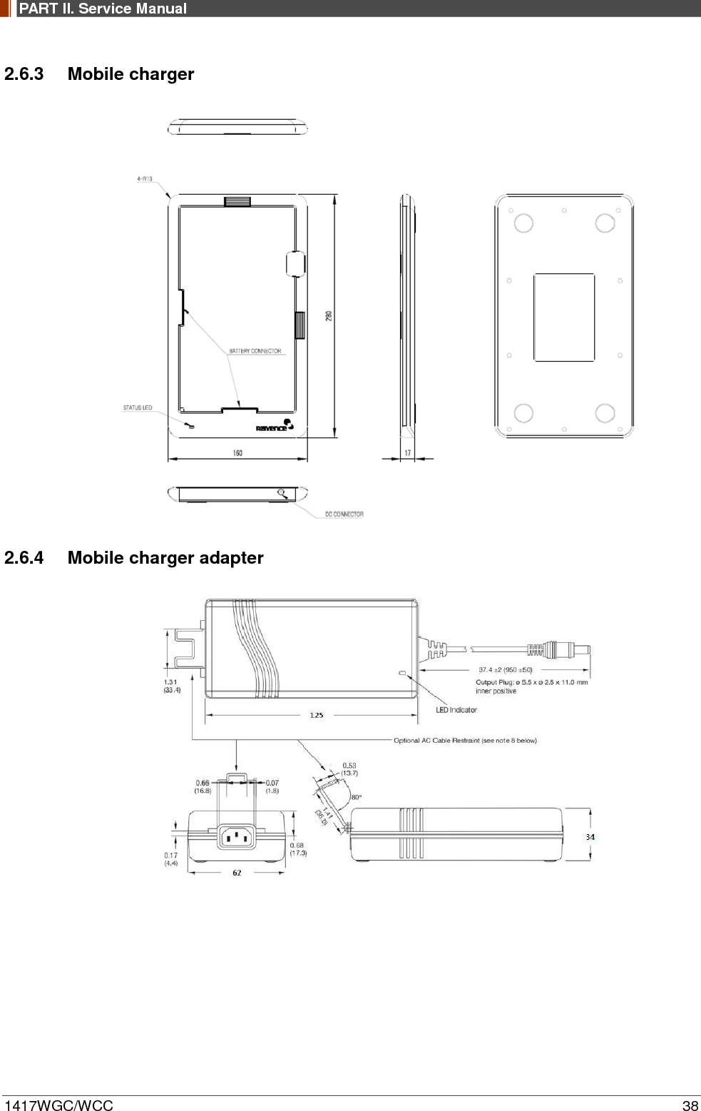
![PART II. Service Manual 1417WGC/WCC 33 Parameter Spec. Unit MIMO 2 X 2 Maximum wireless signal rate derived from IEEE standard specifications. Actual data throughput will vary. Network conditions and environmental factors, including volume of network traffic, building materials and construction, and network overhead, lower actual data throughput rate. Recommended Maximum operable distance : 10m (From the Access Point) Wireless Module and Wireless Antenna • Wireless antennas: The module adopts the latest 802.11n Dual-Band technology (2.4Ghz and 5Ghz). The transmitter of the module is powered by host equipment (Detector). The antennas are 2 printed-dipole antennas. 2.4.2 Battery [Model name: RB37WHA] Parameter Spec. Unit Size 236.2 x 127.8 x 6 mm Weight 0.3 Kg Input 12.6 VDC Output 11.1 VDC Cycle life Max. 500 cycles Operation temp. range 5~40 ℃ Charging time Typ. 3 hours Capacity Typ. 3400 mAh Operating time Typ. 4 hours 2.4.3 Mobile charger [Model name: RMC001A] Parameter Spec. Unit Dimension 280 X 160 X 17 mm Weight 0.3 Kg Input 18 VDC Output 12.6 VDC 2.4.4 Mobile charger Adaptor [Model name: AFM60US18] Parameter Spec. Unit Dimension 125 X 62 X 34 mm Weight 0.4 Kg Input 80-264VAC, 47~63Hz, 1.5A - Output 18VDC, Max 3.34A -](https://usermanual.wiki/Rayence/RY1417WHD/User-Guide-3524108-Page-33.png)
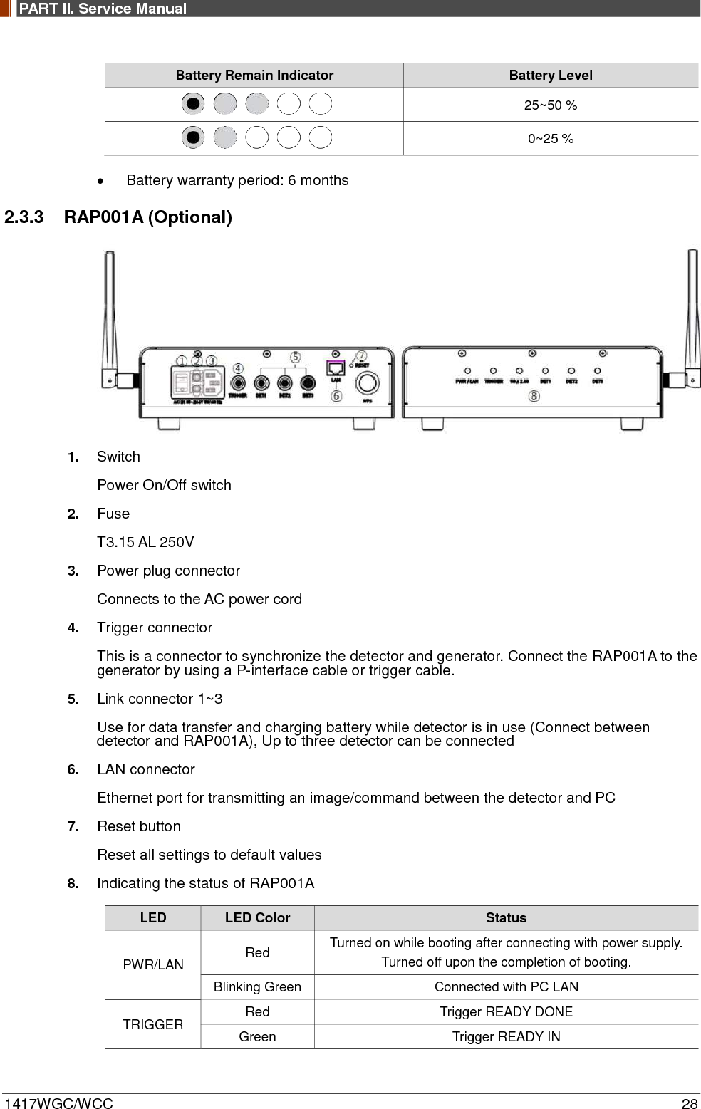
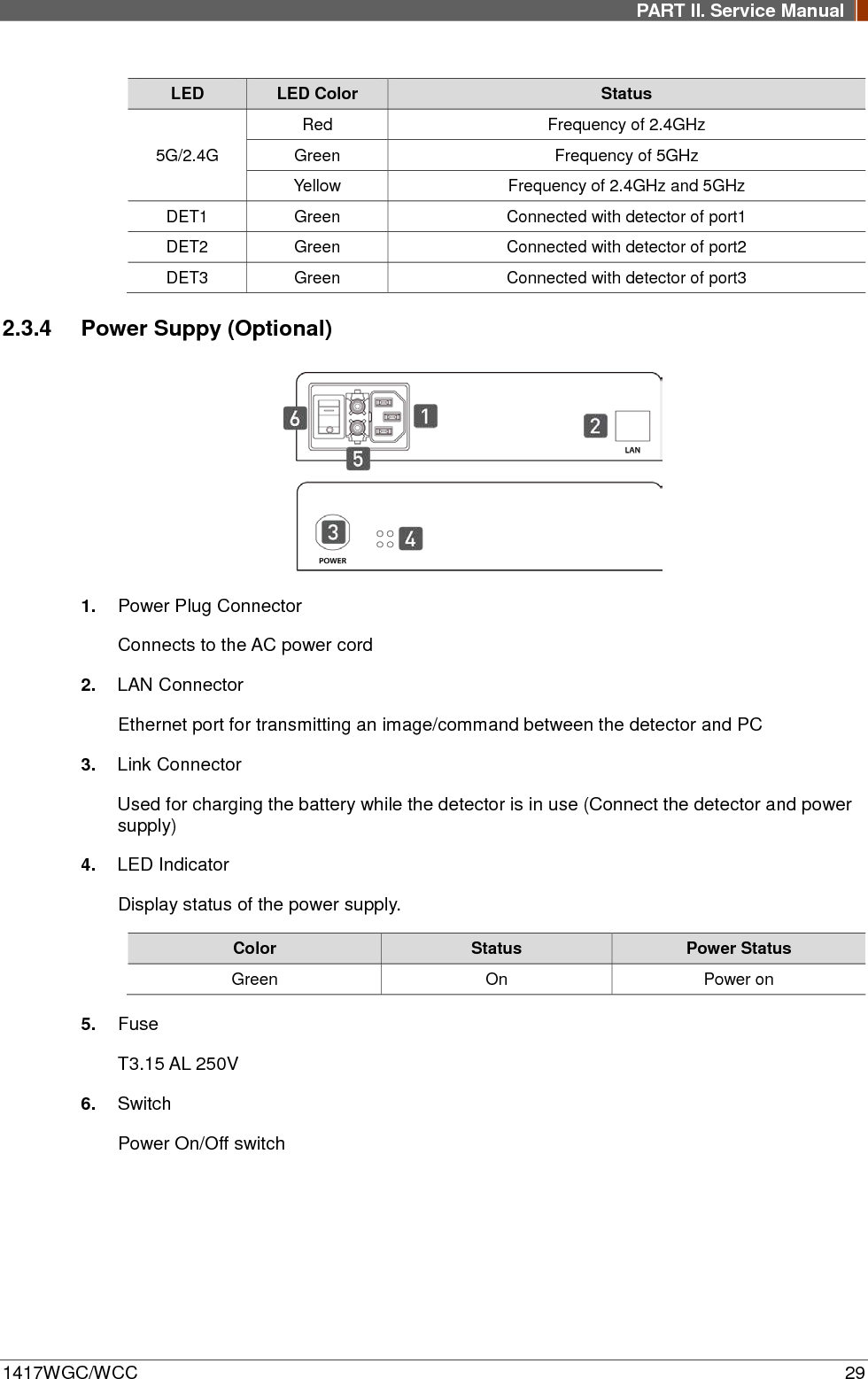
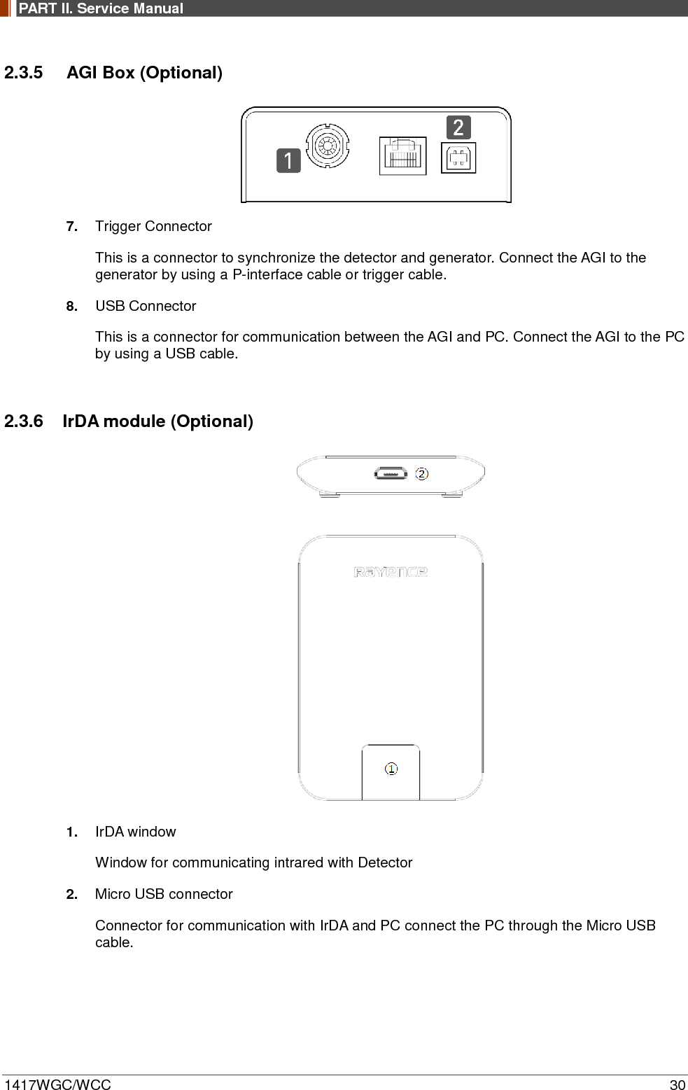
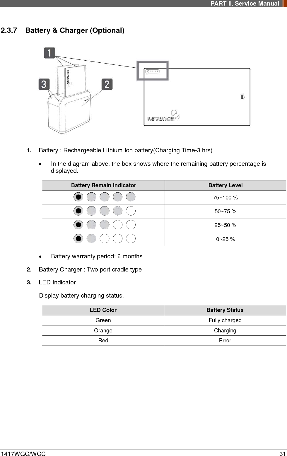
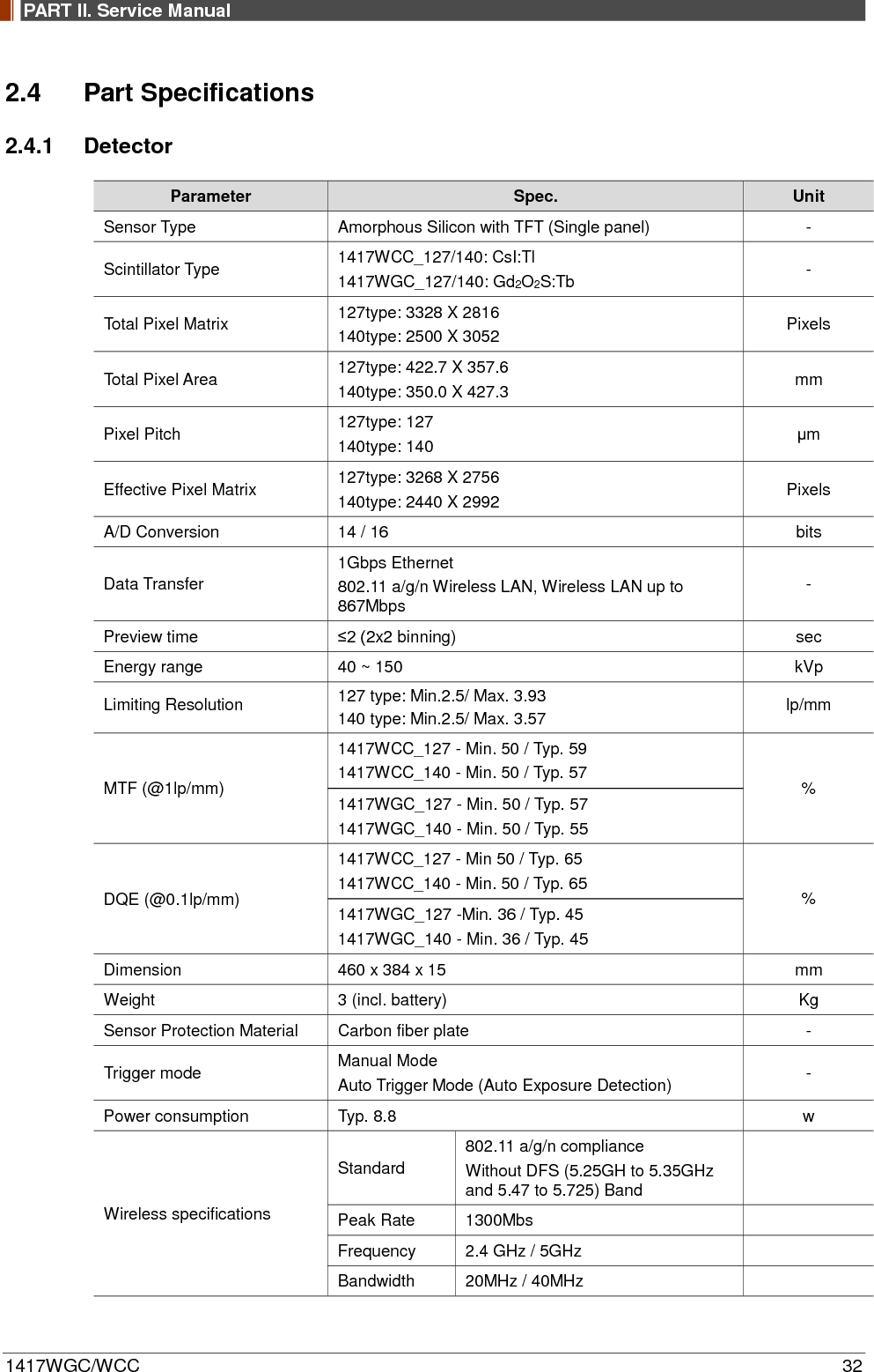
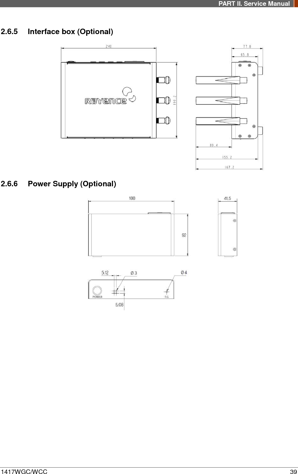
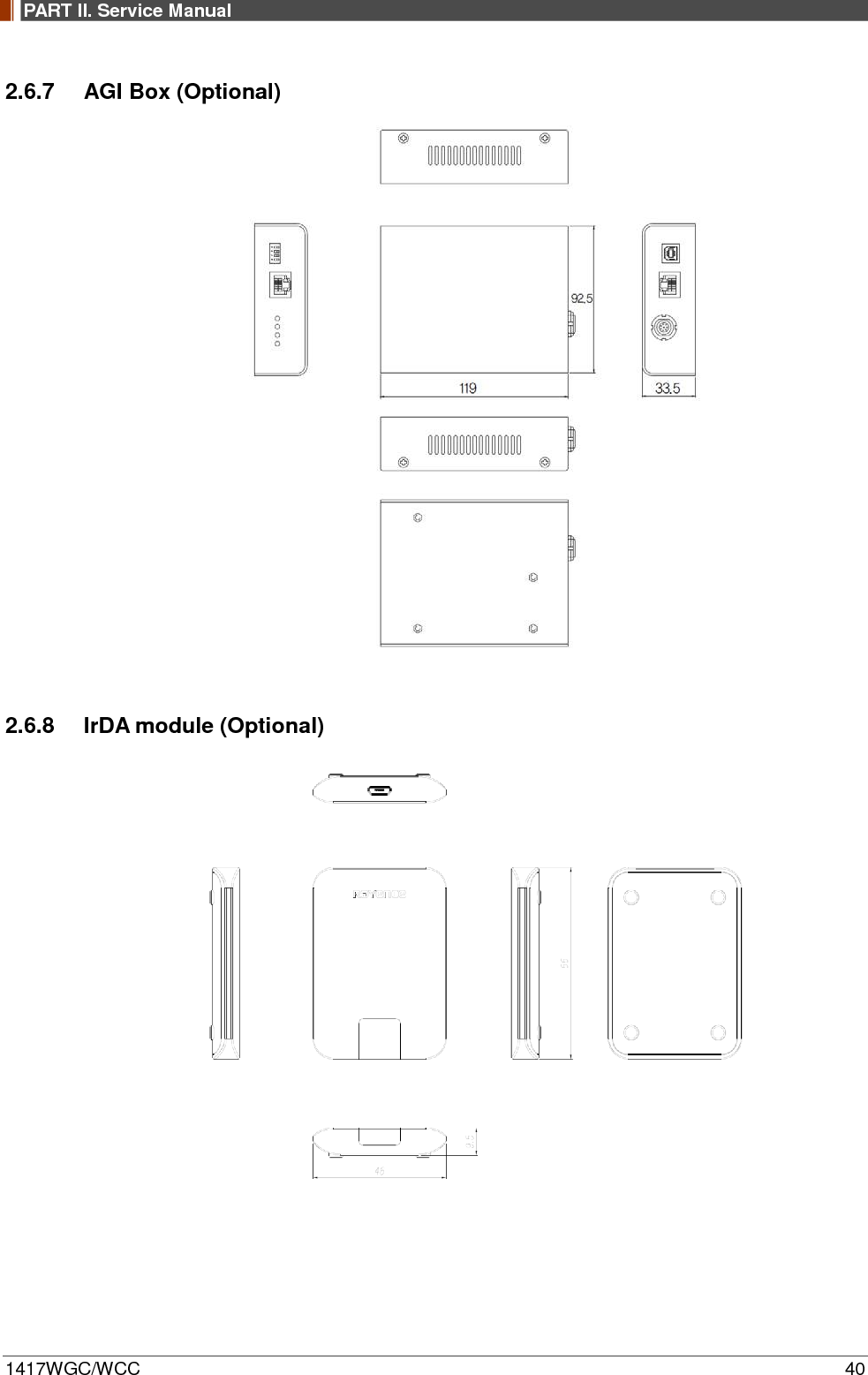
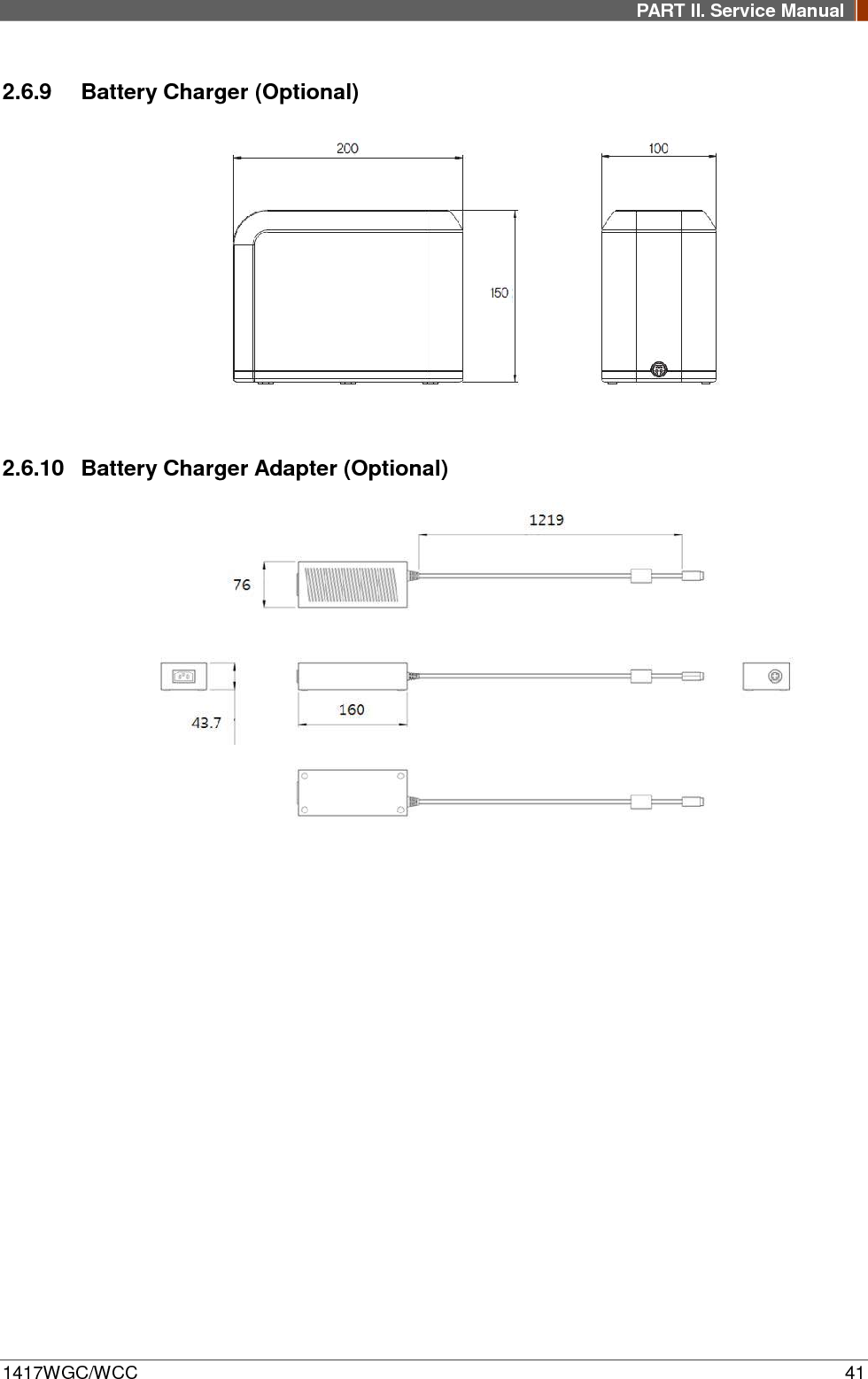
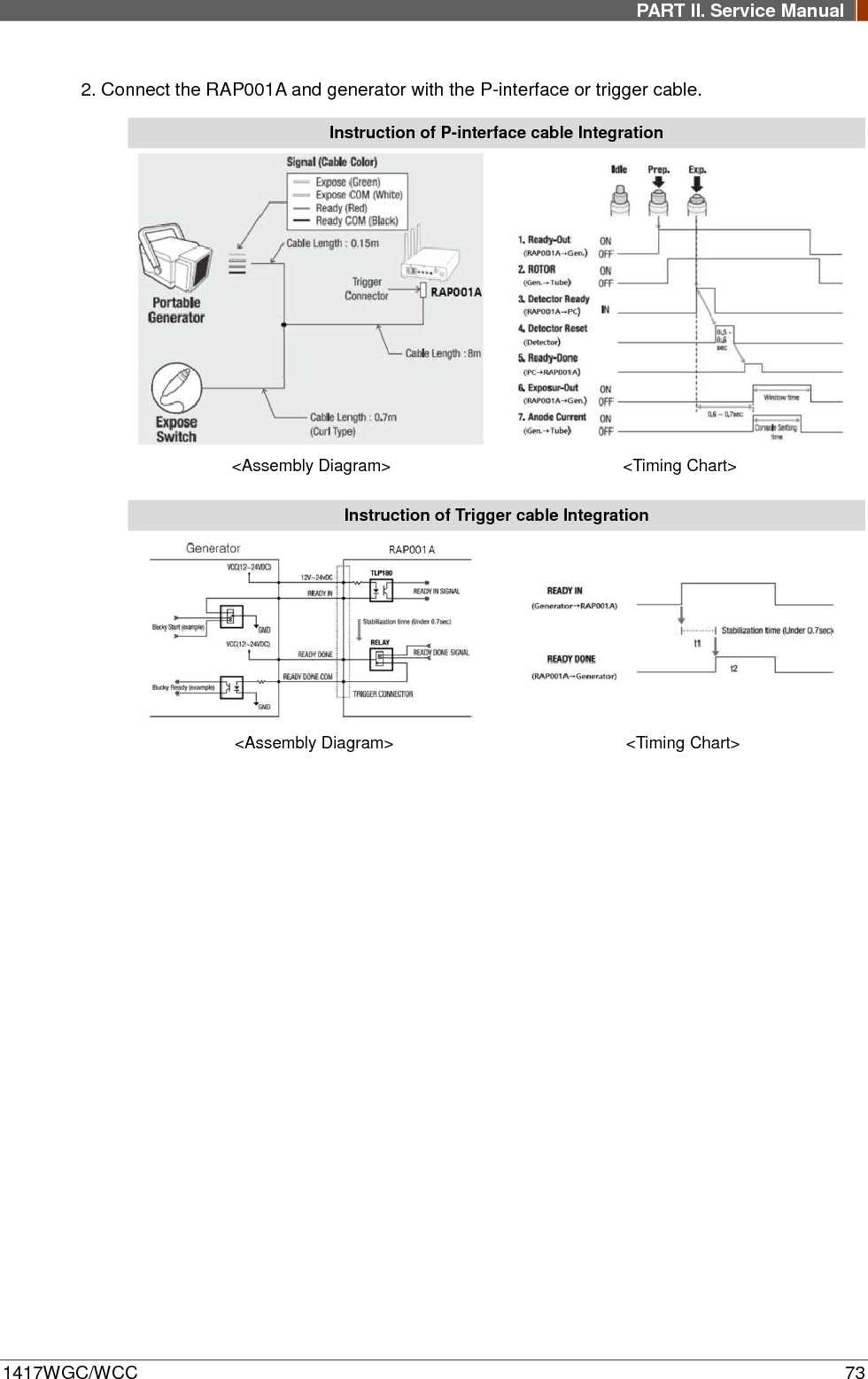
![PART II. Service Manual 1417WGC/WCC 34 2.4.5 Interface box (Optional) [Model name: RAP001A] Parameter Spec. Unit Dimension 240 X 191.2 X 65.8 (not incl. antenna) mm Weight 1.85 Kg Input rate 85 ~ 264VAC (50/60Hz) - Output Typ. 24VDC (Max 5.4A) Wireless communication 802.11 a/g/n Wireless LAN, up to 867Mbps - Wired communication Ethernet 1Gbps Detector Port 3 Trigger Port 1 2.4.6 Power Supply (Optional) [Model name -RP003A] Parameter Spec. Unit Dimension 188 X 92 X 41.5 mm Weight 0.5 Kg Rated power supply(Input) 100-240VAC (50/60Hz) - Rated power supply(Output) Typ. 24VDC (Max 1.6A) - 2.4.7 AGI Box (Optional) Parameter Spec. Unit Dimension 92.5 X 119 X 33.5 mm Weight 0.3 Kg 2.4.8 IrDA module (Optional) [Model name – RI001A] Parameter Spec. Unit Dimension 66 X 46 X 9.5 mm Weight 0.1 Kg 2.4.9 Battery Charger (Optional) [Model name: RC120WA] Parameter Spec. Unit Size 200 x 100 x 150 mm Weight 0.9 Kg Input 20 VDC Output 12.6 VDC 2.4.10 Battery Charger Adapter (Optional) [Model name: PMP120-13-3] Parameter Spec. Unit Size 160 x 76 x 43.7 mm](https://usermanual.wiki/Rayence/RY1417WHD/User-Guide-3524108-Page-34.png)
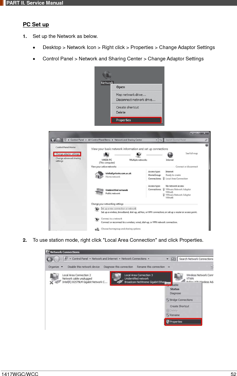
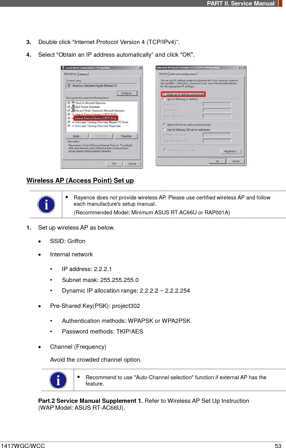
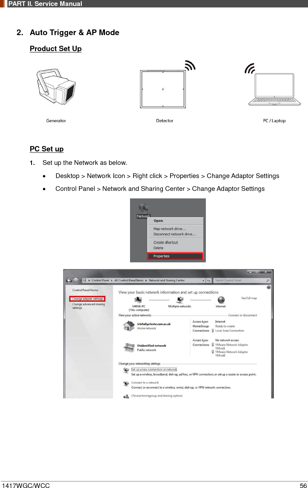
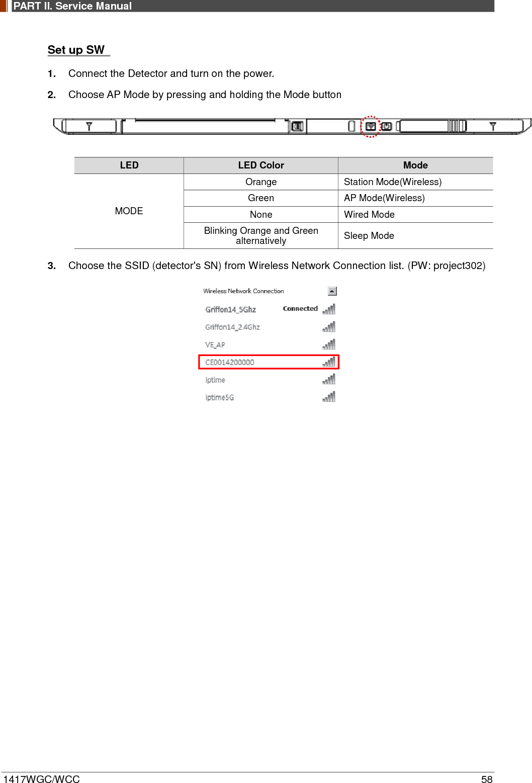
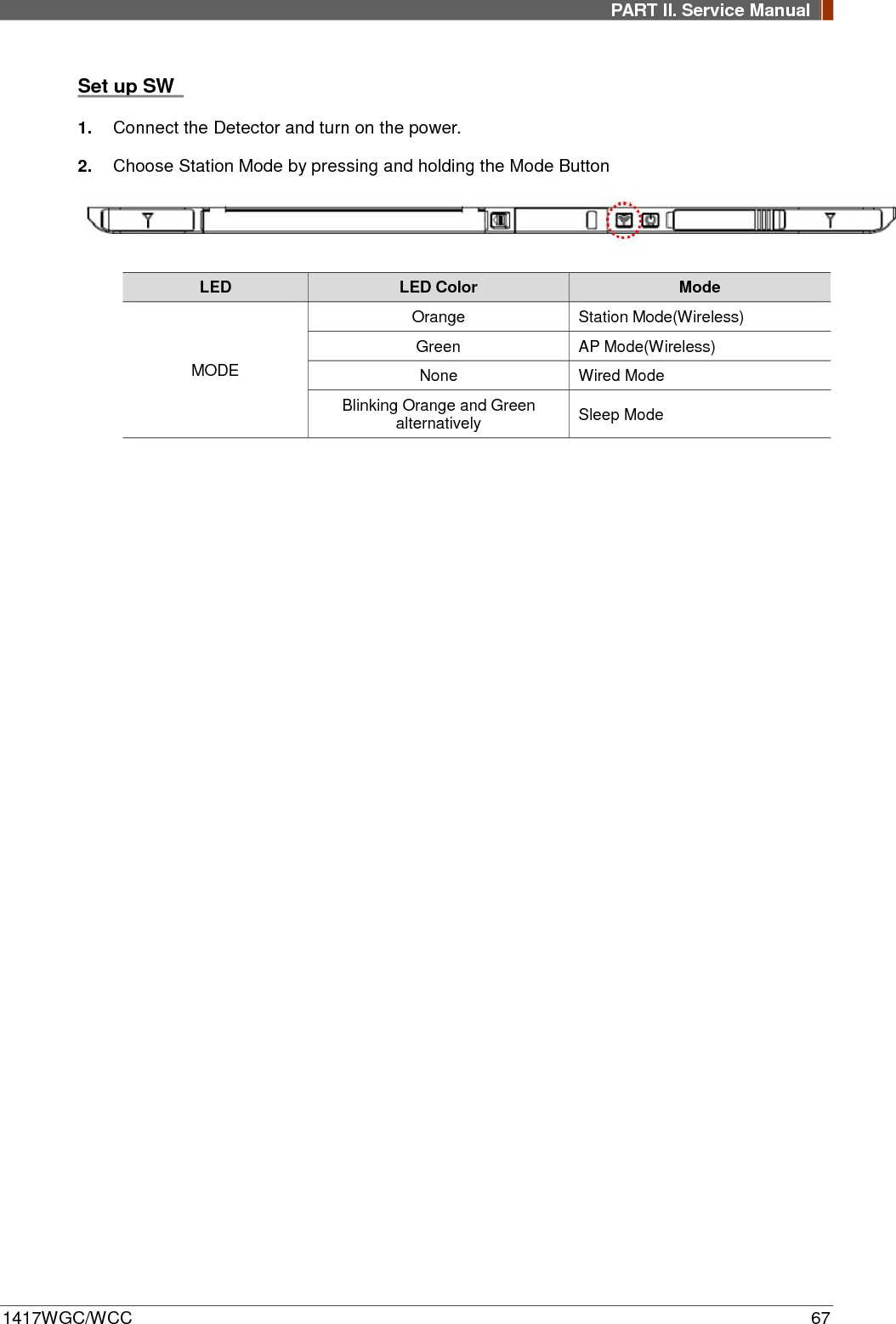
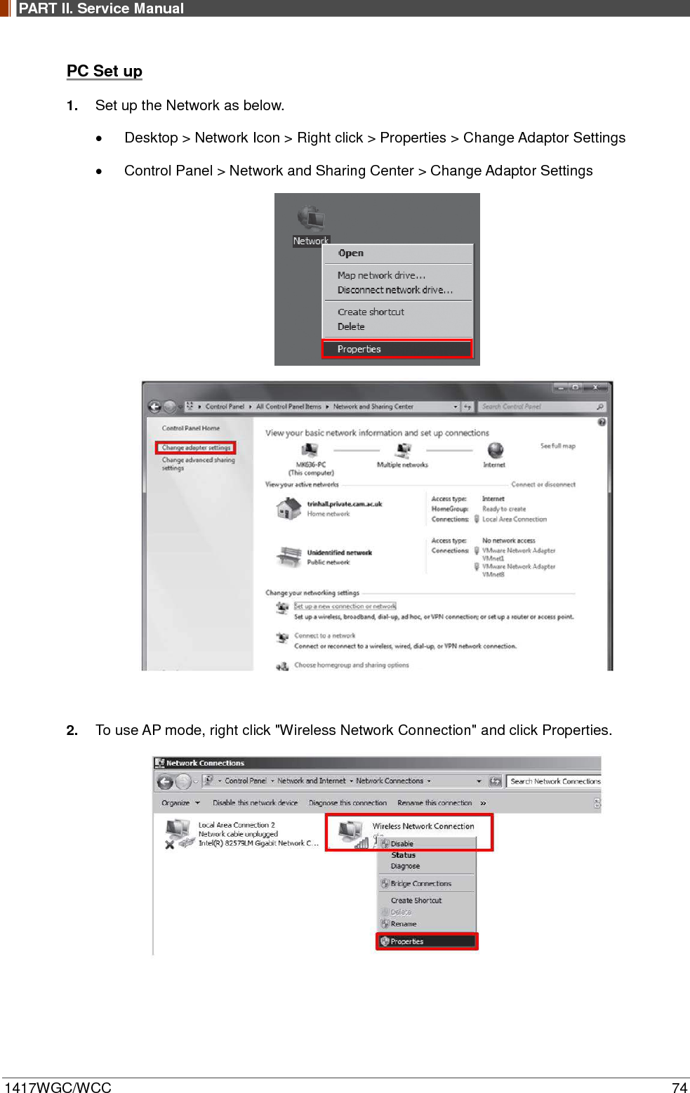
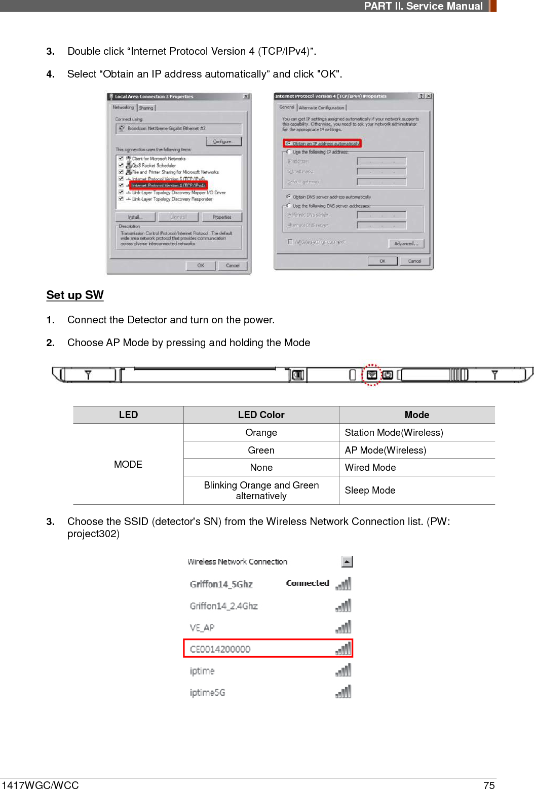
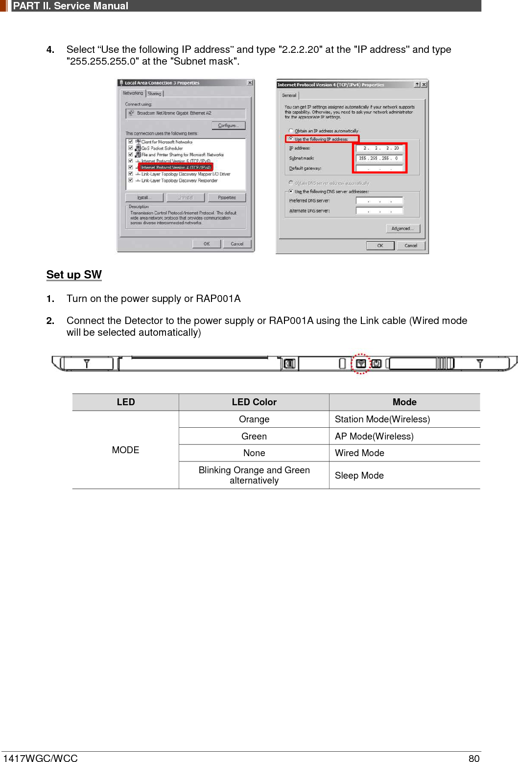
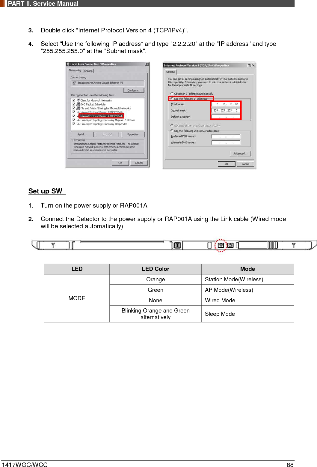
![PART II. Service Manual 1417WGC/WCC 54 Set up SW 1. Connect Detector and turn on the power. 2. Choose Station Mode by pressing and holding the Mode Button. LED LED Color Mode MODE Orange Station Mode(Wireless) Green AP Mode(Wireless) None Wired Mode Blinking Orange and Green alternatively Sleep Mode 3. Open “_vadav.lnk” from “C:\davinci”. Once the program is opened and the detector is connected, the LINK LED light from the detector will blink and the Detector Status will display information of the detector as below. Once the correct Sensor IP is put into the Davinci, it will automatically pull the parameter of the connected detector. Model type Parameter Selected 1417WCC _127A [69]1417WCC_127A.par 1417WCC _140A [71]1417WCC_140A.par 1417WGC _127A [70]1417WGC_127A.par 1417WGC _140A [72]1417WGC_140A.par Default IP address for wireless connection is 2.2.2.100 and for wired connection is 2.2.2.101. If the IP address needs to be changed, please refer to 2.1 Detector IP Address Set Up in Part.2 Service Manual.](https://usermanual.wiki/Rayence/RY1417WHD/User-Guide-3524108-Page-54.png)
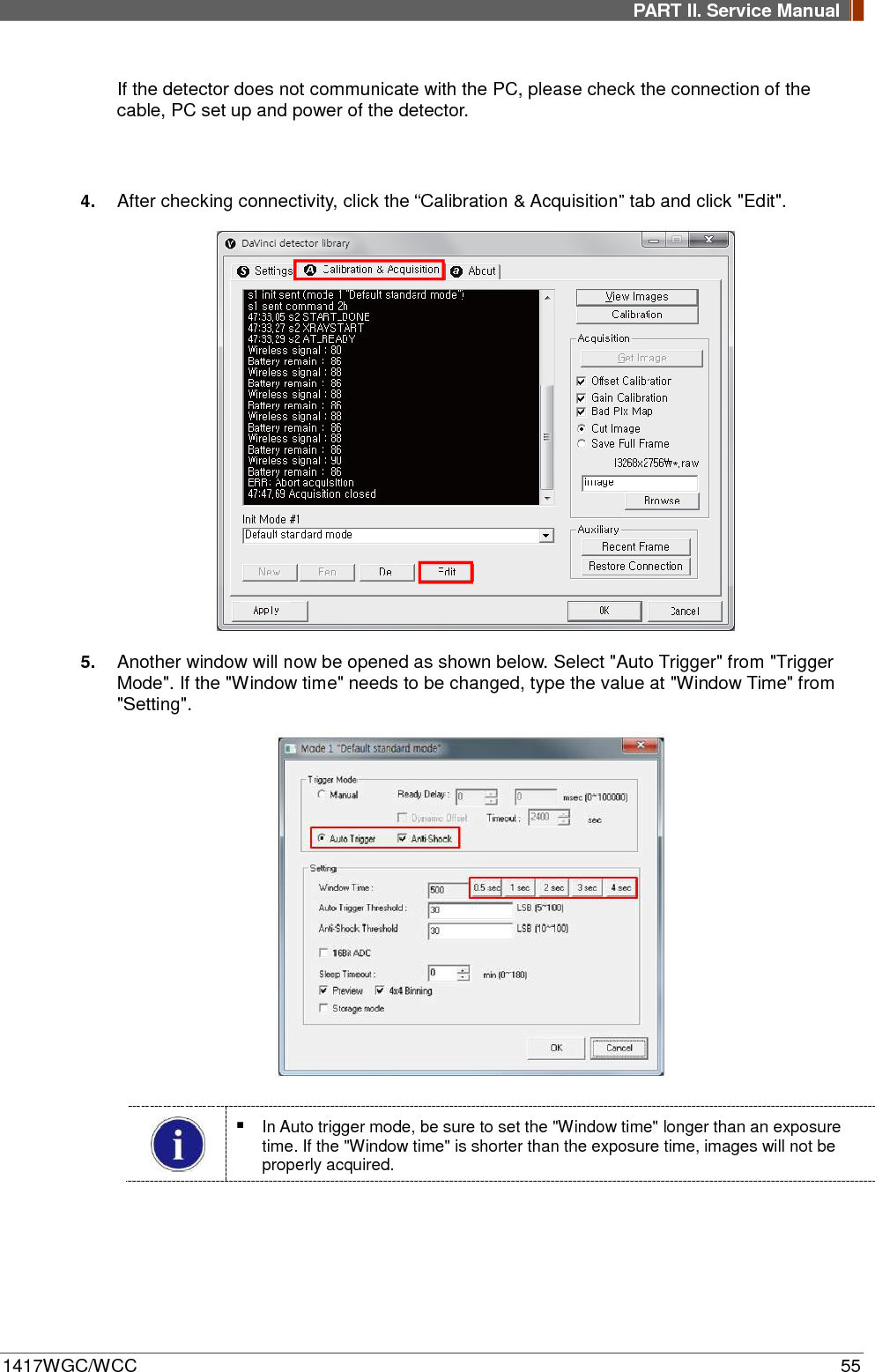
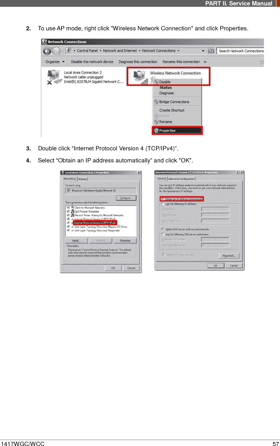
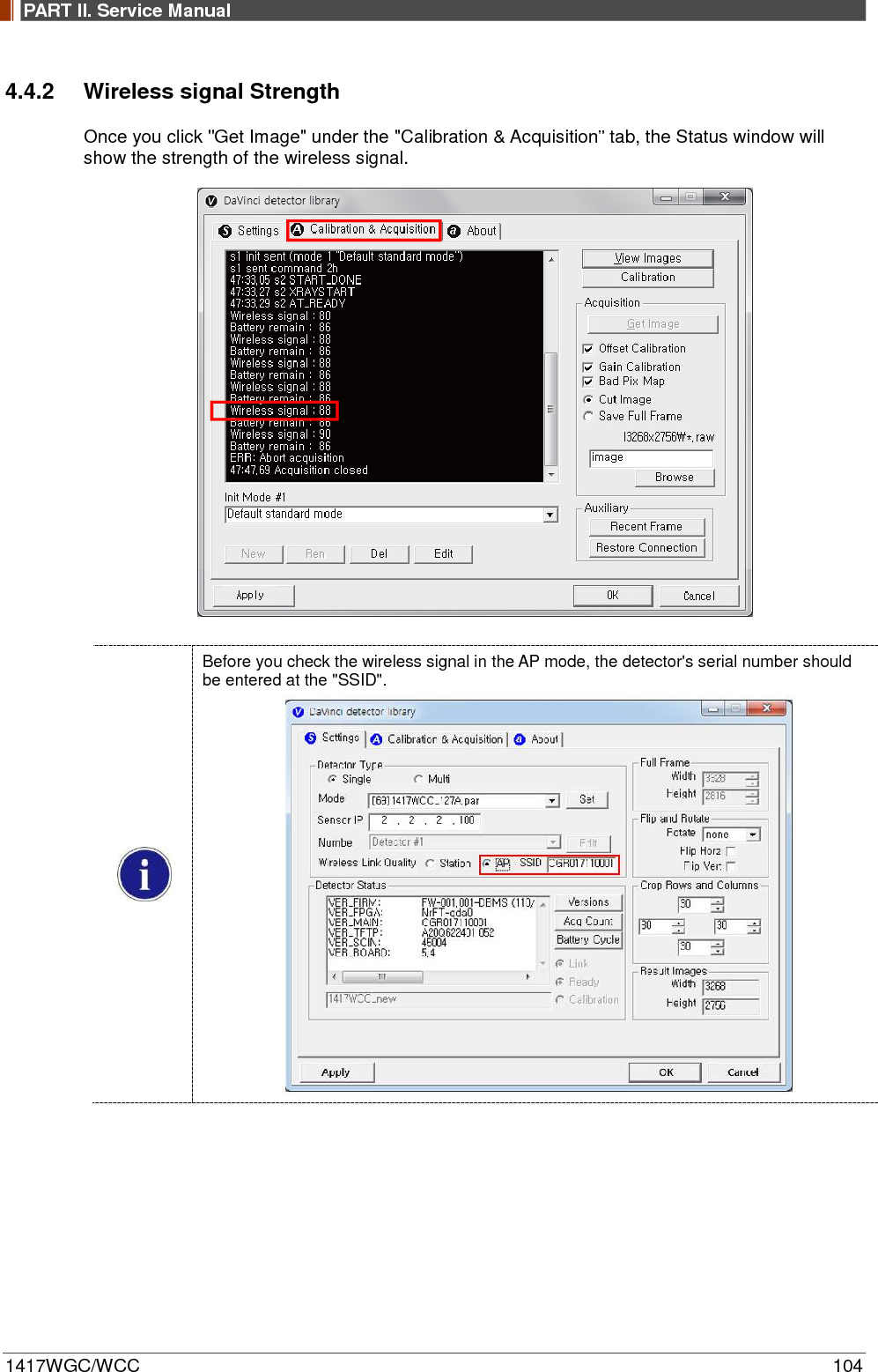
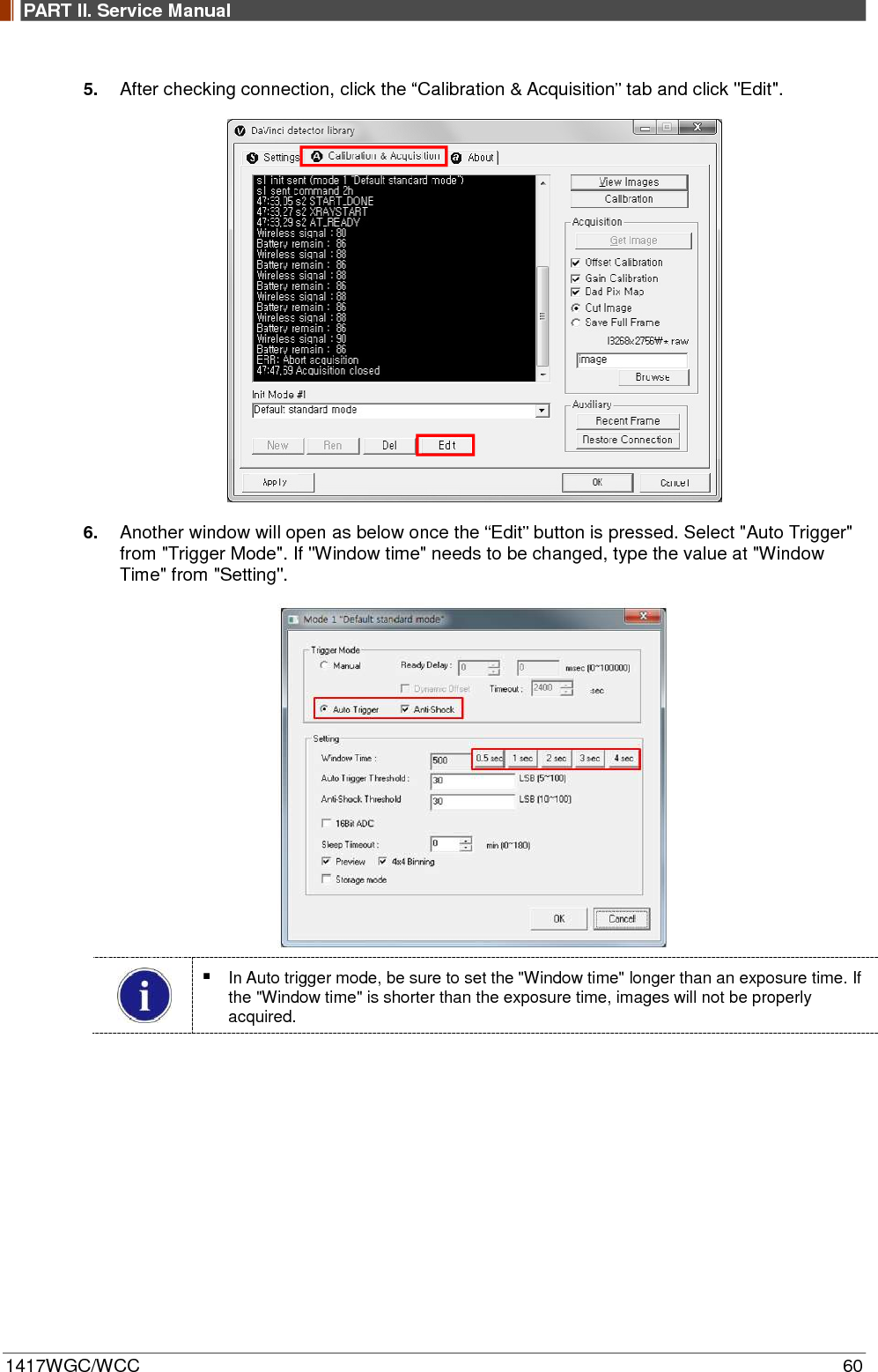
![PART II. Service Manual 1417WGC/WCC 59 4. Open “_vadav.lnk” from “C:\davinci”. Once the program is opened and the detector is connected, the LINK LED light will blink and the Detector Status will display detector information as below. Once the correct Sensor IP is put into the Davinci, it will automatically pull the parameter of the connected detector. Model type Parameter Selected 1417WCC _127A [69]1417WCC_127A.par 1417WCC _140A [71]1417WCC_140A.par 1417WGC _127A [70]1417WGC_127A.par 1417WGC _140A [72]1417WGC_140A.par Default IP address for wireless connection is 2.2.2.100 and for wired connection is 2.2.2.101. If the IP address needs to be changed, please refer to 2.1 Detector IP Address Set Up in Part.2 Service Manual. In the AP mode, select "AP" from "Wireless Link Quality" and type the detector's serial number at the "SSID". If the detector does not communicate with the PC, please check the connection of the cable, PC set up and power of the detector.](https://usermanual.wiki/Rayence/RY1417WHD/User-Guide-3524108-Page-59.png)


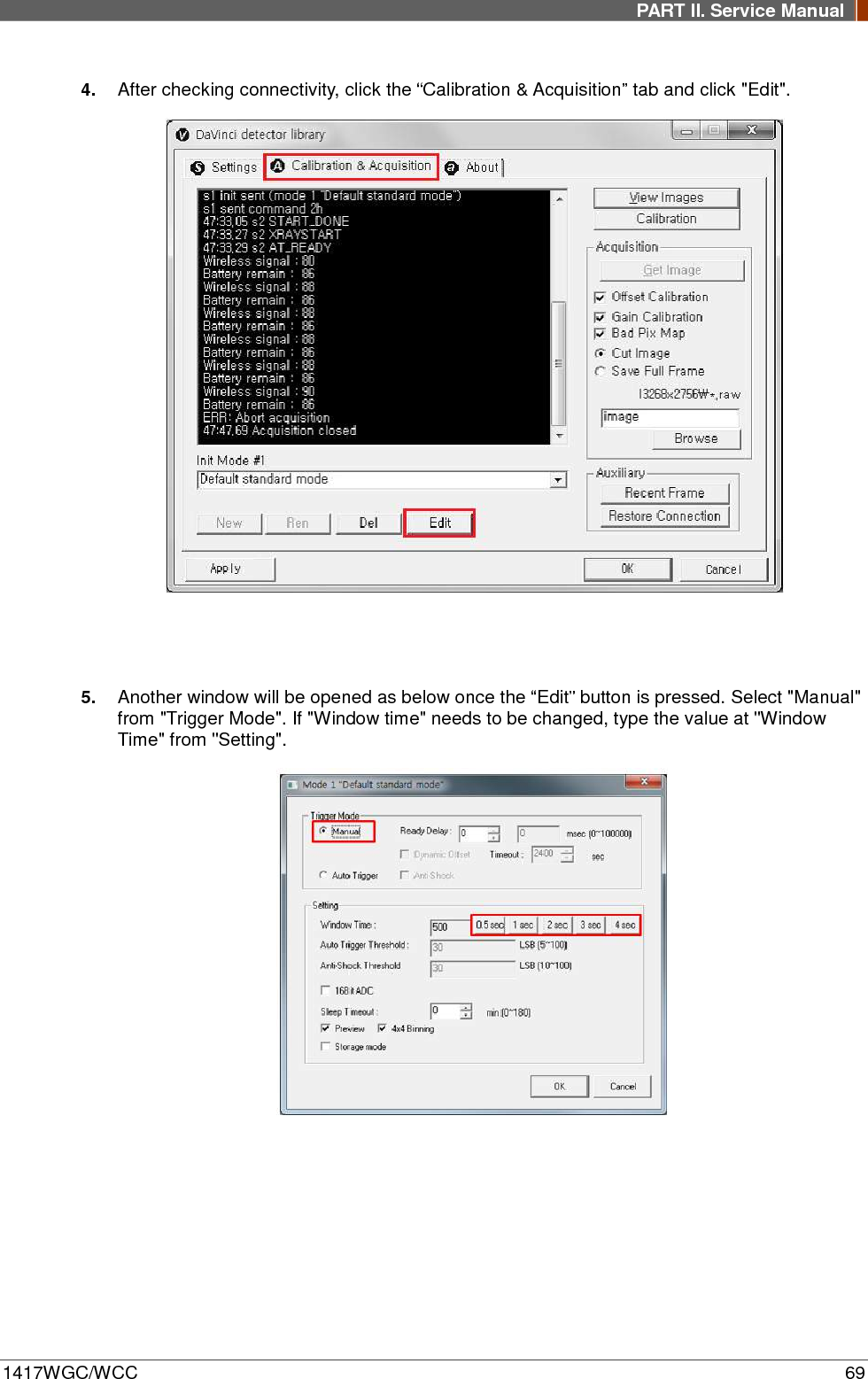
![PART II. Service Manual 1417WGC/WCC 68 3. Open “_vadav.lnk” from “C:\davinci”. Once the program is opened and the detector is connected, the LINK LED light will blink and the Detector Status will display detector information as below. Once the correct Sensor IP is put into the Davinci, it will automatically pull the parameter of the connected detector. Model type Parameter Selected 1417WCC _127A [69]1417WCC_127A.par 1417WCC _140A [71]1417WCC_140A.par 1417WGC _127A [70]1417WGC_127A.par 1417WGC _140A [72]1417WGC_140A.par Default IP address for wireless connection is 2.2.2.100 and for wired connection is 2.2.2.101. If the IP address needs to be changed, please refer to 2.1 Detector IP Address Set Up in Part.2 Service Manual. If the detector does not communicate with the PC, please check the connection of the cable, PC set up and power of the detector.](https://usermanual.wiki/Rayence/RY1417WHD/User-Guide-3524108-Page-68.png)
![PART II. Service Manual 1417WGC/WCC 76 4. Open “_vadav.lnk” from “C:\davinci”. Once the program is opened and the detector is connected, the LINK LED light from the detector will blink and the Detector Status will display panel information as below. Once the correct Sensor IP is put into the Davinci, it will automatically pull the parameter of the connected detector. Model type Parameter Selected 1417WCC _127A [69]1417WCC_127A.par 1417WCC _140A [71]1417WCC_140A.par 1417WGC _127A [70]1417WGC_127A.par 1417WGC _140A [72]1417WGC_140A.par Default IP address for wireless connection is 2.2.2.100 and for wired connection is 2.2.2.101. If the IP address needs to be changed, please refer to 2.1 Detector IP Address Set Up in Part.2 Service Manual. In the AP mode, select "AP" from "Wireless Link Quality" and type the detector's serial number at the "SSID". If the detector does not communicate with PC, please check the connection of the cable, PC set up and power of detector.](https://usermanual.wiki/Rayence/RY1417WHD/User-Guide-3524108-Page-76.png)
![PART II. Service Manual 1417WGC/WCC 81 3. Open “_vadav.lnk” from “C:\davinci”. Once the program is opened and the detector is connected, the LINK LED light will blink and the Detector Status will display detector information as below. Once the correct Sensor IP is put into the Davinci, it will automatically pull the parameter of the connected detector. Model type Parameter Selected 1417WCC _127A [69]1417WCC_127A.par 1417WCC _140A [71]1417WCC_140A.par 1417WGC _127A [70]1417WGC_127A.par 1417WGC _140A [72]1417WGC_140A.par Default IP address for wireless connection is 2.2.2.100 and for wired connection is 2.2.2.101. If the IP address needs to be changed, please refer to 2.1 Detector IP Address Set Up in Part.2 Service Manual. If the detector does not communicate with the PC, please check the connection of the cable, PC set up and power of the detector.](https://usermanual.wiki/Rayence/RY1417WHD/User-Guide-3524108-Page-81.png)

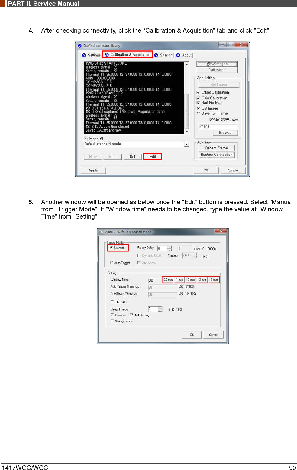
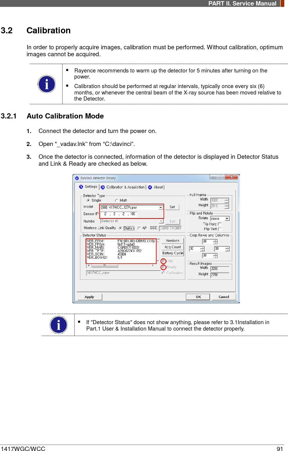
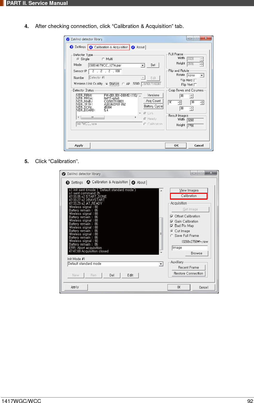
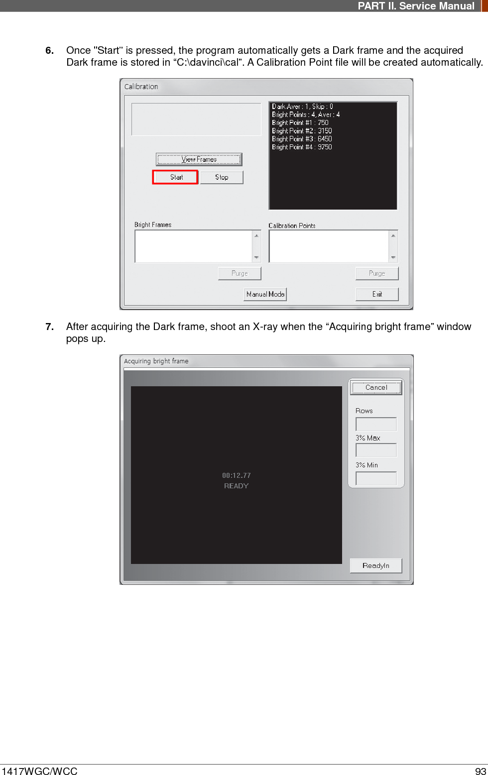
![PART II. Service Manual 1417WGC/WCC 89 3. Open “_vadav.lnk” from “C:\davinci”. Once the program is opened and the detector is connected, the LINK LED light will blink and the Detector Status will display detector information as below. Once the correct Sensor IP is put into the Davinci, it will automatically pull the parameter of the connected detector. Model type Parameter Selected 1417WCC _127A [69]1417WCC_127A.par 1417WCC _140A [71]1417WCC_140A.par 1417WGC _127A [70]1417WGC_127A.par 1417WGC _140A [72]1417WGC_140A.par Default IP address for wireless connection is 2.2.2.100 and for wired connection is 2.2.2.101. If the IP address needs to be changed, please refer to 2.1 Detector IP Address Set Up in Part.2 Service Manual. If the detector does not communicate with the PC, please check the connection of the cable, PC set up and power of the detector.](https://usermanual.wiki/Rayence/RY1417WHD/User-Guide-3524108-Page-89.png)