Rayence RY1417WHD Medical Image Processing Unit User Manual 1417WCC WGC
Rayence Co., Ltd. Medical Image Processing Unit 1417WCC WGC
Rayence >
User Manual

1417WGC/WCC
User & Installation Manual
R-USM-020/021
Date: 2017-04-19
Preface
1417WGC/WCC 3
Preface
Please note that this information is for proper use and safety of the equipment. The following
symbols may indicate a hazardous situation in which, if not heeded, may result in serious injury
or even death to the user or others, or damage to the equipment.
Used to emphasize essential information.
Be sure to read this information to avoid incorrect operation.
WARNING
Indicates warning and safety instructions. If not adhered to, it could result in death or
serious injury to the user or others.
CAUTION
Indicates a hazardous situation which, if not heeded, may result in minor or moderate
injury to the user or others, or damage to the equipment.
For users in the United States:
United State federal law restricts this equipment to be used by or on the order of a
physician.
Since the X-ray exposure condition can be changed depending on the age, gender and
bone density of the patient, in case of Pediatric, X-ray exposure condition can be changed
by expert’s judge. For further information, please refer to FDA Pediatric X-ray Imaging
webpage.
http://www.fda.gov/radiation-
emittingproducts/radiationemittingproductsandprocedures/medicalimaging/ucm298899.htm
For users in other countries:
This equipment is to be used by or on the order of a licensed person under the related laws
for each country.
Intended use:
Digital Flat Panel X-Ray Detector is indicated for digital imaging solution designed for general
radiographic system for human anatomy. It is intended to replace film or screen based
radiographic systems in all general purpose diagnostic procedures. Not to be used for
mammography.
VATECH Dental Manufacturing Ltd.
Chancery House, St. Nicholas Way, Sutton, SM1 1JB, United Kingdom
Tel : +44 208 652 1990, Fax : +44 208 652 1909
Rayence Co., Ltd.
14, Samsung 1-ro 1-gil, Hwaseong-si, Gyeonggi-do, Korea
www.rayence.com

Contents
4 1417WGC/WCC
Contents
PART I. User & Installation Manual 5
1. Safety Information ......................................................................................... 6
1.1 Safety Standard .................................................................................... 6
1.2 Symbols .............................................................................................. 12
1.3 Warning .............................................................................................. 14
1.4 Caution ............................................................................................... 16
1.5 Safety Information ............................................................................... 20
1.6 Label and Location of Attachment ......................................................... 22
1.7 Summary of usability specifications ....................................................... 22
2. Product Introduction and Specification ........................................................... 23
2.1 Product Features .................................................................................. 23
2.2 Product Components ............................................................................ 24
2.3 Part Names and Functions .................................................................... 24
2.4 Part Specifications ................................................................................ 32
2.5 Environmental Requirements ................................................................ 36
2.6 Dimensions (Unit: mm) ........................................................................ 37
3. Installation and Calibration ............................................................................ 42
3.1 Installation .......................................................................................... 42
3.2 Calibration ........................................................................................... 91
4. Usage ........................................................................................................... 97
4.1 Set Up ................................................................................................. 97
4.2 Image Acquisition ................................................................................ 99
4.3 View Images ...................................................................................... 101
4.4 Additional Function ............................................................................. 103
5. Maintenance ............................................................................................... 114
5.1 Cleaning ............................................................................................ 114
5.2 Inspection ......................................................................................... 114
5.3 Replaceable Parts and Instruction of Replacement ............................... 115
5.4 Disposal or Recycling .......................................................................... 116
6. Warranty .................................................................................................... 117
6.1 Warranty ........................................................................................... 117

PART II. Service Manual
1417WGC/WCC 5
PART I. User & Installation Manual
1. Safety Information………….…………………….8
2. Product Introduction and Specification……25
3. Installation and Calibration…………………..44
4. Usage……………………………...………………..99
5. Maintenance………………………...…………..116
6. Warranty………………………..…………..……119

PART II. Service Manual
1417WGC/WCC 6
1. Safety Information
1.1 Safety Standard
1.1.1 Medical Device Classification
Item Description
Classification by protection type against Electric
Shock Class I or Internally Powered Equipment
Classification according to the degree of
protection against ingress of water IP53
Mode of operation Continuous Operation
Environment of Use This equipment is not suitable for use in the
presence of flammable anesthetic or oxygen.
1.1.2 Regulations
1. Safety and Electromagnetic Compatibility Information
Item Description
IEC/EN/UL 60601-1 Medical electrical equipment
Part 1: General requirements for safety
IEC/EN 60601-1-2 Medical electrical equipment
Part 2: Electromagnetic compatibility-requirements and tests
This equipment has been tested and found to comply with the limits for medical devices in IEC
60601-1-2. These limits are designed to provide reasonable protection against harmful
interference in a typical medical installation.
This equipment generates, uses and can radiate radio frequency energy. If not installed and
used in accordance with the instructions, it may cause harmful interference to other devices in
the vicinity. However, there is no guarantee that interference will not occur in a particular
installation. If this equipment does cause harmful interference to other devices, which can be
determined by turning the equipment off and on, the user is encouraged to try to correct the
interference by one or more of the following measures.
Reorient or relocate the equipment.
Increase the separation between the equipment.
Connect the equipment into an outlet on a circuit different from that to which the other
devices are connected.
Contact Rayence Customer Service team or authorized agent for help.

PART II. Service Manual
1417WGC/WCC 7
2. Radio Frequency compliance
FCC (For USA)
• FCC ID: QIIRY1417WHD
• 5.15- 5.25 GHz band is restricted to indoor operations only.
• Host device of the approved module shall be marked with the following item:
• Compliance with FCC requirement 15.407(c)
Data transmission is always initiated by software, which is the passed down through the
MAC, through the digital and analog baseband, and finally to the RF chip. Several special
packets are initiated by the MAC. These are the only ways the digital baseband portion will
turn on the RF transmitter, which it then turns off at the end of the packet. Therefore, the
transmitter will be on only while one of the aforementioned packets is being transmitted. In
other words, this device automatically discontinues transmission in case of either absence
of information to transmit or operational failure.
This device complies with part 15 of the FCC Rules. Operation is subject to the following
two conditions: (1) This device may not cause harmful interference, and (2) this device
must accept any interference received, including interference that may cause undesired
operation.
FCC CAUTION
Changes or modifications not expressly approved by the party responsible for compliance
could void the user’s authority to operate the equipment. This transmitter must not be co-
located or operated in conjunction with any other antenna or transmitter.
When installing it in a mobile equipment
This equipment complies with FCC radiation exposure limits set forth for an uncontrolled
environment and meets the FCC radio frequency (RF) Exposure Guidelines in CFR
§2.1093.
When you use the detector with wire mode, the wireless function is automatically off.
• 5150-5250 MHz band is restricted to indoor operations only.
< Note >
The front with touch configuration was only tested since only the front is touched to human
body in normal operation of this device
The highest reported SAR values for head & body are: 1.18 W/kg & 1.06 W/kg respectively.

PART II. Service Manual
1417WGC/WCC 8
IC Notice (For CANADA)
IC: 10742A-1417WHD
This Class A digital apparatus complies with Canadian ICES-003
This device complies with Industry Canada licence-exempt RSS standard(s). Operation is
subject to the following two conditions: (1) this device may not cause interference, and (2)
this device must accept any interference, including interference that may cause undesired
operation of the device.
Le present appareil est conforme aux CNR d'Industrie Canada applicables aux appareils
radio exempts de licence. L'exploitation est autorisee aux deux conditions suivantes: (1)
l'appareil ne doit pas produire de brouillage, et (2) l'utilisateur de l'appareil doit accepter
tout brouillage radioelectrique subi, meme si le brouillage est susceptible d'en
compromettre le fonctionnement.
R&TTE Notice (European Union)
The product compliance to the Directive 1999/5/EC as radio equipment and telecommunications
terminal equipment.
Authorized by Notified Body (code no. : 0678)
5150-5250 MHz band is restricted to indoor operations only.
Japan Ratio Raw (For Japan)
Type Certification No. : 011-170018
3. Electro-Magnetic Compatibility Information
Electro-Magnetic Emissions
This 1417WCC/WGC is intended for use in the electromagnetic environment specified below.
The customer or the user of the 1417WCC/WGC should assure that it is used in such an
environment.
Immunity Test Compliance Electromagnetic Environment – Guidance
RF Emissions CISPR 11 Group 1
The 1417WCC/WGC uses RF energy only for its
internal function. Therefore, its RF emissions are very
low and are not likely to cause any interference in
nearby electronic equipment.
RF Emissions CISPR 11 Class A The 1417WCC/WGC is suitable for use in all
establishments, including domestic establishments
and those directly connected to the public low-voltage
power supply network that supplies buildings used for
domestic purposes. provided the following warning is
heeded:
Warning: This equitpment/system is intended for use
by healthcare professionals only, This
equipment/system may cause radio interference or
may disrupt the operation of nearby equipment. It
may be necessary to take mitigation measures, such
as re-orenting or relocating the 1717WCC/WGC or
shielding the location.
Harmonic emissions
IEC 61000-3-2 Class A
Voltage fluctuations / Flicker
emissions IEC 61000-3-3 Complies

PART II. Service Manual
1417WGC/WCC 9
Electro-Magnetic Immunity
This 1417WCC/WGC is intended for use in the electromagnetic environment specified below.
The customer or the user of the 1417WCC/WGC should assure that it is used in such an
environment.
Immunity Test IEC 60601-1-2 Test Level Compliance Level Electromagnetic environment
– guidance
Electrostatic
discharge (ESD)
IEC 61000-4-2
± 6 kV contact
± 8 kV air
IEC 60601-1-2 Test
level
Floors should be wood,
concrete or ceramic tiles. If
floors are covered with synthetic
material, relative humidity
should be at least 30%.
Electrical fast
transient/burst
IEC 61000-4-4
± 2 kV for power supply
lines
± 1 kV for input/output lines
IEC 60601-1-2 Test
level
Mains power quality should be
that of a typical commercial or
hospital environment.
Surge
IEC 61000-4-5
± 1 kV line(s) to lines(s)
± 2 kV line(s) to earth
IEC 60601-1-2 Test
level
Mains power quality should be
that of a typical commercial or
hospital environment.
Voltage dips,
short
interruption, and
voltage
variations on
power supply
input lines
IEC 60601-4-11
<5% Uт
for 0.5cycle
40% Uт
for 5, 6 cycles
70% Uт
for 25, 30 cycles
<5% Uт
for 5s
IEC 60601-1-2 Test
level
Mains power quality should be
that of a typical commercial or
hospital environment. If the user
of the 1417WCC/WGC requires
continued operation during
power mains interruptions, it is
recommended that the
1417WCC/WGC be powered
from an uninterruptible power
source or battery.
Power
frequency
(50/60 Hz)
IEC 61000-4-8
3.0 A/m IEC 60601-1-2 Test
level
Power frequency magnetic
fields should be at levels
characteristic of a typical
location in a typical commercial
or hospital environment.
NOTE UT is the a.c mains voltage prior to application of the test level.
PART II. Service Manual
1417WGC/WCC 10
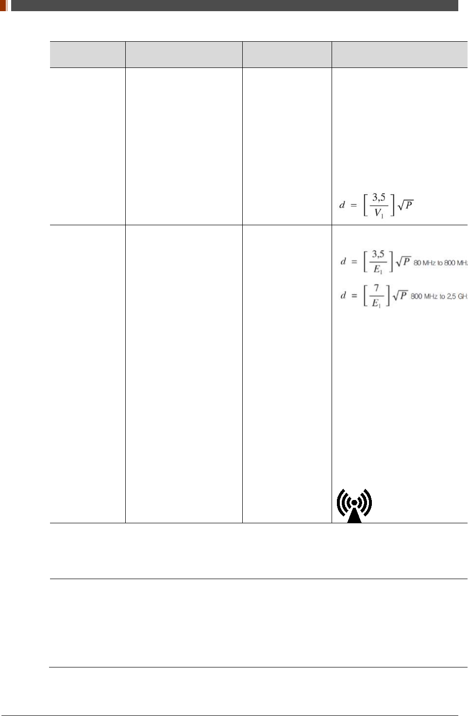
Immunity Test IEC 60601-1-2 Test Level Compliance Level Electromagnetic environment
– guidance
Conducted RF
IEC61000-4-6 3 Vrms
150 kHz to 80MHz 3 Vrms
Portable and mobile RF
communications equipment
should be used no closer to any
part of the 1417WCC/WGC,
including cables, than the
recommended separation
distance calculated from the
equation applicable to the
frequency of the transmitter.
Recommended separation
distance
Radiated RF
IEC61000-4-3 3 V/m
80 MHz to 2.5GHz 3 V/m
Recommended separation
distance
Where P is the maximum output
power rating of the transmitter in
watts (W) according to the
transmitter manufacturer and d
is the recommended separation
distance in meters (m).
Field strengths from fixed RF
transmitters, as deter-mined by
an electromagnetic site survey,
(a) Should be less than the
compliance level in each
frequency range (b).
Interference may occur in the
vicinity of equipment marked
with the
following symbol:
Note 1) Uт is the A.C. mains voltage prior to application of the test level.
Note 2) At 80 MHz and 800 MHz, the higher frequency range applies.
Note 3) These guidelines may not apply in all situations. Electromagnetic propagation is affected by
absorption and reflection from structures, objects and people.
(a) Field strengths from fixed transmitters, such as base stations for radio (cellular/cordless) telephones
and land mobile radios, amateur radio, AM and FM radio broadcast and TV broadcast cannot be predicted
theoretically with accuracy. To assess the electromagnetic environment due to fixed RF transmitters, an
electromagnetic site survey should be considered. If the measured field strength the location in which the
1417WCC/WGC is used exceeds the applicable RF compliance level above, the 1417WCC/WGC should
be observed to verify normal operation. If abnormal performance is observed, additional measures may be
necessary, such as re-orienting or relocating the 1417WCC/WGC.
(b) Over the frequency range 150 kHz to 80 MHz, field strengths should be less than 3 V / m.

PART II. Service Manual
1417WGC/WCC 11
Recommended separation distance between portable and mobile RF
communications equipment and the 1417WCC/WGC
The 1417WCC/WGC is intended for use in an electromagnetic environment in which radiated
RF disturbances are controlled. The user of the 1417WCC/WGC can help prevent
electromagnetic interference by maintaining a minimum distance between portable and mobile
RF communications equipment (transmitters) and the 1417WCC/WGC as recommended below,
according to the maximum output power of the communications equipment.
Rated maximum
output power (W)
of transmitter
Separation distance (m) according to frequency of transmitter
150kHz to 80MHz
80MHz to 800MHz 800MHz to 2.5GHz
0.01 0.12 0.12 0.23
0.1 0.38 0.38 0.73
1 1.2 1.2 2.3
10 3.8 3.8 7.3
100 12 12 23
For transmitters rated at a maximum output power not listed above, the recommended separation
distance (d) in meters (m) can be estimated using the equation applicable to the frequency of the
transmitter, where P is the maximum output power rating of the transmitter in watts (W) according to
the transmitter manufacturer.
Note 1) At 80 MHz and 800 MHz, the separation distance for the higher frequency range applies.
Note 2) These guidelines may not apply in all situations. Electromagnetic propagation is affected by
absorption and reflection from structures, objects, and people.
PART II. Service Manual
1417WGC/WCC 12
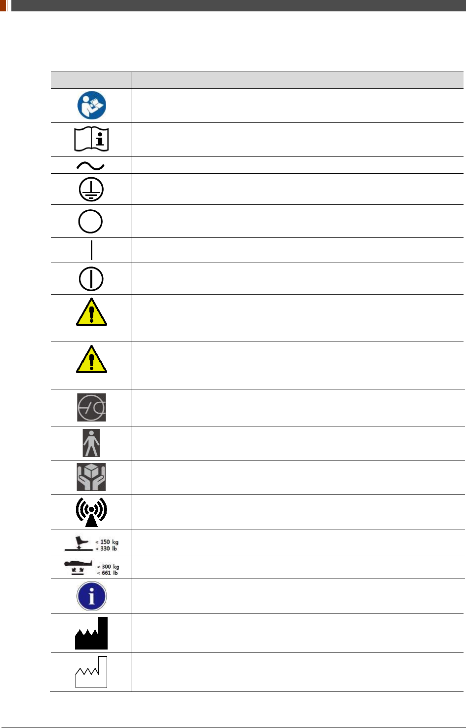
1.2 Symbols
Symbols Descriptions
Refer to instruction manual / booklet
Consult instructions for use
Alternate current
Protective earth (Ground)
Off (power : disconnect from the main switch)
On (power : connect from the main switch)
On / Off (button type)
WARNING
Warning
CAUTION
Caution
To indicate a reference to the X-ray tube, for example to identify the surface of a
component such as a focused ant scatter grid, that has to be oriented towards the
X-ray tube.
This is a Type B applied part according to UL 60601-1 and IEC 60601-1.
Handle with care
Non-ionizing radiation
Partial Pressure Limit
Overall Pressure
Read carefully
Manufacturer
Date of manufacture
PART II. Service Manual
1417WGC/WCC 13
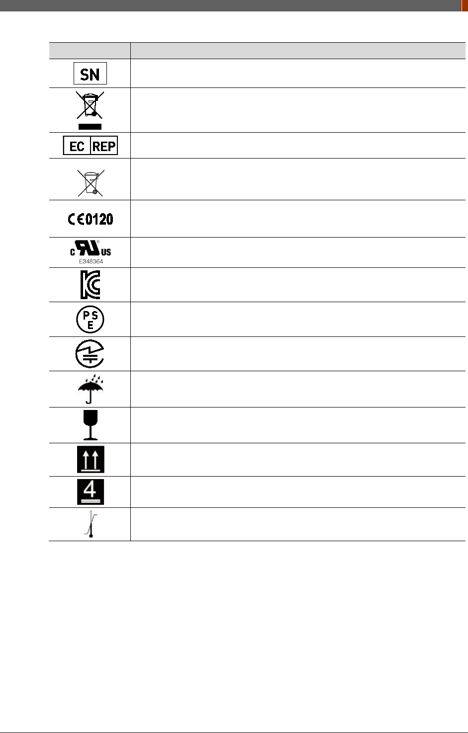
Symbols Descriptions
Serial number
WEEE : Waste Electrical and Electronic Equipment
Authorized representative in the European community.
Batteries Marking (Battery Directive 2006/66/EC)
CE symbol grants the equipment compliance to the European Directive for
Medical Devices 93/42/EEC as a class �a device and 1999/5/EC. Authorized by
Notified Body SGS (code no.:0120) of British
Recognized Component Mark for Canada and the United States
For Korea
Symbol for safety
For Japan
Product Safety of Electrical Appliance & Materials
For JAPAN
Japan Radio Law Certification
Keep dry
Fragile, handle with care
This side up
4 layer stacking
Temperature limit
PART II. Service Manual
1417WGC/WCC 14
1.3 Warning
WARNING
Environment of Use and Storage
Follow the specified process of operational instructions written in this manual for the
safety of the users and patients.
Does not use or store the detector near any flammable chemicals such as thinner,
benzene, etc. Also, this detector is not a category AP or APG equipment. If chemicals
are spilled or evaporate, it may result in fire or electric shock through contact with
electric parts inside the detector. Also, some disinfectants are flammable. Be sure to
take care when using them.
WARNING
Connection
Do not connect the detector with anything other than specified. Otherwise, it may result
in fire or electric shock.
To avoid the risk of electric shock, this detector must only be connected to supply
mains with protective earth.
Do not touch SIP/SOP and the patient simultaneously. There is a risk of electric shock
from current leakage.
Additional equipment connected to medical electrical equipment must comply with the
respective IEC or ISO standards (e.g. IEC 60950 for data processing equipment).
Furthermore all configurations shall comply with the requirements for medical electrical
systems (see IEC 60601-1-1 or clause 16 of the 3 Ed. of IEC 60601-1, respectively).
Anybody connecting additional equipment to medical electrical equipment configures a
medical system and is therefore responsible that the system complies with the
requirements for medical electrical systems. Attention is drawn to the fact that local
laws take priority over the above-mentioned requirements. If in doubt, contact Rayence
Customer Service team or authorized agent.
Equipment connected to the detector and in the patient environment must be powered
from a medically-isolated power source or must be a medically-isolated device.
Equipment powered from a non-isolated source can result in chassis leakage currents
exceeding safe levels. Chassis leakage current created by an accessory or device
connected to a non-isolated outlet may add to the chassis leakage current of the
detector.
WARNING
Handling
Always be sure to keep checking the condition of the system and the patient to ensure
they are normal during the use of the detector. If any problem is found, take
appropriate measures, such as stopping the operation of the detector, as required.
Never disassemble or modify the detector as it may result in fire or electric shock.
Also, since the detector incorporates parts that may cause electric shocks and other
hazardous parts, touching them may cause death or serious injury.
Do not hit or drop the detector. The detector may be damaged if it receives a strong
jolt, which may result in fire or electric shock if the detector is used without being
repaired.
WARNING
When Problem Occurs
Should any of the following occur, immediately turn OFF the power of each detector,
unplug the power supply cord from the AC outlet, and contact Rayence Customer Service
team or authorized agent.
When there is smoke, odd smell or abnormal sound.
When liquid has been spilled into the detector or a metal object has entered through an
opening.
When the detector has been dropped and it is damaged.
PART II. Service Manual
1417WGC/WCC 15
WARNING
Maintenance and Inspection
For safety reasons, be sure to turn off the power of the detector when the following
inspections are going to be performed. Otherwise, it may result in electric shock.
When the detector is going to be cleaned, be sure to turn off the power of each
detector, and unplug the power cable from the AC outlet.
Do not use any type of solvent, such as benzene. Otherwise, fire or electric shock may
result.
Wear waterproof gloves to protect your hands from direct contact with IPA (Isopropyl-
alcohol) or any other liquid.
Maintenance of the detector should be done by an authorized service provider. If
problem still cannot be corrected, it may result in fire or electric shock.
WARNING
Wireless Connection
SSID & PSK value should match to Router’s setting. If these values are not matched
with Detector and Router, the connection is not allowed for security.
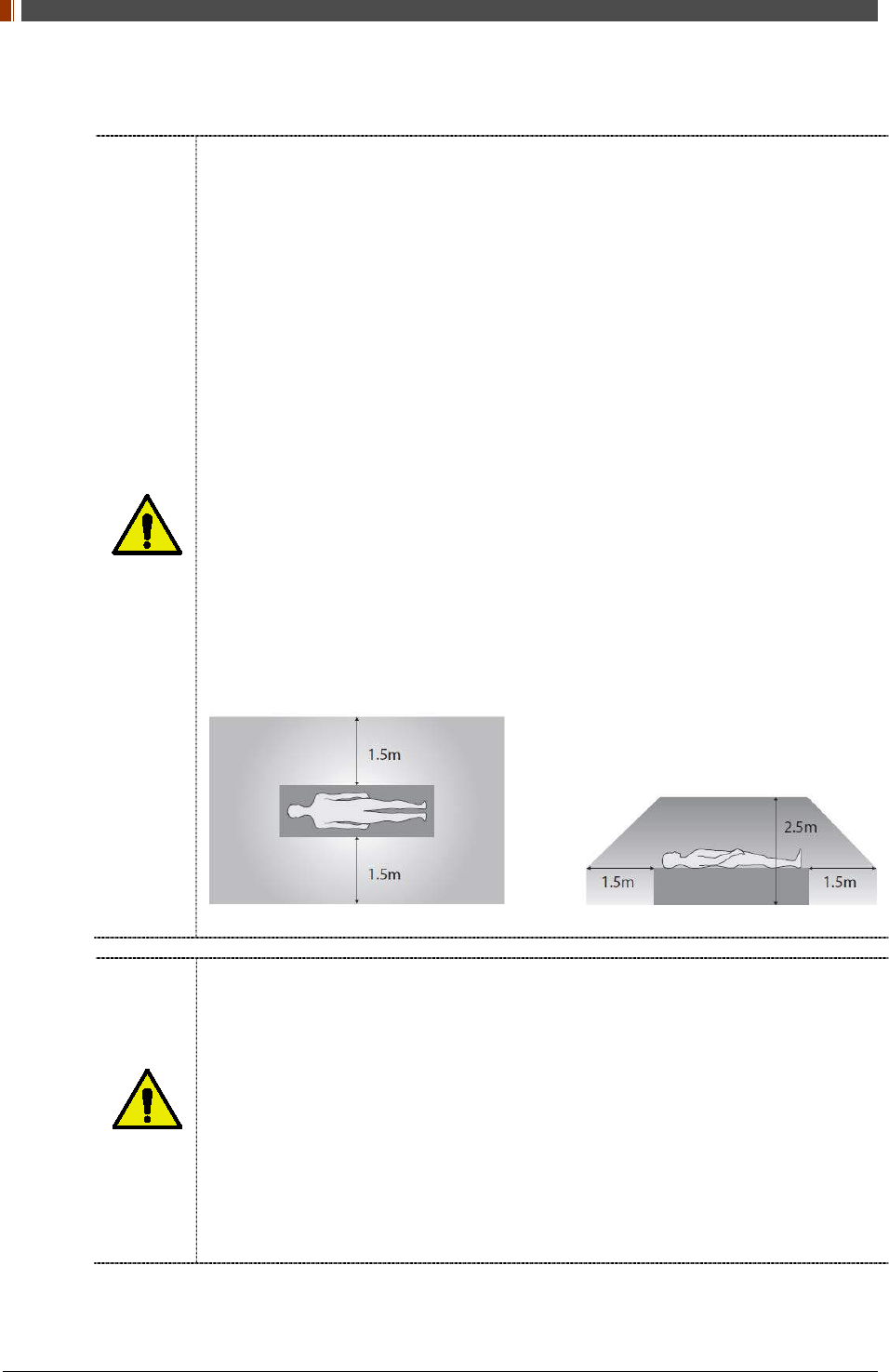
Avoid using co-channel or adjacent-channel with other wireless devices for high quality
wireless performance.
Transmitting omnidirectional radio wave and sending same information to different
place at once is against the law.
Any service related to the human life safety cannot be supported since this wireless
detector has potential electric wave interference.
This wireless detector has potential electric wave interference during use.
PART II. Service Manual
1417WGC/WCC 16
1.4 Caution
CAUTION
Environment of Use and Storage
Do not install the detector in a location with the conditions listed below. Otherwise, it may
result in failure or malfunction, cause fire or injury.
Close to facilities where water is used.
Where it will be exposed to direct sunlight.
Close to air-conditioner or ventilation equipment.
Close to heat source such as a heater.
Prone to vibration
Insecure place.
Dusty environment.
Saline or sulfurous environment.
High temperature or humidity.
Freezing or condensation.
Do not place the storage case in a location with the conditions listed below.
Where the cable of the detector unit will be strongly pulled when the detector is put into
the case, otherwise, the cable may be damaged, resulting in fire or electric shock.
Where someone might get their foot caught in the cable of the detector.
Non-medical equipment such as the battery charger, access point cannot be used in
patient’s vicinity.
CAUTION
Handling
Applied part: CFRP (Carbon Fiber Reinforced Plastic) Applied part having contact with
the patient for a time “t”: 1 min ≤ t < 10 min
If contact over 24 hours on CFRP (Carbon Fiber Reinforced Plastic) of detector, it
could be cause skin irritation.
In order to prevent infection, please wipe the CFRP (Carbon Fiber Reinforced Plastic)
with a soft cloth moistened with IPA (Isopropyl-alcohol) liquid.
Wear waterproof gloves to protect your hands from direct contact with IPA or any other
liquid.
For safety reasons, be sure to turn off the power of each equipment when detector is
not used.
This detector is contraindicated for pregnant woman.
PART II. Service Manual
1417WGC/WCC 17
CAUTION
Location of Cables
Make sure all cables are located so that they cannot be stepped on, tripped over, or
otherwise subjected to damage or stress.
CAUTION
Maintenance and Inspection
For safety reasons, be sure to inspect the detector before using it. In addition, carry out
a regular inspection at least once a year.
If the detector is defective, do not disassemble the detector randomly. Maintenance of
the detector should be done by an authorized service provider. Please contact
Rayence Customer Service team or authorized agent.
Be sure to check the user’s manual for replaceable components.
CAUTION
Modifications
Any changes or modifications in construction of this detector which are not expressly
approved by the party responsible for compliance could void the user’s authority to
operate the detector.
CAUTION
Battery
Do not let the detector or battery come in contact with liquids. Liquids can get into the
detector’s circuits, leading to corrosion. Even when the detector appears to be dry and
appears to operate normally, the circuitry could slowly corrode and pose a safety
hazard. If the battery gets wet, have them checked by authorized agent or contact
Rayence Customer Service team, even if they appear to be working properly.
Do not place your battery near a heat source. Excessive heating can damage the
detector or the battery and could cause the detector or the battery to explode.
Do not dry a wet or damp battery with an appliance or heat source such as a
microwave oven, hair dryer, iron, or radiator.
Do not dispose of the detector or the battery in a fire. The detector or the battery may
explode when overheated.
Use only Rayence-approved batteries and recharge your battery (Model name:
RB37WHA) only with Rayence-approved chargers (Model name: RC120WA) which are
specifically designed for your detector.
Use of a non-Rayence-approved battery or charger may present a risk of fire,
explosion, leakage, or other hazard. Rayence’s warranty does not cover damage to the
detector caused by non-Rayence-approved batteries and/or chargers.
Misuse or use of incompatible batteries and charging detectors could result in damage
to the detector and a possible risk of fire, explosion, or leakage, leading to serious
injuries, damages to your detector, or other serious hazard.
Check the battery status frequently to avoid battery empty. When the low battery LED
of detector is turned on, change the battery or charge the battery using cable.
CAUTION
Recommendations to equipment manufacturers and battery assemblers
The following represents a typical, but non-exhaustive, list of good advice to be
provided by the manufacturer of secondary cells and batteries to equipment
manufacturers and battery assemblers.
Do not dismantle, open or shred cells. Batteries should be dismantled only by trained
personnel. Multicell battery cases should be designed so that they can be opened only
with the aid of a tool.
Do not short-circuit a cell or battery. Do not store cells or batteries haphazardly in a box
or drawer where they may short-circuit each other or be short-circuited by conductive
materials.
Do not remove a cell or battery from its original packaging until required for use.

PART II. Service Manual
1417WGC/WCC 18
Do not expose cells or batteries to heat or fire. Avoid storage in direct sunlight.
Do not subject cells or batteries to mechanical shock.
In the event of a cell leaking, do not allow the liquid to come into contact with the skin
or eyes. If contact has been made, wash the affected area with copious amounts of
water and seek medical advice.
Equipment should be designed to prohibit the incorrect insertion of cells or batteries
and should have clear polarity marks. Always observe the polarity marks on the cell,
battery and equipment and ensure correct use.
Do not mix cells of different manufacture, capacity, size or type within a battery.
Seek medical advice immediately if a cell or battery has been swallowed.
Consult the cell/battery manufacturer on the maximum number of cells, which may be
assembled in a battery and on the safest way in which cells may be connected.
A dedicated charger should be provided for each equipment. Complete charging
instructions should be provided for all secondary cells and batteries offered for sale.
Keep cells and batteries clean and dry.
Wipe the cell or battery terminals with a clean dry cloth if they become dirty.
Secondary cells and batteries need to be charged before use. Always refer to the cell
or battery manufacturer’s instructions and use the correct charging procedure.
Do not maintain secondary cells and batteries on charge when not in use.
After extended periods of storage, it may be necessary to charge and discharge the
cells or batteries several times to obtain maximum performance.
Secondary cells and batteries give their best performance when they are operated at
normal room temperature.
Retain the original cell and battery literature for future reference.
When disposing of secondary cells or batteries, keep cells or batteries of different
electrochemical systems separate from each other.
Contact the Rayence Customer Service team to destroy a battery.
PART II. Service Manual
1417WGC/WCC 19
CAUTION
Recommendations to the end-users
The following represents a typical, but not exhaustive list of good advice to be provided
by the equipment manufacturer to the end-user.
Do not dismantle, open or shred secondary cells or batteries.
Do not expose cells or batteries to heat or fire. Avoid storage in direct sunlight.
Do not short-circuit a cell or a battery. Do not store cells or batteries haphazardly in a
box or drawer where they may short-circuit each other or be short-circuited by other
metal objects.
Do not remove a cell or battery from its original packaging until required for use.
Do not subject cells or batteries to mechanical shock.
In the event of a cell leaking, do not allow the liquid to come in contact with the skin or
eyes. If contact has been made, wash the affected area with copious amounts of water
and seek medical advice.
Do not use any charger other than that specifically provided for use with the
equipment.
Observe the plus (+) and minus (–) marks on the cell, battery and equipment and
ensure correct use.
Do not use any cell or battery which is not designed for use with the equipment.
Do not mix cells of different manufacture, capacity, size or type within a device.
Keep cells and batteries out of the reach of children.
Seek medical advice immediately if a cell or a battery has been swallowed.
Always purchase the correct cell or battery for the equipment.
Keep cells and batteries clean and dry.
Wipe the cell or battery terminals with a clean dry cloth if they become dirty.
Secondary cells and batteries need to be charged before use. Always use the correct
charger and refer to the manufacturer’s instructions or equipment manual for proper
charging instructions.
Do not leave a battery on prolonged charge when not in use.
After extended periods of storage, it may be necessary to charge and discharge the
cells or batteries several times to obtain maximum performance.
Secondary cells and batteries give their best performance when they are operated at
normal room temperature (20 °C ± 5 °C).
Retain the original product literature for future reference.
Use only the cell or battery in the application for which it was intended.
When possible, remove the battery from the equipment when not in use.
Dispose of properly.
Contact the Rayence Customer Service team to destroy a battery.
PART II. Service Manual
1417WGC/WCC 20
1.5 Safety Information
Preparation
Be sure to connect the cables to the proper connectors. Otherwise, the detector may
malfunction or may be damaged.
The power supply provided by Rayence is designed for the detector from Rayence. Please
contact Rayence, if any other type of power supply is needed to be used.
Be sure to fully charge the battery before use. Charge the battery on the day of examination
or on the previous day.
Battery slowly discharges even when not in use. The battery may have expired if it
discharges immediately after being fully charged. You can purchase an optional battery to
replace an exhausted one.
The battery charger provided by Rayence is designed for the dedicated battery.
When the detector will not be used for some time, remove the battery.
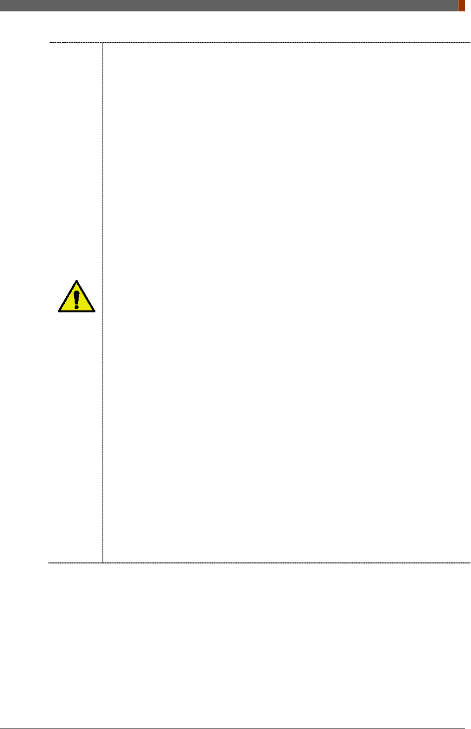
Handling
Handle the detector carefully, as it may become damaged if it is hit, dropped, or receives a
strong jolt.
Be sure to use the detector on a flat place so it will not bend. Otherwise, the detector may
be damaged.
PART II. Service Manual
1417WGC/WCC 21
Be sure to check the detector daily and confirm that it works properly. Sudden heating of
the room in cold areas will cause condensation to form on the detector. In this case, wait
until condensation disappears before performing exposure. If the detector is used with
condensation formed on it, problems may occur in the quality of the detector. When an air-
conditioner is going to be used, be sure to raise/lower the temperature gradually so that a
difference in temperature in the room and in the detector does not occur, to prevent forming
of condensation. Follow the recommended proper Room temp.
Do not use the detector near devices generating a strong magnetic field. Doing so may
produce image noise or artifacts.
Keep the connectors free from being in contact with the patient.
Connectors are intended to be connected to an external device and must follow IEC
standards.
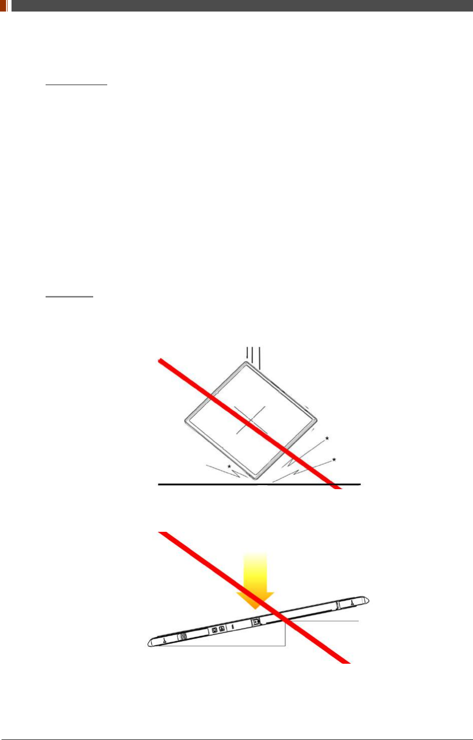
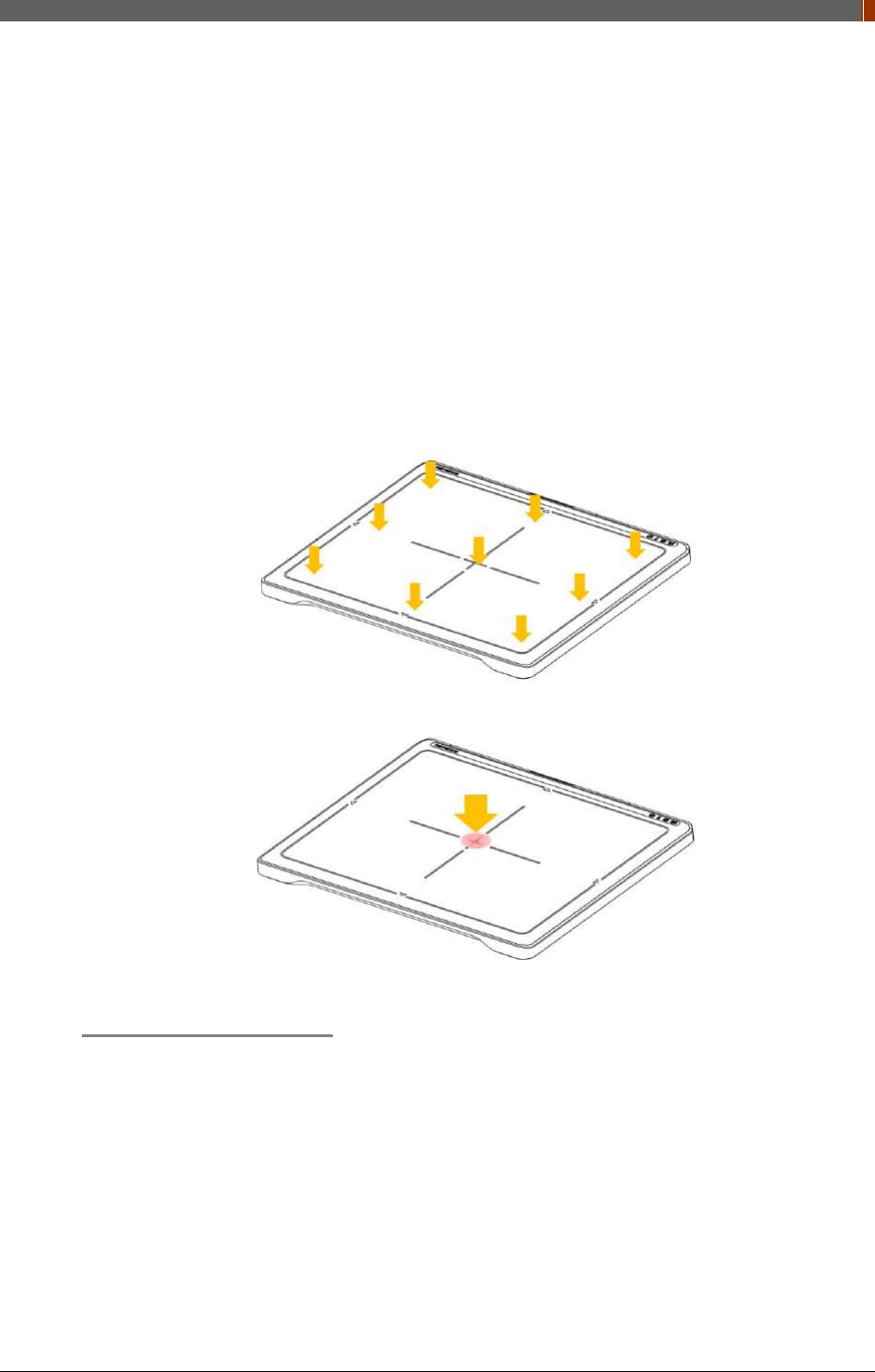
Do not apply excessive weight to the detector. Otherwise, the detector may be damaged.
Overall Pressure: 300kg(661lb) over the whole area of detector window.
Partial Pressure: 150kg(330lb) on an area 40 mm in diameter.
Disinfection and Cleaning
Do not spray disinfectants or detergents on the detector.
When cleaning the detector, be sure to turn off the power, and unplug the power cable from
the AC outlet.
Do not use any flammable chemicals such as thinner, benzene for cleaning. Otherwise, fire
or electric shock may result.
Wear waterproof gloves to protect your hands from direct contact with disinfectants or
detergents.

PART II. Service Manual
1417WGC/WCC 22
1.6 Label and Location of Attachment
Refer to the back of the device for details.
1.7 Summary of usability specifications
Medical purposes
Provision and reading of disease and injury diagnostic images
Patient groups
No patient population exists who uses or is in contact with the device.
Patient population for the X-ray images read is not specified.
Parts of body or organizations to which the device is mounted or that interact
with the device
Detector contacts the body surface of a patient and an operator.
Significant physical and performance characteristics
Refer to 2.4 Part Specifications in this manual
Operating principles
Flat panel detector is a system that can acquire, save, process and transfer digital images
of an area of interest taken with X-ray. X-ray beam entering the X-ray imaging sensor is
converted into visible light by scintillation layer of the sensor. The amorphous silicon (a-Si)
and Photo Diode on TFT Array of the sensor further converts visible light into electric signal.
Electric signals are amplified and converted to digital signals to form image data.
Obtained image data is transferred to the computer via Ethernet or Wi-Fi interface and
visually displayed on the monitor screen.
Intended user profile
No special training is required to use this device. The intended users of this device are as
follows.
A professional in good health with specialist knowledge/ qualifications who has fully understood
the content of this document. (Such as a doctor or radiological technologist)

PART II. Service Manual
1417WGC/WCC 23
2. Product Introduction and Specification
2.1 Product Features
The 1417WGC/WCC are wireless digital flat panel detectors that has been designed for a
faster, more streamlined approach to digital radiography systems.
The 1417WGC/WCC detector contains a built-in Access Point (AP) enabling images to be
directly sent to a Wi-Fi connected computer within seconds. Built-in image memory storage
permits taking images where a computer connection is not available and also prevents lost
images should there be an interruption of power. Whether an image was taken with the detector
in the portrait or landscape position, the auto image rotation function allows images to be
displayed in the correct orientation.
These features, coupled with an auto-trigger signal sensing technology that allows the detectors
to be used without generator integration, makes the 1417WGC/WCC the ideal flat panel
detector solutions for both fixed and portable applications.

PART II. Service Manual
1417WGC/WCC 24
2.2 Product Components
2.2.1 Basic Components
Detector 1EA Battery 2EA Charger Adaptor 1EA &
Mobile charger adaptor 1EA
AC power cord 1EA
(110V or 220V 1.8m)
Installation CD 1EA Manual 1EA
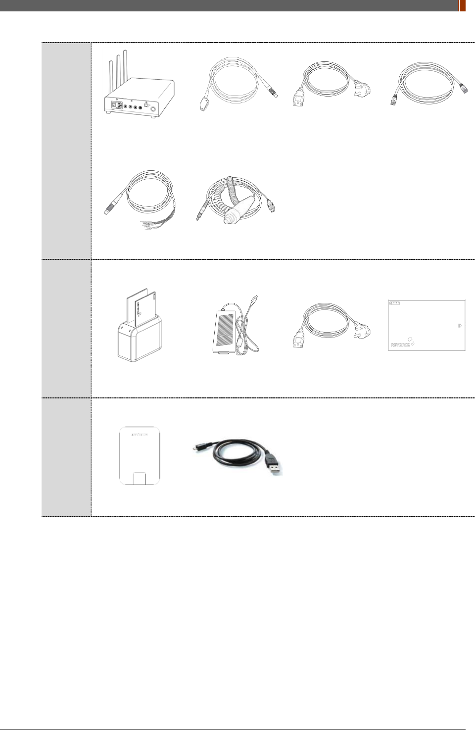
2.2.2 Optional Components
Power
supply
package
Power supply1EA AC power cord 1EA
(110V or 220V 1.8m)
LAN cable 1EA
(CAT 6, 10m)
(straight-through)
Link Cable 1EA
(7, 9m)
AGI
package
Trigger Cable 1EA P-interface Cable
1EA AGI Box 1EA USB Cable 1EA
PART II. Service Manual
1417WGC/WCC 25
Interface
box
package
RAP001A Link Cable 1EA
(7, 9m)
AC power cord 1EA
(110V or 220V 1.8m)
LAN cable 1EA
(CAT 6, 10m)
(straight-through)
Trigger Cable 1EA P-interface Cable
1EA
Battery
Charger
Package
Battery Charger 1EA Battery Charger
adapter 1EA
AC power cord 1EA
(110V or 220V 1.8m) Battery 2EA
Sharing
Package
IrDA module 1EA Micro USB cable
1EA
PART II. Service Manual
1417WGC/WCC 26
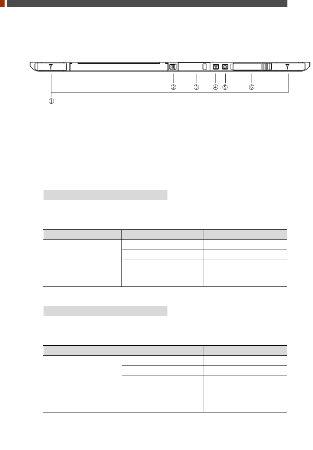
2.3 Part Names and Functions
2.3.1 Detector
1. Wireless Antenna
2. Battery Unlock button
This is an unlock button to remove battery
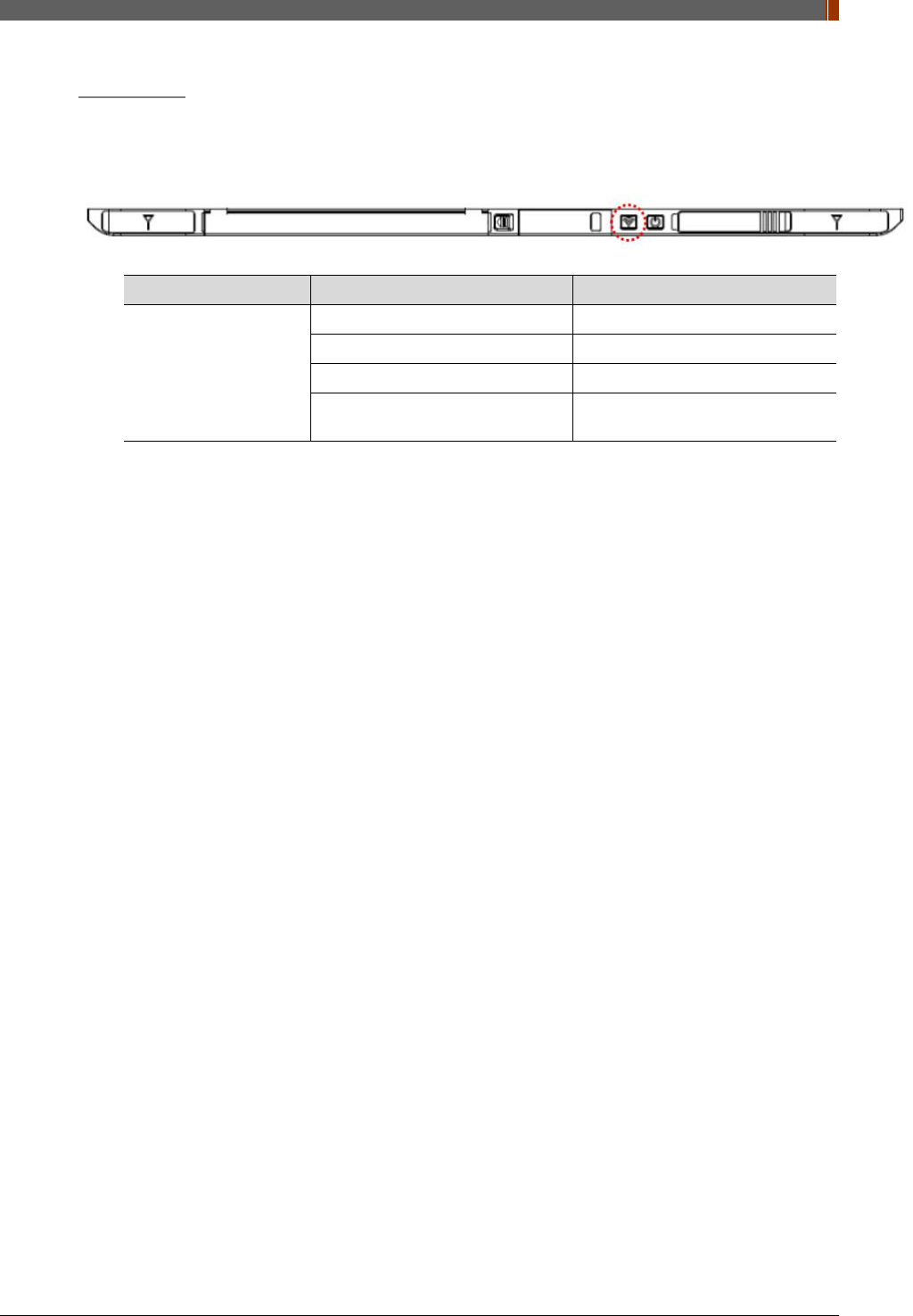
3. IrDA & OLED window
IrDA module can communicate with infrared ray and inform the product status.
4. Mode select button & LED indicator
Mode Change
Press the 1 second
Indication the status of detector
Name of LED Status of LED Status of product
Mode
Orange on Station mode(wireless)
Green on AP mode(wireless)
Off Wired mode
Blinking Orange and Green
alternatively Sleep mode
5. Power button & LED indicator
Power On / Off
Press over than 3 seconds
Indicating the status of detector
Name of LED Status of LED Status of product
Power
Green Power on
Blinking green Power booting
Red Low battery
(Battery remain 0~7%)
Orange Low battery
(Battery remain 7~15%)
PART II. Service Manual
1417WGC/WCC 27
6. Link cable connector
Use for data transfer and charging battery while wired mode is in use (Connect between
detector and power supply.)
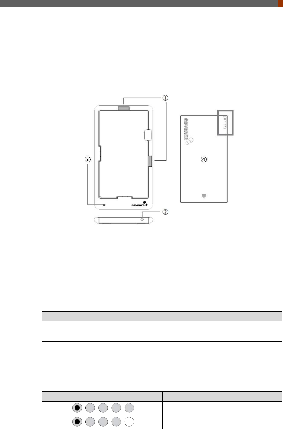
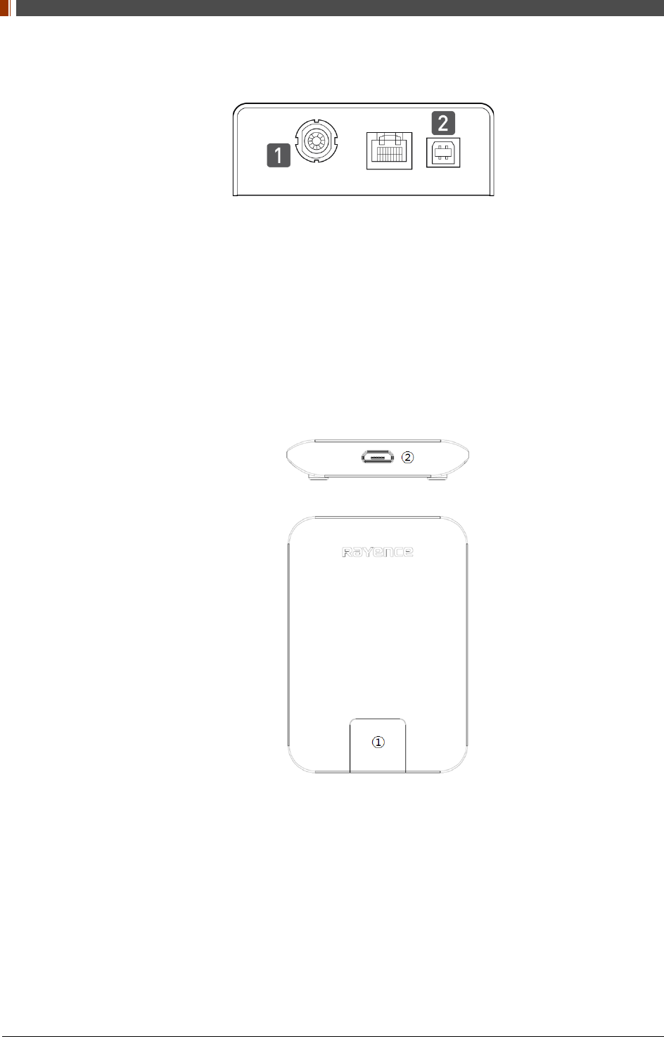
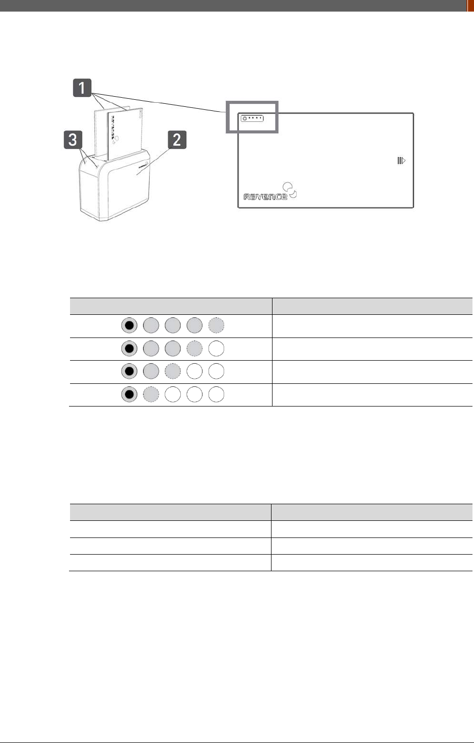
2.3.2 Battery & Mobile charger
1. Battery unlock level
This is an unlock-level to remove battery
2. Power connector
Connects to the mobile charger adapter
3. LED Indicator
Display battery charging status.
LED Color Battery Status
Green Fully charged
Orange Charging
Blinking orange and Green alternatively Error
4. Battery : Rechargeable Lithium Ion battery(Charging Time-3 hrs)
• In the diagram above, the box shows where the remaining battery percentage is
displayed.
Battery Remain Indicator Battery Level
75~100 %
50~75 %
PART II. Service Manual
1417WGC/WCC 28
Battery Remain Indicator Battery Level
25~50 %
0~25 %
• Battery warranty period: 6 months
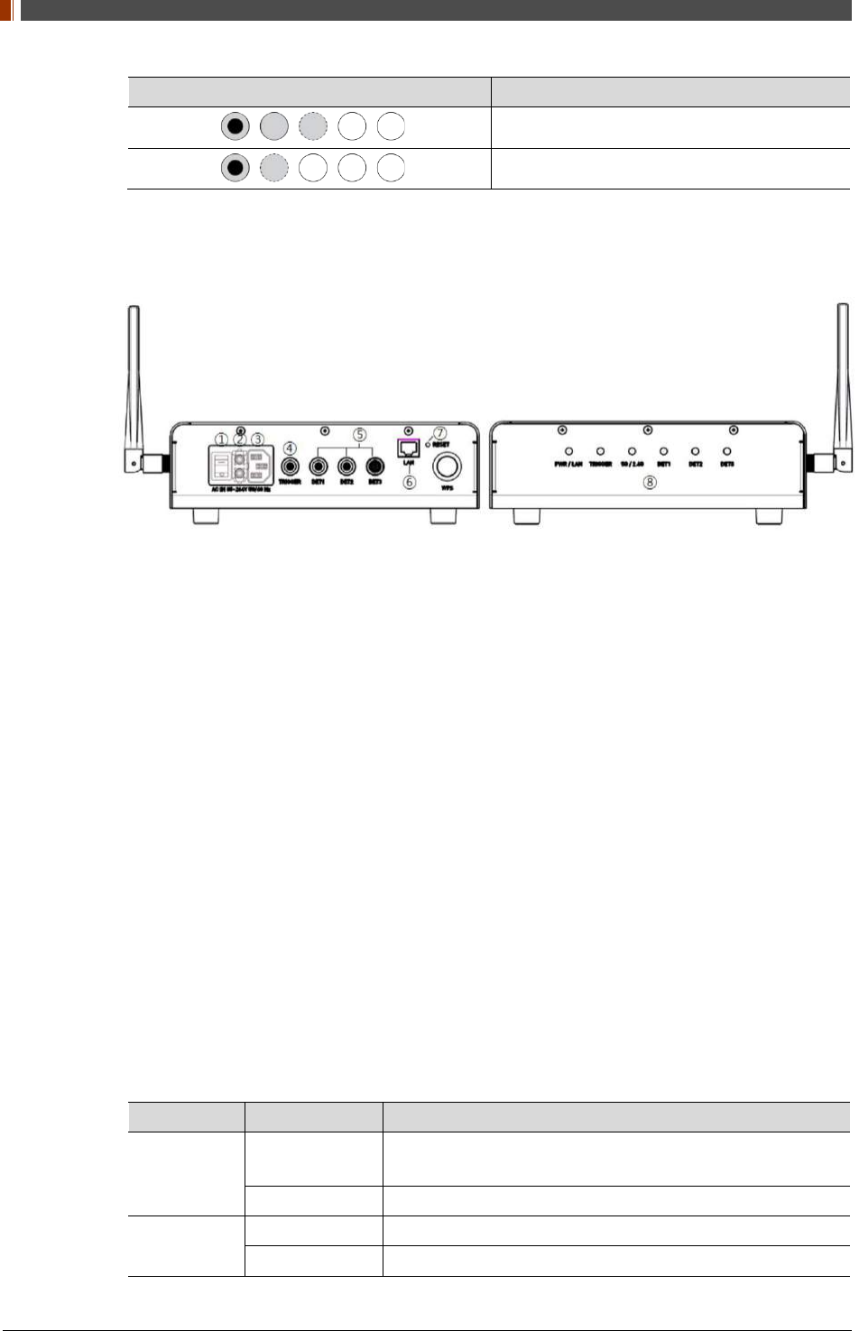
2.3.3 RAP001A (Optional)
1. Switch
Power On/Off switch
2. Fuse
T3.15 AL 250V
3. Power plug connector
Connects to the AC power cord
4. Trigger connector
This is a connector to synchronize the detector and generator. Connect the RAP001A to the
generator by using a P-interface cable or trigger cable.
5. Link connector 1~3
Use for data transfer and charging battery while detector is in use (Connect between
detector and RAP001A), Up to three detector can be connected
6. LAN connector
Ethernet port for transmitting an image/command between the detector and PC
7. Reset button
Reset all settings to default values
8. Indicating the status of RAP001A
LED LED Color Status
PWR/LAN Red Turned on while booting after connecting with power supply.
Turned off upon the completion of booting.
Blinking Green Connected with PC LAN
TRIGGER Red Trigger READY DONE
Green Trigger READY IN
PART II. Service Manual
1417WGC/WCC 29
LED LED Color Status
5G/2.4G
Red Frequency of 2.4GHz
Green Frequency of 5GHz
Yellow Frequency of 2.4GHz and 5GHz
DET1 Green Connected with detector of port1
DET2 Green Connected with detector of port2
DET3 Green Connected with detector of port3
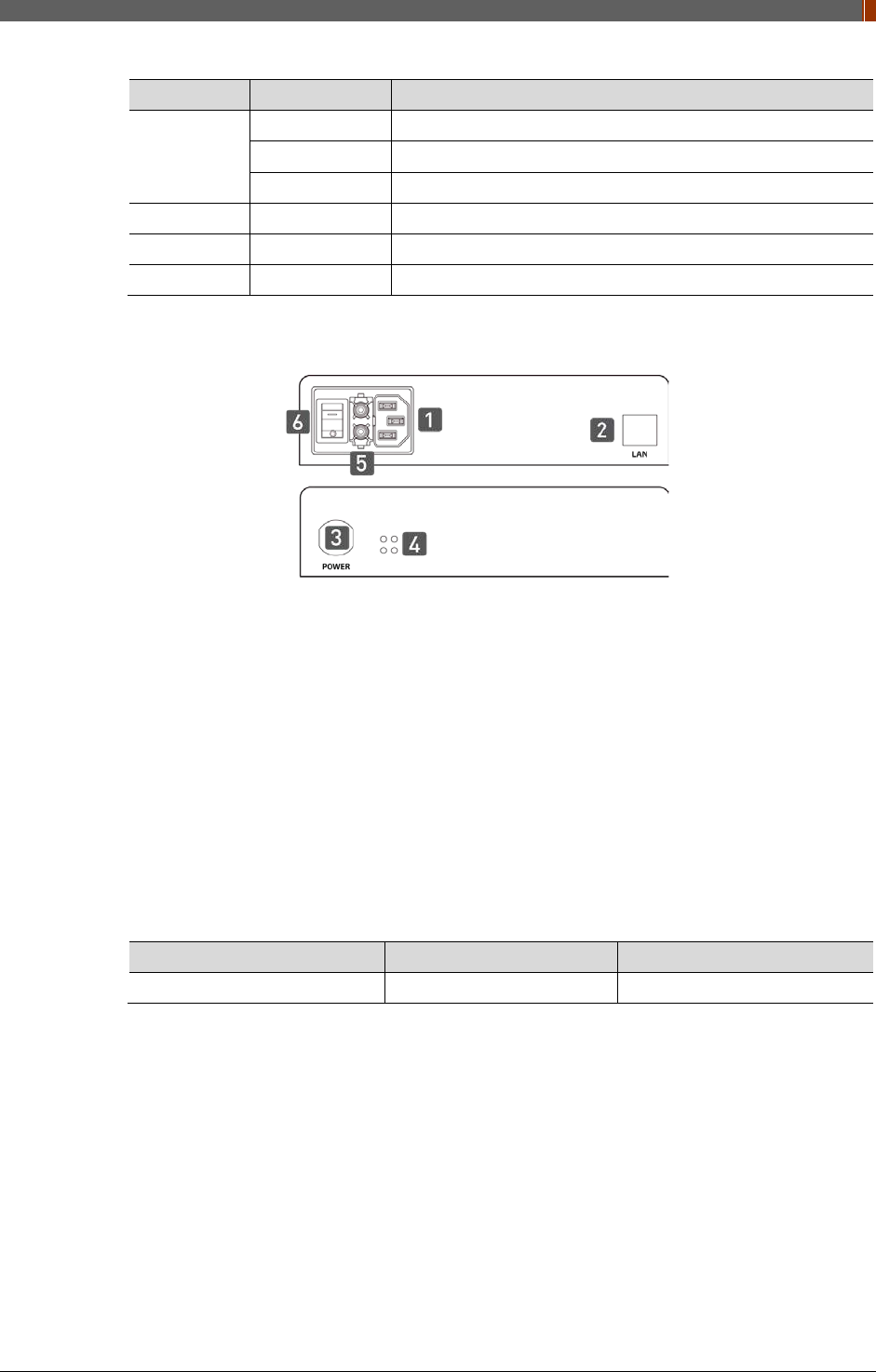
2.3.4 Power Suppy (Optional)
1. Power Plug Connector
Connects to the AC power cord
2. LAN Connector
Ethernet port for transmitting an image/command between the detector and PC
3. Link Connector
Used for charging the battery while the detector is in use (Connect the detector and power
supply)
4. LED Indicator
Display status of the power supply.
Color Status Power Status
Green On Power on
5. Fuse
T3.15 AL 250V
6. Switch
Power On/Off switch
PART II. Service Manual
1417WGC/WCC 30
2.3.5 AGI Box (Optional)
7. Trigger Connector
This is a connector to synchronize the detector and generator. Connect the AGI to the
generator by using a P-interface cable or trigger cable.
8. USB Connector
This is a connector for communication between the AGI and PC. Connect the AGI to the PC
by using a USB cable.
2.3.6 IrDA module (Optional)
1. IrDA window
Window for communicating intrared with Detector
2. Micro USB connector
Connector for communication with IrDA and PC connect the PC through the Micro USB
cable.
PART II. Service Manual
1417WGC/WCC 31
2.3.7 Battery & Charger (Optional)
1. Battery : Rechargeable Lithium Ion battery(Charging Time-3 hrs)
• In the diagram above, the box shows where the remaining battery percentage is
displayed.
Battery Remain Indicator Battery Level
75~100 %
50~75 %
25~50 %
0~25 %
• Battery warranty period: 6 months
2. Battery Charger : Two port cradle type
3. LED Indicator
Display battery charging status.
LED Color Battery Status
Green Fully charged
Orange Charging
Red Error

PART II. Service Manual
1417WGC/WCC 32
2.4 Part Specifications
2.4.1 Detector
Parameter Spec. Unit
Sensor Type Amorphous Silicon with TFT (Single panel) -
Scintillator Type 1417WCC_127/140: CsI:Tl
1417WGC_127/140: Gd2O2S:Tb -
Total Pixel Matrix 127type: 3328 X 2816
140type: 2500 X 3052 Pixels
Total Pixel Area 127type: 422.7 X 357.6
140type: 350.0 X 427.3 mm
Pixel Pitch 127type: 127
140type: 140 μm
Effective Pixel Matrix 127type: 3268 X 2756
140type: 2440 X 2992 Pixels
A/D Conversion 14 / 16 bits
Data Transfer
1Gbps Ethernet
802.11 a/g/n Wireless LAN, Wireless LAN up to
867Mbps
-
Preview time ≤2 (2x2 binning) sec
Energy range 40 ~ 150 kVp
Limiting Resolution 127 type: Min.2.5/ Max. 3.93
140 type: Min.2.5/ Max. 3.57 lp/mm
MTF (@1lp/mm)
1417WCC_127 - Min. 50 / Typ. 59
1417WCC_140 - Min. 50 / Typ. 57 %
1417WGC_127 - Min. 50 / Typ. 57
1417WGC_140 - Min. 50 / Typ. 55
DQE (@0.1lp/mm)
1417WCC_127 - Min 50 / Typ. 65
1417WCC_140 - Min. 50 / Typ. 65 %
1417WGC_127 -Min. 36 / Typ. 45
1417WGC_140 - Min. 36 / Typ. 45
Dimension 460 x 384 x 15 mm
Weight 3 (incl. battery) Kg
Sensor Protection Material Carbon fiber plate -
Trigger mode Manual Mode
Auto Trigger Mode (Auto Exposure Detection) -
Power consumption Typ. 8.8 w
Wireless specifications
Standard
802.11 a/g/n compliance
Without DFS (5.25GH to 5.35GHz
and 5.47 to 5.725) Band
Peak Rate 1300Mbs
Frequency 2.4 GHz / 5GHz
Bandwidth 20MHz / 40MHz

PART II. Service Manual
1417WGC/WCC 33
Parameter Spec. Unit
MIMO 2 X 2
Maximum wireless signal rate derived from IEEE standard specifications. Actual data
throughput will vary. Network conditions and environmental factors, including volume of
network traffic, building materials and construction, and network overhead, lower actual
data throughput rate.
Recommended Maximum operable distance : 10m (From the Access Point)
Wireless Module and Wireless Antenna
• Wireless antennas: The module adopts the latest 802.11n Dual-Band technology
(2.4Ghz and 5Ghz). The transmitter of the module is powered by host equipment
(Detector). The antennas are 2 printed-dipole antennas.
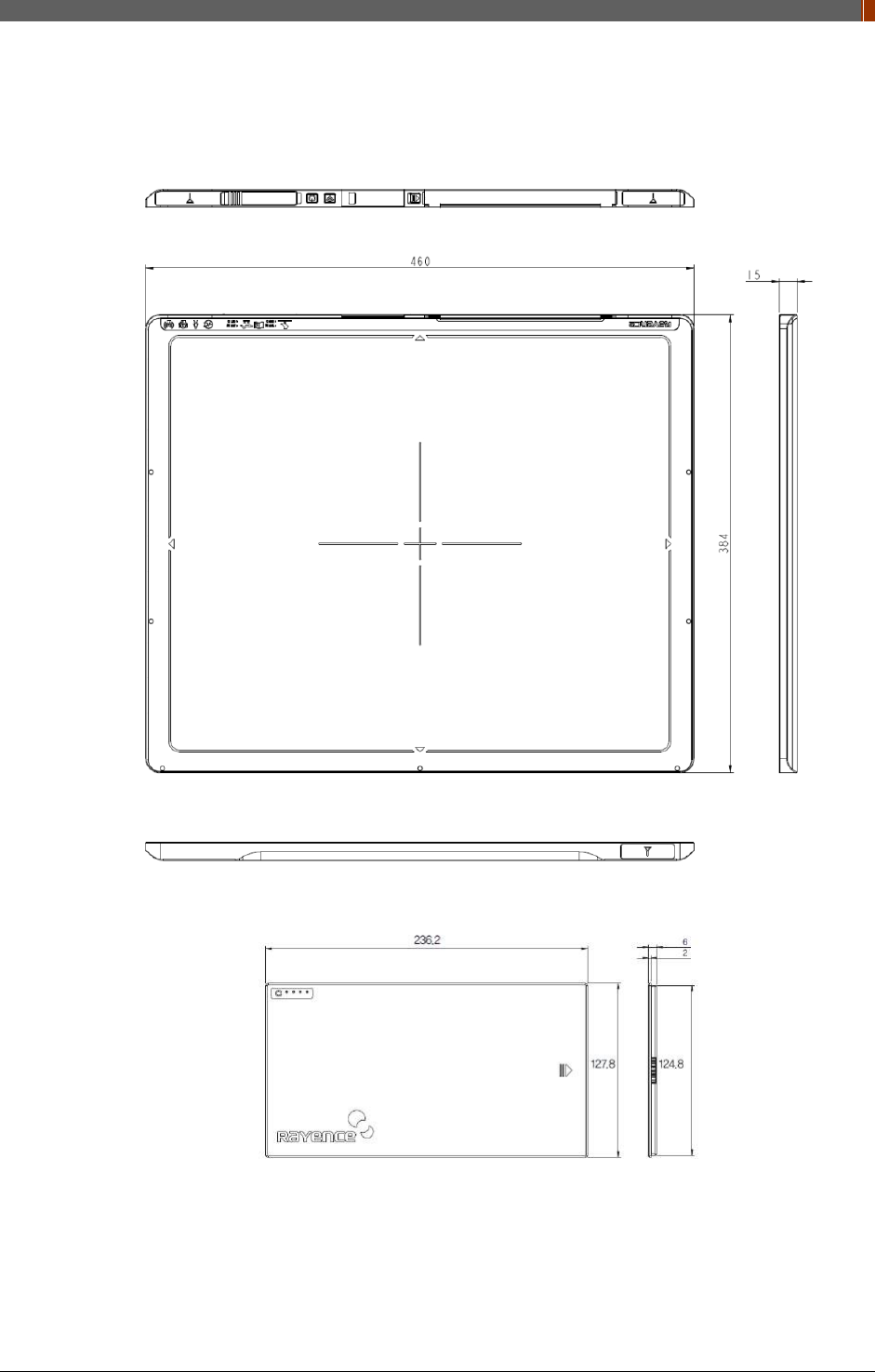
2.4.2 Battery [Model name: RB37WHA]
Parameter Spec. Unit
Size 236.2 x 127.8 x 6 mm
Weight 0.3 Kg
Input 12.6 VDC
Output 11.1 VDC
Cycle life Max. 500 cycles
Operation temp. range 5~40 ℃
Charging time Typ. 3 hours
Capacity Typ. 3400 mAh
Operating time Typ. 4 hours
2.4.3 Mobile charger [Model name: RMC001A]
Parameter Spec. Unit
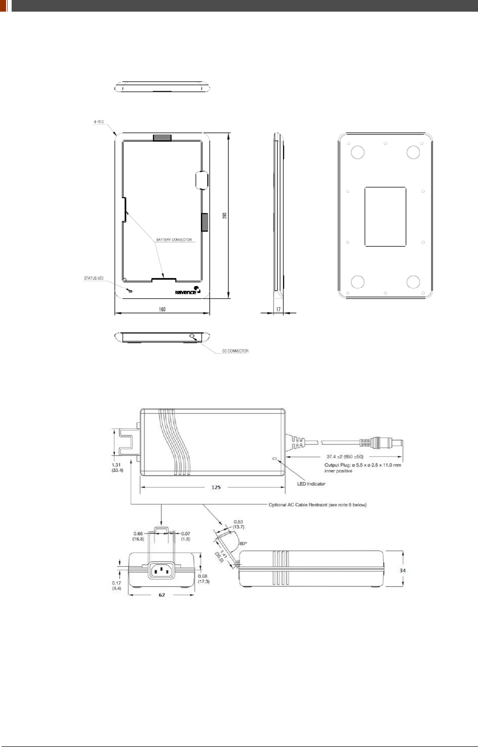
Dimension 280 X 160 X 17 mm
Weight 0.3 Kg
Input 18 VDC
Output 12.6 VDC
2.4.4 Mobile charger Adaptor [Model name: AFM60US18]
Parameter Spec. Unit
Dimension 125 X 62 X 34 mm
Weight 0.4 Kg
Input 80-264VAC, 47~63Hz, 1.5A -
Output 18VDC, Max 3.34A -

PART II. Service Manual
1417WGC/WCC 34
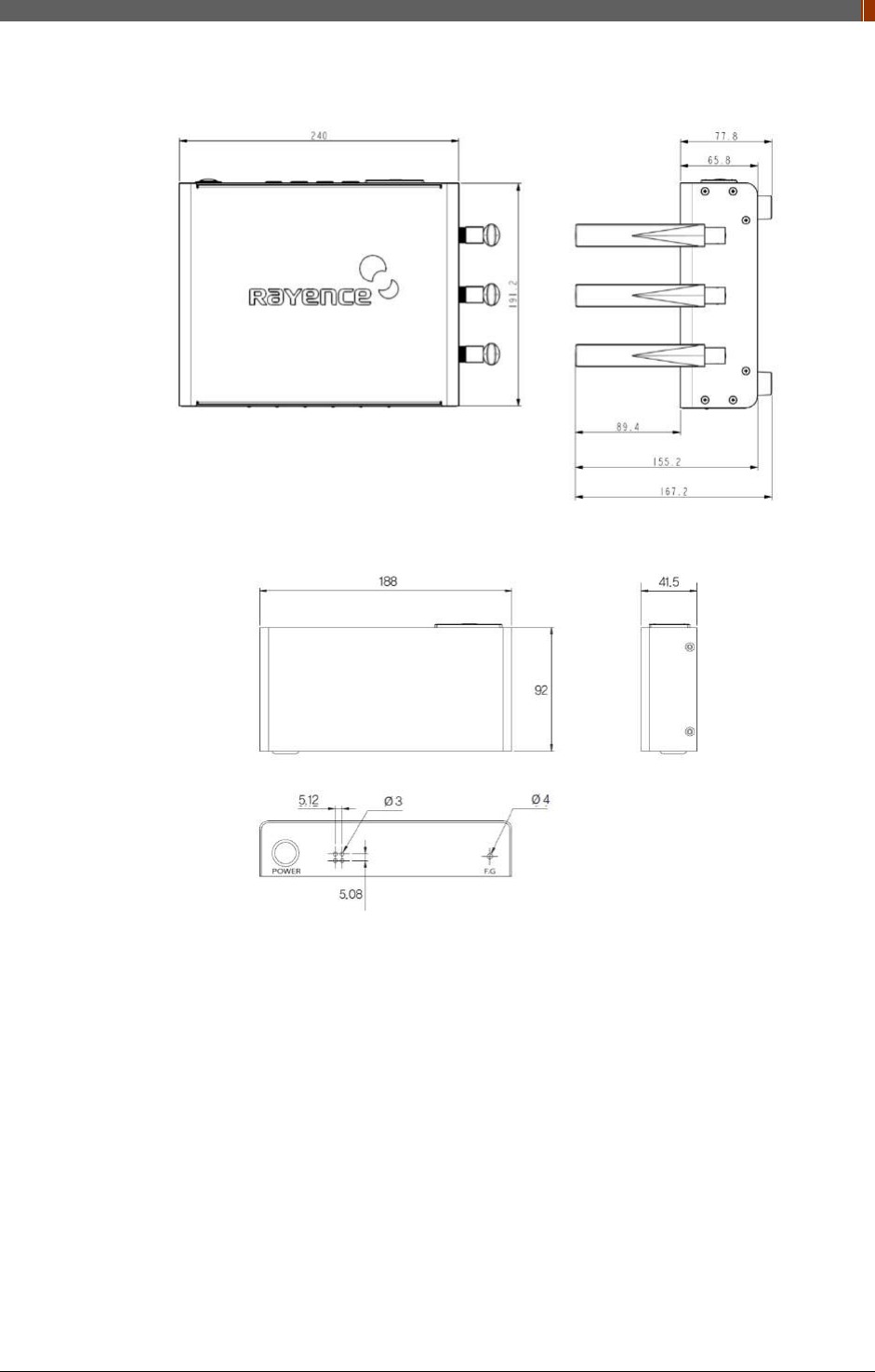
2.4.5 Interface box (Optional) [Model name: RAP001A]
Parameter Spec. Unit
Dimension 240 X 191.2 X 65.8 (not incl. antenna) mm
Weight 1.85 Kg
Input rate 85 ~ 264VAC (50/60Hz) -
Output Typ. 24VDC (Max 5.4A)
Wireless communication 802.11 a/g/n Wireless LAN, up to 867Mbps -
Wired communication Ethernet 1Gbps
Detector Port 3
Trigger Port 1
2.4.6 Power Supply (Optional) [Model name -RP003A]
Parameter Spec. Unit
Dimension 188 X 92 X 41.5 mm
Weight 0.5 Kg
Rated power supply(Input) 100-240VAC (50/60Hz) -
Rated power supply(Output) Typ. 24VDC (Max 1.6A) -
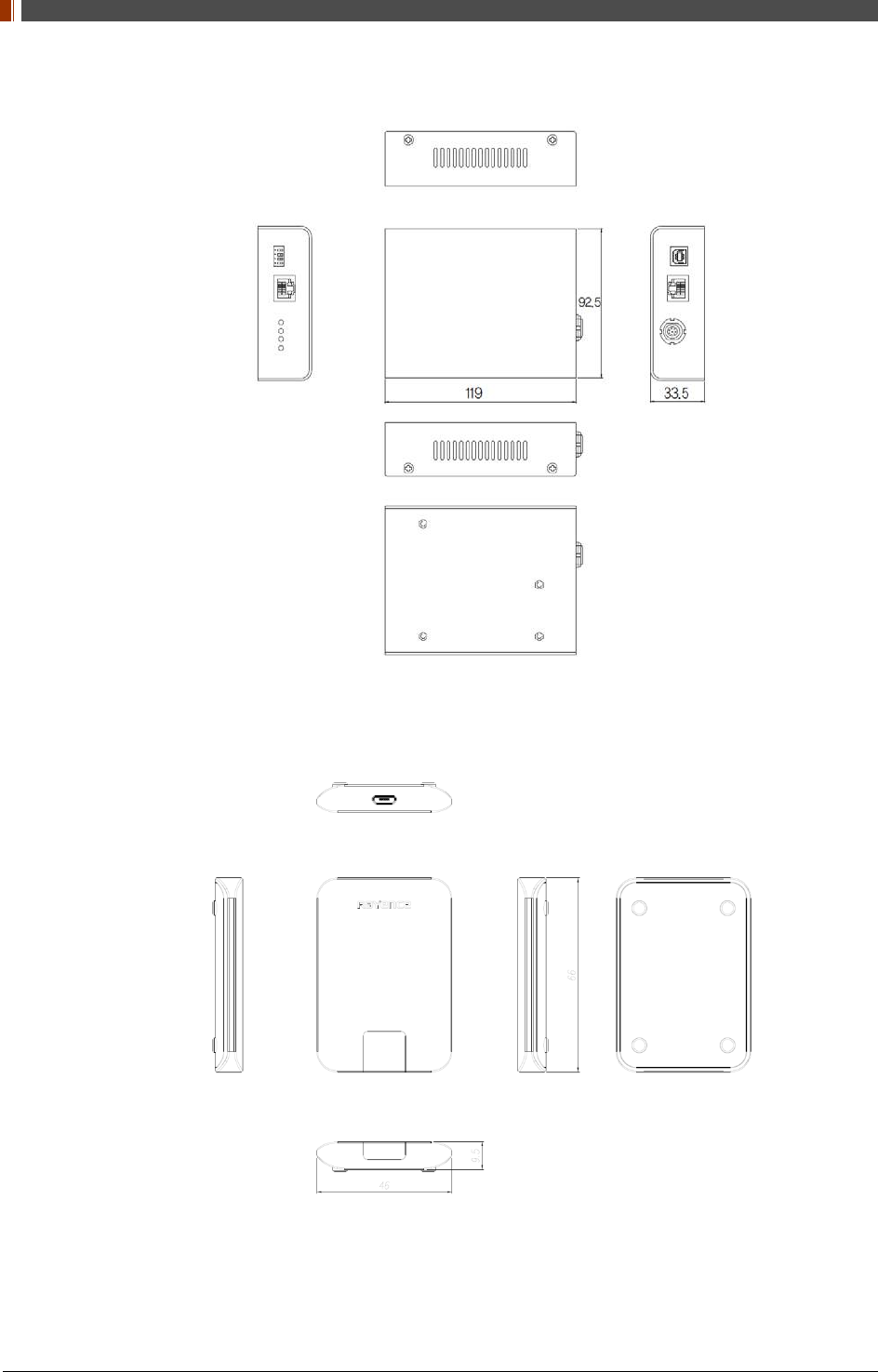
2.4.7 AGI Box (Optional)
Parameter Spec. Unit
Dimension 92.5 X 119 X 33.5 mm
Weight 0.3 Kg
2.4.8 IrDA module (Optional) [Model name – RI001A]
Parameter Spec. Unit
Dimension 66 X 46 X 9.5 mm
Weight 0.1 Kg
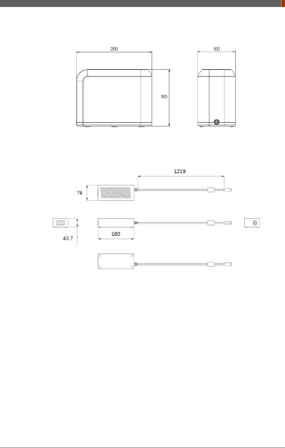
2.4.9 Battery Charger (Optional) [Model name: RC120WA]
Parameter Spec. Unit
Size 200 x 100 x 150 mm
Weight 0.9 Kg
Input 20 VDC
Output 12.6 VDC
2.4.10 Battery Charger Adapter (Optional) [Model name: PMP120-13-3]
Parameter Spec. Unit
Size 160 x 76 x 43.7 mm

PART II. Service Manual
1417WGC/WCC 35
Parameter Spec. Unit
Weight 0.8 Kg
Input 100-240VAC, 47~63Hz, 1.4~0.6A -
Output 20VDC, Max 6.0A -
2.4.11 Cable
Parameter Length Unit
Link cable (Optional) 7 up to 9 m
LAN cable
(CAT 6(straight-through), Optional) 10 m
Power cord (110V or 220V) 1.8 m
USB cable (Optional) 1.8 m
Trigger cable (Optional) 10 m
P-interface cable (Optional) 8 m
Micro USB cable (Optional) 1 m
PART II. Service Manual
1417WGC/WCC 36
2.5 Environmental Requirements
2.5.1 PC Requirement
Item Detail
CPU At least Intel Pentium IV HT with 2.8GHz, Intel Core Duo / Core 2 or
comparable AMD Dual Core processor
RAM At least 3GB of RAM requirement
(4GB for 32 BITS OS and 8GB for 64 BITS OS recommended)
Capacity of Disk Drive At least 500GB for application and archiving. Recommended 500GB for
applications and secondary drive of 1TB for image archiving.
Network Card
Dual 10/100/1000 network card system required. One for network
(Internet) and one for the DR Panel communication
802.11 a/g/n Wireless LAN card required (optional)
Graphic Card / Monitor Graphics card / monitor: Resolution of at least 1,600 x 900 for desktop and
1366 x 768 for laptop. For diagnostics purpose we recommend 1920 x
1080 resolution (2 mega pixels) monitor
Operating System(OS) MicrosoftⓇ Windows XP/VISTA/7/8/10 32BIT/64BIT
ETC No antivirus except for MicrosoftⓇ Security Essentials.
2.5.2 Environmental Requirement
Environment Min. Typ. Max. Unit Note
Temperature(Storage) -10 50 ℃
Temperature(Operation) 5 35 ℃
Humidity(Storage) 10 80 % H.R.
Humidity(Operation) 30 75 % H.R.
Pressure(Operation) 70 106 kPa
2.5.3 Grid Requirement
127um
Item Description
SID 100/130/180 cm
Ratio 8:1
Frequency 230 Line/inch
139um
Item Description
SID 100/130/180 cm
Ratio 8:1
Frequency 215 Line/inch
PART II. Service Manual
1417WGC/WCC 37
2.6 Dimensions (Unit: mm)
2.6.1 Detector
2.6.2 Battery
PART II. Service Manual
1417WGC/WCC 38
2.6.3 Mobile charger
2.6.4 Mobile charger adapter
PART II. Service Manual
1417WGC/WCC 39
2.6.5 Interface box (Optional)
2.6.6 Power Supply (Optional)
PART II. Service Manual
1417WGC/WCC 40
2.6.7 AGI Box (Optional)
2.6.8 IrDA module (Optional)
PART II. Service Manual
1417WGC/WCC 41
2.6.9 Battery Charger (Optional)
2.6.10 Battery Charger Adapter (Optional)
PART II. Service Manual
1417WGC/WCC 42
3. Installation and Calibration
3.1 Installation
3.1.1 Software Installation
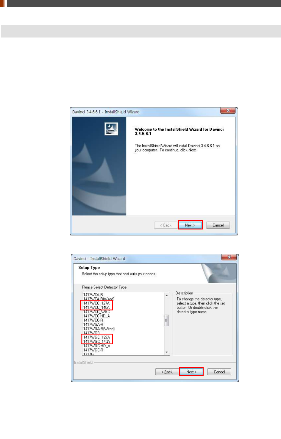
1. Insert the CD that comes with the Detector.
2. Install "setup.exe" from "\Release Davinci_version" and click "Next".
3. Choose the model from the Detector Type list and click "Next".
PART II. Service Manual
1417WGC/WCC 43
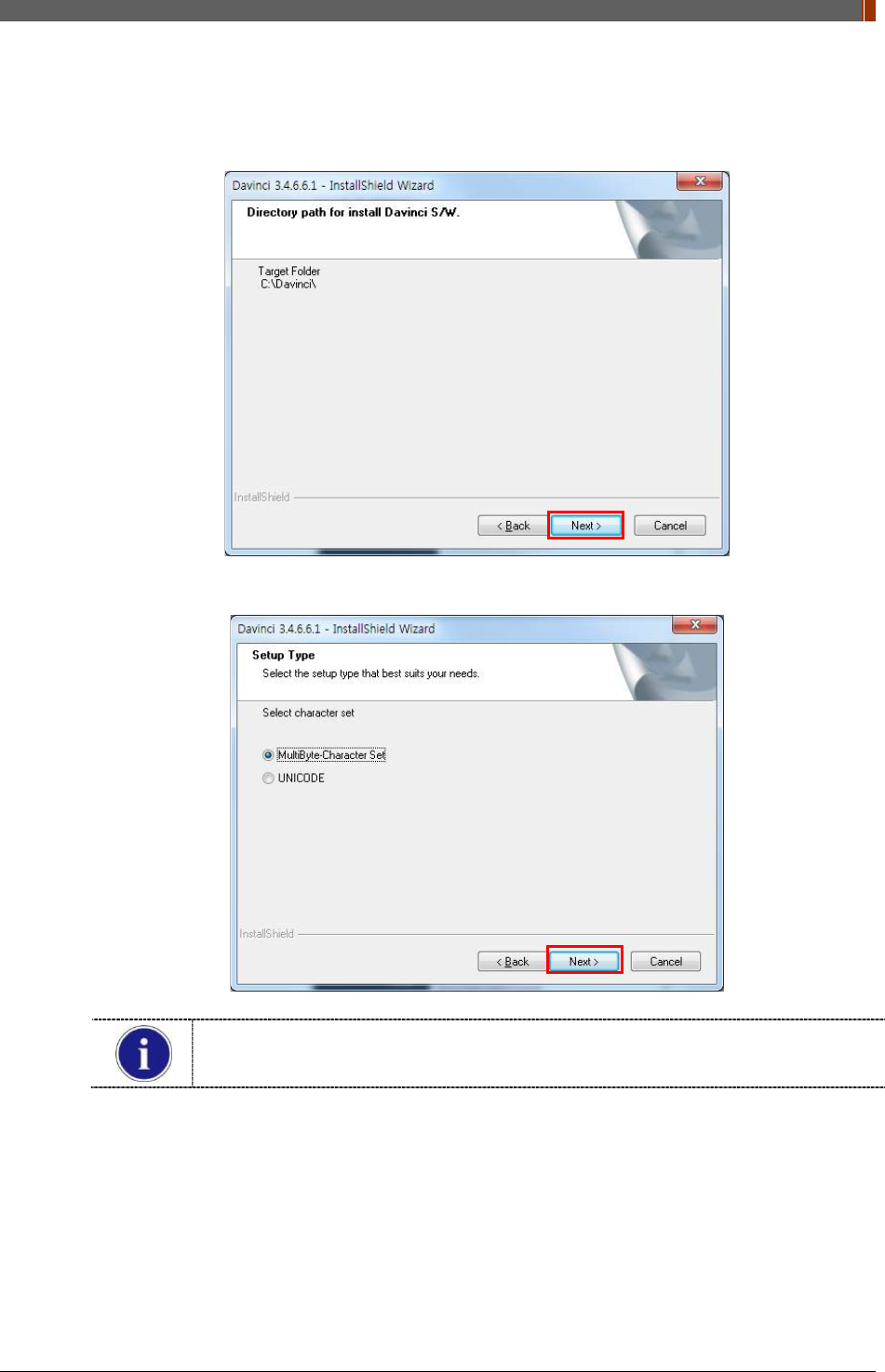
4. Click “Next”.
5. Select “MultiByte-Character Set” and click “Next”.
Choose UNICODE if console SW is supporting UNICODE.
If Character set is not installed correctly, images will not be properly acquired.
PART II. Service Manual
1417WGC/WCC 44
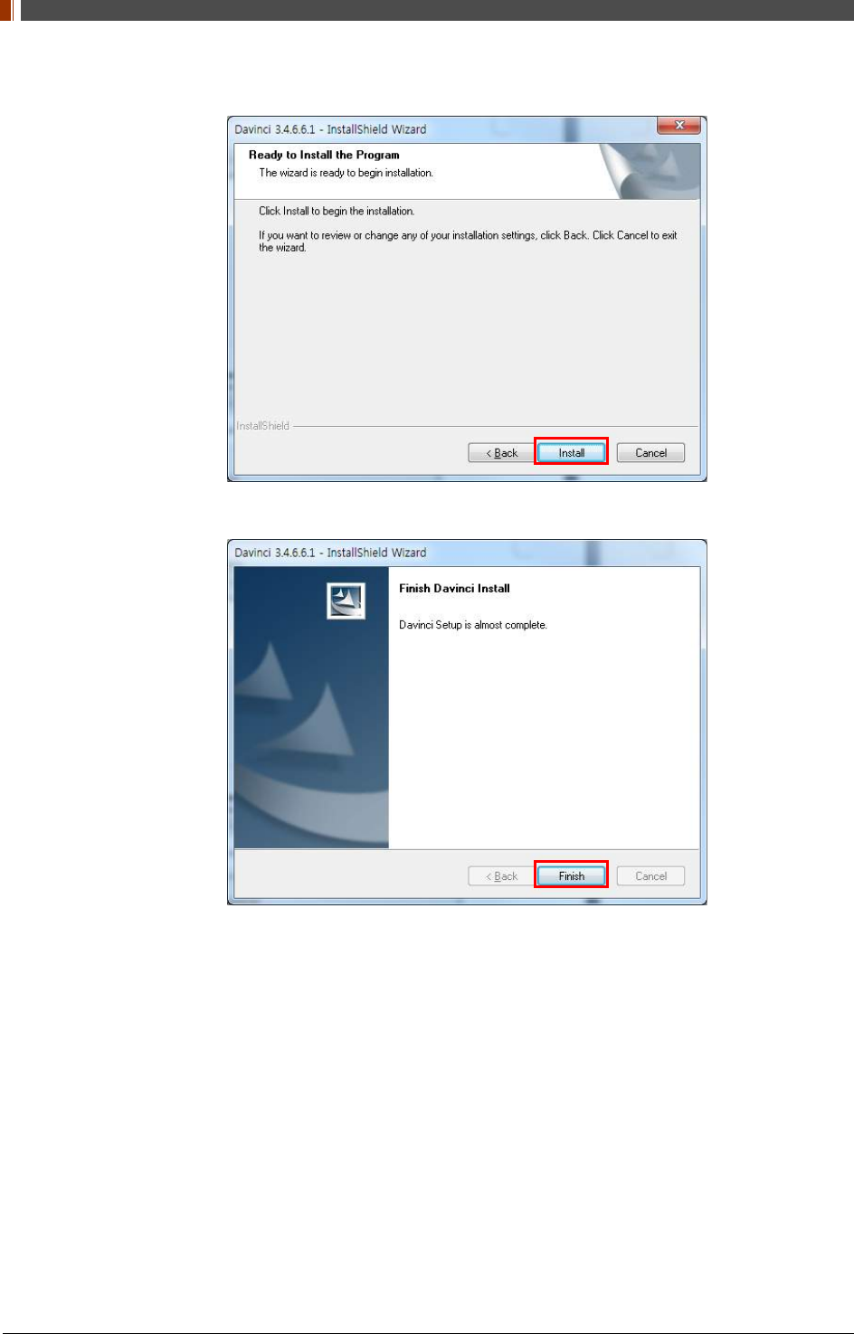
6. Click “Install”.
7. Click “Finish”.
PART II. Service Manual
1417WGC/WCC 45
3.1.2 Install battery
Attach the battery (RB37WHA) to the detector as below.
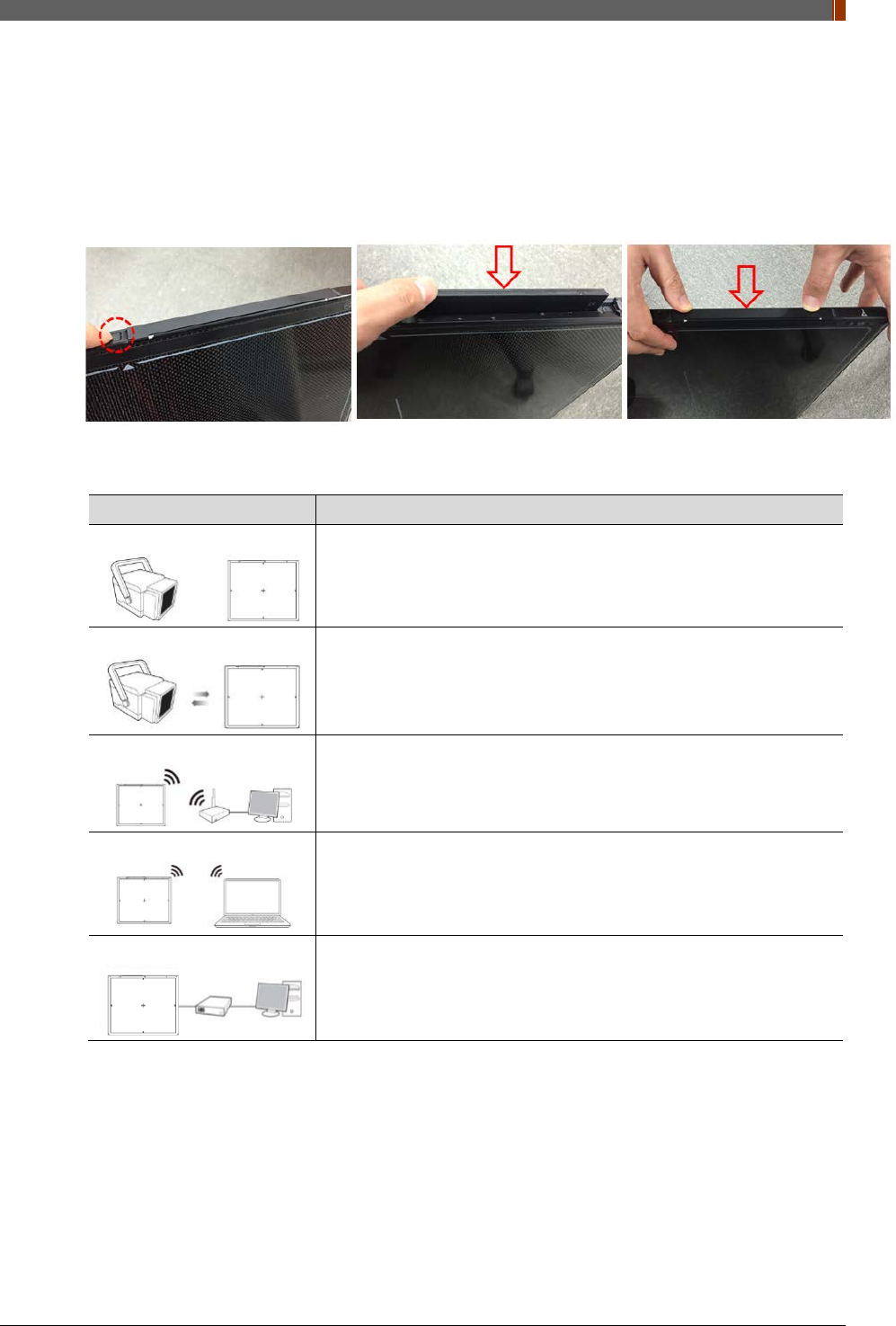
• Battery removal
Push the battery unlock button.
3.1.3 Mode Selection
Mode Description
<Auto Trigger>
Automatically detects X-ray radiation without integration of the
generator and detector.
<Manual Trigger>
Detects X-ray radiation by sending and receiving sync signals through
the integration between generator and detector.
<Station Mode>
Communicates with the wireless AP, and the wireless AP
communicates with the PC through the LAN cable.
(Rayence does not provide wireless AP.)
<AP Mode>
Detector communicates with the PC without the wireless AP.
(PC must maintain wireless network card.)
<Wired Mode>
Communicates with the power supply, and the power supply
communicates with the PC through the LAN cable.

PART II. Service Manual
1417WGC/WCC 51
3.1.4 Product Set Up
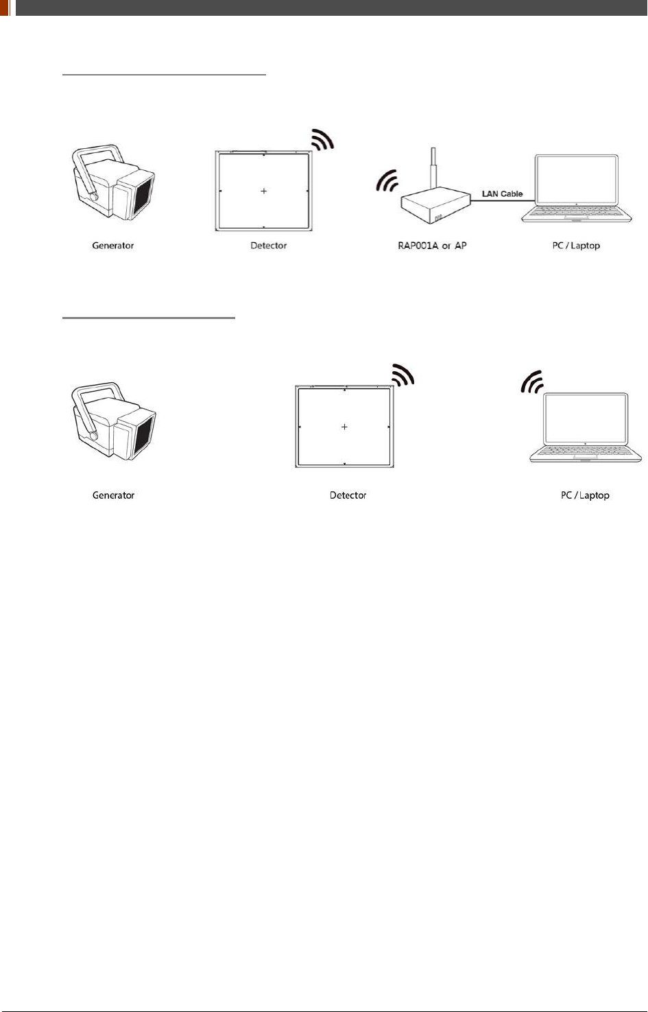
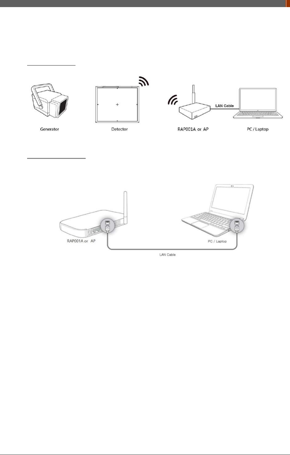
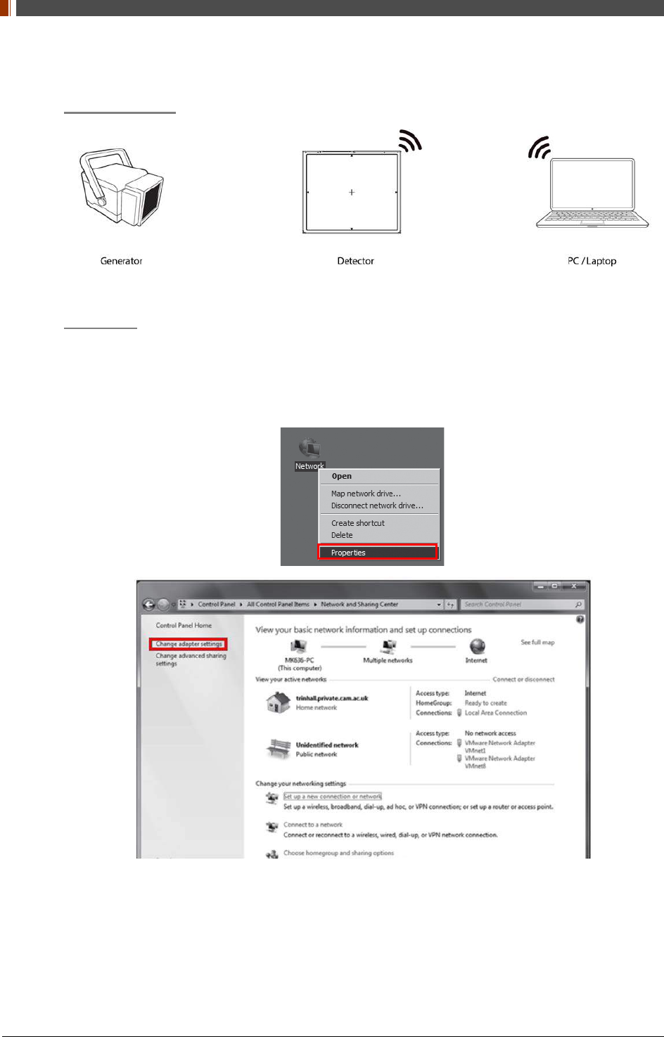
1. Auto Trigger & Station Mode
Product Set up
Connect the cable
1. Connect the wireless AP (or RAP001A) and PC with the LAN cable.
PART II. Service Manual
1417WGC/WCC 52
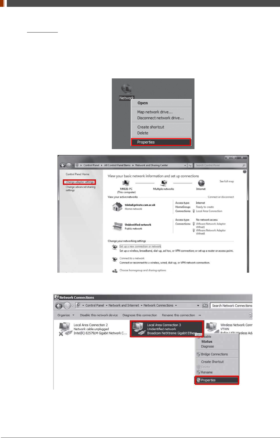
PC Set up
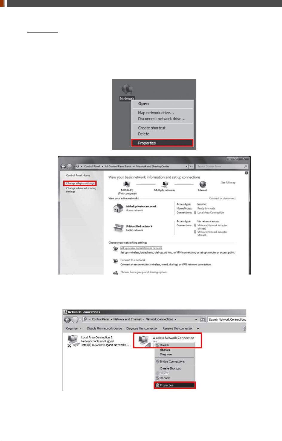
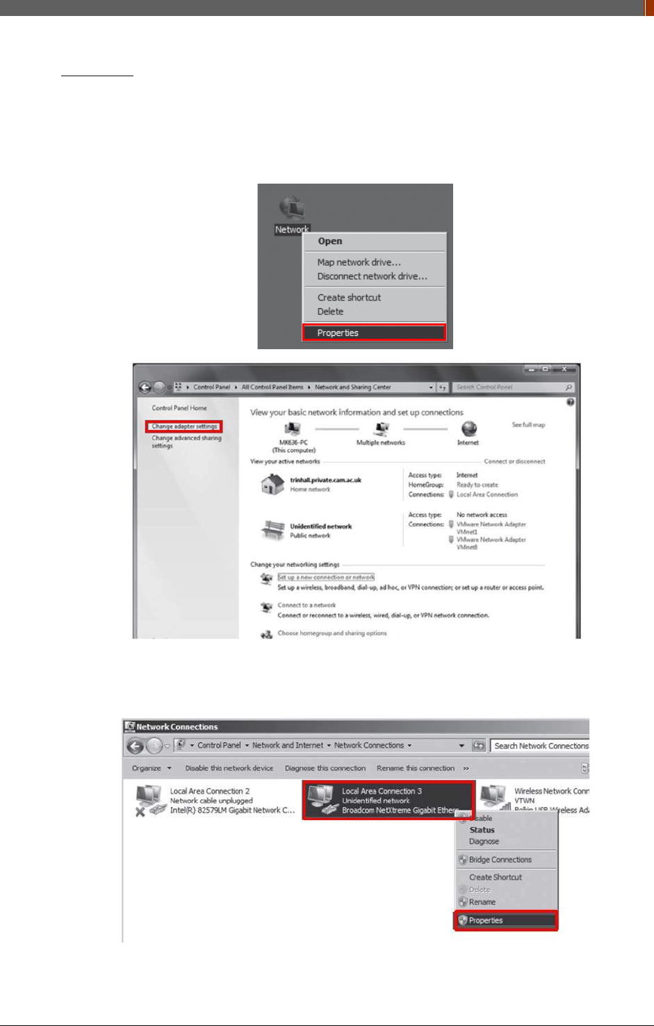
1. Set up the Network as below.
• Desktop > Network Icon > Right click > Properties > Change Adaptor Settings
• Control Panel > Network and Sharing Center > Change Adaptor Settings
2. To use station mode, right click "Local Area Connection" and click Properties.
PART II. Service Manual
1417WGC/WCC 53
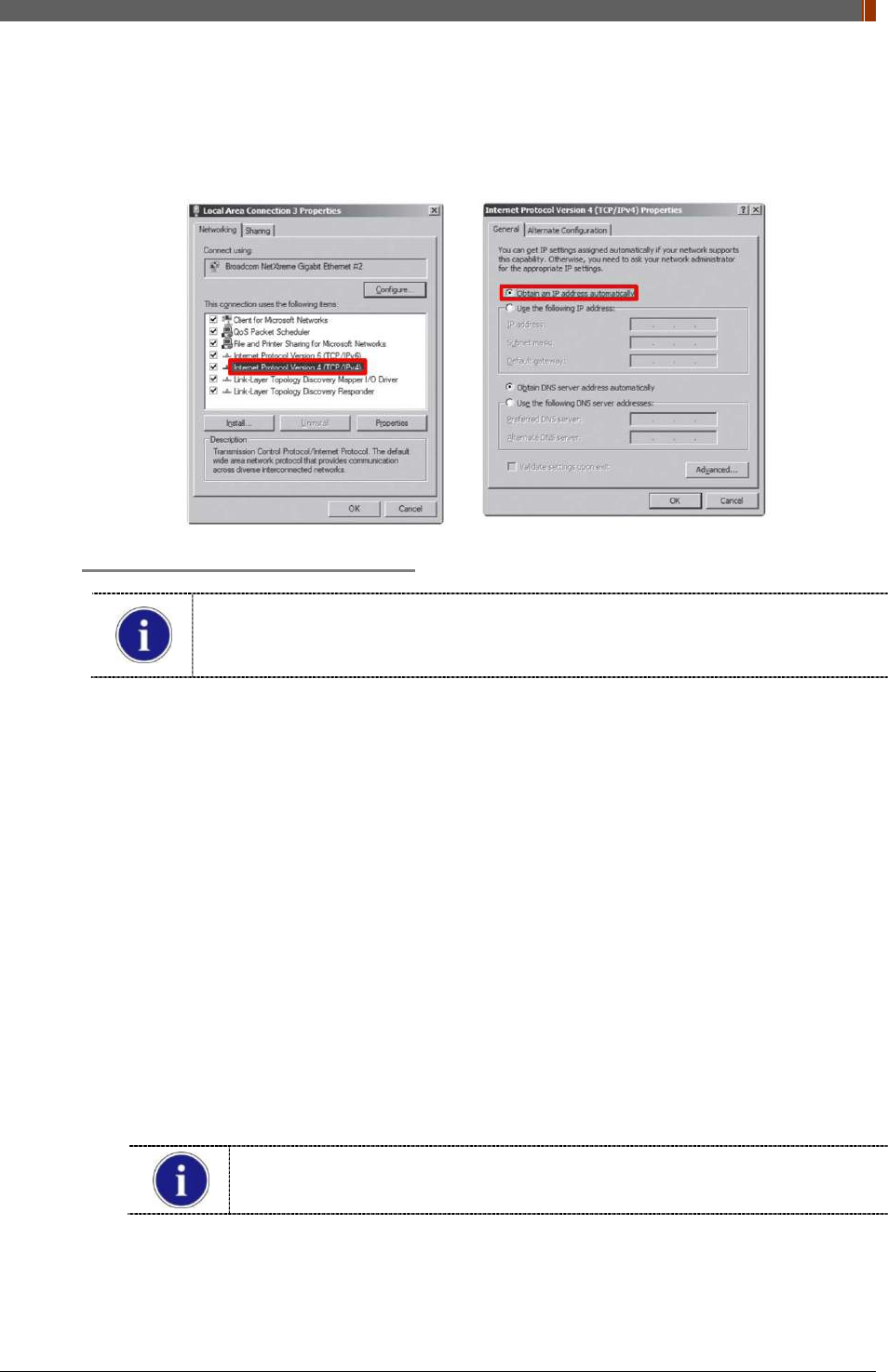
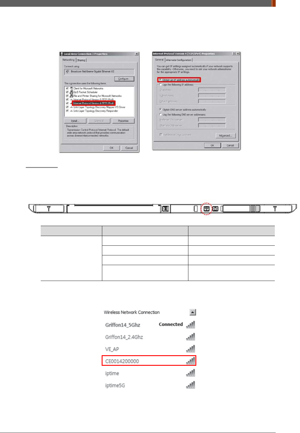
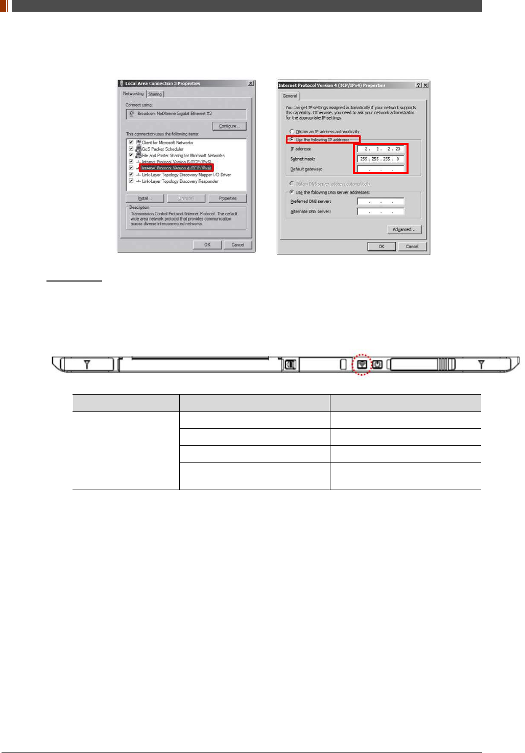
3. Double click “Internet Protocol Version 4 (TCP/IPv4)”.
4. Select “Obtain an IP address automatically” and click "OK".
Wireless AP (Access Point) Set up
Rayence does not provide wireless AP. Please use certified wireless AP and follow
each manufacture's setup manual.
(Recommended Model: Minimum ASUS RT-AC66U or RAP001A)
1. Set up wireless AP as below.
• SSID: Griffon
• Internal network
• IP address: 2.2.2.1
• Subnet mask: 255.255.255.0
• Dynamic IP allocation range: 2.2.2.2 ~ 2.2.2.254
• Pre-Shared Key(PSK): project302
• Authentication methods: WPAPSK or WPA2PSK
• Password methods: TKIP/AES
• Channel (Frequency)
Avoid the crowded channel option.
Recommend to use "Auto-Channel selection" function if external AP has the
feature.
Part.2 Service Manual Supplement 1. Refer to Wireless AP Set Up Instruction
(WAP Model: ASUS RT-AC66U).
PART II. Service Manual
1417WGC/WCC 54
Set up SW
1. Connect Detector and turn on the power.
2. Choose Station Mode by pressing and holding the Mode Button.
LED LED Color Mode
MODE
Orange Station Mode(Wireless)
Green AP Mode(Wireless)
None Wired Mode
Blinking Orange and Green
alternatively Sleep Mode
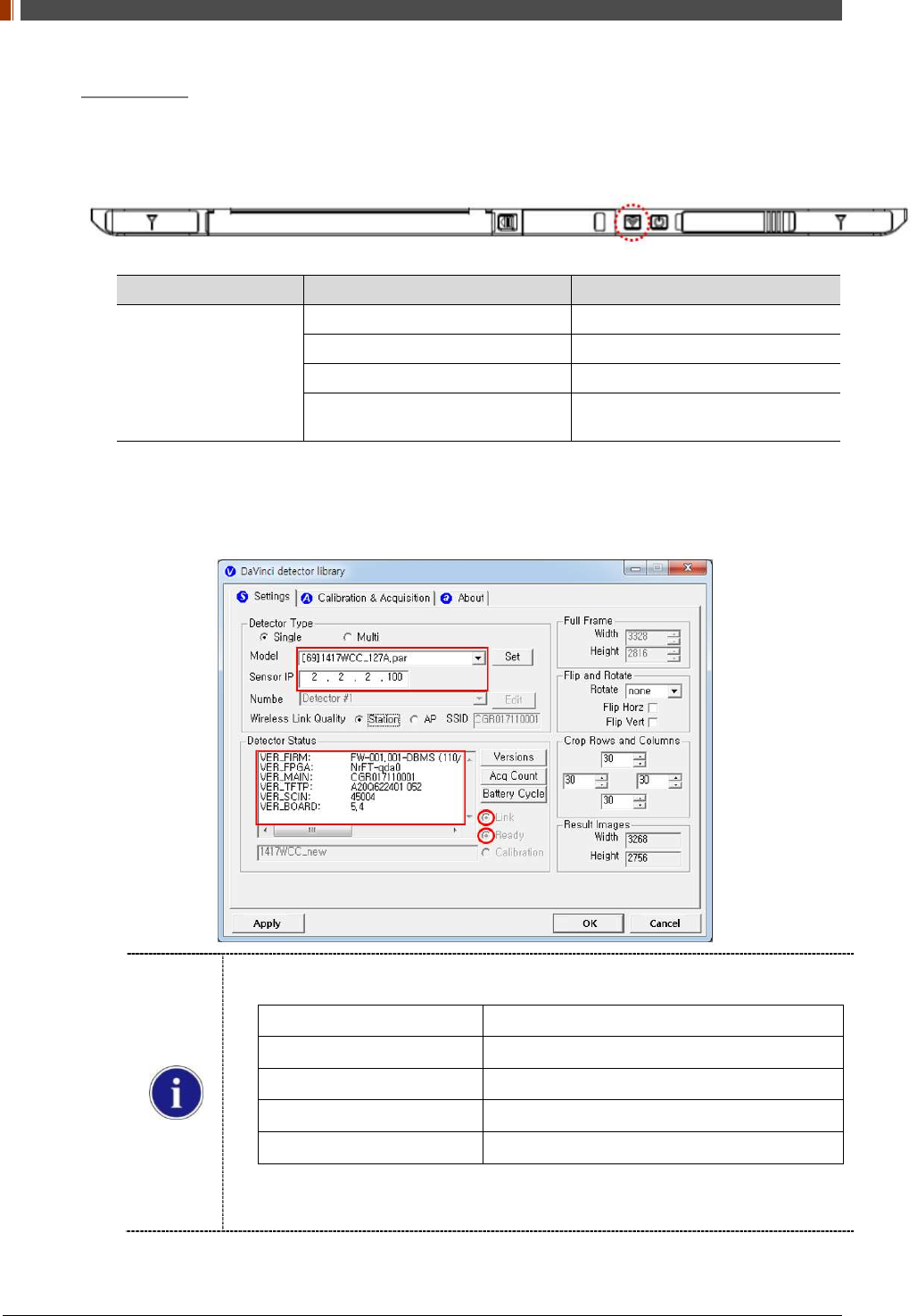
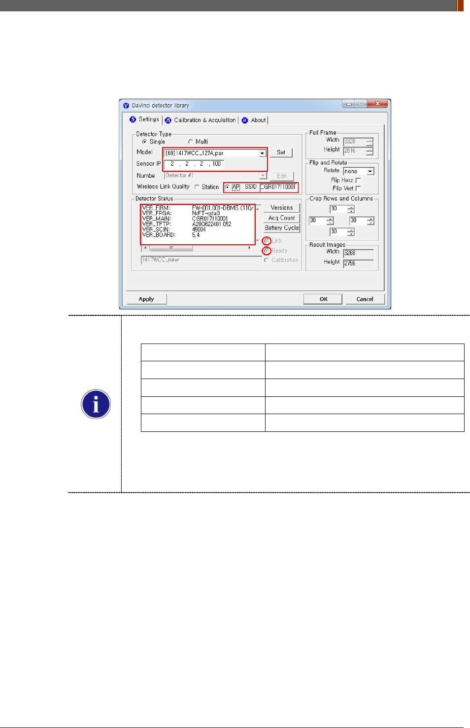
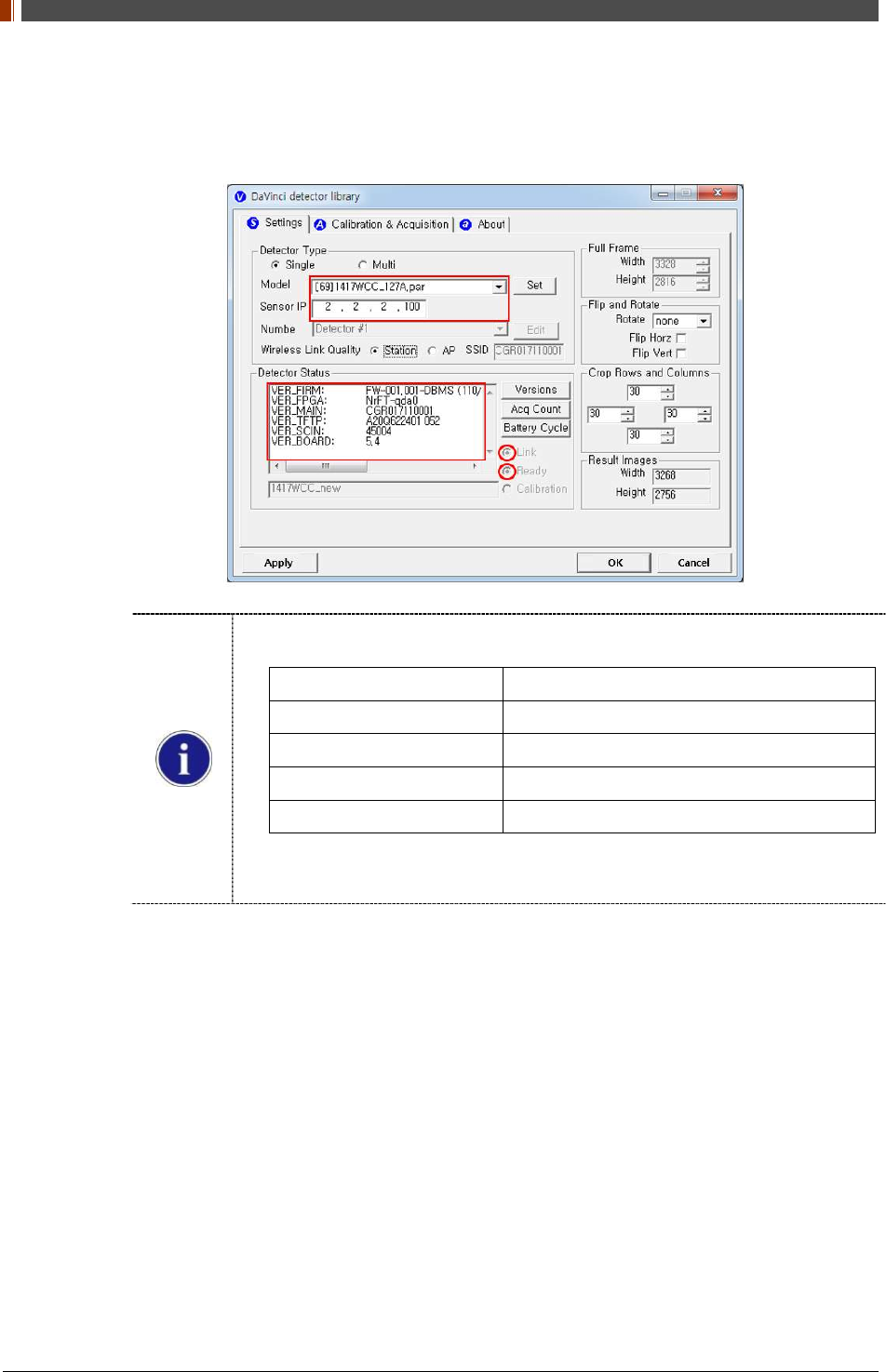
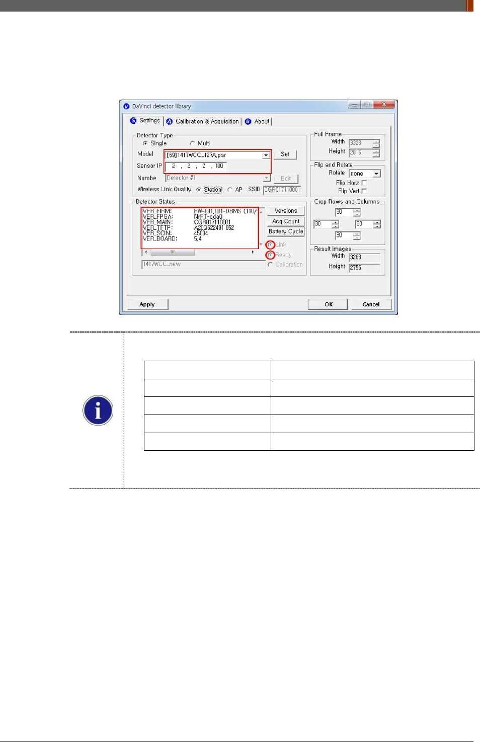
3. Open “_vadav.lnk” from “C:\davinci”.
Once the program is opened and the detector is connected, the LINK LED light from the
detector will blink and the Detector Status will display information of the detector as below.
Once the correct Sensor IP is put into the Davinci, it will automatically pull the
parameter of the connected detector.
Model type Parameter Selected
1417WCC _127A [69]1417WCC_127A.par
1417WCC _140A [71]1417WCC_140A.par
1417WGC _127A [70]1417WGC_127A.par
1417WGC _140A [72]1417WGC_140A.par
Default IP address for wireless connection is 2.2.2.100 and for wired connection is
2.2.2.101. If the IP address needs to be changed, please refer to 2.1 Detector IP
Address Set Up in Part.2 Service Manual.
PART II. Service Manual
1417WGC/WCC 55
If the detector does not communicate with the PC, please check the connection of the
cable, PC set up and power of the detector.
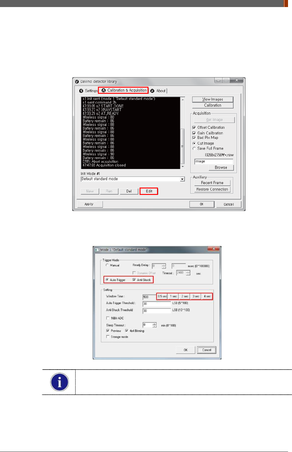
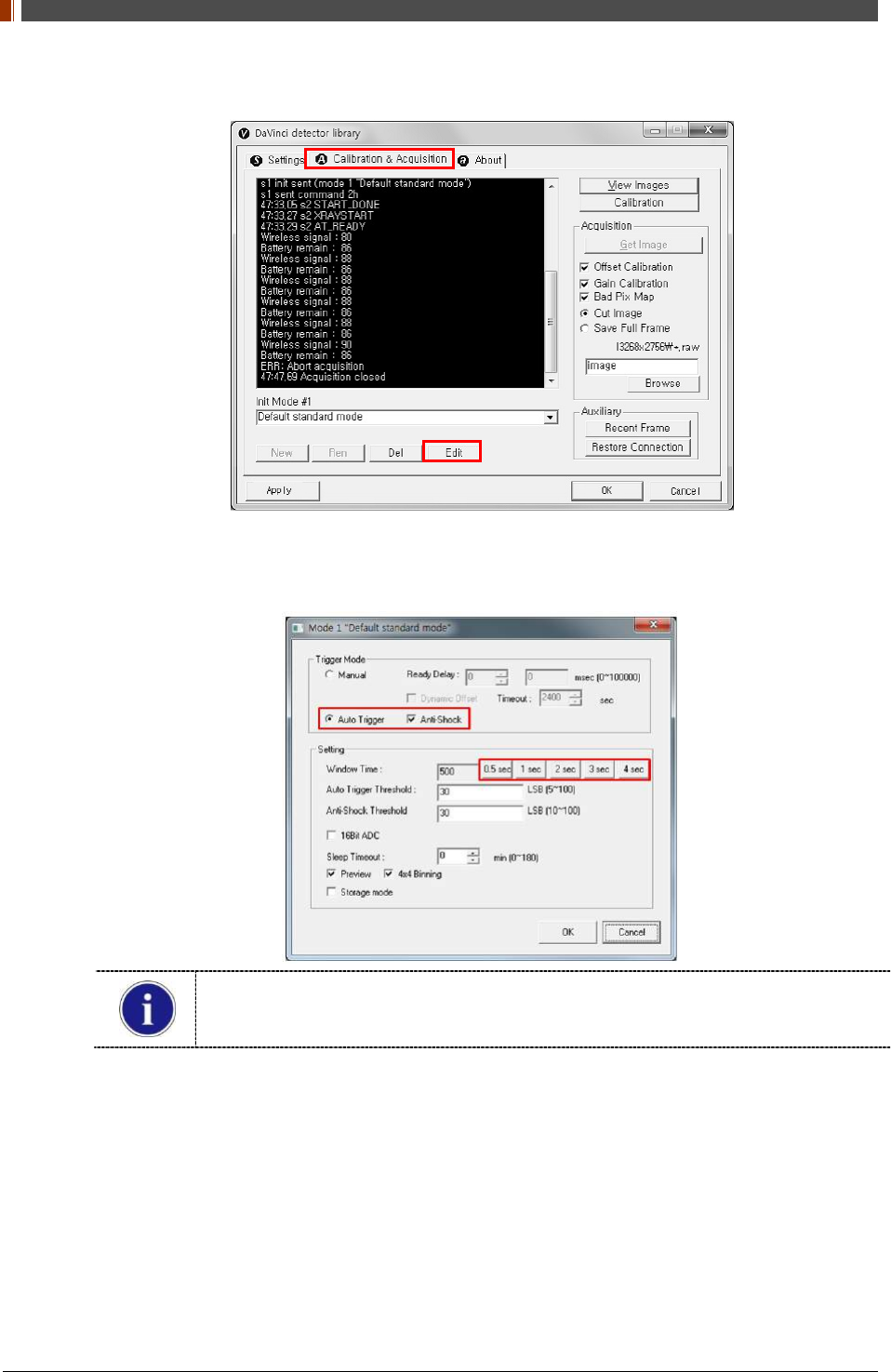
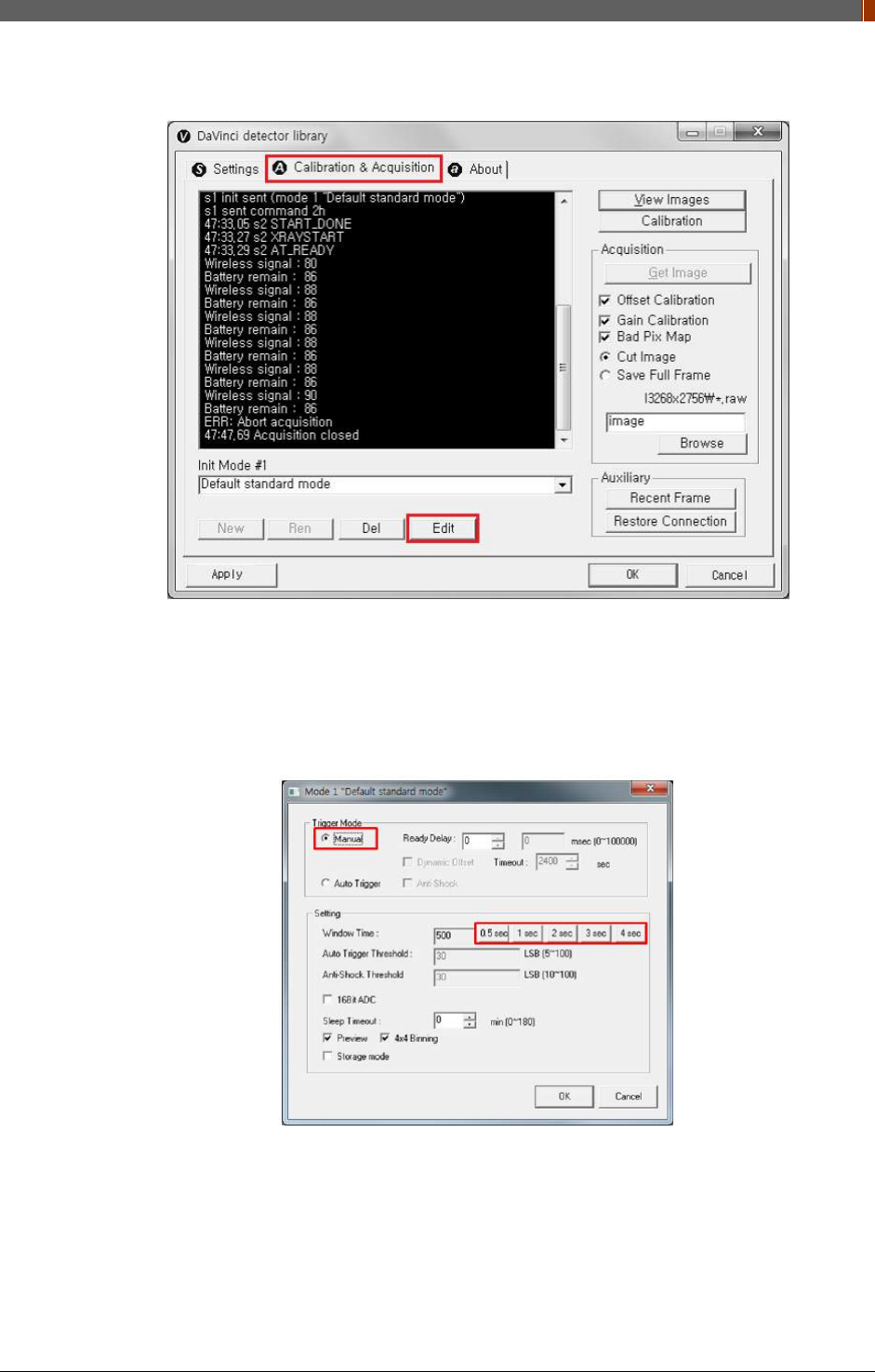
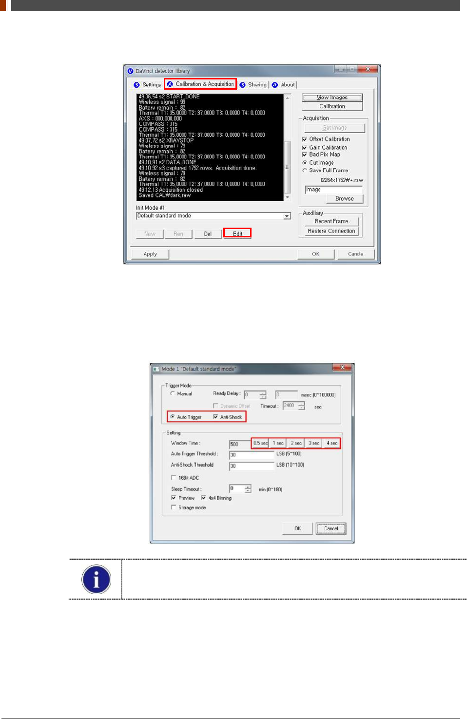
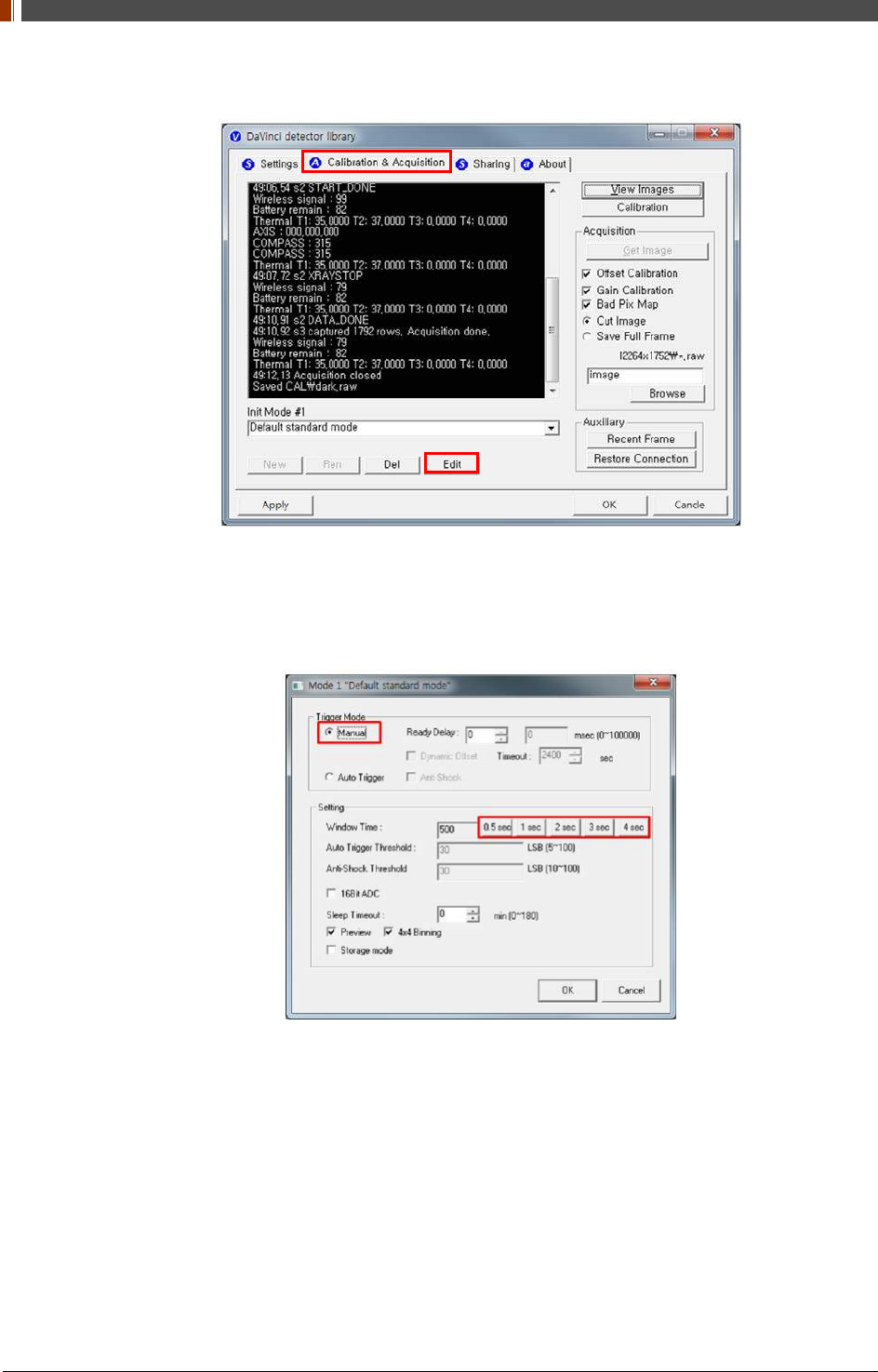
4. After checking connectivity, click the “Calibration & Acquisition” tab and click "Edit".
5. Another window will now be opened as shown below. Select "Auto Trigger" from "Trigger
Mode". If the "Window time" needs to be changed, type the value at "Window Time" from
"Setting".
In Auto trigger mode, be sure to set the "Window time" longer than an exposure
time. If the "Window time" is shorter than the exposure time, images will not be
properly acquired.
PART II. Service Manual
1417WGC/WCC 56
2. Auto Trigger & AP Mode
Product Set Up
PC Set up
1. Set up the Network as below.
• Desktop > Network Icon > Right click > Properties > Change Adaptor Settings
• Control Panel > Network and Sharing Center > Change Adaptor Settings
PART II. Service Manual
1417WGC/WCC 57
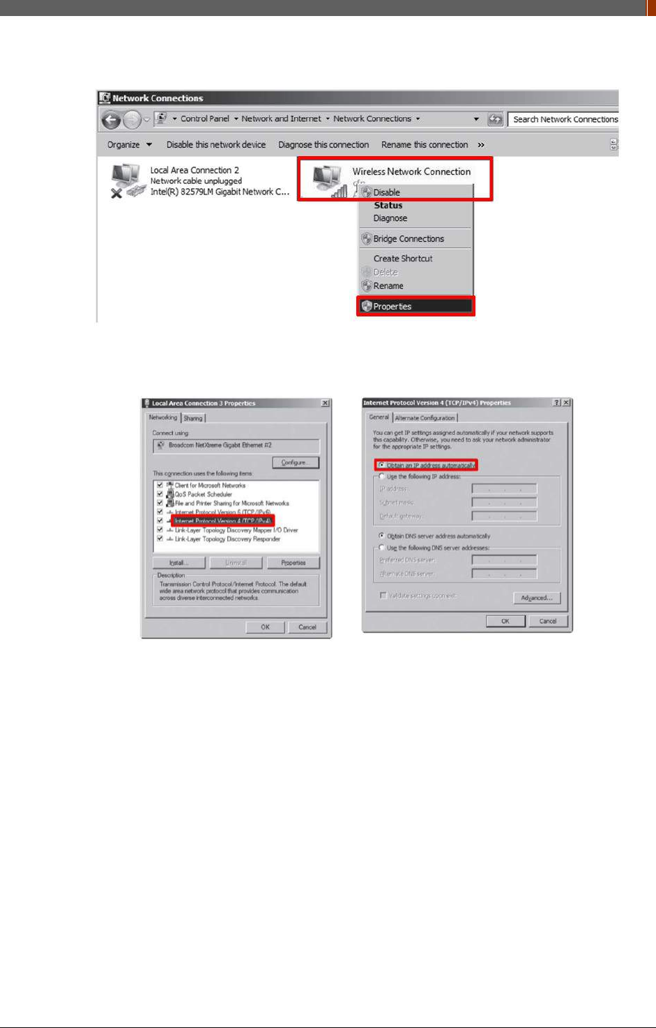
2. To use AP mode, right click "Wireless Network Connection" and click Properties.
3. Double click “Internet Protocol Version 4 (TCP/IPv4)”.
4. Select “Obtain an IP address automatically” and click "OK".
PART II. Service Manual
1417WGC/WCC 58
Set up SW
1. Connect the Detector and turn on the power.
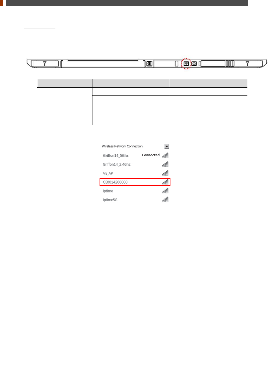
2. Choose AP Mode by pressing and holding the Mode button
LED LED Color Mode
MODE
Orange Station Mode(Wireless)
Green AP Mode(Wireless)
None Wired Mode
Blinking Orange and Green
alternatively Sleep Mode
3. Choose the SSID (detector's SN) from Wireless Network Connection list. (PW: project302)
PART II. Service Manual
1417WGC/WCC 59
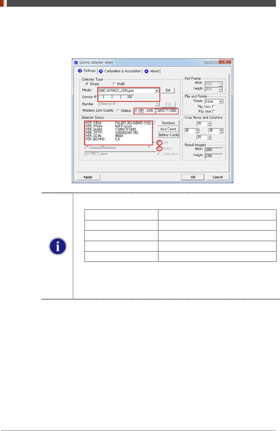
4. Open “_vadav.lnk” from “C:\davinci”.
Once the program is opened and the detector is connected, the LINK LED light will blink
and the Detector Status will display detector information as below.
Once the correct Sensor IP is put into the Davinci, it will automatically pull the
parameter of the connected detector.
Model type Parameter Selected
1417WCC _127A [69]1417WCC_127A.par
1417WCC _140A [71]1417WCC_140A.par
1417WGC _127A [70]1417WGC_127A.par
1417WGC _140A [72]1417WGC_140A.par
Default IP address for wireless connection is 2.2.2.100 and for wired connection is
2.2.2.101. If the IP address needs to be changed, please refer to 2.1 Detector IP
Address Set Up in Part.2 Service Manual.
In the AP mode, select "AP" from "Wireless Link Quality" and type the detector's
serial number at the "SSID".
If the detector does not communicate with the PC, please check the connection of the
cable, PC set up and power of the detector.
PART II. Service Manual
1417WGC/WCC 60
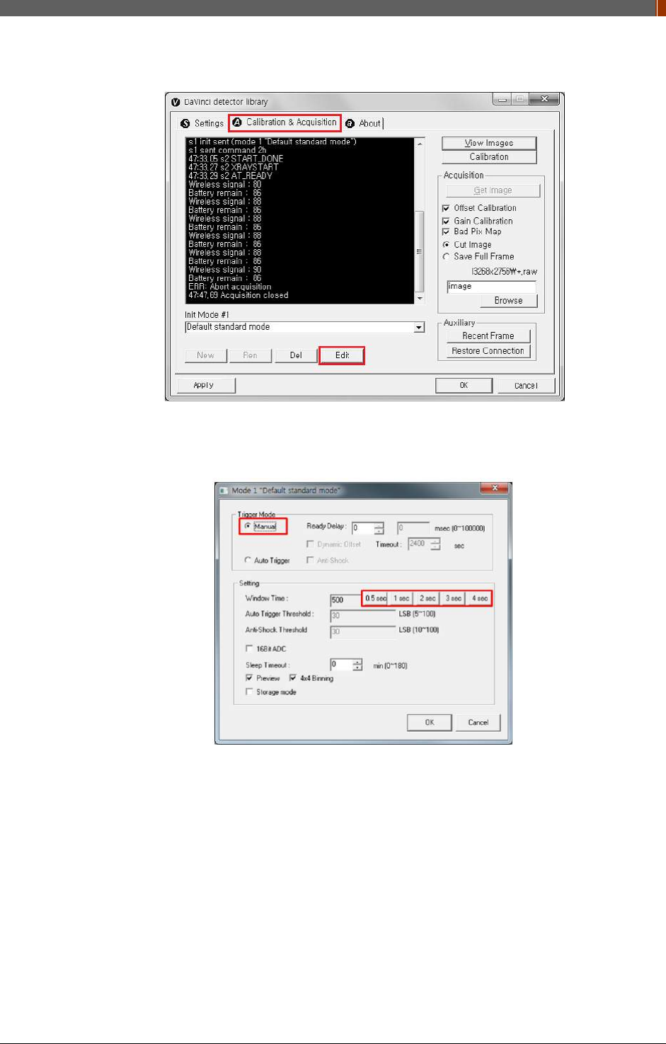
5. After checking connection, click the “Calibration & Acquisition” tab and click "Edit".
6. Another window will open as below once the “Edit” button is pressed. Select "Auto Trigger"
from "Trigger Mode". If "Window time" needs to be changed, type the value at "Window
Time" from "Setting".
In Auto trigger mode, be sure to set the "Window time" longer than an exposure time. If
the "Window time" is shorter than the exposure time, images will not be properly
acquired.
PART II. Service Manual
1417WGC/WCC 61
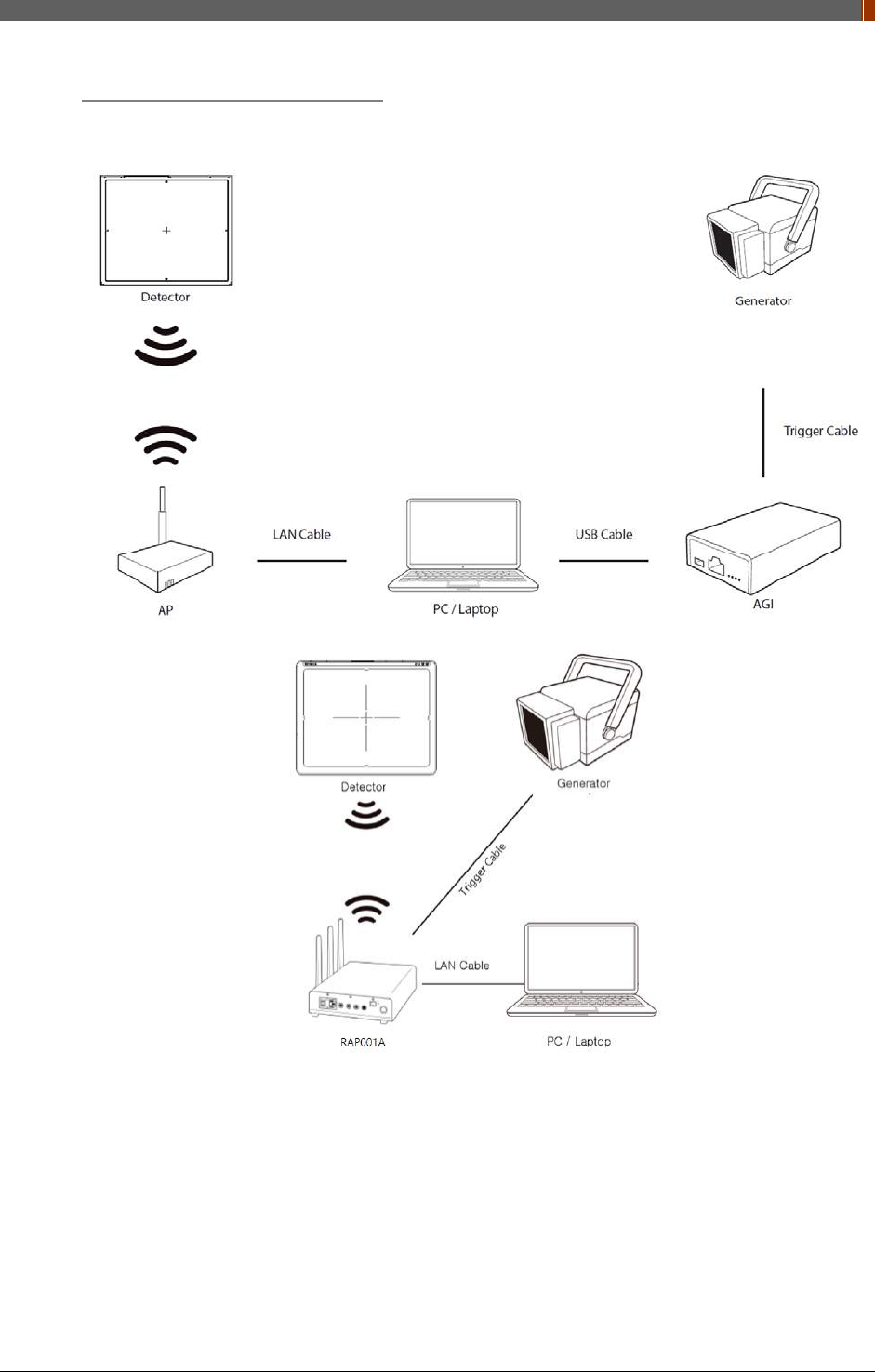
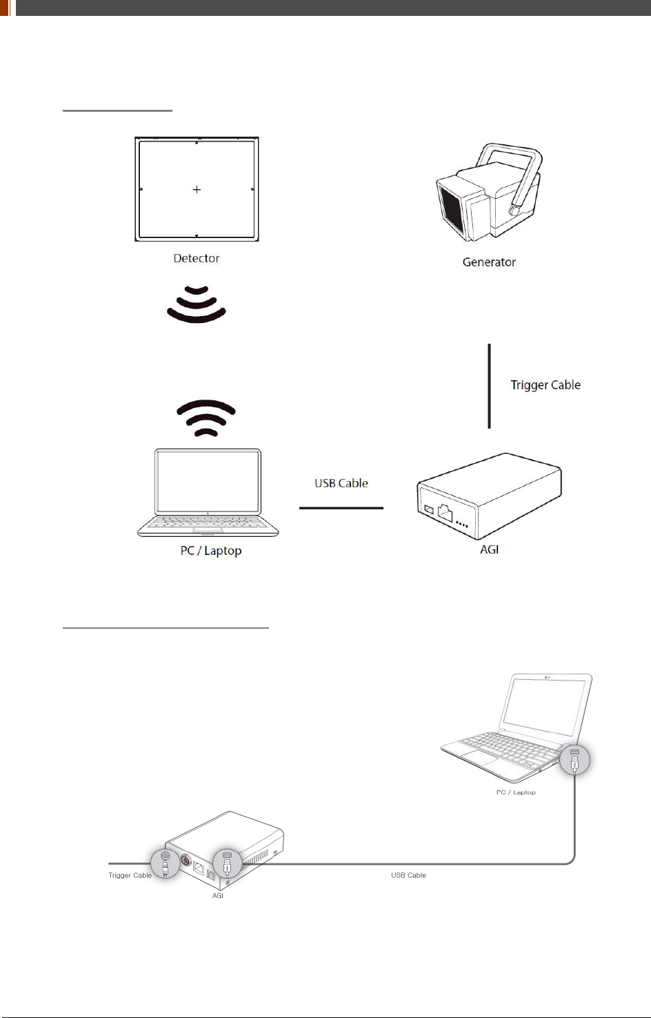
3. Manual Trigger & Station Mode
Product Set up
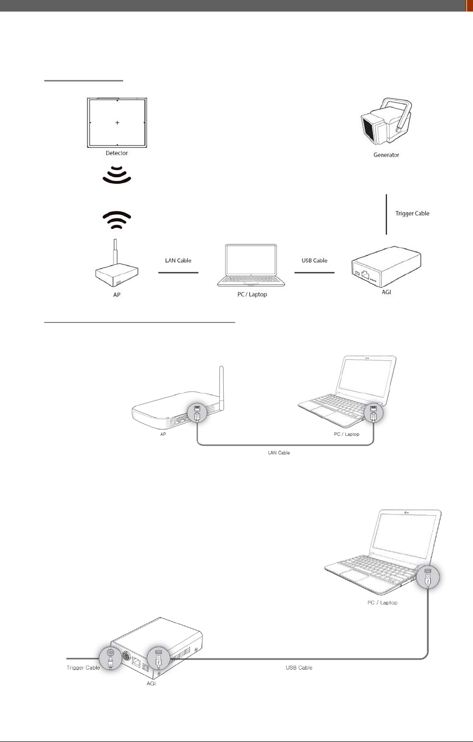
Connect the cable (with AGI and AP)
1. Connect the wireless AP and PC with the LAN cable.
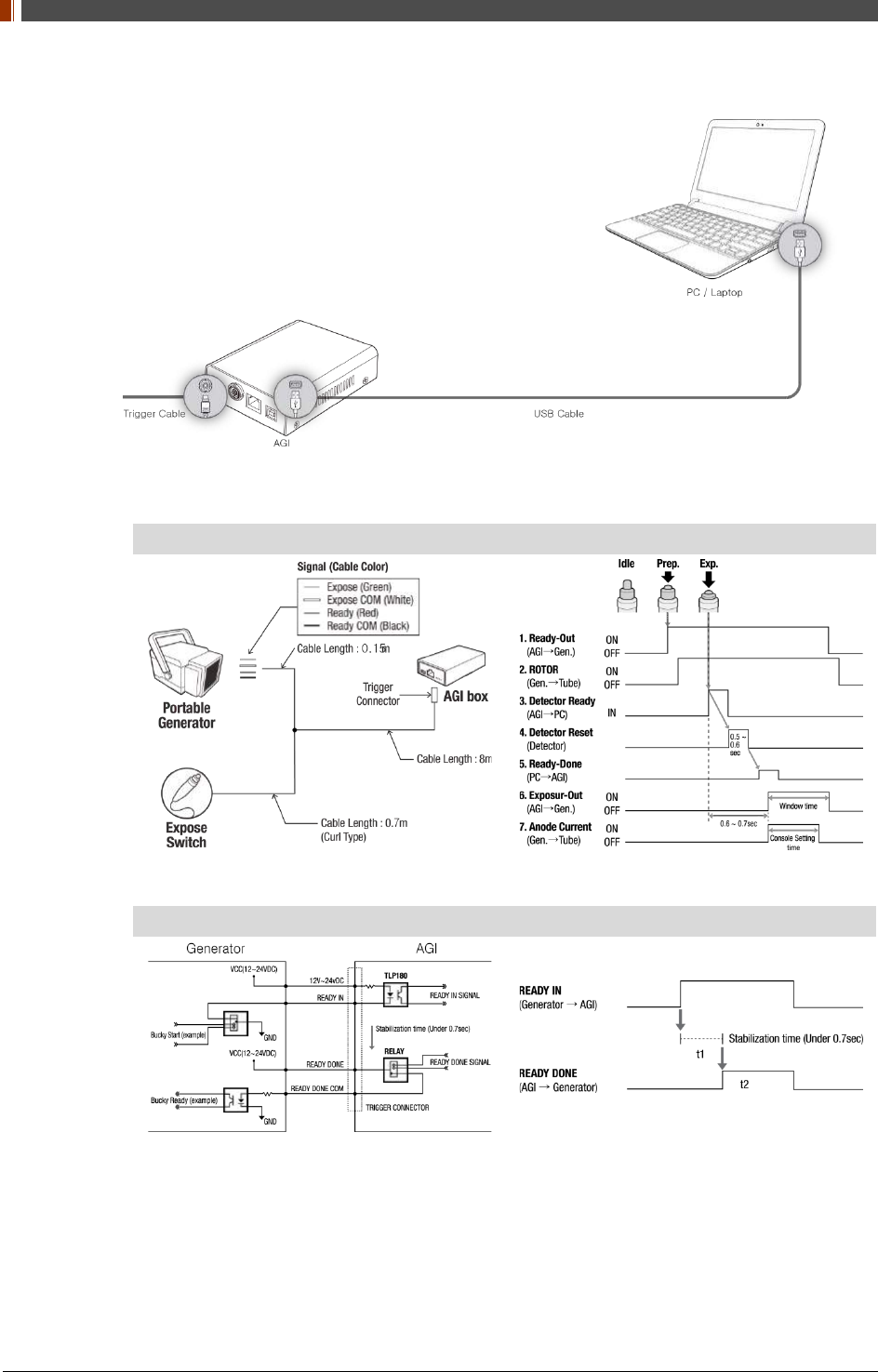
2. Connect the AGI box and PC with the USB cable.
PART II. Service Manual
1417WGC/WCC 62
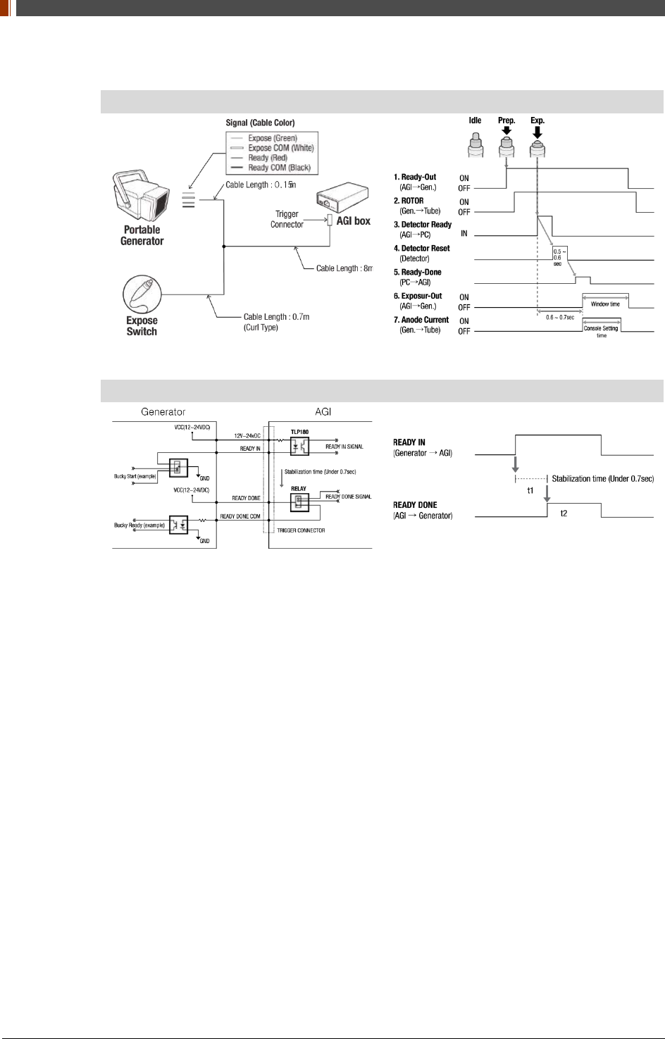
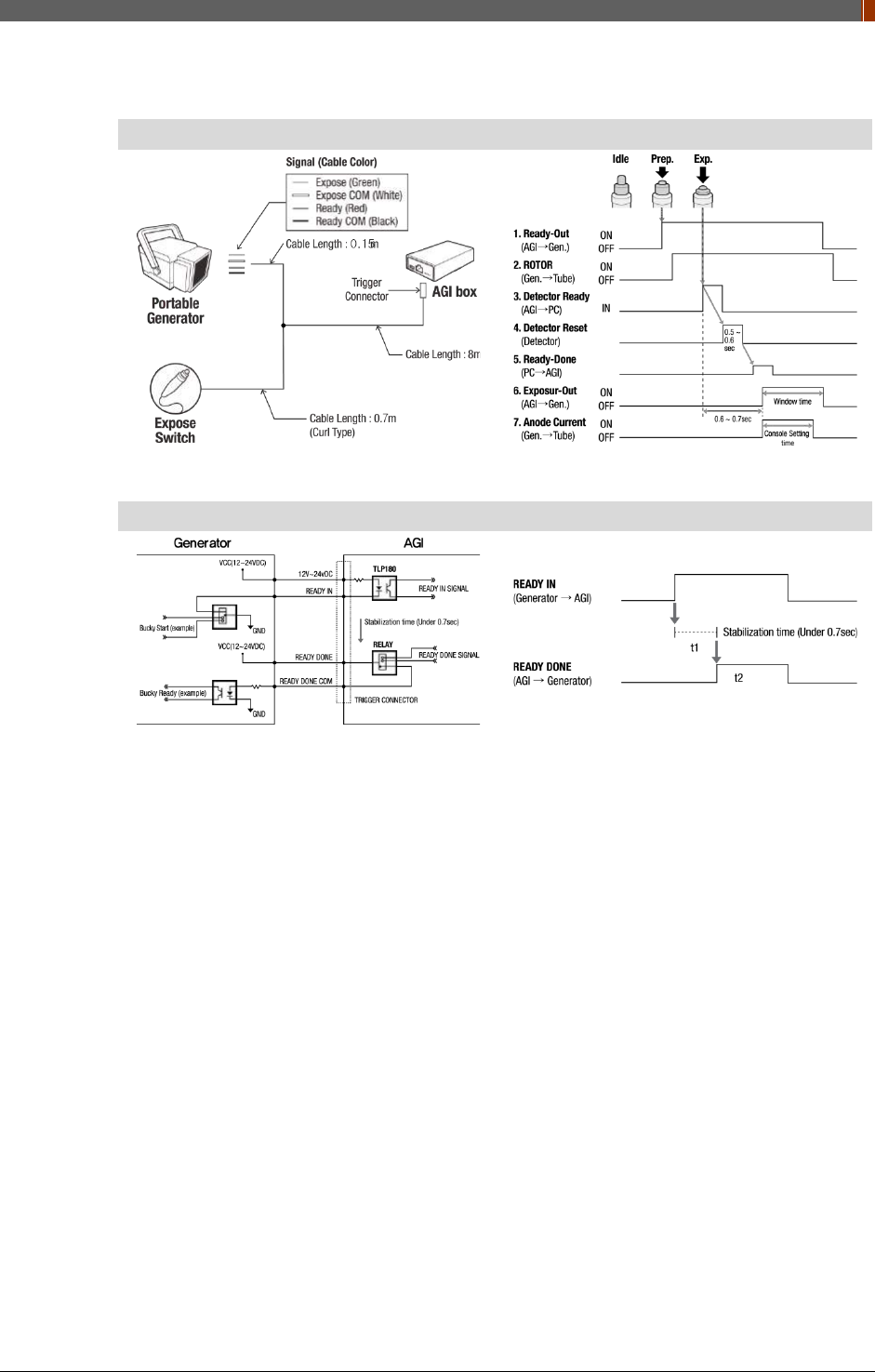
3. Connect the AGI box and generator with the P-interface or trigger cable.
Instruction of P-interface cable Integration
<Assembly Diagram> <Timing Chart>
Instruction of Trigger cable Integration
<Assembly Diagram> <Timing Chart>
PART II. Service Manual
1417WGC/WCC 63
Product Set up (with RAP001A)
Connect the cable (with RAP001A)
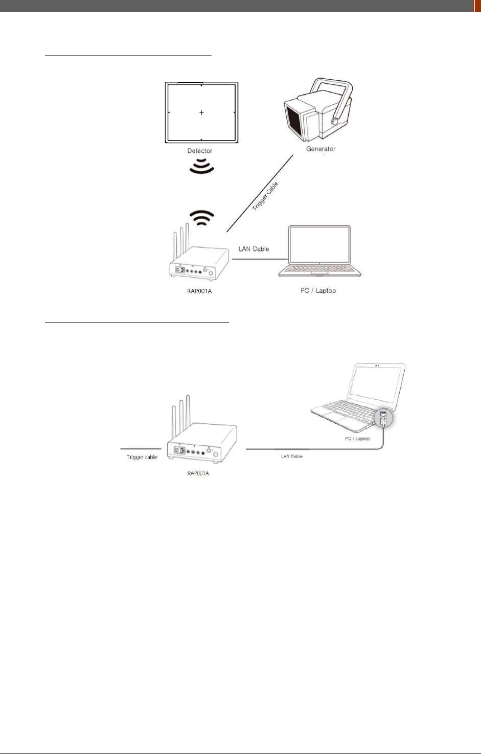
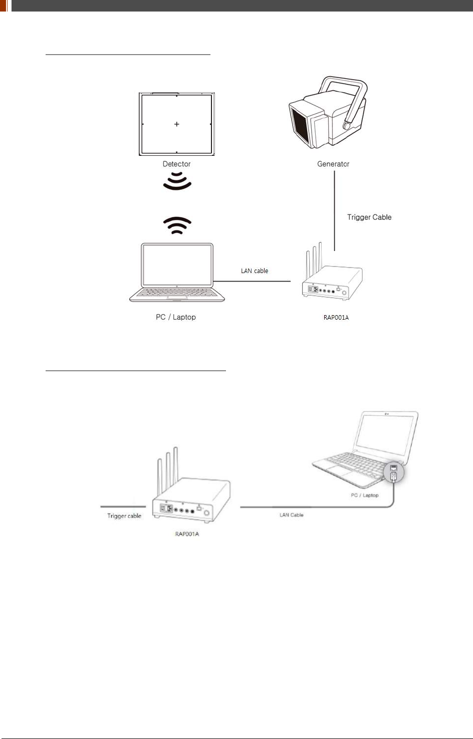
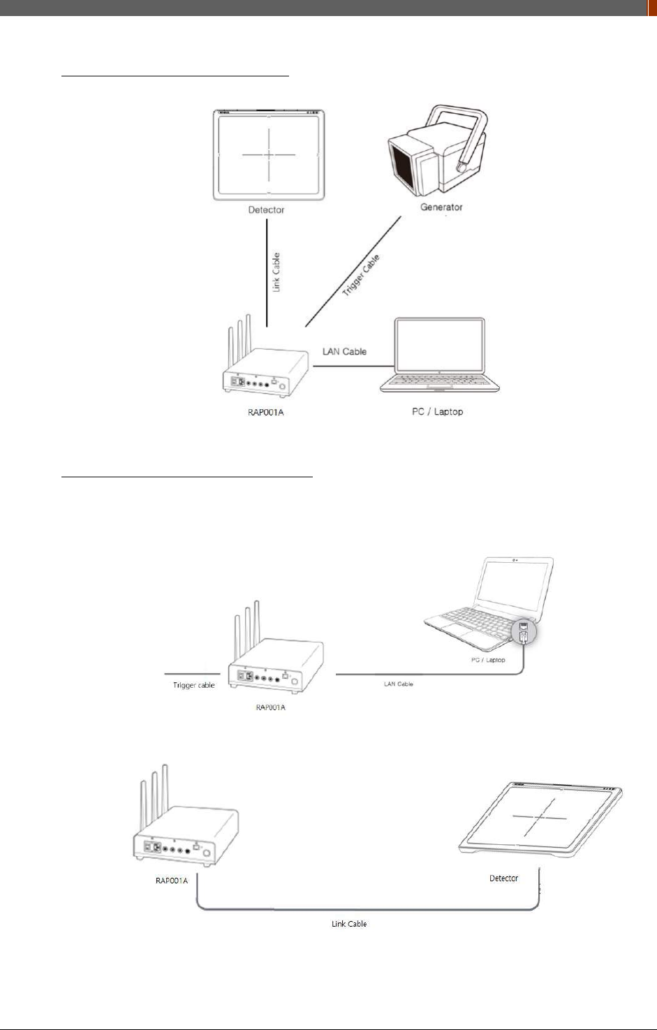
1. Connect the RAP001A and PC with the LAN cable.
PART II. Service Manual
1417WGC/WCC 64
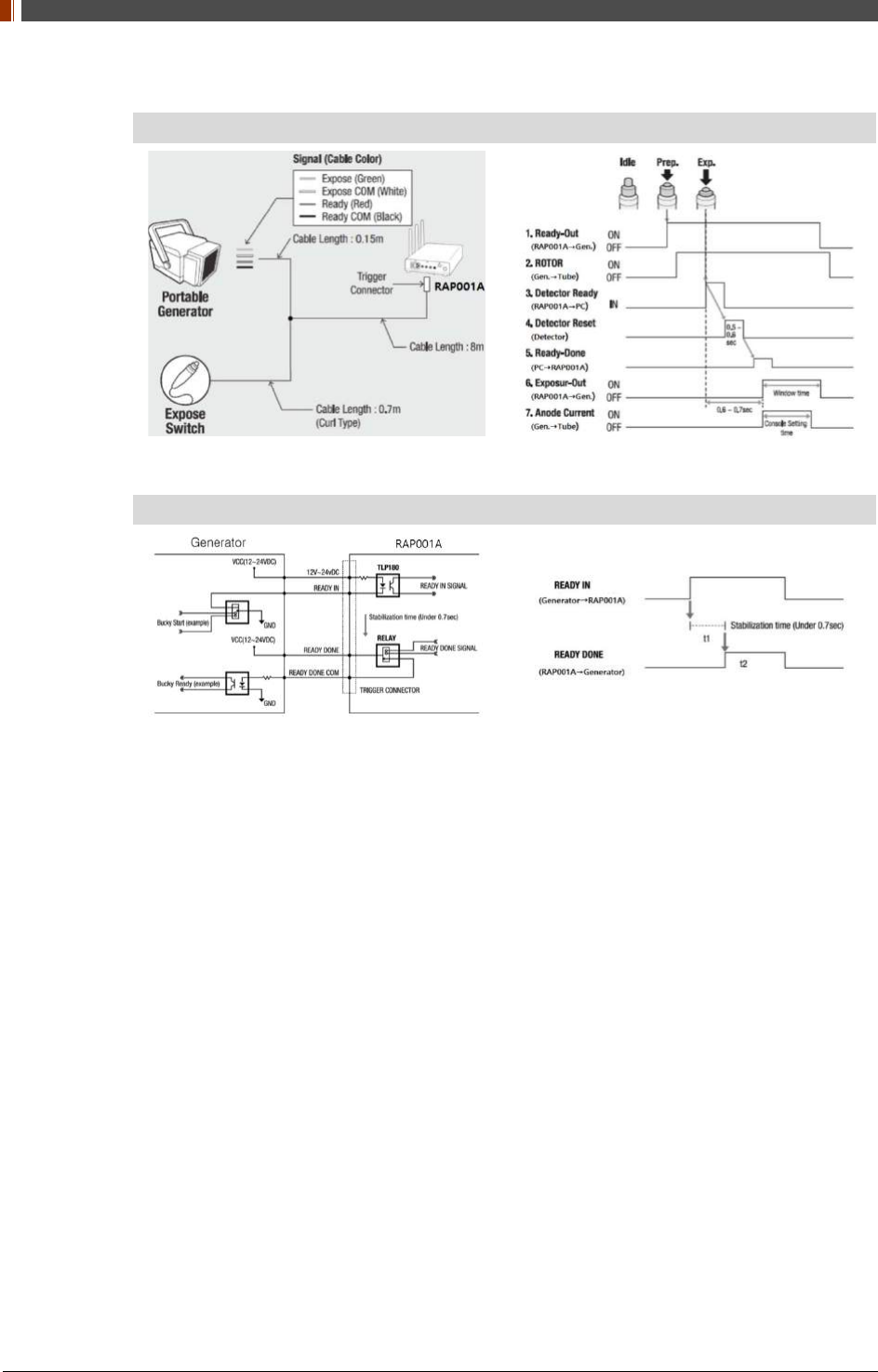
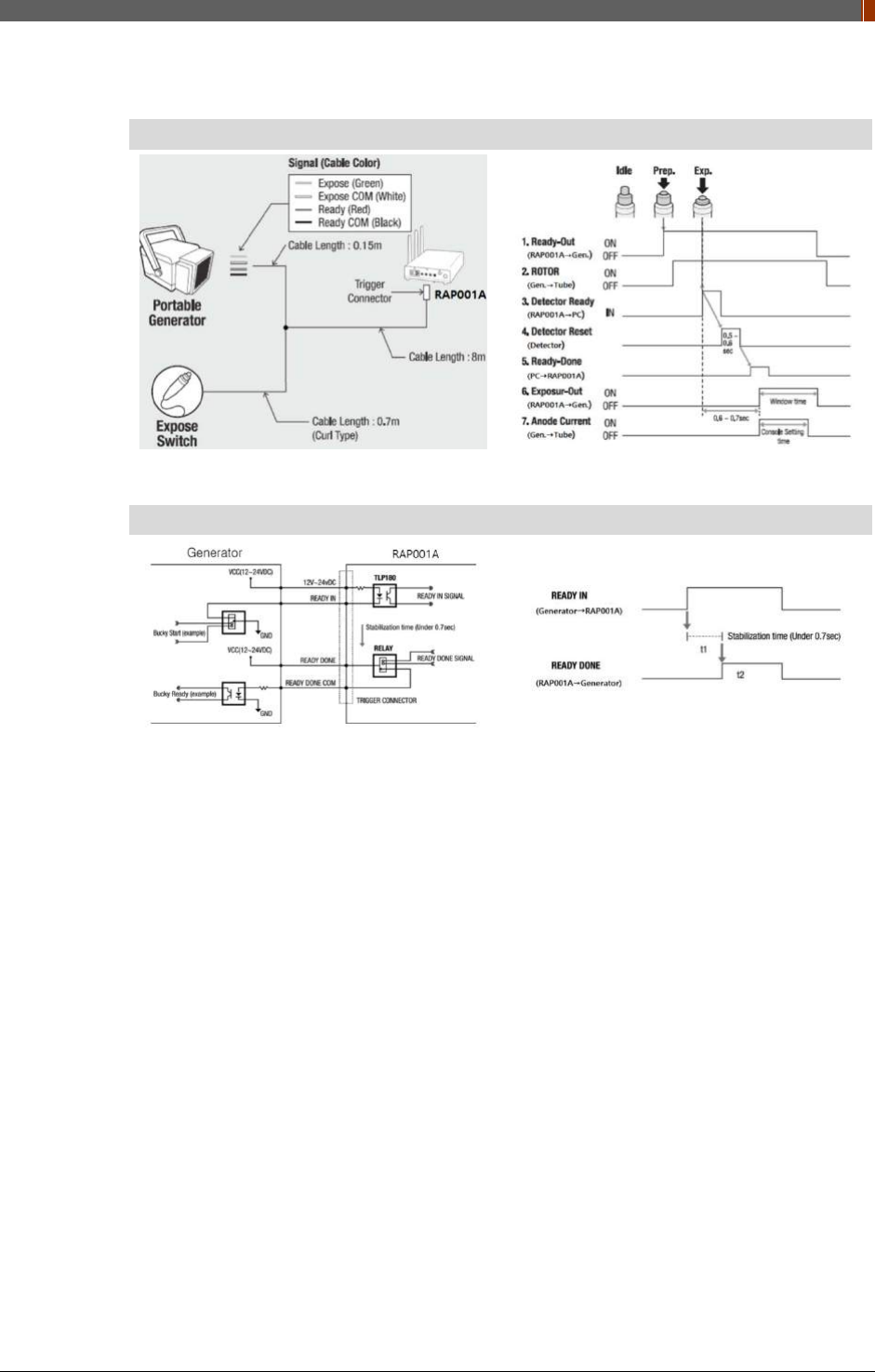
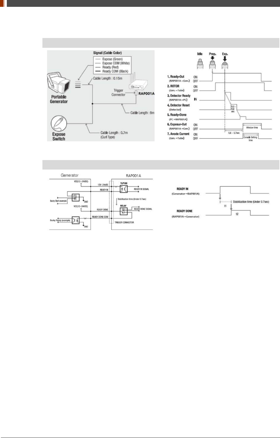
2. Connect the RAP001A and generator with the P-interface or trigger cable.
Instruction of P-interface cable Integration
<Assembly Diagram> <Timing Chart>
Instruction of Trigger cable Integration
<Assembly Diagram> <Timing Chart>
PART II. Service Manual
1417WGC/WCC 65
PC Set up
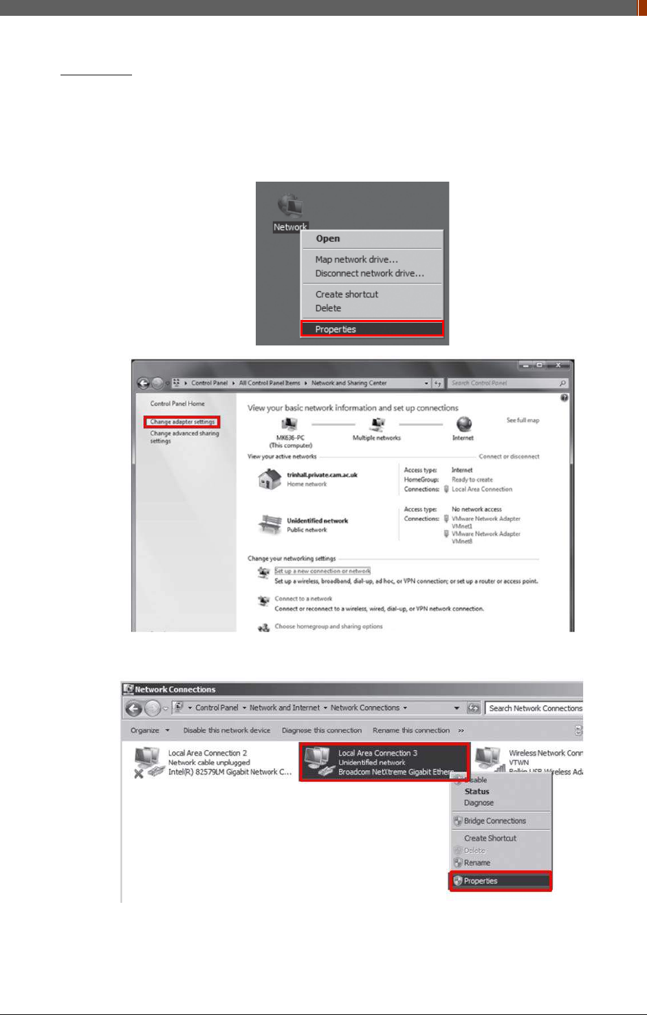
1. Set up the Network as below.
• Desktop > Network Icon > Right click > Properties > Change Adaptor Settings
• Control Panel > Network and Sharing Center > Change Adaptor Settings
2. To use station mode, right click "Local Area Connection" and click Properties.
PART II. Service Manual
1417WGC/WCC 66
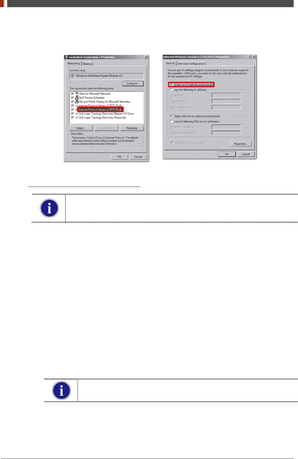
3. Double click “Internet Protocol Version 4 (TCP/IPv4)”.
4. Select “Obtain an IP address automatically” and click "OK".
Wireless AP (Access Point) Set up
Rayence does not provide wireless AP. Please use certified wireless AP and follow
each manufacture's setup manual.
(Recommended Model: Minimum ASUS RT-AC66U or RAP001A)
1. Set up wireless AP as below.
• SSID: Griffon
• Internal network
• IP address: 2.2.2.1
• Subnet mask: 255.255.255.0
• Dynamic IP allocation range: 2.2.2.2 ~ 2.2.2.254
• Pre-Shared Key(PSK): project302
• Authentication methods: WPAPSK or WPA2PSK
• Password methods: TKIP/AES
• Channel (Frequency)
Avoid the Crowded channel option.
Recommend to use "Auto-Channel selection" function if external AP has the
feature.
2. Part.2 Service Manual Supplement 1. Refer to Wireless AP Set Up Instruction (WAP
Model: ASUS RT-AC66U
PART II. Service Manual
1417WGC/WCC 67
Set up SW
1. Connect the Detector and turn on the power.
2. Choose Station Mode by pressing and holding the Mode Button
LED LED Color Mode
MODE
Orange Station Mode(Wireless)
Green AP Mode(Wireless)
None Wired Mode
Blinking Orange and Green
alternatively Sleep Mode
PART II. Service Manual
1417WGC/WCC 68
3. Open “_vadav.lnk” from “C:\davinci”.
Once the program is opened and the detector is connected, the LINK LED light will blink
and the Detector Status will display detector information as below.
Once the correct Sensor IP is put into the Davinci, it will automatically pull the
parameter of the connected detector.
Model type Parameter Selected
1417WCC _127A [69]1417WCC_127A.par
1417WCC _140A [71]1417WCC_140A.par
1417WGC _127A [70]1417WGC_127A.par
1417WGC _140A [72]1417WGC_140A.par
Default IP address for wireless connection is 2.2.2.100 and for wired connection
is 2.2.2.101. If the IP address needs to be changed, please refer to 2.1 Detector
IP Address Set Up in Part.2 Service Manual.
If the detector does not communicate with the PC, please check the connection of the
cable, PC set up and power of the detector.
PART II. Service Manual
1417WGC/WCC 69
4. After checking connectivity, click the “Calibration & Acquisition” tab and click "Edit".
5. Another window will be opened as below once the “Edit” button is pressed. Select "Manual"
from "Trigger Mode". If "Window time" needs to be changed, type the value at "Window
Time" from "Setting".
PART II. Service Manual
1417WGC/WCC 70
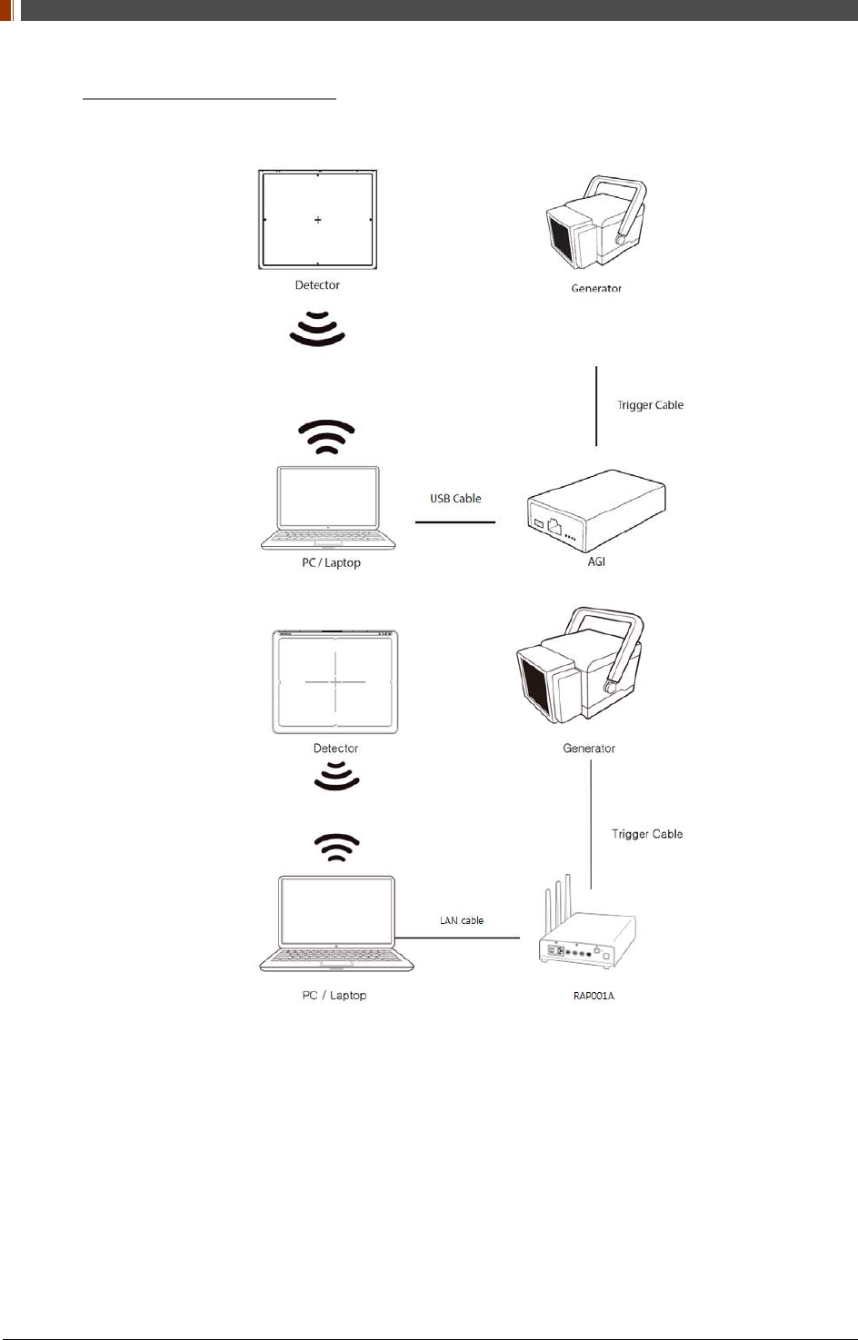
4. Manual Trigger & AP Mode
Product Set Up
Connect the cable (with AGI)
1. Connect the AGI box and PC with the USB cable.
PART II. Service Manual
1417WGC/WCC 71
2. Connect the AGI box and generator with a P-interface or trigger cable.
Instruction of P-interface cable Integration
<Assembly Diagram> <Timing Chart>
Instruction of Trigger cable Integration
<Assembly Diagram> <Timing Chart>
PART II. Service Manual
1417WGC/WCC 72
Product Set Up (with RAP001A)
Connect the cable (with RAP001A)
1. Connect the RAP001A and PC with the LAN cable.
PART II. Service Manual
1417WGC/WCC 73
2. Connect the RAP001A and generator with the P-interface or trigger cable.
Instruction of P-interface cable Integration
<Assembly Diagram> <Timing Chart>
Instruction of Trigger cable Integration
<Assembly Diagram> <Timing Chart>
PART II. Service Manual
1417WGC/WCC 74
PC Set up
1. Set up the Network as below.
• Desktop > Network Icon > Right click > Properties > Change Adaptor Settings
• Control Panel > Network and Sharing Center > Change Adaptor Settings
2. To use AP mode, right click "Wireless Network Connection" and click Properties.
PART II. Service Manual
1417WGC/WCC 75
3. Double click “Internet Protocol Version 4 (TCP/IPv4)”.
4. Select “Obtain an IP address automatically” and click "OK".
Set up SW
1. Connect the Detector and turn on the power.
2. Choose AP Mode by pressing and holding the Mode
LED LED Color Mode
MODE
Orange Station Mode(Wireless)
Green AP Mode(Wireless)
None Wired Mode
Blinking Orange and Green
alternatively Sleep Mode
3. Choose the SSID (detector's SN) from the Wireless Network Connection list. (PW:
project302)
PART II. Service Manual
1417WGC/WCC 76
4. Open “_vadav.lnk” from “C:\davinci”.
Once the program is opened and the detector is connected, the LINK LED light from the
detector will blink and the Detector Status will display panel information as below.
Once the correct Sensor IP is put into the Davinci, it will automatically pull the
parameter of the connected detector.
Model type Parameter Selected
1417WCC _127A [69]1417WCC_127A.par
1417WCC _140A [71]1417WCC_140A.par
1417WGC _127A [70]1417WGC_127A.par
1417WGC _140A [72]1417WGC_140A.par
Default IP address for wireless connection is 2.2.2.100 and for wired connection is
2.2.2.101. If the IP address needs to be changed, please refer to 2.1 Detector IP
Address Set Up in Part.2 Service Manual.
In the AP mode, select "AP" from "Wireless Link Quality" and type the detector's
serial number at the "SSID".
If the detector does not communicate with PC, please check the connection of the cable,
PC set up and power of detector.
PART II. Service Manual
1417WGC/WCC 77
5. After checking connectivity, click the “Calibration & Acquisition” tab and click "Edit".
6. Another window will be opened as below once the “Edit” button is pressed. Select "Manual"
from "Trigger Mode". If the "Window time" needs to be changed, type the value at "Window
Time" from "Setting".
PART II. Service Manual
1417WGC/WCC 78
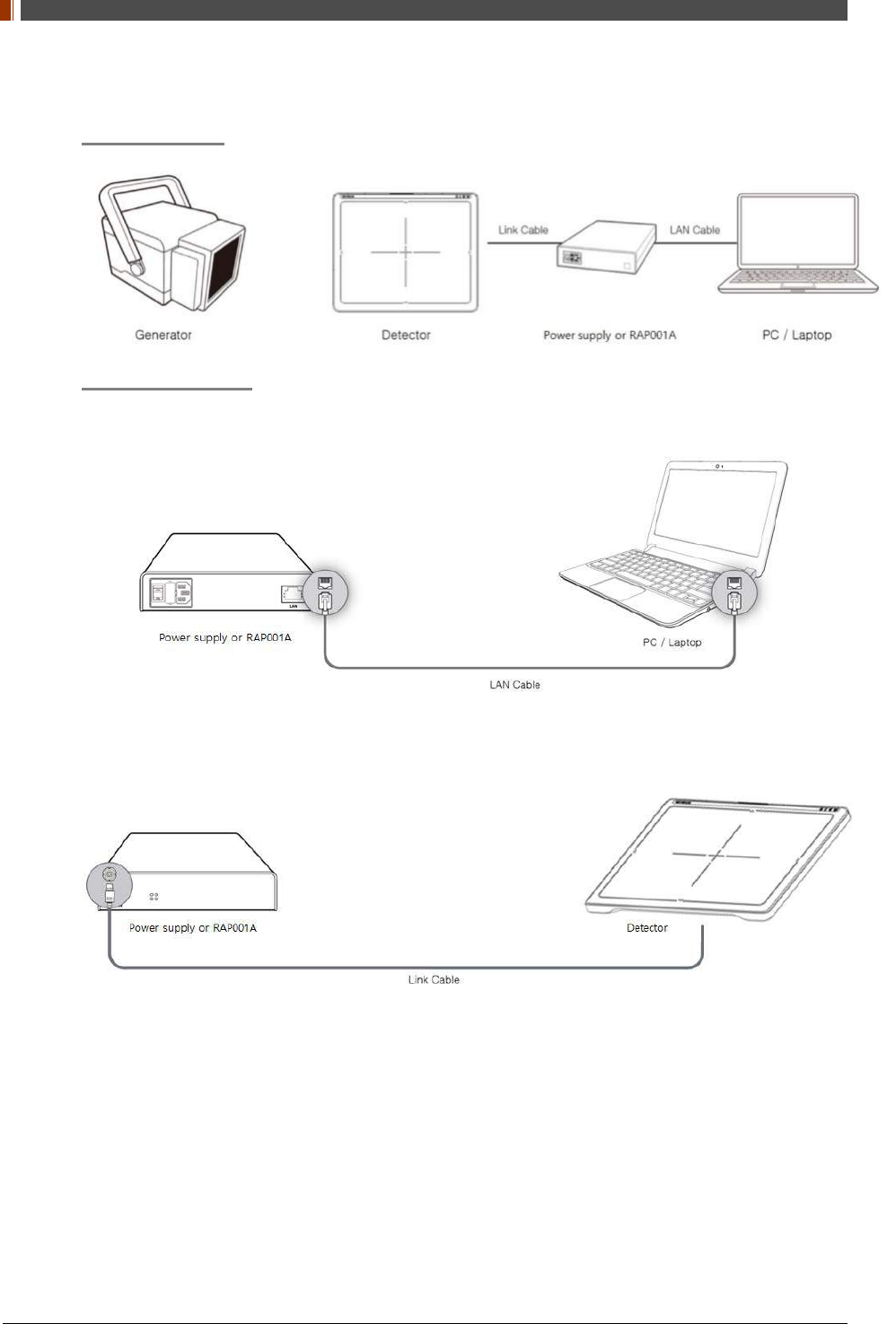
5. Auto Trigger & Wired Mode
Product Set Up
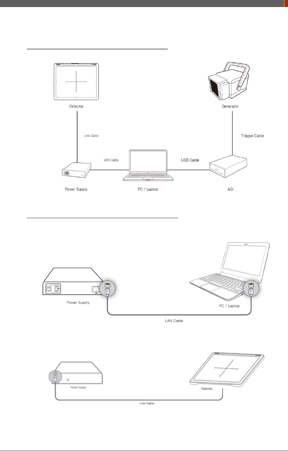
Connect the cable
1. Connect the power supply or RAP001A and PC with the LAN cable.
2. Connect the power supply and Detector with the Link cable.
PART II. Service Manual
1417WGC/WCC 79
PC Set up
1. Set up the Network as below.
• Desktop > Network Icon > Right click > Properties > Change Adaptor Settings
• Control Panel > Network and Sharing Center > Change Adaptor Settings
2. To use Wired mode, right click "Local Area Connection" and click Properties.
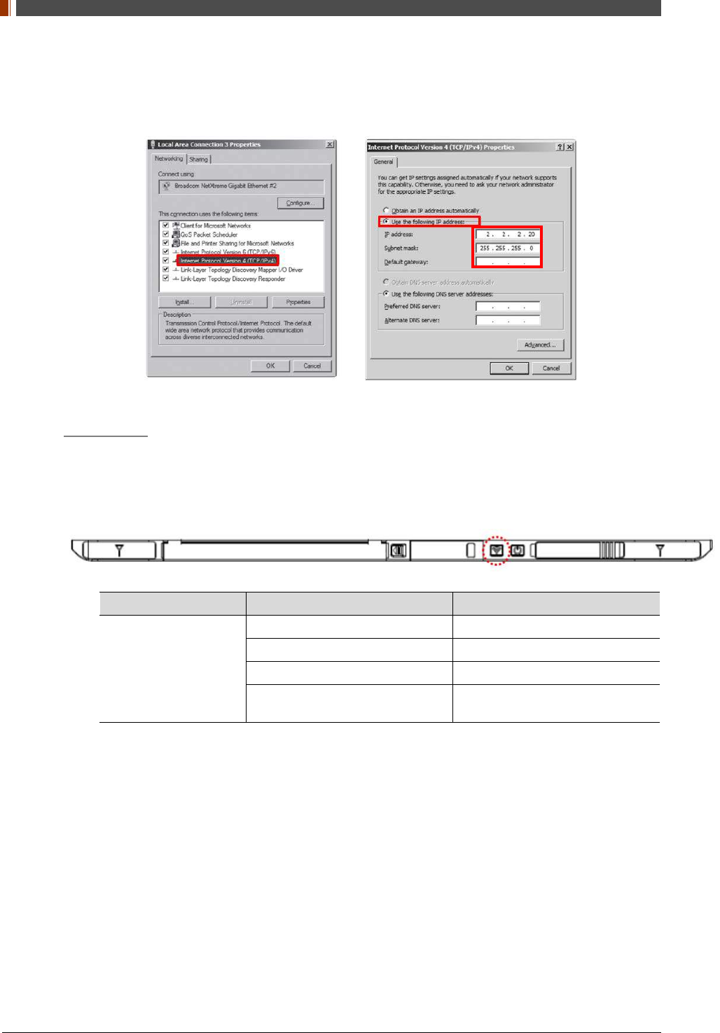
3. Double click “Internet Protocol Version 4 (TCP/IPv4)”.
PART II. Service Manual
1417WGC/WCC 80
4. Select “Use the following IP address” and type "2.2.2.20" at the "IP address" and type
"255.255.255.0" at the "Subnet mask".
Set up SW
1. Turn on the power supply or RAP001A
2. Connect the Detector to the power supply or RAP001A using the Link cable (Wired mode
will be selected automatically)
LED LED Color Mode
MODE
Orange Station Mode(Wireless)
Green AP Mode(Wireless)
None Wired Mode
Blinking Orange and Green
alternatively Sleep Mode

PART II. Service Manual
1417WGC/WCC 81
3. Open “_vadav.lnk” from “C:\davinci”.
Once the program is opened and the detector is connected, the LINK LED light will blink
and the Detector Status will display detector information as below.
Once the correct Sensor IP is put into the Davinci, it will automatically pull the
parameter of the connected detector.
Model type Parameter Selected
1417WCC _127A [69]1417WCC_127A.par
1417WCC _140A [71]1417WCC_140A.par
1417WGC _127A [70]1417WGC_127A.par
1417WGC _140A [72]1417WGC_140A.par
Default IP address for wireless connection is 2.2.2.100 and for wired connection is
2.2.2.101. If the IP address needs to be changed, please refer to 2.1 Detector IP
Address Set Up in Part.2 Service Manual.
If the detector does not communicate with the PC, please check the connection of the
cable, PC set up and power of the detector.
PART II. Service Manual
1417WGC/WCC 82
4. After checking connectivity, click the “Calibration & Acquisition” tab and click "Edit".
5. Another window will be opened as below once the “Edit” button is pressed. Select "Auto
Trigger" from "Trigger Mode". If "Window time" needs to be changed, type the value at
"Window Time" from "Setting".
In Auto trigger mode, be sure to set the "Window time" longer than an exposure
time. If the "Window time" is shorter than the exposure time, images will not be
properly acquired.
PART II. Service Manual
1417WGC/WCC 83
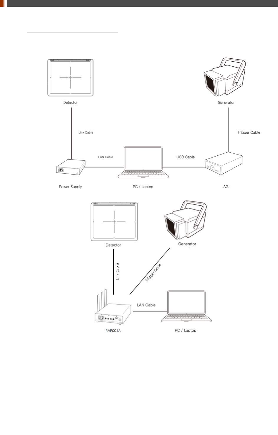
6. Manual Trigger & Wired Mode
Product Set up (with Power supply and AGI)
Connect the cable (with Power supply and AGI)
1. Connect the power supply and PC with the LAN cable.
2. Connect the power supply and Detector with the Link cable.
PART II. Service Manual
1417WGC/WCC 84
3. Connect the AGI box and PC with the USB cable.
4. Connect the AGI box and generator with the P-interface or trigger cable.
Instruction of P-interface cable Integration
<Assembly Diagram> <Timing Chart>
Instruction of Trigger cable Integration
<Assembly Diagram> <Timing Chart>
PART II. Service Manual
1417WGC/WCC 85
Product Set up (with RAP001A)
Connect the cable (with RAP001A)
1. Connect the RAP001A and PC with the LAN cable.
2. Connect the RAP001A and Detector with the Link cable.
PART II. Service Manual
1417WGC/WCC 86
3. Connect the RAP001A and generator with the P-interface or trigger cable.
Instruction of P-interface cable Integration
<Assembly Diagram> <Timing Chart>
Instruction of Trigger cable Integration
<Assembly Diagram> <Timing Chart>

PART II. Service Manual
1417WGC/WCC 87
PC Set up
1. Set up the Network as below.
• Desktop > Network Icon > Right click > Properties > Change Adaptor Settings
• Control Panel > Network and Sharing Center > Change Adaptor Settings Set up SW
`
2. To use Wired mode, right click "Local Area Connection" and click Properties.
PART II. Service Manual
1417WGC/WCC 88
3. Double click “Internet Protocol Version 4 (TCP/IPv4)”.
4. Select “Use the following IP address” and type "2.2.2.20" at the "IP address" and type
"255.255.255.0" at the "Subnet mask".
Set up SW
1. Turn on the power supply or RAP001A
2. Connect the Detector to the power supply or RAP001A using the Link cable (Wired mode
will be selected automatically)
LED LED Color Mode
MODE
Orange Station Mode(Wireless)
Green AP Mode(Wireless)
None Wired Mode
Blinking Orange and Green
alternatively Sleep Mode
PART II. Service Manual
1417WGC/WCC 89
3. Open “_vadav.lnk” from “C:\davinci”.
Once the program is opened and the detector is connected, the LINK LED light will blink
and the Detector Status will display detector information as below.
Once the correct Sensor IP is put into the Davinci, it will automatically pull the
parameter of the connected detector.
Model type Parameter Selected
1417WCC _127A [69]1417WCC_127A.par
1417WCC _140A [71]1417WCC_140A.par
1417WGC _127A [70]1417WGC_127A.par
1417WGC _140A [72]1417WGC_140A.par
Default IP address for wireless connection is 2.2.2.100 and for wired connection is
2.2.2.101. If the IP address needs to be changed, please refer to 2.1 Detector IP
Address Set Up in Part.2 Service Manual.
If the detector does not communicate with the PC, please check the connection of the
cable, PC set up and power of the detector.
PART II. Service Manual
1417WGC/WCC 90
4. After checking connectivity, click the “Calibration & Acquisition” tab and click "Edit".
5. Another window will be opened as below once the “Edit” button is pressed. Select "Manual"
from "Trigger Mode". If "Window time" needs to be changed, type the value at "Window
Time" from "Setting".
PART II. Service Manual
1417WGC/WCC 91
3.2 Calibration
In order to properly acquire images, calibration must be performed. Without calibration, optimum
images cannot be acquired.
Rayence recommends to warm up the detector for 5 minutes after turning on the
power.
Calibration should be performed at regular intervals, typically once every six (6)
months, or whenever the central beam of the X-ray source has been moved relative to
the Detector.
3.2.1 Auto Calibration Mode
1. Connect the detector and turn the power on.
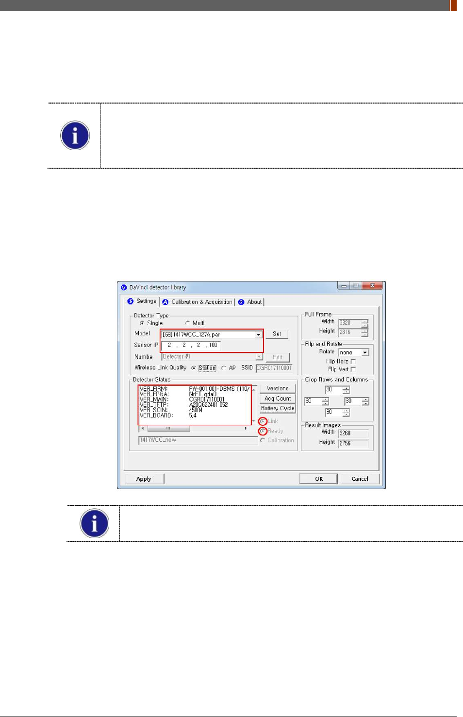
2. Open “_vadav.lnk” from “C:\davinci”.
3. Once the detector is connected, information of the detector is displayed in Detector Status
and Link & Ready are checked as below.
If "Detector Status" does not show anything, please refer to 3.1Installation in
Part.1 User & Installation Manual to connect the detector properly.
PART II. Service Manual
1417WGC/WCC 92
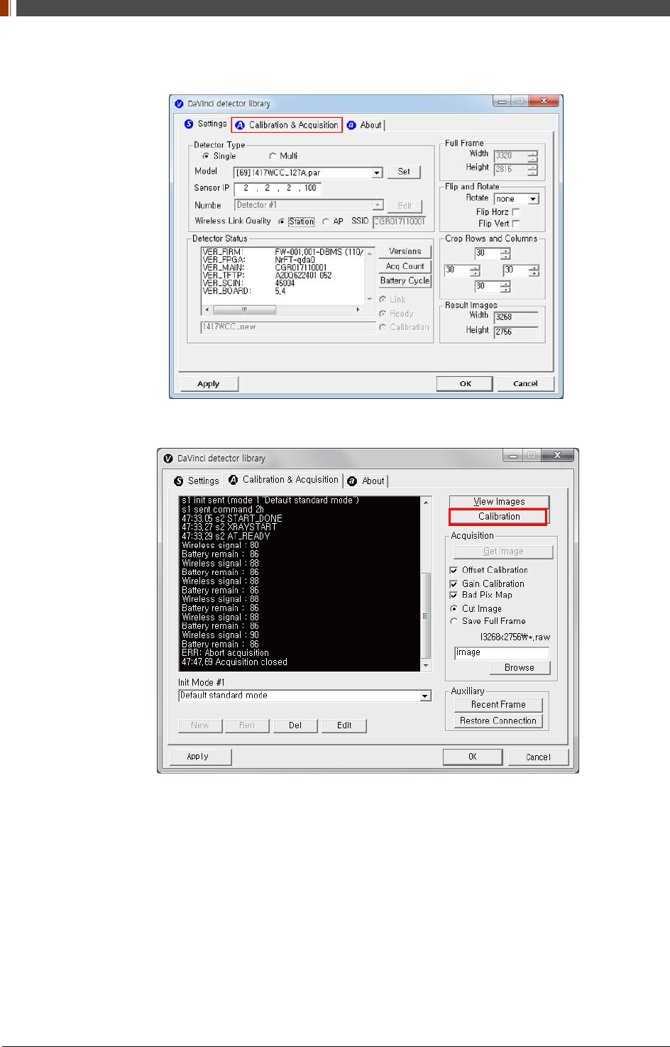
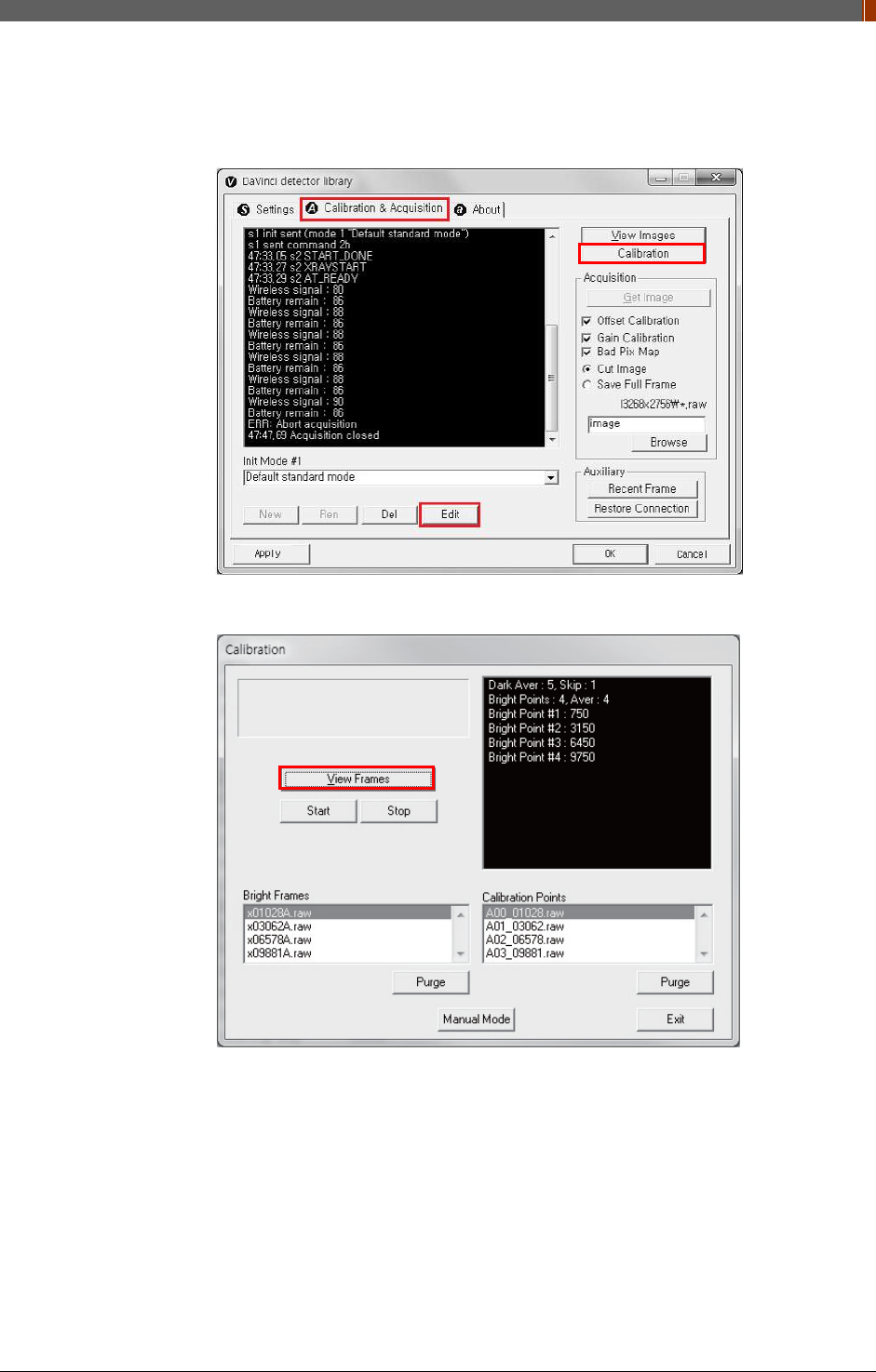
4. After checking connection, click “Calibration & Acquisition” tab.
5. Click “Calibration”.
PART II. Service Manual
1417WGC/WCC 93
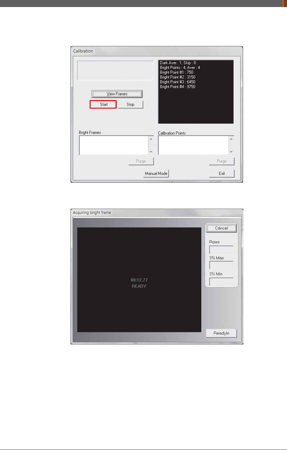
6. Once "Start” is pressed, the program automatically gets a Dark frame and the acquired
Dark frame is stored in “C:\davinci\cal”. A Calibration Point file will be created automatically.
7. After acquiring the Dark frame, shoot an X-ray when the “Acquiring bright frame” window
pops up.
PART II. Service Manual
1417WGC/WCC 94
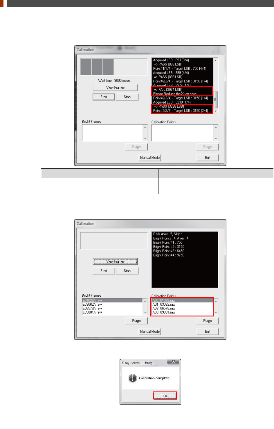
8. “Acquiring bright frame” is closed after radiation is detected, and the program will show if
the detected radiation is within acceptable range.
When PASS is displayed When FAIL is displayed
Shoot X-ray with same technique when
“Acquiring bright frame” is popped up. Adjust technique to get acceptable value and
shoot again.
9. For each Calibration point, four images must successfully be acquired. After successfully
doing so for every point, the Calibration process is complete.
10. Click "OK" to move to the next step.
PART II. Service Manual
1417WGC/WCC 95
3.2.2 Manual Bad Pixel Map Set Up
1. Click “Calibration”.
2. Click "View Frames".
PART II. Service Manual
1417WGC/WCC 96
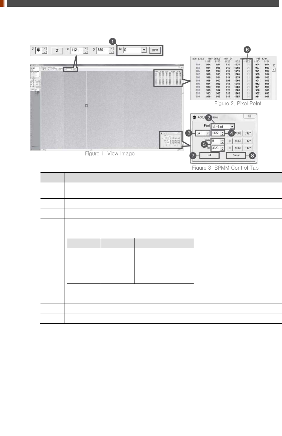
3. Set Manual bad pixel map (BPMM) as below.
No. Overview
1 At Figure 1, choose S from the list of M(
❶
) and click "BPM". Check if BPMM window is
popped up as Figure 3.
2 Choose "Bad" from Pixel list (Figure 3 -
❷
).
3 Choose either “row” or “col” from Figure 3 -
❸
.
4 Put the coordinate of pixel to set bad pixel at Figure 3 -
❹
.
5
If bad pixel is a line, put the range as below at Figure 3 –
❺
.
From To
Row 0 3327(127type)
2449(140type)
Col 0 2815(127type)
3051(140type)
If bad pixel is not a line but some pixels, put the rest coordinate at Figure 3 -
❺
.
6 After completing step 5 , check if bad pixel has been changed to green as Figure 2 -
❻.
7 Click “Fill” at Figure 3 -
❼
.
8 Click "Save" at Figure 3 -
❽
.
4. Once setting BPMM is done, “BPMM.raw” file will be saved at C:\Davinci\CAL.
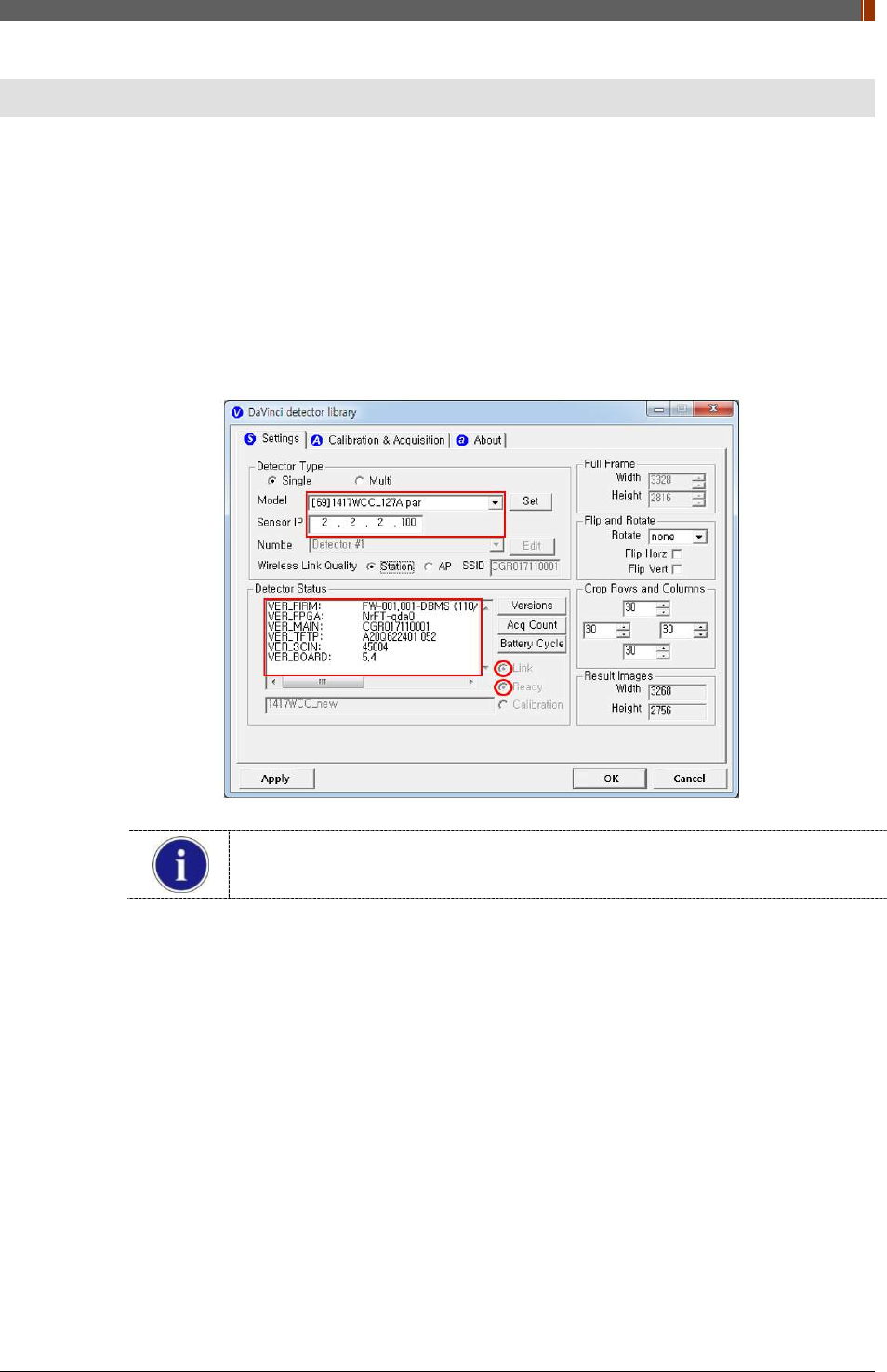
PART II. Service Manual
1417WGC/WCC 97
4. Usage
4.1 Set Up
4.1.1 Product Connectivity
1. Connect the detector and turn on the power.
2. Open “_vadav.lnk” from “C:\davinci”.
3. Once the detector is connected, detector information is displayed in Detector Status and
Link & Ready are checked as below.
If "Detector Status" does not show anything, please refer to 3.1 Installation in
Part.1 User & Installation Manual to connect the detector properly.
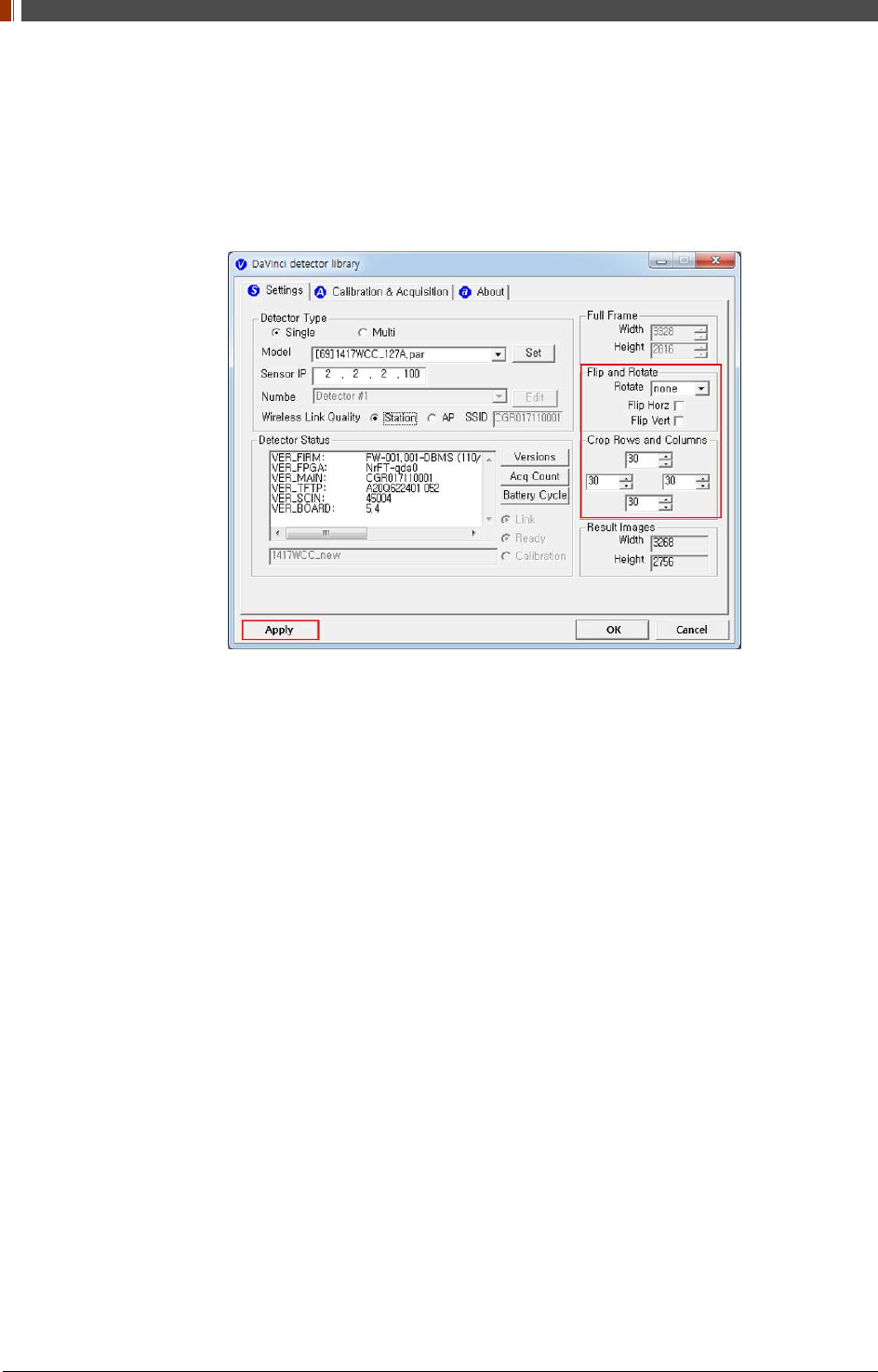
PART II. Service Manual
1417WGC/WCC 98
4.1.2 Image Set Up
1. In order to rotate or flip an image, use the option of "Flip and Rotate" as shown below.
2. In order to change the size of an image, use "Crop Rows and Columns" as below.
3. Click "Apply" to save.
4.1.3 Multi Detector Set Up
Refer to 3 Multi Detector Set Up in Part.2 Service Manual for Multi-Detector Setting.
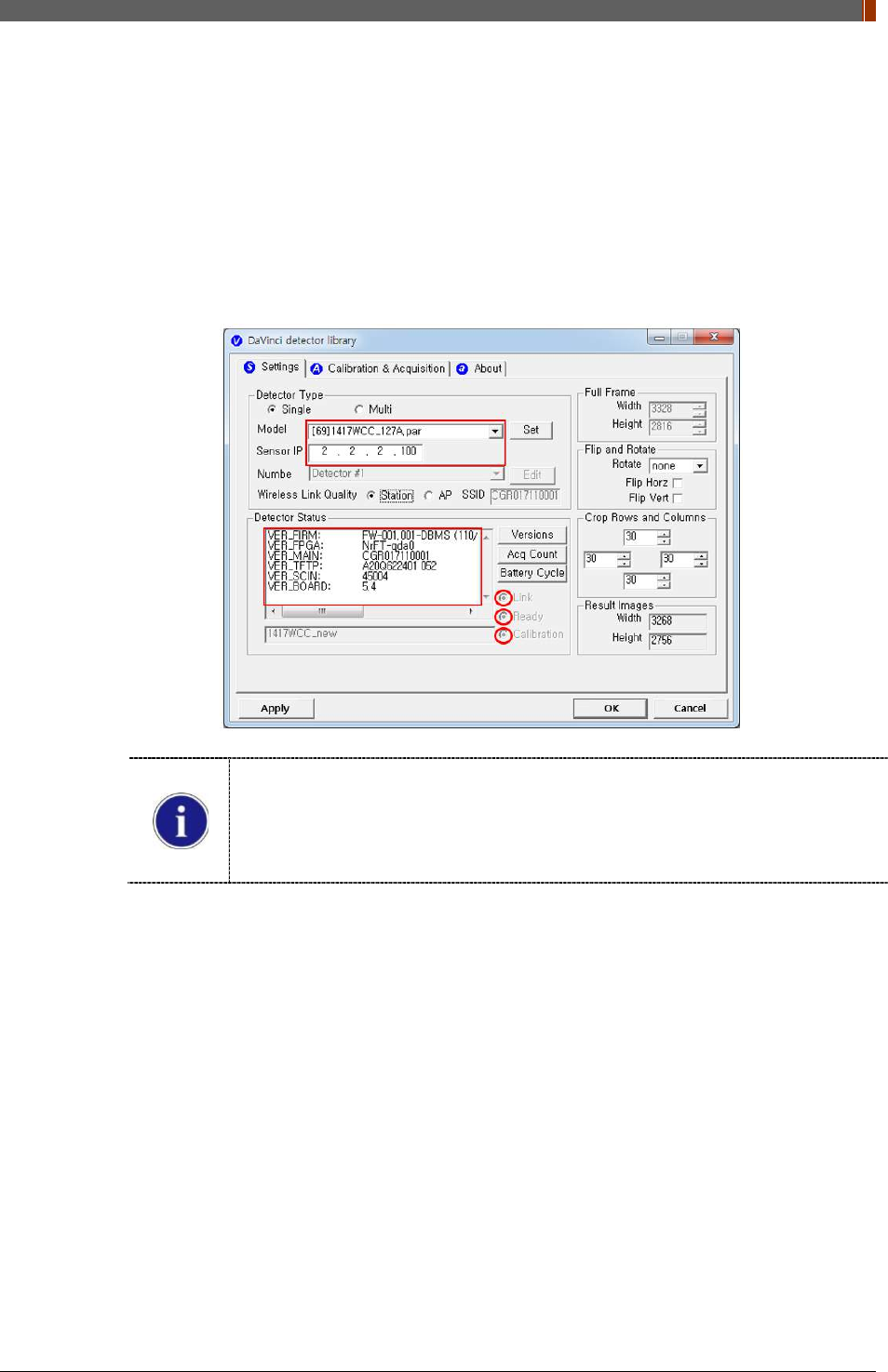
PART II. Service Manual
1417WGC/WCC 99
4.2 Image Acquisition
4.2.1 Product Connection
1. Connect the detector and turn on the power.
2. Open “_vadav.lnk” from “C:\davinci”.
3. Once the detector is connected, information of the detector is displayed in Detector Status
and Link & Ready & Calibration are checked as below.
If "Detector Status" does not show anything, please refer to 3.1 Installation in
Part.1 User & Installation Manual to connect the detector properly.
If Calibration is not checked along with black dots checking off "Link" and "Ready"
as above, please refer to 3.2 Calibration in Part.1 User & installation Manual and
perform calibration again.
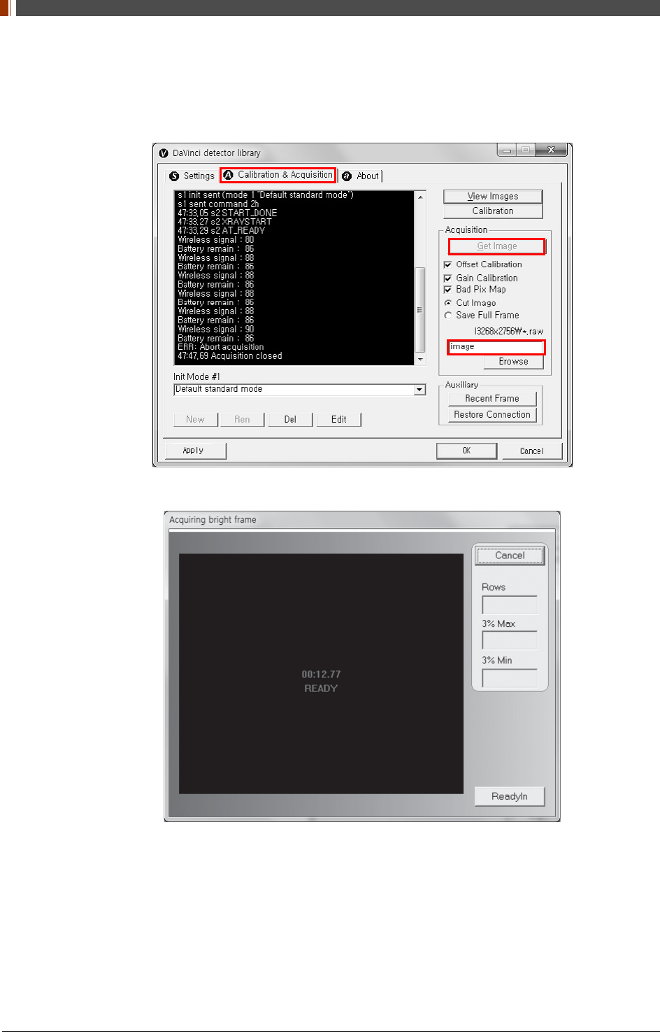
PART II. Service Manual
1417WGC/WCC 100
4.2.2 Image Acquisition
1. Click the "Calibration & Acquisition” tab and type the name of the image inside the box
below. After naming the image, click “Get Image”.
2. Shoot an X-ray once the "Acquiring bright frame" window pops up.
3. An acquired image will be stored in “C:\davinci\I.3268x2756 (127type) or 2440x2992
(140type)” and the name of the file will be "(typed name from Step 1).raw”.
4. The format of the stored file is 16 bit little-endian order.
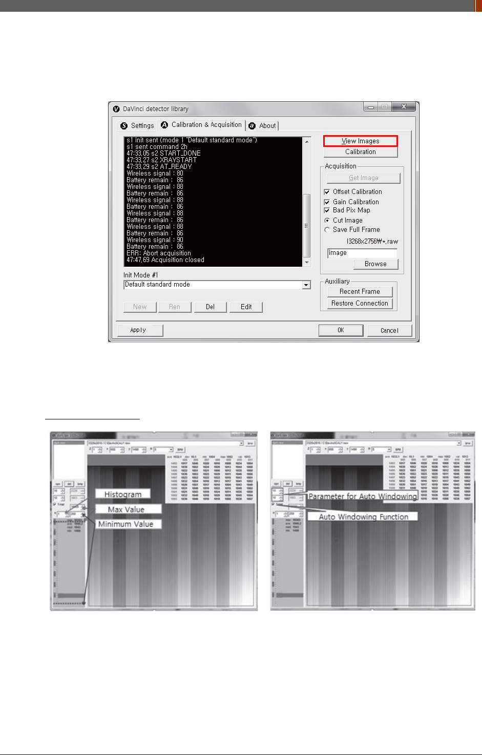
PART II. Service Manual
1417WGC/WCC 101
4.3 View Images
1. Click “View Images”
2. Another window will be popped up as below.
Histogram Set Up
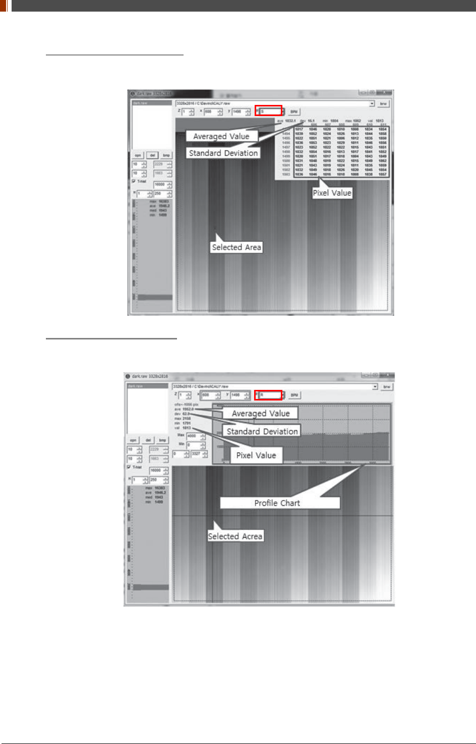
PART II. Service Manual
1417WGC/WCC 102
Pixel value at certain level
Choose "S" from marked box.
Profile for horizontal line
Choose "R" from marked box.
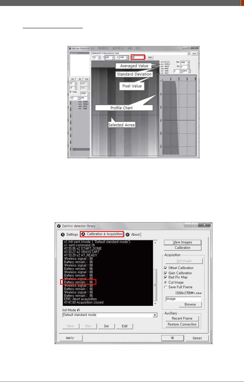
PART II. Service Manual
1417WGC/WCC 103
Profile for vertical line
Choose "C" from the marked box.
4.4 Additional Function
4.4.1 Battery Remain
Once you click "Get Image" under the "Calibration & Acquisition” tab, the Status window will
show how much battery remains.
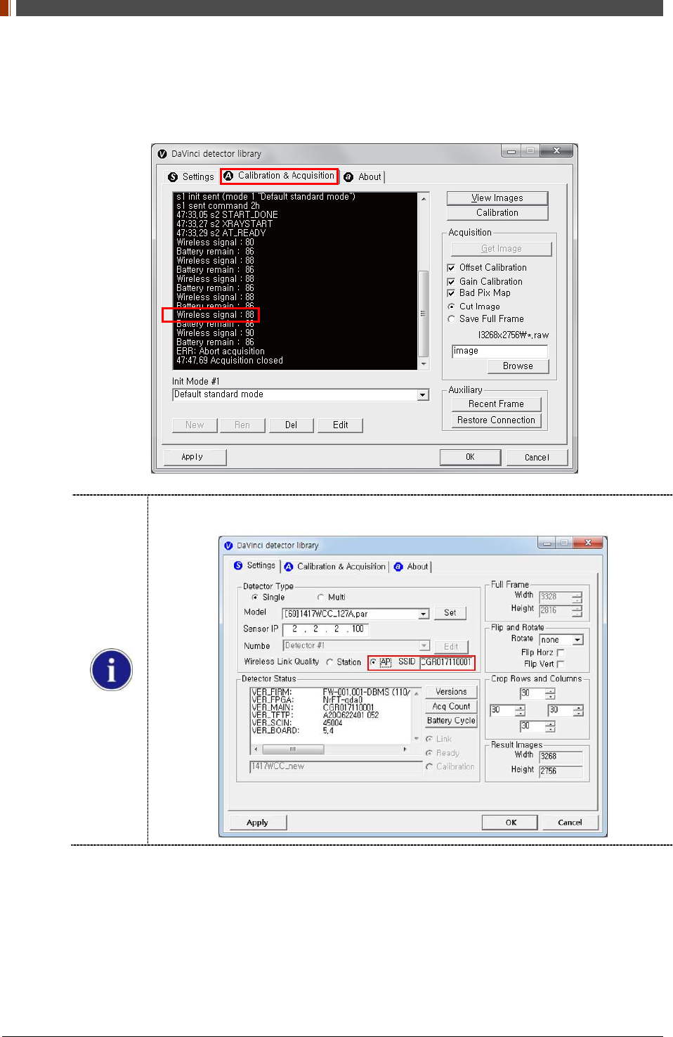
PART II. Service Manual
1417WGC/WCC 104
4.4.2 Wireless signal Strength
Once you click "Get Image" under the "Calibration & Acquisition” tab, the Status window will
show the strength of the wireless signal.
Before you check the wireless signal in the AP mode, the detector's serial number should
be entered at the "SSID".
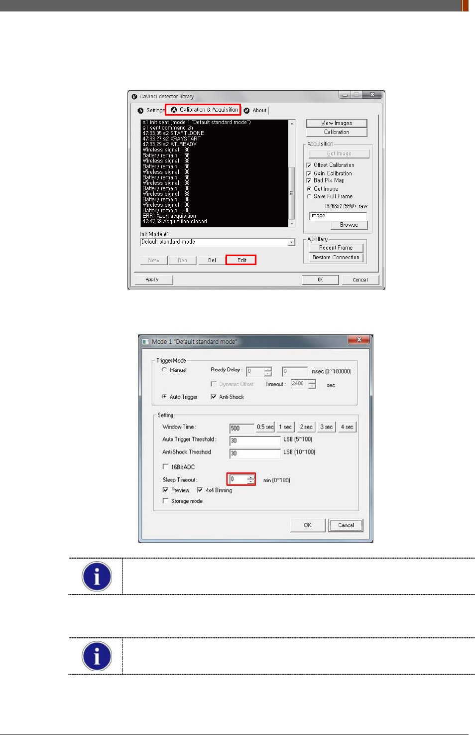
PART II. Service Manual
1417WGC/WCC 105
4.4.3 Sleep Mode
1. Click “Edit” under the Calibration & Acquisition tab.
2. Under the “Sleep Timeout” setting, enter a designated time for the detector to go into Sleep
Mode.
Sleep Mode does not apply when set to zero.
3. To turn off Sleep Mode, attempt to acquire an image or press the power button on the
detector just once.
A normal image can be acquired after 10 seconds Sleep Mode has been turned
off.
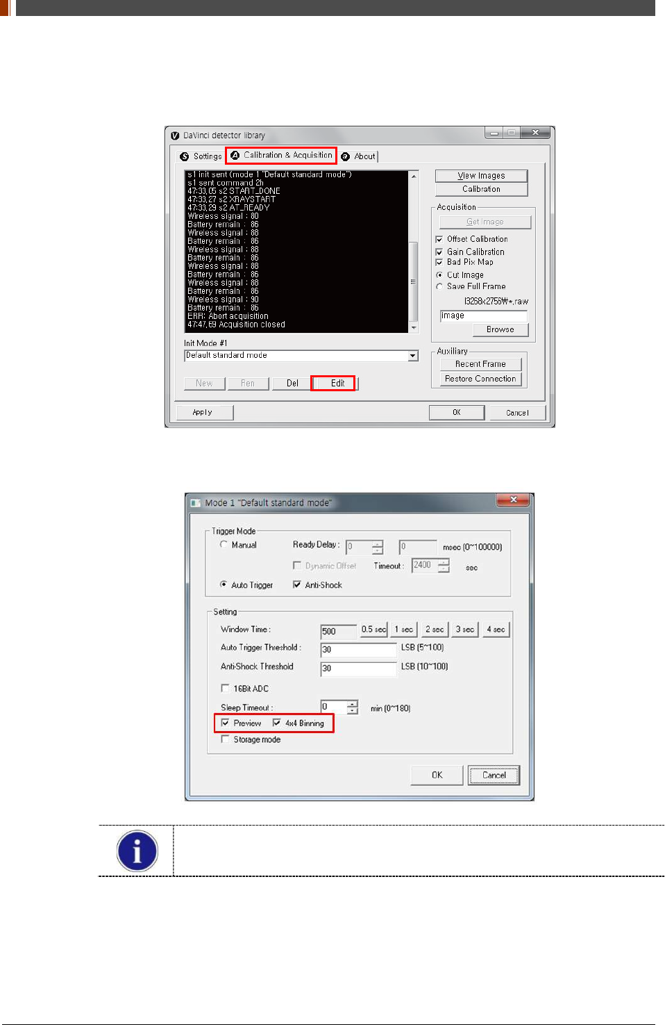
PART II. Service Manual
1417WGC/WCC 106
4.4.4 Preview
1. Click “Edit” under the Calibration & Acquisition tab.
2. After checking the Preview and 4x4 Binning, a 4x4 binned image appears which allows for
a quicker image preview.
By unchecking 4x4 Binning, a normal image preview appears.
By unchecking Preview, a full frame image appears.
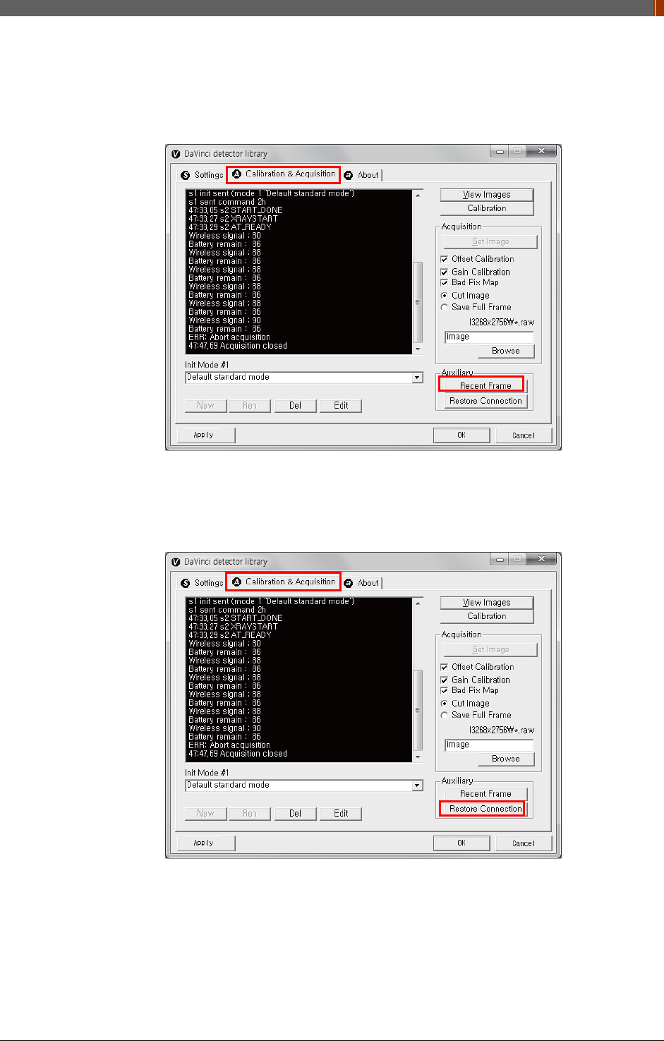
PART II. Service Manual
1417WGC/WCC 107
4.4.5 Recent Frame
The last acquired image can be opened by clicking "Recent Frame" under the "Calibration &
Acquisition” tab.
4.4.6 Restore Connection
When the connection between the detector and PC is lost, the connection can be made again
by clicking "Restore Connection" under the "Calibration & Acquisition” tab.
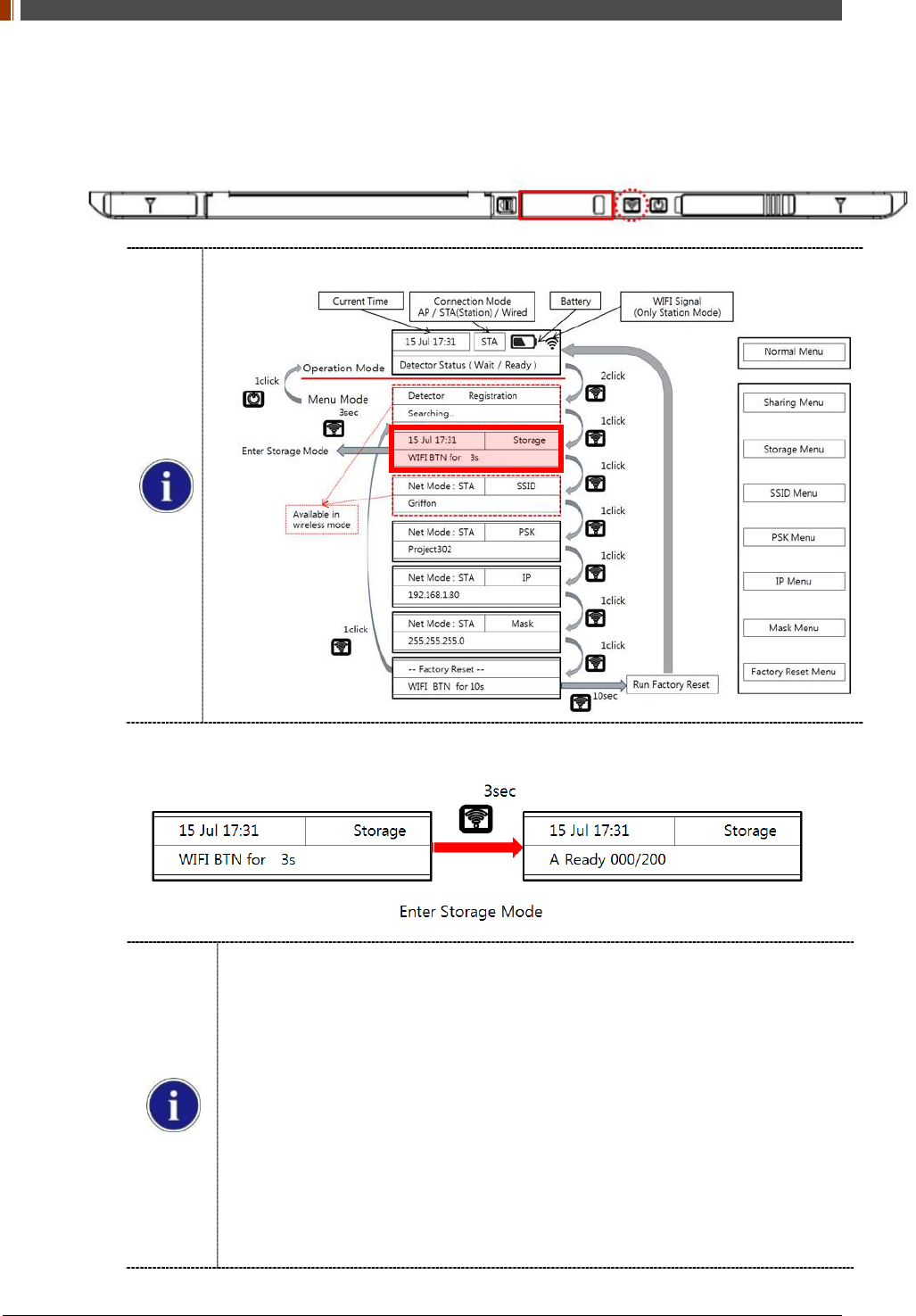
PART II. Service Manual
1417WGC/WCC 108
4.4.7 Image Storage function
1. Press the "Mode select button" twice (within 2 seconds) and click one more time to go to
"storage mode".
Mode status can be checked by the OLED window of Detector
2. Press the mode select button for 3 seconds to check the status of storaged images.
When Storage mode is used if the connection between the detector and PC,
the image is stored the memory in the Detector internal
When Mobile sevice connects to Detector, can check correctly Image by
Storage Viewer Web Server
For Storage Viewer, must running DBMS and Web Server envirnoment
If disable ‘0x1e’ parameter by VADAV, running DBMS and Web Server
environment durning Detector boot up
If enable ‘0x1e’ parameter by VADAV, running DBMS and Web Server
environment during enter Storage Mode menu
Parameter ‘0x1e’ is Storage Function Disable
For running Storage Viewer environment, OLED is displayed “Check DB
Server”
Stored Image can be opened and deleted by referring SDK
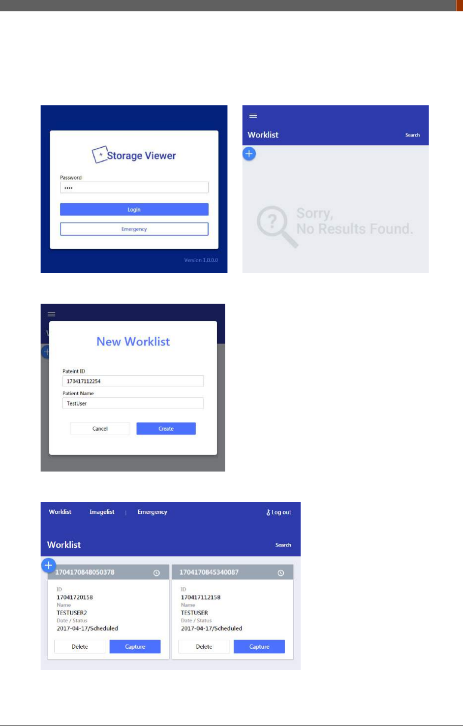
PART II. Service Manual
1417WGC/WCC 109
A. Mobile Device can connect to Detector’s AP Mode
B. Connect to "http://192.168.1.80:3000". Sign in with password ‘1234’
C. Ater enter to worklist menus, click ‘+’ icon and create worklist info.
D. Input to space Patient ID/Name info that will be insert to image info.
E. Can see all worklist for will acquire image. Click ‘Capture’ button.
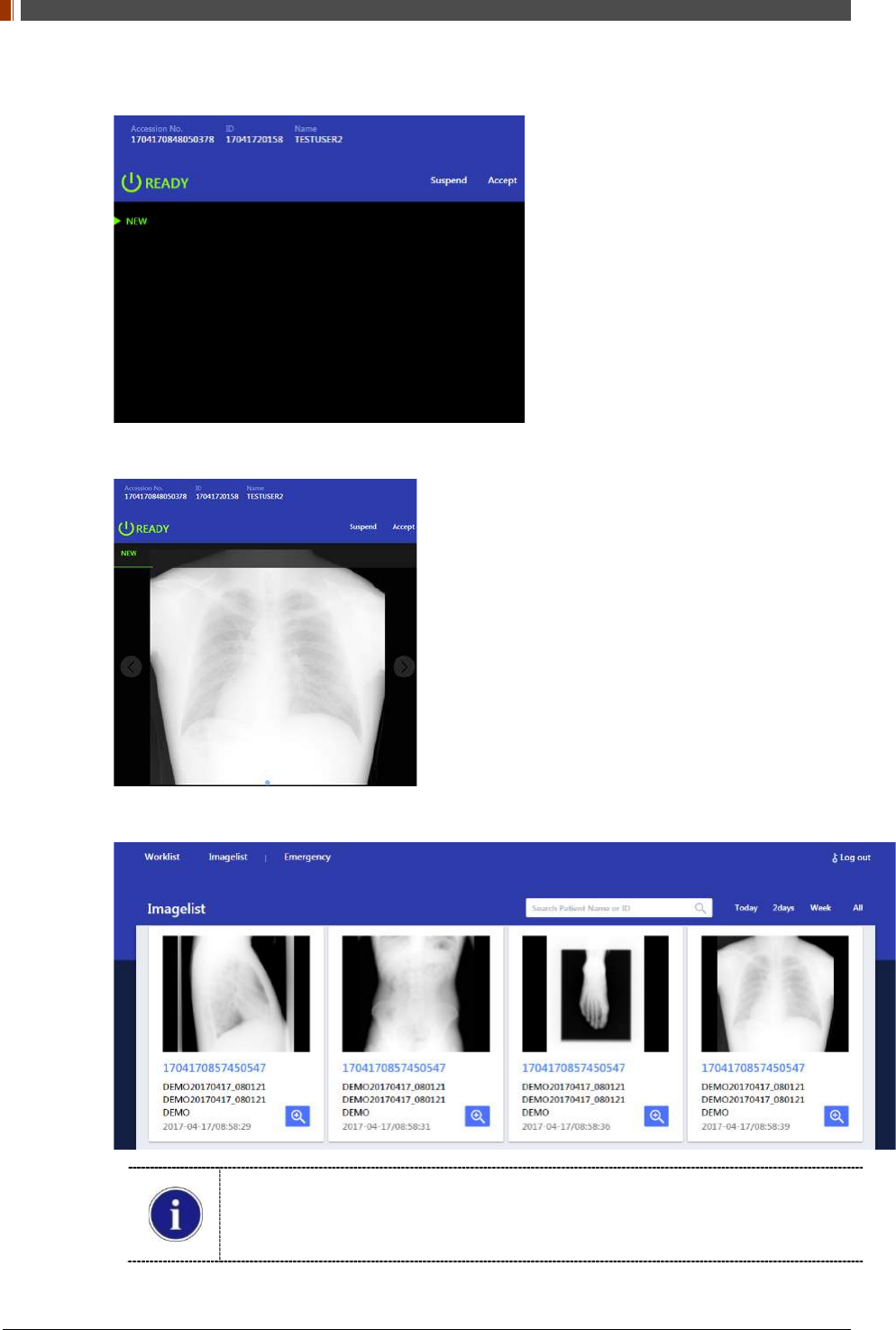
PART II. Service Manual
1417WGC/WCC 110
F. In detector ready status, can take X-ray image.
G. Shot X-ray Show image and can check correct Select Accept/Suspend button
H. Show all acquisition image list on Storage Mode
When worklist menu is empty, detector will be created woklist menu and matching
Some guide image is created by web server demo mode
After 180 days of acquisition, image is automatically deleted
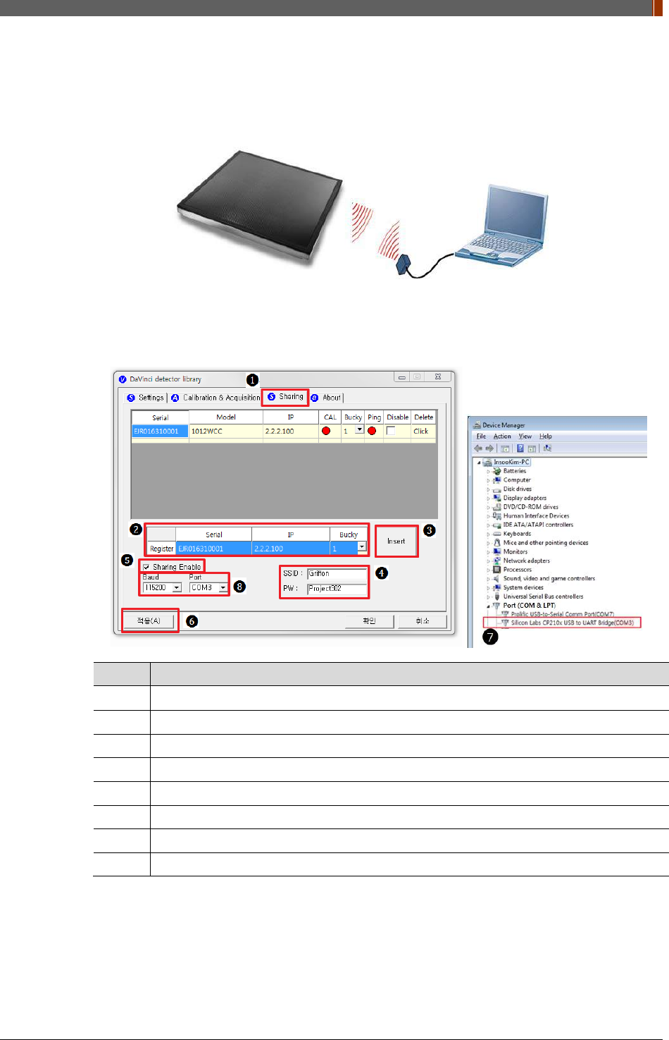
PART II. Service Manual
1417WGC/WCC 111
4.4.8 Sharing function
1. Connect the PC and USB IrDA Dongle by using the Micro USB cable.
2. Set vadavas below
No. Overview
❶
Click “sharing” tab
❷
Enter follow thing in order “serial number, IP, bucky number”
❸
Click “insert”
❹
Put the SSID and PW of AP
❺
Check “Enable check box”
❻
Click “apply” to save
❼
Confirm the connection port in device manager of OS
❽
Baud select 115200 and select confirmed port in device manager
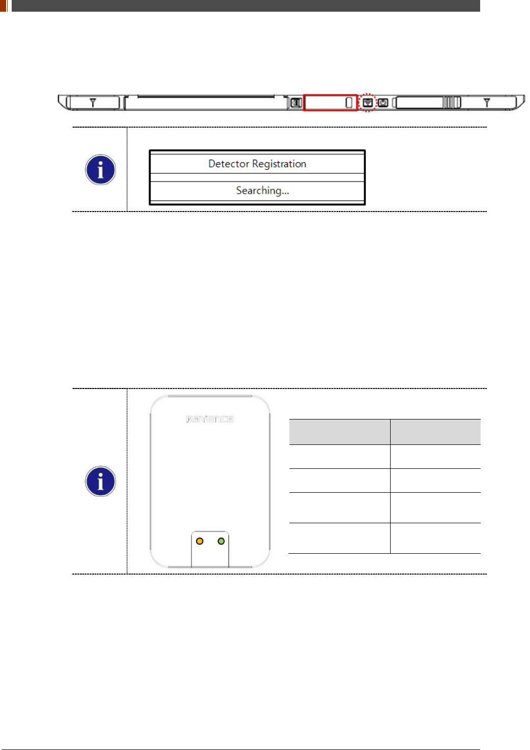
PART II. Service Manual
1417WGC/WCC 112
3. Press the "Mode select button" turn on the detector twice (within 2 seconds) and transfer to
"sharing mode".
Mode status can be checked by the OLED window of Detector
4. When approaching the detector with USB IrDA connecting to the PC, transfer the Serial
Number information of detector.
5. Based on the transmitted Serial Number, the CAL folder at the PC is created and the
shooting condition is set then USB IrDA of PC transfers IP/SSID information with Detector.
6. Detector sets the shooting conditions with the IP/ received SSID.
STA Mode: Detector is set by information of wireless router.
AP Mode: PC connects to S/N AP Host name’s wireless router (Detector).
7. If the shooting condition setting is completed, completion status appears at the "OLED
window" and "Sharing mode" is turn off.
IrDA LED Color Status
Green Connected PC
Blinking Orange Transfer the data
End Blinking
Turn on Green Transfer success
End Blinking
Turn off Green Transfer fail
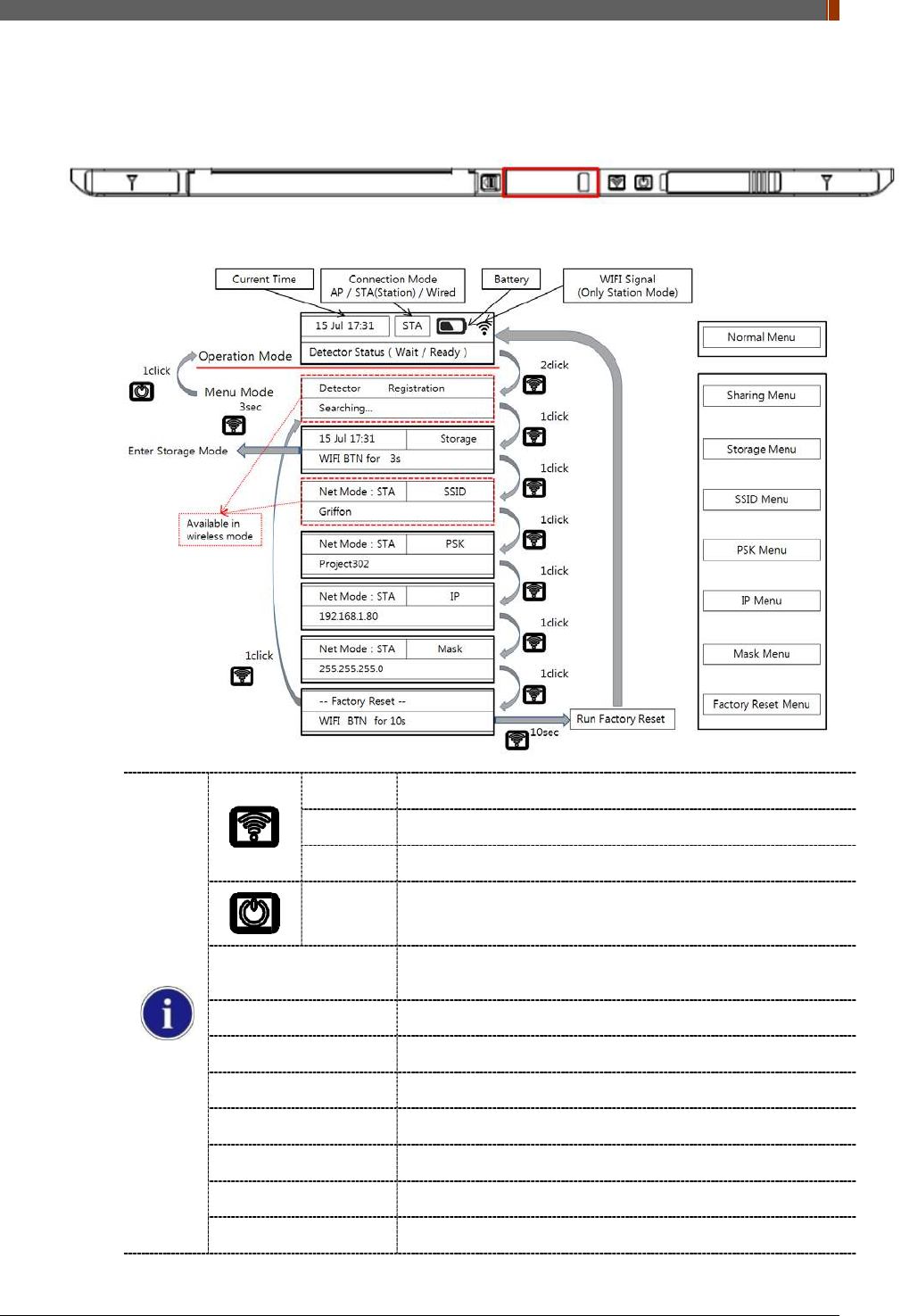
PART II. Service Manual
1417WGC/WCC 113
4.4.9 OLED function
1. OLED is operating when detector is turned on.
2. Use the Mode select button and Power button can be used OLED function as follows.
1 click Press the mode select button
2 click Press the mode select button twice (within 2 seconds)
10 sec Press the mode select button for 10 seconds
1 click Press the power button
Normal menu - Will Show the (Time / Battery remain / Wireless signal) of
detector
Sharing menu - Operation the “sharing function”
Storage menu - Operation the “storage function”
SSID menu - Will Show the SSID information of detector
PSK menu - Will Show the PSK information of detector
IP Menu - Will Show the IP information of detector
Mask menu - Will Show the Mask information of detector
Factory reset menu - Factory reset menu

PART II. Service Manual
1417WGC/WCC 114
5. Maintenance
5.1 Cleaning
1. Clean the detector with IPA (Isopropyl-alcohol) when it is contaminated.
2. Before cleaning the detector, turn off the power and separate the battery.
3. Wear waterproof gloves to protect your hands from direct contact with IPA or any other
liquid.
4. Do not pour or spray IPA directly on the detector. Use fabric or soft cloth moistened with IPA
to clean.
5. Avoid getting IPA or any other liquid into the detector.
6. After cleaning, wait until the IPA is dried completely.
5.2 Inspection
1. In order to ensure that the detector is used safely and normally, please be sure to inspect
the product regularly before use. If any problem occurs, please contact Rayence Customer
Service team.
2. Please perform inspections based on the check list below.
Inspection List User Vendor Cycle
Check if cables are not damaged o Daily
Check if plugs and connectors are not loose or
damaged o Daily
Check if cover or part is not damaged o Daily
Check the LED indicator o Daily
Re-Calibration o Half Year
Check the performance of the product by doing test
shots with Phantom or resolution chart o Yearly
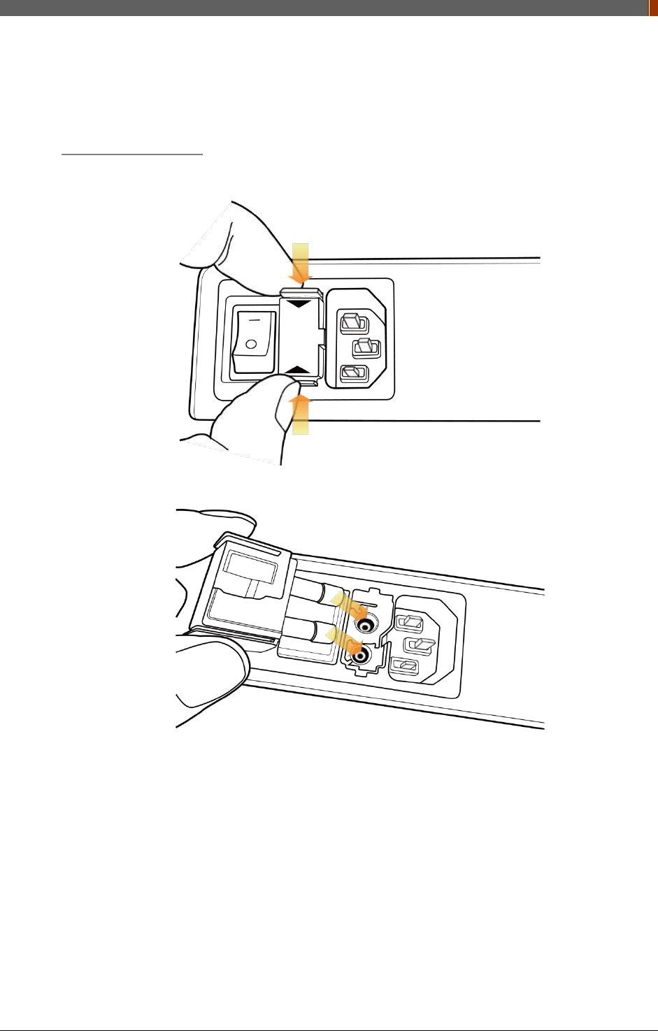
PART II. Service Manual
1417WGC/WCC 115
5.3 Replaceable Parts and Instruction of Replacement
5.3.1 Fuse: T3.15 AL 250V
Replacing the Fuse
1. Press the fuse as below and pull the fuse box.
2. Pull the fuse and replace with another fuse.
5.3.2 Power cord: H05VV-F 0.75SQ * 3C
5.3.3 Ethernet Cable: UTP 4PR 24AWG (CAT.6, straight-through)

PART II. Service Manual
1417WGC/WCC 116
5.4 Disposal or Recycling
Follow local governing ordinances and recycling plans regarding the disposal or recycling of
device components.
Disposal of old Electrical & Electronic Equipment
(Application in the European Union and other European countries with separate
collection system.) This symbol indicates that this product shall not be treated as
household waste. Instead, it shall be handed over to the applicable collection point
for the recycling of electrical and electronic equipment. By ensuring this product is disposed of
correctly, you will help prevent potential negative consequences for the environment and human
health, which could otherwise be caused by inappropriate waste handling of this product. For
more detailed information about recycling this product, please refer to local governing
ordinances and recycling plans.

PART II. Service Manual
1417WGC/WCC 117
6. Warranty
6.1 Warranty
If Buyer promptly notifies RAYENCE or Seller regarding any parts that fail to perform as
specified under normal usage during the Warranty Period and RAYENCE determines that such
failure resulted from a defect in materials or workmanship during the Warranty Period, then
RAYENCE, at its option, shall repair, rebuild or adjust the affected parts.
RAYENCE shall have no obligation for any defects to the extent that such defect arises out of (i)
normal and fair wear and tear or Product which has been modified without RAYENCE's
approval, (ii) Product which has not been installed in strict conformity to the RAYENCE's
directions or which have been subjected to electrical or other abuse, or damaged by improper
handling, storage or use by Buyer or a third party, (iii) use of Product in combination with
devices or products not purchased from RAYENCE; (iv) use or application of Product in a field
or in an environment for which such Product was not designed or contemplated; (v) use of any
parts or material not provided by RAYENCE for warranty service; or (vi) the third party’s
maintenance not certified by RAYENCE; or (vii) force majeure such as natural disaster.
The remedies contained in this warranty are Buyer’s exclusive remedies. RAYENCE shall not,
in any event or under any circumstances, be responsible for damages or other sums in excess
of the total purchase price actually paid by Buyer to Seller i.e., RAYENCE or RAYENCE’s
authorized agent. Without limiting the generality of the foregoing under no circumstance shall
RAYENCE be responsible or liable in any regard with respect to damages from loss of use, loss
of time, loss of data, inconvenience, commercial loss, lost profits or savings, or other incidental,
special or consequential damages claimed by Buyer to arise out of the use or inability to use the
Product, even if Buyer has been advised of the possibility of such damages.
In the event that the product is returned to RAYENCE after the warranty has expired, RAYENCE
reserves the right to invoice a reasonable fee for the repair services provided to Buyer.
RAYENCE shall make the sole final determination about whether the fail to perform occurred in
normal usage (under warranty) or not (excluded from warranty). If the authorized agent or the
Buyer doesn’t accept the result of RAYENCE’s investigation, the burden of proof is on them.
Warranty Procedure
If Buyer needs to make a claim based on this Warranty, Buyer should advise Seller in writing
immediately at the following address:
RAYENCE Co., Ltd.
14, Samsung 1-ro 1-gil, Hwaseong-si, Gyeonggi-do, Korea
Tel: +82-31-8015-6245
Fax: +82-31-8015-6300
E-mail: marketing@rayence.com
www.rayence.com

14, Samsung 1-ro 1-gil, Hwaseong-si, Gyeonggi-do, Korea
Tel: +82-31-8015-6245 Fax: +82-31-8015-6300 E-mail: marketing@rayence.com
www.rayence.com