Rayence RYRWM001A Wireless LAN Module User Manual 1417WCC WGC
Rayence Co., Ltd. Wireless LAN Module 1417WCC WGC
Rayence >
Contents
- 1. User Manual
- 2. Host User Manual Part 1
- 3. Host User Manual Part 2
Host User Manual Part 2
PART I. User & Installation Manual
98 1417WGC/WCC
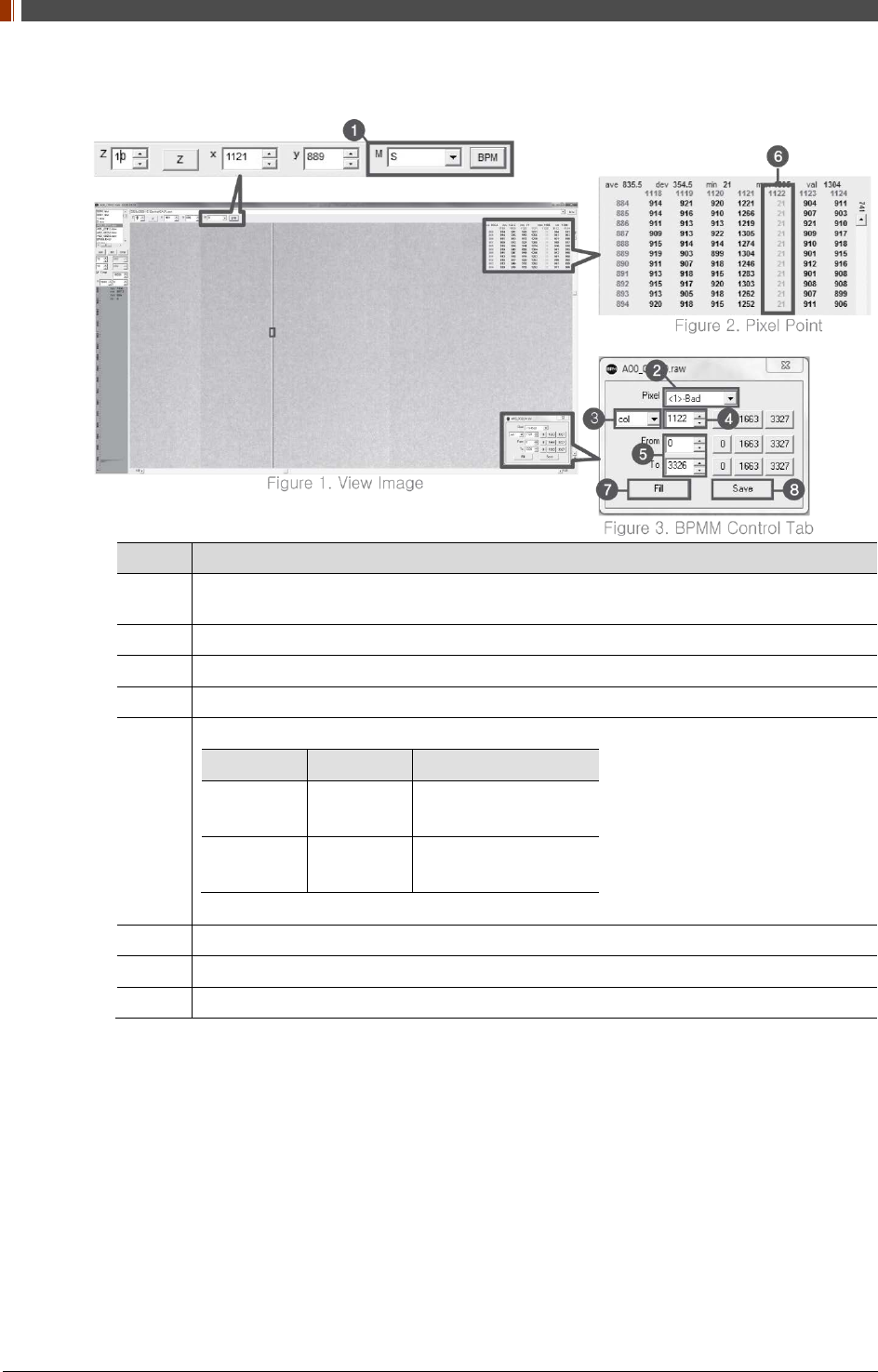
3. Set Manual bad pixel map (BPMM) as below.
No. Overview
1 At Figure 1, choose S from the list of M(
❶
) and click "BPM". Check if BPMM window is
popped up as Figure 3.
2 Choose "Bad" from Pixel list (Figure 3 -
❷
).
3 Choose either “row” or “col” from Figure 3 -
❸
.
4 Put the coordinate of pixel to set bad pixel at Figure 3 -
❹
.
5
If bad pixel is a line, put the range as below at Figure 3 –
❺
.
From To
Row 0 3327(127type)
2449(140type)
Col 0 2815(127type)
2992(140type)
If bad pixel is not a line but some pixels, put the rest coordinate at Figure 3 -
❺
.
6 After completing step 5 , check if bad pixel has been changed to green as Figure 2 -
❻.
7 Click “Fill” at Figure 3 -
❼
.
8 Click "Save" at Figure 3 -
❽
.
4. Once setting BPMM is done, “BPMM.raw” file will be saved at C:\Davinci\CAL.
PART I. User & Installation Manual
1417WGC/WCC 99
4. Usage
4.1 Set Up
4.1.1 Product Connectivity
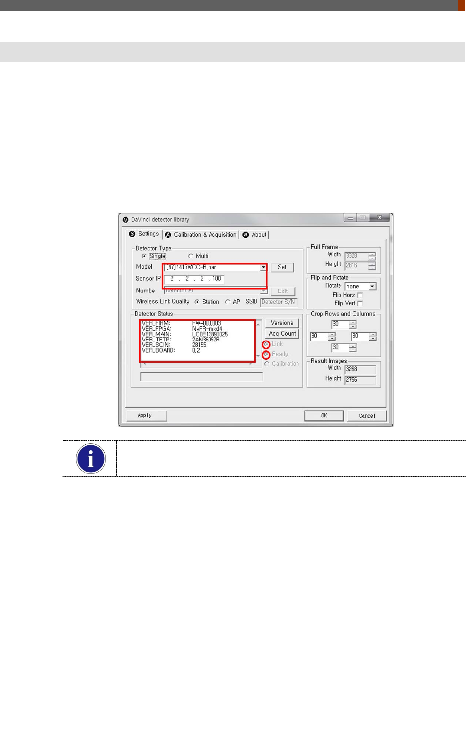
1. Connect the detector and turn on the power.
2. Open “_vadav.lnk” from “C:\davinci”.
3. Once the detector is connected, detector information is displayed in Detector Status and
Link & Ready are checked as below.
If "Detector Status" does not show anything, please refer to 3.1 Installation in
Part.1 User & Installation Manual to connect the detector properly.
PART I. User & Installation Manual
100 1417WGC/WCC
4.1.2 Image Set Up
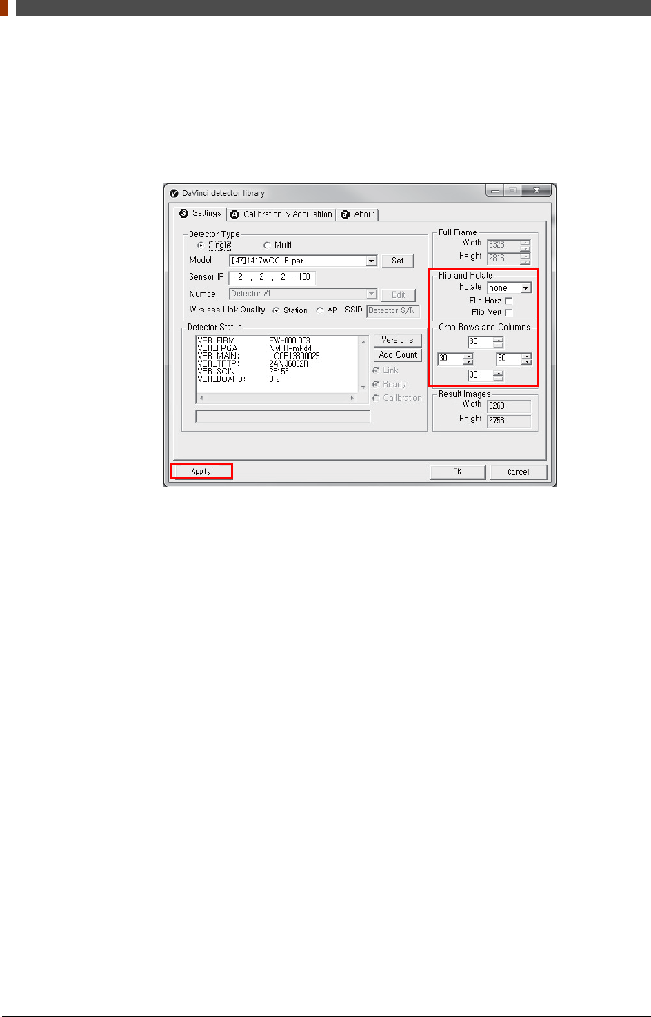
1. In order to rotate or flip an image, use the option of "Flip and Rotate" as shown below.
2. In order to change the size of an image, use "Crop Rows and Columns" as below.
3. Click "Apply" to save.
4.1.3 Multi Detector Set Up
Refer to 3 Multi Detector Set Up in Part.2 Service Manual for Multi-Detector Setting.
PART I. User & Installation Manual
1417WGC/WCC 101
4.2 Image Acquisition
4.2.1 Product Connection
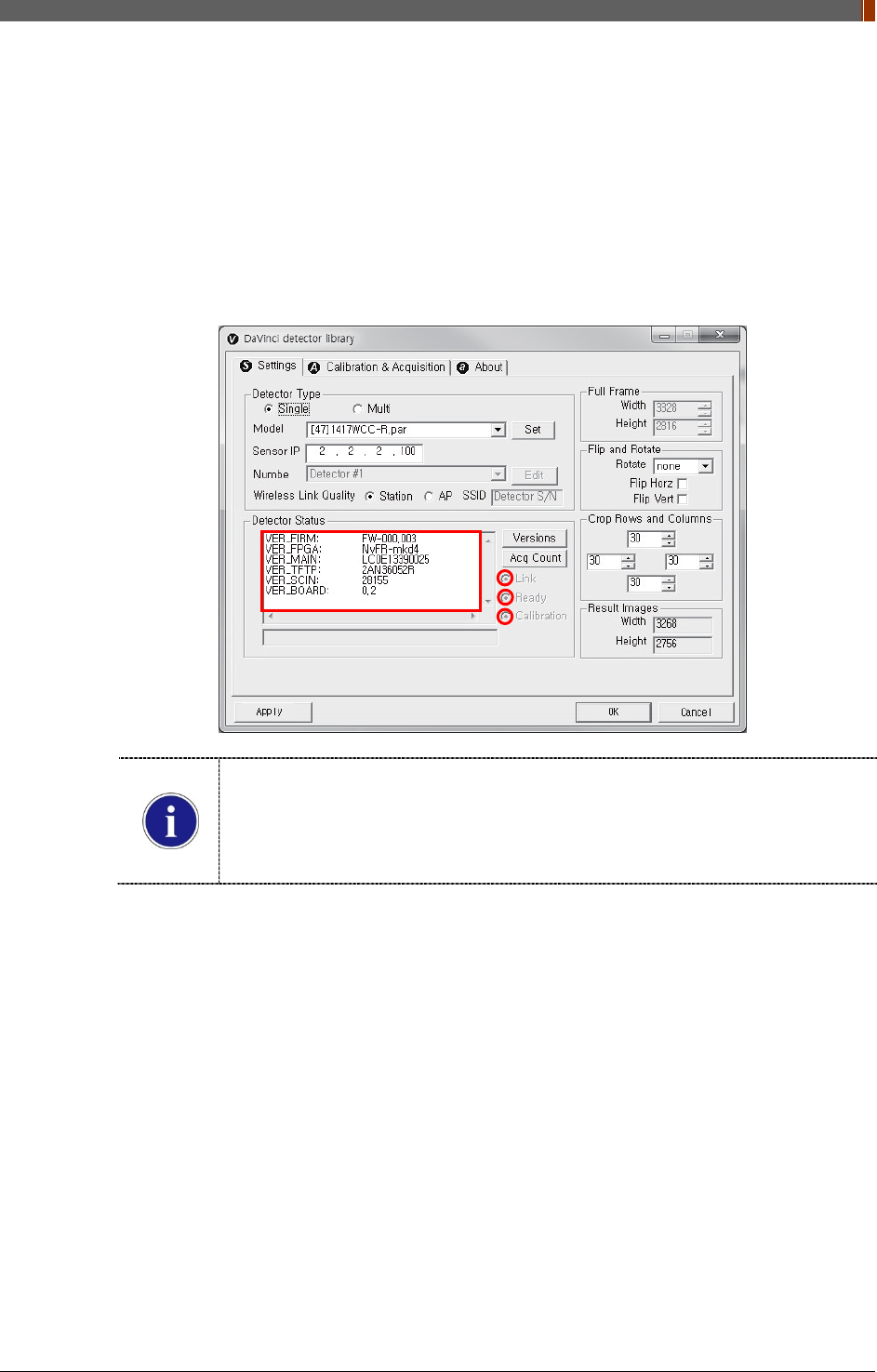
1. Connect the detector and turn on the power.
2. Open “_vadav.lnk” from “C:\davinci”.
3. Once the detector is connected, information of the detector is displayed in Detector Status
and Link & Ready & Calibration are checked as below.
If "Detector Status" does not show anything, please refer to 3.1 Installation in
Part.1 User & Installation Manual to connect the detector properly.
If Calibration is not checked along with black dots checking off "Link" and "Ready"
as above, please refer to 3.2 Calibration in Part.1 User & Installation Manual and
perform calibration again.
PART I. User & Installation Manual
102 1417WGC/WCC
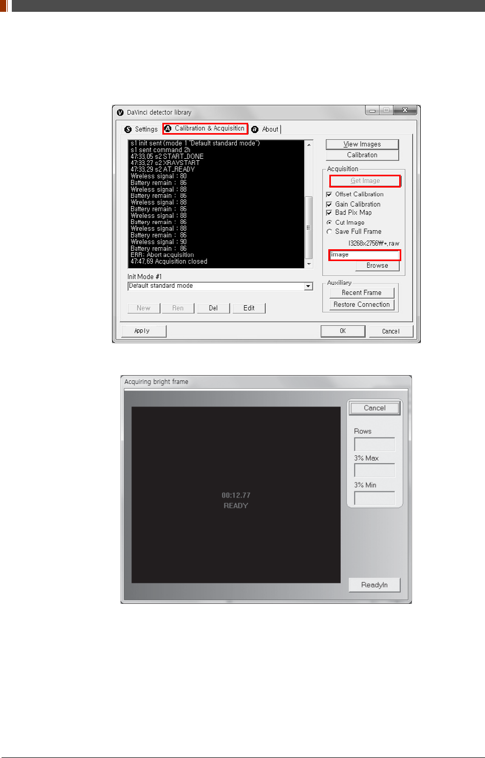
4.2.2 Image Acquisition
1. Click the "Calibration & Acquisition” tab and type the name of the image inside the box
below. After naming the image, click “Get Image”.
2. Shoot an X-ray once the "Acquiring bright frame" window pops up.
3. An acquired image will be stored in “C:\davinci\I.3268x2756 (127type) or 2440x2992
(140type)” and the name of the file will be "(typed name from Step 1).raw”.
4. The format of the stored file is 16 bit little-endian order.
PART I. User & Installation Manual
1417WGC/WCC 103
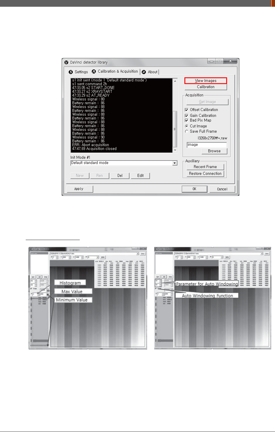
4.3 View Images
1. Click “View Images”
2. Another window will be popped up as below.
Histogram Set Up
PART I. User & Installation Manual
104 1417WGC/WCC
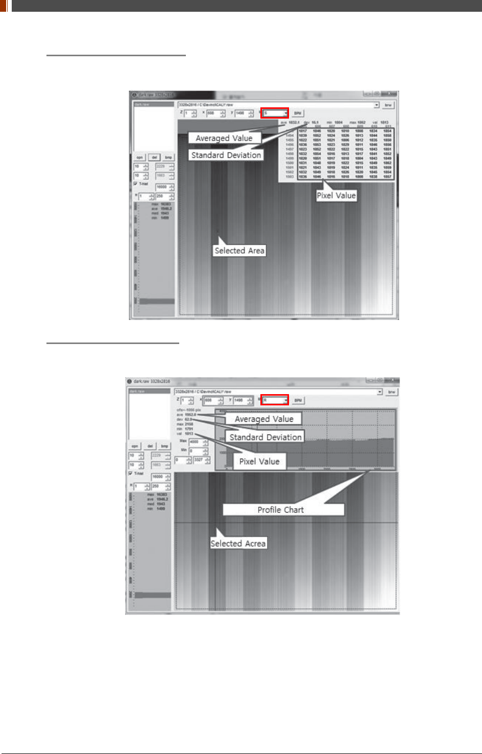
Pixel value at certain level
Choose "S" from marked box.
Profile for horizontal line
Choose "R" from marked box.
PART I. User & Installation Manual
1417WGC/WCC 105
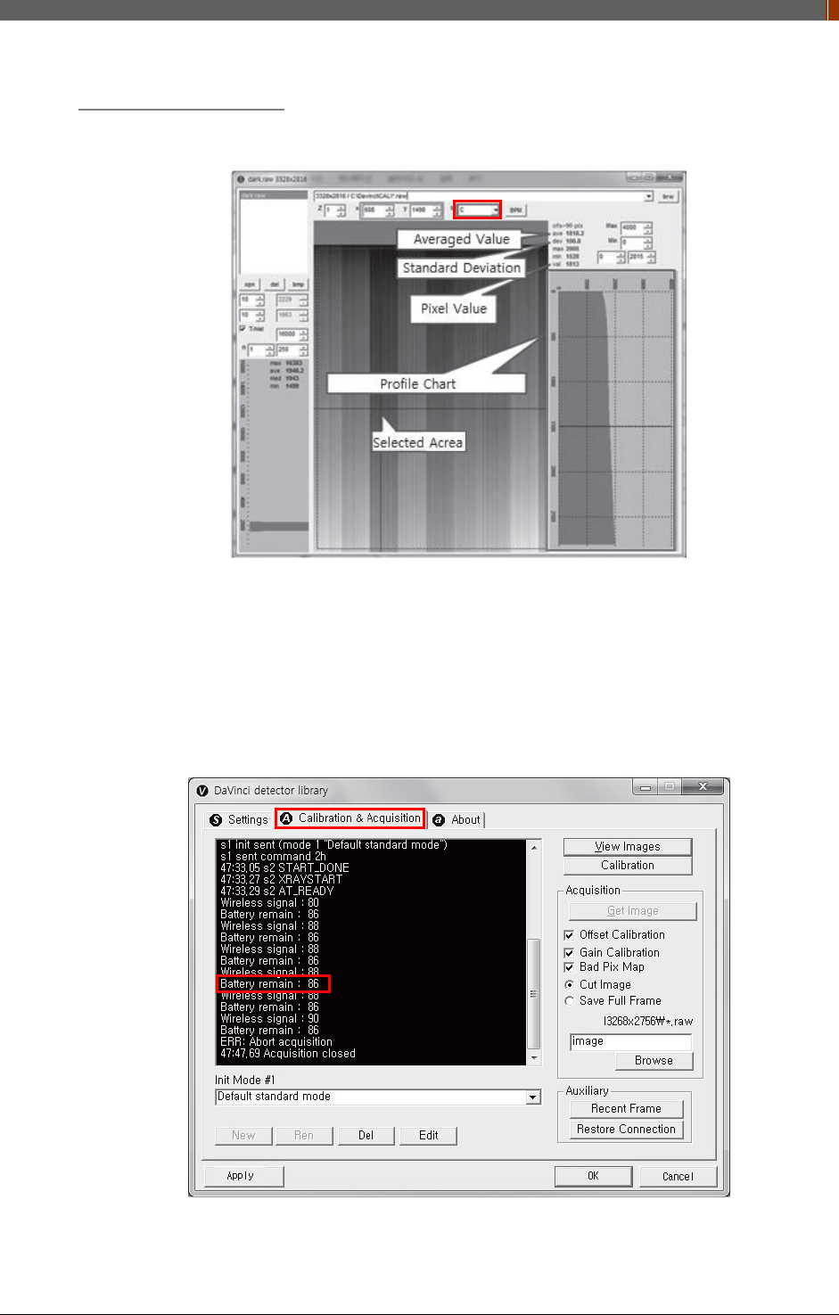
Profile for vertical line
Choose "C" from the marked box.
4.4 Additional Function
4.4.1 Battery Remain
Once you click "Get Image" under the "Calibration & Acquisition” tab, the Status window will
show how much battery remains.
PART I. User & Installation Manual
106 1417WGC/WCC
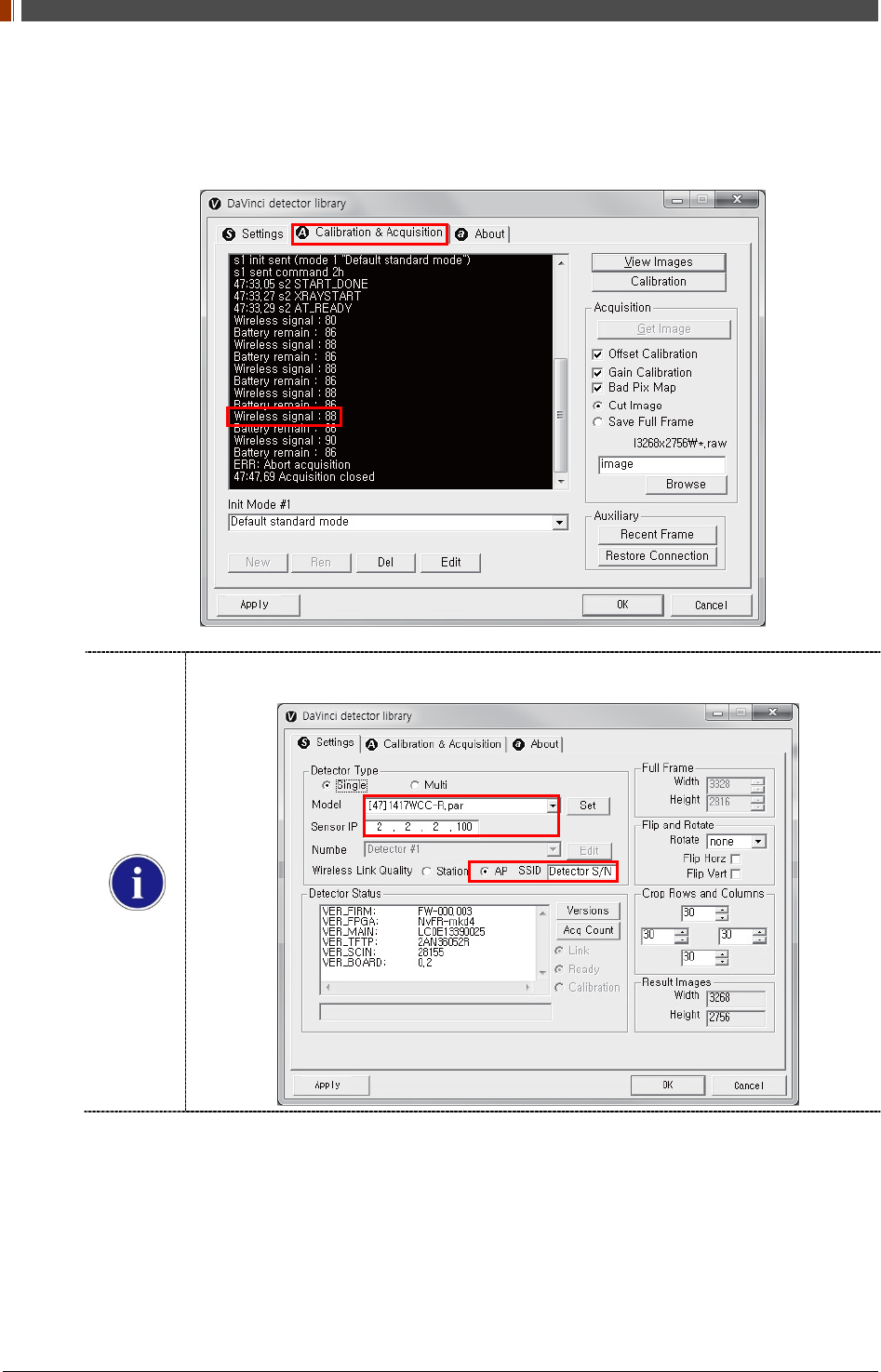
4.4.2 Wireless signal Strength
Once you click "Get Image" under the "Calibration & Acquisition” tab, the Status window will
show the strength of the wireless signal.
Before you check the wireless signal in the AP mode, the detector's serial number should
be entered at the "SSID".
PART I. User & Installation Manual
1417WGC/WCC 107
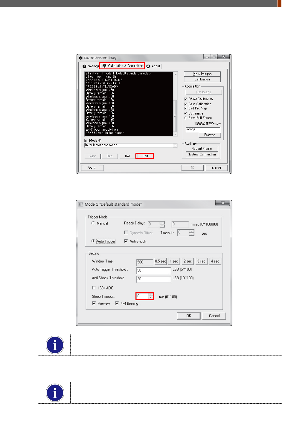
4.4.3 Sleep Mode
1. Click “Edit” under the Calibration & Acquisition tab.
2. Under the “Sleep Timeout” setting, enter a designated time for the detector to go into Sleep
Mode.
Sleep Mode does not apply when set to zero.
Power consumption is reduced by 40% when Sleep Mode is used.
3. To turn off Sleep Mode, attempt to acquire an image or press the power button on the
detector just once.
A normal image can be acquired after 10 seconds Sleep Mode has been turned
off.
PART I. User & Installation Manual
108 1417WGC/WCC
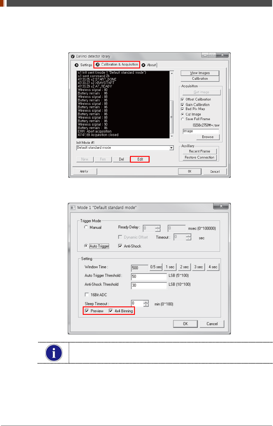
4.4.4 Preview
1. Click “Edit” under the Calibration & Acquisition tab.
2. After checking the Preview and 4x4 Binning, a 4x4 binned image appears which allows for
a quicker image preview.
By unchecking 4x4 Binning, a normal image preview appears.
By unchecking Preview, a full frame image appears.
PART I. User & Installation Manual
1417WGC/WCC 109
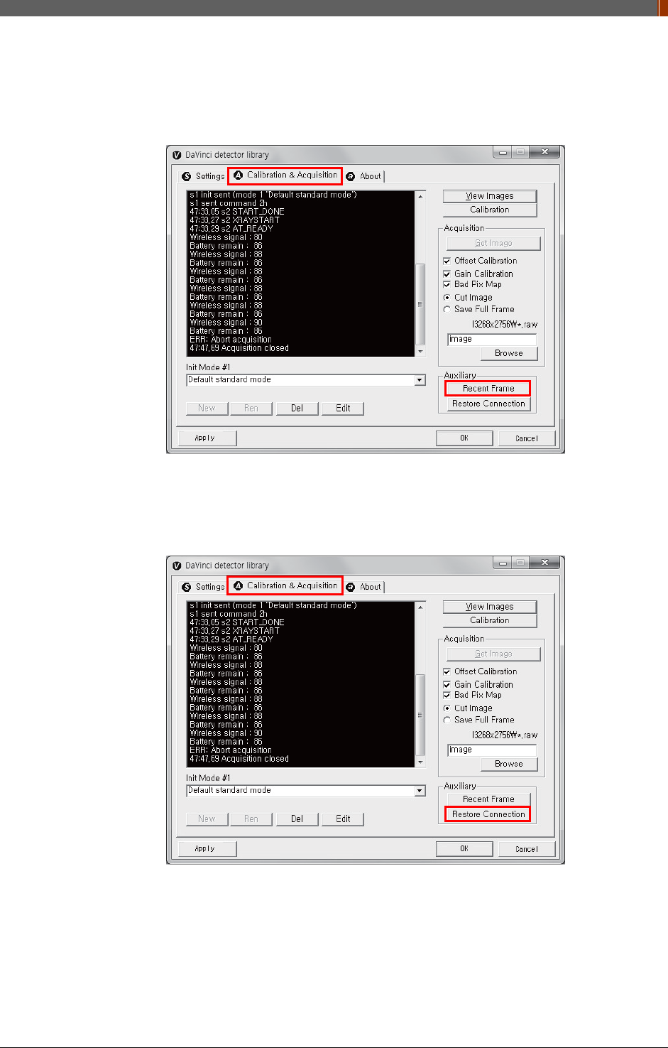
4.4.5 Recent Frame
The last acquired image can be opened by clicking "Recent Frame" under the "Calibration &
Acquisition” tab.
4.4.6 Restore Connection
When the connection between the detector and PC is lost, the connection can be made again
by clicking "Restore Connection" under the "Calibration & Acquisition” tab.
PART I. User & Installation Manual
110 1417WGC/WCC
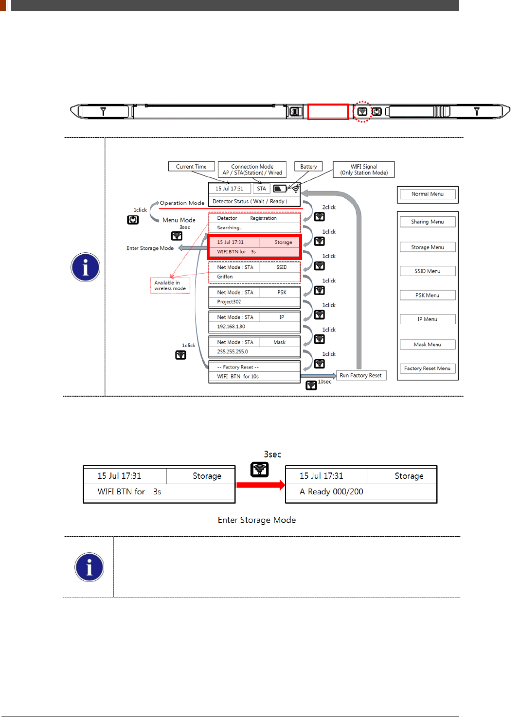
4.4.7 Image Storage function
1. Press the "Mode select button" twice (within 2 seconds) and click one more time to go to
"storage mode".
Mode status can be checked by the OLED window of Detector
2. Press the mode select button for 3 seconds to check the status of storaged images.
When Storage mode is used if the connection between the detector and PC, the
image is stored the memory in the Detector internal
Stored Image can be opened by referring SDK
Image can be stored up to max 200
PART I. User & Installation Manual
1417WGC/WCC 111
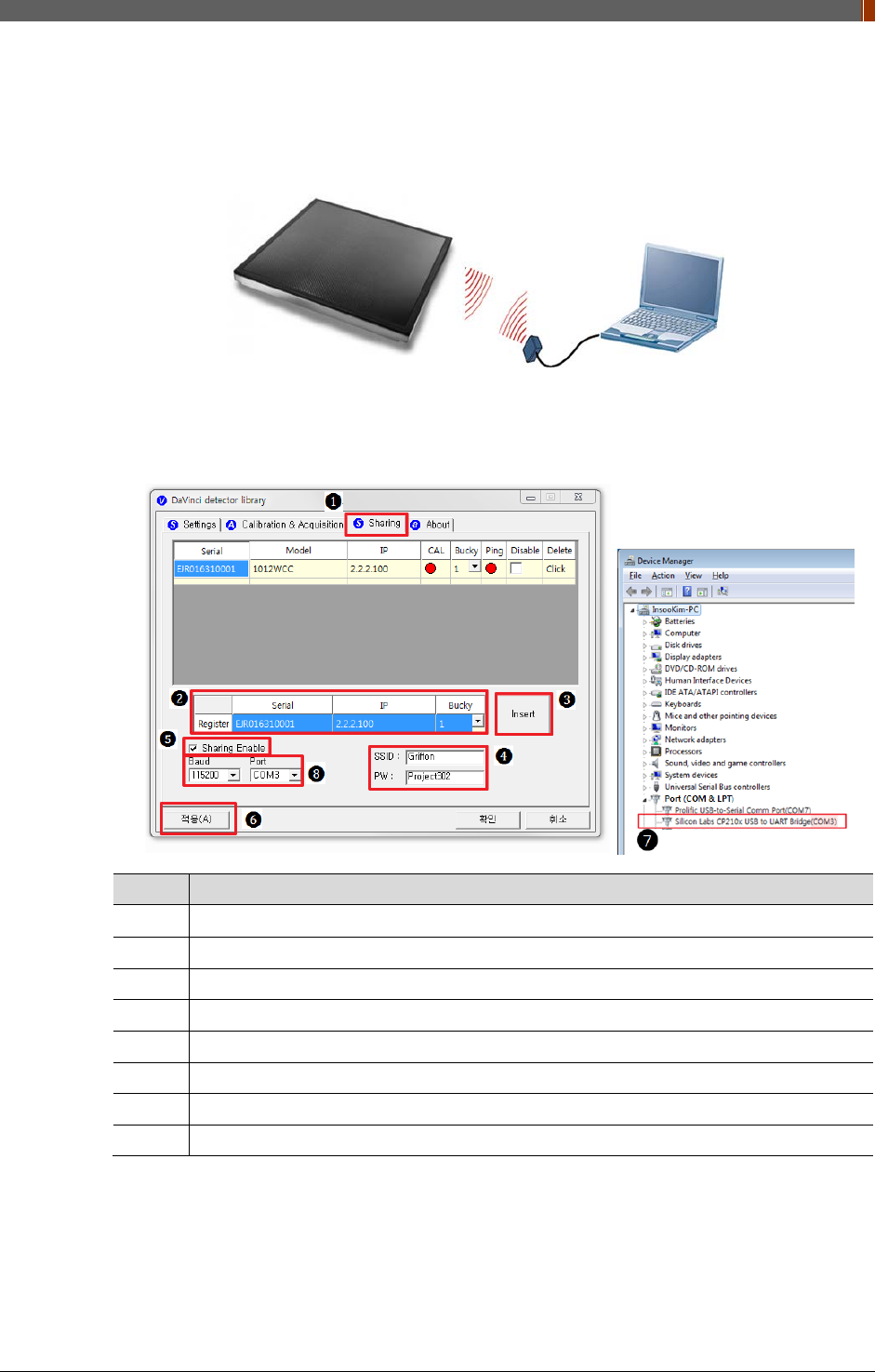
4.4.8 Sharing function
1. Connect the PC and USB IrDA Dongle by using the Micro USB cable.
2. Set vadavas below
No. Overview
❶
Click “sharing” tab
❷
Enter follow thing in order “ serial number, IP, bucky number”
❸
Click “insert”
❹
. Put the SSID and PW of AP
❺
. Check “Enable check box”
❻.
Click “apply” to save
❼
Confirm the connection port in device manager of OS
❽
Baud select 115200 and select confirmed port in device manager
PART I. User & Installation Manual
112 1417WGC/WCC
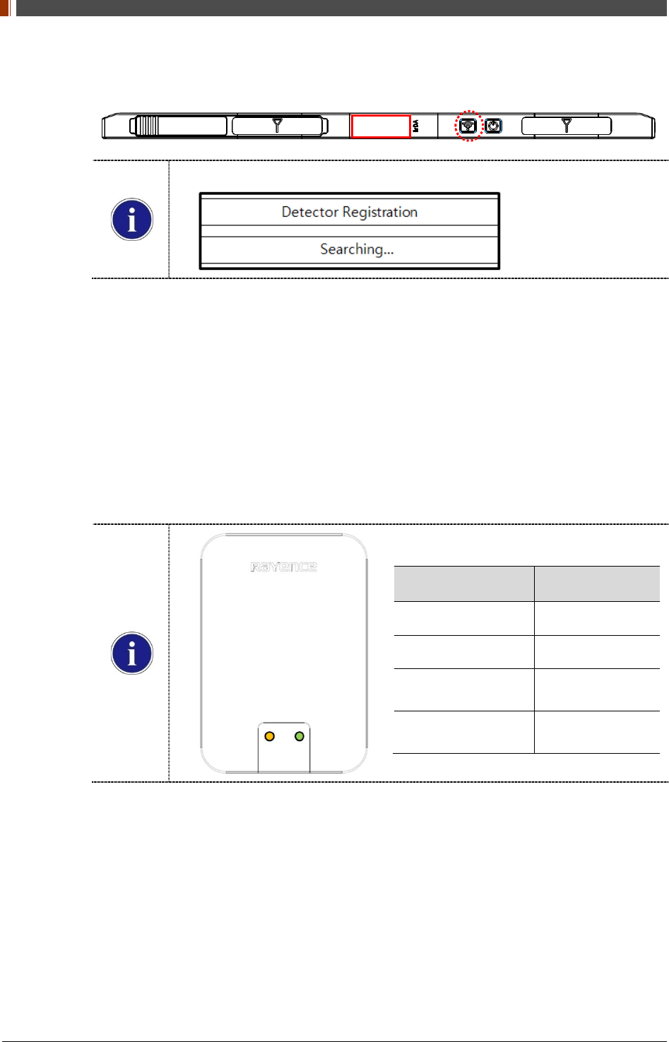
3. Press the "Mode select button" turn on the detector twice (within 2 seconds) and transfer to
"sharing mode".
Mode status can be checked by the OLED window of Detector
4. When approaching the detector with USB IrDA connecting to the PC, transfer the Serial
Number information of detector.
5. Based on the transmitted Serial Number, the CAL folder at the PC is created and the
shooting condition is set then USB IrDA of PC transfers IP/SSID information with Detector.
6. Detector sets the shooting conditions with the IP/ received SSID.
STA Mode: Detector is set by information of wireless router.
AP Mode: PC connects to S/N AP Host name’s wireless router (Detector).
7. If the shooting condition setting is completed, completion status appears at the "OLED
window" and "Sharing mode" is turn off.
IrDA LED Color Status
Green Connected PC
Blinking Orange Transfer the data
End Blinking
Turn on Green Transfer success
End Blinking
Turn off Green Transfer fail
PART I. User & Installation Manual
1417WGC/WCC 113
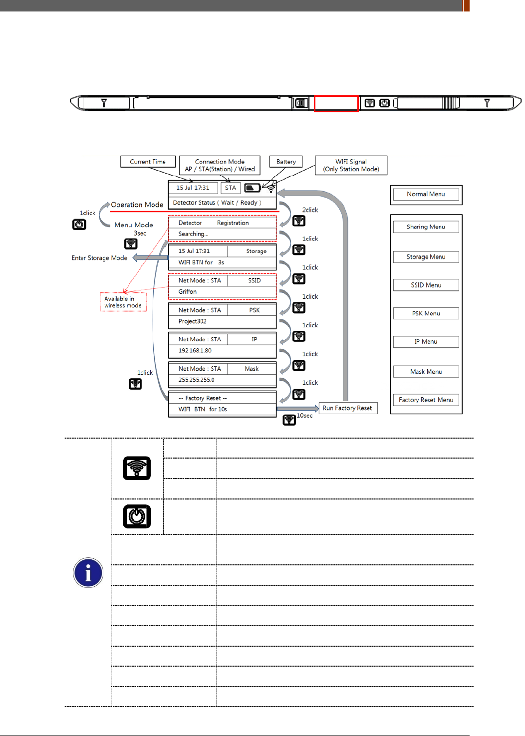
4.4.9 OLED function
8. OLED is operating when detector is turned on.
9. Use the Mode select button and Power button can be used OLED function as follows.
1 click Press the mode select button
2 click Press the mode select button twice (within 2 seconds)
10 sec Press the mode select button for 10 seconds
1 click Press the power button
Normal menu - Will Show the (Time / Battery remain / Wireless signal) of
detector
Sharing menu - Operation the “sharing function”
Storage menu - Operation the “storage function”
SSID menu - Will Show the SSID information of detector
PSK menu - Will Show the PSK information of detector
IP Menu - Will Show the IP information of detector
Mask menu - Will Show the Mask information of detector
Factory reset menu - Factory reset menu

PART I. User & Installation Manual
114 1417WGC/WCC
5. Maintenance
5.1 Cleaning
1. Clean the detector with IPA (Isopropyl-alcohol) when it is contaminated.
2. Before cleaning the detector, turn off the power and separate the battery.
3. Wear waterproof gloves to protect your hands from direct contact with IPA or any other
liquid.
4. Do not pour or spray IPA directly on the detector. Use fabric or soft cloth moistened with IPA
to clean.
5. Avoid getting IPA or any other liquid into the detector.
6. After cleaning, wait until the IPA is dried completely.
5.2 Inspection
1. In order to ensure that the detector is used safely and normally, please be sure to inspect
the product regularly before use. If any problem occurs, please contact Rayence Customer
Service team.
2. Please perform inspections based on the check list below.
Inspection List
U
s
e
r
Vendor Cycle
Check if cables are not
damaged o
Daily
Check if plugs and connectors
are not loose or damaged o
Daily
Check if cover or part is not
damaged o
Daily
Check the LED indicator o
Daily
Re-Calibration o Half Year
Check the performance of the
product by doing test shots
with Phantom or resolution
chart
o
Yearly
PART I. User & Installation Manual
1417WGC/WCC 115
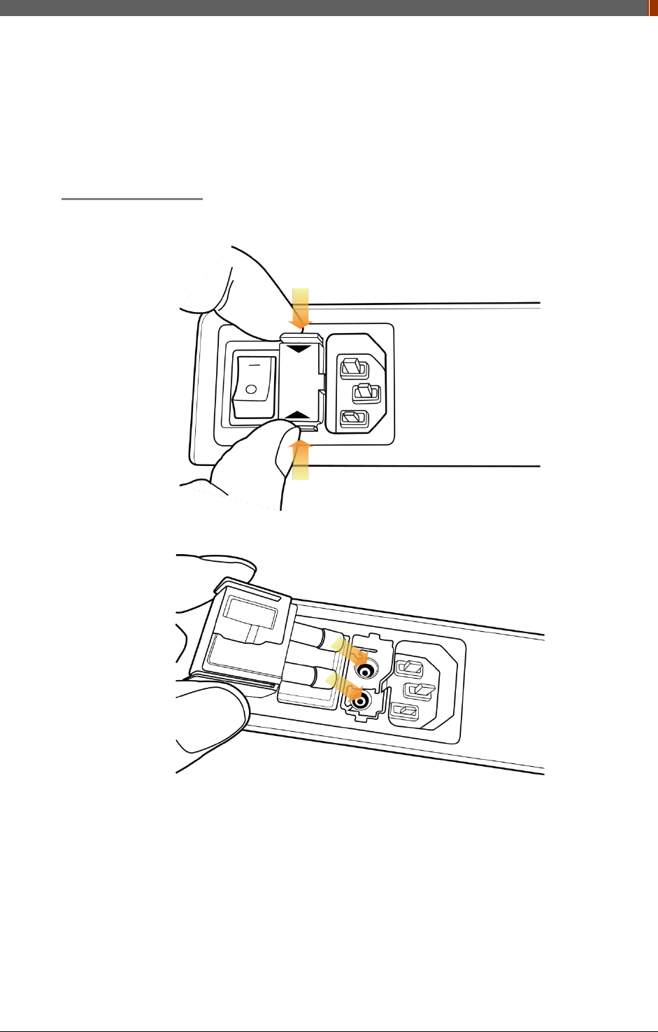
5.3 Replaceable Parts and Instruction of Replacement
5.3.1 Fuse: T3.15 AL 250V
Replacing the Fuse
1. Press the fuse as below and pull the fuse box.
2. Pull the fuse and replace with another fuse.
5.3.2 Power cord: H05VV-F 0.75SQ * 3C
5.3.3 Ethernet Cable: UTP 4PR 24AWG (CAT.6, straight-through)

PART I. User & Installation Manual
116 1417WGC/WCC
5.4 Disposal or Recycling
Follow local governing ordinances and recycling plans regarding the disposal or recycling of
device components.
Disposal of old Electrical & Electronic Equipment
(Application in the European Union and other European countries with separate
collection system.) This symbol indicates that this product shall not be treated as
household waste. Instead, it shall be handed over to the applicable collection point
for the recycling of electrical and electronic equipment. By ensuring this product is disposed of
correctly, you will help prevent potential negative consequences for the environment and human
health, which could otherwise be caused by inappropriate waste handling of this product. For
more detailed information about recycling this product, please refer to local governing
ordinances and recycling plans.

PART I. User & Installation Manual
1417WGC/WCC 117
6. Warranty
6.1 Warranty
If Buyer promptly notifies RAYENCE or Seller regarding any parts that fail to perform as
specified under normal usage during the Warranty Period and RAYENCE determines that such
failure resulted from a defect in materials or workmanship during the Warranty Period, then
RAYENCE, at its option, shall repair, rebuild or adjust the affected parts.
RAYENCE shall have no obligation for any defects to the extent that such defect arises out of (i)
normal and fair wear and tear or Product which has been modified without RAYENCE's
approval, (ii) Product which has not been installed in strict conformity to the RAYENCE's
directions or which have been subjected to electrical or other abuse, or damaged by improper
handling, storage or use by Buyer or a third party, (iii) use of Product in combination with
devices or products not purchased from RAYENCE; (iv) use or application of Product in a field
or in an environment for which such Product was not designed or contemplated; (v) use of any
parts or material not provided by RAYENCE for warranty service; or (vi) the third party’s
maintenance not certified by RAYENCE; or (vii) force majeure such as natural disaster.
The remedies contained in this warranty are Buyer’s exclusive remedies. RAYENCE shall not,
in any event or under any circumstances, be responsible for damages or other sums in excess
of the total purchase price actually paid by Buyer to Seller i.e., RAYENCE or RAYENCE’s
authorized agent. Without limiting the generality of the foregoing under no circumstance shall
RAYENCE be responsible or liable in any regard with respect to damages from loss of use, loss
of time, loss of data, inconvenience, commercial loss, lost profits or savings, or other incidental,
special or consequential damages claimed by Buyer to arise out of the use or inability to use the
Product, even if Buyer has been advised of the possibility of such damages.
In the event that the product is returned to RAYENCE after the warranty has expired, RAYENCE
reserves the right to invoice a reasonable fee for the repair services provided to Buyer.
RAYENCE shall make the sole final determination about whether the fail to perform occurred in
normal usage (under warranty) or not (excluded from warranty). If the authorized agent or the
Buyer doesn’t accept the result of RAYENCE’s investigation, the burden of proof is on them.
Warranty Procedure
If Buyer needs to make a claim based on this Warranty, Buyer should advise Seller in writing
immediately at the following address:
RAYENCE Co., Ltd.
14, Samsung 1-ro 1-gil, Hwaseong-si, Gyeonggi-do, Korea
Tel: +82-31-8015-6245
Fax: +82-31-8015-6300
E-mail: marketing@rayence.com
www.rayence.com

PART I. User & Installation Manual
118 1417WGC/WCC


PART II. Service Manual
1417WGC/WCC 120
1. Overview
This service manual gives additional instructions for setting up the detector.
PART II. Service Manual
1417WGC/WCC 121
2. FPD Manager Instruction (IP, SSID Set Up / Firmware, FPGA Update)
2.1 Detector IP Address Set Up
1. Turn on the power of detector and connect with PC. (IP address: 2.2.2.100)
[Connect as wired mode (IP address: 2.2.2.101) with Link cable or wireless mode (IP
address: 2.2.2.100).]
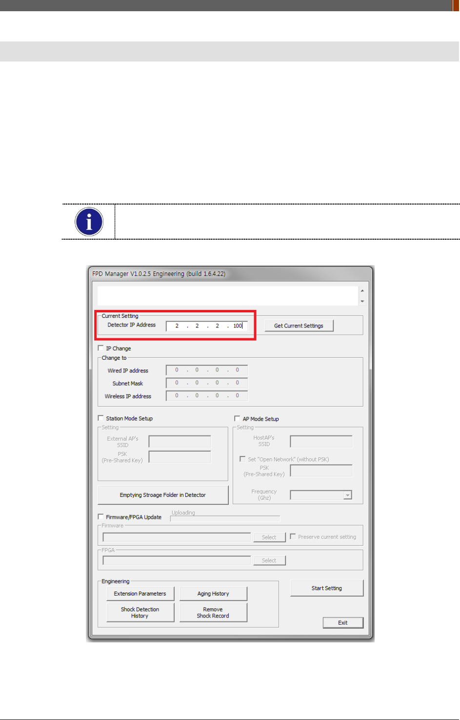
2. After the power of detector is on, open "FPD_Manager.exe".
3. Type detector's current IP address at "Detector IP Address" from "Current Setting" as below.
Detector's Ethernet Controller is operated with Second IP address,
192.168.124.80.
PART II. Service Manual
1417WGC/WCC 122
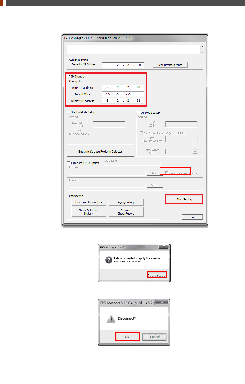
4. Select "IP change" and type the IP address. Click "Start Setting".
5. Click "OK" once the message below pops up.
6. Click "OK" again once the message below pops up.
7. Turn off the power of the detector and after 5 seconds, turn the power back on.
PART II. Service Manual
1417WGC/WCC 123
2.2 SSID, PSK (Pre-Shared Key) Set Up
1. Turn on the power of the detector and connect it to the PC. (IP address: 2.2.2.100)
[Connect as wired mode (IP address: 2.2.2.101) with Link cable or wireless mode (IP
address: 2.2.2.100).]
2. After the power of detector is on, open "FPD_Manager.exe".
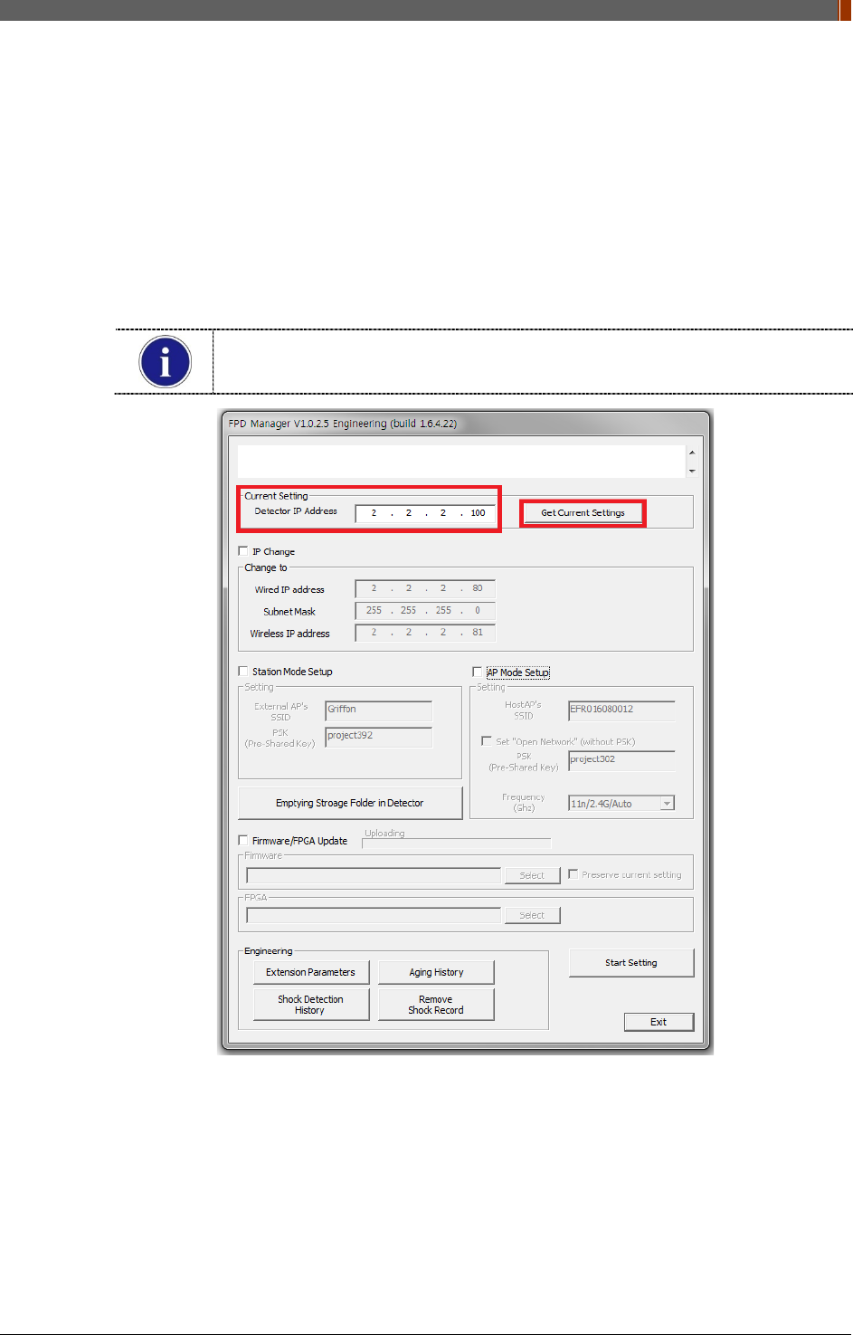
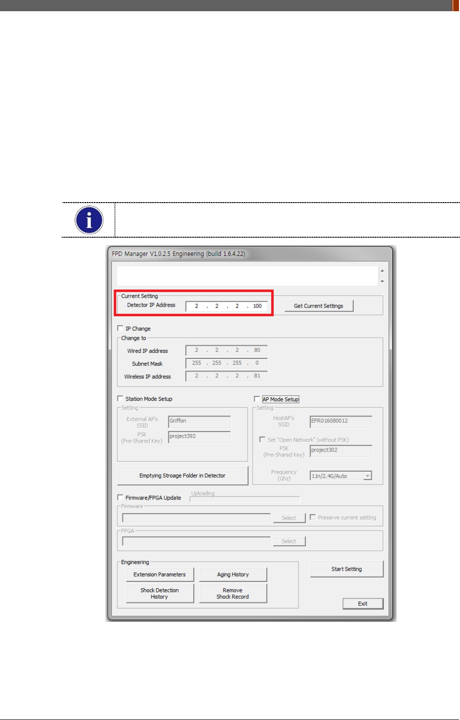
3. Type the detector's current IP address in "Detector IP Address" from "Current Setting" as
below.
Detector's Ethernet Controller is operated with Second IP address,
192.168.124.80.
4. Current SSID and PSK (Pre-Shared Key) is displayed once the "Get Current Settings"
button is pressed.
PART II. Service Manual
1417WGC/WCC 124
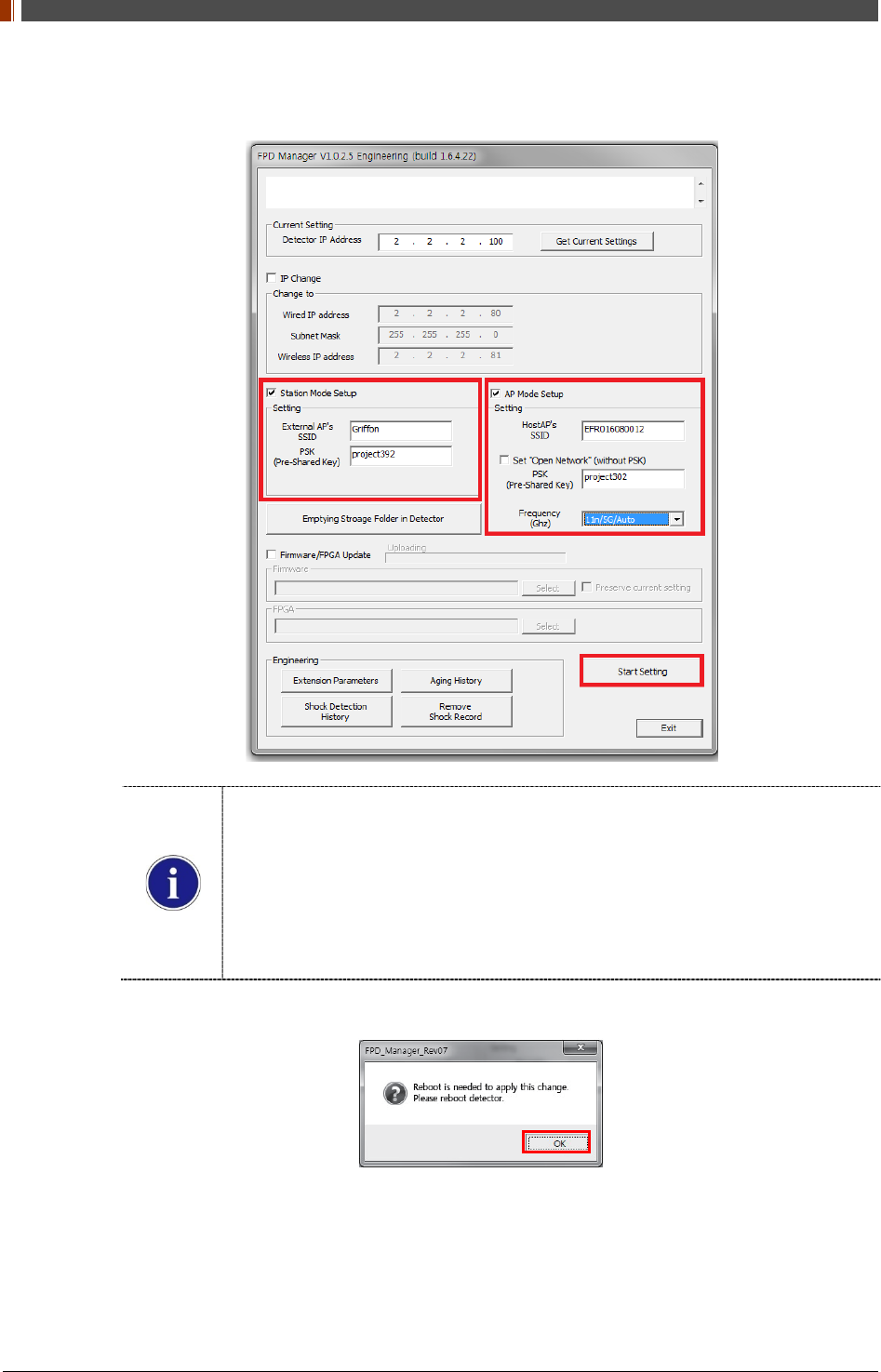
5. Select "Station Mode Setup" and "AP Mode Setup". Type the SSID and PSK, and click
"Start Setting".
Station Mode Setup: When external AP is being used, use the same SSID and
PSK as applied.
AP Mode Setup: When built-in AP is being used, use the same SSID and PSK as
applied.
Frequency (Ghz): Default Channel is set to 11n/2.4G/Auto. (802.11n/2.4Ghz/ACS).
The ACS (Automatic Channel Selection) feature is setting automatically channel
for good AP Mode connection quality. If the Channel causes conflict, the channel
can be changed through this program.
6. Click "OK" once the message below pops up.
7. Turn off the power of detector and after 5 seconds, turn the power back on.
PART II. Service Manual
1417WGC/WCC 125
2.3 Firmware, FPGA Update
1. Turn on the power of the detector and connect it to the PC.
[Connect as wired mode (IP address: 2.2.2.101) with Link cable or wireless mode (IP
address: 2.2.2.100).]
2. After the power of detector is on, open "FPD_Manager.exe".
3. Type the detector's current IP address in "Detector IP Address" from "Current Setting" as
below.
Detector's Ethernet Controller is operated with Second IP address,
192.168.124.80.
PART II. Service Manual
1417WGC/WCC 126
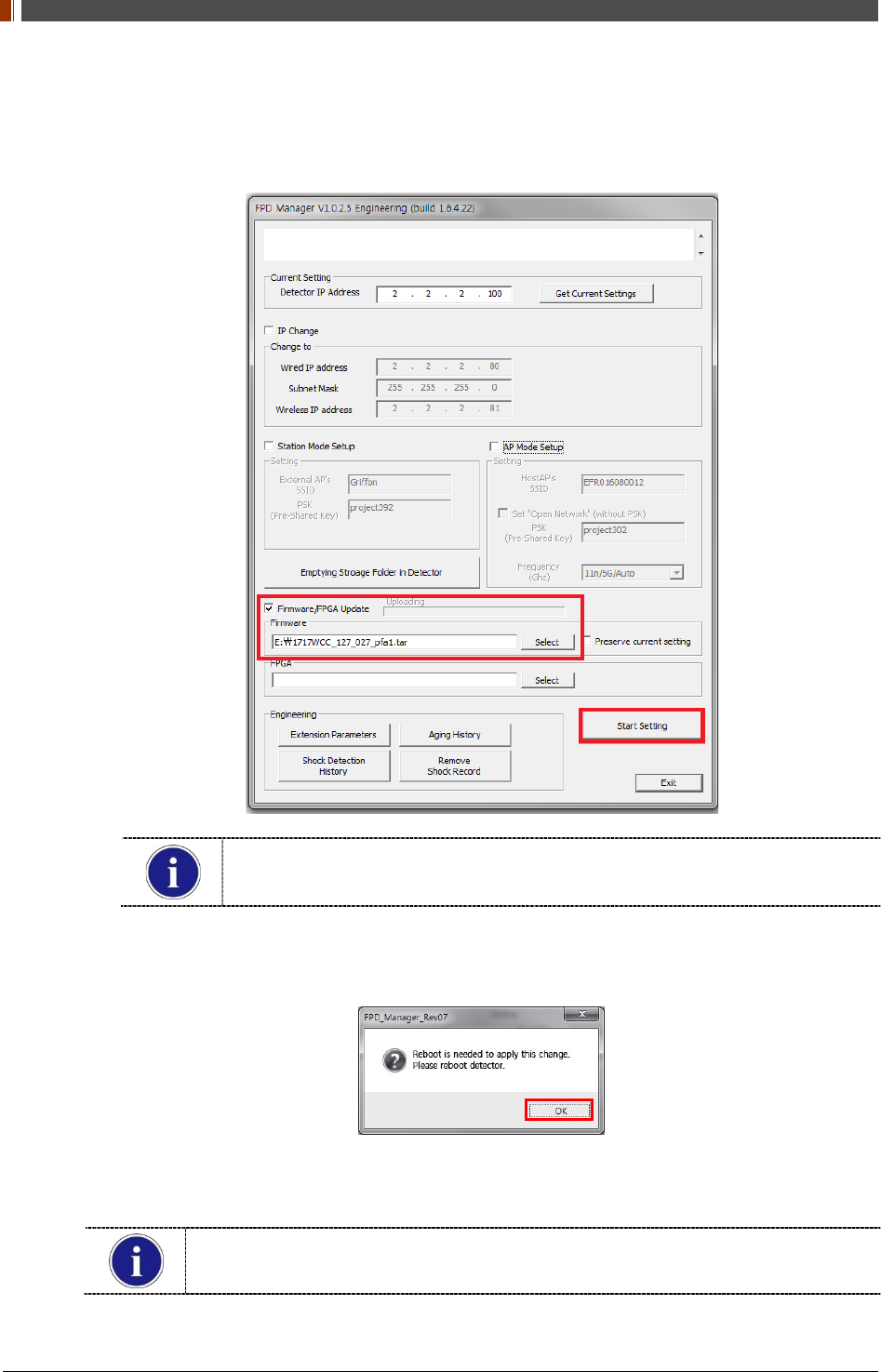
4. Select "Firmware/FPGA Update" and click "Select" to browse the Firmware and FPGA.
Once the files are selected, click "Start Setting".
Firmware File: File extension is either Davinci or tar.
FPGA file: File extension is bin.
5. Click "OK" once the message below pops up.
6. Turn off the power of detector and after 5 seconds, turn the power back on.
Detector IP address might be changed to 192.168.1.80 after updating depends on
Firmware.
PART II. Service Manual
1417WGC/WCC 127
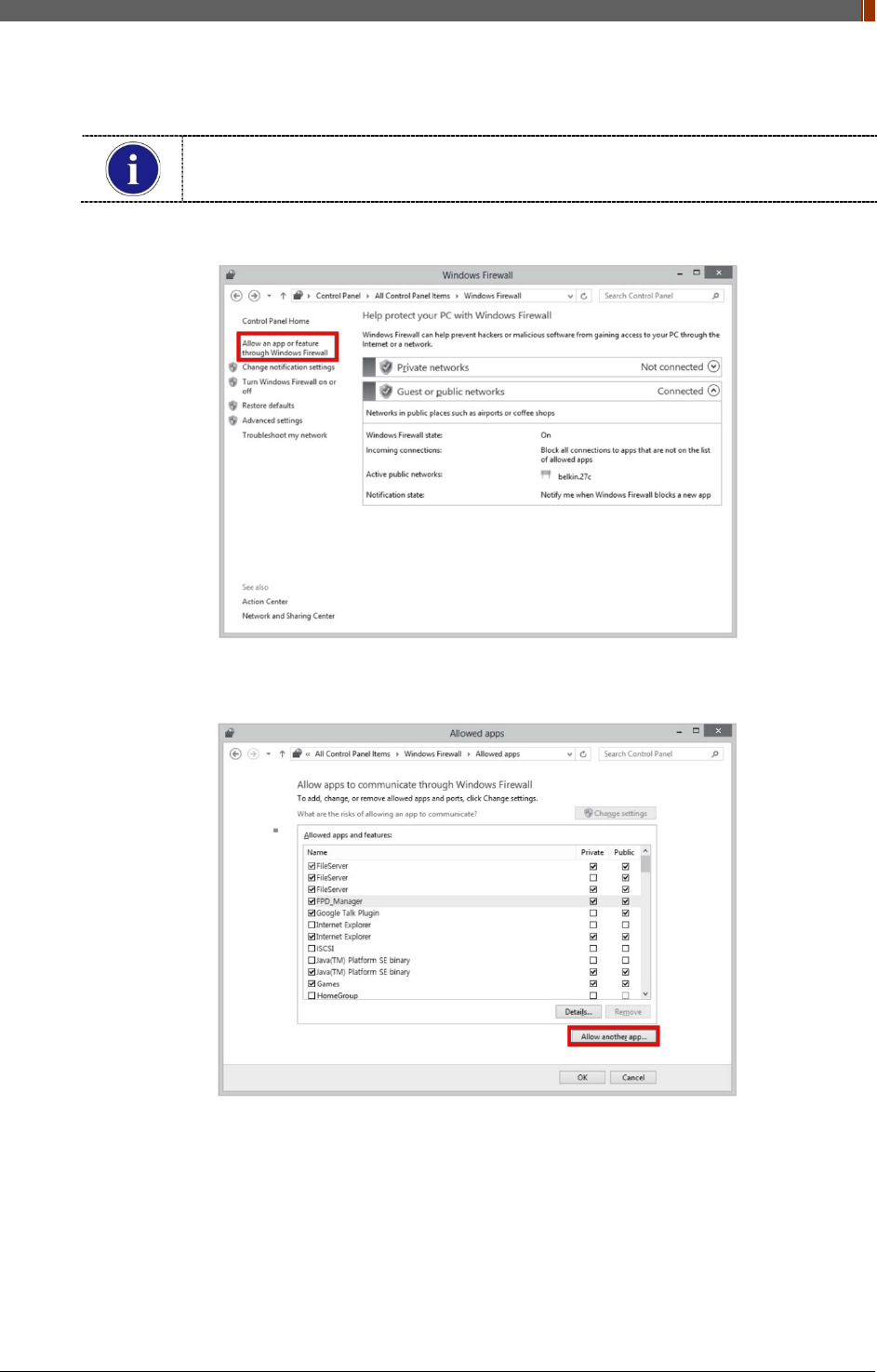
2.4 Set Windows Firewall to use FPD_Manager (For Win 7)
FPD_Manager would not be performed properly if Windows Firewall blocks
FPD_Manager. Please follow the steps below in this case.
1. ‘Control Panel’ -> ‘Windows Firewall’ -> ‘Allow an app or feature through Windows Firewall’
2. Check "Name", "Private" and "Public" if FPD_Manager program is already on the list. Click
"Allow another app..." when FPD_Manager program is not on the list.
PART II. Service Manual
1417WGC/WCC 128
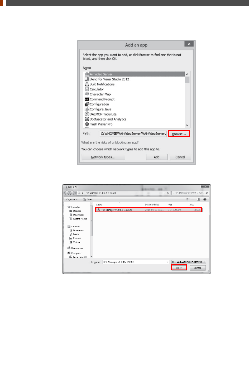
3. Select the program and add if it is already on the list. Click "Browse" when the program is
noon the list.
4. Browse and open FPD_Manager program and repeat step ②.
PART II. Service Manual
1417WGC/WCC 129
3. Multi Detector Set Up
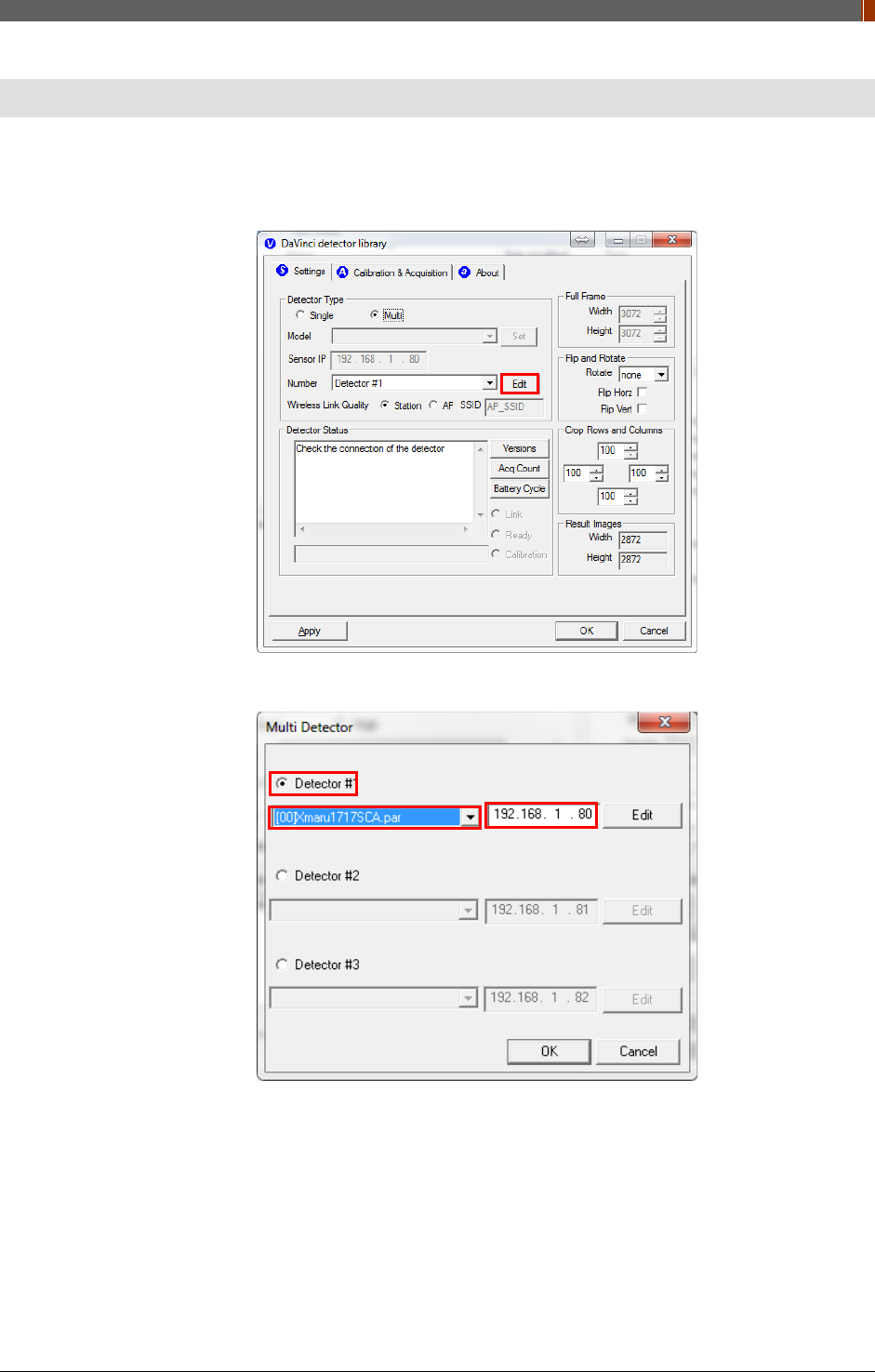
1. Open “_vadav.lnk” from "C:\davinci”.
2. Click "Edit" under the "Settings" tab.
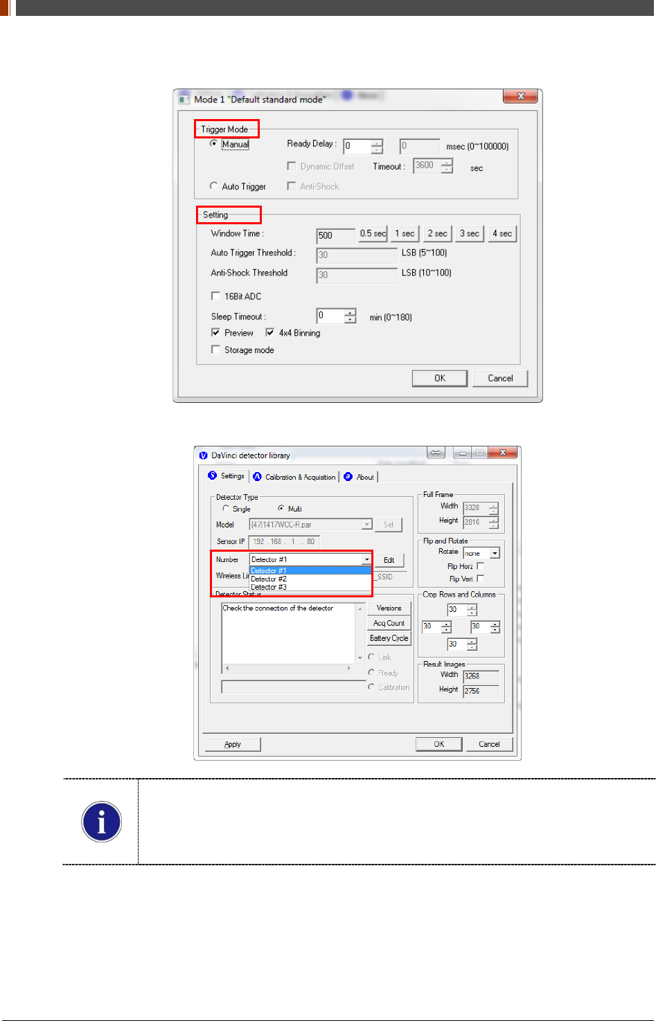
3. Select "Detector #1". Choose the product model and type the IP address.
PART II. Service Manual
1417WGC/WCC 130
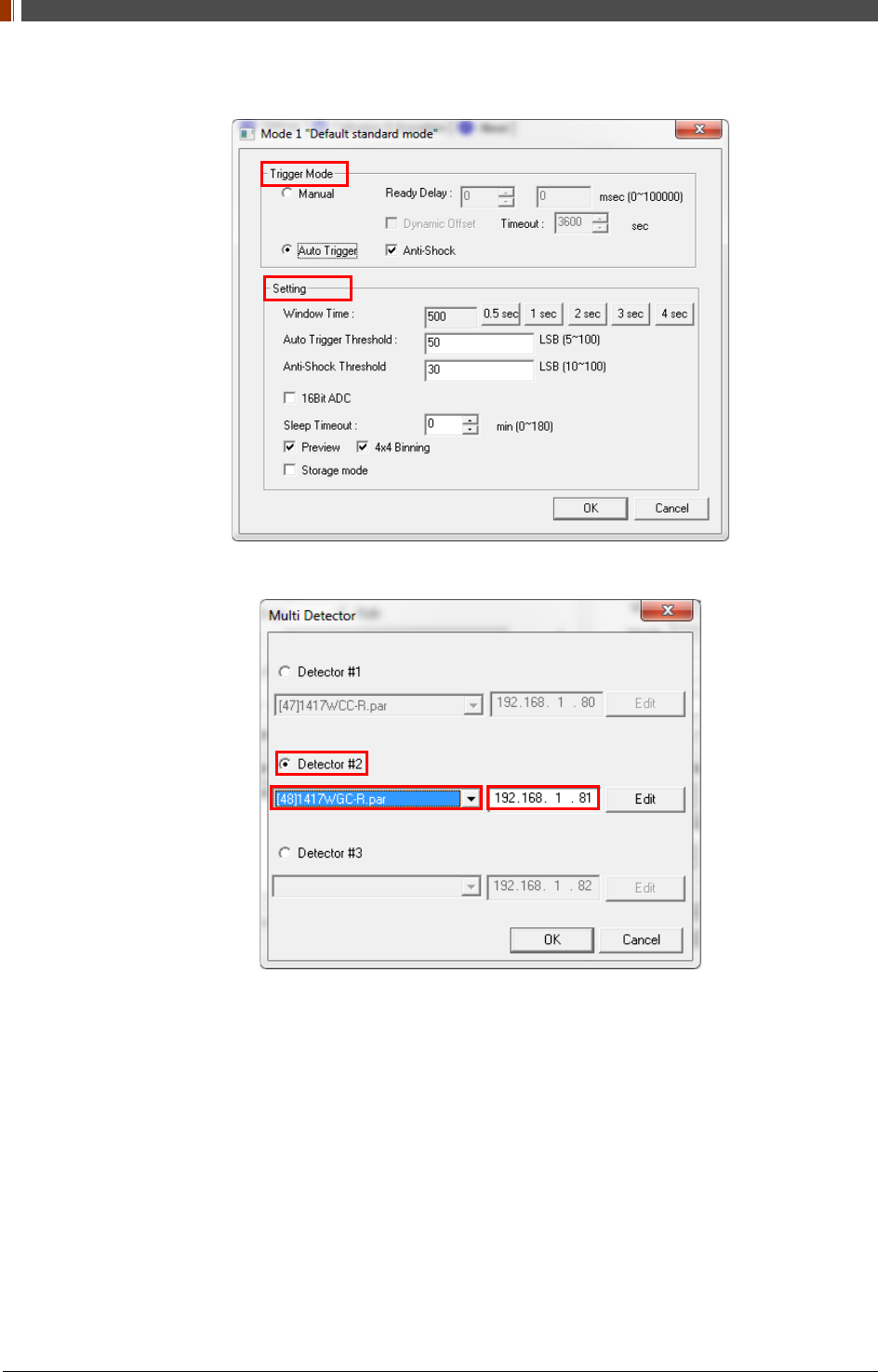
4. Click "Edit" from "Detector #1". Set up the "Trigger Mode" and "Setting".
5. Select "Detector #2". Choose the product model and type the IP address.
PART II. Service Manual
1417WGC/WCC 131
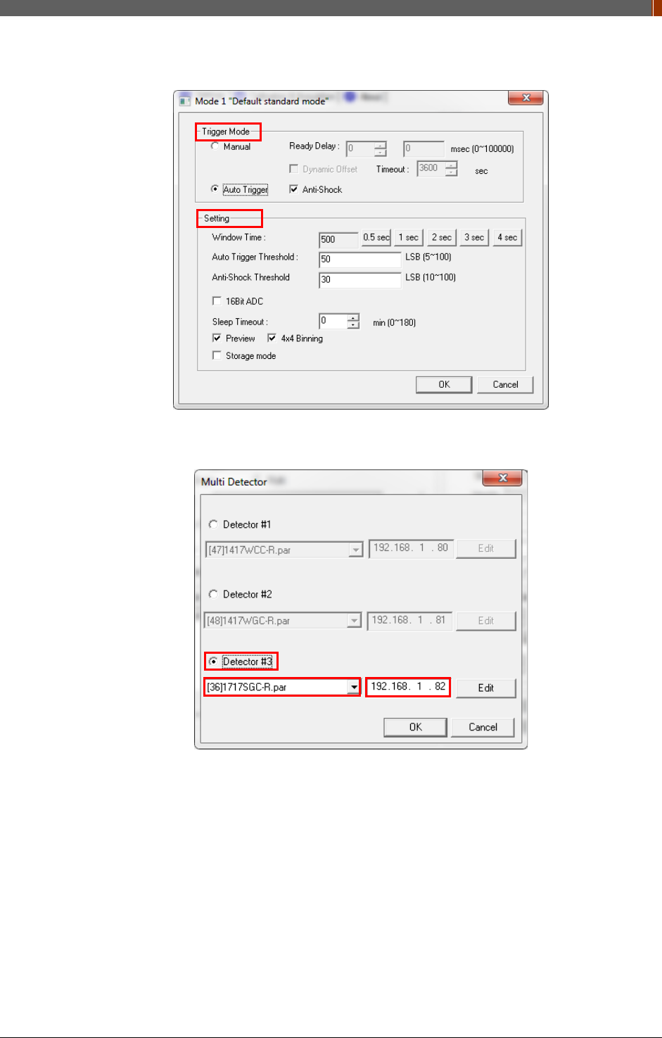
6. Click "Edit" from "Detector #2". Set up the "Trigger Mode" and "Setting".
7. If a third detector is being used, select "Detector #3". Choose the product model and type
the IP address.
PART II. Service Manual
1417WGC/WCC 132
8. Click "Edit" from "Detector #3". Set up the "Trigger Mode" and "Setting".
9. Choose the detector from the "Number" option and perform the calibration.
The calibration folder is named according to the third and fourth numbers of the IP
address. (e.g. C:\Davinci\CAL_01_80)
For further instructions on calibration, please refer to 0
Calibration in Part.1 User & Installation Manual.

PART II. Service Manual
1417WGC/WCC 133
4. Troubleshooting
If any problem occurs during the usage of the product, please use this chapter as a trouble
shooting guide.
Follow the instructions to resolve the problem. If the problem is not resolved, please contact our
Rayence Customer Service team (E-mail: marketing@rayence.com).
4.1 LAN Connection Issue
1. Wireless Mode
1. Check the power
Make sure the remaining battery percentage is above 25%.
Check that the power of the detector is on.
2. Check the AP (Access Point) IP setting
Make sure the AP (Access Point) is set up as recommended.
SSID: Griffon
Internal network
• IP address: 2.2.2.1
• Subnet mask: 255.255.255.0
• Dynamic IP allocation range: 2.2.2.2 ~ 2.2.2.254
Pre-Shared Key(PSK): project302
• Authentication methods: WPAPSK or WPA2PSK
• Password methods: TKIP/AES
Channel (Frequency)
• Avoid the crowded channel option.
• Use the "Auto-Channel selection" function if the external AP has the feature.
PART II. Service Manual
1417WGC/WCC 134
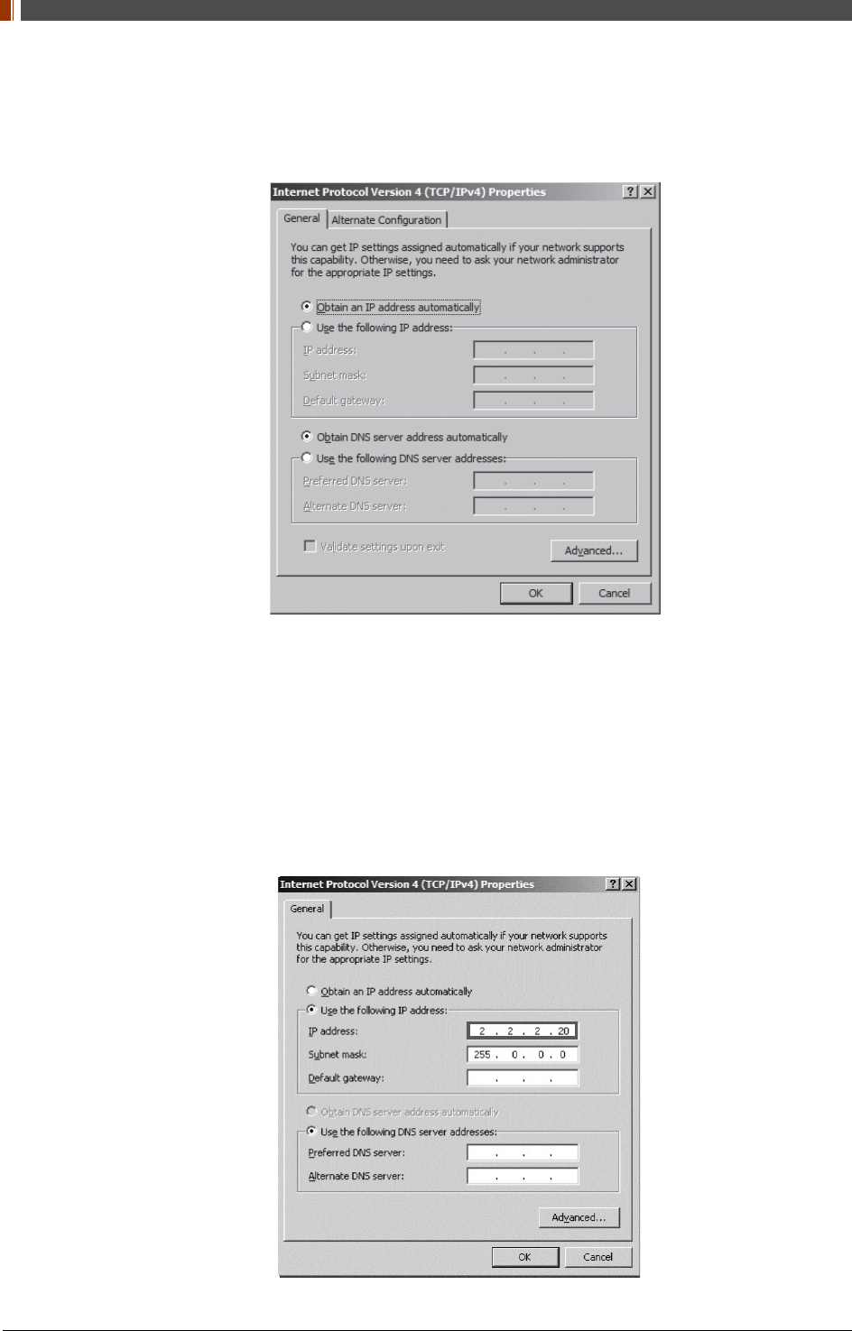
3. Check PC Set up
Make sure that the "Obtain an IP address automatically" is selected from "Internet Protocol
Version 4 (TCP/IPv4)".
2. Wired Mode
1. Check the power
Check the link cable and the power cord are connected properly
Check that the power of the detector is on.
2. Check PC Set up
Make sure that the IP address is set to”2.2.2.20” from "Internet Protocol Version4 (TCP/IPv4)"

PART II. Service Manual
1417WGC/WCC 135
4.2 Lost IP Address (Use one of the methods below)
1. Use a second IP address (192.168.124.80) and change the IP address
2. Press the “Reset” button to reset the IP address. (Default IP : 2.2.2.100)
PART II. Service Manual
1417WGC/WCC 136
4.3 Auto Trigger Mode
Follow these instructions when the panel auto triggers on its own and/or unintentionally acquires
blank images.
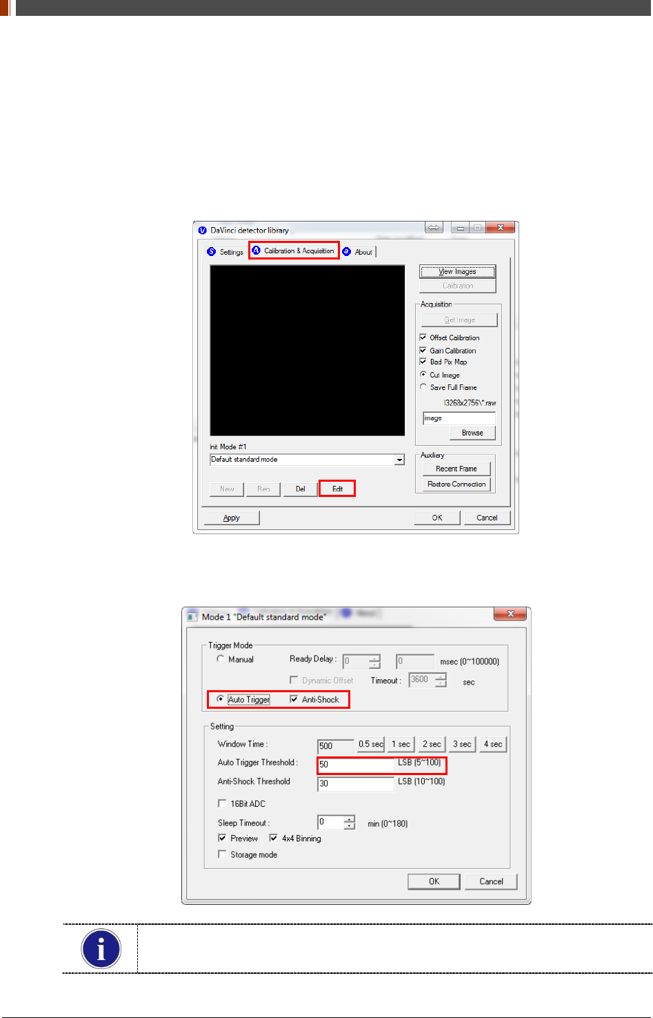
1. Open “_vadav.lnk” from "C:\davinci”.
2. Click the "Calibration & Acquisition" tab.
3. Click "Edit".
4. Change "Auto Trigger Threshold" from 5 to 100 and click "OK".
The Auto Trigger Threshold default value are 50 for CsI models and 30 for GdOS
models
PART II. Service Manual
1417WGC/WCC 137
Supplement.1 Wireless AP Set Up Instruction
(WAP Model: ASUS RT-AC66U)
1. Connect the LAN cable from the Ethernet port #1 on the PC to the
Ethernet port #1 on the AP.
2. Access AP Set Up Page
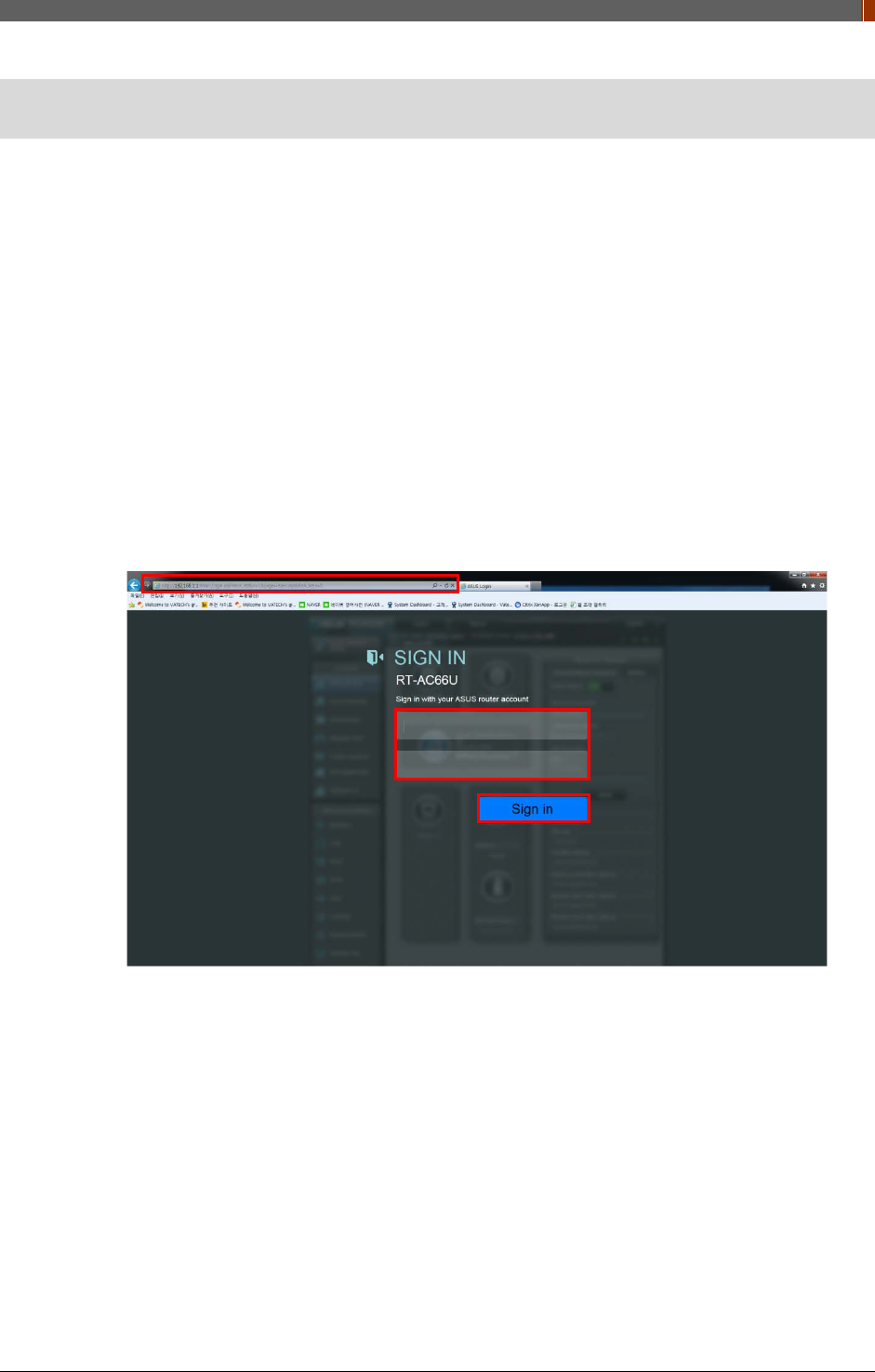
1. Open a web browser. Once type 192.168.1.1. In the browser address bar a login window
appears.
2. Enter the ID and password.
3. Click "Ok".
[ID: admin | PW: admin]
IP address for the first access is 192.168.1.1.
After changing the IP address to 2.2.2.1, use IP address 2.2.2.1 for accessing.
①
②
③
PART II. Service Manual
1417WGC/WCC 138
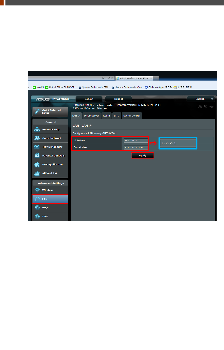
3. Click the "Setup" tab, and then click the "Basic Setup" page.
1. Type 2.2.2.1 at "IP Address".
2. Type 255.255.255.0 at "Subnet Mask".
3. Click "Apply".
PART II. Service Manual
1417WGC/WCC 139
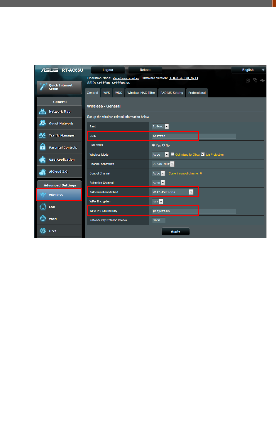
4. Click the "Wireless" tab, and then click the "Basic Wireless Settings" page.
Set up Wireless Settings as below.
(SSID: Griffon, WPA2-Personal, Pre-Shared Key: project302)
1417WGC/WCC 140
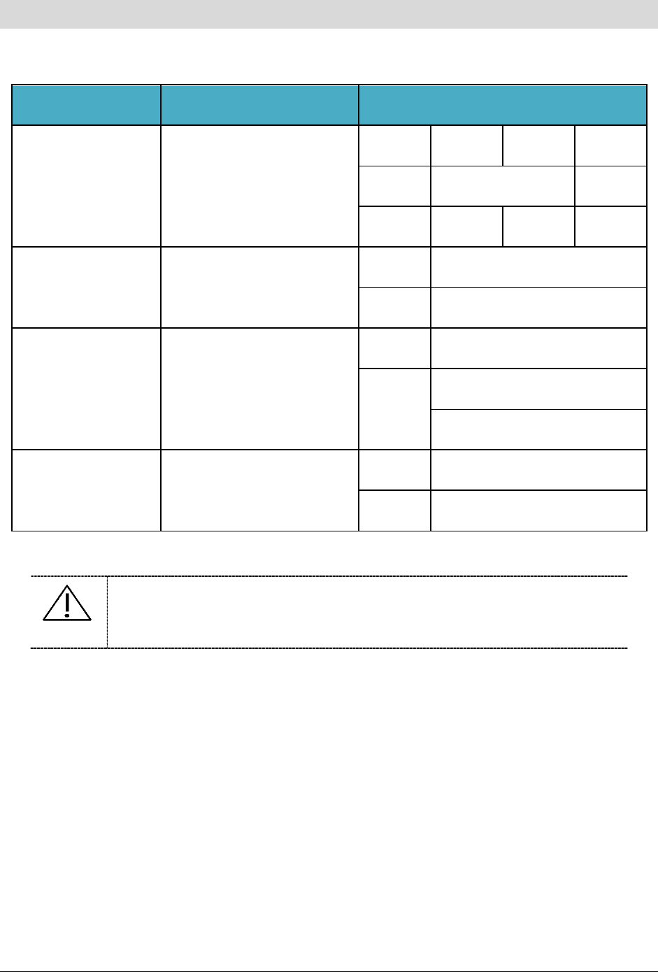
Supplement.2 Recommended Generator Specification
Model Manufacture Specification
CMP 200 Communications & Power
Industries
32kW 40kW 50kW
kVp 40-125 40-150
mA 10-400 10-500 10-630
EDITOR HFe 501 Rontgenwerk Bochum
kVp 40-150
mA 10-630
UD150L-40E/40F Shimadzu
kVp 40-150
mA
@100 kVp- 500(320)
@80 kVp- 630(400)
PXR-321B Poskom Co.,Ltd.
kVp 125/150
mA 500
CAUTION
To our best knowledge, the detector is compatible with the X-ray generators with
the specifications described above. If you have questions regarding the
compatibility issue for other generators which are not listed above, please
contact your Rayence representative.
PART II. Service Manual
1417WGC/WCC 141
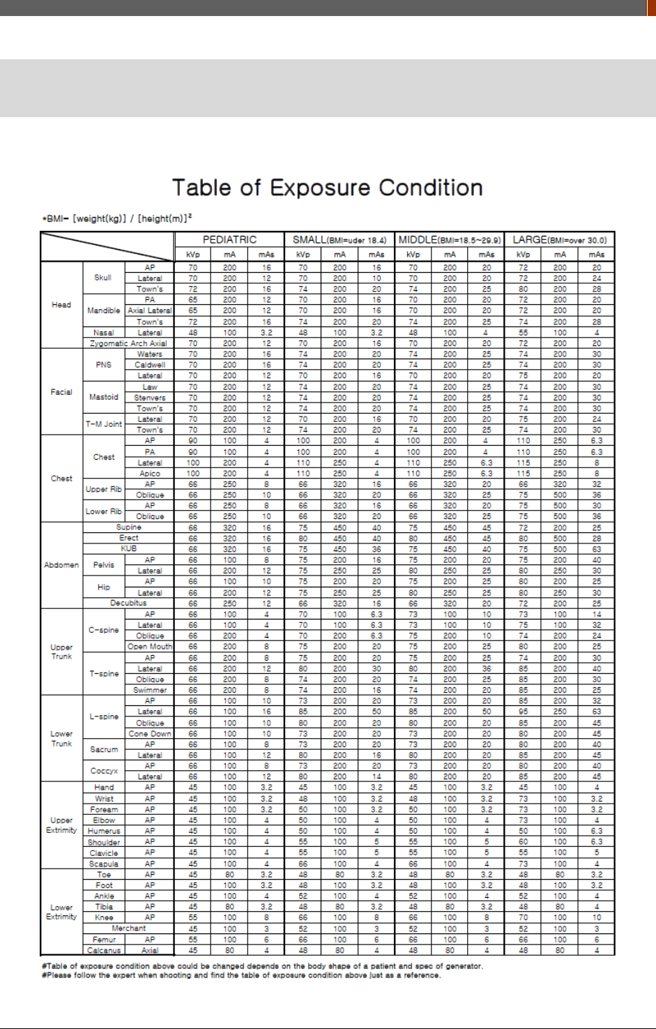
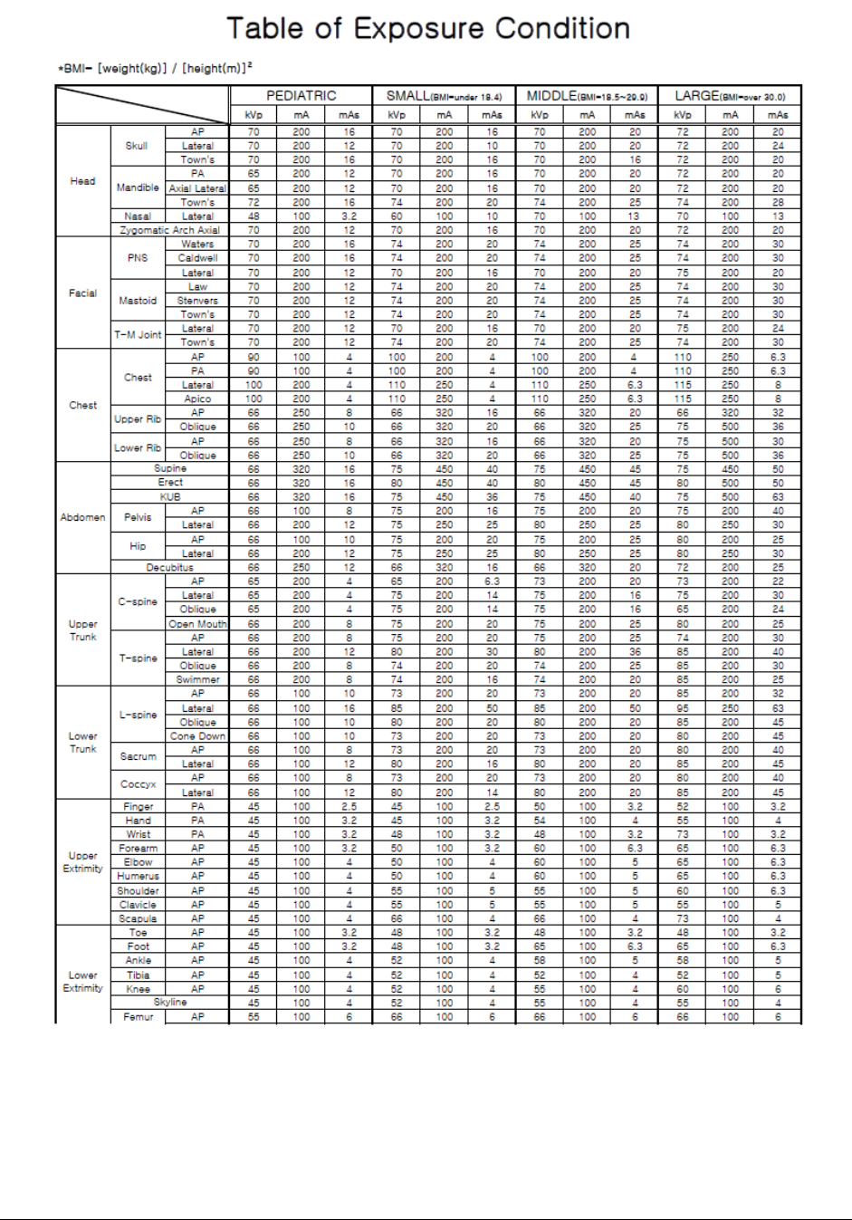
Supplement.3 Recommended exposure condition
table
For 1417WCC
1417WGC/WCC 142
For 1417WGC

PART II. Service Manual
1417WGC/WCC 143
14, Samsung 1-ro 1-gil, Hwaseong-si, Gyeonggi-do, Korea
Tel: +82-31-8015-6245 Fax: +82-31-8015-6300 E-mail: marketing@rayence.com
www.rayence.com