Rayence RYRWM001A Wireless LAN Module User Manual 1417WCC WGC
Rayence Co., Ltd. Wireless LAN Module 1417WCC WGC
UserManual.wiki
>
Rayence
>
RYRWM001A User Manual
>
Host User Manual Part 2
Contents
1.
User Manual
2.
Host User Manual Part 1
3.
Host User Manual Part 2
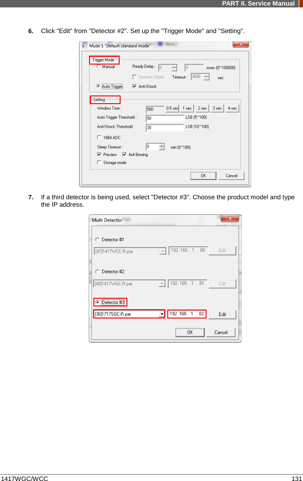
Host User Manual Part 2
Navigation menu
Upload a User Manual
Namespaces
Wiki Guide
HTML
PDF
Info
Views
User Manual
Discussion / Help
Navigation

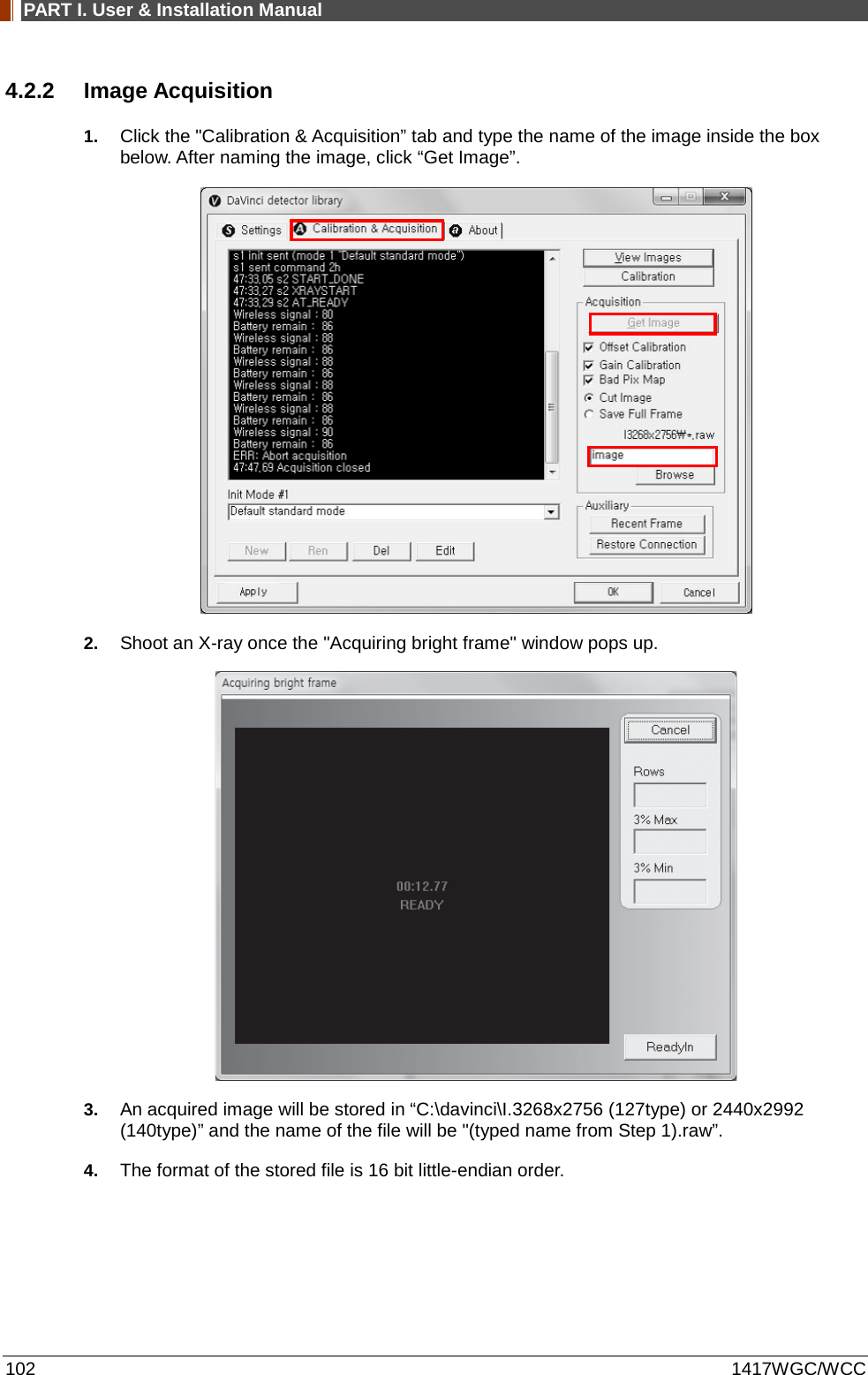

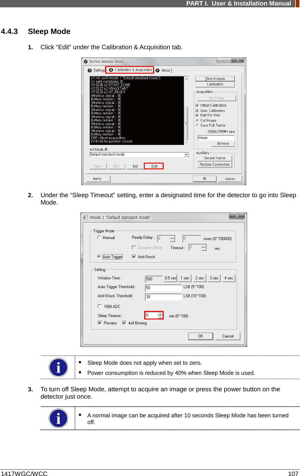
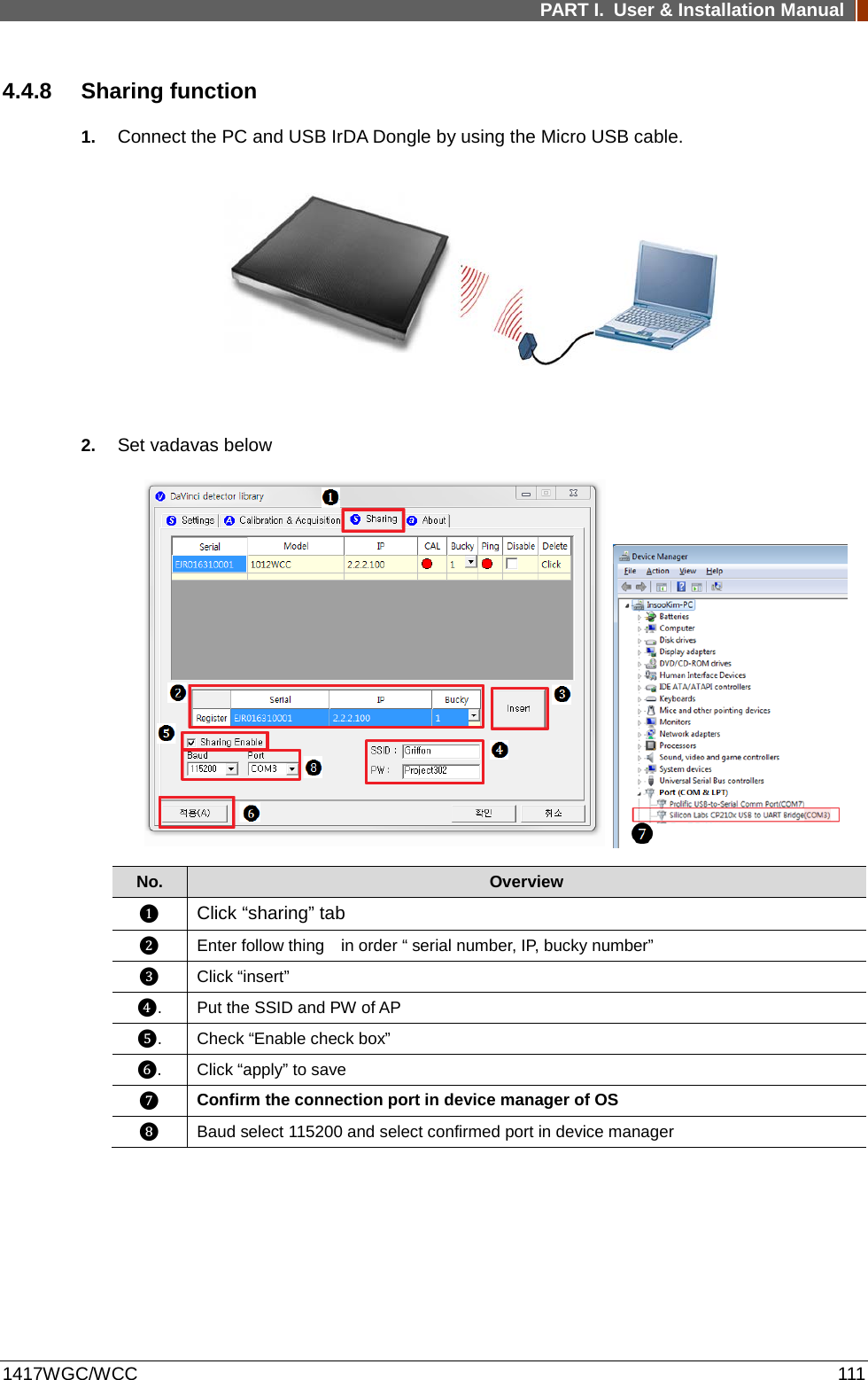
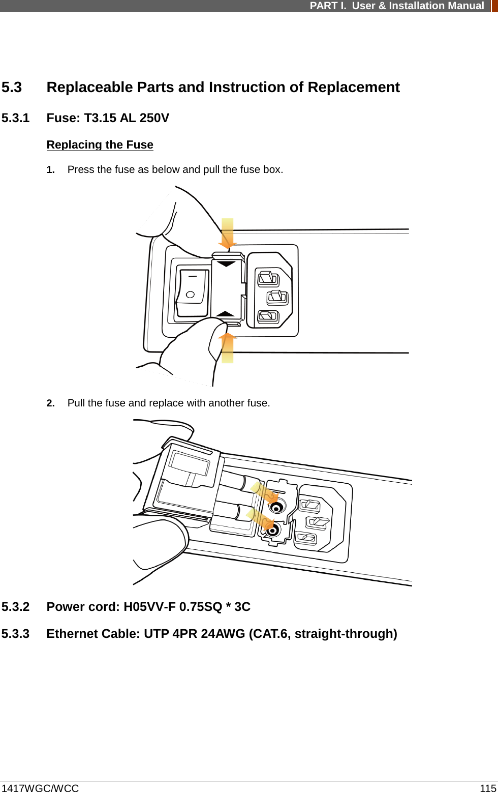

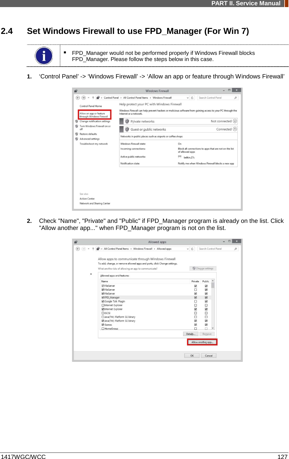
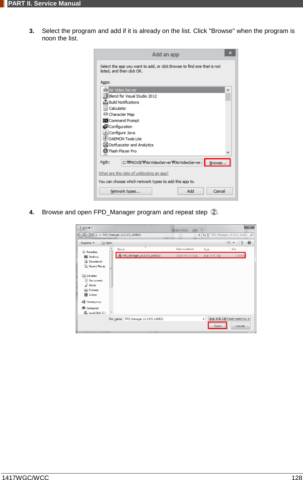
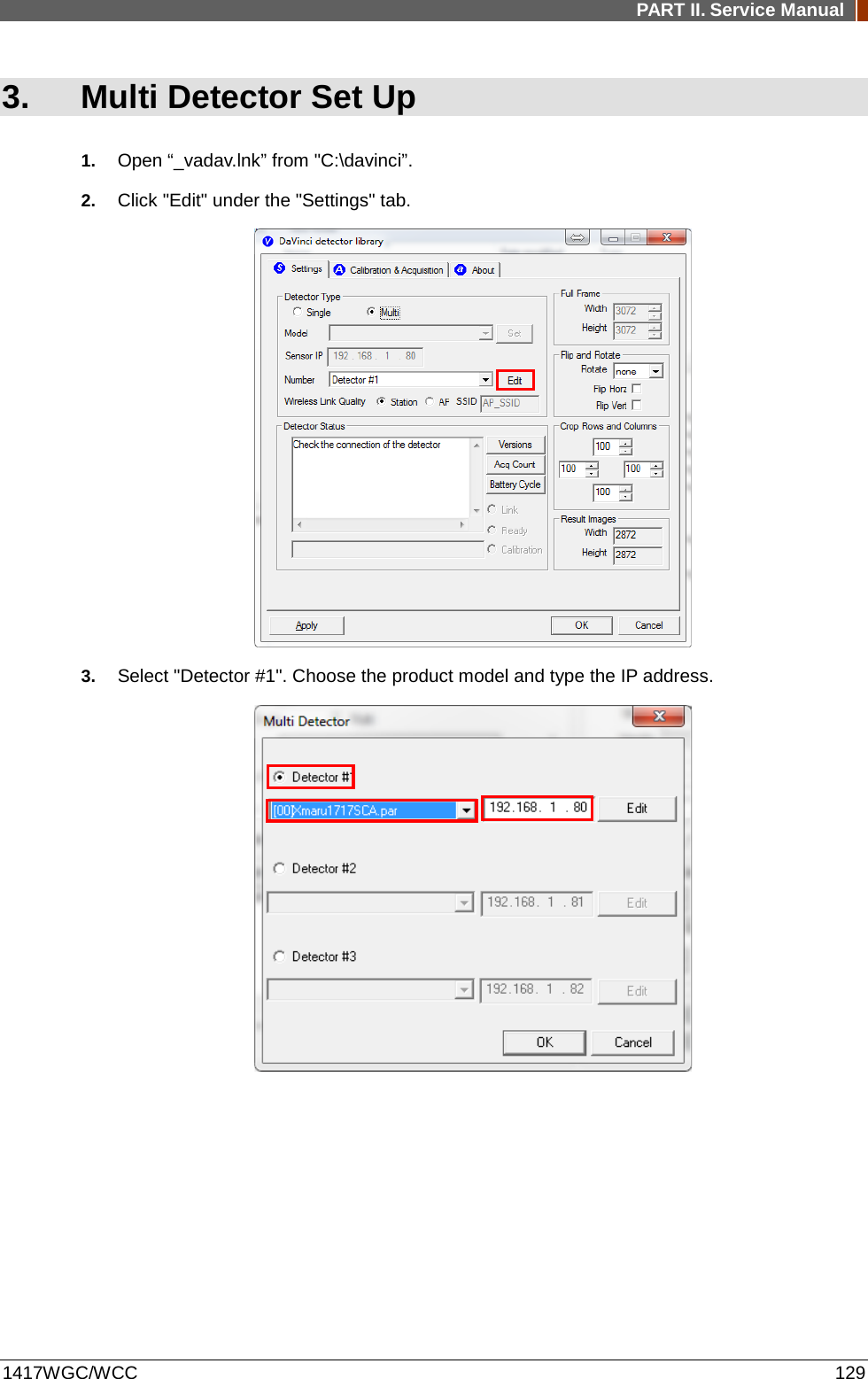
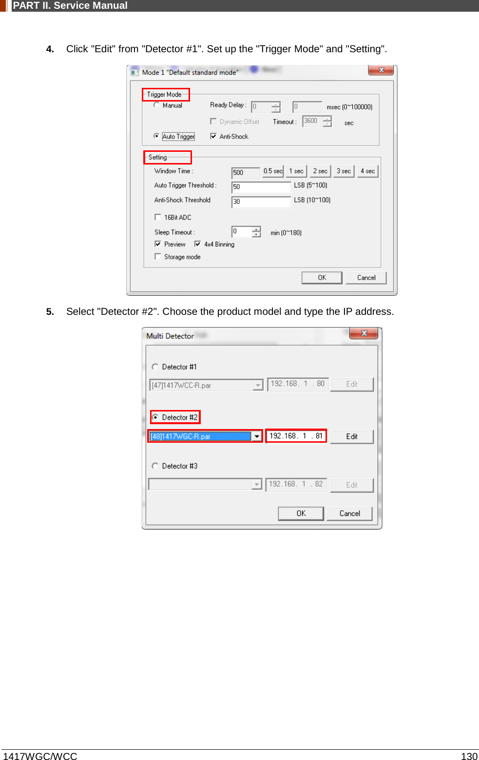
![PART II. Service Manual 1417WGC/WCC 121 2. FPD Manager Instruction (IP, SSID Set Up / Firmware, FPGA Update) 2.1 Detector IP Address Set Up 1. Turn on the power of detector and connect with PC. (IP address: 2.2.2.100) [Connect as wired mode (IP address: 2.2.2.101) with Link cable or wireless mode (IP address: 2.2.2.100).] 2. After the power of detector is on, open "FPD_Manager.exe". 3. Type detector's current IP address at "Detector IP Address" from "Current Setting" as below. Detector's Ethernet Controller is operated with Second IP address, 192.168.124.80.](https://usermanual.wiki/Rayence/RYRWM001A.Host-User-Manual-Part-2/User-Guide-3354280-Page-24.png)
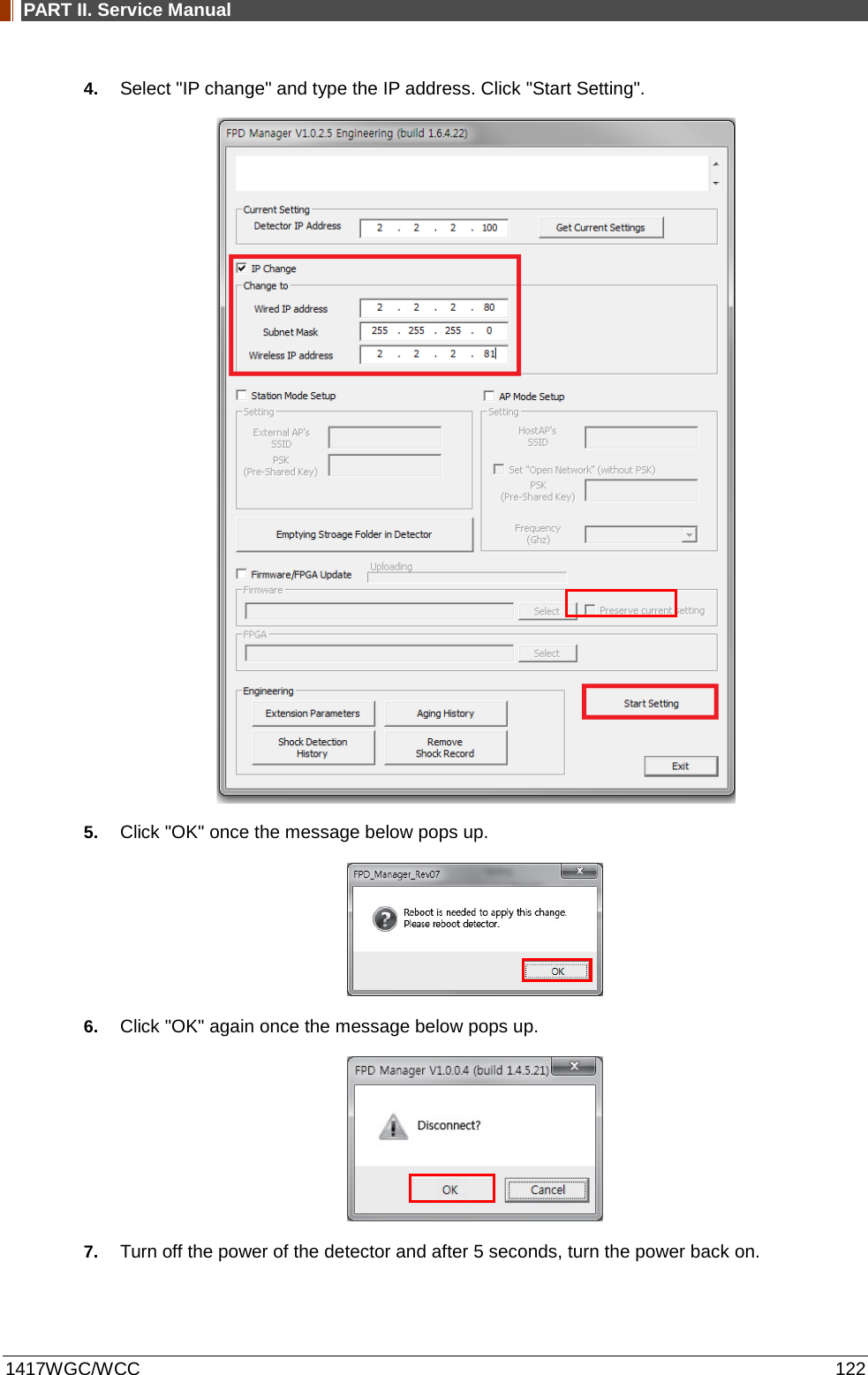
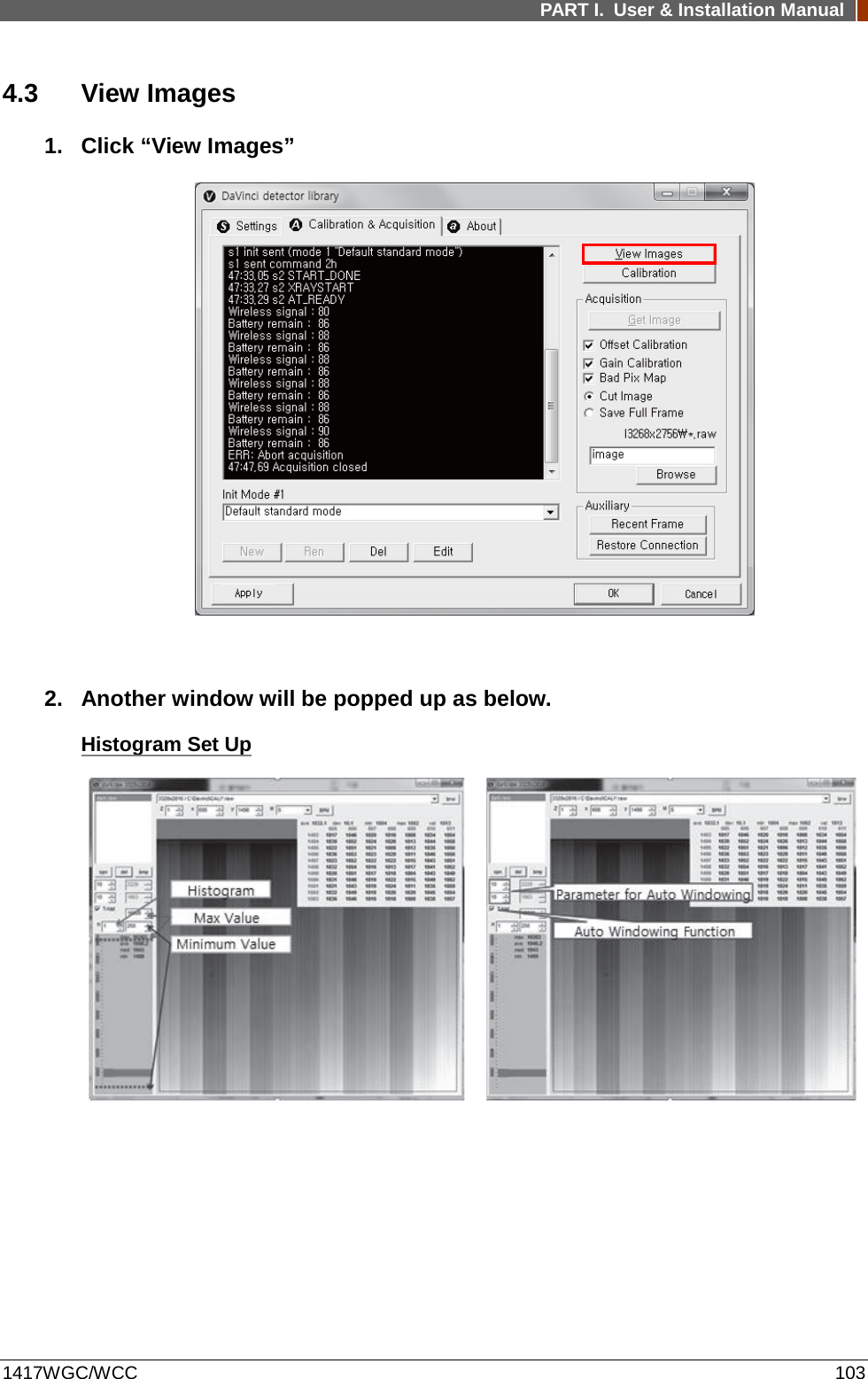
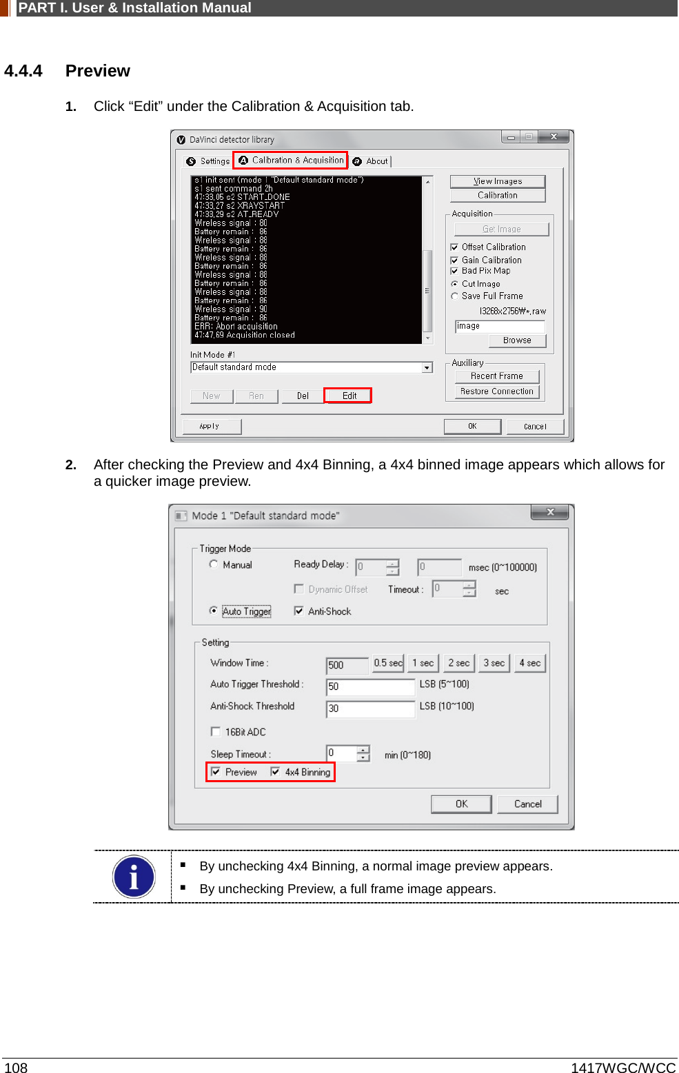
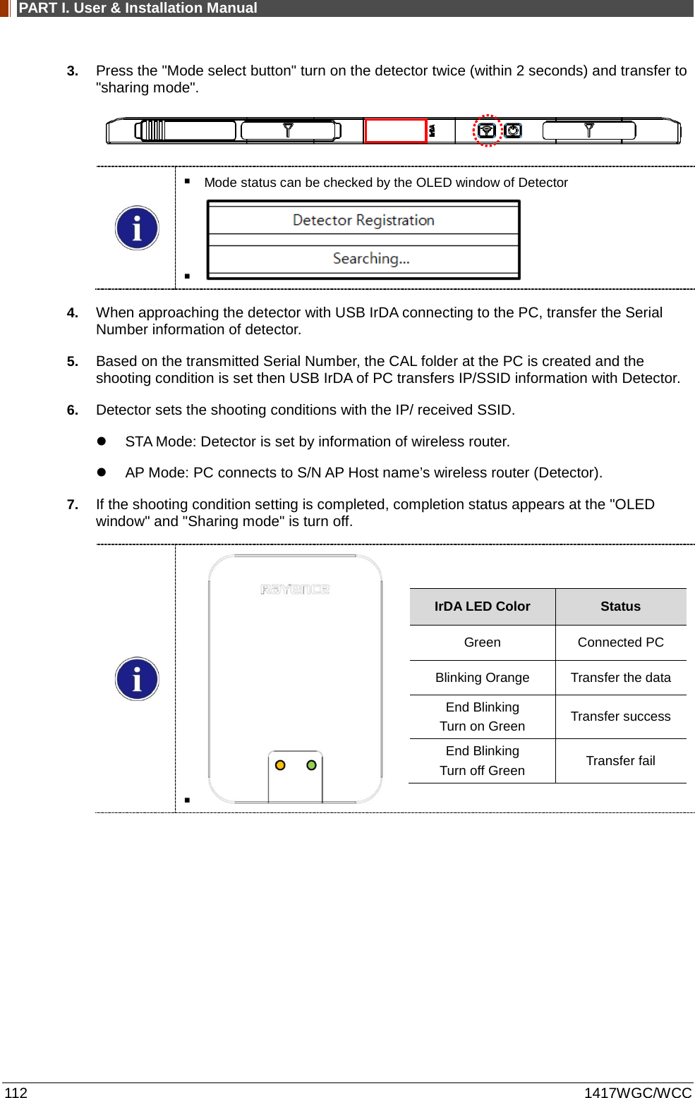
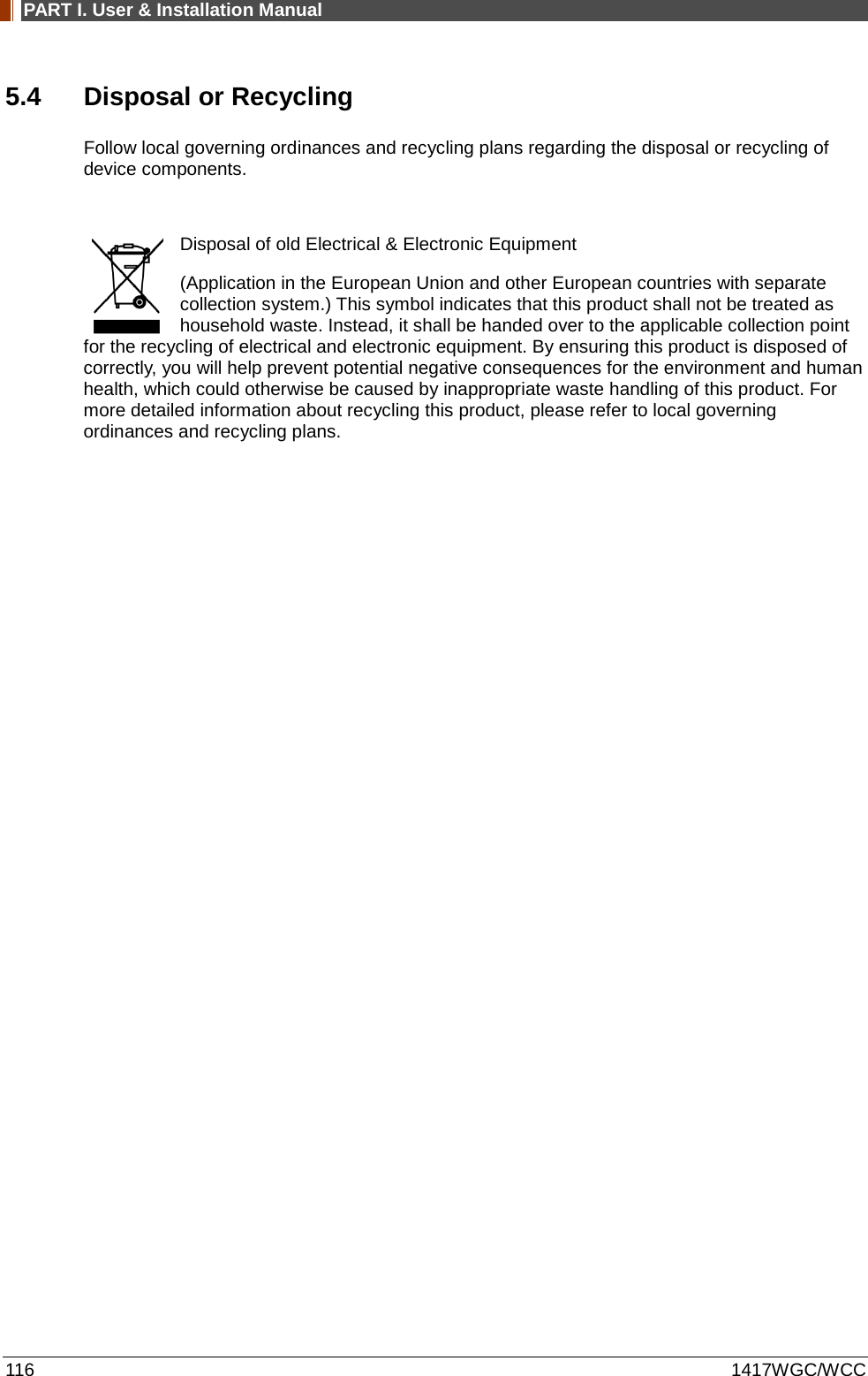
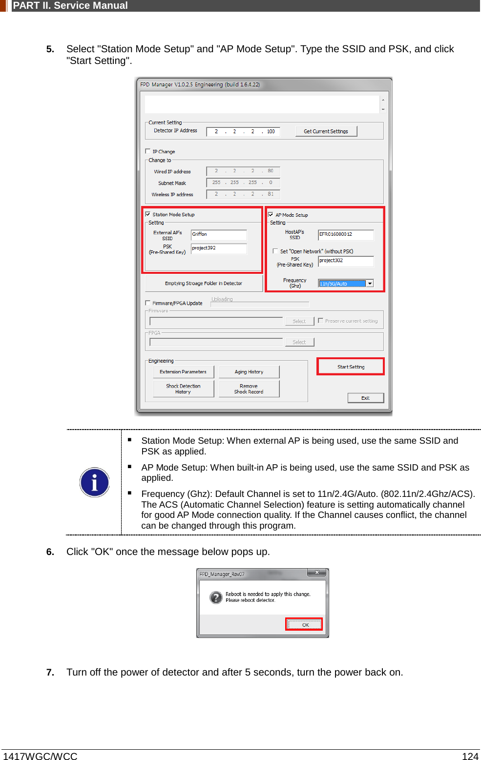
![PART II. Service Manual 1417WGC/WCC 123 2.2 SSID, PSK (Pre-Shared Key) Set Up 1. Turn on the power of the detector and connect it to the PC. (IP address: 2.2.2.100) [Connect as wired mode (IP address: 2.2.2.101) with Link cable or wireless mode (IP address: 2.2.2.100).] 2. After the power of detector is on, open "FPD_Manager.exe". 3. Type the detector's current IP address in "Detector IP Address" from "Current Setting" as below. Detector's Ethernet Controller is operated with Second IP address, 192.168.124.80. 4. Current SSID and PSK (Pre-Shared Key) is displayed once the "Get Current Settings" button is pressed.](https://usermanual.wiki/Rayence/RYRWM001A.Host-User-Manual-Part-2/User-Guide-3354280-Page-26.png)
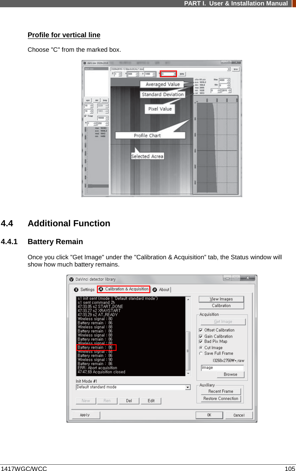
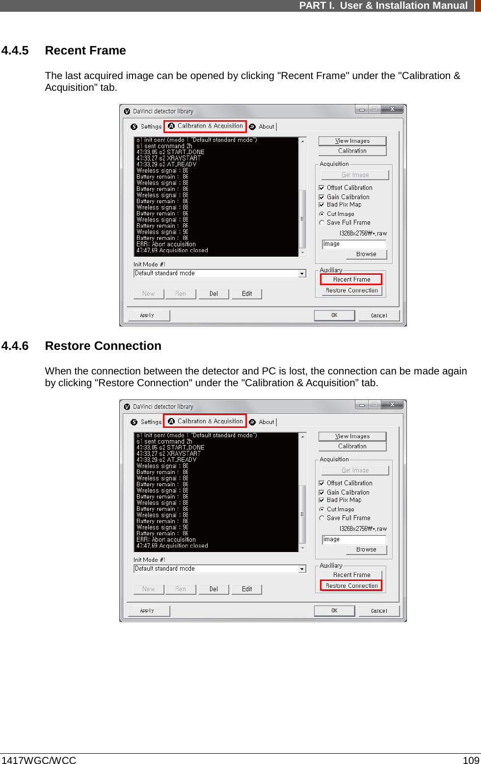
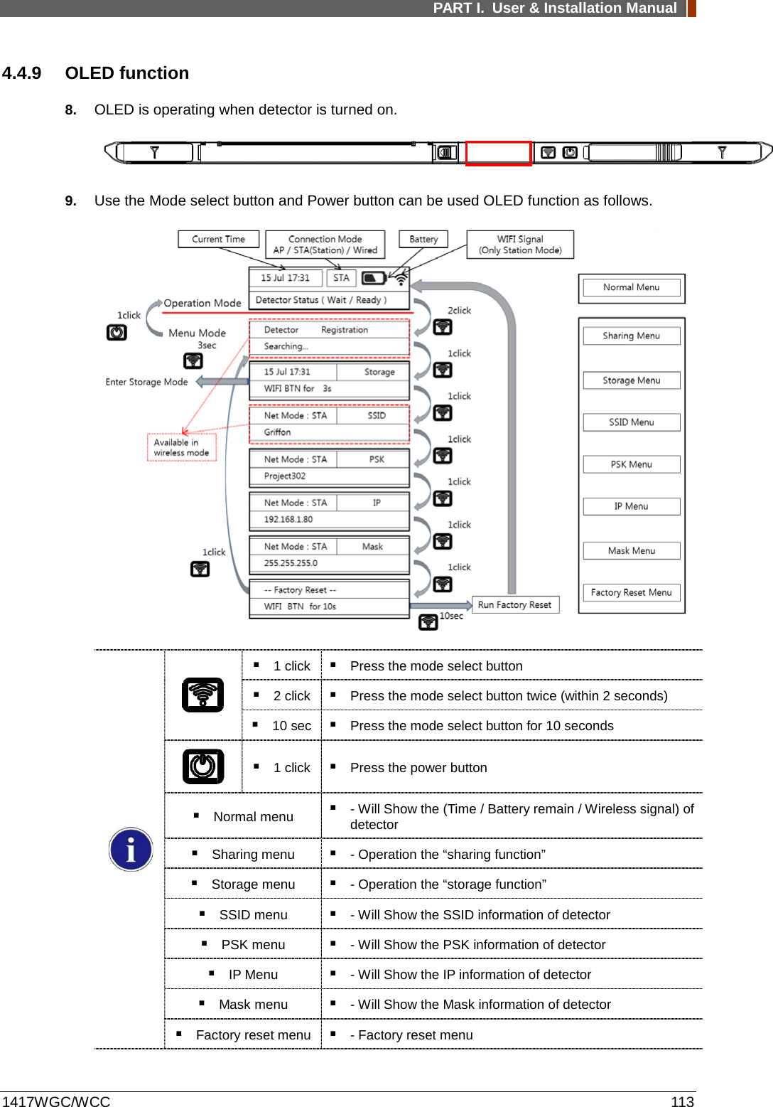
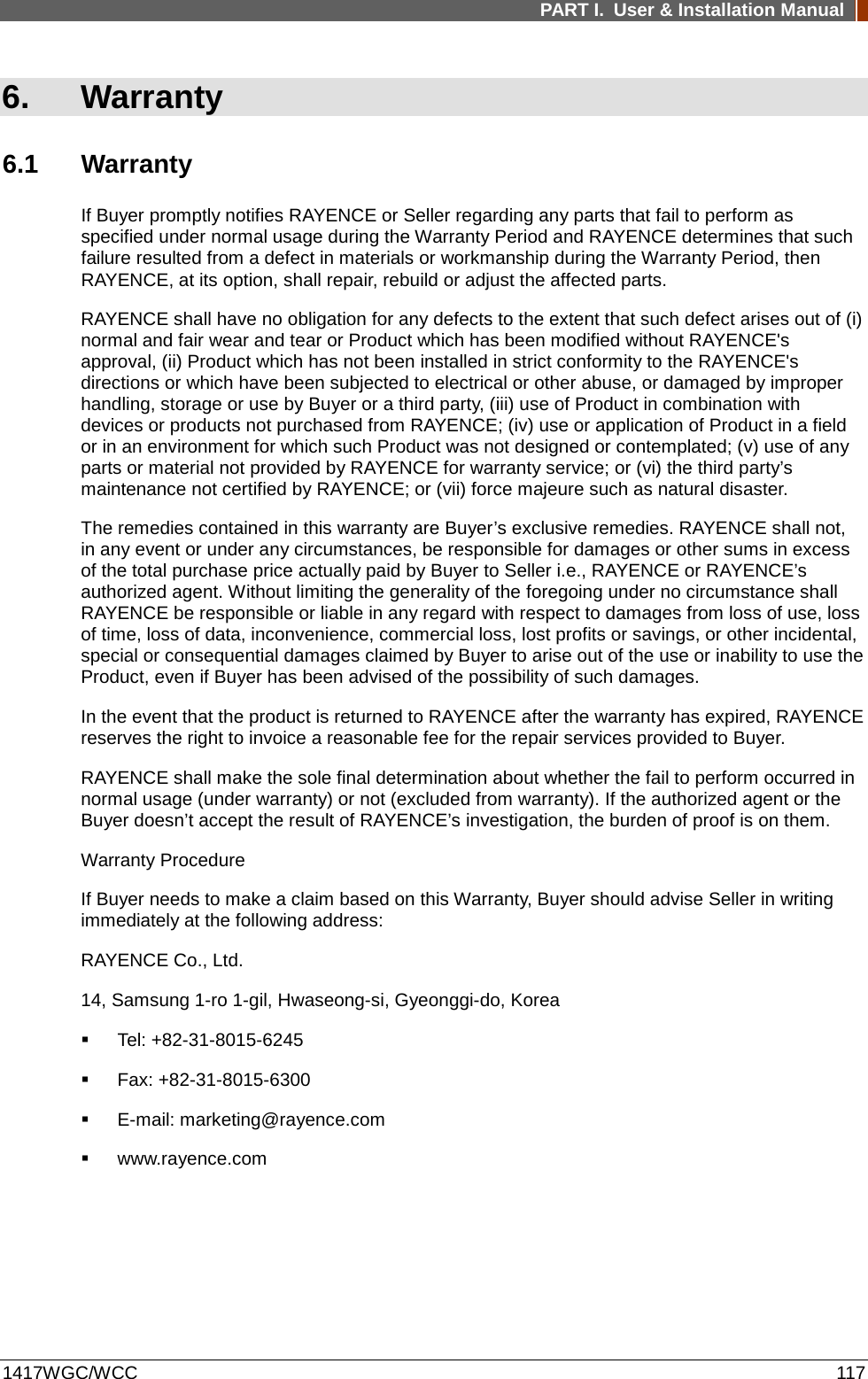
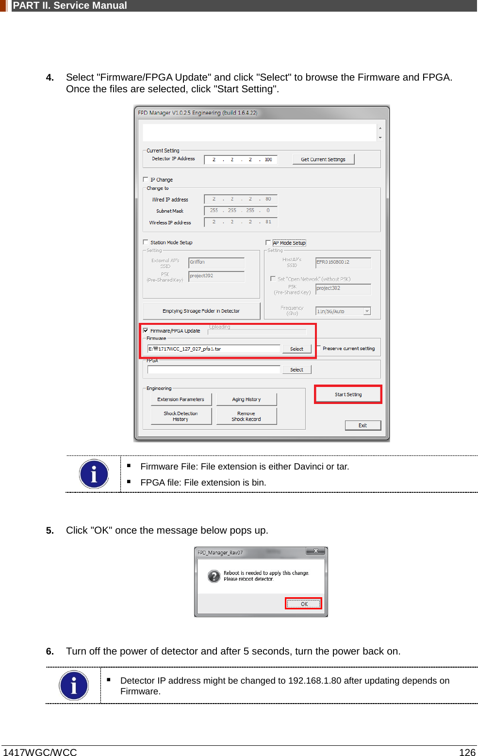
![PART II. Service Manual 1417WGC/WCC 125 2.3 Firmware, FPGA Update 1. Turn on the power of the detector and connect it to the PC. [Connect as wired mode (IP address: 2.2.2.101) with Link cable or wireless mode (IP address: 2.2.2.100).] 2. After the power of detector is on, open "FPD_Manager.exe". 3. Type the detector's current IP address in "Detector IP Address" from "Current Setting" as below. Detector's Ethernet Controller is operated with Second IP address, 192.168.124.80.](https://usermanual.wiki/Rayence/RYRWM001A.Host-User-Manual-Part-2/User-Guide-3354280-Page-28.png)

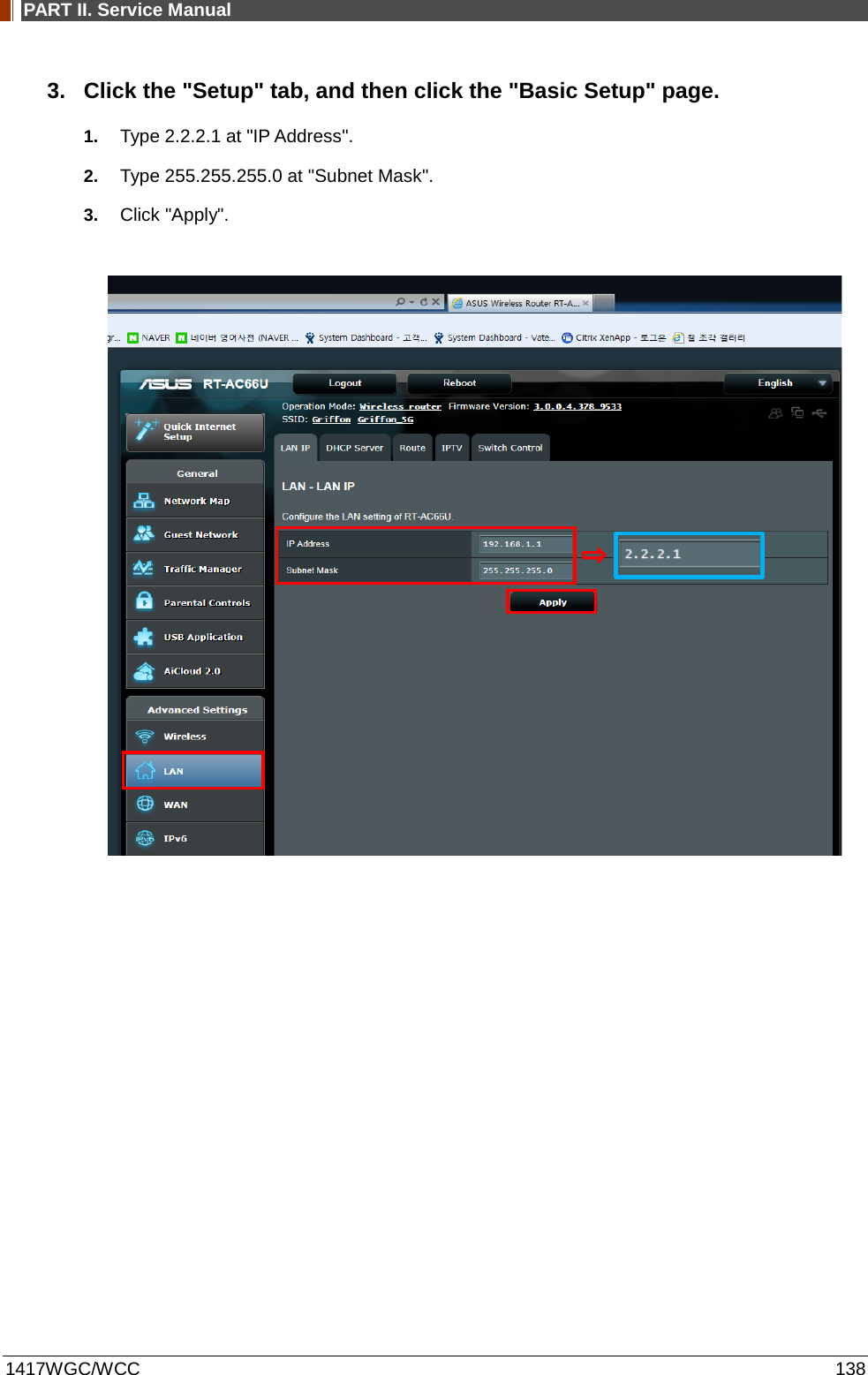
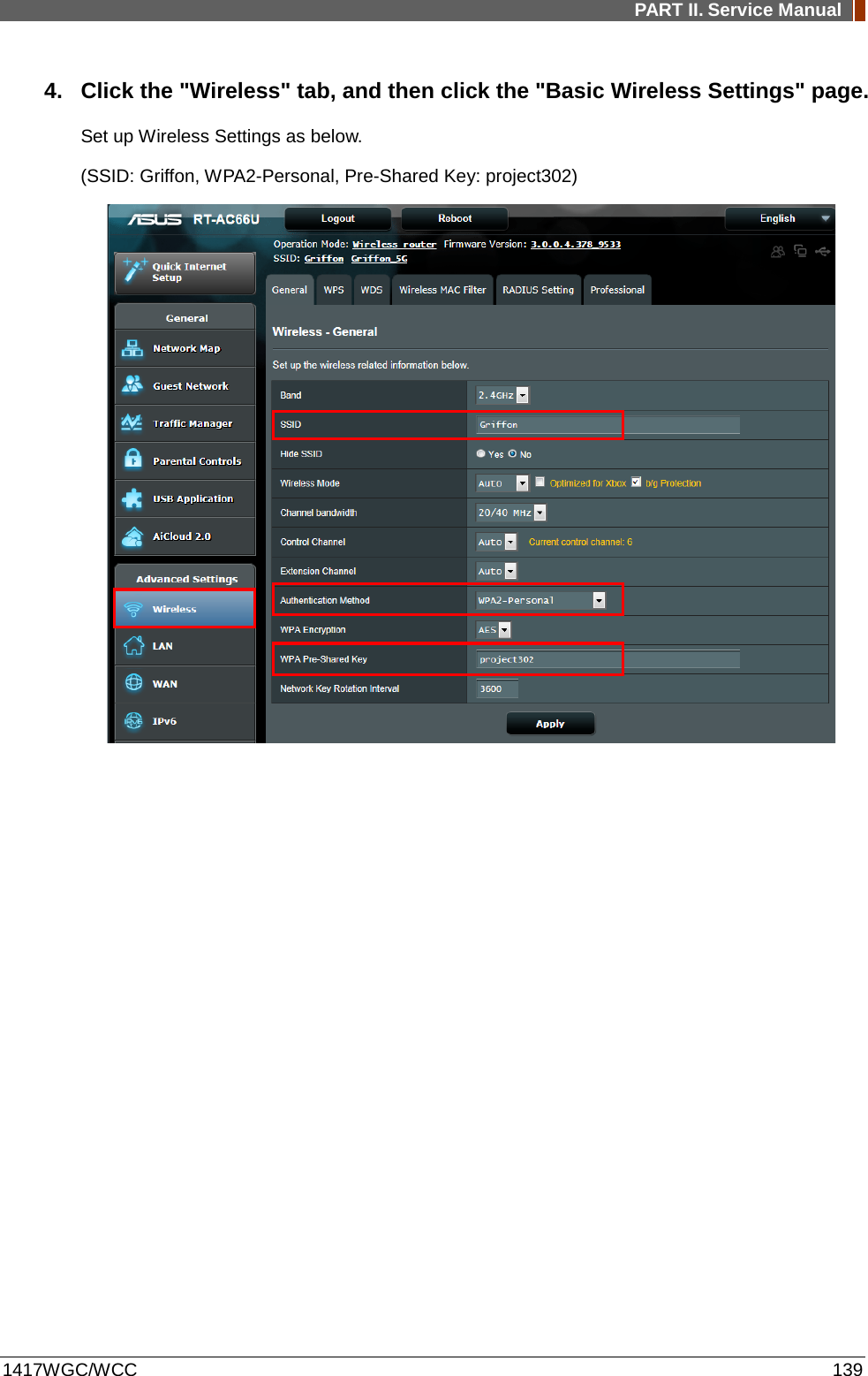
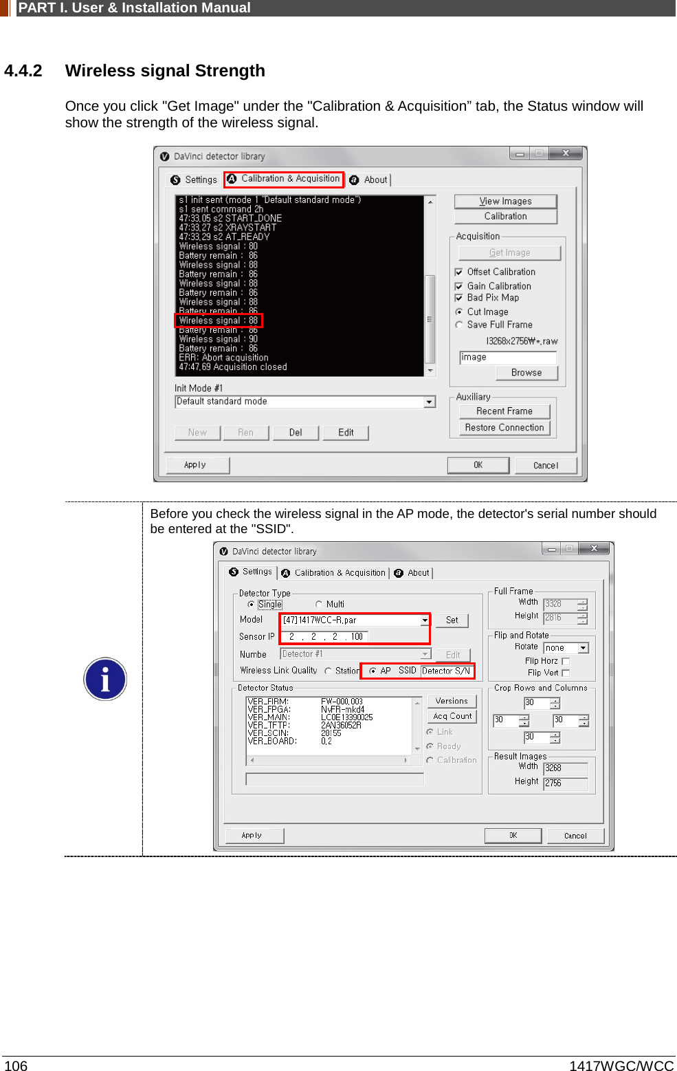
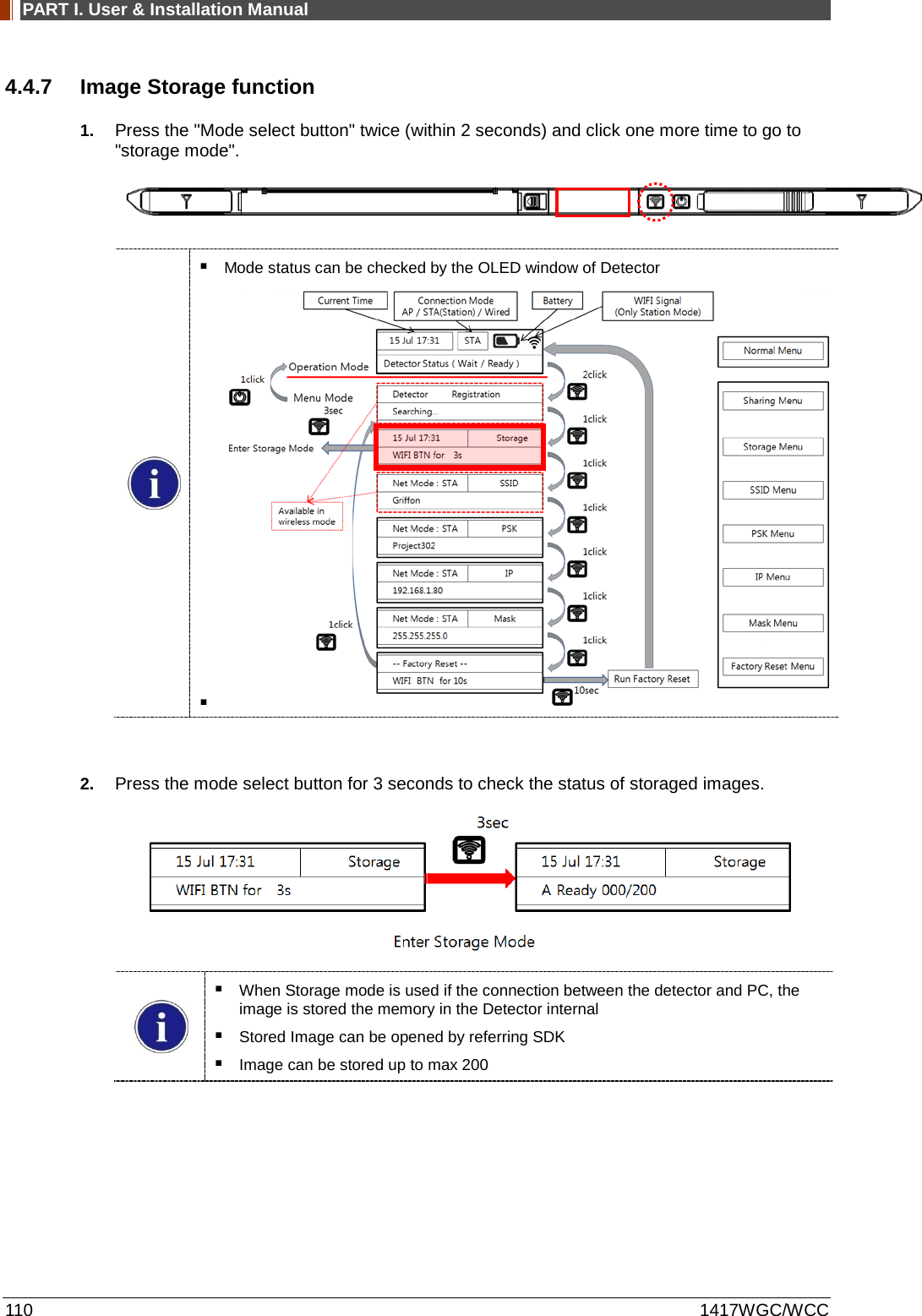
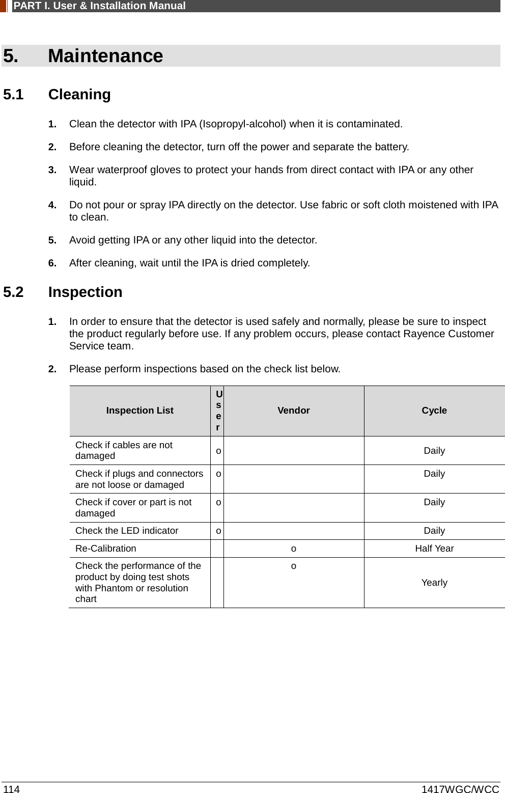
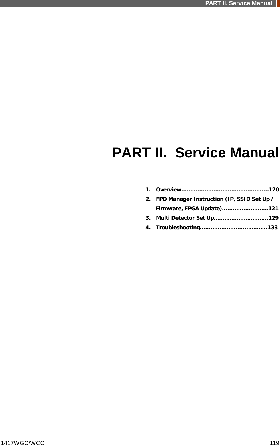
![PART II. Service Manual 1417WGC/WCC 137 Supplement.1 Wireless AP Set Up Instruction (WAP Model: ASUS RT-AC66U) 1. Connect the LAN cable from the Ethernet port #1 on the PC to the Ethernet port #1 on the AP. 2. Access AP Set Up Page 1. Open a web browser. Once type 192.168.1.1. In the browser address bar a login window appears. 2. Enter the ID and password. 3. Click "Ok". [ID: admin | PW: admin] IP address for the first access is 192.168.1.1. After changing the IP address to 2.2.2.1, use IP address 2.2.2.1 for accessing. ① ② ③](https://usermanual.wiki/Rayence/RYRWM001A.Host-User-Manual-Part-2/User-Guide-3354280-Page-40.png)