Rayence RYRWM001A Wireless LAN Module User Manual 1417WCC WGC
Rayence Co., Ltd. Wireless LAN Module 1417WCC WGC
UserManual.wiki
>
Rayence
>
RYRWM001A User Manual
>
Host User Manual Part 1
Contents
1.
User Manual
2.
Host User Manual Part 1
3.
Host User Manual Part 2
Host User Manual Part 1
Navigation menu
Upload a User Manual
Namespaces
Wiki Guide
HTML
PDF
Info
Views
User Manual
Discussion / Help
Navigation
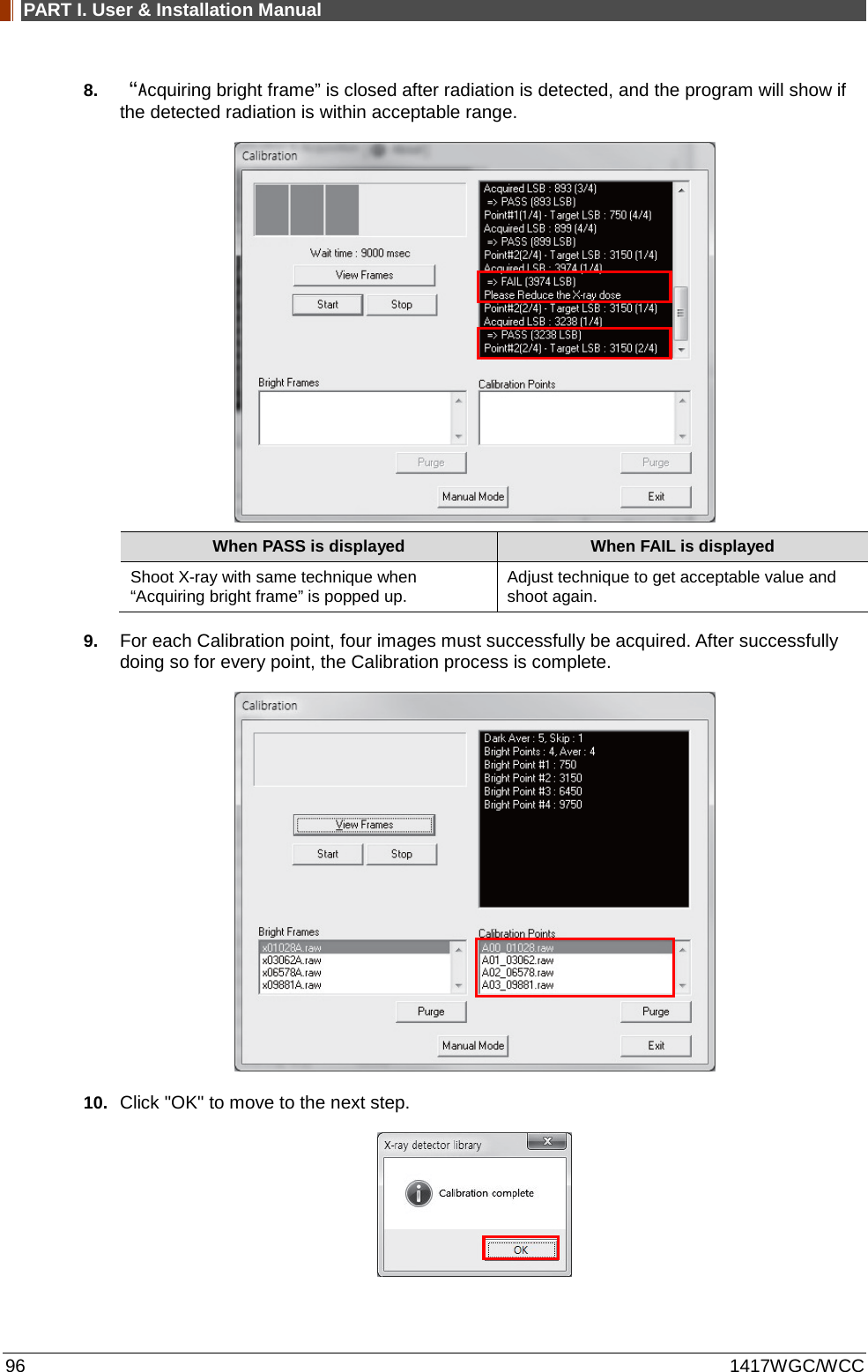
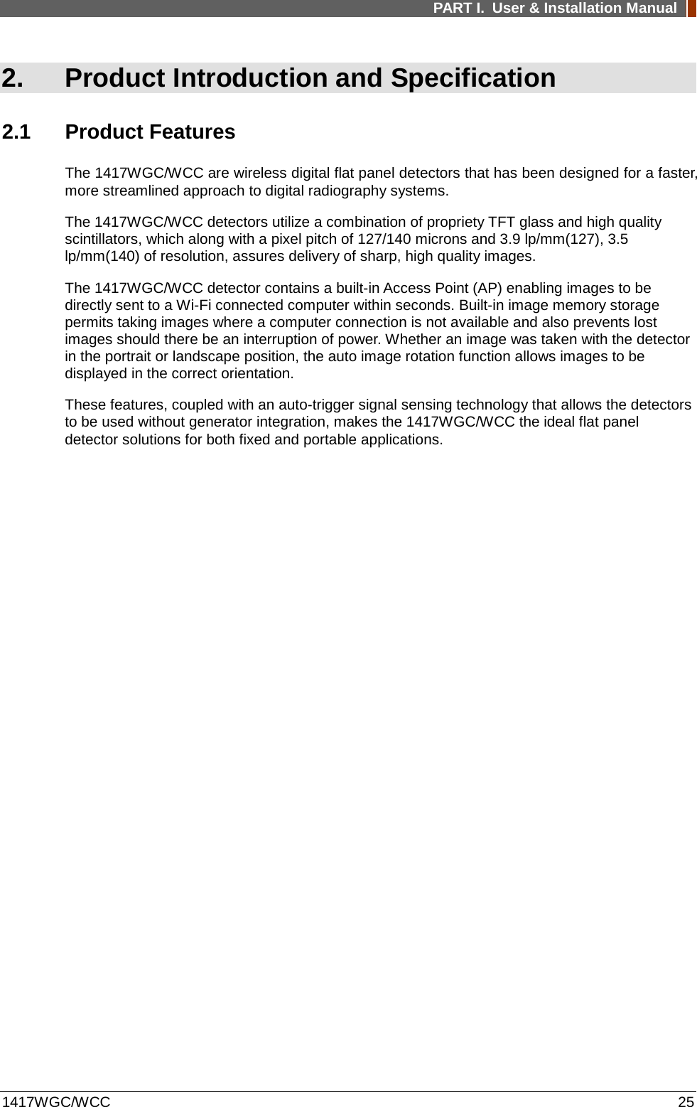
![PART I. User & Installation Manual 1417WGC/WCC 19 CAUTION otherwise subjected to damage or stress. CAUTION Maintenance and Inspection For safety reasons, be sure to inspect the detector before using it. In addition, carry out a regular inspection at least once a year. If the detector is defective, do not disassemble the detector randomly. Maintenance of the detector should be done by an authorized service provider. Please contact Rayence Customer Service team or authorized agent. Be sure to check the user’s manual for replaceable components. CAUTION Modifications Any changes or modifications in construction of this detector which are not expressly approved by the party responsible for compliance could void the user’s authority to operate the detector. CAUTION Battery Do not let the detector or battery come in contact with liquids. Liquids can get into the detector’s circuits, leading to corrosion. Even when the detector appears to be dry and appears to operate normally, the circuitry could slowly corrode and pose a safety hazard. If the battery gets wet, have them checked by authorized agent or contact Rayence Customer Service team, even if they appear to be working properly. Do not place your battery near a heat source. Excessive heating can damage the detector or the battery and could cause the detector or the battery to explode. Do not dry a wet or damp battery with an appliance or heat source such as a microwave oven, hair dryer, iron, or radiator. Do not dispose of the detector or the battery in a fire. The detector or the battery may explode when overheated. Use only Rayence-approved batteries [Model: RB37WHA] and recharge your battery only with Rayence-approved chargers [Model: RC120WA/RMC001A] which are specifically designed for your detector. Use of a non-Rayence-approved battery or charger may present a risk of fire, explosion, leakage, or other hazard. Rayence’s warranty does not cover damage to the detector caused by non-Rayence-approved batteries and/or chargers. Misuse or use of incompatible batteries and charging detectors could result in damage to the detector and a possible risk of fire, explosion, or leakage, leading to serious injuries, damages to your detector, or other serious hazard. Check the battery status frequently to avoid battery empty. When the low battery LED of detector is turned on, change the battery or charge the battery using cable. CAUTION Recommendations to equipment manufacturers and battery assemblers The following represents a typical, but non-exhaustive, list of good advice to be provided by the manufacturer of secondary cells and batteries to equipment manufacturers and battery assemblers. Do not dismantle, open or shred cells. Batteries should be dismantled only by trained personnel. Multicell battery cases should be designed so that they can be opened only with the aid of a tool. Do not short-circuit a cell or battery. Do not store cells or batteries haphazardly in a box or drawer where they may short-circuit each other or be short-circuited by conductive materials. Do not remove a cell or battery from its original packaging until required for use. Do not expose cells or batteries to heat or fire. Avoid storage in direct sunlight.](https://usermanual.wiki/Rayence/RYRWM001A.Host-User-Manual-Part-1/User-Guide-3354279-Page-19.png)

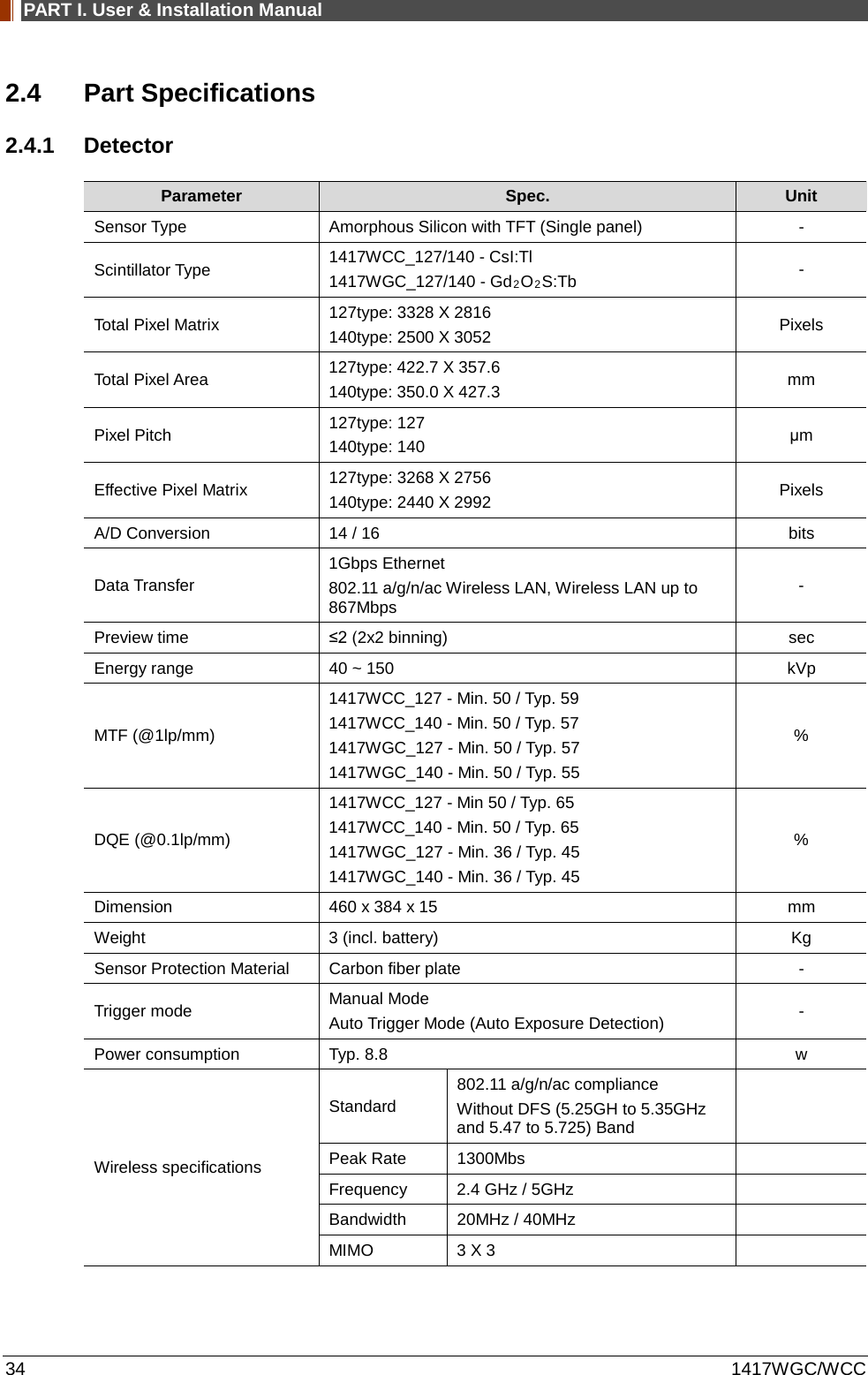
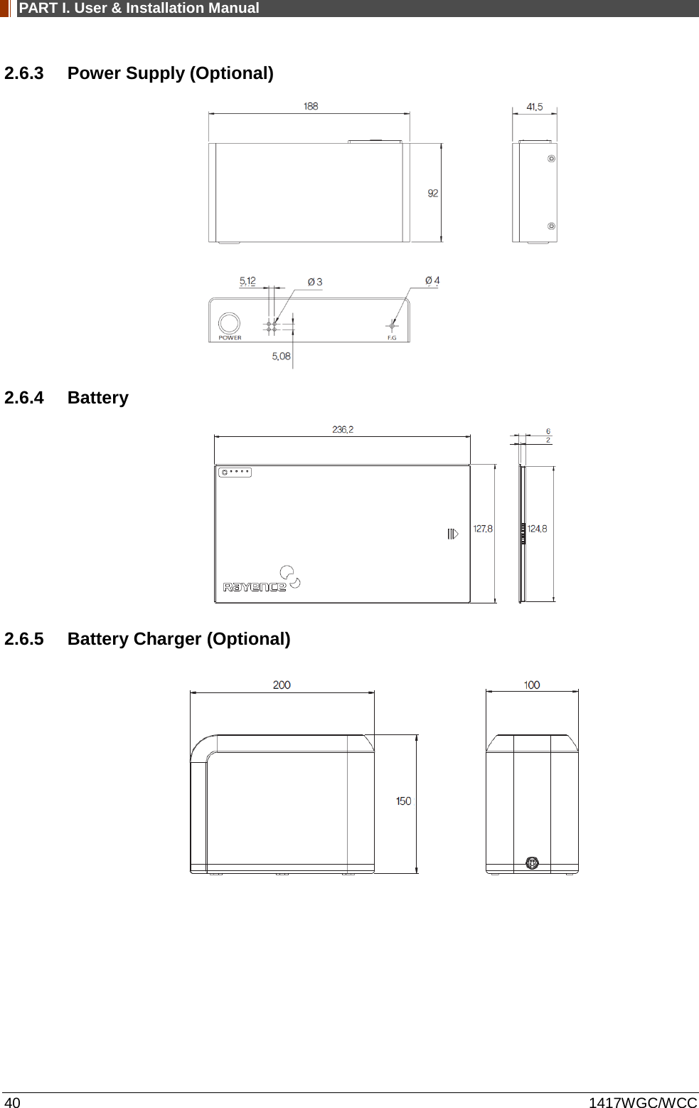
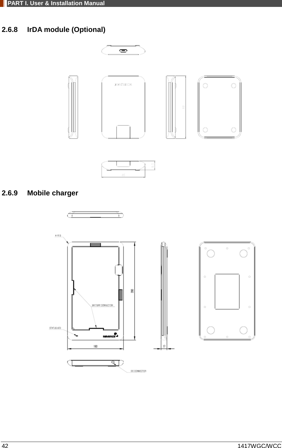
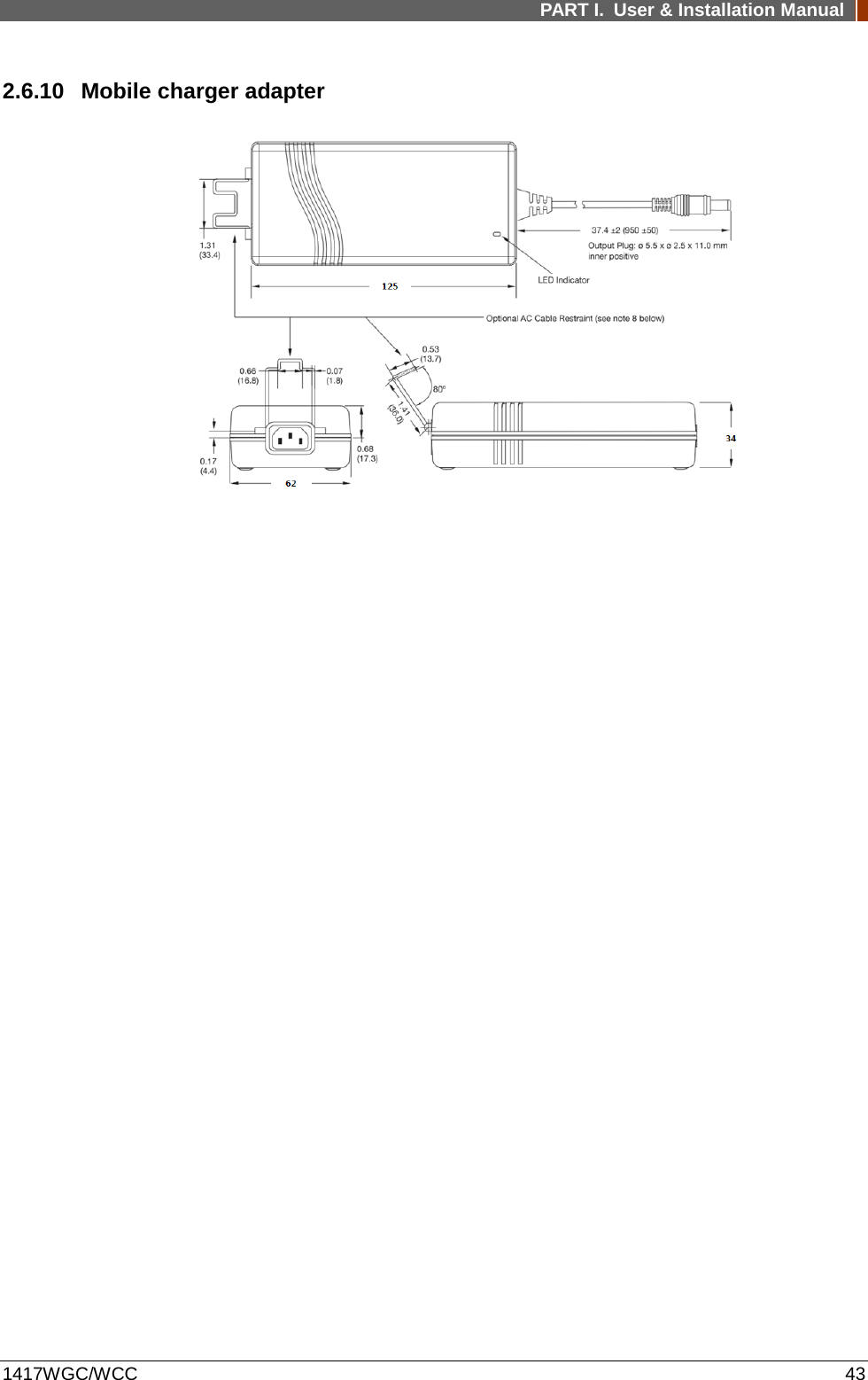
![PART I. User & Installation Manual 1417WGC/WCC 35 Maximum wireless signal rate derived from IEEE standard specifications. Actual data throughput will vary. Network conditions and environmental factors, including volume of network traffic, building materials and construction, and network overhead, lower actual data throughput rate. Recommended Maximum operable distance : 10m (From the Access Point) Wireless Module and Wireless Antenna • Wireless antennas: The module adopts the latest 802.11n Dual-Band technology (2.4Ghz and 5Ghz). The transmitter of the module is powered by host equipment (Detector). The antennas are 2 printed-dipole antennas. • Wireless module: The SparkLAN WPEA-121N 802.11 a/b/g/n/ac half mini PCI-e module is implemented. It supports 3T3R (3 transmit 3 receive) MIMO technology, which delivers throughput up to 1300Mbps.1417WCC/WGC in the RF module does not use DFS band. 2.4.2 Battery [Model name: RB37WHA] Parameter Spec. Unit Size 236.2 x 127.8 x 6 mm Weight 0.3 Kg Input 12.6 VDC Output 11.1 VDC Cycle life Max. 500 cycles Operation temp. range 5~40 ℃ Charging time Typ. 3 hours Capacity Typ. 3400 mAh Operating time Typ. 4 hours 2.4.3 Mobile charger [Model name: RMC001A] Parameter Spec. Unit Dimension 280 X 160 X 17 mm Weight 0.3 Kg Input 18 VDC Output 12.6 VDC 2.4.4 Mobile charger Adaptor [Model name: AFM60US18] Parameter Spec. Unit Dimension 125 X 62 X 34 mm Weight 0.4 Kg Input 80-264VAC, 47~63Hz, 1.5A - Output 18VDC, Max 3.34A -](https://usermanual.wiki/Rayence/RYRWM001A.Host-User-Manual-Part-1/User-Guide-3354279-Page-35.png)
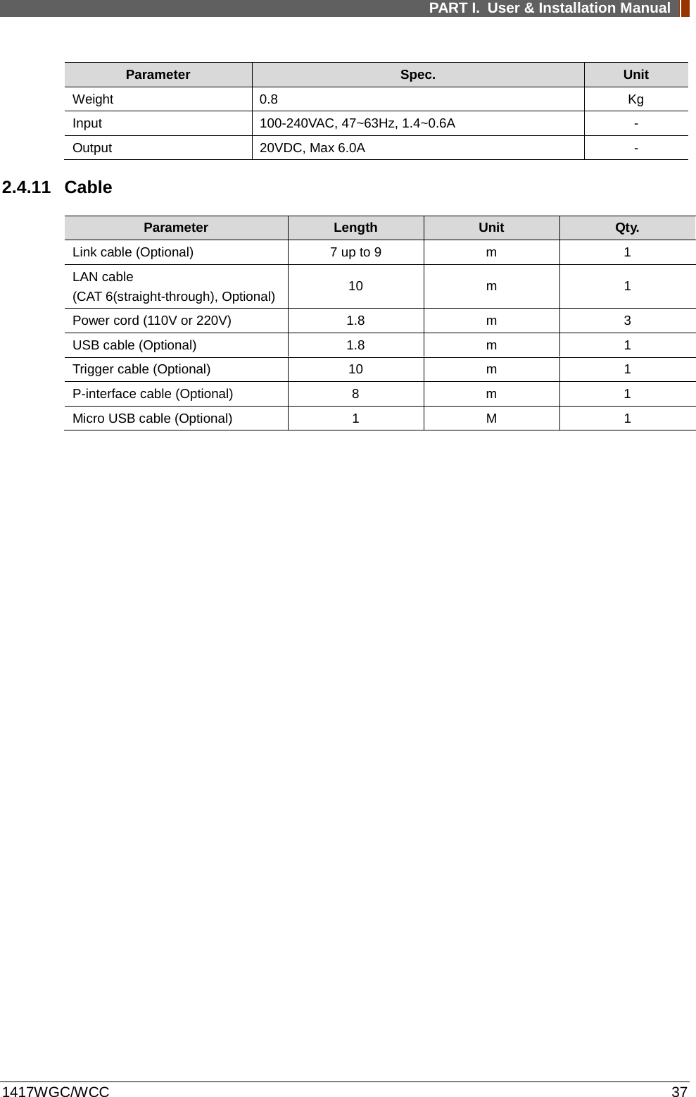
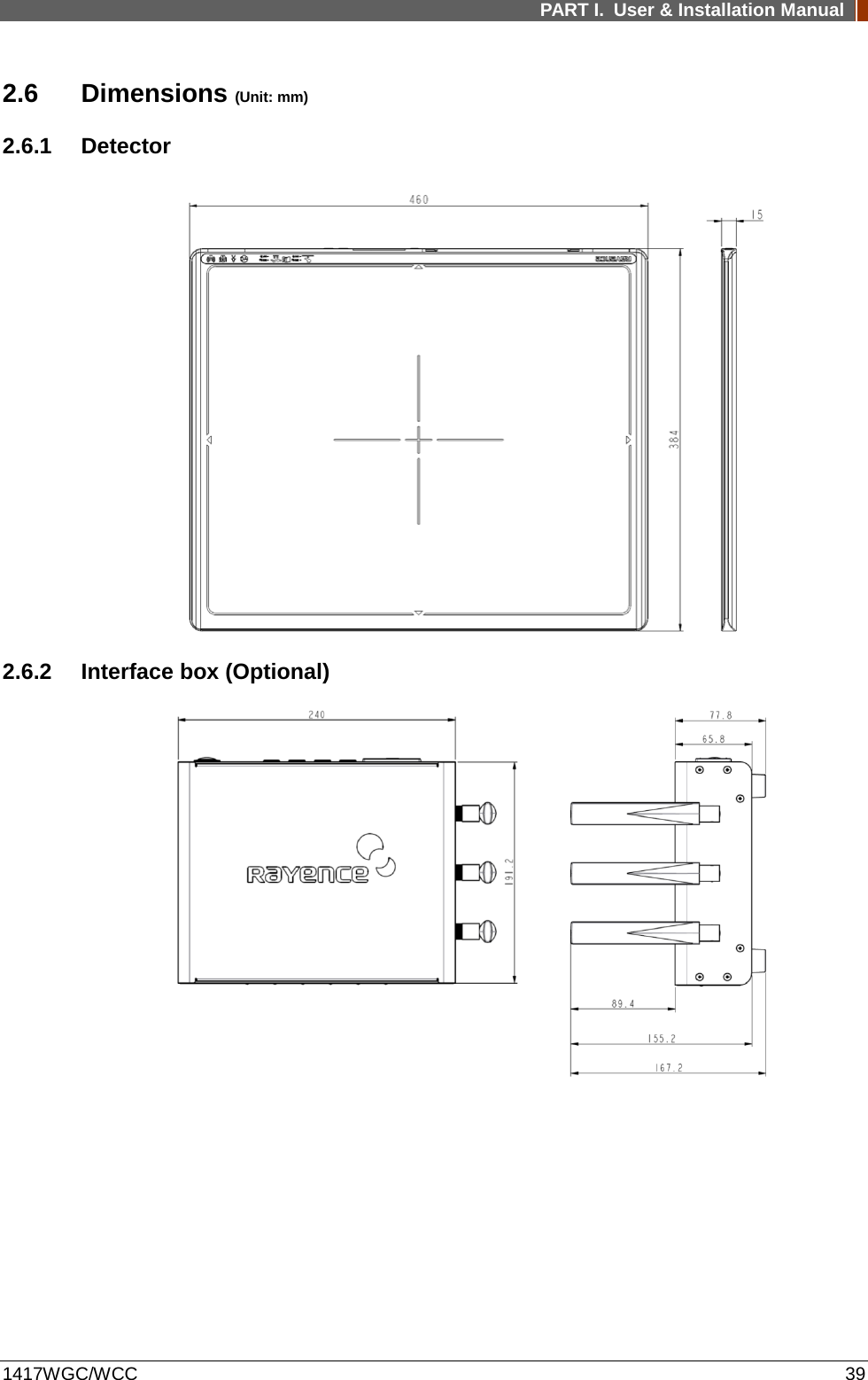
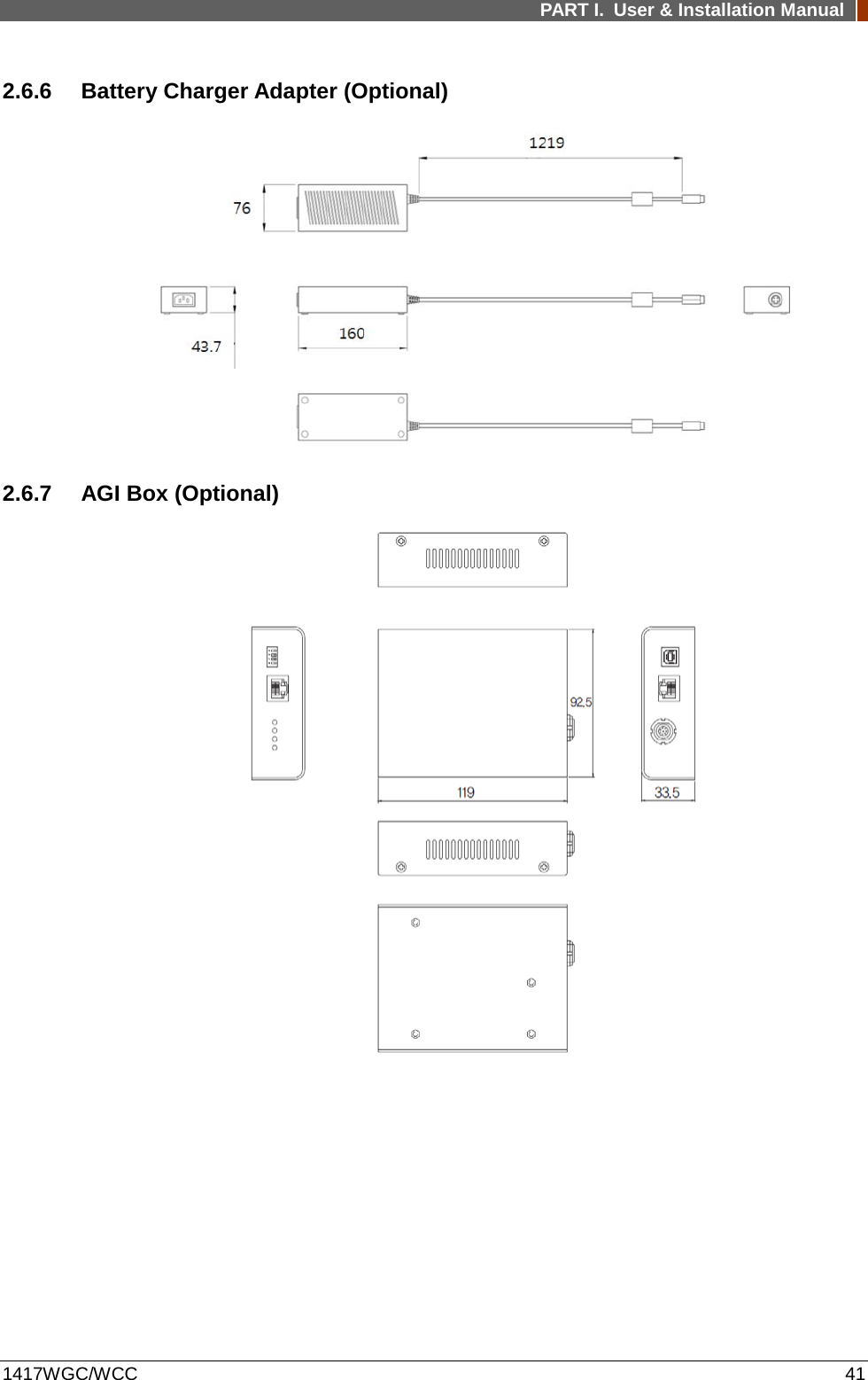
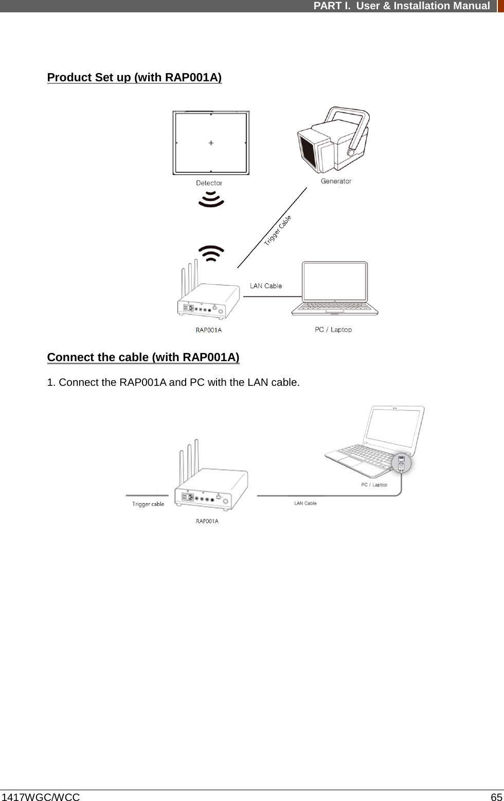
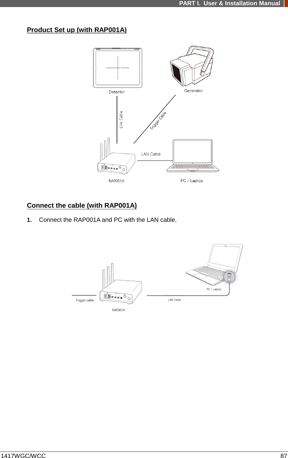
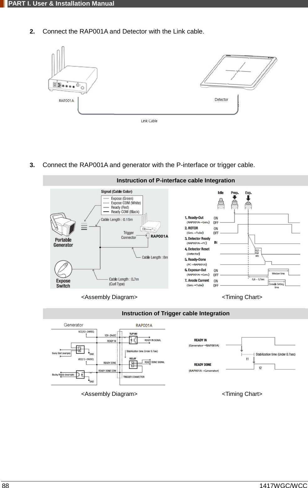
![PART I. User & Installation Manual 36 1417WGC/WCC 2.4.5 Interface box (Optional) [Model name: RAP001A] Parameter Spec. Unit Dimension 240 X 190 X 75 (not incl. antenna) mm Weight 1.85 Kg Input rate 85 ~ 264VAC (50/60Hz) - Output Typ. 24VDC (Max 5.4A) Wireless communication 802.11 a/g/n/ac Wireless LAN, up to 867Mbps - Wired communication Ethernet 1Gbps Detector Port 3 Trigger Port 1 2.4.6 Power Supply (Optional) [Model name -RP003A] Parameter Spec. Unit Dimension 188 X 92 X 41.5 mm Weight 0.5 Kg Rated power supply(Input) 100-240VAC (50/60Hz) - Rated power supply(Output) Typ. 24VDC (Max 1.6A) - 2.4.7 AGI Box (Optional) Parameter Spec. Unit Dimension 92.5 X 119 X 33.5 mm Weight 0.3 Kg 2.4.8 IrDA module (Optional) [Model name – RI001A] Parameter Spec. Unit Dimension 66 X 46 X 9.5 mm Weight 0.1 Kg 2.4.9 Battery Charger (Optional) [Model name: RC120WA] Parameter Spec. Unit Size 200 x 100 x 150 mm Weight 0.9 Kg Input 20 VDC Output 12.6 VDC 2.4.10 Battery Charger Adapter (Optional) [Model name: PMP120-13-3] Parameter Spec. Unit Size 160 x 76 x 43.7 mm](https://usermanual.wiki/Rayence/RYRWM001A.Host-User-Manual-Part-1/User-Guide-3354279-Page-36.png)
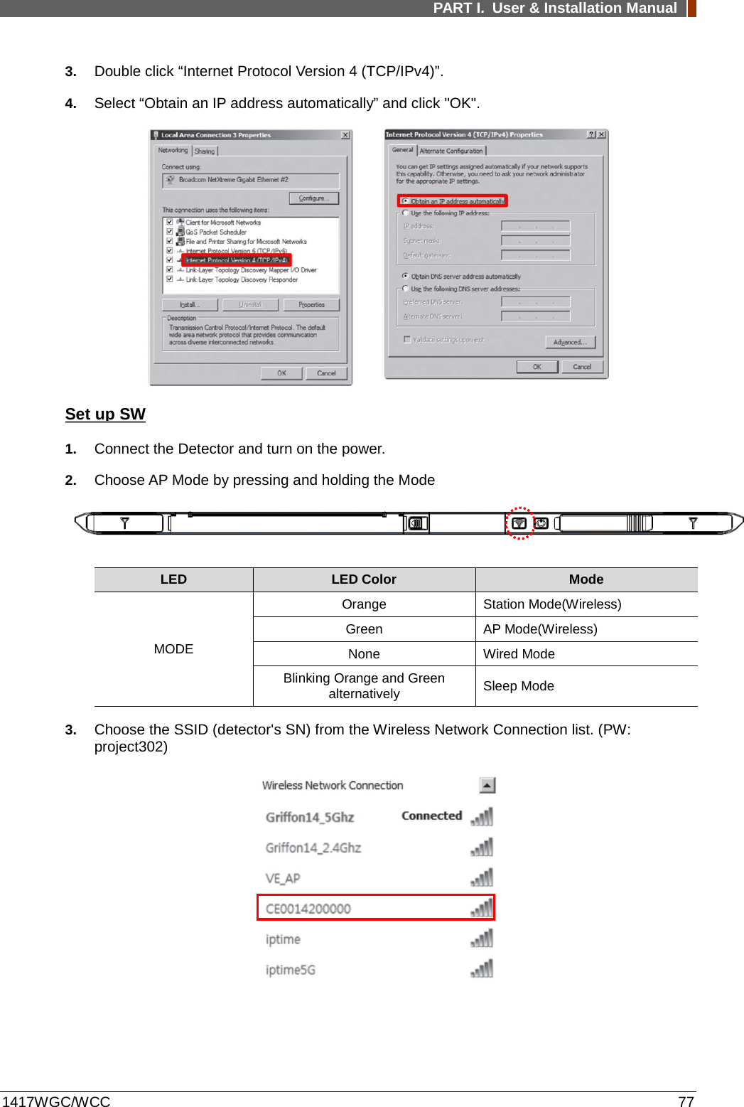
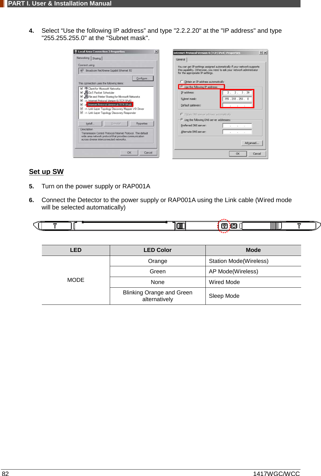
![PART I. User & Installation Manual 56 1417WGC/WCC Set up SW 1. Connect Detector and turn on the power. 2. Choose Station Mode by pressing and holding the Mode Button. LED LED Color Mode MODE Orange Station Mode(Wireless) Green AP Mode(Wireless) None Wired Mode Blinking Orange and Green alternatively Sleep Mode 3. Open “_vadav.lnk” from “C:\davinci”. Once the program is opened and the detector is connected, the LINK LED light from the detector will blink and the Detector Status will display information of the detector as below. Once the correct Sensor IP is put into the Davinci, it will automatically pull the parameter of the connected detector. Model type Parameter Selected 1417WCC [47]1417WCC-R.par 1417WCC_A [69]1417WCC-R_A.par 1417WCC_140 [71]1417WCC-R_140.par 1417WGC [48]1417WGC-R.par 1417WGC_A [70]1417WGC-R_A.par 1417WGC_140 [72]1417WGC-R_140.par](https://usermanual.wiki/Rayence/RYRWM001A.Host-User-Manual-Part-1/User-Guide-3354279-Page-56.png)
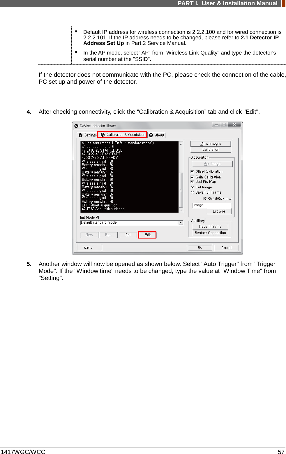
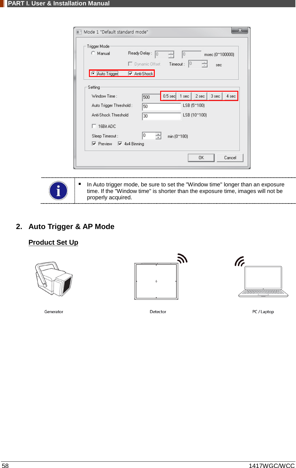
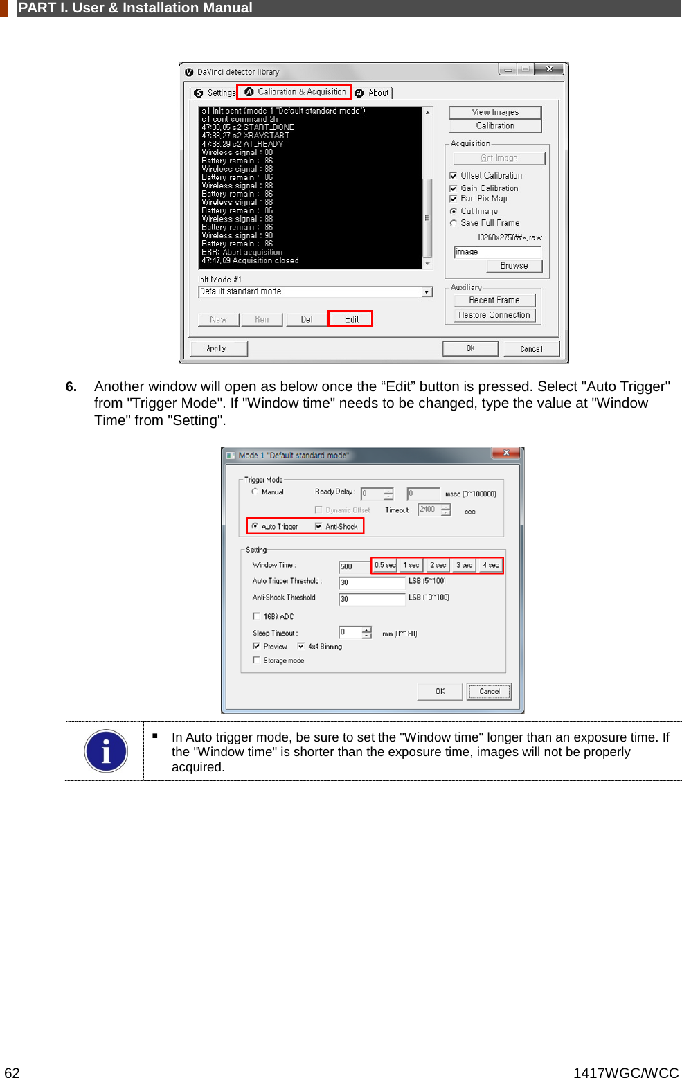
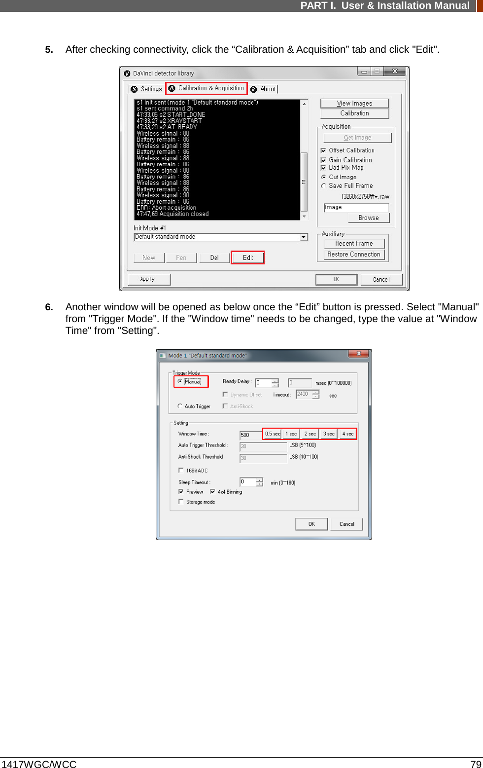
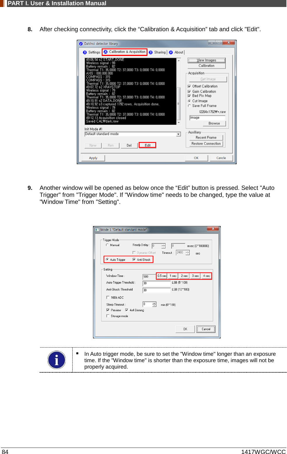
![PART I. User & Installation Manual 1417WGC/WCC 61 Once the correct Sensor IP is put into the Davinci, it will automatically pull the parameter of the connected detector. Model type Parameter Selected 1417WCC [47]1417WCC-R.par 1417WCC_A [69]1417WCC-R_A.par 1417WCC_140 [71]1417WCC-R_140.par 1417WGC [48]1417WGC-R.par 1417WGC_A [70]1417WGC-R_A.par 1417WGC_140 [72]1417WGC-R_140.par Default IP address for wireless connection is 2.2.2.100 and for wired connection is 2.2.2.101. If the IP address needs to be changed, please refer to 2.1 Detector IP Address Set Up in Part.2 Service Manual. In the AP mode, select "AP" from "Wireless Link Quality" and type the detector's serial number at the "SSID". If the detector does not communicate with the PC, please check the connection of the cable, PC set up and power of the detector. 5. After checking connection, click the “Calibration & Acquisition” tab and click "Edit".](https://usermanual.wiki/Rayence/RYRWM001A.Host-User-Manual-Part-1/User-Guide-3354279-Page-61.png)
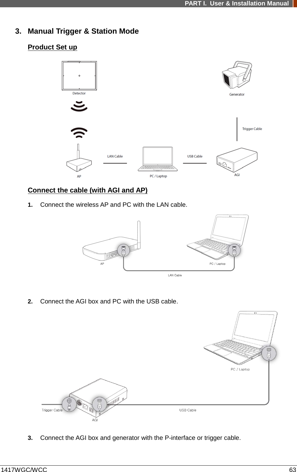

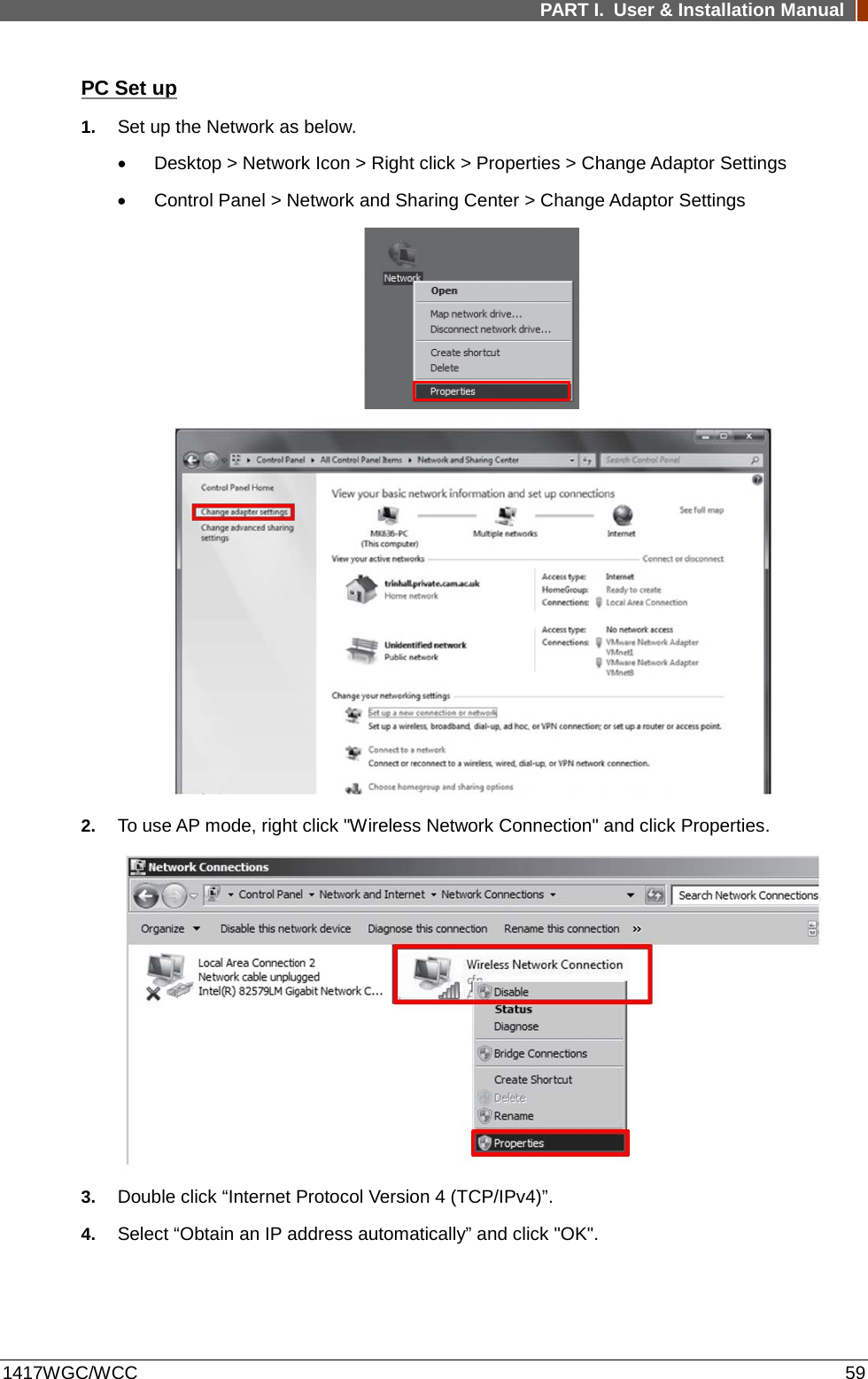
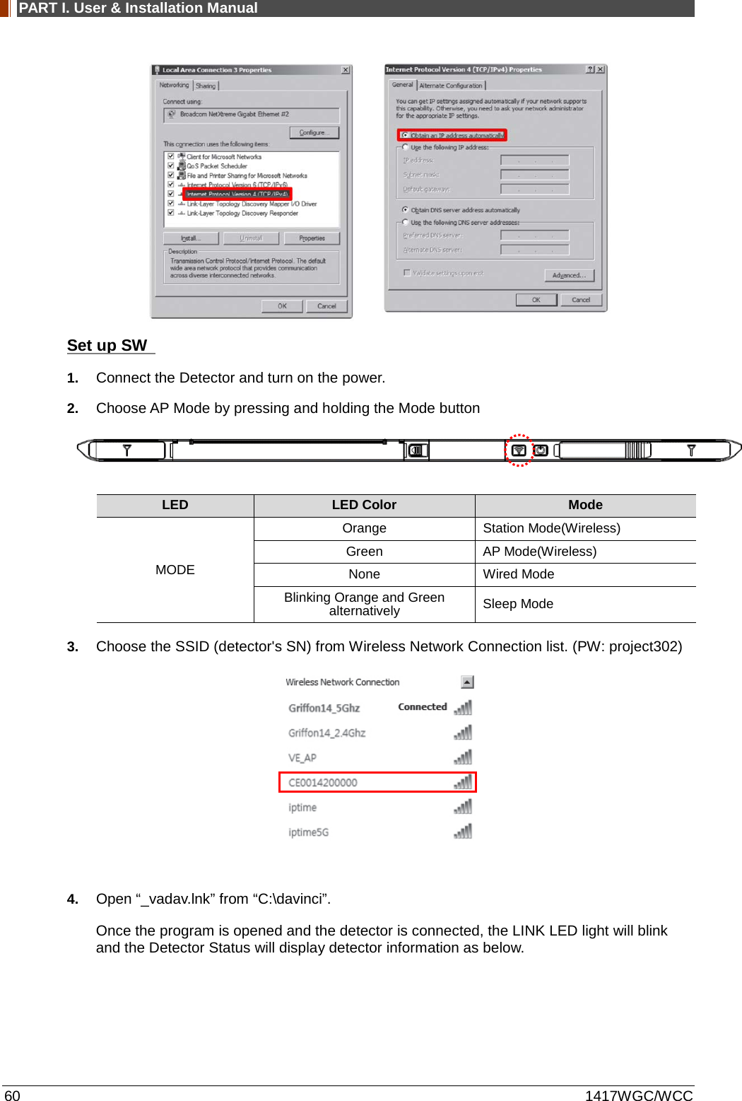
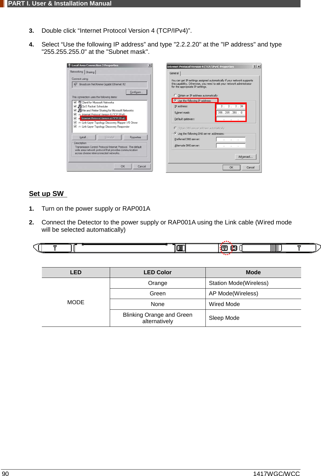
![PART I. User & Installation Manual 1417WGC/WCC 69 Set up SW 1. Connect the Detector and turn on the power. 2. Choose Station Mode by pressing and holding the Mode Button LED LED Color Mode MODE Orange Station Mode(Wireless) Green AP Mode(Wireless) None Wired Mode Blinking Orange and Green alternatively Sleep Mode 3. Open “_vadav.lnk” from “C:\davinci”. Once the program is opened and the detector is connected, the LINK LED light will blink and the Detector Status will display detector information as below. Once the correct Sensor IP is put into the Davinci, it will automatically pull the parameter of the connected detector. Model type Parameter Selected 1417WCC [47]1417WCC-R.par 1417WCC_A [69]1417WCC-R_A.par 1417WCC_140 [71]1417WCC-R_140.par 1417WGC [48]1417WGC-R.par 1417WGC_A [70]1417WGC-R_A.par](https://usermanual.wiki/Rayence/RYRWM001A.Host-User-Manual-Part-1/User-Guide-3354279-Page-69.png)
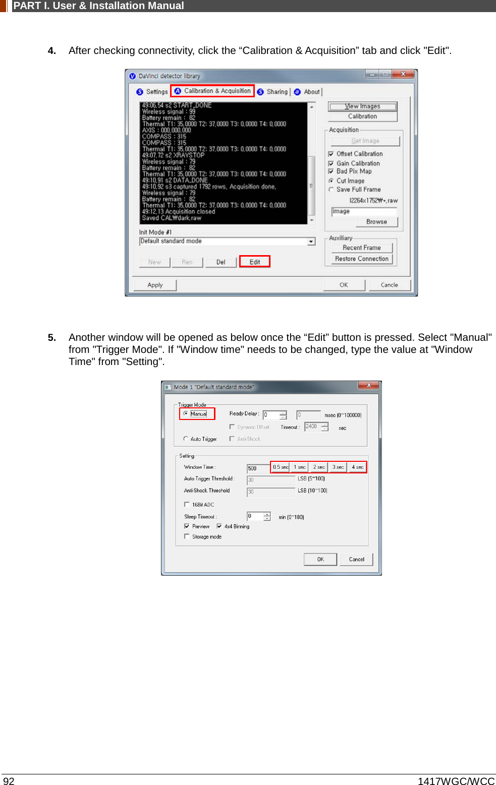
![PART I. User & Installation Manual 70 1417WGC/WCC 1417WGC_140 [72]1417WGC-R_140.par Default IP address for wireless connection is 2.2.2.100 and for wired connection is 2.2.2.101. If the IP address needs to be changed, please refer to 2.1 Detector IP Address Set Up in Part.2 Service Manual. In the AP mode, select "AP" from "Wireless Link Quality" and type the detector's serial number at the "SSID". If the detector does not communicate with the PC, please check the connection of the cable, PC set up and power of the detector. 4. After checking connectivity, click the “Calibration & Acquisition” tab and click "Edit".](https://usermanual.wiki/Rayence/RYRWM001A.Host-User-Manual-Part-1/User-Guide-3354279-Page-70.png)
![PART I. User & Installation Manual 78 1417WGC/WCC 4. Open “_vadav.lnk” from “C:\davinci”. Once the program is opened and the detector is connected, the LINK LED light from the detector will blink and the Detector Status will display panel information as below. Once the correct Sensor IP is put into the Davinci, it will automatically pull the parameter of the connected detector. Model type Parameter Selected 1417WCC [47]1417WCC-R.par 1417WCC_A [69]1417WCC-R_A.par 1417WCC_140 [71]1417WCC-R_140.par 1417WGC [48]1417WGC-R.par 1417WGC_A [70]1417WGC-R_A.par 1417WGC_140 [72]1417WGC-R_140.par Default IP address for wireless connection is 2.2.2.100 and for wired connection is 2.2.2.101. If the IP address needs to be changed, please refer to 2.1 Detector IP Address Set Up in Part.2 Service Manual. In the AP mode, select "AP" from "Wireless Link Quality" and type the detector's serial number at the "SSID". If the detector does not communicate with PC, please check the connection of the cable, PC set up and power of detector.](https://usermanual.wiki/Rayence/RYRWM001A.Host-User-Manual-Part-1/User-Guide-3354279-Page-78.png)
![PART I. User & Installation Manual 1417WGC/WCC 83 7. Open “_vadav.lnk” from “C:\davinci”. Once the program is opened and the detector is connected, the LINK LED light will blink and the Detector Status will display detector information as below. Once the correct Sensor IP is put into the Davinci, it will automatically pull the parameter of the connected detector. Model type Parameter Selected 1417WCC [47]1417WCC-R.par 1417WCC_A [69]1417WCC-R_A.par 1417WCC_140 [71]1417WCC-R_140.par 1417WGC [48]1417WGC-R.par 1417WGC_A [70]1417WGC-R_A.par 1417WGC_140 [72]1417WGC-R_140.par Default IP address for wireless connection is 2.2.2.100 and for wired connection is 2.2.2.101. If the IP address needs to be changed, please refer to 2.1 Detector IP Address Set Up in Part.2 Service Manual. In the AP mode, select "AP" from "Wireless Link Quality" and type the detector's serial number at the "SSID". If the detector does not communicate with the PC, please check the connection of the cable, PC set up and power of the detector.](https://usermanual.wiki/Rayence/RYRWM001A.Host-User-Manual-Part-1/User-Guide-3354279-Page-83.png)
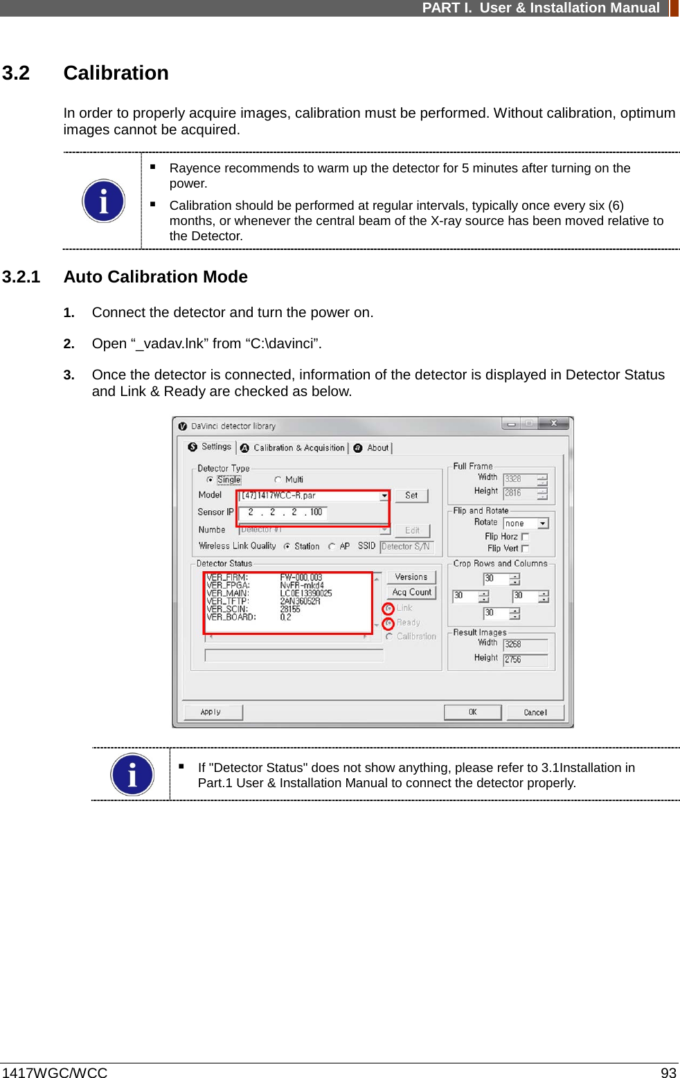
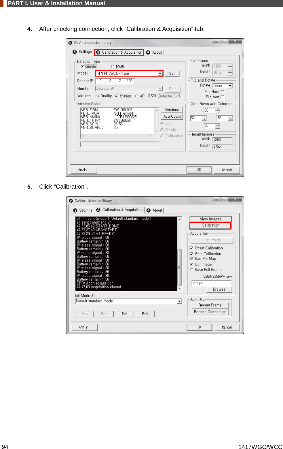
![PART I. User & Installation Manual 1417WGC/WCC 91 3. Open “_vadav.lnk” from “C:\davinci”. Once the program is opened and the detector is connected, the LINK LED light will blink and the Detector Status will display detector information as below. Once the correct Sensor IP is put into the Davinci, it will automatically pull the parameter of the connected detector. Model type Parameter Selected 1417WCC [47]1417WCC-R.par 1417WCC_A [69]1417WCC-R_A.par 1417WCC_140 [71]1417WCC-R_140.par 1417WGC [48]1417WGC-R.par 1417WGC_A [70]1417WGC-R_A.par 1417WGC_140 [72]1417WGC-R_140.par Default IP address for wireless connection is 2.2.2.100 and for wired connection is 2.2.2.101. If the IP address needs to be changed, please refer to 2.1 Detector IP Address Set Up in Part.2 Service Manual. In the AP mode, select "AP" from "Wireless Link Quality" and type the detector's serial number at the "SSID". If the detector does not communicate with the PC, please check the connection of the cable, PC set up and power of the detector.](https://usermanual.wiki/Rayence/RYRWM001A.Host-User-Manual-Part-1/User-Guide-3354279-Page-91.png)