Rayson Technology WFM210 iCOM Smart WiFi Module User Manual WFM210 DataSheet
Rayson Technology Co., Ltd. iCOM Smart WiFi Module WFM210 DataSheet
User manual

aVV
UU
G
1
IEEE 802.11 b/g/n 2.4GHz 1T1R
User Manual
iCOM Smart WiFi Module

aVV
UU
G
2
WFM-210 iAudio(Airplay/DLNA)
(Realtek RTL8196EU+RTL8188ER) Single Module
G
G
G
G
G
G

aVV
UU
G
3
Table of Contents
1. Product Overview-----------------------------------------------------5
1.1. Extended Application-------------------------------------------------5
2. Module Parameter----------------------------------------------------6
2.1. Basic Parameter-------------------------------------------------------6
2.2. Regulation Requirements---------------------------------------------6
2.3. Environment Requirements-------------------------------------------7
2.4. RF Power Consumption-----------------------------------------------7
3. Pin Assignment on module--------------------------------------------8
4. Interface Specifications--------------------------------------------10
5. DVT Report----------------------------------------------------11
6. RF Connector----------------------------------------------------------13
7. Outline Drawing-------------------------------------------------------14
7.1 PCB outline drawing---------------------------------------------------14
7.2 shield cover outline drawing------------------------------------------15

aVV
UU
G
5
1. Product Overview
WFM-210 Serial iAudio(Airplay/DLNA) module is a single chip wireless audio
module that developed by Rayson Technology(Shenzhen) Ltd Company。
WFM-210 Serial Wi-Fi Audio module integrates multiple audio formats such as MP3,
WMA, RA, AAC, WAV, APE, FLAC and Hi-Fi lossless music decoding, maximum decoding
capacity up to 4.5Mbps (24bit/192kHz),the biggest advantage in the ability for loss free
streaming media transmission bandwidth and network。Also can support AIRPLAY
protocol for APPLE device, support DLNA protocol for ANDROID device, support network
media streaming protocol, remote control base on TCP/IP。
WFM-210 Serial Wi-Fi Audio module can also be used for constructing the wireless
network security monitoring, Intelligent wireless audio, wireless intelligent household
appliances。 Support 802.11 b/g/n wireless standard, which can work in wireless AP/STA
mode。For the main Wi-Fi standard 802.11g and 802.11n, the transmission rate is
54Mbps for 802.11g, 150Mbps for 802.11n, all far more than the CD level quality required
bandwidth。At the same time, WFM-210 can realize two device point to point direct, and
also can through Wireless routing network.。
For example, Android smart mobile phone connect to music box through
WFM-210 can achieve shared music between multiple mobile phone, t the same time,
can also satisfy the network multicasting, browsing demand, this is the Bluetooth cannot
does。
WFM-210 Serial Wi-Fi Audio module also support extended interfaces, such as
Ethernet interface support cable internet access, USB interface can access USB extend
storage device。 Support standard UART interface, and can be connected with MCU to
achieve Wi-Fi wireless network control。
1.1 Extended Application
Wireless intelligent audio
Wireless intelligent portable speaker
Wireless intelligent router and music player
tŝƌĞůĞƐƐŚŽŵĞĞŶƚĞƌƚĂŝŶŵĞŶƚĐĞŶƚĞƌ
speaker

aVV
UU
G
6
2. Module Parameter
2.1 Basic Parameter
Feature Detailed Description
Antenna Type IPEX compatible antenna
Main chip RTL8196EU
Frequency range 2.412GHz-2.484GHz
CPU clock 400MHz
DDR1 speed 156.25MHz
DDR1 size 32MB
Flash size 8MB SPI Flash
PCB stack 4 layers
Operating Voltage 3.3VDC +/- 10%
Power Consumption 1.3W@1T1R,
Operation current 136mA~187mA
Form factor Half size Mini-Card 32x27x1 mm
Main Interface 10/100M FE PHY
Network Protocal TCP/IP/UDP/HTTP/UPNP
Network Type AP/STA
Other Interface USB, UART
2.2 Regulation Requirements
Feature Detailed Description
United States IEEE 802.11 b/g/n
FCC part 15.247, 15.205, 15.209
Safety: UL1950-3 for CSA mark
Europe IEEE 802.11 b/g/n
EMC: EN 300 328, EN 300 826, EN 60950
2.412GHz-2.462GHz

aVV
UU
G
7
2.3 Environment Requirements
Feature Detailed Description
Operating
Temperature
Conditions
The product is capable of continuous reliable
operation when operating in ambient temperature
of 0°C to +50°C
Operating
Temperature
Conditions
Neither subassemblies is damaged nor the
operational performance is degraded when restored
to the operating temperature after exposing to
storage temperature in the range of -20°C to +75°C
Operating
Humidity
Conditions
The product is capable of continuous reliable
operation when subjected to relative humidity in the
range of 10% and 90% non-condensing.
Non-Operating
Humidity
Conditions
The product is not damaged nor the performance is
degraded after exposure to relative humidity range
from 5% to 95% non-condensing
2.4 RF Power Consumption
Test Environment :
Platform : Lenovo CPU: Intel i5-3230M @2.6GHz
OS: Win7 32bits Encryption: No encryption
Mode 3.3V Power consumption (mA) Throughput (Mbps)
Non-Associated 2 N/A
Associated Idle 2~116 N/A
Radio off 2 N/A
Disable 2 N/A
Tx n mode 40 MHz 187 93
Rx n mode 40 MHz 155 90.9
Tx n mode 20 MHz 172 48.3
Rx n mode 20 MHz 136 53.7
Tx g mode 173 30.3
Rx g mode 142 29.7
Tx b mode 160 6
Rx b mode 136 6.1

aVV
UU
G
8
3. Pin Assignment on module
Abbreviations in used:
I: Input AI: Analog Input O: Output AO: Analog Output
IO: Bi-Directional Input/Output AI/O: Analog Bi-Directional Input/Output
P: Digital Power G: Digital Ground
PIN NAME TYPE PIN NAME TYPE
1 GND G 52 GND G
2 GPIO_A4 I/O 51 GND G
3 Ethernet_LED O 50 GND G
4 GND G 49 GND G
5 3.3V P 48 GND G
6 3.3V P 47 ANT_A(1T1R_ANT) A
7 3.3V P 46 GND G
8 GND G 45 GND G
9 UARTTRXD I 44 GPIO_0 I/O
10 UARTTTXD O 43 GPIO_4 I/O
11 GND G 42 GPIO_7 I/O
12 TXON AO 41 GND G
13 TXOP AO 40 GND G
14 GND G 39 ANT_B A
15 RXIN AI 38 GND G
16 RXIO AI 37 GND G
17 GND G 36 GND G
18 USB_DN AI/O 35 GND G
19 GND G 34 GND G
20 USB_DP AI/O 33 GND G
21 GND G 32 GND G
22 WLAN_LED O 31 GND G
23 iNIC_RST#/GPIOB5 I/O 30 GND G
24 3.3V P 29 GND G
25 3.3V P 28 GND G
26 GND G 27 GND G

aVV
UU
G
9

aVV
UU
G
10
4.Interface Specifications
1
26
27
52
aVV
UU
G
11
5. DVT Report
Mode:11b Transceiver:A Bandwidth:20MHz Data Rate: 11Mbps
Channel
Pass/Fall Y Y Y Y Y Y Y Y Y Y Y Y Y
Crt
*DLQ6WDJH
'HF2XWSXW
3RZHUG%P
>17
EVM(%)Freq.
Offset(ppm)
<8
±25
[ [ [ [ [ [ [ [ [ [ [ [ [
Thermal
Meter(Hex) 3$66 3$66 3$66 3$66 3$66 3$66 3$66 3$66 3$66 3$66 3$66 3$66 3$66

aVV
UU
G
13
6.RF Connector
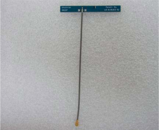
Antenna Information
Antenna Type: PCB Antenna
Antenna Gain: 3.3dBi
Manufacturer: Unictron Technology Corporation
Model Number: AA107
Patent No.: US 8,106,833 B2

aVV
UU
G
14
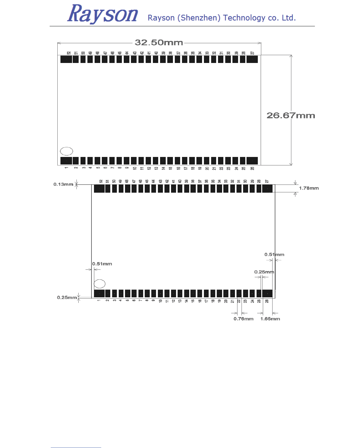
7.Outline Drawing
7.1 PCB outline drawing
aVV
UU
G
15
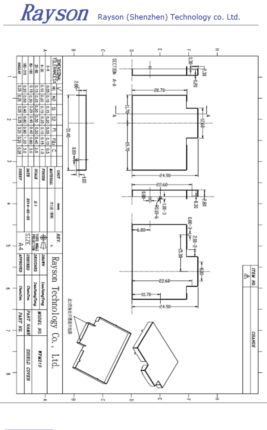
7.2 shield cover outline drawing
This device complies with part 15 of the FCC Rules. Operation is subject to the following two
conditions: (1) This device may not cause harmful interference, and (2) this device must
accept any interference received, including interference that may cause undesired operation.
Changes or modifications not expressly approved by the party responsible for compliance
could void the user's authority to operate the equipment.
FCC Radiation Exposure Statement
The modular can be installed or integrated in mobile or fix devices only. This modular cannot
be installed in any portable device, for example, USB dongle like transmitters is forbidden.
This modular complies with FCC RF radiation exposure limits set forth for an uncontrolled
environment. This transmitter must not be co-located or operating in conjunction with any
other antenna or transmitter. This modular must be installed and operated with a minimum
distance of 20 cm between the radiator and user body.
If the FCC identification number is not visible when the module is installed inside another
device, then the outside of the device into which the module is installed must also display a
label referring to the enclosed module. This exterior label can use wording such as the
following: “Contains Transmitter Module FCC ID: QWOWFM210 Or Contains FCC ID:
QWOWFM210 ā
When the module is installed inside another device, the user manual of this device must
contain below warning statements;
1. This device complies with Part 15 of the FCC Rules. Operation is subject to the following
two conditions:
(1) This device may not cause harmful interference.
(2) This device must accept any interference received, including interference that may cause
undesired operation.
2. Changes or modifications not expressly approved by the party responsible for compliance
could void the user's authority to operate the equipment.
The devices must be installed and used in strict accordance with the manufacturer's
instructions as described in the user documentation that comes with the product