Raytheon IDS M3-VHF-136 110W VHF BASE STATION User Manual P25CCManual1 5
JPS COMMUNICATIONS, INC. 110W VHF BASE STATION P25CCManual1 5
Contents
USERS MANUAL P25CCMANUAL1 THRU 5

System Operator’s User Manual
P25net Channel Controller
Raytheon Company
5800 Departure Drive
Raleigh, NC 27616
24/7 Technical Support
For support, call 1-800-498-3137
Email: p25net.sales@raytheon.com
P/N 5060-600200 Revision 1.05 March, 2011

P25net Channel Controller Operations Manual
2
PROPRIETARY STATEMENT
This document is copyright © Raytheon 2011. No part of this document may be
reproduced in any form, transmitted, or stored in a retrieval system without the
prior written consent of Raytheon.
This document is classified Commercial in Confidence. Its contents may
not be divulged to third parties without the prior written consent of
Raytheon.
The information contained in this manual is the property of Raytheon and is
intended for the purchaser’s use only.
NOTICE
Raytheon reserves the right to make changes to the equipment and specifications
without prior notice.
Raytheon Company
Phone: (919) 790-1011
Fax: (919) 790-1456
5800 Departure Drive
Raleigh, NC 27616

P25net Channel Controller Operations Manual
3
CONTROL AND OWNERSHIP
This is a controlled document. Unless stated otherwise, the sole controlled
copy of this document resides in the Raytheon document control repository, and
other copies in electronic and printed form are uncontrolled.
REVISION HISTORY
Revision Date Details
1.00 03 Jan. 2008 First Release
1.01 24 Jan 2008 Minor updates & formatting; no technical changes
1.03 08 Oct 2008 Added Specifications and Radio Calibration using PCCT
1.04 22 Jan 2009 “Branding” edits to contents
1.05 28 Mar 2011 New product photos, updated interface specification

P25net Channel Controller Operations Manual
4
Table of Contents
1
INTRODUCTION ......................................................................................................................................... 1-1
1.1
Scope .................................................................................................................................................... 1-1
1.2
Description ........................................................................................................................................... 1-1
1.3
Analog Base Radio Requirements ........................................................................................................ 1-2
1.3.1
Duplex Operation ............................................................................................................................ 1-2
1.3.2
Unbalanced Wideband Audio .......................................................................................................... 1-2
1.3.3
PTT/Keyline .................................................................................................................................... 1-2
1.3.4
RSSI ................................................................................................................................................ 1-2
1.3.5
Frequency Stability .......................................................................................................................... 1-3
1.3.6
Narrowband Channel Bandwidth .................................................................................................... 1-3
1.4
Specifications ....................................................................................................................................... 1-3
1.5
Equipment Supplied ............................................................................................................................. 1-4
1.6
Optional Equipment-Not Supplied ....................................................................................................... 1-6
2
INSTALLATION .......................................................................................................................................... 2-1
2.1
General ................................................................................................................................................. 2-1
2.2
Unpacking and Inspection .................................................................................................................... 2-1
2.3
Reshipment of Equipment .................................................................................................................... 2-1
2.4
Installation Overview ........................................................................................................................... 2-2
2.5
Installation Considerations ................................................................................................................... 2-3
2.5.1
Mounting ......................................................................................................................................... 2-3
2.5.2
Cooling ............................................................................................................................................ 2-3
2.5.3
Front Panel Indicators ...................................................................................................................... 2-3
2.5.4
Rear Panel Connectors and Controls ............................................................................................... 2-4
2.6
AC Power Requirements ...................................................................................................................... 2-7
2.7
DC Power Requirements ...................................................................................................................... 2-7
2.8
Network Connection ............................................................................................................................ 2-8
2.9
Radio Interface Connection .................................................................................................................. 2-8
3
RADIO CALIBRATION .............................................................................................................................. 3-1
3.1
Calibration Overview ........................................................................................................................... 3-1
3.2
Equipment Required ............................................................................................................................. 3-1
3.3
Installing PCCT .................................................................................................................................... 3-1
3.4
Configuring PC Network Connection .................................................................................................. 3-3
3.5
Connecting to Channel Cards ............................................................................................................... 3-4
3.6
Updating Firmware .............................................................................................................................. 3-5
3.7
Initialise Mode ..................................................................................................................................... 3-6
3.8
Radio Programming ............................................................................................................................. 3-7
3.9
Transmit Calibration ............................................................................................................................ 3-7
3.9.1
Equipment Set Up............................................................................................................................ 3-7
3.9.2
Initial Steps ...................................................................................................................................... 3-8
3.9.3
Radio Tx Calibration ....................................................................................................................... 3-8
3.10
Rx Calibration .................................................................................................................................... 3-12
3.10.1
Equipment Setup ........................................................................................................................... 3-12
3.10.2
Initial Steps .................................................................................................................................... 3-14
3.10.3
RSSI Calibration ............................................................................................................................ 3-15
3.10.4
Rx Calibration ............................................................................................................................... 3-16
3.10.5
Sync Calibration ............................................................................................................................ 3-19
3.11
Load/Save Transceiver Configuration ................................................................................................ 3-20

P25net Channel Controller Operations Manual
5
3.11.1
Load/Save Config Window ........................................................................................................... 3-20
3.11.2
Default Radio Settings Loaded...................................................................................................... 3-21
3.12
Fallback Mode ................................................................................................................................... 3-21
List of Figures
FIGURE 1-1 TYPICAL P25NET SYSTEM ..................................................................................................................... 1-2
FIGURE 2-1 P25NET CC OUTLINE DIMENSIONS ...................................................................................................... 2-6
FIGURE 2-2 FRONT PANEL (4 CHANNEL UNIT SHOWN) ........................................................................................... 2-6
FIGURE 2-3 REAR PANEL (4 CHANNEL UNIT SHOWN) ............................................................................................. 2-7
FIGURE 2-4 AC ADAPTER ....................................................................................................................................... 2-7
FIGURE 3-1: COMMENCING INSTALLATION OF THE PCCT APPLICATION ................................................................. 3-2
FIGURE 3-2: INSTALLATION OF THE PCCT APPLICATION COMPLETED ..................................................................... 3-2
FIGURE 3-3 PCCT ICON ........................................................................................................................................... 3-3
FIGURE 3-4 PC LOCAL AREA NETWORK SETTING ................................................................................................... 3-4
FIGURE 3-5 CONNECTION DIALOG BOX ................................................................................................................... 3-5
FIGURE 3-6 FIRMWARE UPDATE WINDOW ............................................................................................................... 3-5
FIGURE 3-7 INITIALISE MODE WINDOW ................................................................................................................... 3-6
FIGURE 3-8 TX CALIBRATION SETUP ...................................................................................................................... 3-7
FIGURE 3-9 CONFIGURE TX WINDOW ..................................................................................................................... 3-8
FIGURE 3-10 TEST SET OSCILLOSCOPE: DEMODULATED AUDIO ............................................................................. 3-9
FIGURE 3-11 TEST SET OSCILLOSCOPE: SHORT SQUARE WAVE ........................................................................... 3-10
FIGURE 3-12 TEST SET OSCILLOSCOPE: SINE WAVE ............................................................................................. 3-11
FIGURE 3-13 CONFIGURE TX WINDOW: MINUS SIGN FOR TX VCO GAIN .............................................................. 3-12
FIGURE 3-14 RX CALIBRATION SET-UP ................................................................................................................. 3-13
FIGURE 3-15 CONFIGURE TX AND RX (MANUAL) WINDOW .................................................................................. 3-14
FIGURE 3-16 RSSI LOW LEVEL ............................................................................................................................. 3-15
FIGURE 3-17 RSSI HIGH LEVEL ............................................................................................................................ 3-16
FIGURE 3-18 RX GAIN AND OFFSET ADJUSTMENT ................................................................................................ 3-17
FIGURE 3-19 CONFIGURE RX AUTOMATIC: RSSI TRIGGER ................................................................................... 3-18
FIGURE 3-20 CONFIGURE RX (AUTOMATIC): FIND SYNC ....................................................................................... 3-19
FIGURE 3-21 LOAD/SAVE CONFIG SCREEN ........................................................................................................... 3-20
FIGURE 3-22 DEFAULT SETTINGS APPLIED SCREEN .............................................................................................. 3-21
FIGURE 3-23 FALLBACK MODE ENABLE SCREEN .................................................................................................. 3-22
List of Tables
TABLE 1-1 P25NET CC SPECIFICATIONS ................................................................................................................ 1-3
TABLE 1-2 EQUIPMENT AND ACCESSORIES SUPPLIED ............................................................................................. 1-5
TABLE 1-3 EQUIPMENT AND ACCESSORIES SUPPLIED ............................................................................................. 1-5
TABLE 1-4 EQUIPMENT AND ACCESSORIES SUPPLIED ............................................................................................. 1-5
TABLE 1-5 EQUIPMENT AND ACCESSORIES SUPPLIED ............................................................................................. 1-6
TABLE 1-6 OPTIONAL EQUIPMENT - NOT SUPPLIED ................................................................................................ 1-6
TABLE 2-1 D15F CONNECTOR PIN-OUTS (CHANNELS 1-4) ..................................................................................... 2-5
P25net Channel Controller Operations Manual
6
Glossary
APCO Association of Public-Safety Communications Officials. Note
that in this document, “APCO” as used invariably refers to APCO
Project 25
APCO P25 APCO Project 25 digital conventional and trunked radio standard.
BS Base Station
BSC Base Station Controller
CC See P25net CC.
IP Internet Protocol
ISSI Inter Subsystem Interface
OTAR Over The Air Rekeying
P25 P25 See APCO P25.
P25net Raytheon APCO 25 network solution
P25net CC P25 Channel Controller
PSTN Public Switched Telephone Network
RF RF Radio Frequency
RFSS RFSS RF Subsystem
RSSI RSSI Received Signal Strength Indicator
Rx or RX Receive
Tx or TX Transmit
WACN Wide-Area Communications Network
P25net Channel Controller Operations Manual
1-1
1 Introduction
1.1 Scope
This instruction manual provides information necessary to install and operate the P25net
Channel Controller, a component of Raytheon’s P25net system. Installation requirements and
calibration with the connected radio are covered. For system installation, configuration, and
operation refer to the P25net Training Guide.
1.2 Description
The P25net Channel Controller (P25net CC) is a 1 RU (Rack Unit; 1.75”) device designed to
allow legacy analog repeaters the ability to remain in service and become digital P25 capable.
By attaching a P25net CC to existing analog repeaters, all aspects of the P25 Common Air
Interface (CAI) can be achieved including conventional, trunked, data, and over the air
rekeying (OTAR).
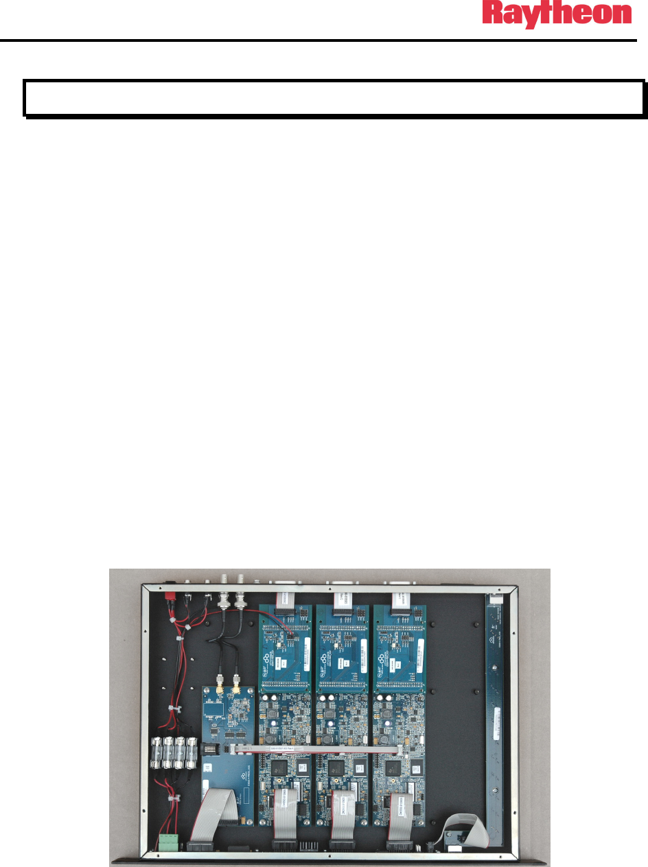
The P25net CC consists of up to four channel cards per chassis, each using the P25 protocol
stack. Each channel card connects to a new or existing analog repeater to provide digital P25
signaling capabilities. The P25net CC functions as a Conventional 4 Level Frequency
Modulation (C4FM) modulator/demodulator for the repeater to encode and decode digital
audio for transmission and reception. The channel card processor can repeat these signals
locally over the connected repeater or establish a connection over an IP network to a distant
repeater or network.
Figure 1-1 P25netCC Internal Layout (3 Channel Unit Shown)
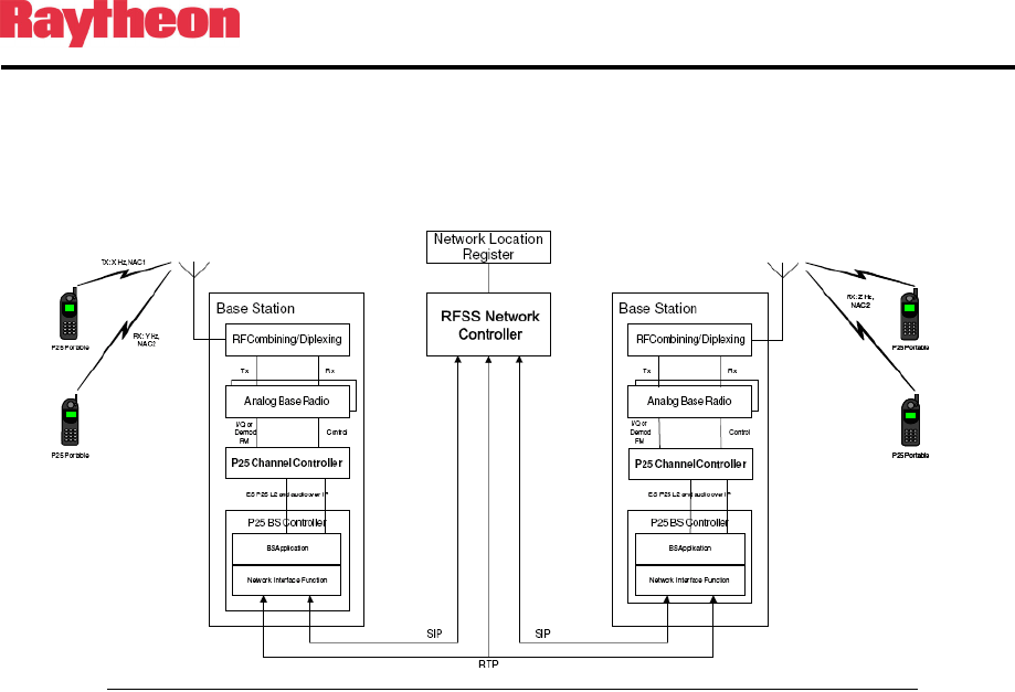
Typically, the P25net CC is connected to multiple repeaters to provide several channels and to
a Base Station Controller (BSC) which provides site control functionality (see Figure 1-2). By
P25net Channel Controller Operations Manual
1-2
combining two or more P25net sites with a Radio Network Controller (RNC) and a Network
Location Register (NLR) through an IP based network, a multi site system can be created.
Figure 1-2 Typical P25net System
1.3 Analog Base Radio Requirements
The following are general considerations for radios suitable for P25net CC interface
requirements.
1.3.1 Duplex Operation
The radio must be capable of full duplex operation as a base station rather than a repeater. This
is necessary because the P25net CC must control the repeat function.
1.3.2 Unbalanced Wideband Audio
Unbalanced Tx and Rx wideband audio without pre-emphasis and de-emphasis is required to
pass the 0-3000Hz baseband necessary for P25 signals. DC coupling is preferred since it
provides the best low frequency response. The capability to turn off all filters is recommended.
“Balanced Line Audio” means that transformers are in the signal path and will limit low
frequency response.
1.3.3 PTT/Keyline
The P25net CC provides an open collector for grounding the radio PTT/Keyline to
transmit.
1.3.4 RSSI
The P25net CC uses the Receive Signal Strength Indicator (RSSI) signal in determining
validity of a received P25 signal.
P25net Channel Controller Operations Manual
1-3
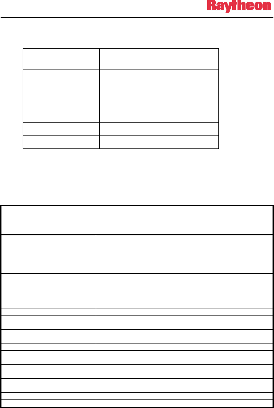
1.3.5 Frequency Stability
The following recommendations are from the P25 standard (ANSI/TIA-102.CAAB-C):
Assigned Frequency
(MHz)
Frequency Stability Parts per
Million (PPM)
Below 100 2.5
138-174 1.5
406-512 0.5
764-806 0.1
806-869 0.15
896-941 0.1
1.3.6 Narrowband Channel Bandwidth
The radio should be capable of 12.5kHz channel programming.
1.4 Specifications
Table 1-1 P25net CC Specifications
Power
AC Power Input 90-264VAC, 47-63Hz, 20VA from external AC adapters (supplied) for
connection to DC Inputs A and B (J1and J2 on rear panel). J1/J2 are
5.5mm x 2.5mm locking DC Power Jacks (Switchcraft L712A; mating
plug Switchcraft 761K).
DC Power Inputs A and B +11.0-13.2VDC 1A for connection to J1and J2 on rear panel; J1/J2 are
5.5mm x 2.5mm locking DC Power Jacks (Switchcraft L712A; mating
plug Switchcraft 761K).
Dual Power Source DC inputs A and B allow connection of 2 power sources for added
reliability.
Signal Inputs
Receive Baseband Audio Pin 7 on the D15F rear panel connector Channels 1-4;
0-3000Hz, 3vpp (1.06 vrms) maximum
RSSI Pin 8on the D15F rear panel connector Channels 1-4;
Receive Strength Signal Indicator (RSSI) signal from radio; 0-5VDC.
Signal Outputs
Transmit Baseband Signal Pin 6 on the D15F rear panel connector Channel 1-4
0-3000Hz, 3vpp (1.06vrms) maximum
PTT or Keyline Pin 5 on the D15F rear panel connector Channel 1-4
Open Collector, active low
Analog Ground Pins 14,15 on the D15F rear panel connector Channel 1-4
Ground reference for the input/output signals
Data Connections
IP Connection RJ45 connectors on the front and rear panel.

P25net Channel Controller Operations Manual
1-4
Table 1-1 P25net CC Specifications
RS-232 Receive RS-232 Rx: Pin 1 on the D15F rear panel connector Channel 1-4
RS-232 Transmit RS-232 Tx: Pin 2 on the D15F rear panel connector Channel 1-4
Digital Ground Pin 9 on the D15F rear panel connector Channel 1-4
Ground reference for the RS-232 data lines.
Programmable I/O
DIN0 Programmable Input 0 (reserved) Pin 10 on the D15F rear panel
connector Channel 1-4
DIN1 Programmable Input 1 (reserved) Pin 3 on the D15F rear panel
connector Channel 1-4
DIN2 Programmable Input 2 (reserved) Pin 12 on the D15F rear panel
connector Channel 1-4
OUT0 Programmable Output 0 (reserved) Pin 4 on the D15F rear panel
connector Channel 1-4
IN3 Programmable Input 13 (reserved) Pin 3 on the D15F rear panel
connector Channel 1-4
FGND Ground reference for IN3
LED Display
S1 Green when 10MHz GPS Reference connected
DC Power A and B Green when DC power is at DC Inputs A and B
Channel Status For each supplied channel: Steady Green when controlled by BSC;
flashing otherwise.
Rx For each supplied channel: Orange when a valid P25 signal is received.
Tx For each supplied channel: Red when a signal is being transmitted
Physical
Size 1.75” H x 19” W x 12.4” D (4.4 x 48.3 x 31.5 cm).
Weight 5 pounds ( 2.3kg)
Operating Temperature 0 to +60 degrees C.
Storage Temperature -40 to +85 degrees C.
1.5 Equipment Supplied
Table 1-2 Equipment and Accessories Supplied
P25net CC Top Level Part Number Explanation
5060- 6 X 0 2 X 0
P25net
Family
# of Channels 1=Standard I/O
1=1 Channel 2=4 Wire AFSI
2=2 Channel
3=3 Channel
4=4 Channel
All units include:

P25net Channel Controller Operations Manual
1-5
1 P25net CC Operation Manual 5060-600200
1 Accessory Kit consisting of: 5060-610150
(2 )AC Power Supply 90-264VAC 1620-264061
(2) Line Cord 0313-037770
Table 1-3 Equipment and Accessories Supplied
P25net CC with Manual and Accessory Kit
All items below are included within P/N 5060-610000
Items included: 1 P25NET CC One Channel Unit 5060-610500
1 Operation Manual 5060-612000
1 Accessory Kit- Consisting of: 5960-610150
Qty Part Number Description
2 0313-037770 Line Cord
2 1620-264061 Power Supply, 90-264VAC
Table 1-4 Equipment and Accessories Supplied
P25net CC Two Channel Unit with Manual and Accessory Kit
Quantity Item P/N
1 P25net CC Two Channel Unit with Manual and Accessory Kit 5060-620000
All items below are included within P/N 5060-610000
Items included: 1 P25net CC One Channel Unit 5060-610000
1 P25net CC One Channel Expansion Kit 5060-650000
1 Operation Manual 5060-612000
1 Accessory Kit- Consisting of: 5960-610150
Qty Part Number Description
2 0313-037770 Line Cord
2 1620-264061 Power Supply, 90-264VAC
Table 1-5 Equipment and Accessories Supplied
P25NET CC Three Channel Unit with Manual and Accessory Kit
Quantity Item P/N
1 P25net CC Three Channel Unit with Manual and Accessory Kit 5060-630000
All items below are included within P/N 5060-620000
Items included: 1 P25net CC One Channel Unit 5060-610000
2 P25net CC One Channel Expansion Kit 5060-650000
1 Operation Manual 5060-612000
1 Accessory Kit- Consisting of: 5960-610150
Qty Part Number Description
P25net Channel Controller Operations Manual
1-6
Table 1-5 Equipment and Accessories Supplied
2 0313-037770 Line Cord
2 1620-264061 Power Supply, 90-264VAC
Table 1-6 Equipment and Accessories Supplied
P25NET CC Four Channel Unit with Manual and Accessory Kit
Quantity Item P/N
1 P25net CC Four Channel Unit with Manual and Accessory Kit 5060-640000
All items below are included within P/N 5060-620000
Items included: 1 P25net CC One Channel Unit 5060-610000
3 P25net CC One Channel Expansion Kit 5060-650000
1 Operation Manual 5060-612000
1 Accessory Kit- Consisting of: 5960-610150
Qty Part Number Description
2 0313-037770 Line Cord
2 1620-264061 Power Supply, 90-264VAC
1.6 Optional Equipment-Not Supplied
Table 1-7 Optional Equipment - Not Supplied
Item P/N
P25net CC Single Channel Standard I/O Expansion Kit
For adding an additional channel to the P25net CC
5060-652000
P25net CC Single Channel 4W AFSI
End of Section 1

P25net Channel Controller Operations Manual
2-1
2 Installation
2.1 General
This section provides the instructions for unpacking, inspection, installation and set-up.
Included are directions for reshipment of damaged parts or equipment.
2.2 Unpacking and Inspection
After unpacking the unit, retain the carton and packing materials until the contents have been
inspected and checked against the packing list. If there is a shortage or any evidence of damage,
do not attempt to use the equipment. Contact the carrier and file a shipment damage claim. A
full report of the damage should be reported to the Raytheon’s customer service department.
The following information should be included in the report:
1. Order Number
2. Equipment Model and Serial Numbers
3. Shipping Agency
4. Date(s) of Shipment
The Raytheon customer service department can be reached by phone at (919) 790-1011, or by
fax at (919) 790-1456. Upon receipt of this information, Raytheon will arrange for repair or
replacement of the equipment.
2.3 Reshipment of Equipment
If it is necessary to return the equipment to the manufacturer, a Returned Material
Authorization (RMA) number must first be obtained from Raytheon. This number must be
noted on the outside of the packing carton and on all accompanying documents. When packing
the unit for reshipment, it is best to use the original packaging for the unit; if this is not
possible, special attention should be given to providing adequate packing material around
connectors and other protrusions, such as front panel ears. Rigid cardboard should be placed at
the corners of the unit to protect against corner damage during shipment. Failure to protect the
corners of the front panel causes the most common type of shipping damage experienced on
returned equipment.

P25net Channel Controller Operations Manual
2-2
Shipment should be made prepaid consigned to:
Raytheon Company
Customer Service Department
5800 Departure Drive
Raleigh, North Carolina 27616
USA
Plainly, mark with indelible ink all mailing documents as follows:
U.S. GOODS RETURNED FOR REPAIR
Mark all sides of the package:
FRAGILE - ELECTRONIC EQUIPMENT
Inspect the package prior to shipment to be sure it is properly marked and securely wrapped.
2.4 Installation Overview
Four steps are needed to properly install the P25net CC. These steps are:
1. Provide mechanical mounting for the unit. See Section 2.5 for instructions regarding air
circulation requirements and other mechanical mounting considerations.
2. Provide the proper primary power for the unit; see Section 2.6 and 2.7.
3. Interconnect the unit with the communications system via the unit's rear panel
connectors; see Sections 2.8 and 2.9
4. Calibrate the radio to the P25net CC using Personal Computer Calibration Tool (PCCT)
as covered in Section 3.

P25net Channel Controller Operations Manual
2-3
2.5 Installation Considerations
Careful attention to the following installation suggestions should result in the best unit/system
performance. Figure 2-1 provides overall unit dimensions.
The P25net CC must be installed in a structure, which provides both protection from the
weather and assurance of ambient temperatures between -0 and +60 degrees C. Since the unit
is neither splash proof, nor corrosion resistant, it must be protected from exposure to salt spray.
When the unit is mounted in a cabinet with other heat-generating equipment, the use of a rack
blower is suggested to keep the cabinet interior temperature rise to a minimum.
2.5.1 Mounting
For applications such as mobile command centers or transportable cases or any other
application where some degree of shock and vibration is expected, the P25net CC must be
mounted with support brackets in addition to the front mounting screws. For fixed applications
such as floor mounted cabinets or racks in a fixed equipment room, rear supports are not
required.
2.5.2 Cooling
The P25net CC depends on natural convection for its cooling. It must be mounted in a way that
allows for sufficient air circulation to keep the ambient temperature around the unit from
exceeding +60C. Use forced air-cooling in the cabinet if necessary. The P25net CC generates
approximately 50 BTU/Hr heat.
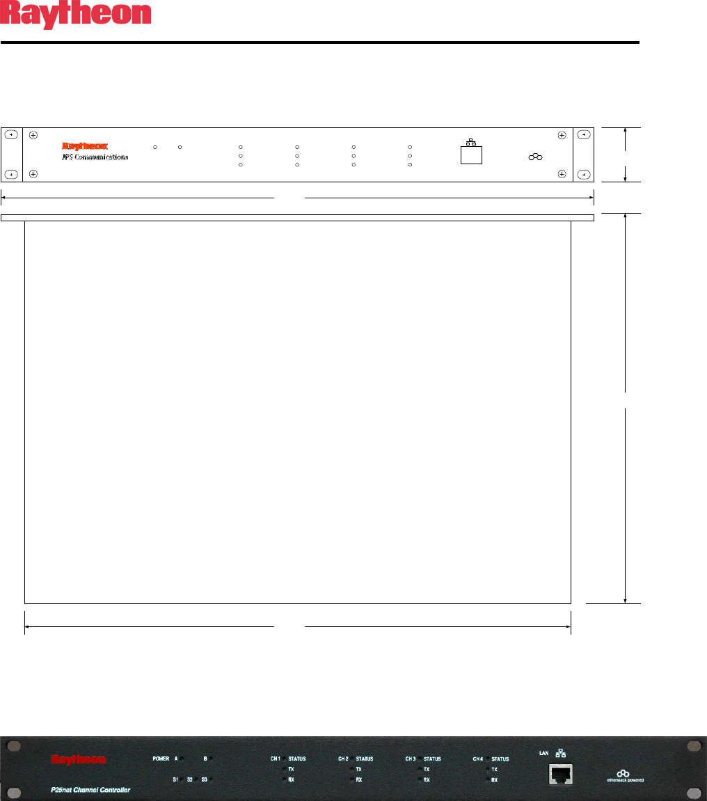
2.5.3 Front Panel Indicators
INDICATOR DESCRIPTION
Power A Power Source A is present
Power B Power Source B is present
S1 Green when 10MHz GPS Reference
connected at rear panel input
S2 Future use
S3 Future use
Channel Status Green when channel is under BSC
control; flashing otherwise (Fallback
Mode)
Tx Red when channel is transmitting;
also will indicate during a firmware
update procedure and at power on or
software reset.
Rx Orange when channel receives a
valid P25 signal; also will indicate
during a firmware update procedure
and at power on or software reset.

P25net Channel Controller Operations Manual
2-4
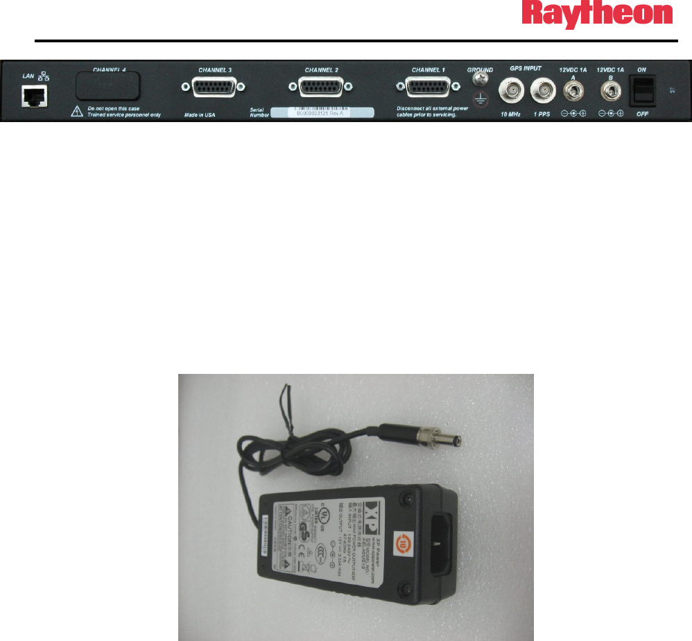
2.5.4 Rear Panel Connectors and Controls
2.5.4.1 D15 Radio Interface Connector
The rear panel has up to four D15 connectors for interface to radios. The pin-outs for each connector
channel are listed in the following table. Units having less than 4 channels will have unused connector
locations covered with a press-in type plug.

P25net Channel Controller Operations Manual
2-5
Table 2-1 D15F Connector Pin-outs (Channels 1-4)
Pin Function
1 RS232_RX_IN
2 RS232_ TX1_OUT
3 DIN1
4 OUT0
5 TXKEY
6 AUDIO_TX_OUT
7 AUDIO_RX_IN
8 RSSI_OUT
9 DGND
10 DIN0
11 FGND
12 DIN2
13 IN3
14 AGND
15 AGND
2.5.4.2 DC Input Jack J1,J2
The supplied external AC adapters connect to DC inputs A and B (J1/J2 on rear panel; J1/J2 are
5.5mm x 2.5mm locking DC Power Jacks (Switchcraft L712A). The adapters are terminated
with a mating locking plug (Switchcraft 761K).
2.5.4.3 GPS Reference Input
BNC(F) connectors for 10MHz and 1PPS signals are provided for Simulcast operation.
2.5.4.4 Power Switch S1
S1 switches both power sources.
P25net Channel Controller Operations Manual
2-6
2.5.4.5 RJ45 Ethernet port
This jack is normally used for connection to a BSC
.
P25 Channel Controller
LAN
AC power DC power channel 1 processor
tx
rx
channel 2 processor
tx
rx
channel 3 processor
tx
rx
channel 4 processor
tx
rx
etherstack powered
1.75
12.4
16.75
19.0
Figure 2-1 P25net CC Outline Dimensions
Figure 2-2 Front Panel
P25net Channel Controller Operations Manual
2-7
Figure 2-3 Rear Panel (3 Channel Unit shown)
2.6 AC Power Requirements
The P25net CC is supplied with two AC adapters (Figure 5) that will operate over a wide AC
voltage range (90-264VAC). The supply circuit requirement is 20VA. The adapters are
provided with locking DC plugs for connection to the P25net CC rear panel DC input jacks A
and B. The adapters supply 12VDC @ 1A to the P25net CC. Each has an IEC 320 inlet for
attaching the AC power cord (supplied).
Figure 2-4 AC Adapter
2.7 DC Power Requirements
The P25net CC will operate on +11.0 to +13.2VDC @ 1A when connected to DC Inputs A/B.
Removal of one source will have no effect on the P25net CC when running from both sources.
The front panel power LED will indicate when a source is connected and the power switch is
ON.

P25net Channel Controller Operations Manual
2-8
2.8 Network Connection
The P25net CC must be connected by a single Cat-5 or Cat-6 cable to either an Ethernet switch
or hub, or connected directly to a Base Station Controller (BSC). Either the front or rear RJ-45
connector can be used for this purpose, but both connectors should not be cabled to the same
device.
It is preferable to use the rear RJ-45 connector for connecting the P25net CC to a BSC, if they
are linked directly without a local Ethernet switch or hub. This leaves the front RJ-45 connector
free for connecting a PC for radio calibration or firmware updates.
2.9 Radio Interface Connection
Systems engineers at Raytheon have created interface cables and accompanying Application
Notes for a number of radios. The cables are shielded and terminated with connectors for easy
connection between the radio and P25net CC rear panel.
The application notes provide the cable schematic as well as programming and set-up
recommendations for the specific radio.
End of Section 2

P25net Channel Controller Operations Manual
2-9
This Page Intentionally Left Blank

P25net Channel Controller Operations Manual
3-1
3 Radio Calibration
3.1 Calibration Overview
The channel card in the P25net CC must be calibrated to the connected radio. This process
adjusts the internal audio circuits within the P25net CC to adapt to the radio’s audio levels and
sets the transmit deviation for P25 narrowband requirements. In addition, the RSSI signal from
the receiver is characterized by the P25 processor to enable proper synchronization to the P25
packet data streams.
Each transceiver radio has different physical components from other types of transceivers and
even from other transceivers of the same make and model. Because of this, each transceiver
channel in the P25net CC has to be tuned to ensure an optimal receiver and transmit signal are
produced. This is a critical step and if not performed will render the channel partially or
completely incapable of P25 operation.
PC Tools (PCCT) is an application that runs on a pc and provides the necessary controls to
perform the calibration. PCCT also allows setting various operational parameters (such as
Fallback Mode) and performing testing. See Chapter 4 for PCCT advanced features.
3.2 Equipment Required
• PCCT Running on a PC (preferably a Laptop)
• CAT 5 LAN cable
• RF Test Set (preferably with APCO 25 test capability) such as the Aeroflex
3920 as used in the following example
• A pair of conventional P25 portable radios (handsets) with programming
software and cable to allow programming to the base radio channel.
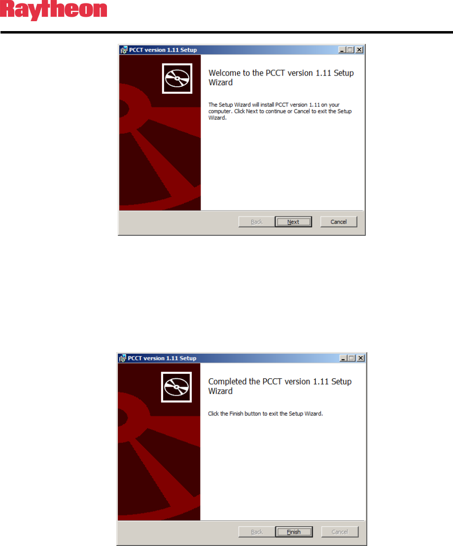
3.3 Installing PCCT
The PCCT application is installed by running the Windows installer package PCCTSetup.msi.
If this file does not run automatically from a supplied CD, find this file and execute it. The
initial splash screen as shown below will then be presented to the user. As with most of these
dialog boxes presented during the installation process the “Next” button moves to the next
stage of the installation and the “Back” button returns to the previous dialog box.
P25net Channel Controller Operations Manual
3-2
Figure 3-1: Commencing installation of the PCCT Application
During the installation process, the user will be prompted to accept the End-User License
Agreement (required in order to proceed with installation), select a destination folder for the
PCCT application (C:\Program Files\Etherstack\PCCT x.xx, by default), after which
installation will commence.
When installation is complete, the following message will be shown:
Figure 3-2: Installation of the PCCT application completed
The PCCT is then ready to use, and may be launched using the shortcut installed on the
desktop:

P25net Channel Controller Operations Manual
3-3
Figure 3-3 PCCT Icon
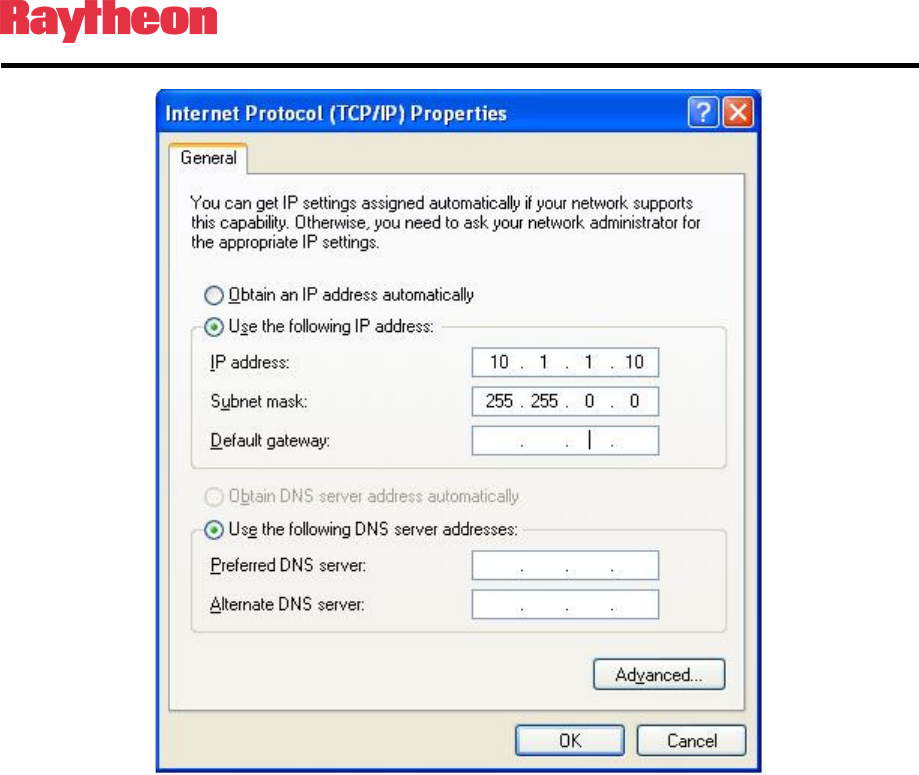
3.4 Configuring PC Network Connection
The PC must be configured to set the Local Network connection to the same address range as
the Channel Card. See Figure 3-4. Typically this is done by selecting:
Control Panel>Network Connections>Local Area Connections>Properties.
Then scroll to Internet Protocol (TCP/IP) and Click on Properties; Select “Use the Following
Address” and enter the IP address and Subnet mask to correspond to the requirement of the
Channel card address.
Assuming a default channel card address of 10.1.1.1 with a subnet mask of 255.255.0.0, this
would require the PC to be set within the same net with a different address, for example
10.1.1.10 (the PC can’t have the same address as the Channel card).
P25net Channel Controller Operations Manual
3-4
Figure 3-4 PC Local Area Network Setting
3.5 Connecting to Channel Cards
A standard Cat 5 LAN cable should be connected from the PC to the P25net CC front panel
RJ45 jack.
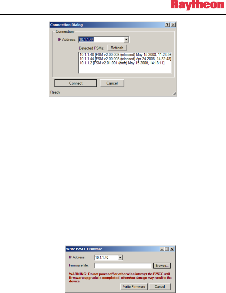
The ‘Open Connection’ item in the ‘File’ menu allows a specific IP address to be used for
connecting to a single Channel Card, and also contains a list of auto-detected Channel Cards on
the local network. This list is populated by sending out a broadcast to the network, to which
Channel Cards respond.
P25net Channel Controller Operations Manual
3-5
Figure 3-5 Connection Dialog Box
To connect to the Channel Card at a specific IP address, type its address in the text field, and
click ‘Connect’. Alternatively, double click the address in the list of auto-detected Channel
Cards. Following connection, the oscilloscope window will now be visible, and the
configuration interface is now ready for use.
A list of recently used IP addresses is stored, and is available by clicking the down arrow in the
IP Address field.
Connection of the PCCT to the Channel Cards requires the Channel Cards to be located on the
same subnet as the computer running the PCCT. If connection to a card fails, verify that this is
the case.
It is possible to use the PCCT to communicate with all 4 cards, by using the Connection dialog
to connect to each of them in turn. A new tab will be created for each card that the P25net CC
connects to successfully.
3.6 Updating Firmware
The user can update the firmware on the Controller Card by selecting ‘Write P25net CC
Firmware’ from the ‘Options’ menu. This will open the following window Figure 3-6:
Figure 3-6 Firmware Update Window
Enter the IP address of the Controller Card whose firmware is to be updated, then select the file
containing the firmware image. Click the ‘Write Firmware’ button’. A window will appear
indicating that the firmware update is in progress, and once the update is complete (duration <
30sec) a confirmation message will indicate success of the update.
P25net Channel Controller Operations Manual
3-6
At the end of the firmware process, the front panel lights for that channel will alternate then
both stay on and then only the single processor LED should remain lit.
IMPORTANT NOTE: Do not switch off the power or interrupt the connection between the
PCCT and P25net CC during firmware updates. Wait until the single Processor LED
remains lit before any other action.
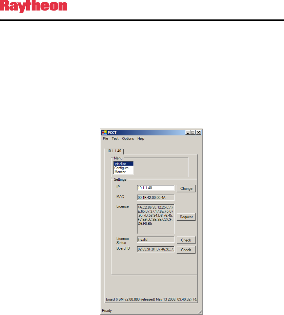
3.7 Initialise Mode
In this mode, the user can examine and modify the current IP address of the Controller Card.
The user can also examine the MAC address, license key, license status (Valid or Invalid), and
board identifier of the Controller Card.
Figure 3-7 Initialise Mode Window
By default, the MAC address and license key are not user-editable. They can be edited by
enabling ‘Allow MAC/License Key Editing’ from the Options menu. Note that each board
should have a unique MAC from all other boards ever used and each IP should be distinct for
all boards that will be connected to a single BSC.
IMPORTANT NOTE: Be careful when modifying the IP address. Setting an invalid address
will not allow the PCCT to communicate with it. Also, make sure duplicate addresses are not
used (such as two or more Channel Cards having the same address)
P25net Channel Controller Operations Manual
3-7
3.8 Radio Programming
The radio should be programmed according to the Application Note for that specific radio
model.
3.9 Transmit Calibration
Transmit calibration sets the narrowband deviation for the transmitter and verifies the
transmitter can be heard by a P25 receiver.
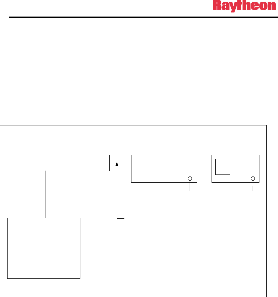
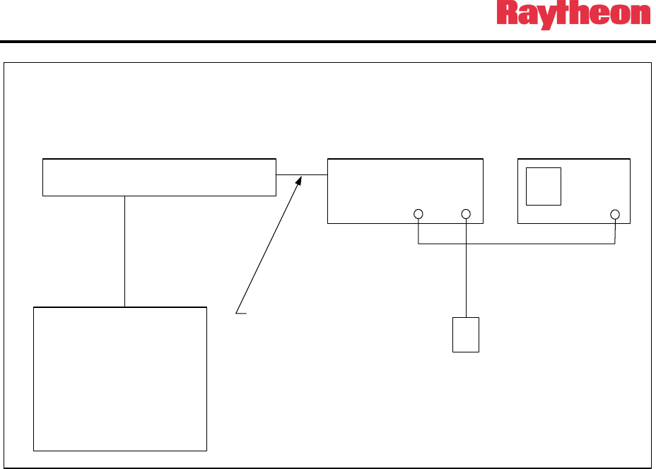
3.9.1 Equipment Set Up
Connect the equipment as shown in Figure 3-8.
Figure 3-8 Tx Calibration Setup
IMPORTANT NOTE: Make sure the test set has an internal 50 ohm attenuator rated for the
transmit power of the radio! It may be necessary to program the radio to a lower power for
the Tx calibration.
Aeroflex 3920
T/R
Radio Under
Calibration
Tx
P25CC
PC
PCCT Calibration
Software
CAT 5 50 ohm coax
P25CC Radio Interface Cable
P25net Channel Controller Operations Manual
3-8
3.9.2 Initial Steps
3.9.2.1 Set the Radio Test Set to analog duplex mode and program for the
frequency of the transmitter.
3.9.2.2 Power up the radio and P25net CC.
3.9.2.3 Launch PCCT and connect to the P25net CC channel.
3.9.3 Radio Tx Calibration
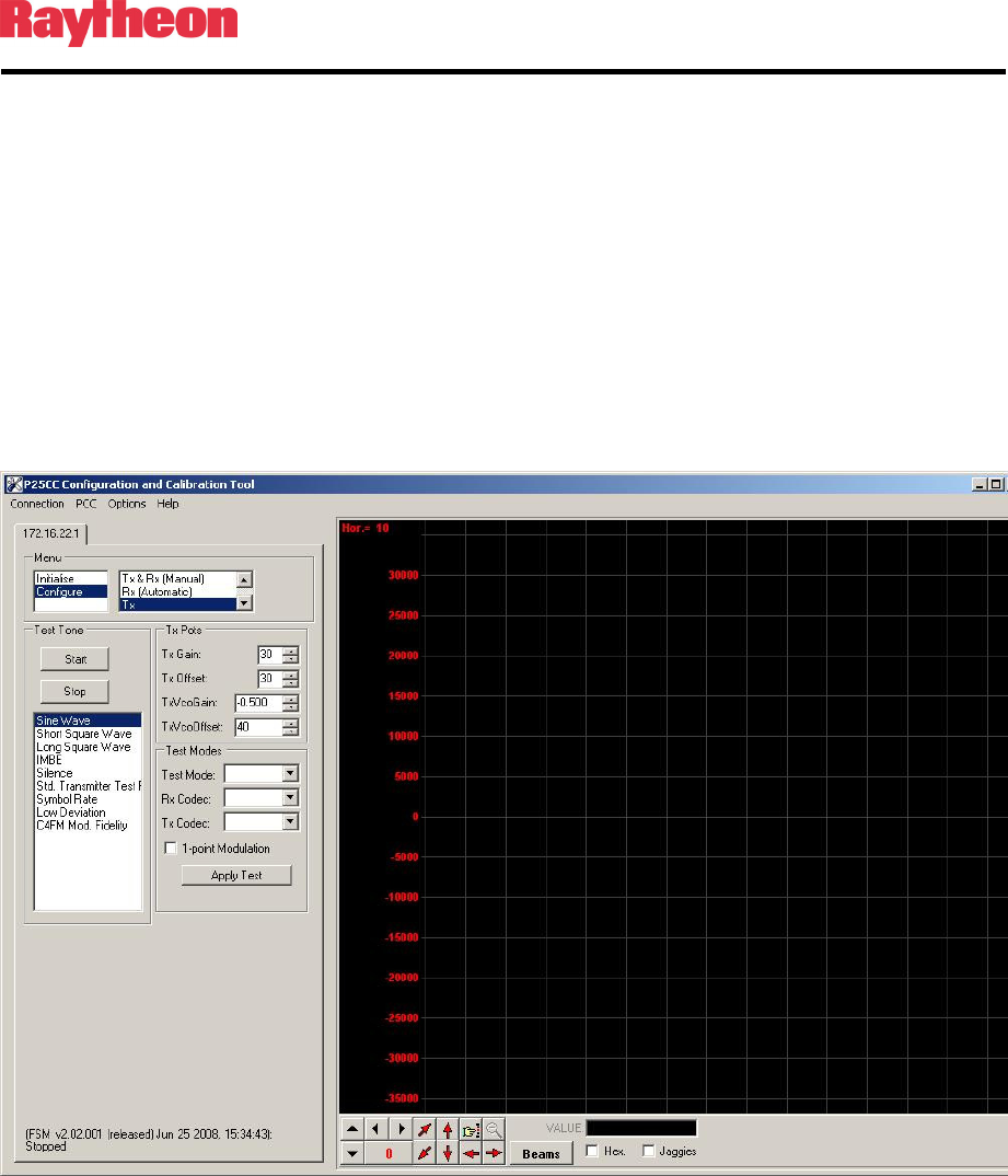
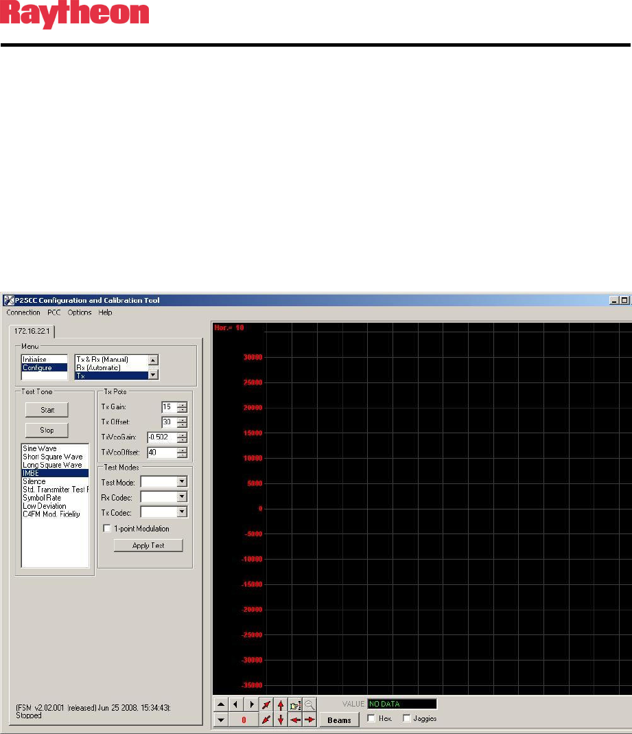
3.9.3.1 In PCCT go to the Configure >Tx window and set default values for the Tx
parameters as shown in Figure 3-9
Figure 3-9 Configure Tx Window
P25net Channel Controller Operations Manual
3-9
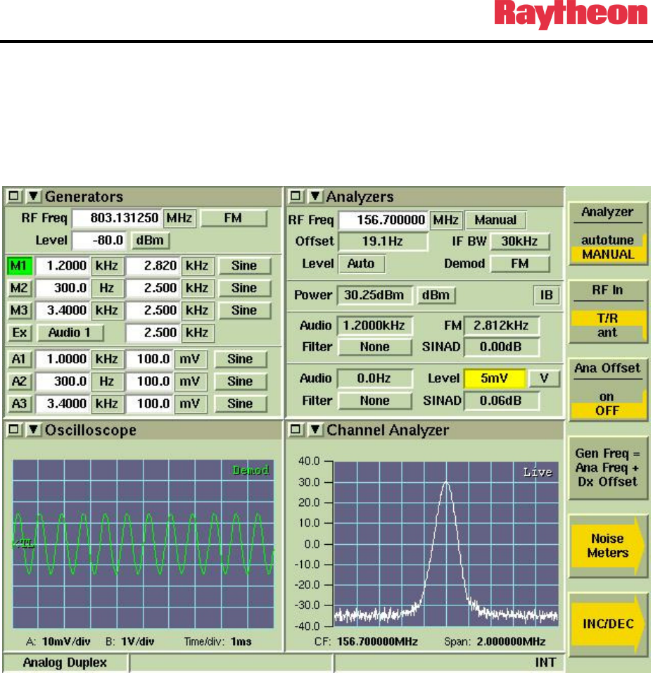
3.9.3.2 Start a Sine Wave test tone and adjust the Tx Gain for approximately +/-
2.8kHz as read on the test set deviation meter (Figure X). Adjust the Tx
Offset if necessary fort a good undistorted sine wave as displayed on the
test set oscilloscope screen (Figure 3-10). Verify the Tx frequency offset
error is within required range. Note: Some radios will produce a frequency
offset if the Tx Offset is incorrectly adjusted.
Figure 3-10 Test Set Oscilloscope: Demodulated Audio
P25net Channel Controller Operations Manual
3-10
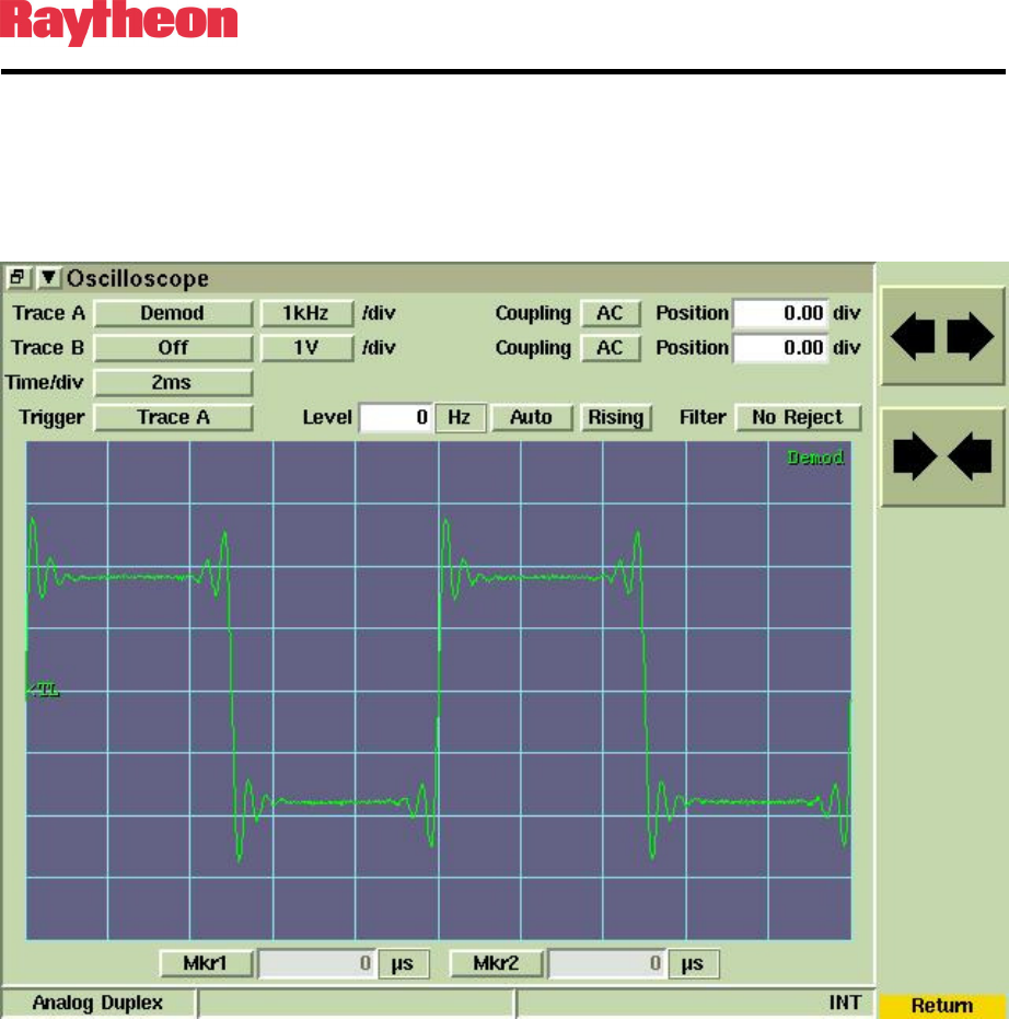
3.9.3.3 Change the test tone selection on PCCT to Short Square Wave (100Hz)
and verify the demodulated audio oscilloscope displays a good
approximation of a square wave with generally flat high and low levels
(Figure 3-11). A poor square wave indicated the radio needs to be aligned
with the factory service software to achieve better DC Balance.
Figure 3-11 Test Set Oscilloscope: Short Square Wave
P25net Channel Controller Operations Manual
3-11
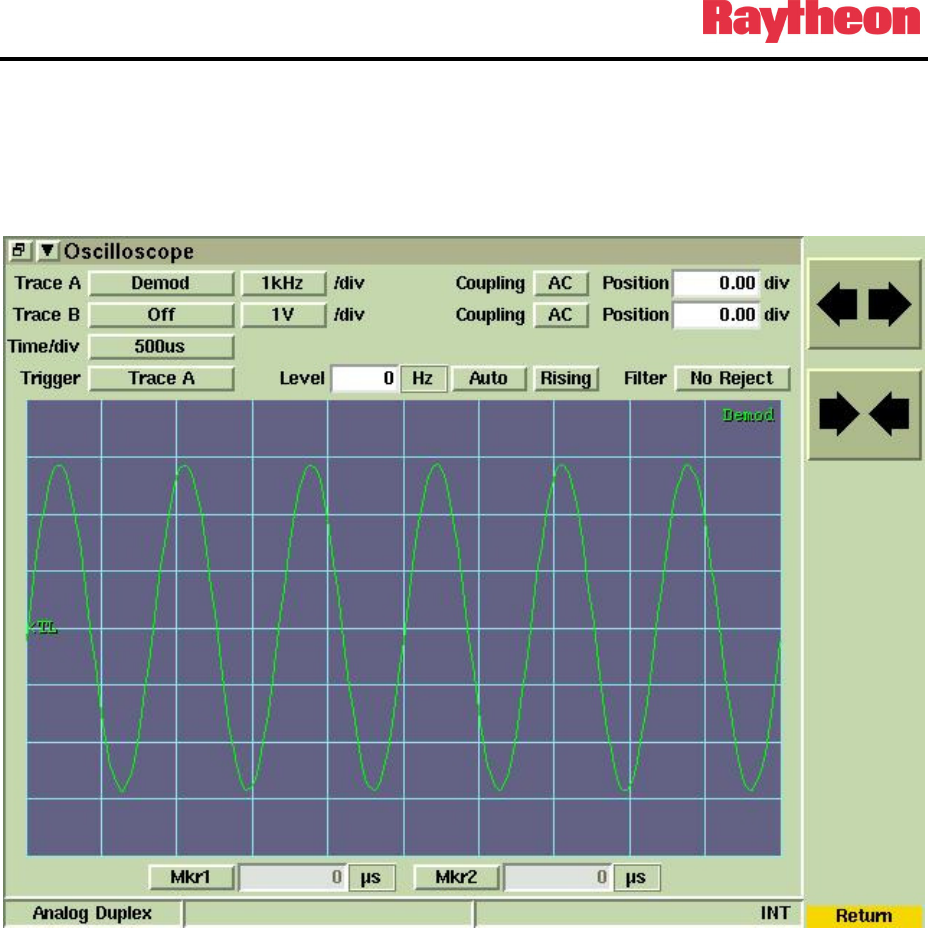
3.9.3.4 Return to the Sine Wave test tone and adjust Tx Vco Gain to get the
deviation as close to +/-2.827kHz as possible and adjust the Tx Offset as
necessary to correct any flattening or clipping of the sine wave. Tx Vco
Gain is a finer adjustment than Tx Gain which provides coarse steps. (See
Figure 3-12).
Figure 3-12 Test Set Oscilloscope: Sine Wave
P25net Channel Controller Operations Manual
3-12
3.9.3.5 Start an IMBE test tone using PCCT.
3.9.3.6 Tune the test set to P25 mode and listen for a 1200Hz sine wave in the
monitor speaker set to demodulated audio. A P25 Handset may also be
used for this step if tuned to the proper frequency in conventional P25
mode.
3.9.3.7 If the test tone is not heard, it may be necessary to invert the Tx audio. This
is done by putting a minus (-) sign in front of the Tx Vco Gain number (see
Figure 3-13). If the tone is heard then Tx calibration is complete. PCCT
writes the Tx calibration settings to the Channel Card when the PCCT
application is closed.
Figure 3-13 Configure Tx Window: Minus Sign for Tx Vco Gain
3.10 Rx Calibration
Receive calibration adjusts the P25net CC audio input level to match the radio line audio output
level and calibrates the P25net CC for the RSSI signal from the receiver.
3.10.1 Equipment Setup
Connect the equipment as shown in Figure 3-14.
P25net Channel Controller Operations Manual
3-13
Aeroflex 3920
T/R
Radio Under
Calibration
Tx
P25CC
PC
PCCT Calibration
Software
CAT 5 50 ohm coax
Rx
50 ohm dummy load
50 ohm coax
P25CC Radio Interface Cable
Figure 3-14 Rx Calibration Set-up
P25net Channel Controller Operations Manual
3-14
3.10.2 Initial Steps
3.10.2.1 Configure the test set for analog duplex mode and set the generator to
produce a 1200Hz sine wave with a peak deviation of 2.827kHz at the
receiver frequency.
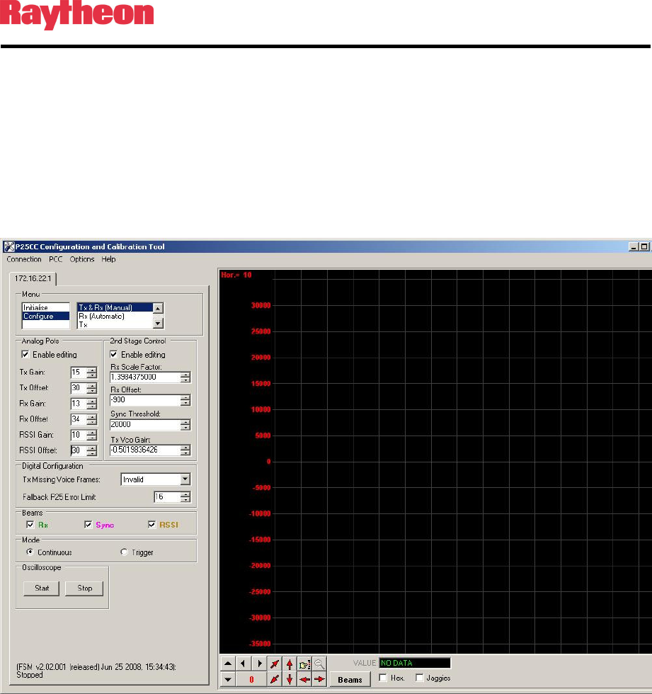
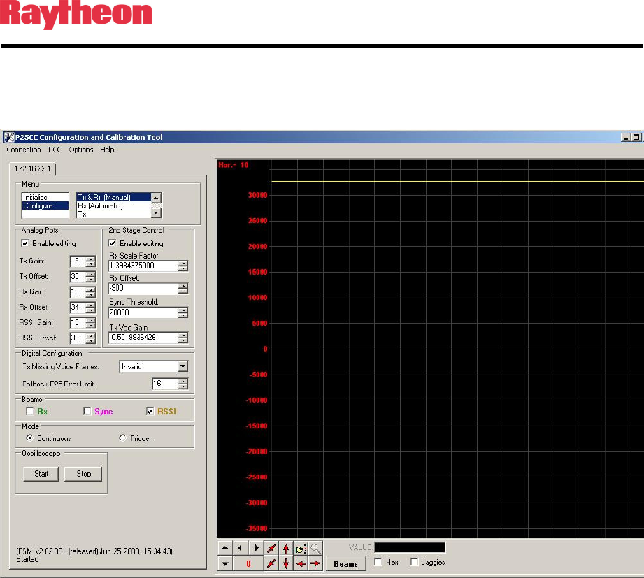
3.10.2.2 In PCCT go to the Configure >Rx and Tx Manual window and set default
values for the Rx parameters as shown in Figure 3-15. Check the “Enable
Editing” boxes for entering parameters.
Figure 3-15 Configure Tx and Rx (Manual) Window
P25net Channel Controller Operations Manual
3-15
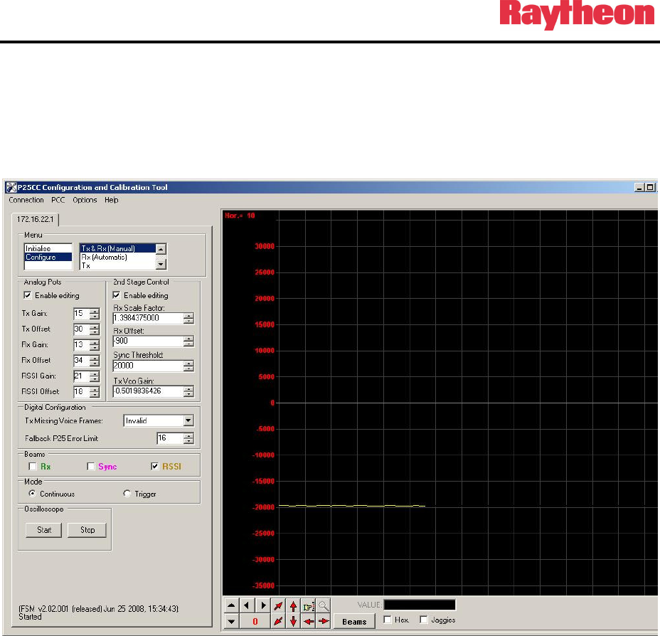
3.10.3 RSSI Calibration
3.10.3.1 Set the test set for -123dBm generator level and turn on the generator.
3.10.3.2 Start the PCCT oscilloscope and adjust the RSSI Offset so the trace on the
oscilloscope is centered around -20000 (See Figure 3-16).
Figure 3-16 RSSI Low Level
3.10.3.3 Turn off the generator and verify the RSII level is unchanged.
P25net Channel Controller Operations Manual
3-16
3.10.3.4 Turn off the generator and change the level to -118dBm. Turn on the
generator and verify RSSI goes to 30000 or above on the oscilloscope
(Figure 3-17).
Figure 3-17 RSSI High Level
3.10.3.5 Turn off the generator; RSSI settings will be saved when exiting PCCT.
3.10.4 Rx Calibration
3.10.4.1 From the Configure>Rx and Tx Manual screen set the following to default
values:
Rx Gain to 15
Rx Offset to 30
P25net Channel Controller Operations Manual
3-17
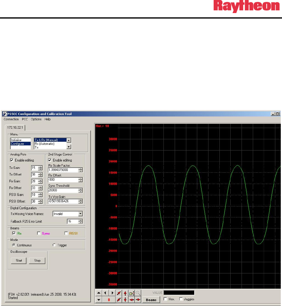
3.10.4.2 Set the generator on the test set to -60dBm.
3.10.4.3 Check the Rx beam box and start the oscilloscope on PCCT.
3.10.4.4 Adjust the Rx Offset so the mean of the observed sine wave is centered as
close as possible about zero. Adjust the Rx Gain so that the signal peaks
are slightly less than +20000 and -20000 (See Figure 3-18).
Figure 3-18 Rx Gain and Offset Adjustment
P25net Channel Controller Operations Manual
3-18
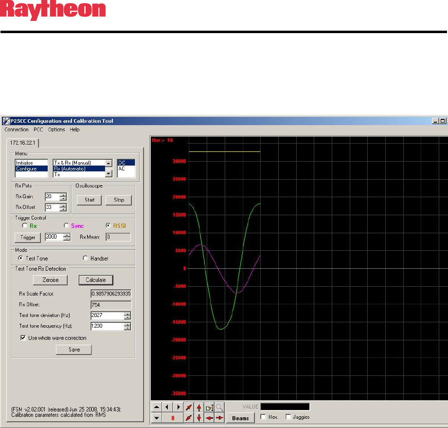
3.10.4.5 Go to the Configure>Rx (Automatic) window and select trigger on RSSI
(2000).
3.10.4.6 Hit Trigger, Calculate, and Save to calculate and store the coefficients for
Rx Scale Factor and Offset (Figure 3-19).
Figure 3-19 Configure Rx Automatic: RSSI Trigger
P25net Channel Controller Operations Manual
3-19
3.10.5 Sync Calibration
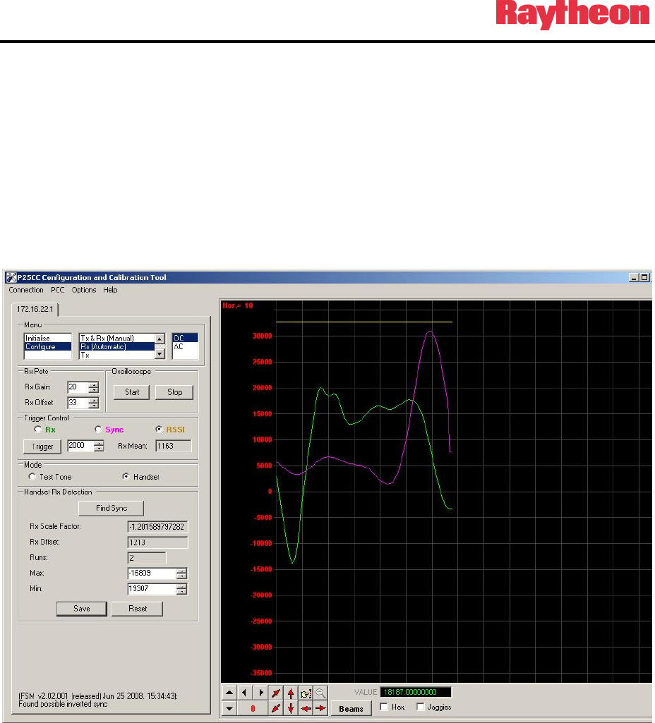
3.10.5.1 Turn off test set generator.
3.10.5.2 Go to the Configure>Rx and Tx (Manual) window and set the trigger
controls for Handset.
3.10.5.3 Press PTT on the Handset for a short transmission.
3.10.5.4 Hit Trigger and Find Sync. You should see the sync pulse as shown in
Figure 3-20.
Figure 3-20 Configure Rx (Automatic): Find Sync
P25net Channel Controller Operations Manual
3-20
3.10.5.5 If the Rx LED on the P25net CC channel lights when the Handset is in
PTT hit the Save button to complete the sync calibration.
3.10.5.6 If the sync is not found, go back to the Configure >Rx (manual) window
and enable editing. Place a negative (-) sign in front of the Rx Scale Factor
and repeat the steps.
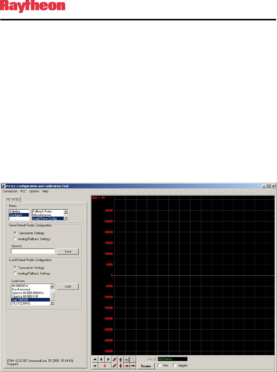
3.11 Load/Save Transceiver Configuration
PCCT has a feature that allows saving the calibration settings for a radio as well as recalling
them. This provides a short-cut around the full calibration procedure in most cases. Sometimes
variation between radios and Channel Cards will require some fine adjustment of the tx/tx
calibration.
3.11.1 Load/Save Config Window
Open
the Configure>Load/Save Config screen and select the transceiver to be loaded (See
Figure 3-21
Load/Save Config Screen
).
Figure 3-21 Load/Save Config Screen
P25net Channel Controller Operations Manual
3-21
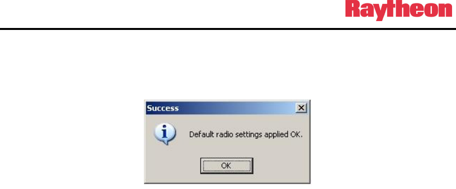
3.11.2 Default Radio Settings Loaded
After loading a notification of the action will be displayed (see Figure 3-22
Default Settings
Applied Screen
).
Figure 3-22 Default Settings Applied Screen
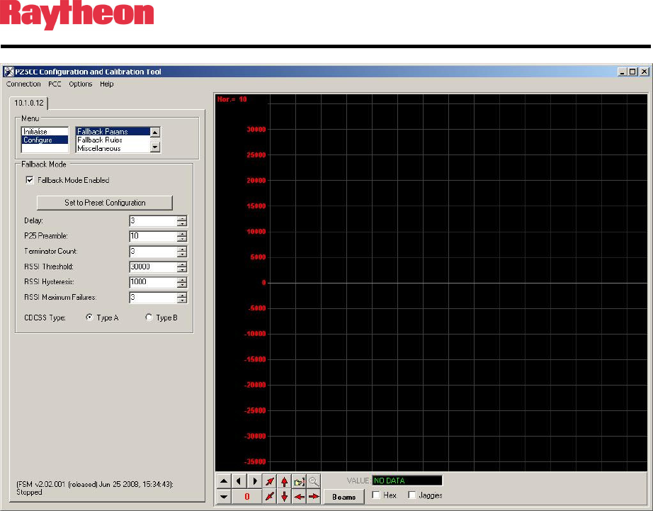
3.12 Fallback Mode
The Fallback Mode can be enabled to provide conventional P25 repeater operation in the event
that the BSC reboots or experiences a problem communicating with the P25net CC. Trunking
will not be possible until BSC operation is restored.
In addition, it is possible to operate the P25net CC as a conventional P25 repeater (sometimes
referred to as a “Dumb Repeater”) without connecting a BSC; this requires enabling the
Fallback Mode.
To enable the Fallback Mode, enter PCCT and select Configure>Fallback Param (see Figure
3-23 Fallback Mode Enable Screen ) and place a check in the box.
P25net Channel Controller Operations Manual
3-22
Figure 3-23 Fallback Mode Enable Screen