Raytheon IDS M3-VHF-136 110W VHF BASE STATION User Manual USERS MANUAL MM102558V1R1A
JPS COMMUNICATIONS, INC. 110W VHF BASE STATION USERS MANUAL MM102558V1R1A
Contents
USERS MANUAL MM102558V1R1A

Overview Manual
MM102558V1
R1A, Jul/06
MASTR® III
Conventional ADC &
P25 Conventional Base Stations

MM102558V1 R1A
MANUAL REVISION HISTORY
REV DATE REASON FOR CHANGE
R1A Jul/06 Initial Release.
M/A-COM Technical Publications would particularly appreciate feedback on any errors found in this document and
suggestions on how the document could be improved. Submit your comments and suggestions to:
Wireless Systems Business Unit or fax your comments to: (434) 455-6851
M/A-COM, Inc.
Technical Publications or e-mail us at: techpubs@tycoelectronics.com
221 Jefferson Ridge Parkway
Lynchburg, VA 24501
ACKNOWLEDGEMENTS
This manual covers M/A-COM products manufactured and sold by M/A-COM, Inc.
This device made under license under one or more of the following US patents: 4,590,473; 4,636,791; 5,148,482; 5,185,796;
5,271,017; 5,377,229.
The voice coding technology embodied in this product is protected by intellectual property rights including patent rights,
copyrights, and trade secrets of Digital Voice Systems, Inc. The user of this technology is explicitly prohibited from
attempting to decompile, reverse engineer, or disassemble the Object Code, or in any way convert the Object Code into
human-readable form.
CREDITS
MASTR and Voice Guard are registered trademarks of M/A-COM, Inc.
GETC, ProVoice and Secur-It are trademarks of M/A-COM, Inc.
Microsoft, Windows, and Windows NT are registered trademarks of Microsoft Corporation
Pentium is a registered trademark of Intel Corporation.
All other brand and product names are registered trademarks, trademarks, or service marks of their respective holders.
NOTICE!
Repairs to this equipment should be made only by an authorized service technician or facility designated by the supplier. Any
repairs, alterations or substitutions of recommended parts made by the user to this equipment not approved by the
manufacturer could void the user's authority to operate the equipment in addition to the manufacturer's warranty.
This product conforms to the European Union WEEE Directive 2002/96/EC. Do not dispose of this product in a
public landfill. Take it to a recycling center at the end of its life.
This manual is published by M/A-COM, Inc., without any warranty. Improvements and changes to this manual necessitated
by typographical errors, inaccuracies of current information, or improvements to programs and/or equipment, may be made
by M/A-COM, Inc., at any time and without notice. Such changes will be incorporated into new editions of this manual. No
part of this manual may be reproduced or transmitted in any form or by any means, electronic or mechanical, including
photocopying and recording, for any purpose, without the express written permission of M/A-COM, Inc.
Copyright© 2006 M/A-COM, Inc. All rights reserved.
2

MM102558V1 R1A
TABLE OF CONTENTS
Page
1 REGULATORY AND SAFETY INFORMATION.......................................................................... 6
1.1 MAXIMUM PERMISSIBLE EXPOSURE LIMITS .................................................................................6
1.2 DETERMINING MPE RADIUS.................................................................................................................. 6
1.3 SAFETY TRAINING INFORMATION .....................................................................................................6
1.4 REGULATORY APPROVALS................................................................................................................... 7
1.5 SAFETY SYMBOL CONVENTIONS ........................................................................................................ 8
2 PREFACE ............................................................................................................................................ 9
2.1 ABOUT THIS MANUAL .............................................................................................................................9
2.2 GLOSSARY OF TERMS ........................................................................................................................... 10
2.3 CUSTOMER SERVICE ............................................................................................................................. 11
2.3.1 Technical Support........................................................................................................................... 11
2.3.2 Customer Resource Center............................................................................................................. 12
3 SPECIFICATIONS ........................................................................................................................... 13
3.1 CABINET..................................................................................................................................................... 13
3.2 SOURCE POWER DRAIN ........................................................................................................................ 13
3.3 STATION..................................................................................................................................................... 14
3.4 INTERFACE ............................................................................................................................................... 14
3.5 TRANSMITTER ......................................................................................................................................... 15
3.6 RECEIVER.................................................................................................................................................. 16
3.7 INDIVIDUAL EQUIPMENT WEIGHTS................................................................................................. 18
4 GENERAL INFORMATION........................................................................................................... 19
4.1 REFERENCE MANUALS ......................................................................................................................... 19
4.2 MASTR III ADC STATION OPTIONS.................................................................................................... 20
5 OPERATION..................................................................................................................................... 25
5.1 CONVENTIONAL STATION CONFIGURATIONS ............................................................................. 25
5.1.1 Conventional Base Station.............................................................................................................. 25
5.1.2 Conventional Repeater.................................................................................................................... 26
5.1.3 Remote-to-Repeater........................................................................................................................ 26
5.1.4 Transmit Only................................................................................................................................. 26
5.2 ENCRYPTED STATION CONFIGURATIONS...................................................................................... 26
5.2.1 End-to-End Encryption................................................................................................................... 26
5.2.2 RF-Only Encryption/Decryption .................................................................................................... 27
5.3 MODES OF OPERATION......................................................................................................................... 27
5.3.1 Analog FM...................................................................................................................................... 27
5.3.2 Data ................................................................................................................................................ 27
5.3.3 Digital Voice................................................................................................................................... 27
5.4 ENCRYPTION FORMATS ....................................................................................................................... 28
5.4.1 Data Encryption Standard (DES).................................................................................................... 28
5.4.2 Voice Guard Encryption (VGE)..................................................................................................... 28
5.4.3 Advanced Encryption Standard ...................................................................................................... 29
5.5 P25 CONVENTIONAL CONFIGURATIONS......................................................................................... 29
5.5.1 P25 Conventional Station Operation ..............................................................................................29
5.5.2 P25 Conventional Repeater Station Operation ............................................................................... 30
5.5.3 P25 Conventional Station with Console......................................................................................... 30
5.6 PROGRAMMABLE FEATURES FOR CONVENTIONAL STATIONS.............................................33
5.6.1 Conventional Stations (Setup) ........................................................................................................ 34
3

MM102558V1 R1A
TABLE OF CONTENTS
Page
5.6.2 Main Station Data ...........................................................................................................................34
5.6.3 Push-to-Talk Options......................................................................................................................36
5.6.4 Other Potentiometer Settings..........................................................................................................36
5.6.5 Carrier Control Timer .....................................................................................................................36
5.6.6 Squelch Tail Elimination ................................................................................................................37
5.6.7 Drop Out Delay Timer....................................................................................................................37
5.6.8 Control Shelf Options .....................................................................................................................37
5.6.9 Station Remote Control...................................................................................................................38
5.6.10 Auxiliary Control Relay..................................................................................................................41
5.6.11 Squelch Operated Relay..................................................................................................................41
5.6.12 Channel Guard Monitor..................................................................................................................41
5.6.13 System Module - Digital Signal Processing....................................................................................42
6 MASTR III ADC STATION DESCRIPTION................................................................................ 43
6.1 MASTR III ADVANCED DIGITAL CAPABLE T/R SHELF................................................................43
6.1.1 Interface Board ...............................................................................................................................44
6.1.2 Backplane........................................................................................................................................44
6.2 STATION EQUIPMENT............................................................................................................................48
6.2.1 Station Power Supply......................................................................................................................48
6.2.2 DC Power Distribution Panel..........................................................................................................48
6.2.3 RF Power Amplifier Assembly.......................................................................................................48
6.2.4 RF Antenna Switch Assembly........................................................................................................49
6.2.5 Cabinet Enclosures and Open Rack Assembly ...............................................................................49
TABLES
Table 1-1: Regulatory and Standards Approval List.............................................................................7
Table 2-1: Glossary of Terms..............................................................................................................10
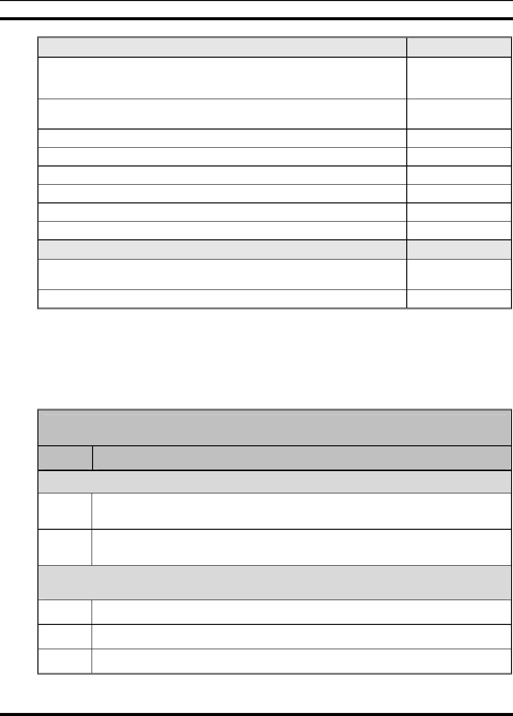
Table 4-1: Reference Manuals.............................................................................................................19
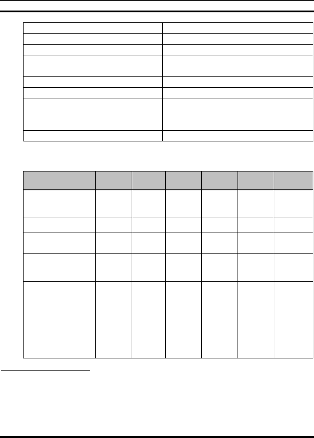
Table 4-2: MASTR III ADC Pre-Configured Conventional Station Packages................................... 20
Table 4-3: MASTR III ADC Conventional Station Options and Accessories ....................................22
Table 4-4: MASTR III ADC Programming, Test and Alignment Tools.............................................24
Table 5-1: Typical* Tone Functionality for Tone Remote Control Signaling ....................................41
FIGURES
Figure 2-1: Examples of MASTR III Conventional Base Stations .......................................................9
Figure 5-1: MASTR III P25 Conventional Station Functional Diagram.............................................31
Figure 5-2: MASTR III P25 Conventional Simplified Interconnect Diagram....................................32
Figure 5-3: Tone Remote Control Signaling....................................................................................... 40
Figure 6-1: Advanced Digital Capable T/R Shelf (Equipped for Conventional FM)..........................44
Figure 6-2: MASTR III ADC T/R Shelf Backplane and Interface Board...........................................45
Figure 6-3: Transmitter Synthesizer Module.......................................................................................45
Figure 6-4: Receiver Synthesizer Module...........................................................................................45
Figure 6-5: Receiver Front End Module..............................................................................................45
Figure 6-6: Receiver IF Module ..........................................................................................................46
Figure 6-7: System Module.................................................................................................................46
Figure 6-8: Data Module .....................................................................................................................47
Figure 6-9: AMPF Module.................................................................................................................. 47
4

MM102558V1 R1A
TABLE OF CONTENTS
Page
Figure 6-10: Power Module.................................................................................................................47
Figure 6-11: DSP Module ...................................................................................................................47
Figure 6-12: 120 VAC Switching Power Supply................................................................................48
Figure 6-13: 240 VAC Switching Power Supply................................................................................48
Figure 6-14: RF Power Amplifier .......................................................................................................49
Figure 6-15: Antenna Switch............................................................................................................... 49
5

MM102558V1 R1A
1 REGULATORY AND SAFETY INFORMATION
1.1 MAXIMUM PERMISSIBLE EXPOSURE LIMITS
DO NOT TRANSMIT with this base station and antenna when persons are within the MAXIMUM
PERMISSIBLE EXPOSURE (MPE) Radius of the antenna. The MPE Radius is the minimum distance
from the antenna axis that ALL persons should maintain in order to avoid RF exposure higher than the
allowable MPE level set by the FCC.
FAILURE TO OBSERVE THESE LIMITS MAY ALLOW ALL PERSONS
WITHIN THE MPE RADIUS TO EXPERIENCE RF RADIATION
ABSORPTION, WHICH EXCEEDS THE FCC MAXIMUM PERMISSIBLE
EXPOSURE (MPE) LIMIT. IT IS THE RESPONSIBILITY OF THE BASE
STATION OPERATOR TO ENSURE THAT THE MAXIMUM PERMISSIBLE
EXPOSURE LIMITS ARE OBSERVED AT ALL TIMES DURING BASE
STATION TRANSMISSION. THE BASE STATION OPERATOR IS TO
ENSURE THAT NO BYSTANDERS ARE WITHIN THE RADIUS LIMITS.
1.2
1.3
DETERMINING MPE RADIUS
THE MAXIMUM PERMISSIBLE EXPOSURE RADIUS is unique for each site and is determined
during site licensing time based on the complete installation environment (i.e. co-location, antenna type,
transmit power level, etc.). Determination of the MPE distance is the responsibility of the installation
license. Calculation of the MPE radius is required as part of the site licensing procedure with the FCC.
SAFETY TRAINING INFORMATION
YOUR M/A-COM MASTR® III BASE STATION GENERATES RF
ELECTROMAGNETIC ENERGY DURING TRANSMIT MODE. THIS BASE
STATION IS DESIGNED FOR AND CLASSIFIED AS “OCCUPATIONAL USE
ONLY” MEANING IT MUST BE USED ONLY IN THE COURSE OF
EMPLOYMENT BY INDIVIDUALS AWARE OF THE HAZARDOUS RF
ENERGY AND THE WAYS TO MINIMIZE EXPOSURE. THIS BASE
STATION IS NOT INTENDED FOR USE BY THE “GENERAL
POPULATION” IN AN UNCONTROLLED ENVIRONMENT. IT IS THE
RESPONSIBILITY OF THE LICENSEE TO ENSURE THAT THE MAXIMUM
PERMISSIBLE EXPOSURE LIMITS ARE OBSERVED AT ALL TIMES
DURING TRANSMISSION. THE BASE STATION OPERATOR IS TO
ENSURE THAT NO BYSTANDERS COME WITHIN THE RADIUS OF THE
LIMITS
When licensed by the FCC, this base station complies with the FCC RF exposure limits when persons are
beyond the MPE radius of the antenna. In addition, your M/A-COM base stations installation complies
with the following Standards and Guidelines with regard to RF energy and electromagnetic energy levels
and evaluation of such levels for exposure to humans:
6
MM102558V1 R1A
FCC OET Bulletin 65 Edition 97-01 Supplement C, Evaluating Compliance with FCC Guidelines
for Human Exposure to Radio Frequency Electromagnetic Fields.
American National Standards Institute (C95.1 – 1992), IEEE Standard for Safety Levels with
Respect to Human Exposure to Radio Frequency Electromagnetic Fields, 3 kHz to 300 GHz.
American National Standards Institute (C95.3 – 1992), IEEE Recommended Practice for the
Measurement of Potentially Hazardous Electromagnetic Fields – RF and Microwave.
CAUTION
TO ENSURE THAT YOUR EXPOSURE TO RF ELECTROMAGNETIC
ENERGY IS WITHIN THE FCC ALLOWABLE LIMITS FOR
OCCUPATIONAL USE, DO NOT OPERATE THE BASE STATION IN A
MANNER THAT WOULD CREATE AN MPE DISTANCE IN EXCESS OF
THAT ALLOWABLE BY THE FCC.
1.4 REGULATORY APPROVALS
Table 1-1: Regulatory and Standards Approval List
TX
Frequency
Range
(MHz)
Power Output
(Adjustable)
(W)
FCC
ID Number Applicable
FCC Rules
(47CFR)
Industry
Canada
Certification
Number
Applicable
Industry
Canada
Rules
CE
MARK
136-174 10-110 OWDTR-0032-E 22, 90 3636B-0017 RSS-119 N/A
403-450 10-100 OWDTR-0038-E 90 3636B-0038 RSS-119 UHF-L
(403-430 MHz)
450-512 10-100 OWDTR-0039-E 22, 90 3636B-0039 RSS-119 UHF-H
(450-470 MHz)
806-870 10-100 OWDTR-0036-E 90 3636B-0036 RSS-119 N/A
7
MM102558V1 R1A
1.5 SAFETY SYMBOL CONVENTIONS
The following conventions are used to alert the user to general safety precautions that must be observed
during all phases of operation, service, and repair of this product. Failure to comply with these
precautions or with specific warnings elsewhere violates safety standards of design, manufacture, and
intended use of the product. M/A-COM, Inc. assumes no liability for the customer's failure to comply
with these standards.
The WARNING symbol calls attention to a procedure, practice, or the like, which,
if not correctly performed or adhered to, could result in personal injury. Do not
proceed beyond a WARNING symbol until the conditions identified are fully
understood or met.
CAUTION
The CAUTION symbol calls attention to an operating procedure, practice, or the like,
which, if not performed correctly or adhered to, could result in a risk of danger, damage
to the equipment, or severely degrade the equipment performance.
The NOTE symbol calls attention to supplemental information, which may improve
system performance or clarify a process or procedure.
The ESD symbol calls attention to procedures, practices, or the like, which could expose
equipment to the effects of Electro-Static Discharge. Proper precautions must be taken to
prevent ESD when handling circuit modules.
The electrical hazard symbol is a WARNING indicating there may be an electrical
shock hazard present.
8
MM102558V1 R1A
2 PREFACE
2.1 ABOUT THIS MANUAL
This manual is written for the communications professional responsible for maintaining MASTR III
Advanced Digital Capable (ADC) Conventional or P25 Conventional base station equipment.
This manual provides specifications and an overview of the MASTR III ADC Conventional and P25
Conventional base station, and introduces the suite of manuals that provide installation and maintenance
instructions for the MASTR III Conventional base stations.
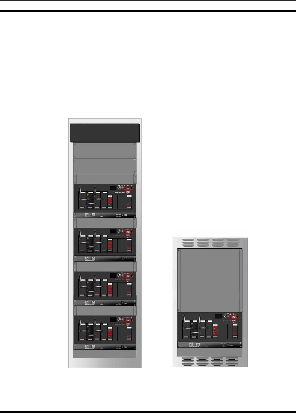
69” Cabinet Installation
37” Cabinet Installation
Figure 2-1: Examples of MASTR III Conventional Base Stations
9

MM102558V1 R1A
2.2 GLOSSARY OF TERMS
The following is a list of terms and acronyms used in this manual:
Table 2-1: Glossary of Terms
ADC Advanced Digital Capable
AES Advanced Encryption Standard
AGC Automatic Gain Circuit
AME Adaptive Multi-band Encoding
AMPF Adaptive Multi-path Pop Filter
CAI Clear Air Interface
CAS Carrier Activity Sensor
CCT Carrier Control Timer
CFR Code of Federal Regulations
CG Channel Guard
CIU Console Interface Unit
COR Carrier Operated Relay
CTCSS Continuous Tone Coded Squelch System
CTI Centralized Telephone Interconnect
CUE Customer Unique Encryption
DCG Digital Channel Guard
DES Data Encryption Standard
DES Digital Encryption Standard
DODT Drop Out Delay Timer
DSP Digital Signaling Processor
DSP Digital Signal Processing
DTMF Dual Tone Multi Frequency
DVIU Digital Voice Interface Unit
E/D Encode/Decode
EIA Electronic Industries Alliance
FCC Federal Communications Commission
FM Frequency Modulation
GETC Generic EDACS Trunking Card
GMSK Gaussian Minimum Shift Keying
ID Identification
IF Intermediate Frequency
IMBE Improved Multi-Band Exciter
LED Light Emitting Diode
10

MM102558V1 R1A
LO Local Oscillator
NRZ Non-Return to Zero
P25 Project 25
PA Power Amplifier
PC Personal Computer
PLL Phased Lock Loop
PTT Push-to-Talk
RF Radio Frequency
RU Rack Unit
RX Receive
STE Squelch Tail Elimination
T/R Transmitter/Receiver
TAC Technical Assistance Center
TIA Telecommunications Industry Association
TX Transmit
UHF Ultra High Frequency, refers to the 370-512 MHz Band
VG Voice Guard®
VGE Voice Guard Encryption
VGS Voice Guard Standard
VHF Very High Frequency, refers to the 136-174 MHz Band
2.3 CUSTOMER SERVICE
2.3.1 Technical Support
M/A-COM’s Technical Assistance Center (TAC) resources are available to help you with overall system
operation, maintenance, upgrades, and product support. TAC is your point of contact when you need
technical questions answered.
Product specialists, with detailed knowledge of product operation, maintenance, and repair, provide
technical support via a toll-free telephone number (in North America). Support is also available through
mail, fax, and e-mail.
For more information about technical assistance services, contact your sales representative, or call the
Technical Assistance Center directly at:
North America: 1-800-528-7711
International: 1-434-385-2400
FAX: 1-434-455-6712
E-mail: tac@tycoelectronics.com
11

MM102558V1 R1A
2.3.2 Customer Resource Center
If any part of the system equipment is damaged on arrival, contact the shipper to conduct an inspection
and prepare a damage report. Save the shipping container and all packing materials until the inspection
and the damage report are completed. In addition, contact the Customer Resource Center to make
arrangements for replacement equipment. Do not return any part of the shipment until you receive
detailed instructions from a M/A-COM representative.
Contact the Customer Resource Center at:
North America:
Phone Number: 1-800-368-3277 (toll free)
Fax Number: 1-800-833-7592 (toll free)
E-mail: customerfocus@tycoelectronics.com
International:
Latin America & Asia Pacific: 1-434-455-9217
Europe, Middle-East & Canada: 1-434-455-9219
Fax Number: 1-434-455-6685
E-mail: InternationalCustomerFocus@tycoelectronics.com
12
MM102558V1 R1A
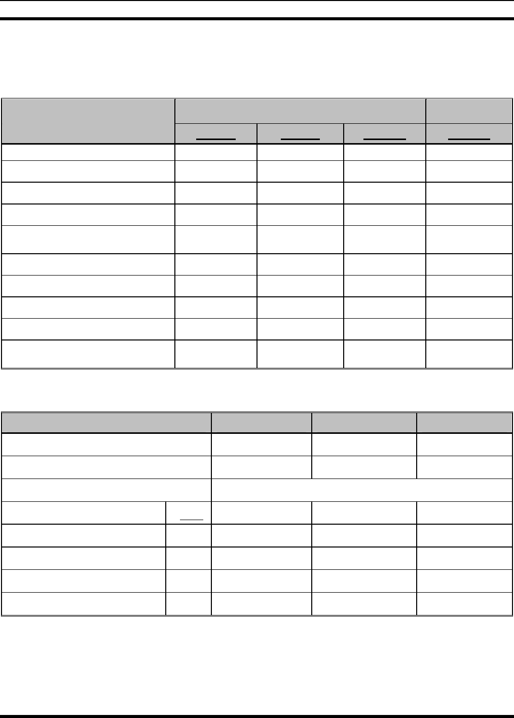
3 SPECIFICATIONS
3.1 CABINET
INDOOR CABINET (Floor Mount) OPEN RACK
37-inch 69-inch 83-inch 86-Inch
Dimensions [in. (cm)]:
Height: 37.0 (94.0) 69.1 (175) 83 (209) 85.5 (217)
Width: 21.5 (55.0) 23.1 in. (59) 23-3/16 (59) 21 (53.3)
Depth: 18.25 (46.0) 21.0 in. (53.3) 21.0 (53.3) 21 (53.3)
Weight
(with max. number of channels)
Continuous Duty: 121 lbs (55 kg) 576 lbs (261 kg) 693 lbs (314 kg)
Packed, Domestic Shipping: 136 lbs (62 kg) 606 lbs (275 kg) 729 lbs (331 kg)
Rack Units (RU) (1 RU = 1.75 in.)
Cabinet capacity 17 RU 33 RU 41 RU 46 RU
Maximum Radio Units:
(using 1-RU power supplies) 2 4 5 5
3.2 SOURCE POWER DRAIN
VHF UHF 800
TX Frequency Range (MHz) 136-174 380-512 851-870
RX Frequency Range (MHz) 136-174 370-512 806-825
AC Input Power 5A @ 120 VAC or 3A @ 230 VAC
DC Input Power (A) VDC
Tx 13.8 2 2 2
Rx only 13.8 2 2 2
Tx (full/half power) 26.4 12/8 12/8 12/8
Rx only 26.4 0.5 0.5 0.5
13

MM102558V1 R1A
3.3 STATION
General: One RF Station Occupies 8-RU
(includes T/R Shelf, RF PA, & 1-RU Power
Supply)
Service Speaker: 1 watt at 8 ohms
Service Microphone: Transistorized Dynamic
Duty Cycle (EIA) Continuous: Transmit and Receive at 100%
Operating Temperature: -22°F to +140°F (-30°C to +60°C)
Humidity (EIA): 90% at 122°F (50°C)
Input Power Source: 120 VAC (±20%), 47-63 Hz
Optional Input Power Source: 230 VAC (±15%), 47-63 Hz
Standby Battery Source: 26.4 VDC, 50 AHR (min.)
Antenna Connections: Type N
Length of AC Power Cable: 10 ft (3048 mm)
Metering: Provided through Handset or TQ0619 Software
Altitude:
Operating: Up to 15,000 ft (4,570 m)
Shippable: Up to 50,000 ft (15,250 m)
3.4 INTERFACE
Line Interface: 2-wire or 4-wire (software selectable)
Line Cancellation: (2-wire) 20 dB amplitude only (software
controllable)
Audio (line to transmitter):
Line Terminating Impedance: 600 ohms (2-wire or 4-wire)
Line Input Level (adjustable): -20 dBm to +7 dBm
Frequency Response: ±3 dB @ 300 to 3000 Hz
Tone Remote Control:
Function Tones (Hz): 1050, 1150, 1250, 1350, 1450, 1550, 1650, 1750,
1850, 1950, & 2050
Secur-it Tone and Transmit Tone: 2175 Hz
Permissible Control Line loss @ 2175 Hz: 27 dB
14
MM102558V1 R1A
Audio (receiver to line):
Audio Amplifier Input Impedance: 10K ohms
Input Level: 1 Vrms (for 5 kHz Deviation)
Output Impedance to Line: 600 ohms (2-wire or 4-wire)
Output Level to Line (1 kHz ref.): +7 dBm (adjustable)
Tone (1 kHz ref.): +7 dBm (Reference 7 dBm)
Frequency Response: +1 and –3 dB @ 300 to 3000 Hz
Hum and Noise, Noise Squelch: -55 dBm (Reference 7 dBm)
Tone Squelch: -30 dBm (Reference 7 dBm)
DC Remote Control Currents: -2.5 mA, ±6.0 mA, ±11.0 mA
Line Loop Resistance (maximum): 11K ohms (includes 3K ohm termination)
3.5 TRANSMITTER
VHF
ANALOG VHF P25
DIGITAL UHF
ANALOG UHF P25
DIGITAL 800 MHz
ANALOG 800 MHz P25
DIGITAL
Frequency Range (MHz) 136 - 174 136 - 174 380 - 512 380 - 512 851 – 870 851 – 870
Rated Power Output (W)110 - 110 10 - 110 10-100 10-100
10 - 100 10 - 100
RF Output Impedance (Ω) 50 50 50 50 50 50
Conducted Spurious and
Harmonic Emission -36 dBm -70 dBc -36 dBm -70 dBc -36 dBm -70 dBc
Frequency Stability (ppm)2 ±1.0 ±1.0 ±1.0 ±0.5
external
freq. std.
±1.0 ±0.15
external freq.
std.
Modulation Deviation (kHz)
Wideband 0 to ±5 N/A 0 to ±5.0 N/A 0 to ±5.0 N/A
Narrowband 0 to ±2.5 2.83 kHz
nominal per
TIA 102
CAAB
0 to ±2.5
±
2.83 nominal
per TIA 102
CAAB
N/A 2.83 kHz
nominal per
TIA 102
(CAAB)
FM Noise (dB) -55 N/A -55 N/A -55 N/A
1 Rated power output is measured at the transmitter power amplifier output connector per FCC Certification information.
Any customer-required optional items such as power measuring devices and/or duplexers will introduce loss between the
transmitter output connector and the station cabinet output connector. This loss will reduce the available power at the station
connector.
2 Frequency stability is relative to the stability of the Reference Oscillator. Unless otherwise specified, the value shown in
this table is relative to the internal Reference Oscillator signal which is provided by the corresponding Receiver Synthesizer
Module.
15

MM102558V1 R1A
VHF VHF P25 UHF UHF P25 800 MHz 800 MHz P25
ANALOG DIGITAL ANALOG DIGITAL ANALOG DIGITAL
Channel Spacing (kHz) 12.5/25/30 12.5 12.5/25 12.5 25
12.5
(NPSPAC)
25
Frequency Step Size (kHz) 1.25 1.25 1.25 1.25 6.25 6.25
Frequency Spread Full Spec
(MHz) 2 1.5 2 1.5 0.5 0.5
Audio Distortion (@ 1 kHz) Less than
3% To Mask
47CFR90.2
10d
Less than
3% To Mask
47CFR90.21
0d
Less than
3% TX Mask
47CFR90.210
d
Number of Channels
(Conventional) Up to 12 Up to 12 Up to 12 Up to 12 Up to 12 Up to 12
Audio Response
(pre-emphasis) Within +1/- 3
dB of 6 dB/
octave, 300
to 3000 Hz
per EIA
Mod
Fidelity
<5%
Within +1/- 3
dB of 6 dB/
octave, 300
to 3000 Hz
per EIA
Mod Fidelity
<5% Within +1/- 3
dB of 6 dB/
octave, 300
to 3000 Hz
per EIA
Mod Fidelity
<5%
3.6 RECEIVER
VHF
ANALOG* VHF P25
DIGITAL UHF
ANALOG* UHF P25
DIGITAL 800 MHz
ANALOG* 800 MHz
P25
DIGITAL
Frequency Range (MHz) 136 - 174 136 - 174 370 - 512 370 - 512 806 - 825 806 - 825
RF Input Impedance (Ω) 50 50 50 50 50 50
Channel Spacing (kHz) 12.5/25/30 12.5 12.5/25 12.5/25 25
12.5
(NPSPAC)
25
12.5
(NPSPAC)
Sensitivity (dBm) EIA -116
(12 dB
SINAD)
(0.35 μV)
-116
(5% BER)
(0.35 μV)
-116
(0.35 μV)
-116
(5% BER)
-108 faded
-118
(0.28 μV)
-116
(5% BER)
-108 faded
Threshold Squelch (dBm) -119
(0.25 μV)
N/A -119
(0.25 μV)
-119
(0.25 μV)
-121
(0.18 μV)
N/A
16

MM102558V1 R1A
VHF
ANALOG* VHF P25
DIGITAL UHF
ANALOG* UHF P25
DIGITAL 800 MHz
ANALOG* 800 MHz
P25
DIGITAL
Selectivity 2- Signal
12.5 kHz ≥75 dB ≥60 dB Dig
ACR
≥75 dB ≥60 dB Dig
ACR
≥20 dB
(NPSPAC)
≥80 dB
25 kHz ≥85 dB N/A ≥85 dB N/A ≥80 dB N/A
30 kHz ≥90 dB N/A N/A N/A N/A N/A
Frequency Stability (ppm) ±1.0 ±1.0 ±1.0 ±0.5 ±1.0 ±0.15
external
freq. std.
Signal Displacement
Bandwidth (kHz)
12.5 kHz ±1.0 ±1.0 ±2 N/A ±1.6
(NPSPAC) ±1.0
25 kHz ±2.0 N/A ±1 ±1 ±2 N/A
Intermodulation (dB)
12.5 kHz ≥75 ≥80 ≥75 ≥80 N/A ≥80
25 kHz ≥80 N/A ≥80 N/A ≥80 N/A
30 kHz ≥80 N/A N/A N/A N/A N/A
Spurious and Image
Rejection (dB) ≥90 ≥90 ≥90 ≥90 ≥90 ≥90
Full Specs. (MHz) 2.0 2.0 2.0 2.0 0.5 0.5
Audio Output @ 1000 Hz,
25/30 kHz Channel (W) 1 @ <3%
distortion N/A 1 @ 3%
distortion N/A 1 @ 3%
distortion N/A
* Audio Response (de- emphasis): Within +2/-8 dB of 6 dB/octave (@ Local Speaker), 300 to 3000 Hz per EIA
Within +1/-3 dB of 6 dB/octave (@ Line Output), 300 to 3000 Hz per EIA.
17

MM102558V1 R1A
3.7 INDIVIDUAL EQUIPMENT WEIGHTS
WEIGHT UNIT OR ASSEMBLY
Lbs kg
69-inch cabinet w/ doors and fan assembly 176 80
Power Supply 19A149978 38 17
Switching Power Supply PS103010 8.91 4.04
T/R Shelf (without plug-in modules) 9.6 4.35
T/R Shelf (with plug-in modules) 22.25 10.21
System Module 1.5 0.68
Power Module 1.8 0.82
TX Synthesizer 1.9 0.86
RX Synthesizer 2.15 0.93
RX Front End Module 2.35 1.07
RX IF Module 1.75 0.79
Blank module panel 0.4 0.18
Power Amplifier, 19D902797 20.8 9.43
Power Amplifier, EA101292 9.8 44.45
SureCall Test Unit (with radio) 20 9.07
18

MM102558V1 R1A
4 GENERAL INFORMATION
4.1 REFERENCE MANUALS
It may be necessary to consult one or more of the following manuals. The manuals listed in Table 4-1
may provide additional guidance if you encounter technical difficulties during the installation or testing
process.
Table 4-1: Reference Manuals
DESCRIPTION MANUAL
NUMBER
MASTR III Base Station
MASTR III ADC Base Station Installation Manual MM102554V1
MASTR III ADC Application and Assembly Diagrams MM102555V1
MASTR III ADC T/R SHELF MM102244V1
System Module (19D902590G6) LBI-39176
Power Module (19D902589G2) LBI-38752
MASTR III RF PACKAGE: VHF (136 - 174 MHZ) MM102557V1
Transmit Synthesizer Module (EA101685V1, V2) MM102174V1
Receive Synthesizer Module (EA101684V1, V2) MM102819V1
Receiver Front End Module (19D902782G1, G2) LBI-38642
Receiver IF Module (EA101401V1) MM101886V1
Power Amplifier (EA101292V10, V11, & V12) MM101383V2
MASTR III RF PACKAGE: UHF (380 - 512 MHZ) MM102557V2
Transmit Synthesizer Module (EA101685V11, V12, V13) MM102174V2
Receive Synthesizer Module (EA101684V11, V12, V13) MM102819V2
Receiver Front End Module (19D902782G6, G8, G9, G10, G11, & G12) LBI-39129
Receiver IF Module (EA101401V1) MM101886V1
Power Amplifier (EA101292V21, V22) MM101292V3
MASTR III RF PACKAGE: 800 MHz MM102557V3
Transmit Synthesizer Module (EA101685V5) MM102147V3
Receive Synthesizer Module (EA101684V5) MM102819V3
Receiver Front End Module (19D902782G5) LBI-39028
Receiver IF Module (EA101794V1) MM102407V1
Power Amplifier, 100 Watt (EA101292V1) MM101383V1
19
MM102558V1 R1A
OPTIONS AND ACCESSORIES
MASTR III Adaptive Multi-path POP Filter (AMPF), Option SXDE9C:
Installation Manual:
Maintenance Manual:
AE/LZT 123 3244/1
AE/LZB 119 3149/1
MASTR III Data Module, Option SXDE5B: 19D904558G1 Rev. 1 and earlier:
19D904558G1 Rev. A and later: LBI-38918
MM-008429-001
Site Grounding and Protection Guidelines AE/LZT 123 4618/1
Tower Requirements and General Specifications LBI-39185
Base Station Switching Power Supply Maintenance Manual (PS103010V120) MM22315
AC Outlet Strip Maintenance Manual LBI-4841
Blower Kit Maintenance Manual LBI-4842
MASTR III Fuse Panel (12/24 Volt) Maintenance Manual LBI-30246
TEST AND PROGRAMMING
RF Module Test Fixture (TQ0650) - Model TS101285V11
- Model 344A4153P1 MM101885V1
LBI 38805
MASTR III Programming Guide (TQS3353) MM102518V1
4.2 MASTR III ADC STATION OPTIONS
The MASTR III ADC Conventional base station is available in the following configurations and may be
combined with the options listed. A brief description of individual modules, hardware and features listed
below can be found in later sections of this manual.
Table 4-2: MASTR III ADC Pre-Configured Conventional Station Packages
PRE-CONFIGURED STATION PACKAGES
OPTION DESCRIPTION
UNENCRYPTED MASTR III STATIONS, PRE-CONFIGURED MODELS IN 37” CABINET
SXHMC1 STATION, CONVENTIONAL MASTR III PACKAGE, 150.8-174 MHZ, 110W Includes power supply, 37-inch
cabinet, antenna switch and mounting hardware.
SXUMC1 STATION, CONVENTIONAL MASTR III PACKAGE, 450-470 MHZ, 100W Includes power supply, 37-inch
cabinet, antenna switch and mounting hardware.
UNENCRYPTED MASTR III STATIONS (CONFIGURED WITH T/R SHELF AND RF PA ONLY)
(Cabinet, Power Supply, Antenna Switch, Mounting Hardware and other options must be ordered separately)
SXGMCX STATION, CONVENTIONAL MASTR III, 136-150.8 MHZ, 110W
SXHMCX STATION, CONVENTIONAL MASTR III, 150.8-174 MHZ, 110W
SX8MCX STATION, CONVENTIONAL MASTR III, 806-870 MHZ, 100W
20

MM102558V1 R1A
SXUMCX STATION, CONVENTIONAL MASTR III, 450-470 MHZ, 100W
SXWMCX STATION, CONVENTIONAL MASTR III, 492-512 MHZ, 90W
SXVMCX STATION, CONVENTIONAL MASTR III, 470-494 MHZ, 90W
SXTMCX STATION, CONVENTIONAL MASTR III, 425-450 MHZ, 90W
SXPMCX STATION, CONVENTIONAL MASTR III, 410-430 MHZ, 90W
SXRMCX STATION, CONVENTIONAL MASTR III, 403-425 MHZ, 90W
AEGIS™/VOICE GUARD OPTIONS (FOR UNENCRYPTED MASTR III STATIONS ONLY) END-TO-
END ENCRYPTION
SXVG3F KIT, GETC, AEGIS/VOICE GUARD, END-TO-END REMOTE/REPEATER With modem (for tone remote or
tone remote/repeater stations with end-to end encryption).
NOTE: No encryption or decryption occurs in the Aegis Station shelf.
SXVG3E KIT, GETC™, AEGIS/VOICE GUARD, END-TO-END (For standalone repeaters.)
NOTE: No encryption or decryption occurs in the Aegis Station shelf.
ENCRYPTED MASTR III STATIONS, (INCLUDES CONFIGURED T/R SHELF AND RF PA ONLY)
(Cabinet, Power Supply, Antenna Switch, Mounting Hardware and other options must be ordered separately)
SXGMCXE STATION, 64-BIT ENCRYPTION, CONVENTIONAL MASTR III, 136-150.8 MHZ, 110W
SXHMCXE STATION, 64-BIT ENCRYPTION, CONVENTIONAL MASTR III, 150.8-174 MHZ, 110W
SXGMCXE STATION, 64-BIT ENCRYPTION, CONVENTIONAL MASTR III, 136-150.8 MHZ, 110W
SX8MCXE STATION, 64-BIT ENCRYPTION, CONVENTIONAL MASTR III, 806-870 MHZ, 100W
SXUMCXE STATION, 64-BIT ENCRYPTION, CONVENTIONAL MASTR III, 450-470 MHZ, 100W
SXWMCXE STATION, 64-BIT ENCRYPTION, CONVENTIONAL MASTR III, 492-512 MHZ, 90W
SXVMCXE STATION, 64-BIT ENCRYPTION, CONVENTIONAL MASTR III, 470-494 MHZ, 90W
SXTMCXE STATION, 64-BIT ENCRYPTION, CONVENTIONAL MASTR III, 425-450 MHZ, 90W
SXPMCXE STATION, 64-BIT ENCRYPTION, CONVENTIONAL MASTR III, 410-430 MHZ, 90W
SXRMCXE STATION, 64-BIT ENCRYPTION, CONVENTIONAL MASTR III, 403-425 MHZ, 90W
MASTR III PAGING STATIIONS (FOR TRANSMIT ONLY APPLICATIONS)
(Cabinet, Power Supply, Mounting Hardware and other options must be ordered separately)
SXUMDX TRANSMITTER, CONVENTIONAL MASTR III, 450-470 MHZ, 100W
SXHMDX TRANSMITTER, CONVENTIONAL MASTR III, 150.8-174 MHZ, 110W
SXGMDX TRANSMITTER, CONVENTIONAL MASTR III, 136-150.8 MHZ, 110W
21

MM102558V1 R1A
Table 4-3: MASTR III ADC Conventional Station Options and Accessories
OPTIONS AND ACCESSORIES
OPTION DESCRIPTION
ENCRYPTION/DECRYPTION MODE FOR REMOTE OR REMOTE/REPEATER
(ENCRYPTED MASTR III STATIONS ONLY)
SXVG3D KIT, DES 1027 ENCRYPTION SHELF (INCLUDES GETC). Same as Option SXVV1N except uses DES
algorithm.
SXVW1J KIT, DES ENCRYPTION SHELF (INCLUDES GETC). Same as Option SXVV1N except uses DES algorithm.
SXVV1N KIT, VGE ENCRYPTION SHELF (INCLUDES GETC). Provides encryption/decryption in a tone remote/repeat
station. Module is remotely controlled using function tones. VGE algorithm version.
REMOTE OR REMOTE/REPEATER (FOR UNENCRYPTED MASTR III STATIONS ONLY)
SXVV1S KIT, AEGIS UNENCRYPTED SHELF (INCLUDES GETC). Provides non-encrypted Aegis digital
communications in a tone remote/repeat station. Module is remotely controlled using function tones.
HARDWARE, OPTIONS AND ACCESSORIES
SXCA1U CABINET, 83 IN.
SXCA1D CABINET, 69 IN.
SXCA1S CABINET, 37 IN.
SXMR1D OPEN RACK, 86 IN.
SXCA1X CABINET, 45 IN., OUTDOOR
SXMN2B OPTION, NO CABINET
SXFN1A FAN, 120 VAC, Must be included when installing more than 1 repeater in a 69- or 83-inch cabinet.
SXFA1L FAN, 230 VAC, Must be included when installing more than 1 repeater in a 69- or 83-inch cabinet.
SXFA1N FAN, 12 VDC, Must be included when installing more than 1 repeater in a 69- or 83-inch cabinet.
SXCN1Z OUTLET STRIP, 120 VAC
SXMN9H COVER, CABINET TOP, 69/83 IN. CABINET (CONVENTIONAL)
SXMN7F KIT, MOUNTING HARDWARE, 37 IN. CABINET
SXMN3Y KIT, MOUNTING HARDWARE, 69/83/86 IN. CABINET/RACK
SXMN9C COVER, SCREEN, T/R SHELF
22

MM102558V1 R1A
OPTIONS AND ACCESSORIES
OPTION DESCRIPTION
SXCH1M CHARGER, UHF ONLY, BATTERY STANDBY, 230 VAC, 50 HZ, Same as SXCH1L except 230 VAC/50 Hz.
SXPS5Y POWER SUPPLY, 230 VAC, 50 HZ, 12/24 VDC, 3/15A For 800 MHZ and VHF applications
SXPS9R POWER SUPPLY, 120 VAC, 60 HZ, 12/24 VDC, 6/15A Output
SXCL5Z CABLE, CHARGER TO BATTERY, For use with SXPS9R
SXCL6A KIT, GEL CELL SHELF WITH COVER AND CABLE, For use with SXPS9R
SPK0501 KIT, GEL CELL SHELF CABLES, Kit, contains cables only
SXPD1M PANEL, FUSE, 12/24 VDC
2401 BATTERY, UHF ONLY, GEL CELL, 12 VDC, 26 AH, For use in battery shelf option. Order 4 units per base
station.
SXSU3A KIT, ANTENNA SWITCH
SXSU3J KIT, ANTENNA SWITCH, RAIL MOUNTED
SXDU1K DUPLEXER, Factory Installed, 162-174; 2-12 MHZ MAXIMUM SEPARATION Band pass/Band reject, 162-174
MHz 2-12 MHz Rx/Tx separation, maximum insertion loss 1.5 dB.
SXDU1J DUPLEXER, Factory Installed, 150-162; 2-12 MHZ MAXIMUM SEPARATION Band pass/Band reject, 150-162
MHz 2-12 MHz Rx/Tx separation, maximum insertion loss 1.5 dB.
SXDU1M DUPLEXER, Factory Installed, 450-470 MHZ, 5-30 MHz Rx-Tx sep.
SXDE5B KIT, TX DATA, Provides Voice/Data mode selection. In the data mode, the module will accept NRZ (non-
return to zero) digital input (single polarity or dual polarity in the range of -25 to +25 volts) at speeds up to 9600
bits/sec. (VHF/UHF only, 25 kHz channel only)
SXMK3J KIT, RADIO LINK APPLICATION, Modifies a standard base station into a radio link repeater. Provides
harness and programming to change a simplex tone remote station into a radio link repeater. Used in
conjunction with option applied to another standard base station to complete the Radio Link application.
SXSU3D KIT, SOR RELAY, Provides relays and hardware for SOR and Auxiliary Control.
SXMC3B MICROPHONE, MOBILE (SERVICE)
SXMK3S KIT, SETUP, MASTR III STATION WITH MIII AUXILIARY RX, Provides cabling and hardware for MASTR III
Auxiliary Receiver. Limited to one RX frequency on base stations.
SXSF1W FEATURE, VOTING TONE (1950 HZ), Includes 4-wire audio.
SXSF3J FEATURE, 4 WIRE AUDIO Enable remote station to operate with 4-wire control.
23

MM102558V1 R1A
OPTIONS AND ACCESSORIES
OPTION DESCRIPTION
SXMK3K INSTRUCTION, BACK-TO-BACK REPEATER/STATION #2, This option is applied to a 2nd standard base
station and is used in conjunction with SXMK3J which is applied to the 1st station.
SXMF5H PROGRAMMING, 12.5 KHZ CHANNEL, Factory configured station for narrowband operation (UHF/VHF
Conventional FM Voice Only).
Table 4-4: MASTR III ADC Programming, Test and Alignment Tools
PROGRAMMING, TEST AND ALIGNMENT
OPTION DESCRIPTION
TQS3353 MASTR IIE/MIII PROGRAMMING SOFTWARE, Provides capability of changing radio's functions and
features. Includes TQ0619 Utility Programming Software.
TQS0653 MASTR IIE/MASTER III MSEDIT SOFTWARE, Provides access to special programming features.
SPK9024 UTILITY HANDSET
TQ3356 MASTR IIE/MIII PROGRAMMING CABLE
TQ0650 MODULE ALIGNMENT AND TEST KIT
EA24877-0001 EXTENDER BOARD, For “EA” Series RF Modules
188D5338G1 EXTENDER BOARD, System, Control and Power Modules
193D1094G1 Multi-Purpose Module
24

MM102558V1 R1A
5 OPERATION
The MASTR III ADC station is a RF synthesized computer programmable, Frequency Modulated (FM)
transceiver capable of wideband (25 kHz) or narrowband (12.5 kHz) operation. The MASTR III ADC
station combines modular design and state-of-the-art technology to deliver superior performance and
reliability. MASTR III ADC station incorporates fully shielded and removable modules, front-mount
controls, and remote diagnostics. The station is capable of 100% transmitter duty cycle with
simultaneous receive capability allowing repeater operation.
The MASTR III ADC station hardware may be installed in 19” rack mount cabinets or 19” open racks.
Equipment cabinets are equipped with front and rear doors for full equipment access, key lock security
and available in 37”, 69” and 83” heights. The 86”open-rack is designed to be floor mounted and allows
full accessibility to all sides of the equipment.
Power Supply options for the MASTR III ADC station include 120 VAC or 240 VAC input at 47 Hz to
63 Hz, battery backup options and DC Power Distribution equipment.
The MASTR III ADC station may be equipped with an antenna switch relay for stand-alone base station
configurations, antenna duplexers for stand-alone repeater configurations, or transmitter combiners and
receiver multi-couplers for multi-station installations.
The MASTR III ADC station may be configured as a Conventional Analog or P25 Conventional station.
5.1 CONVENTIONAL STATION CONFIGURATIONS
The MASTR III ADC station is available in Conventional VHF, UHF, and 800 MHz versions and can be
configured to operate as any of the following:
• Conventional Base Station (2-wire or 4-wire audio1)
• Conventional Repeater (Stand-alone, no wire line)
• Conventional Repeater (with wire line control)
• Remote-to-Repeater
• Transmit Only (Paging or other Data Applications)
5.1.1 Conventional Base Station
When configured as a Conventional Base Station, the MASTR III ADC station may be further configured
to operate with 2-wire or 4-wire controllers, providing access to many remote control features including
up to twelve (12) selectable RF channels. Each channel can be individually programmed for either
simplex operation (common TX and RX frequency) or half-duplex operation (different TX and RX
frequency). Each channel may be programmed for any combination of standard sub-audible tone Channel
Guard or Digital Channel Guard.
In standard DC control applications, up to 2 RF channels, RX Channel Guard Disable (monitor) and scan
features may be controlled using loop currents of +6 mA, +11 mA, -6 mA, -11 mA and -2.5 mA. E&M
control is a feature of DC control.
In standard Tone Remote control applications, up to four (4) channels may be accessed via Tone Remote
Control. Other features such as RX Channel Guard Disable (monitor), Scan and Repeater Enable may
also be tone controlled.
Additionally, Dual Tone Multi Frequency (DTMF) signaling sent via the wire line connection can be used
in conjunction with DC or Tone Remote control to allow control of up to twelve (12) selectable channels.
25

MM102558V1 R1A
DTMF tones are sent to the station via the wire line interface where the System Module decodes the tones
as channel assignment information. The DC or Tone Remote signaling then controls the TX/RX
operations of the station on the channel selected by the DTMF signaling.
5.1.2 Conventional Repeater
When configured as a Conventional Repeater, the MASTR III ADC station provides full duplex (different
TX and RX frequencies operating simultaneously) operation as a single channel repeater station. The
repeater may be programmed for any standard Channel Guard, Digital Channel Guard or Type-90 tone.
MASTR III ADC stations configured for repeater operation may also be configured for DC or Tone
Remote control. Console TX and RX, Channel Guard disable and repeater enable are common features
available using 2-wire or 4-wire remote control.
5.1.3 Remote-to-Repeater
When configured as a Remote-to-Repeater station, the MASTR III ADC station provides full duplex
repeater operation just like Conventional Repeaters, with extended capability to share TX, RX and control
operations via 4-wire interfacing with another MASTR III ADC station operating as a Remote Base. The
Remote Base station can be co-located or remotely located at another site.
5.1.4 Transmit Only
MASTR III ADC stations operating as Transmit Only stations provide the necessary equipment to operate
as a One-Way Paging Station or other similar Data transmitters. Only transmitter related modules and
components are provided with the station T/R shelf.
A Data Module is provided for 9600 bps NRZ TX data capability. The Data Module provides the
required 12.8 MHz reference oscillator signal to the TX Synthesizer, thus meaning no RX Synthesizer is
required (the usual source for the 12.8 MHz reference oscillator signal).
5.2 ENCRYPTED STATION CONFIGURATIONS
MASTR III ADC stations equipped with external encryption equipment may be configured one of two
ways:
• End-to-End Encryption
• RF Only Encryption/Decryption
5.2.1 End-to-End Encryption
With end-to-end encryption, the voice encryption occurs at the dispatch center or originating radio and
remains encrypted all the way to the properly equipped mobile or portable radio. External encryption
equipment is located at or nearby the dispatch center and connected to the MASTR III ADC station via
four-wire interconnection. This method of operation provides the highest level of system security.
However, four-wire interconnection with one or more consoles is always in the clear mode. This assumes
that the dispatch center is secure and that the console interconnection will be by short, local cable runs
that are adequately secure.
With end-to-end encryption, Cryptographic key information is not required at the MASTR III ADC
station is located. All key loading occurs at the dispatch center or originating radio where the external
encryption equipment is located.
26

MM102558V1 R1A
5.2.2 RF-Only Encryption/Decryption
In RF-Only Encryption/Decryption (E/D) stations, external encryption equipment is connected directly to
the MASTR III ADC station. The voice signal is always delivered clear (unencrypted) from the dispatch
center to the base station where it can then be encrypted and sent over the radio path to properly equipped
mobiles and portables. One or more station consoles operate in a standard clear mode, tone control
configuration.
In an RF only E/D station, the working cryptographic key must reside in the external encryption
equipment co-located at the MASTR III ADC station site. The external encryption equipment is remotely
controlled to select for CLEAR or GUARDED modes of operation at the start of each transmit PTT,
receive mode selection is automatic. Four-wire control is still a requirement but only a voice grade (not
data grade) circuit is required.
5.3 MODES OF OPERATION
Options are available for conventional MASTR III ADC stations to provide the following modes of
communication:
• Analog FM (Clear Voice)
• Data (Paging and other externally generated NRZ Data formats)
• Digital Voice (unencrypted AEGIS)
• Digital Voice Encryption (Encrypted Voice Guard or encrypted AEGIS)
5.3.1 Analog FM
When operating in conventional analog mode, the MASTR III ADC station communicates via traditional
FM modulation schemes. Narrowband (12.5 kHz) bandwidth is available on the VHF and UHF stations
while Wideband (25 kHz) bandwidth is available on the VHF, UHF and 800 MHz bands.
Both the TX and RX audio circuitry is designed to provide extremely clear audible speech characteristics
from 300 Hz to 3000 Hz, with sub-audible tone capability for Channel Guard requirements.
5.3.2 Data
The MASTR III ADC station may be equipped with a Data Module capable of delivering up to 9600 bps
Non-Return-to-Zero (NRZ) serial data transmissions. This mode of operation provides the necessary
digital interfacing required for paging and other externally generated data formats.
5.3.3 Digital Voice
The MASTR III ADC station may be equipped with an external Digital Voice Interface Unit (DVIU)
capable of encoding and decoding digital signaling. Stations equipped with the external DVIU can
provide one of several digital voice formats, each having certain types of encrypted or unencrypted
services available. The formats and types are as follows:
• Voice Guard (DES and VGE)
• AEGIS (Unencrypted AEGIS, Encrypted with DES, VGE or VGS)
• P25 Conventional (Unencrypted P25, Encrypted with DES and AES)
27

MM102558V1 R1A
5.3.3.1 Voice Guard
Voice Guard is the first generation digital voice format available only as an encrypted signal. Voice
Guard signals use Gaussian Minimum Shift Keying (GMSK), running at 9600 bps, two level FM
modulation, Non-Return-to-Zero (NRZ), serial data. This means that the data is a serial train of two-state
data bits (i.e., ones and zeros) occurring at the rate of 9600 bits per second. The NRZ characteristic
means that the duration of each data bit is a full clock period (approximately 104 microseconds) instead
of returning to zero before the next bit time starts.
Voice Guard is available in two types of encryption provided by either of two different algorithms. These
algorithms are:
• Data Encryption Standard (DES)
• Voice Guard Encryption (VGE)
These algorithms are the mathematical manipulations used to scramble the digitized voice bit pattern.
Both algorithms offer the user a higher level of voice security by virtue of the extremely large number of
available cryptographic keys. The availability of encryption devices are subject to national and
international export laws.
5.3.3.2 AEGIS
AEGIS is a second generation digital voice format, available in both encrypted and unencrypted formats.
AEGIS uses Adaptive Multi-band Encoding (AME). AME offers enhanced voice quality characteristics
over Voice Guard technology. AEGIS operates at 9600 bps, two level FM, with encryption provided by
DES or VGE algorithms.
5.4 ENCRYPTION FORMATS
5.4.1 Data Encryption Standard (DES)
DES is a public domain encryption system. DES employs a 64 bit cryptographic key, 56 bits of which are
used for encryption and the remaining eight bits are parity bits. This results in 7.2 times 10 to the 16th
power unique cryptographic keys being available. The security of a DES equipped system is a result of
the extremely large number of available keys.
5.4.2 Voice Guard Encryption (VGE)
The VGE algorithm is a very secure, proprietary, encryption algorithm which was developed to meet the
security needs of international and domestic customers. The encryption algorithm utilizes highly complex
non-linear data spreading and iterative key scheduling to insure the security of encrypted voice data.
The VGE algorithm utilizes a 64-bit cryptographic key, and thus offers the security of 1.8 times 10 to the
19th power permutations of keys. It also utilizes a key scheduling algorithm, bit permutations, and non-
linear product transformations to provide a very high level of bit spreading.
Unlike DES, the VGE algorithm offers an additional level of security, in the form of Customer Unique
Encryption (CUE). The programming of a second 64-bit CUE code (16hex characters) allows a user
increased security. Even if two parties use the same cryptographic key, their equipment will not
communicate unless they use the same CUE. This, effectively, increases the number of key and CUE
permutations to 3.4 times 10 to the 38th power, equivalent to 128-bit encryption.
VGS is a customer unique, customer specific encryption algorithm that works very similar to VGE.
28

MM102558V1 R1A
5.4.3 Advanced Encryption Standard
Advanced Encryption Standard (AES) is a block cipher format approved for use as an encryption standard
by the U.S. government. AES is fast in both software and hardware, is relatively easy to implement, and
requires little memory. AES is currently used in conjunction with the P25 technology.
Unlike DES, AES operates as a substitution-permutation network. AES utilizes fixed blocks of data
formed into tables. AES has a fixed block size of 128 bits and a key size of 128, 192 or 256 bits. AES
uses a process of shifting data in a table. The bit shifting techniques are known as AddRoundKey,
SubBytes, ShiftRows and MixColumns. This combination of block data, bit shifting and unique key
driven encryption methodologies provide much further advanced encryption capabilities than DES or
VGE.
5.5 P25 CONVENTIONAL CONFIGURATIONS
VHF and UHF MASTR III ADC stations may be equipped with a DSP Module to allow operation as a
Project 25 (P25) Conventional station. P25 compliant stations use four-level FM modulation (C4FM),
and are backward compatible with traditional analog FM radios. P25 Conventional technology supports
the following modes of communication:
• P25 Conventional Base Station (4-Level FM)
• P25 Conventional Repeater
• P25 Conventional Repeater with Console Control
P25 is an Industry Standard developed to bring Interoperability between different manufacturers, and
users of their respective digital communications equipment. P25 technology uses a standardized digital
format known as Common Air Interface (CAI). CAI incorporates various system information and a
digital voice format into one digital transmission.
While the DSP card located in the MASTR III ADC station provides the P25 formatting, external
equipment is required to encrypt the voice product delivered to the station. External encryption
equipment for P25 Conventional systems is available for three types of encryption:
• DES
• VGE
• AES
The encryption formats are discussed in Section 5.4.
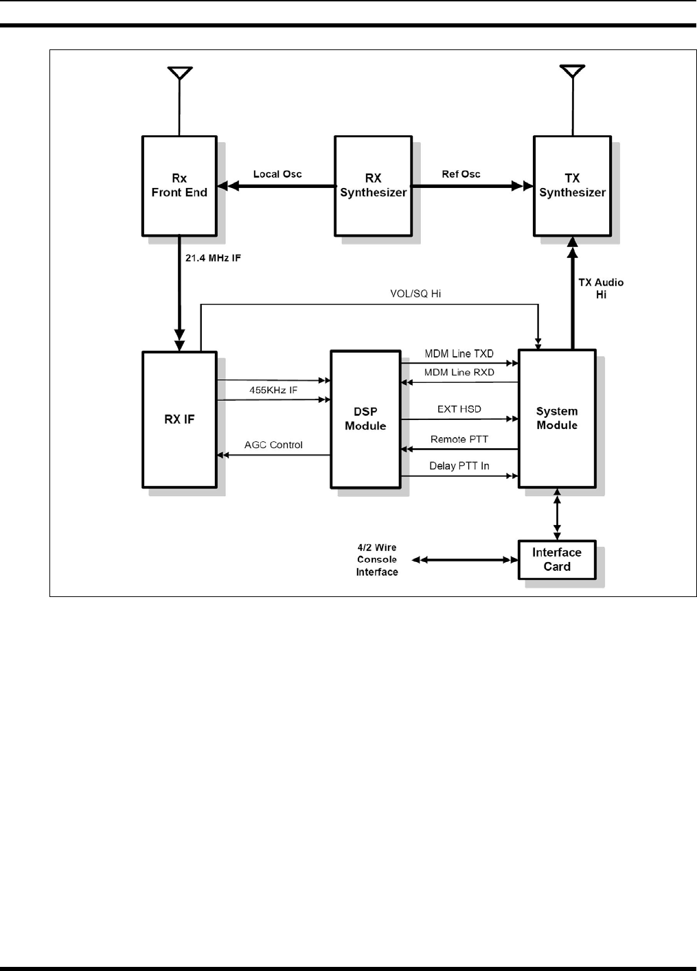
5.5.1 P25 Conventional Station Operation
MASTR III ADC stations operating in P25 Conventional mode utilize additional circuitry in the RX IF
Module to provide the properly filtered and amplified signal required by the DSP Module to decode the
signal. The DSP Module also provides the encoded C4FM signaling for the transmitter.
In the 21.4 MHz RX IF module (VHF and UHF stations), the 455 kHz four-level FM signal passes
through additional IF filtering, a differential amplifier, and a buffer to the 455kHzIF lines on the
backplane. Unlike 2-level signals, the signals present on the 455kHzIF lines are not demodulated. These
lines connect to the DSP Module input where the DSP captures the data signal and processes it as
necessary.
During TX operations, the DSP Module encodes the inbound audio or digital signal into the P25
compliant C4FM modulation scheme and routed via the backplane to the TX Synthesizer Module.
29

MM102558V1 R1A
5.5.2 P25 Conventional Repeater Station Operation
In the P25 Repeater mode, the DSP Module uses the Delay PTT In line and the Remote PTT to
communicate with the System Module. After the DSP Module demodulates a four-level FM signal, it
asserts a Delay PTT In signal to the System Module, indicating a P25 call is being received. While the
Delay PTT In line is applied, the System Module keys the External PTT and disables the Channel Guard
circuitry, preventing further processing of the 455 kHz signal on the VOL-SQ HI line.
The four-level FM signal is passed onto the System Module on the EXT HSD line. The System Module
processes the signal and sends it to the TX Synthesizer Module on the TX Audio Hi line. The External
PTT also keys the transmitter and the signal is re-transmitted. The DSP module continues to assert the
Delay PTT In line until the P25 Terminating Data unit is transmitted.
While the External PTT is keyed, the DSP passes the demodulated analog audio to the System Module on
the MDM Line TXD. The System Module routes the audio to the landline interface for monitoring by the
Console.
5.5.3 P25 Conventional Station with Console
5.5.3.1 Console Transmit
The MASTR III P25 Conventional Base Station also supports analog remote control through the base
station’s 2- or 4- wire landline interface. When communication is initiated by a remote console, the
analog audio is routed through the Interface Card to the System Module. The System Module routes the
audio on MDM Line RXD to the DSP Module. The System Module also sends a Remote PTT signal to
the DSP Module, initiating the four-level FM modulation process.
The DSP Module asserts a Delay PTT In signal to the System Module, indicating a P25 is being sent.
The System Module executes an External PTT, this keys the transmitter and the signal is transmitted. The
modulated four-level FM signal is passed on to the System Module on the EXT HSD line. The System
Module processes the signal and sends it to the TX Synthesizer Module on the TX Audio Hi line. The
DSP module continues to assert the Delay PTT In line until the call is complete and the P25 Terminating
Data unit is transmitted.
5.5.3.2 Console Preempt
The Console Preempt feature allows a dispatcher’s call to preempt a radio call already in progress. This
means the dispatcher’s call is heard by all radios and the transmitting radio is still heard by the dispatcher.
The Console Preempt feature assumes a P25 call is in process (see section 4.2). When the console
initiates a call, the analog audio is routed through the Interface Card to the System Module. The System
Module routes the audio on MDM Line RXD to the DSP Module and sends a Remote PTT signal to the
DSP Module.
The DSP Module initiates the four-level FM modulation process of the console audio. It then switches
from sending the P25 call to sending the four-level FM modulated console audio to the System Module
on the EXT HSD line. The System Module processes the signal and sends it to the TX Synthesizer
Module on the TX Audio Hi line. The System Module continues executing an External PTT, keying the
transmitter and transmitting the console signal.
At the end of the console call, the DSP Module sends the P25 Terminating Data unit. If the P25 Repeat
call still exists, the DSP Module continues to assert the Delay PTT In line until the call is complete and
the P25 Terminating Data message is transmitted.
30
MM102558V1 R1A
Figure 5-1: MASTR III P25 Conventional Station Functional Diagram
31
MM102558V1 R1A
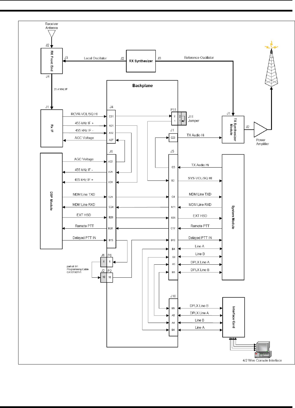
Figure 5-2: MASTR III P25 Conventional Simplified Interconnect Diagram
32

MM102558V1 R1A
5.6 PROGRAMMABLE FEATURES FOR CONVENTIONAL STATIONS
Most MASTR III ADC station features may be accessed using a PC compatible computer and the latest
version TQS3353 Programming Software. Station configurations discussed in Section 5 require features
to be properly set via programming software.
Most MASTR III ADC feature programming is stored in the Station’s System Module. This section of
the manual is written to describe the programmable features of the MASTR III ADC station and how they
apply to Conventional and P25 Conventional base and repeater station operation.
When programming a MASTR III ADC station, it is advisable to read and save
(archive) the personality from the station before attempting to program features.
Always save (archive) any programming changes to a different filename to preserve
the original personality in case the changes you have made are unsuccessful.
Programmable features discussed in this section include the following:
• Conventional Stations (Setup)
o No Remote
o DC Remote
o Tone Remote
o Type 90
o DTMF
• Main Station Data (New)
o Transmit and Receive Frequency
o Channel Guard
o TX Pot
o CG Pot
o RF Simplex and Rpt
o PA Power
• Push-to-Talk Options (PTTs)
o Repeat PTT
o Remote PTT
o Local PTT
o External PTT
o Morse Code ID PTT
• Potentiometer Settings (Pots)
• More Features (Additional)
o Carrier Control Timer
o Squelch Tail Elimination
o Drop Out Delay Timer
• Control Shelf (Options)
o Morse Code ID
o Battery Alarm
o Logic Standby
o Intercom
o Bandwidth
o Receiver Channel Scan
• Station Remote Control
o Two-Wire/Four Wire Operation
o DC Remote Control
o Tone Remote Control
o Auxiliary Control Relays
o Squelch Operated Relay
o Channel Guard Monitor
o System Module - DSP
33

MM102558V1 R1A
5.6.1 Conventional Stations (Setup)
The initial Setup screen in the TQS3353 software allows the station to be defined as one of several
Conventional station types include: No Remote, DC Remote, Tone Remote, Type 90 and DTMF.
Other station types appear in the Setup screen however only the above are applicable to Conventional
stations. The other station types are: Simulcast, Trunked and Multi-Receiver.
5.6.1.1 No Remote
This type of station configuration is typically selected when the station will be operating as a stand-alone
repeater. As the name implies, no remote control features will be activated during this mode.
5.6.1.2 DC Remote
Base, Repeater, and Transmit-only stations may be controlled remotely via 2-wire or 4-wire telephone
line connections using DC Remote control signaling. DC Remote control uses a DC loop current placed
on the phone line to remotely control certain preprogrammed station features such as TX PTT, channel
selection and CG Enable/Disable. Further information on 2-wire and 4-wire operation may be found in
Section 5.6.9.1, and further information about DC Remote control may be found in Section 5.6.9.2
5.6.1.3 Tone Remote
Similar to DC Remote control, Tone Remote control uses audible control tones sent via the phone line to
remotely access certain preprogrammed station features such as TX PTT, channel selection and CG
Enable/Disable. Further information may be found in Section 0.
5.6.1.4 Type 90
With Type 90 (T90) signaling, a station is setup to accept a burst of single-tone transmitted by a mobile or
portable at the beginning of a transmission which activates certain base or repeater station functions such
as CG Disable or Repeater Enable.
For example: when T90 is used to control the Repeater Enable function and the System Module detects
the proper T90 signal, the repeater is keyed and operates in carrier squelch, CG or DCG tone mode until
one of three things occur: the repeater’s receiver is squelched, the repeater’s Drop Out Delay Timer is
reset, or the repeater Time Out Timer un-keys the station and the repeater is disabled until the next valid
T90 tone is received.
There are ten (10) different T90 tones available: 1050 Hz, 1200 Hz, 1350 Hz, 1500 Hz, 1650 Hz, 1800
Hz, 1950 Hz, 2100 Hz, 2250 Hz, and 2400 Hz.
5.6.1.5 DTMF
When DTMF is selected, the station is setup to function as a repeater and uses over-the-air DTMF
signaling to enable or disable the repeater and to make channel selections when multiple receive or
transmit frequencies are assigned during special applications.
5.6.2 Main Station Data
Main station data may be programmed using the New, Change or Read tabs in the TQS3353
programming software. The New tab allows the programmer start with a clear database thereby requiring
all parameters and features to be properly programmed from scratch. The Change tab allows the
programmer to modify an existing data file previously stored to hard drive. The Read tab allows the
programmer to read and save the station personality while directly connected to the station’s Data port.
34

MM102558V1 R1A
The main programmable station data parameters include Transmit and Receive frequency, Channel
Guard, TX Pot settings, CG Pot settings, RF Simplex/Rpt and PA Power settings. The following sections
include a brief description of each parameter.
5.6.2.1 Transmit and Receive Frequency
The System Module is programmed with most of the station’s features including transmit and receive
frequency assignment. Once the correct control station type has been defined, up to twelve (12) channels
may be programmed into one station (16 channels in models with previous vintage System Modules).
5.6.2.2 Channel Guard
A Channel Guard (CG) is a sub-audible (below 300 Hz) tone, used to control one or more functions of a
base or repeater station. CG tones may be used to open (or un-mute) the station’s receiver audio circuit,
provide PTT signaling to stations in repeater mode, or provide control of other station functions. There
are two types of Channel Guard (CG) available:
• Tone Channel Guard (CG)
• Digital Channel Guard (DCG)
The System Module, located in the MASTR III ADC T/R Shelf, can encode CG or DCG tones (generate
tones to be used by the transmitter) or decode received CG or DCG tones. The System Module may be
programmed with different CG or DCG tones on each channel. Each individual channel may also have a
different transmit and receive CG or DCG tone; including a mix, such as DCG for transmit and a CG for
receive.
For DC or Tone Remote controlled stations, the CG Disable (monitor) function, controlled by DC or
Tone Remote control signaling, may override the receiver CG or DCG decoding by un-muting the
receiver and allowing all on-frequency activity to be monitored. When CG or DCG tones are used to key
repeater stations, the transmitter is activated only when the proper CG or DCG tone is decoded, regardless
of the CG Disable condition.
On the System Module, setting the CG MONITOR switch in the UP position (LED indicator lit), causes
the receiver to un-mute and operate in the carrier squelch mode. This has no affect on repeater stations
using DC or DCG tones to signal a PTT request to the transmitter. The transmitter is activated only if the
proper CG or DCG tone is present on the received signal.
5.6.2.2.1 Tone Channel Guard
The industry standard Continuous Tone Coded Squelch System (CTCSS) or CG tones range from 67 Hz
to 210.7 Hz. Extended CG tones above 210.7 Hz are available, but can cause some degradation in
specifications.
The System Module monitors the station’s receive demodulated audio output for a CG tone and signals
the station when the proper CG tone is received. Once the proper receive CG tone has been detected, the
System Module un-mutes the receive audio and causes other pre-programmed actions to occur.
In addition, the System Module generates any TX CG tones programmed on a channel and routes the
audio to the TX Synthesizer card to modulate the carrier. A 135-degree phase shift in the CG tone is also
generated at the end of a transmission for 160 milliseconds after the transmitter is un-keyed (PTT button
released) to initiate STE in the receiving station, if equipped with STE.
35

MM102558V1 R1A
5.6.2.2.2 Digital Channel Guard
The System Module also encodes and decodes Digital Channel Guard (DCG) tones. There are 83 digital
codes available. Any of the digital codes can be assigned to any transmit or receive channel.
DCG functions much like CG however provides many more user codes. The encoding function provides
continuous, repetitive digital word modulation to the transmitter. The decode function controls receiver
muting to eliminate all calls that are not digitally coded with the assigned CG code.
5.6.2.3 TX Pot
The TX Pot value is used to set the main transmitter deviation limit. There is a unique TX Pot setting for
each channel. The value has a range of 0 (min) to 255 (max), with a software default of 71.
5.6.2.4 CG Pot
The CG Pot value is used to set the main CG deviation level. There is a unique CG Pot setting for each
channel. This value has a range of 0 (min) to 255 (max), with a software default of 69.
5.6.2.5 RF Simplex and Rpt
The RF Simplex and Rpt features on the Channel Data screen allow the programmer to define whether the
associated channel operates in full-duplex or Simplex. Setting RF Simplex to Yes will automatically
cause the Rpt to be set to No and the channel operates in simplex mode.
Setting RF Simplex to No and Rpt status to Yes defines the channel as full-duplex repeater operation.
Setting both RF Simplex and Rpt status to No defines the station as full-duplex capable, 4-wire, non-
repeater channel.
5.6.2.6 PA Power Pot
The RF Power Amplifier (PA) output power level may be set using the TQS3353 software programming
tool. Control signaling occurs between the RF Power Amplifier and the T/R Shelf. Pre-programmed PA
Power settings use this signaling to control the level of RF output power and manage PA alarm
conditions. There is a unique PA Power Pot setting for each channel. Settings range from 0 to 99, with
99 corresponding to full power output.
5.6.3 Push-to-Talk Options
The System Module allows individual programming of Repeater PTT, Remote PTT, Local PTT, External
PTT and Morse Code ID PTT functions with regard to CCT and DODT signaling as well as CG Encode
options. Each type PTT signal may be defined to allow or exclude CCT, DODT or CG Encode functions.
5.6.4 Other Potentiometer Settings
Most of the MASTR III ADC station audio level settings are software programmable. Software
programmable Pots are used for Line Out, Repeater Gain, Line In, DSP Cancel, DSP In, DSP
Compressor, DSP Compressor Threshold and Squelch Pot. These settings are global (not assigned to any
specific channel) and therefore apply to the overall station operation
5.6.5 Carrier Control Timer
The MASTR III ADC station may be pre-programmed for a Carrier Control Timer (CCT). Programming
of the CCT will prevent the station for transmitting long durations. Use of a CCT may be a regulatory
requirement by some agencies, and a means to prevent unwanted transmissions in the event of system
failures or accidental keying of remote controllers or terminal devices in repeater applications.
36

MM102558V1 R1A
5.6.6 Squelch Tail Elimination
Squelch Tail Elimination (STE) eliminates the burst of squelch noise heard when the received carrier
drops immediately and the CG circuit is still un-muted. When using STE, the transmitter remains keyed
for a short duration when the PTT is released.
When STE is enabled during CG tone signaling, STE directs the CG tone to be phase shifted by 135-
degrees. If the CG detector in the receiving station is equipped with STE, the detected phase shifted CG
signal will cause the receiver to mute the audio path before the carrier ends.
When STE is enabled during DCG signaling, STE directs the DCG tone circuit to encode a square wave
when the PTT is un-keyed, which continues until the end of the carrier transmission. When detected by
the receiving station, the square wave interrupts the DCG signal pattern and mutes the receive audio
before the received carrier ends thus eliminating any burst of squelch noise.
5.6.7 Drop Out Delay Timer
The Drop Out Delay Timer (DODT) clocks the time after a PTT un-keys till the carrier ends. When set,
the transmitter remains keyed after all PTT signals are finished for the specified time duration. This timer
may be set from 0 to 10 seconds, in 10 millisecond increments.
5.6.8 Control Shelf Options
The System Module also provides programming for certain Control Shelf options. These options include
Morse Code ID, Voting, Battery Alarm, Aux RX, Logic Standby, Intercom, RX IF Bandwidth and
receiver channel scan.
5.6.8.1 Morse Code ID
A Morse Code ID may be programmed into each channel defined in the personality. This feature may
also be enabled or disabled on a per-channel basis. Up to twelve (12) consecutive characters from any of
the standard 26 letters of the English alphabet, numbers 0 through 9 and the “ / ” forward slash bar may be
entered as a part of a CW ID. No spaces may be programmed within the twelve consecutive characters.
The Morse Code ID is sent at a rate of 20 words-per-minute and may be programmed for intervals of 5 to
30 minutes, defaulted to thirty minutes, with a wait time interval (pause time after CAS or line signal
ends) of 0 to 10 seconds in 100 millisecond steps. The ID may be programmed to send either with or
without Channel Guard encoding.
5.6.8.2 Battery Alarm
During battery stand-by power conditions, the station power supply applies a battery standby signal to the
T/R shelf backplane. The signal is passed to the System Module which generates a default 1200 Hz alert
tone and adds it to the transmit audio. The 1200 Hz tone may also be sent down the wire line to any
remote control unit in the system (see note).
A battery stand-by condition will not force the station to key or send a PTT. Rather, over-the-air
transmission of the alert tone occurs only when the station is keyed by normal operations. This prevents
unnecessary battery drain caused by the high current requirement of the station during transmit.
The repetition rate and on-time rate are programmable. The repetition rate sets the time from the
beginning of a tone to the beginning of the next tone, and is programmable from 0 to 25 seconds in
increments of 1 second. The on-time rate sets the duration of the tone burst, and is programmable from
zero 0 to 1 second, in increments of 100 milliseconds.
37

MM102558V1 R1A
For Battery Alarm tones to be passed down the wire line, it may be necessary to install
R112 on the System Module. Refer to the System Module schematic for installation
instructions.
5.6.8.3 Logic Standby
When enabled, Logic Standby will restore certain station features in the event of a power failure or station
reset. The features that will be restored are: CG Monitor, Remote PTT, Scan, Priority Scan, Aux Relay
Settings, Morse Code ID, Main Receiver, 2nd Receiver, External PTT and Voice Guard.
5.6.8.4 Intercom
When enabled, the intercom feature built into the T/R shelf programming may be set to define the specific
combination of line audio, receiver audio and handset audio that is routed to the station speaker. This is a
useful tool for the service technician and other on-site operations. After enabling the feature in software
by selecting Yes, refer to the software Help screens for detailed programming configuration information.
5.6.8.5 Bandwidth
The MASTR III ADC shelf is capable of transmitting and receiving signals modulated by two different
bandwidths: 12.5 kHz and 25 kHz. This allows the station to meet regulatory and technical requirements
of the many different digital and analog and channel spacing/frequency allocation schemes.
5.6.8.6 Receiver Channel Scan
The station may be enabled to scan selected receiver frequencies. Once enabled, each channel
programmed in the main programming screen may be added to a scan list by selecting Yes or No. The
scan option may be configured for certain features using MASTR Station Editor (MSEDIT) programming
software. Features such as Scan Enabled on Power-up, Priority Scan, Revert Scan, Search Rate and Hang
Time are just a few configuration features available through MSEDIT.
5.6.8.7 Voting
The MASTR III ADC station may be configured for voting operation. Voting is the practice of using a
Voting Selector with satellite receivers to form a receiver voting system. The satellite receivers are
located so that one or more of the receivers will receive a good quality signal from a Personal or Mobile
two-way radio transmitting from anywhere in a specified operating area. Each receiver output is
connected to a centrally located Voting Selector by an RF link, a Tone or a DC control line, or an E&M
pair. The Voting Selector provides continuous voting for the satellite receivers and selects the receiver
with the best audio quality.
5.6.9 Station Remote Control
The System Module in the T/R Shelf can be remotely controlled by DC Remote control or Tone Remote
control. DC Remote and Tone Remote control signals may allow a user to initiate a transmission, disable
RX Channel Guard, listen to received audio, select between two operating channels, and select or deselect
certain T/R Shelf functions.
Configuration and operational features for Two-wire, Four-wire, DC Remote control and Tone Remote
control signaling are described in the following sections.
38

MM102558V1 R1A
5.6.9.1 Two-Wire/Four-Wire Operation
Two-wire describes a single pair of dedicated metallic wires in the form of discrete 600 ohm telephone
wire provided by a customer, 600 ohm dry (quiet line only) telephone line provided by a telephone
company, or the multiplexed equivalent provided by customer or telephone company owned equipment.
This type of circuit will support the bi-directional transmission of audio signals in the nominal 300 to
3000 Hz frequency range. Switched or multiplexed circuits generally will not pass DC Remote control
signaling. Support of DC control signals is available only with physical or metallic equivalent circuits
and may not be available in some areas.
Four-wire describes two pair of (usually) multiplexed dedicated telephone circuits with one pair going
each way. Each pair will support uni-directional transmission of audio signals in the nominal 300 to 3000
Hz frequency range. One pair is usually designated as the SEND pair while the other is designated as the
RECEIVE pair. DC signaling and control is usually not available. These circuits may be obtained for
voice only or for voice and/or data applications.
5.6.9.2 DC Remote
Control current signaling in a DC Remote Control system is achieved when a DC Remote Controller
applies current levels on a wire pair having end-to-end DC continuity. The wire pair may be provided by
the customer or a commercial wire line carrier, such as a telephone company. The overall circuit
resistance of the wire line between the console controller and the station must not exceed the maximum
loop resistance that the controller can support.
The six control current levels recognized by the remote T/R Shelf are:
-11 milliamperes 0 milliamperes
-6 milliamperes +6 milliamperes
-2.5 milliamperes +11 milliamperes
Station functions which can be controlled by these control currents are:
• Repeater Disable
• Channel Guard Monitor
• Transmit Frequency Selection
• Receive Frequency Selection
• Scan
• Receiver Selection (Auxiliary Receiver stations)
Please note that when leasing a wire line from a local wire line carrier, not all leased line services support
DC control applications.
Not all leased line services support DC control applications. Please check with your
wire line carrier before attempting DC control on a leased line.
39
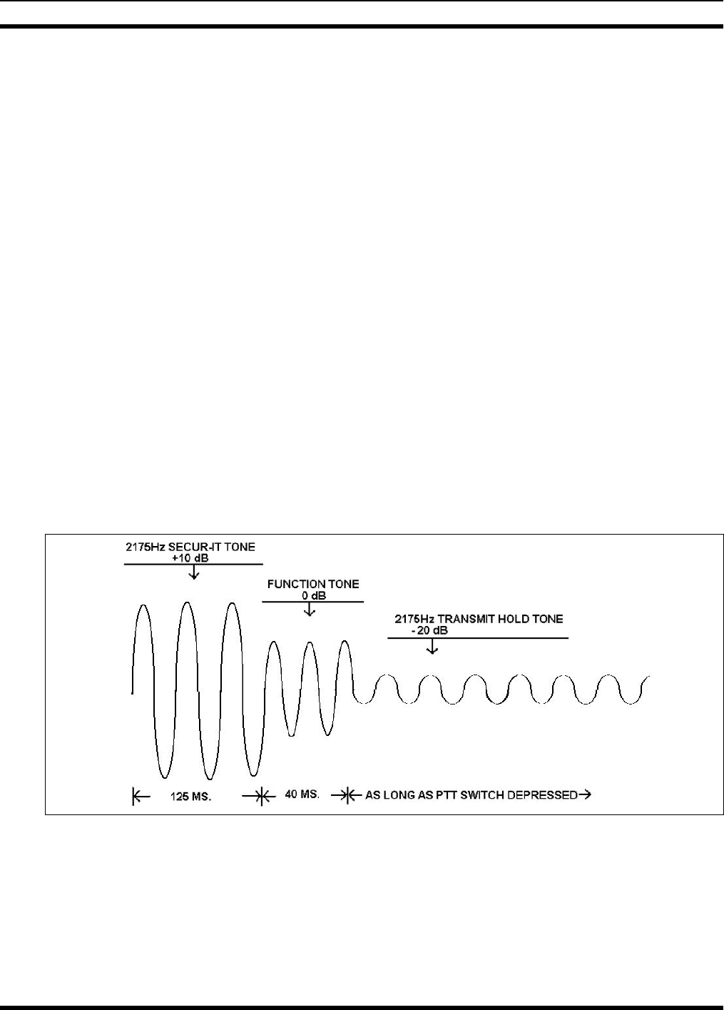
MM102558V1 R1A
5.6.9.3 Tone Remote
In tone remote applications, the T/R Shelf uses the System Module and its onboard Digital Signal
Processor (DSP) to interface with a Tone Remote control unit through a two-wire or four-wire phone line.
A MASTR III ADC station may be programmed to allow Tone Remote control of the following
functions:
• Repeater Enable (disable)
• Channel Guard Decode Enable (disable)
• Channel Guard Monitor
• Transmit Frequency Selection
• Receive Frequency Selection
• Scan
• Receiver Selection (Auxiliary Receiver selection)
• Auxiliary Output Enable (disable) (Auxiliary Control)
Signaling from a Tone Remote control unit consists of a high level Secur-it tone, followed by the
appropriate medium level function tone (as well as a hold tone if the transmitter is keyed). The tone
control sequence is shown in Figure 5-3.
The Secur-it tone is a +10 dB, 2175 Hz tone that is present for 125 milliseconds. The Secur-it tone is
followed by a 40 millisecond, 0 dB Function tone. The Function tone can be followed by a 2175 Hz Hold
tone at -20 dB level if PTT is selected. The Hold tone is present as long as the PTT is pressed.
Figure 5-3: Tone Remote Control Signaling
The frequency of the Function tone determines the function selected by a tone remote control unit.
Function tones range from 1050 Hz to 2050 Hz, and are spaced 100 Hz apart.
40

MM102558V1 R1A
Table 5-1: Typical* Tone Functionality for Tone Remote Control Signaling
TONE
(Hz) FUNCTION TONE
(Hz) FUNCTION
2175 SECUR-IT / TX Hold 1550 Channel Guard Decode or Repeater Enable
2050 RX Channel Guard Disable (Reset by
PTT) 1450 Channel Guard Decode OFF or Repeater
Disable
1950 TX Freq. No. 1 1350 TX-Freq. No. 3 or Aux. Function 1 ON
1850 TX Freq. No. 2 1250 TX-Freq. No. 4 or Aux. Function 1 OFF
1750 TX Freq. No 1 or Receiver No. 1 1150 Repeater Enable**
1650 TX Freq. No 2 or Receiver No. 2 1050 Repeater Disable** or Scan Simultaneous
Monitor
* The functionality listed for each tone is typical, however may differ for some installations.
** Repeater Enable and Repeater and disable are 1150 Hz and 1050 Hz only when Channel Guard
ON/OFF is present.
5.6.10 Auxiliary Control Relay
The MASTR III ADC T/R shelf may be equipped with up to two optional auxiliary relay kits, identified
as K1 and K2. Assignment of control functions for each relay may be performed using MSEDIT
Programming software.
AUX1 relay (K1) and AUX2 relay (K2) each contain two Form-C contacts and operate under remote
control. When AUX1 function is started, the system microprocessor sets signal RXF3/AUX1 to logic
high which switches K1. When AUX2 function is started, the system microprocessor sets bit 4 of output
register U106 high which switches K2. When the AUX functions are stopped, the control bits are
toggled, and the relay coil drops out. Detailed installation instructions may be found in Installation
Manual MM102554V1.
5.6.11 Squelch Operated Relay
The MASTR III ADC T/R shelf may be equipped with an optional Squelch Operated Relay (SOR),
identified as K3. The SOR (K3) contains four form "C" contacts and is rated for 2 amps at 20 VDC. The
relay operates under control of signal RX_1_MUTE, which is derived from the Carrier Activated Squelch
(CAS) signal. Detailed installation instructions may be found in Installation Manual MM102554V1.
5.6.12 Channel Guard Monitor
When the CG Monitor function DC control current or tone is received from a remote control unit, the T/R
Shelf does not require the correct CG before un-muting the receiver. This allows received audio to be
passed down the line to a remote control unit regardless of CG content, allowing the remote operator to
monitor all frequency activity prior to transmitting. For repeater stations, the correct CG tone(s) are still
required to key the station in repeat mode. This function is automatically reset when a remote control unit
keys the transmitter.
41

MM102558V1 R1A
5.6.13 System Module - Digital Signal Processing
The System Module also employs a State-of-the-Art audio Digital Signal Processing (DSP).
Audio DSP is used to improve audio clarity, provide consistent audio leveling and enhanced tone
generation and decoding for more flexible and reliable control functions.
The DSP provides line cancellation used during 4-wire mode to prevent unwanted signaling on
the line, notch filtering during voted applications and line audio level processing employing
compression and threshold settings.
42

MM102558V1 R1A
6 MASTR III ADC STATION DESCRIPTION
The MASTR III ADC base station may be equipped to operate in the VHF, UHF or 800 MHz band. The
station equipment is designed to install into a 19 inch wide rack mount equipment cabinet or rack. The
station can be equipped with a wide range of modules and accessories to meet a diverse range of system
requirements including simplex, half duplex, duplex and transmit-only frequency operation. Modulation
schemes include Frequency Modulated (FM) analog and digital modulation. Stations may be equipped as
a single stand-alone unit or as a multiple station installation including antenna combining and
multiplexing techniques.
The basic set of MASTR III ADC base station equipment consists of the following:
• MASTR III ADC T/R Shelf
• RF Power Amplifier
MASTR III ADC base stations are available with various combinations of the following equipment:
• Station Power Supply
• Antenna Switch
• TX/RX Antenna Duplexer
• TX Combiners and RX Multicouplers
• 37” and 83” Cabinets, and 86” Open Rack
6.1 MASTR III ADVANCED DIGITAL CAPABLE T/R SHELF
The ADC Transmitter/Receiver (T/R) Shelf provides housing and interconnection for the RF and control
modules. Figure 6-1 shows a typical MASTR III ADC T/R shelf with the basic set of modules required
for basic Conventional FM transmit and receive applications. Additional modules are available for TX
Data requirements, RX audio multi-path filtering, and Conventional P25 applications.
The T/R Shelf is comprised of a 19 inch rack mountable enclosure, an Interface board and a Backplane
board to interconnect each module. The T/R shelf may be populated with various TX, RX, power and
control modules. The function of each module is briefly described in the following sections.
The plug-in modules available for Conventional applications include:
• TX Synthesizer Module • System Module
• RX Synthesizer Module • Adaptive Multi-Path Filter Module
• RX Front End Module • Data Module
• RX IF Module • DSP Module
• Power Module (DC)
43
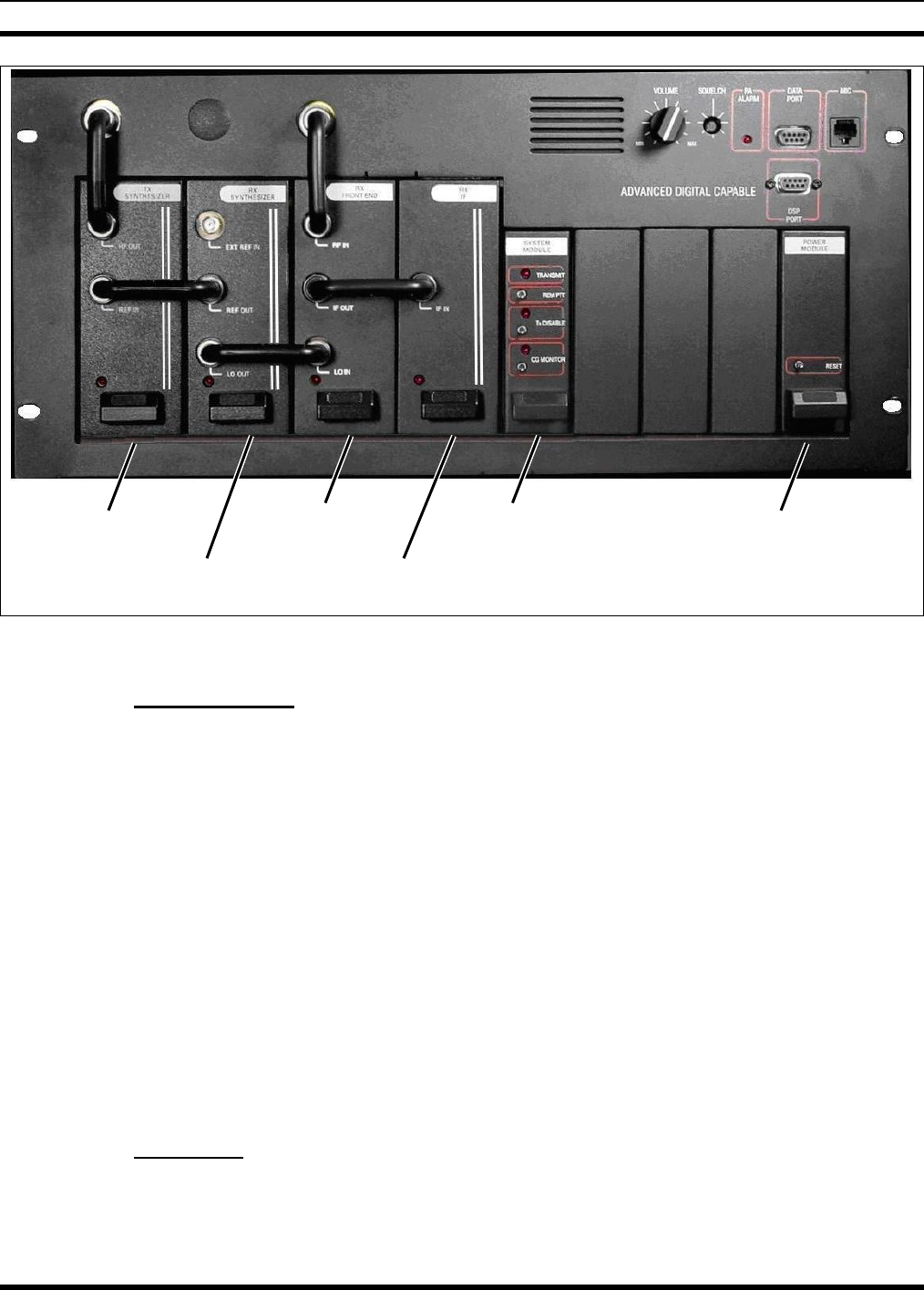
MM102558V1 R1A
Transmit
Synthesizer
Receiver
Synthesizer
Receiver
Front End System
Module
Receiver IF
Power
Module
Figure 6-1: Advanced Digital Capable T/R Shelf (Equipped for Conventional FM)
6.1.1 Interface Board
The Interface Board 19D902975, shown in Figure 6-2, is mounted in the top of the ADC T/R shelf and
provides the interface between the System Module and the RF Modules, and performs the following
functions:
• Control Interface from System Module to RF Modules.
• Telephone line interface with current level detection for remote control.
• Audio PA for local speaker.
• Transmitter power output level and control.
• Manual adjustment with front panel access of receiver squelch and local speaker volume.
• LED indication of PA Alarm.
• Various connectors including RS232 programming port and Mic/Handset port.
• Alarm and monitor junctions of PA output power for MASTR III applications.
6.1.2 Backplane
The Backplane Board CB101126V1, shown in Figure 6-2, is used to interconnect power, low level audio,
IF and data signaling between the MASTR III RF, Power and System Modules.
44
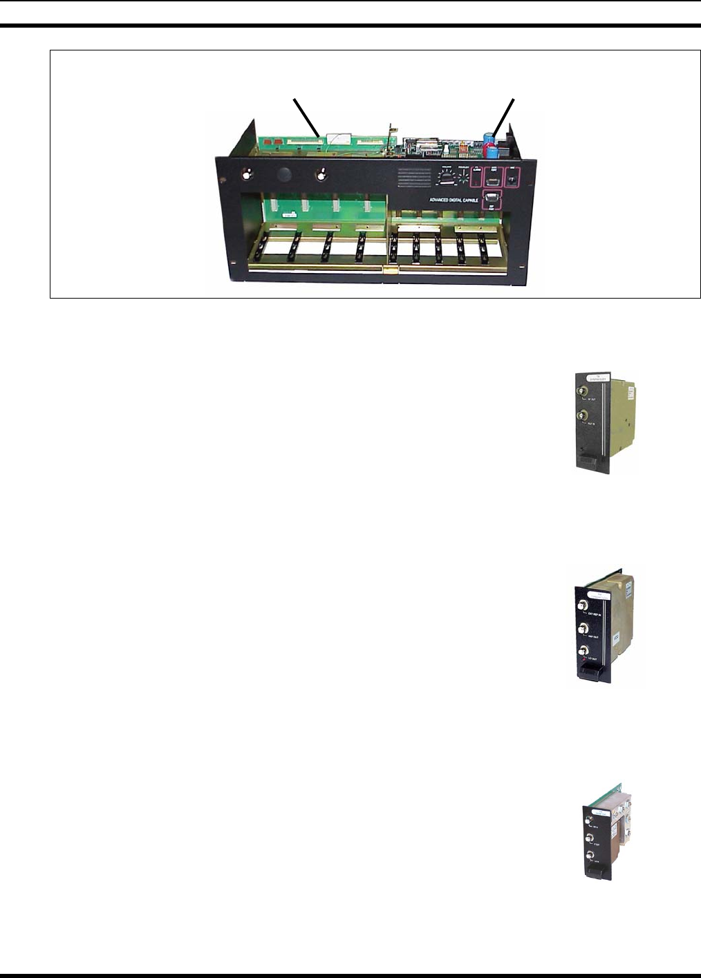
MM102558V1 R1A
Interface
Board
Backplane
Figure 6-2: MASTR III ADC T/R Shelf Backplane and Interface Board
6.1.2.1 Transmitter Synthesizer Module
The Transmitter Synthesizer Module (TX SYN) model EA101685, shown
in Figure 6-3, provides the RF excitation for the input of the base station
RF Power Amplifier.
The output of the TX synthesizer is a Frequency-Modulated (FM) signal
and derives its reference oscillator signal from either the Receiver
Synthesizer Module or Data Module in Transmit-Only base stations. Figure 6-3: Transmitter
Synthesizer Module
6.1.2.2 Receiver Synthesizer Module
The Receiver Synthesizer (RX SYN) module EA101684, shown in
Figure 6-4, generates a Phase Locked Loop (PLL) Local Oscillator (LO)
signal used by the Receiver Front End Module in the ADC T/R Shelf.
The Synthesizer Module follows operational and frequency determining
instructions from the System Module to select between an external or
internal reference oscillator which provides a highly stable reference for
the PLL to operate. The Receiver Synthesizer Module also provides the
selected reference oscillator signal to the Transmitter Synthesizer Module. Figure 6-4: Receiver
Synthesizer Module
6.1.2.3 Receiver Front End Module
The Receiver Front End (RxFE) Module 19D902782, shown in
Figure 6-5, provides Front End band pass tuning capable of passing the
desired receiver frequency while providing first L.O. image rejection and
L.O. signal isolation at the antenna port. The RxFE also mixes the RF
signal from the band pass circuit with the Receiver Synthesizer signal to
create the First Intermediate Frequency (IF) signal, 21.4 MHz for VHF
and UHF systems, and 70.2 MHz for 800 MHz systems. Finally, the First
IF signal is passed to the receiver IF module. Figure 6-5: Receiver
Front End Module
45

MM102558V1 R1A
6.1.2.4 Receiver IF Module
The Receiver IF (RX IF) module models EA101401V1 (21.4 MHz for
VHF and UHF stations) and EA101794V1 (70.2 MHz for 800 MHz
stations), shown in Figure 6-6, provides IF filtering, amplification, and
demodulation of the IF signal.
Output signals from the IF modules include a balanced 455 kHz IF
output for data applications and a demodulated audio output for analog
audio applications. The IF Module also provides AGC for the 455 kHz
IF signal and includes the receiver squelch circuitry.
Figure 6-6: Receiver IF
Module
6.1.2.5 System Module
The System Module 19D902590G6, shown in Figure 6-7, uses
programmable microcomputer technology to control the base station's
transmitter, receiver, and audio processor. This module contains a Digital
Signal Processor (DSP) used for audio processing, tone generation and
detection.
The System module can be programmed for up to twelve (12) channel
operation during local control or programmed for remote control
applications. DC remote control features can control up to two (2)
transmit and receive frequencies, while Tone remote control can control
up to four transmit and receive frequencies.
Options provided by the Control Section include a transmitter Drop-Out
Delay (DOD) timer, Carrier Control Timer (CCT), Channel Guard (CG),
and Squelch Operated Relay output (SOR). The CCT is programmable
from zero to 10 minutes. The DOD is programmable from zero to 10
seconds. Additional station options include:
• Battery alarm tone
• Type 90 or DTMF tone decoding
• 2/4 wire audio
• Morse code station identification
• Auxiliary control
Figure 6-7: System
Module
46
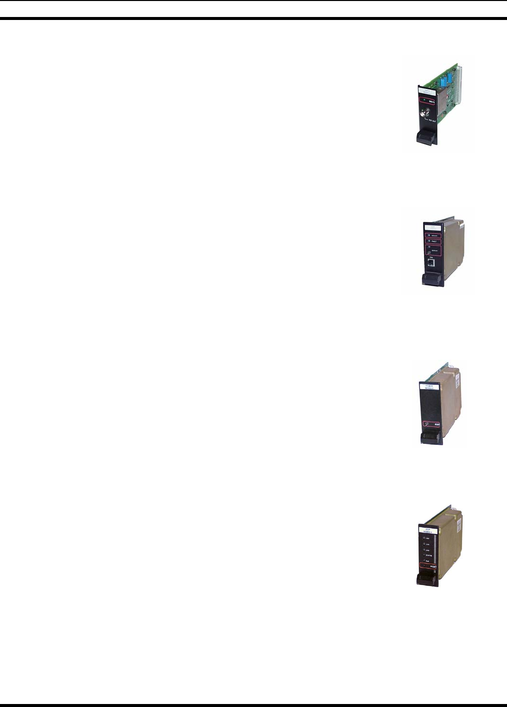
MM102558V1 R1A
6.1.2.6 Data Module
Data Module 19D904558, shown in Figure 6-8, allows the MASTR® III
Base Station to transmit Non Return to Zero (NRZ) data such as those
produced by paging systems.
The Data Module accepts data with rates up to 9600 baud within a range
of -25V to +25V. The Data Module produces two corresponding outputs;
a modulated 12.8 MHz reference signal to drive the Reference Input of
the Transmit Synthesizer, and filtered audio data that modulates the audio
input of the Transmit Synthesizer. Together these modulation sources
produce a clean data pattern resulting in reliable data transmissions. Figure 6-8: Data Module
6.1.2.7 AMPF Module
AMPF Module KRG 101 56/1, shown in Figure 6-9, is a self-contained
DSP-based plug-in module capable of filtering audible low frequency
pops out of the base station’s received audio signal.
The module executes a proprietary DSP algorithm that reduces the audible
pops primarily caused by the reception of reflected or multi-path RF
signals because of an affect known as Rayleigh distribution or Rayleigh
fading. Figure 6-9: AMPF
Module
6.1.2.8 Power Module
The Power Module 19D902589G2, shown in Figure 6-10, provides
power to the T/R shelf and modules. It contains switching regulators for
the +5V, +12V, and -12V DC supplies. The output of the +12V and -
12V supplies are further regulated to provide +5V and -5V required by
the analog components.
Figure 6-10: Power Module
6.1.2.9 DSP Module
The DSP Module EA101800V1, shown in Figure 6-11, The DSP Module
provides the necessary processing to generate and decipher the outbound
and inbound P25 signaling.
The DSP module extracts P25 intelligence from the 455 kHz Receiver IF
data output and forms it into two outputs, the High Speed Data (HSD)
output and a serial output. The HSD output is passed to the System
Module for re-transmission and the serial data is routed to a Station
SitePro for conversion to IP packets or other formats for remote
applications.
The DSP Module also encodes incoming data from the Station SitePro
and analog inputs into P25 data and passes it to the System Module. The
DSP Module allows the MASTR III P25 station to support the TIA 102
P25 Clear Air interface (CAI) protocol.
Figure 6-11: DSP Module
47
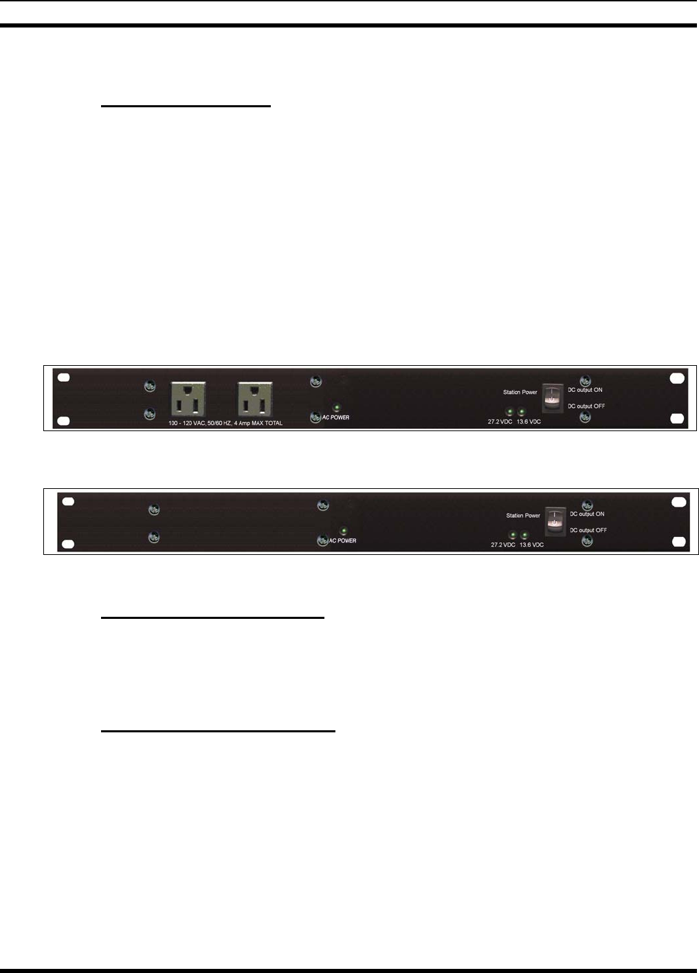
MM102558V1 R1A
6.2 STATION EQUIPMENT
6.2.1 Station Power Supply
The MASTR III ADC station is available with either of two models switching power supply. The
PS103010 (120 VAC input), shown in Figure 6-12, and the PS24043-0001 (240 VAC input), shown in
Figure 6-13, are Multi-Output; AC to DC Switching Power Supplies housed in a metal chassis with built-
in dual cooling fans. The supplies replace the previous model 19A149979 series 120V and 240V power
supplies.
Both the PS103010 and PS24043-0001 switching power supplies are 600 Watt continuous duty power
supply with two independent voltage outputs for full station operation, and includes a built-in battery
back-up system. A 27.2 VDC output at 15 Amperes provides power to the RF Power Amplifier while a
13.6 VDC output at 6 Amperes provides power to the MASTR III ADC system (T/R) shelf. The battery
back-up circuit includes a built-in battery charging circuit to maintain maximum battery performance.
The supply incorporates features for over-voltage and over-current protection, 24V status signaling, and a
forced-air cooling system for optimal system performance.
Figure 6-12: 120 VAC Switching Power Supply
Figure 6-13: 240 VAC Switching Power Supply
6.2.2 DC Power Distribution Panel
A DC Power Distribution panel is available for the MASTR III ADC station. This DC panel provides a
high current 24 VDC input connection, and a low current 12 VDC input connection from external DC
power sources. The panel includes safety fuses for each power source and the necessary distribution
points to power station equipment.
6.2.3 RF Power Amplifier Assembly
The RF Power Amplifier (PA) Assembly EA101292, shown in Figure 6-14, amplifies the exciter output
to rated output power level. This module contains a power module, amplifier drivers and power control
circuitry required for power amplification.
The Power Amplifier Assembly is a continuous duty, solid state, wide-band RF power amplifier. Its main
function is to amplify the 10 mW FM signal from the Transmitter Synthesizer to the rated RF output at
the antenna port. The output of the Power Amplifier Assembly is typically 110 Watts for VHF
(adjustable from 10 to 110 Watts) and 100 Watts for UHF and 800 MHz (adjustable from 10 to 100
Watts) as measured at the PA output port.
48
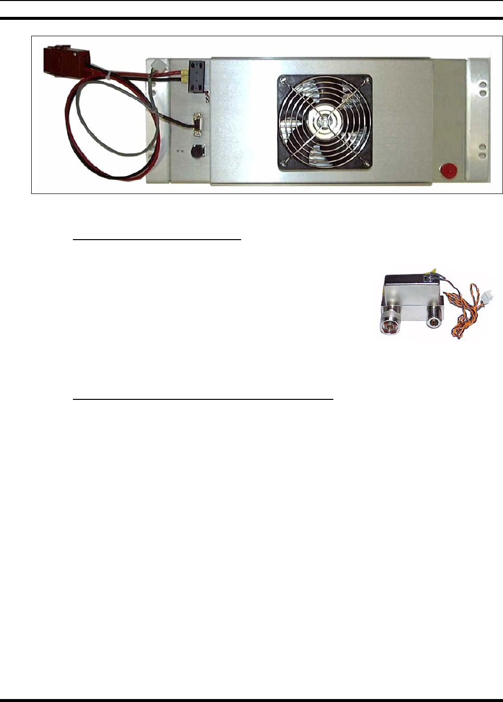
MM102558V1 R1A
Figure 6-14: RF Power Amplifier
6.2.4 RF Antenna Switch Assembly
An RF Antenna Switch assembly, shown in Figure 6-15 is available for
conventional MASTR III ADC stations operating in the simplex or half-
duplex base station mode.
The Antenna Switch is available with or without mounting hardware and
cabling. Mounting hardware options are available for mounting the
Antenna Switch either directly to the RF PA assembly or as a 19” rail
mounted device.
Figure 6-15: Antenna
Switch
6.2.5 Cabinet Enclosures and Open Rack Assembly
MASTR III ADC station equipment is typically installed in a steel cabinet or rack, however may be
ordered without a cabinet or rack. Cabinet enclosures include front and rear doors for full station access.
Also available is an indoor open rack and a weatherproof outdoor cabinet.
The following list defines the available cabinet sizes, styles, and number of MASTR III ADC stations that
can be installed into each type of cabinet or rack, dependent upon the hardware options installed in
conjunction with each station:
• 37" Indoor Cabinet (1 station per cabinet)
• 45” Weatherproof Outdoor Cabinet (1 station per cabinet)
• 69” Indoor Cabinet (1-4 stations per cabinet)
• 83" Cabinet (1-5 stations per cabinet)
• 86" Open Rack (1-5 stations per rack)
49

M/A-COM Wireless Systems
221 Jefferson Ridge Parkway
Lynchburg, Virginia 24501
(Outside USA, 434-385-2400) Toll Free 800-528-7711
www.macom-wireless.com Printed in U.S.A.