Realtek Semiconductor RTL8188CE 802.11b/g/n RTL8188CE User Manual II
Realtek Semiconductor Corp. 802.11b/g/n RTL8188CE II
Contents
user manual II
26
3 Getting Started
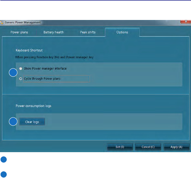
Options
Options allows the user additional functions:
1
2
1
Choose what action you want your PC to take when [Fn] + the Power Manager
key is pressed.
2
You can clear your power consumption logs here.
27
Getting Started 3
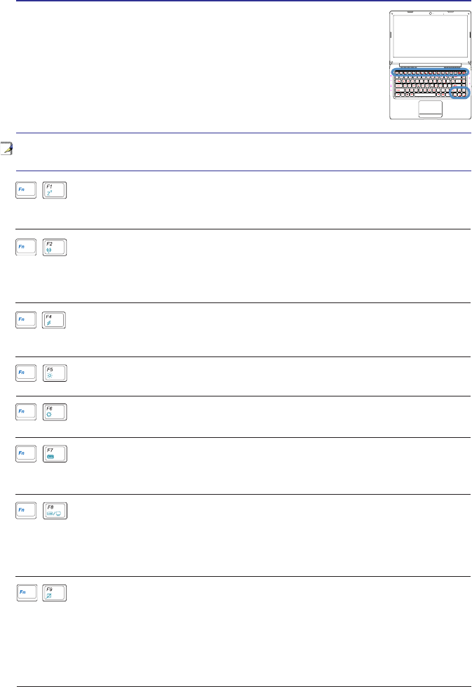
Special Keyboard Functions
Colored Hot Keys
pressing and holding the function key while pressing a key with a
colored command.
NOTE: The Hot Key locations on the function keys may vary depending on model
but the functions should remain the same.
“Zz” Icon (F1): Places the Notebook PC in suspend mode (either Save-
to-RAM or Save-to-Disk depending on sleep button setting in power
management setup).
Dim Sun Icon (F5):
Decreases the display brightness
Bright Sun Icon (F6):
Increases the display brightness
LCD Icon (F7): Toggles the display panel ON and OFF. (On certain
low resolution modes.)
LCD/Monitor Icons (F8): Toggles between the Notebook PC’s LCD display
and an external monitor in this series: Notebook PC LCD -> External
Monitor -> Both. (This function does not work in 256 Colors, select High
Color in Display Property Settings.) NOTE: Must connect an external
monitor “before” booting up.
Radio Tower Icon (F2): Wireless Models Only: Toggles the internal
wireless LAN ON or OFF with an on-screen-display. When enabled, the
corresponding wireless indicator will light. Windows software settings
are necessary to use the wireless LAN.
Lightning Icon (F4): Toggles the notebook PC between various power
mannagement modes. The power management modes control many
aspects of the device to maximize performance versus battery time.
(continued on the next page)
Crossed-out Touchpad (F9): Toggles the built-in touchpad LOCKED
(disabled) and UNLOCKED (enabled). Locking the touchpad will prevent
you from accidentally moving the cursor while typing and is best used with
an external pointing device such as a mouse. NOTE: Selected models have
an indicator between the touchpad buttons will light when the touchpad
is UNLOCKED (enabled) and not light when the touchpad is LOCKED
(disabled).
28
3 Getting Started
Colored Hot Keys (cont.)
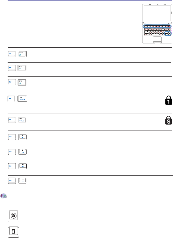
Microsoft Windows Keys
There are two special Windows keys on the keyboard as described below.
The key with the Windows Logo activates the Start menu located at the
bottom left of the Windows desktop.
The other key, that looks like a Windows menu with a small cursor, activates
the properties menu and is equivalent to pressing the right mouse button
on a Windows object.
Speaker Up Icon (F12):
Increases the speaker volume (only in Windows OS)
Speaker Down Icon (F11):
Decreases the speaker volume (only in Windows OS)
Speaker Icons (F10):
Toggles the speakers ON and OFF (only in Windows OS)
Stops a media player during playback.
Plays or pauses media in the media player.
Moves the media to the previous section/track during playback.
Moves the media to the next section/track during playback.
Scr Lk (Del): Toggles the “Scroll Lock” ON and OFF. Allows you to
use a larger portion of the keyboard for cell navigation.
Num Lk (Ins): Toggles the numeric keypad (number lock) ON and
OFF. Allows you to use a larger portion of the keyboard for number
entering.

29
NOTE: Photos and icons in this document are used for artistic purposes only and do
not show what is actually used in the product itself.
4. Using the Notebook PC
Pointing Device
Storage Devices
Connections
30
4 Using the Notebook PC
IMPORTANT! Do not use any objects
touchpad or else damage may occur
to the touchpad’s surface.
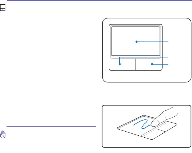
Pointing Device
Using the Touchpad
all that is required to operate the touchpad.
Because the touchpad is electrostatic
sensitive, objects cannot be used in
primary function is to move the cursor
around or select items displayed on
instead of a standard desktop mouse.
The following illustrations demonstrate
proper use of the touchpad.
Moving The Cursor
touchpad and slide in a direction to move
the cursor.
Cursor
Movement
Right Click
Left Click
31
Using the Notebook PC 4
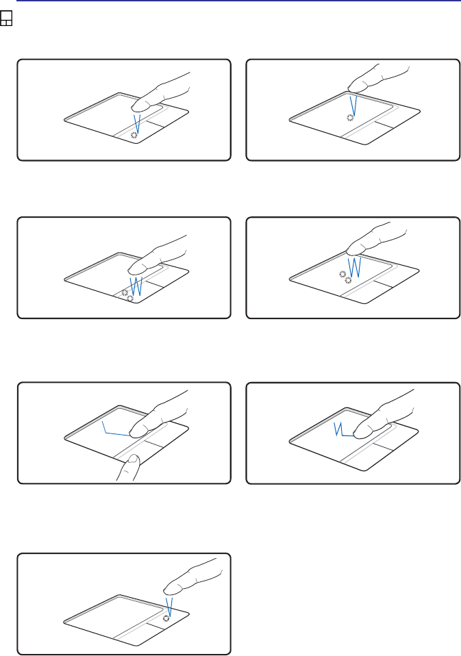
Touchpad Usage Illustrations
Press the left cursor button and release. Lightly but rapidly strike the touchpad.
Clicking Function
Press the right cursor button and
release.
Right-Clicking Function
Press the left button twice and release. Lightly but rapidly strike the touchpad
twice.
touchpad.
Lightly strike the touchpad twice, sliding
Double-Clicking Function
Dragging-Clicking Function
32
4 Using the Notebook PC
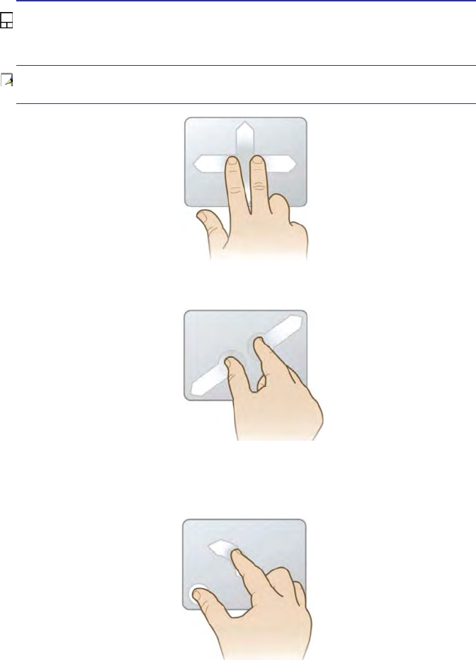
Multi-touch gesture usage
Multi-touch recognizes multiple simultaneous touch points to allow advanced software
TIP: For detailed gesture usage, please refer to the video demonstration in “Mouse
Properties” > “Device Settings”
Two Finger Scrolling
Two Fingers Pinch Zoom
Convenient for viewing photos.
Pivot Rotate
an on-screen item in 90-degree increments.
33
Using the Notebook PC 4
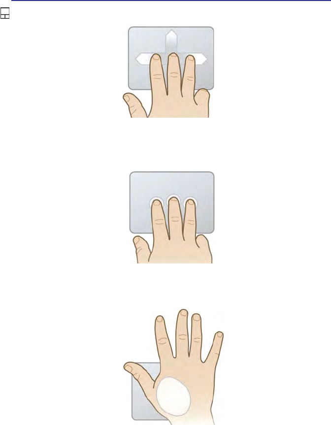
Multi-touch gesture usage (cont.)
Three Finger Flick
application used.
Three Finger Press and Hold
Functions depend on the notebook model used.
Palm Press and Hold
Press, hold, then release the heel of your thumb on the touchpad for enhanced
functions. Functions depend on the notebook model used.

34
4 Using the Notebook PC
NOTE: The touchpad responds to movement not to force. There is no need to tap
the surface too hard. Tapping too hard does not increase the responsiveness of the
touchpad. The touchpad responds best to light pressure.
Caring for the Touchpad
The touchpad is pressure sensitive. If not properly cared for, it can be easily
damaged. Take note of the following precautions.
35
Using the Notebook PC 4
IMPORTANT! Never remove cards while or immediately after reading, copying,
formatting, or deleting data on the card or else data loss may occur.
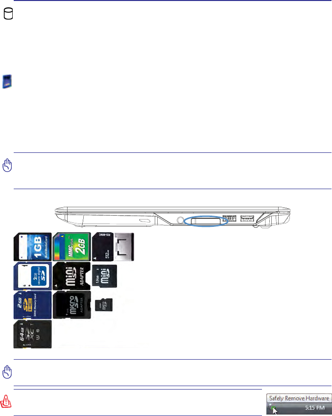
Flash Memory Card Reader
Normally a memory card reader must be purchased separately in order to use
memory cards from devices such as digital cameras, MP3 players, mobile phones,
and PDAs. This Notebook PC has a built-in memory card reader that can use many
is not only convenient, but also faster than most other forms of memory card readers
because it utilizes the internal high-bandwidth PCI bus.
IMPORTANT! Flash memory card compatibility varies depending on Notebook PC
constantly change so compatibility may change without warning.
Flash Memory Card Examples
WARNING! To prevent data loss, use “Windows Safely Remove
SD (Secure Digital)
miniSD (with SD adapter)
SDHC (Secure Digital High Capacity)
microSD (with SD adapter)
MMC (Multimedia Card)
MMC Plus
RS-MMC (Reduced Size) (with MMC adapter)
SDXC (Secure Digital eXtended Capacity)
Storage Devices
Storage devices allow the Notebook PC to read or write documents, pictures, and
storage devices:
36
4 Using the Notebook PC
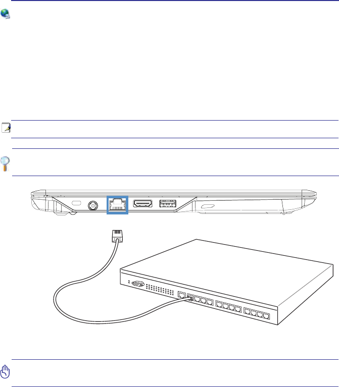
Example of the Notebook PC connected to a Network Hub or Switch for use with
the built-in Ethernet controller.
Network Connection
Connect a network cable, with RJ-45 connectors on each end, to the modem/network
port on the Notebook PC and the other end to a hub or switch. For 100 BASE-TX /
1000 BASE-T speeds, your network cable must be category 5 or better (not category
3) with twisted-pair wiring. If you plan on running the interface at 100/1000Mbps, it
must be connected to a 100 BASE-TX / 1000 BASE-T hub (not a BASE-T4 hub).
For 10Base-T, use category 3, 4, or 5 twisted-pair wiring. 10/100 Mbps Full-Duplex
is supported on this Notebook PC but requires connection to a network switching
hub with “duplex” enabled. The software default is to use the fastest setting so no
user-intervention is required.
1000BASE-T (or Gigabit) is only supported on selected models.
Network Hub or Switch
Network cable with RJ-45 connectors
DO
NOT plug a modem cable or telephone cable into the RJ-45 (network) jack.
37
Using the Notebook PC 4
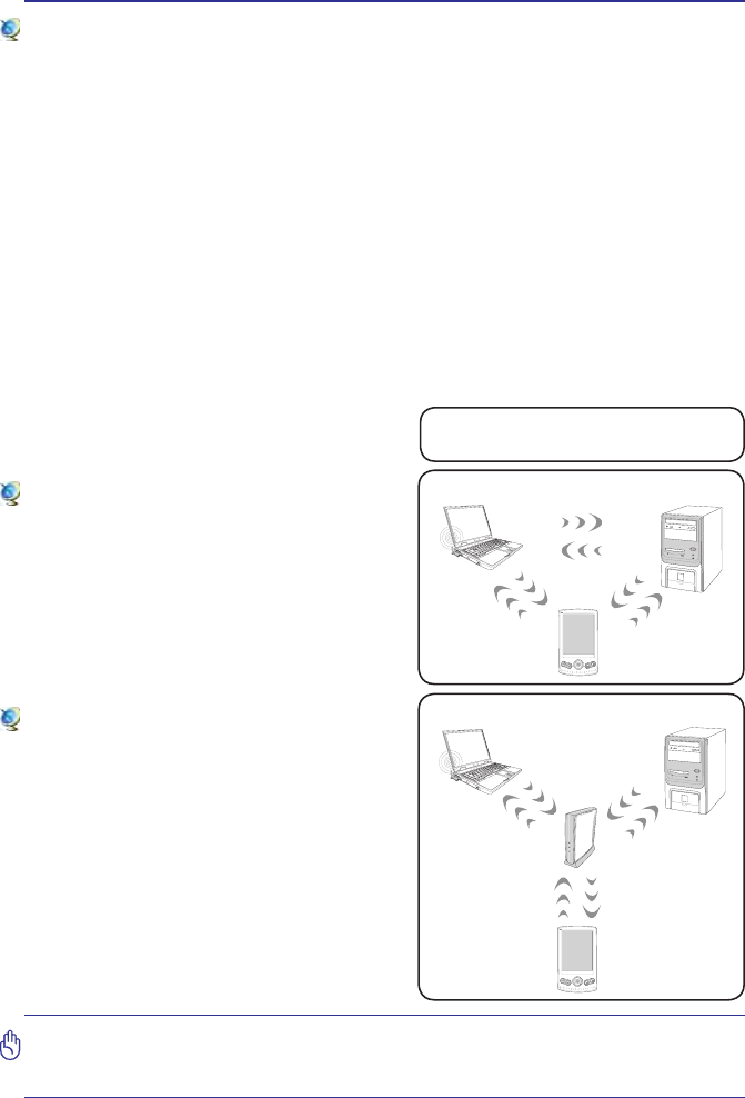
These are examples of the Notebook PC
connected to a Wireless Network.
Desktop PC
PDA
Notebook PC
Access
Point
Desktop PC
PDA
Notebook PC
Wireless LAN Connection
The optional built-in wireless LAN is a compact easy-to-use wireless Ethernet
adapter. Implementing the IEEE 802.11 standard for wireless LAN (WLAN), the
optional built-in wireless LAN is capable of fast data transmission rates using
Direct Sequence Spread Spectrum (DSSS) and Orthogonal Frequency Division
Multiplexing (OFDM) technologies on 2.4GHz frequencies. The optional
built-in wireless LAN is backward compatible with the earlier IEEE 802.11 standards
allowing seamless interfacing of wireless LAN standards.
The optional built-in wireless LAN is a client adapter that supports Infrastructure
point.
wireless LAN comes with a 64-bit/128-bit Wired Equivalent Privacy (WEP) encryption
and Wi-Fi Protected Access (WPA) features.
Ad-hoc mode
The Ad-hoc mode allows the Notebook PC
to connect to another wireless device. No
access point (AP) is required in this wireless
environment.
(All devices must install optional 802.11 wireless LAN
adapters.)
Infrastructure mode
The Infrastructure mode allows the Notebook
PC and other wireless devices to join a
wireless network created by an Access Point
(AP) (sold separately) that provides a central
link for wireless clients to communicate with
each other or with a wired network.
(All devices must install optional 802.11 wireless LAN
adapters.)
CAUTION: DO NOT use wireless LAN on hospital premises or near a pacemaker,
doing so may cause medical devices to malfunction. DO NOT use wireless LAN on
an aircraft, as doing so may cause the aircraft’s equipment to malfunction.
38
4 Using the Notebook PC
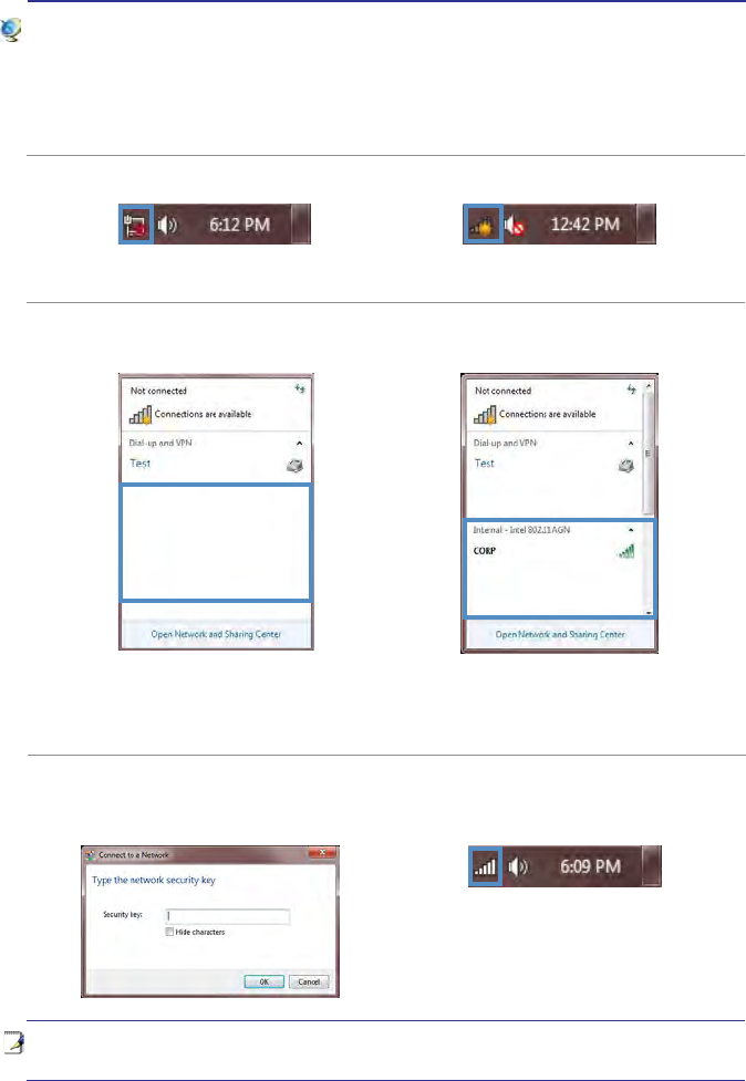
Windows Wireless Network Connection
Connecting to a network
4. When connecting, you may have to
enter a password:
1. Switch ON the Wireless function if necessary for your model (see switches and/or
special keyboard functions in Section 3).
2. A network icon will appear in the Taskbar depending on your network status:
3. Clicking on the network icon will open the network connection panel:
No connection
(Wireless function OFF)
If the wireless function on your device
has not been switched on you will see
no open connections available. Make
sure the wireless function is switched on
and try again.
Not connected
(Connections available)
Click on a connection to
connect
Connected
you see in your system.
No connection (Wireless function OFF) Not connected (Connections available)
5. When you have successfully connected
you will see the following icon in the
Taskbar:
39
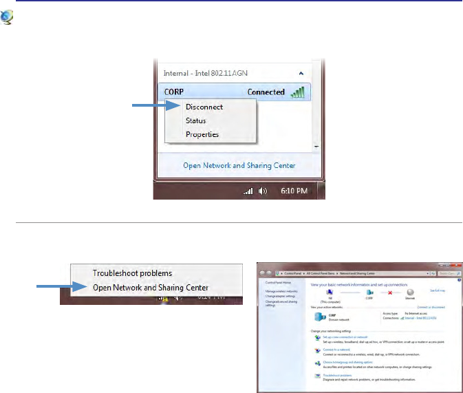
Using the Notebook PC 4
7. For more options, right-click the network icon and select the option as shown.
Windows Wireless Network Connection (cont.)
6. To disconnect, right-click the network and select the option as shown.

40
Notes

41
NOTE: Photos and icons in this document are used for artistic purposes only and do
not show what is actually used in the product itself.
A. Appendix
Declaration and Safety Statements
Federal Communications Commission Statement

42
A Appendix
Declarations and Safety Statements
Federal Communications Commission Statement
This device complies with FCC Rules Part 15. Operation is subject to the following
two conditions:
may cause undesired operation.
This equipment has been tested and found to comply with the limits for a class B digital
device, pursuant to Part 15 of the Federal Communications Commission (FCC) rules.
These limits are designed to provide reasonable protection against harmful interference
in a residential installation. This equipment generates, uses, and can radiate radio
frequency energy and, if not installed and used in accordance with the instructions, may
cause harmful interference to radio communications. However, there is no guarantee
that interference will not occur in a particular installation. If this equipment does cause
harmful interference to radio or television reception, which can be determined by turning
the equipment off and on, the user is encouraged to try to correct the interference by
one or more of the following measures:
the receiver is connected.
WARNING! The use of a shielded-type power cord is required in order to meet
FCC emission limits and to prevent interference to the nearby radio and television
reception. It is essential that only the supplied power cord be used. Use only shielded
cables to connect I/O devices to this equipment. You are cautioned that changes or
void your authority to operate the equipment.
(Reprinted from the Code of Federal Regulations #47, part 15.193, 1993. Washington
IMPORTANT: This device and its antenna(s) must not be co-located or operating in
conjunction with any other antenna or transmitter.

43
Appendix A
R&TTE Directive (1999/5/EC)
the R&TTE (Radio & Telecommunications Terminal Equipment) directive:
FCC Radio Frequency (RF) Exposure Caution Statement
This equipment complies with FCC RF exposure limits set forth for an uncontrolled
environment. To maintain compliance with FCC RF exposure compliance
requirements, please follow operation instructions in the user guide.
responsible for compliance could void the user’s authority to operate this equipment.
“The manufacturer declares that this device is limited to Channels 1 through 11 in
CE Mark Warning
This is a Class B product, in a domestic environment, this product may cause radio
interference, in which case the user may be required to take adequate measures.
RF Exposure Guidelines (SAR)
This device is in compliance with SAR for general populations/uncontrolled exposure
tested for compliance with FCC RF Exposure (SAR) limits in accordance with the
C. The equipment complies with FCC RF radiation exposure limits set forth for an
uncontrolled environment. This device was tested for operations with the device
contacted directly to the human body to the back side of the EUT.
To maintain compliance with FCC RF exposure requirements, avoid direct contact
with the antenna during transmission.