Redline Communications AN30 AN30 SYSTEM User Manual
Redline Communications Inc. AN30 SYSTEM
UserManual.wiki
>
Redline Communications
>
AN30 User Manual
users manual
Navigation menu
Upload a User Manual
Namespaces
Wiki Guide
HTML
PDF
Info
Views
User Manual
Discussion / Help
Navigation
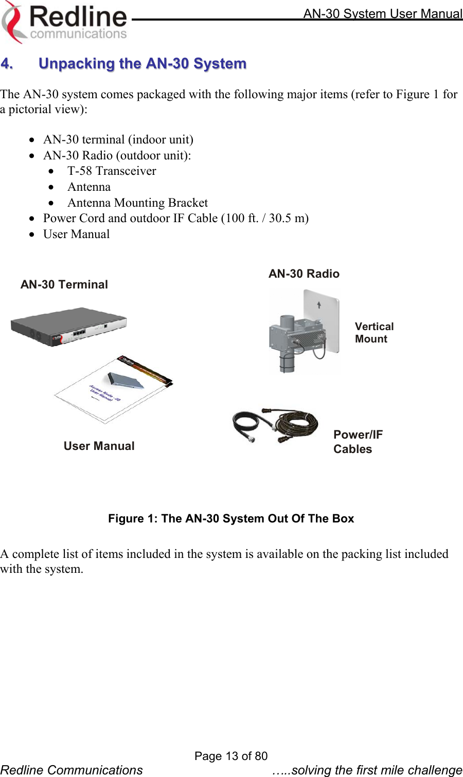
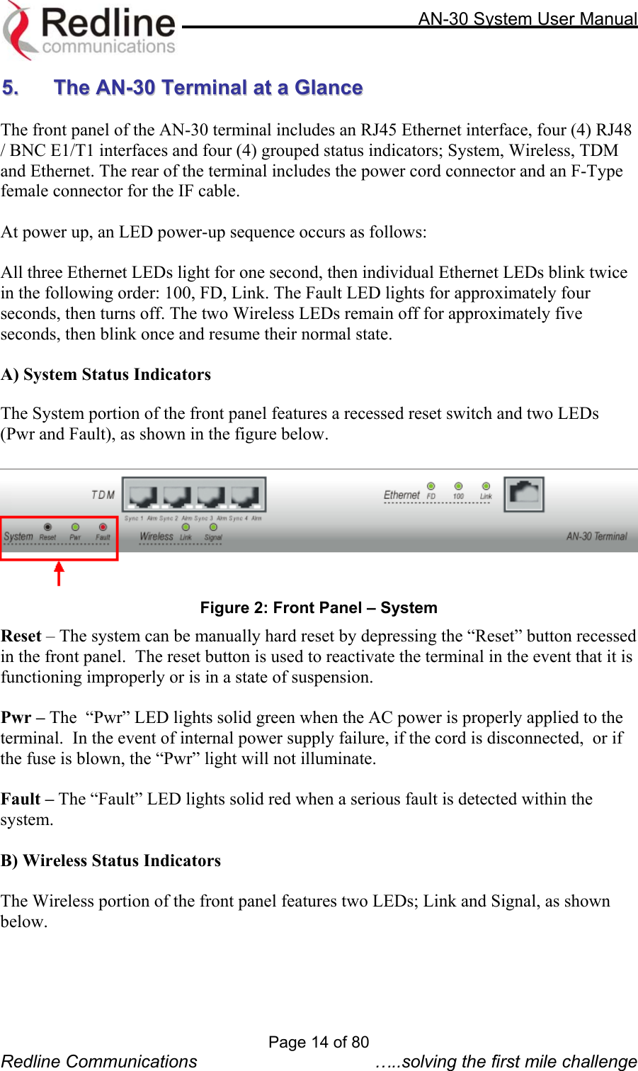
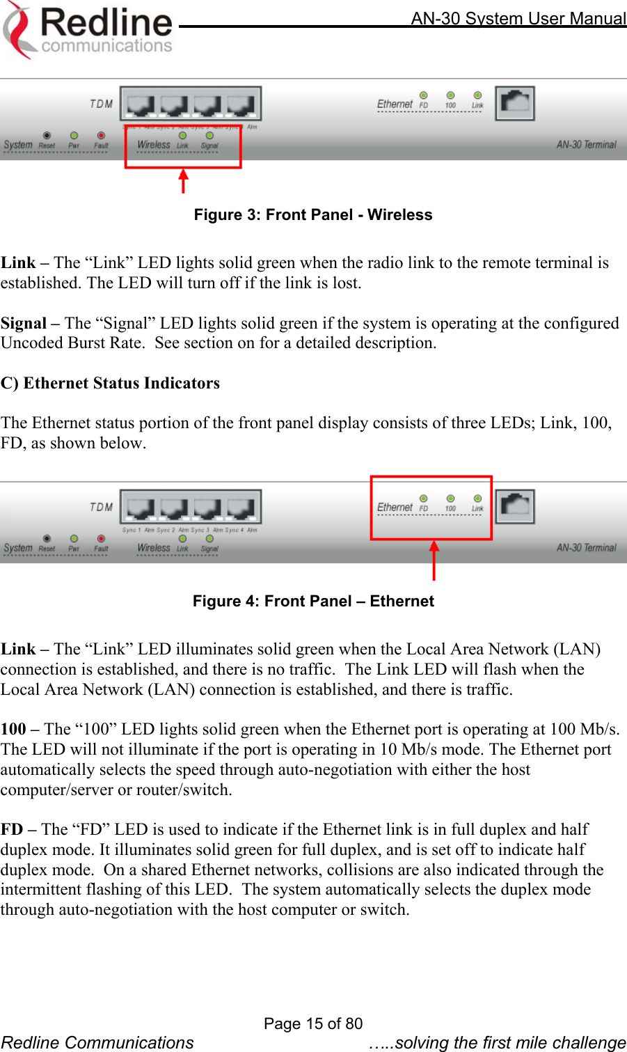
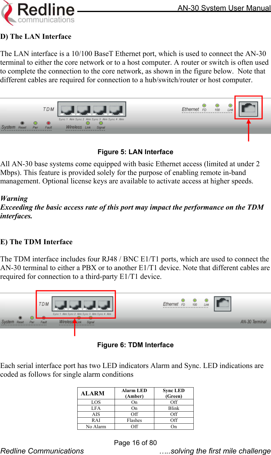
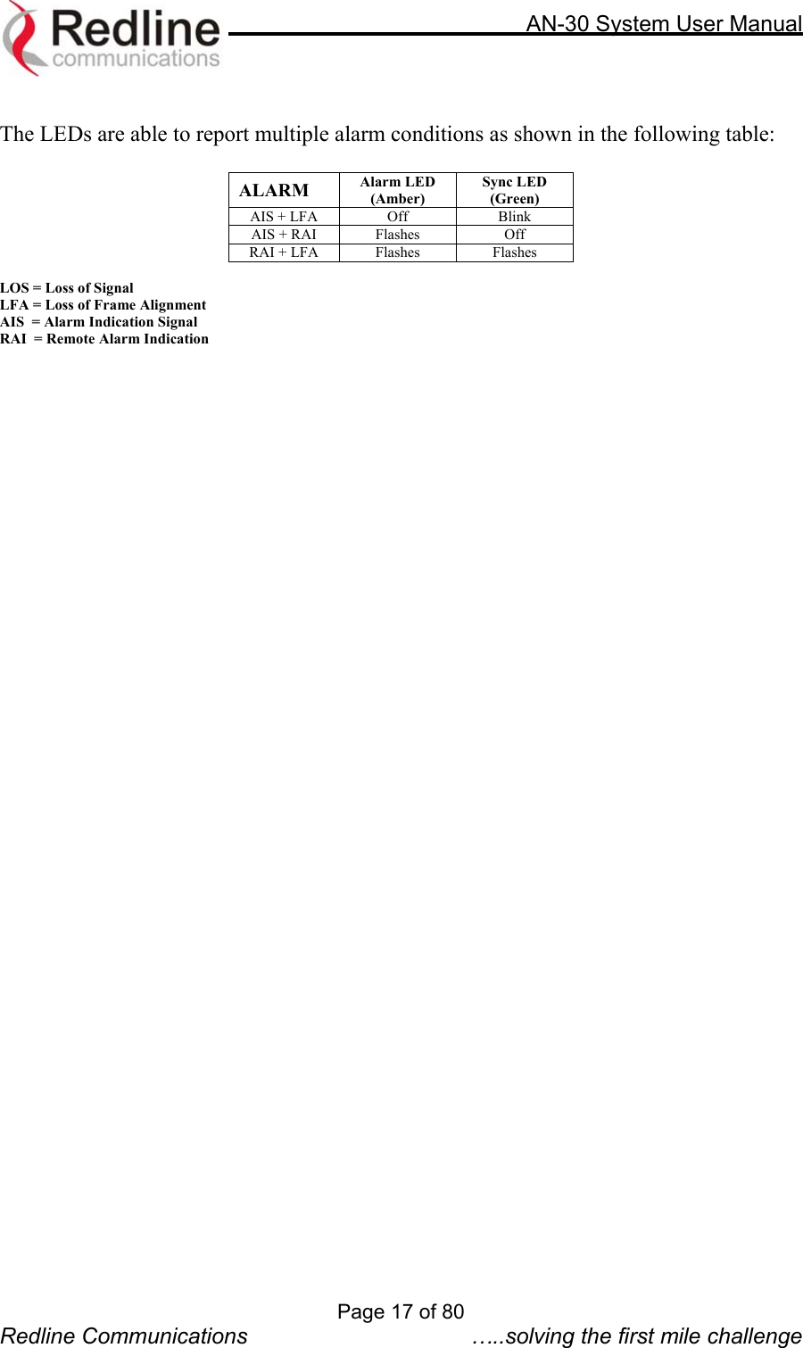
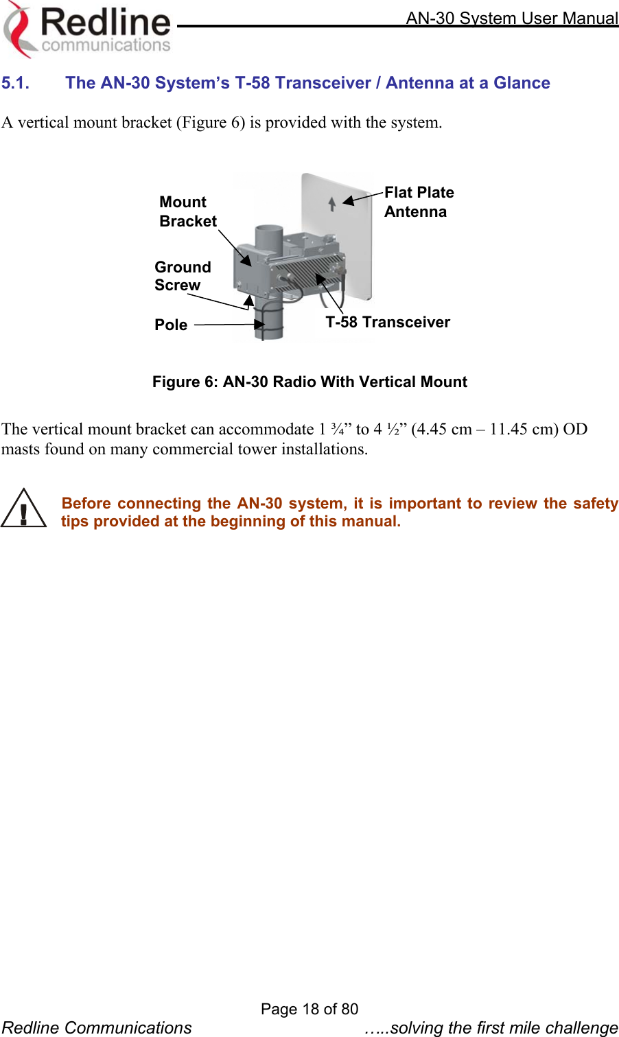
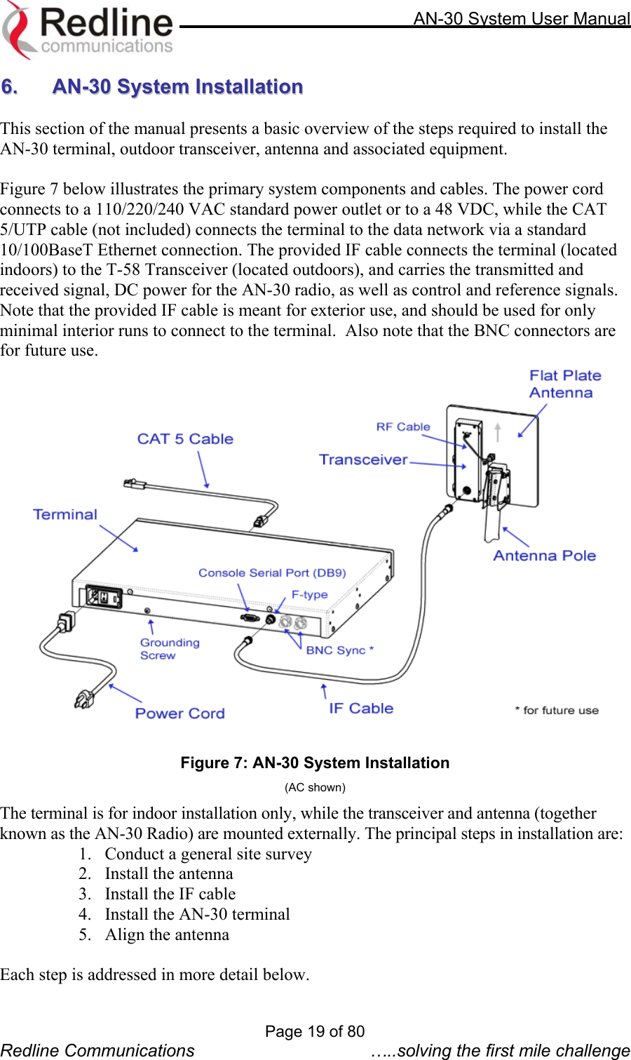
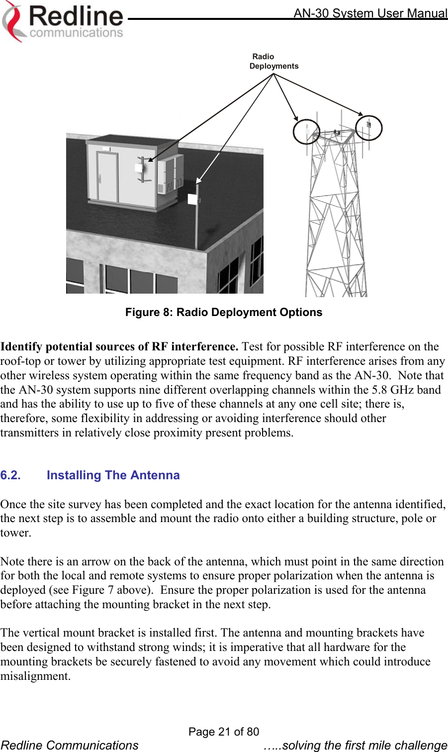
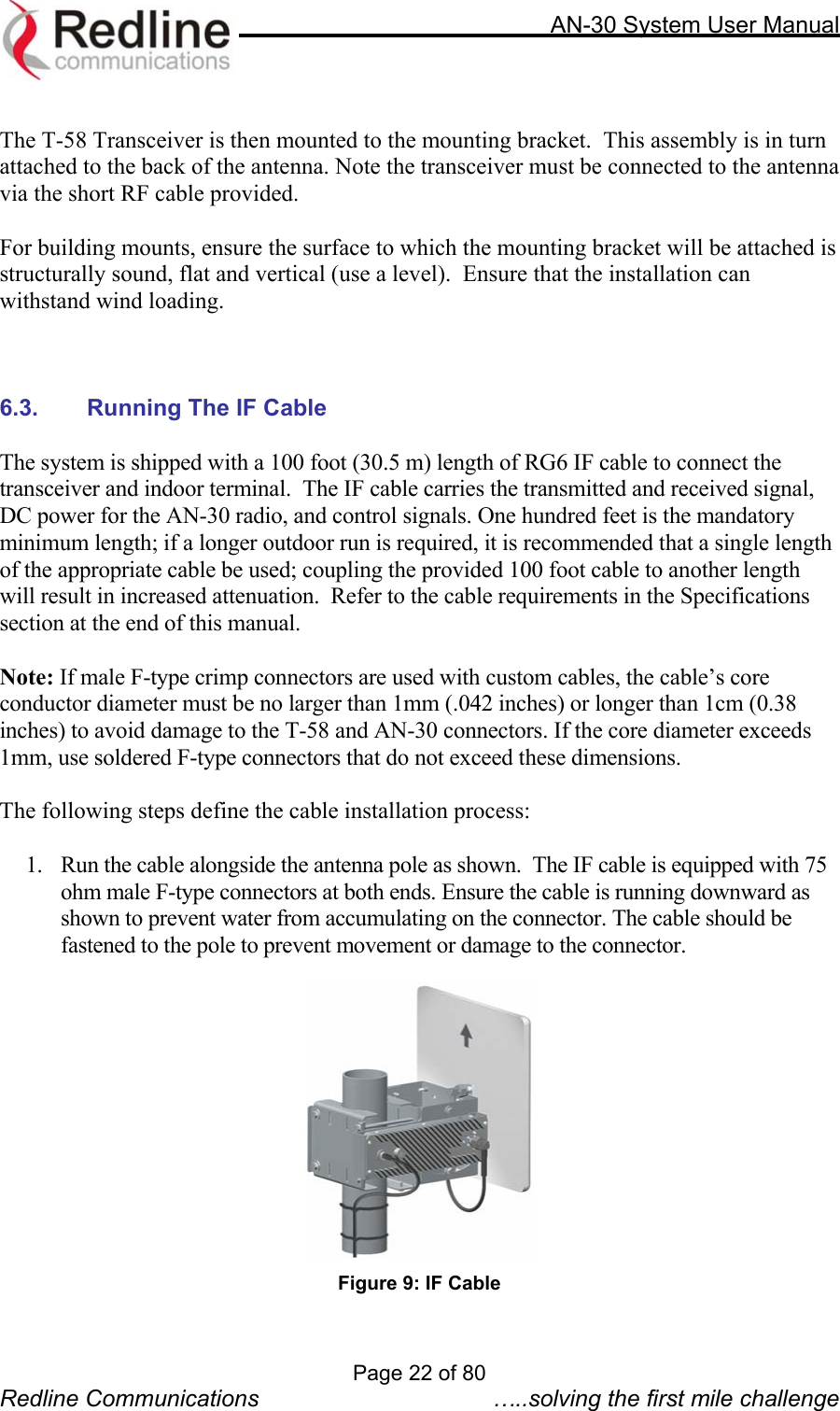
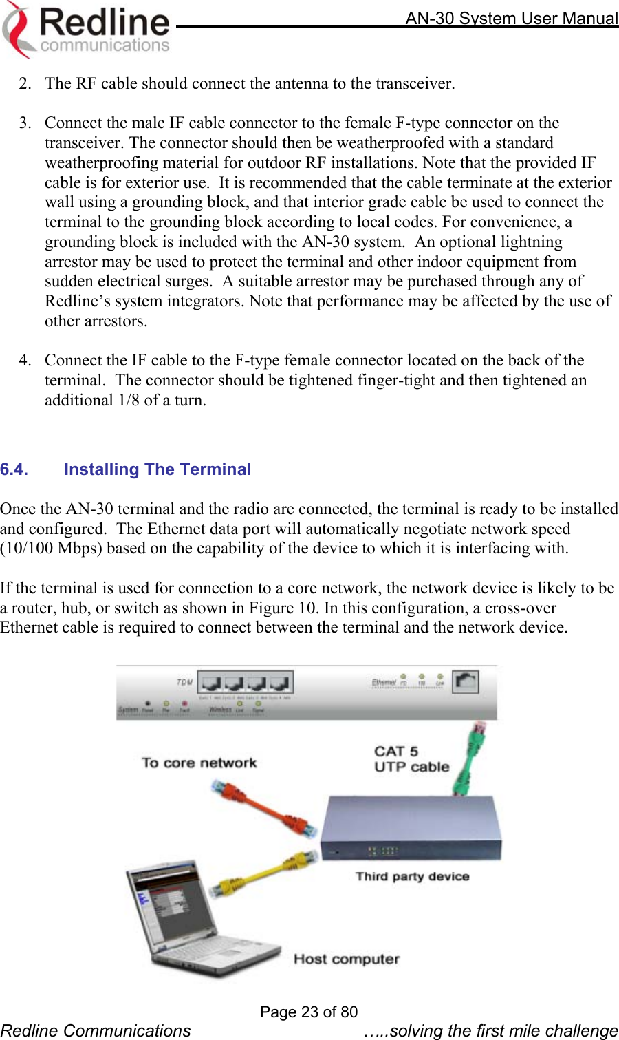
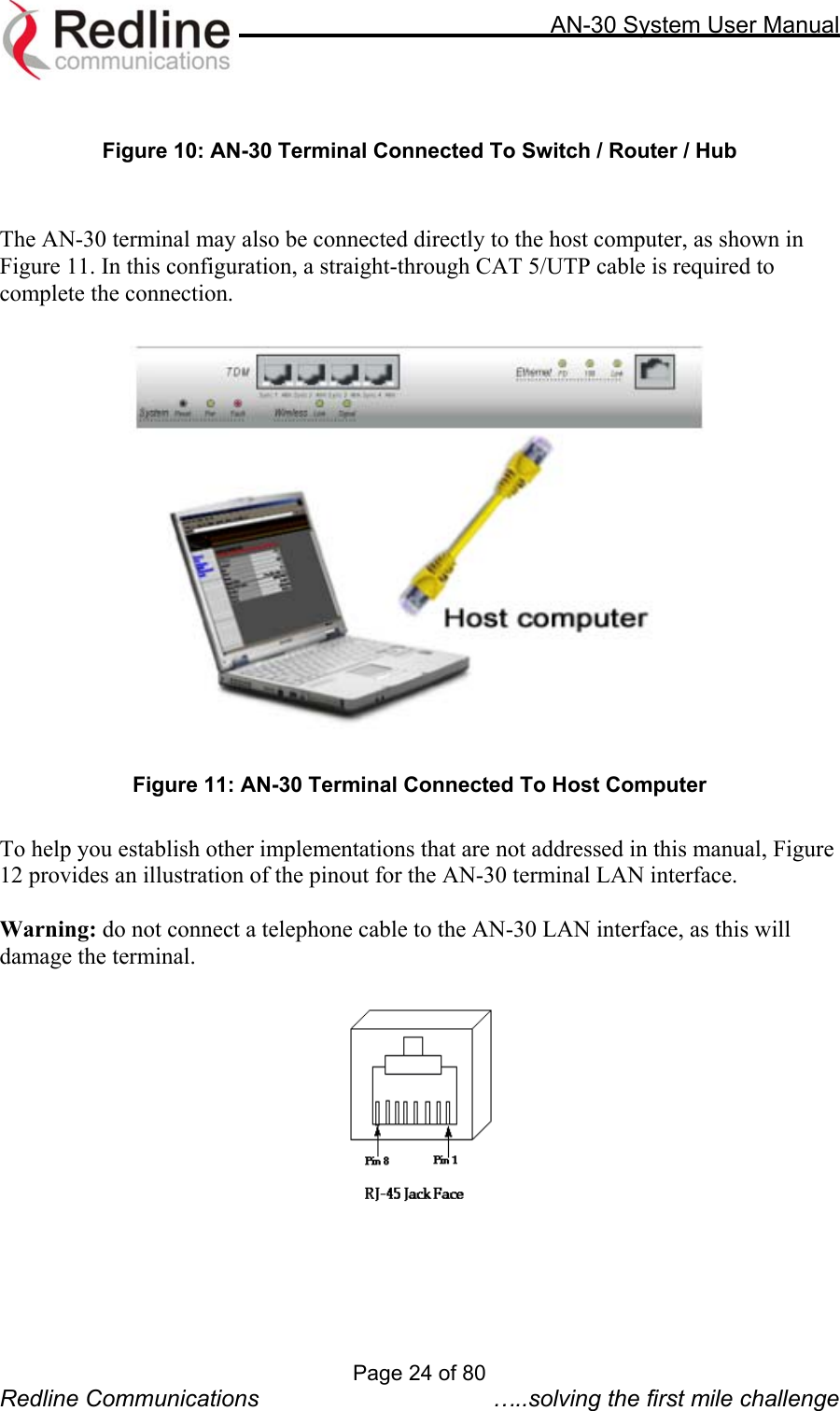
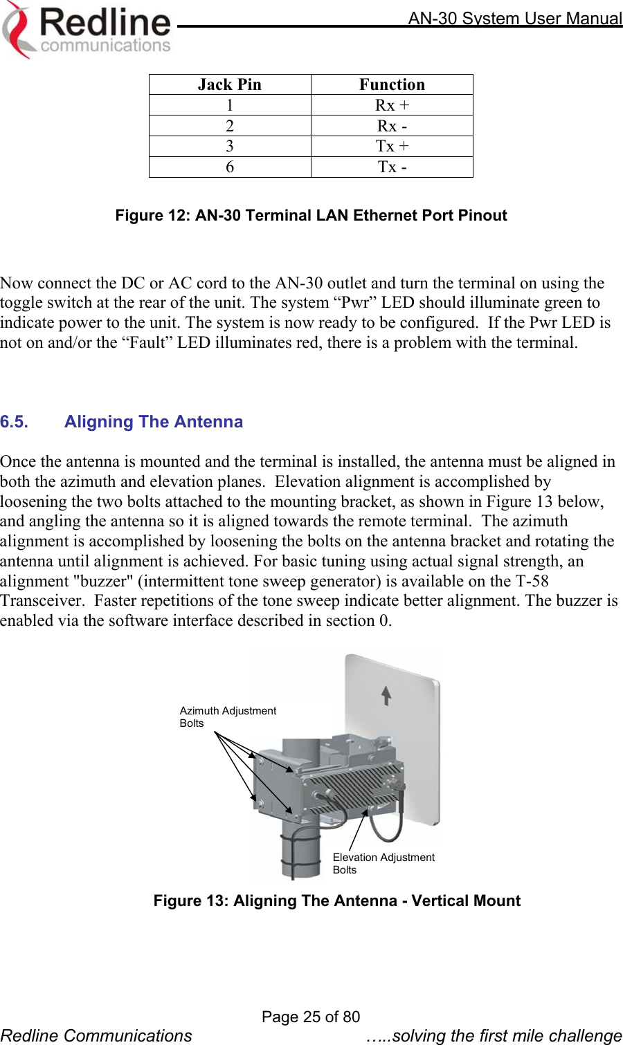
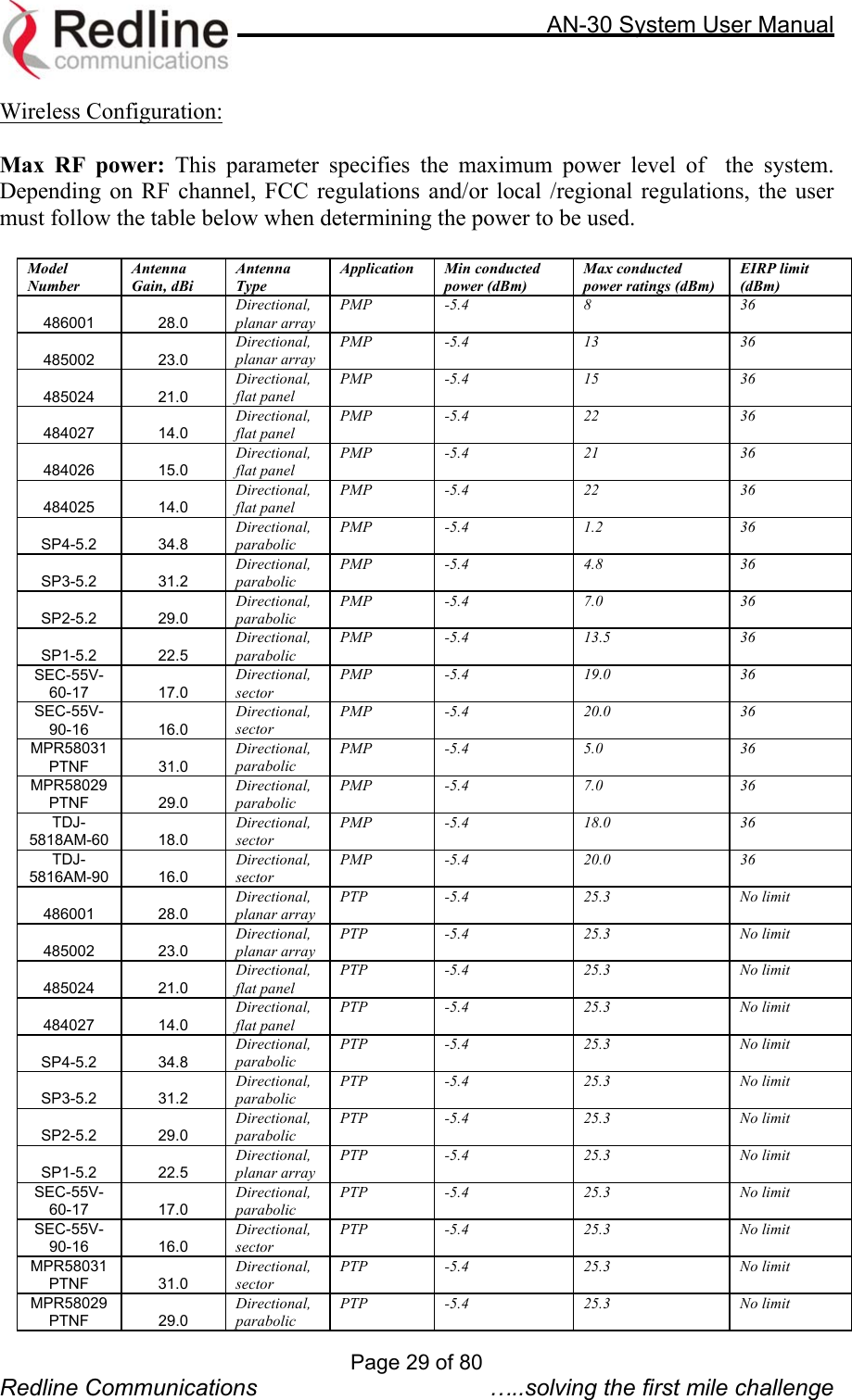
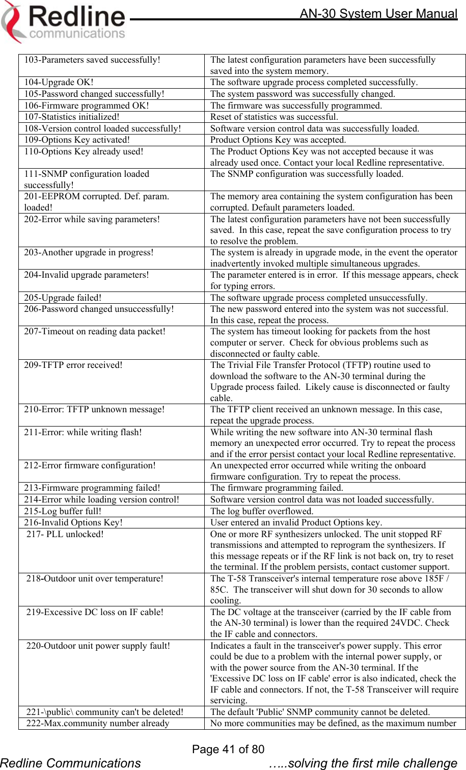
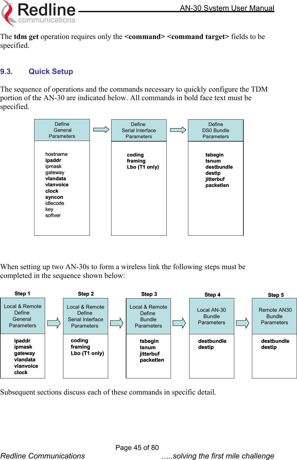
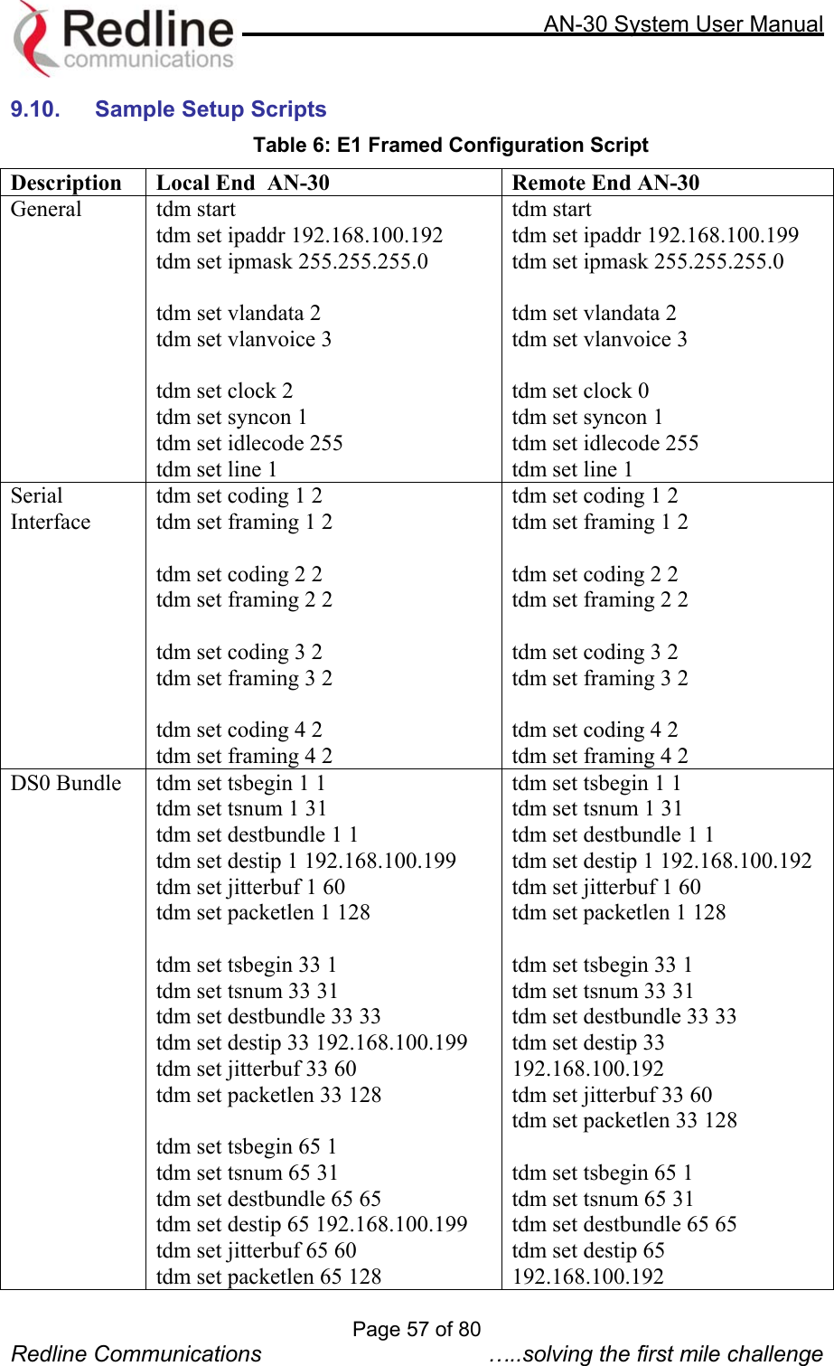
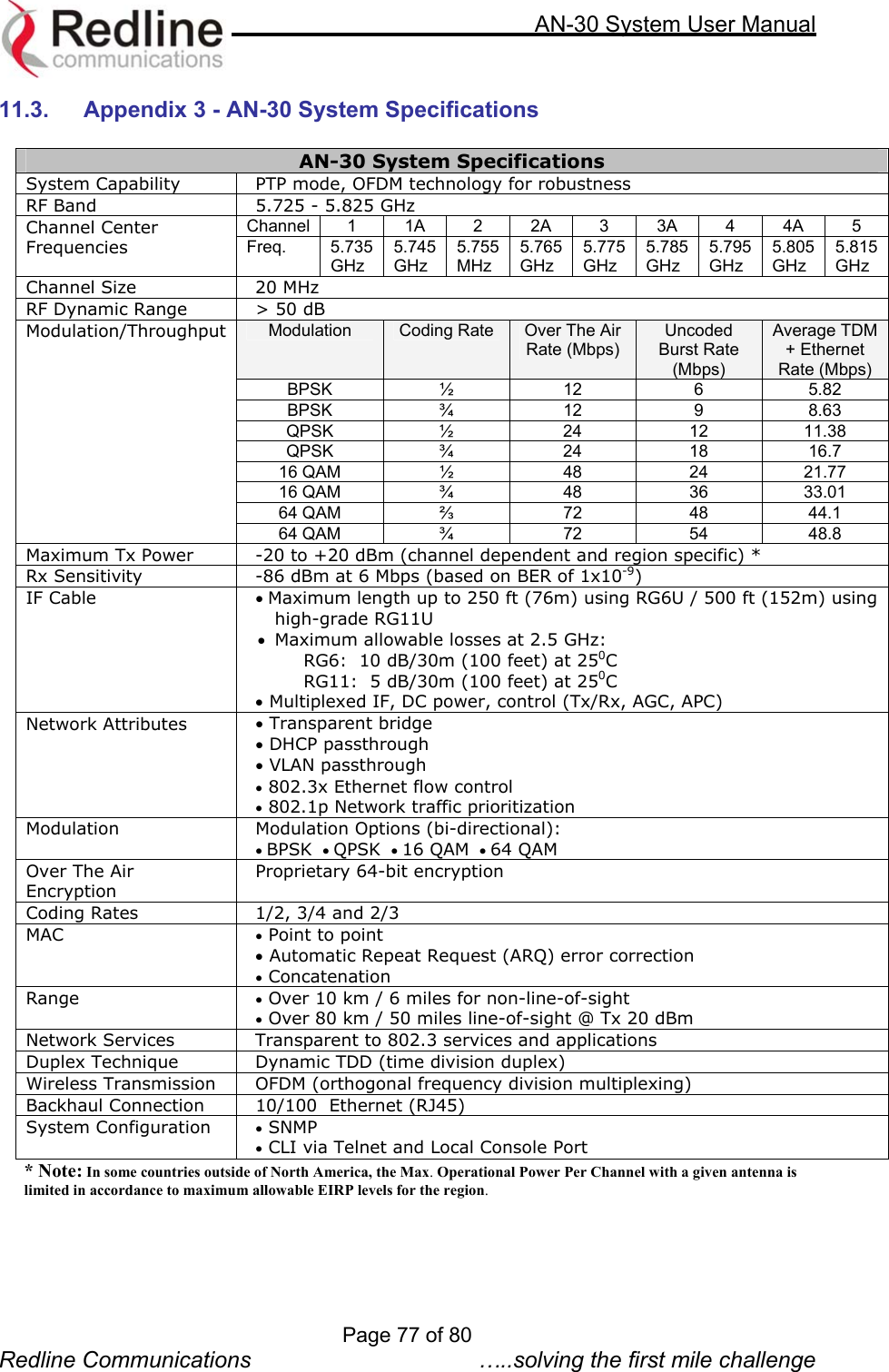
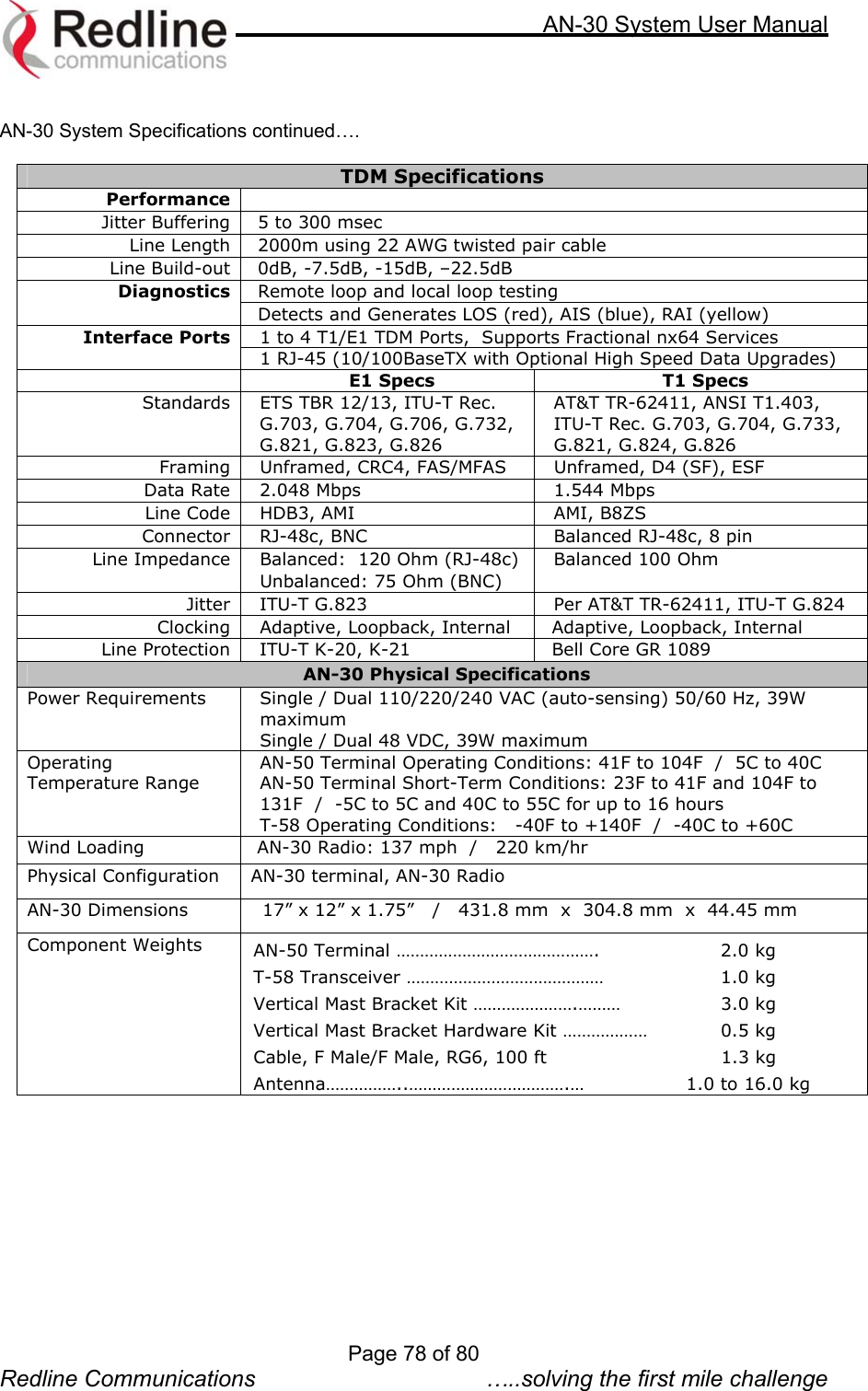
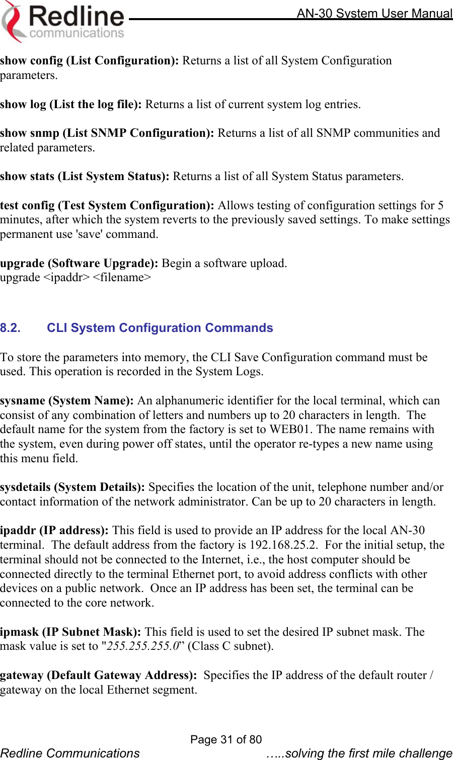
![AN-30 System User Manual TDJ-5818AM-60 18.0 Directional, parabolic PTP -5.4 25.3 No limit TDJ-5816AM-90 16.0 Directional, sector PTP -5.4 25.3 No limit AANN--3300 CCLLII ((CCoommmmaanndd LLiinnee IInntteerrffaaccee)) ffoorr WWiirreelleessss aanndd EEtthheerrnneett The CLI (Command Line Interface) System Configuration commands provide a simple to use User Interface for the operator to input a complete set of system parameters for the Ethernet, TDM card and Wireless components of the AN-30 terminal. The CLI command format for Telnet and the RS-232 port is as follow: <command> [parameter1] [parameter2] [parameter3] 8.1. CLI General Commands chgver (Change Software Version): Swaps the operating and secondary software versions get (Get parameter value): Get <parameter name> displays the value for a status parameter. For configuration parameters, use Set command. login: Allows login under a different username and password logout: Disconnects user from the terminal. passwd (Change Password): passwd <username> <newpassword> Change password for user. reboot: Reboot <time in seconds> Reboots the terminal. resetstats (Reset Statistics): Resets all statistics save config (Save Configuration): Permanently saves system configuration settings. This command is required to activate all Configuration settings set previously save snmp (Save SNMP Configuration): Permanently saves SNMP configuration settings. This command is required to activate all SNMP settings set previously. set (Set parameter value): Set one configuration parameter: <parameter name> [<value>]. Without <value>, ‘set’ returns the actual value for configuration parameters. For status parameters, use the Get command. Page 30 of 80 Redline Communications …..solving the first mile challenge](https://usermanual.wiki/Redline-Communications/AN30/User-Guide-353511-Page-30.png)
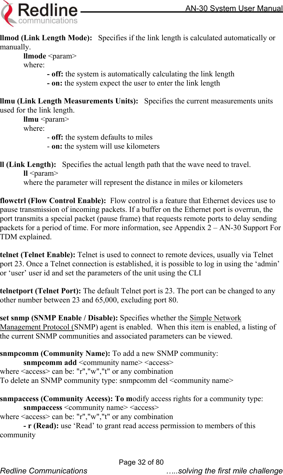
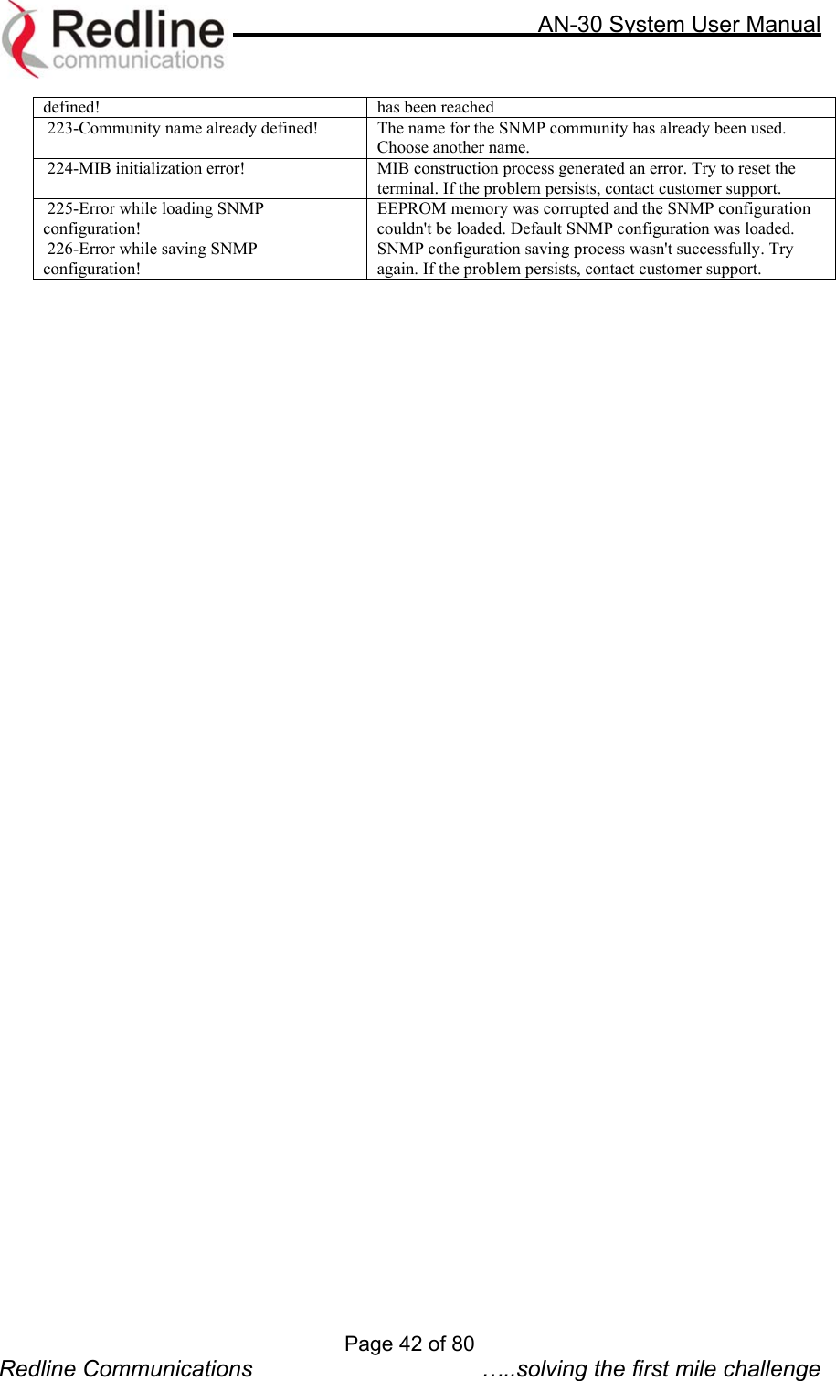
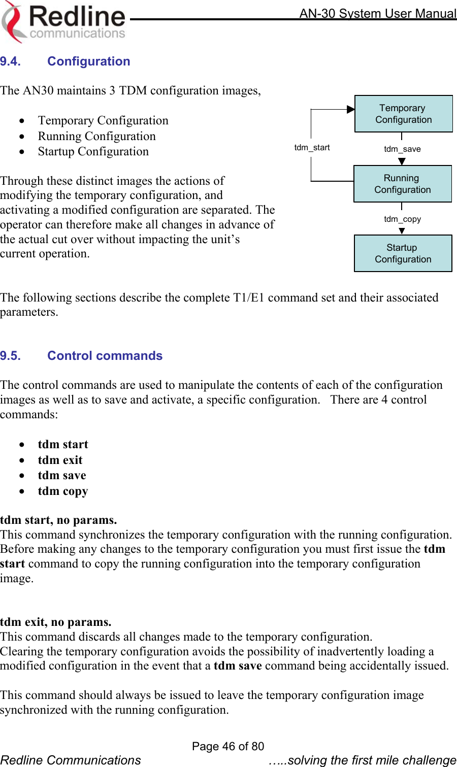
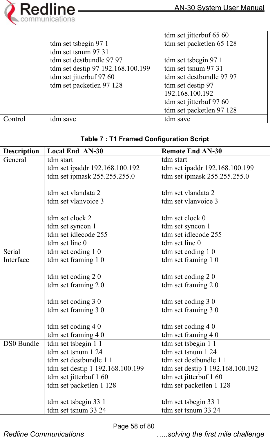
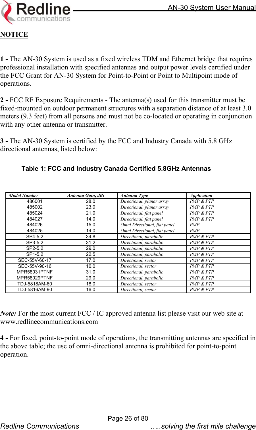
![AN-30 System User Manual 64QAM ¾ (54 Mb/s) 64QAM 2/3 (48 Mb/s) 16QAM ¾(36 Mb/s) 16QAM ½(24 Mb/s) QPSK ¾ (18 Mb/s) QPSK ½ (12 Mb/s) BPSK ¾ (9 Mb/s) BPSK ½ (6 Mb/s) Max Tx Power 14 15 19 20 20 20 20 20 adaptmod (Adaptive Modulation): checking this box sets the system to operate in adaptive modulation mode. It is not recommended to keep the AN-30 in this mode as the system will automatically change the modulation schemes thus errors can be introduced to the TDM traffic. For systems that have upgraded with a high-speed data option, it is recommended that the user set the modulation up to two levels below the maximum achievable on the link. The user can define the desired modulation scheme by setting the Uncoded Burst Rate parameter (see next item). If the current Uncoded Burst Rate meets or exceeds this rate, the Wireless Signal LED on the front panel lights solid green. If packet errors exceed one in one million, the system will automatically step down the modulation scheme to maintain the link. The Wireless Signal LED will flash green if the current Uncoded Burst Rate is lower than the configured Uncoded Burst Rate. If errors continue when the system reaches the lowest order modulation scheme, the Signal and Link LEDs will turn off to indicate a failed RF link. The dynamic modulation mode can be disabled by un-checking the Adaptive Modulation checkbox. In this manual mode, the user is required to set the Uncoded Burst Rate and the Modulation Reduction Level (see below). To operate in manual mode, first sample the link with Adaptive Modulation enabled, then switch to manual mode setting the modulation scheme up to 2 levels lower than that achieved using adaptive modulation. *Note: In some countries outside of North America, the Maximum Operational Power Per Channel with a given antenna is limited in accordance to maximum allowable EIRP levels for the region ubrate (Uncoded Burst Rate [Mb/s]): Defines the desired Uncoded Burst Rate for the link. Obtaining a 64 QAM license key (see section 8.6) raises the available Uncoded Burst Rate from the default 36 Mbps to 54 Mbps. modreduct (Modulation Reduction Level): applies when Adaptive Modulation is disabled. Specifies how many levels the system must drop in modulation during re-transmission of erroneous wireless packets. The level can be set from 0-7, with 2 being the recommended value. master (Master Mode): Sets the AN-30 system to serve as the master system, while the other AN-30 assumes a slave role. There are no consequences related to setting either unit to serve as the master or slave. One and only one unit must be set as the master. chgver (Software Version): Specifies the current version of the system software. Note that software can be remotely downloaded into the AN-30 terminal. The system includes sufficient memory to hold two independent software loads. The operator can specify which software load is used in the system. See section 8.4 for additional details. Page 34 of 80 Redline Communications …..solving the first mile challenge](https://usermanual.wiki/Redline-Communications/AN30/User-Guide-353511-Page-34.png)
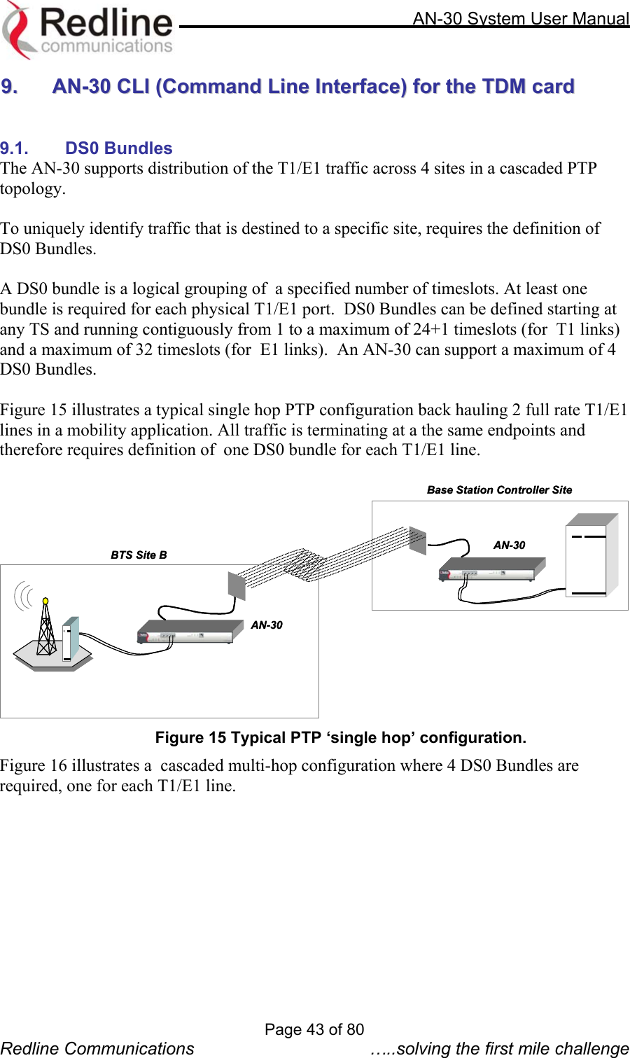
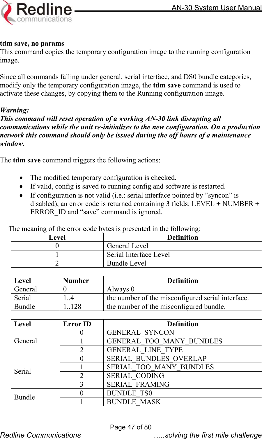
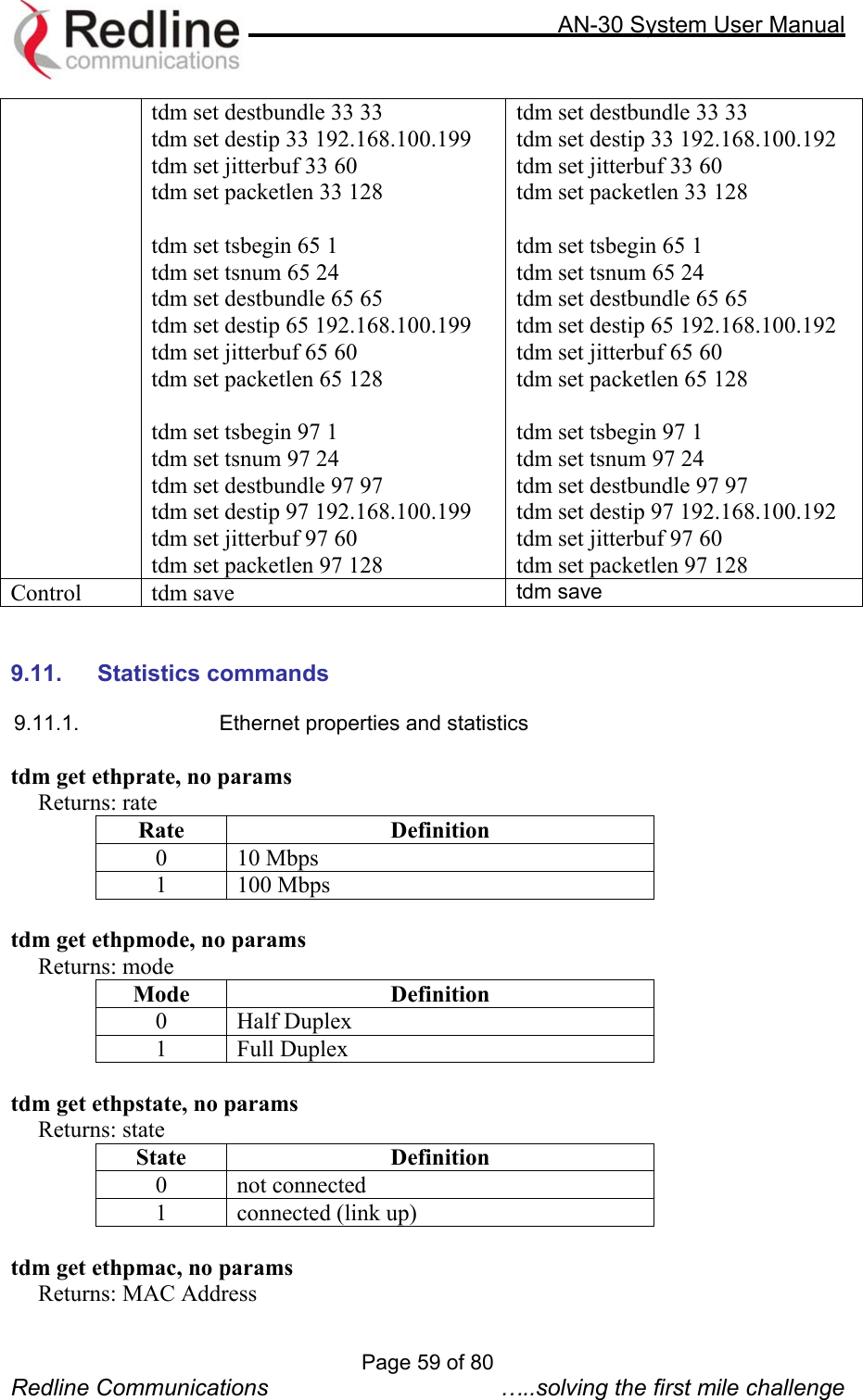
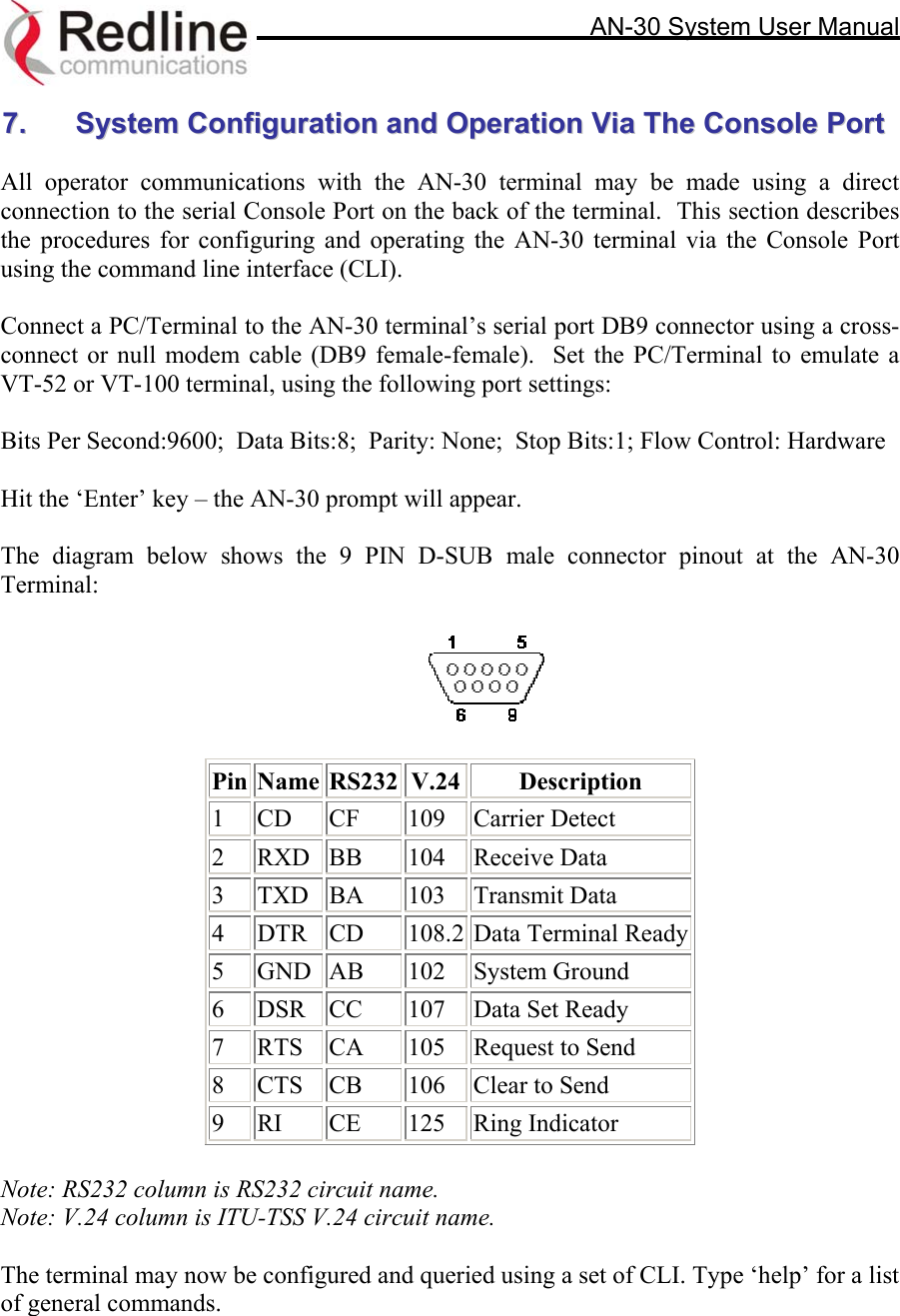
![AN-30 System User Manual encrypt (Encryption Enable): Specifies whether over-the-air encryption is enabled. Note that if encryption is enabled, it must be enabled on both the local and remote units, otherwise no Ethernet packets can be transferred. encryptkey (Encryption Key): Enter the MAC address of the remote terminal to enable over-the-air data encryption. Note, if encryption is enabled and the MAC address is not properly entered, no Ethernet packets can be transferred. buzzer (Alignment Buzzer Enable): Enables the antenna alignment tone sweep generator located in the T-58 Transceiver for fine tuning using actual signal strength. Faster repetitions of the tone sweep indicate better alignment. radio (Radio Enable): Specifies whether radio transmission is enabled. save config (Save configuration): Saves the currently entered parameters. test config (Test Configuration): Allows testing of the current settings for five minutes, after which the system reverts to the previously saved settings. To make settings permanent, click 'Save’. reboot (System Reset): Resets all statistics and reboots the terminal. 8.3. CLI General Status Information Commands The following is a brief description of each field of the CLI General Status Information sysname (System Name): Identifies the local terminal. The factory default name for the system is “WEB01”. sysdetails (System Details): Specifies the location, telephone number and/or contact information. ubrate (Uncoded Burst Rate [Mb/s]): Indicates the current uncoded burst rate of the system. With adaptive modulation, this data rate may change over time, depending on the prevailing propagation conditions. master (Master Mode): Indicates if the system is serving as the master or slave. swver (Software Version): Specifies the software version in use. starttime (Time Since System Start): Specifies the time [dd/hh/mm/ss] since the system started. Page 35 of 80 Redline Communications …..solving the first mile challenge](https://usermanual.wiki/Redline-Communications/AN30/User-Guide-353511-Page-35.png)
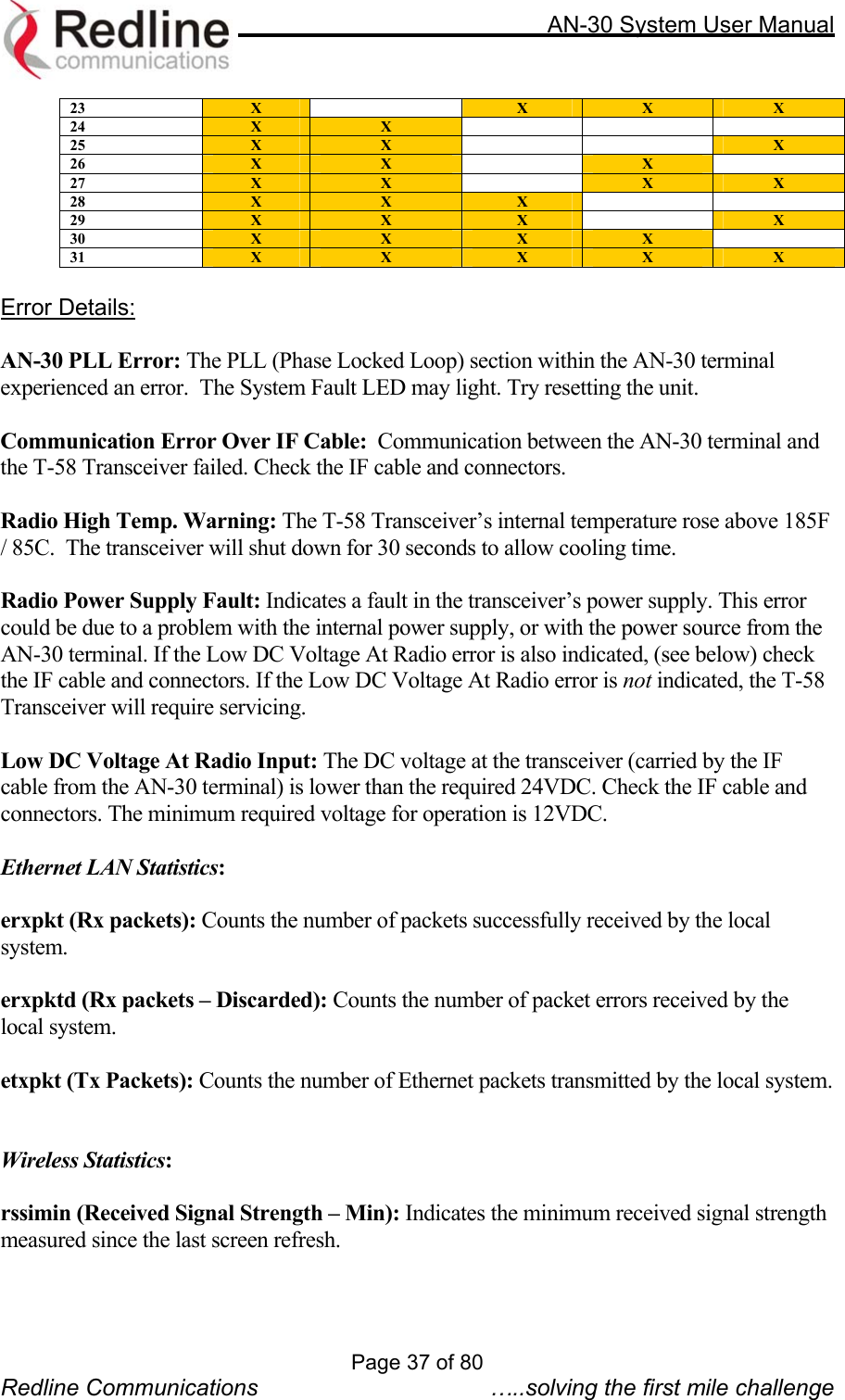
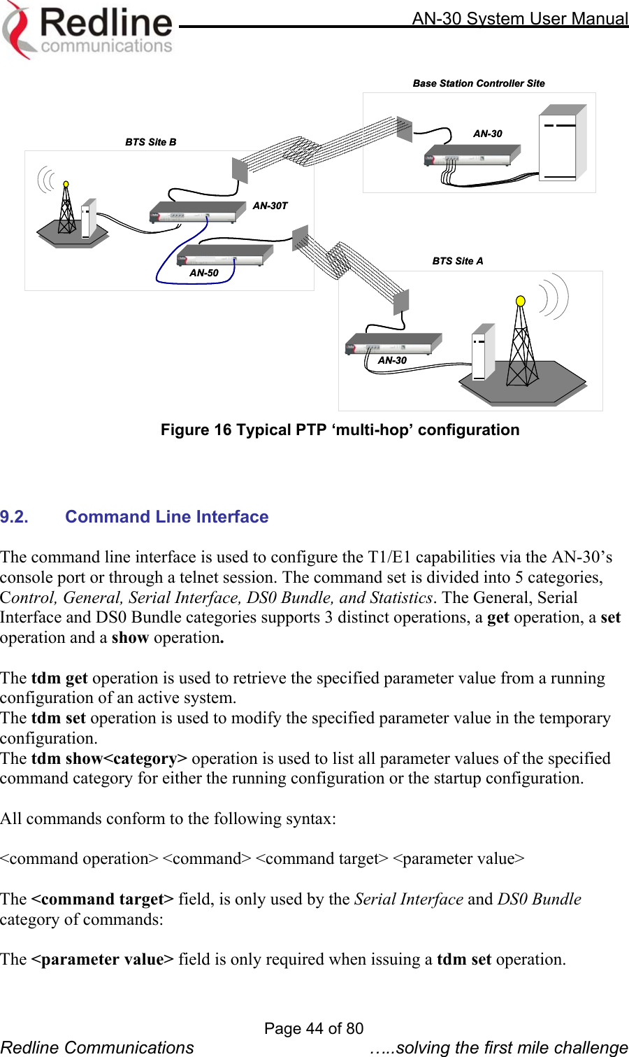
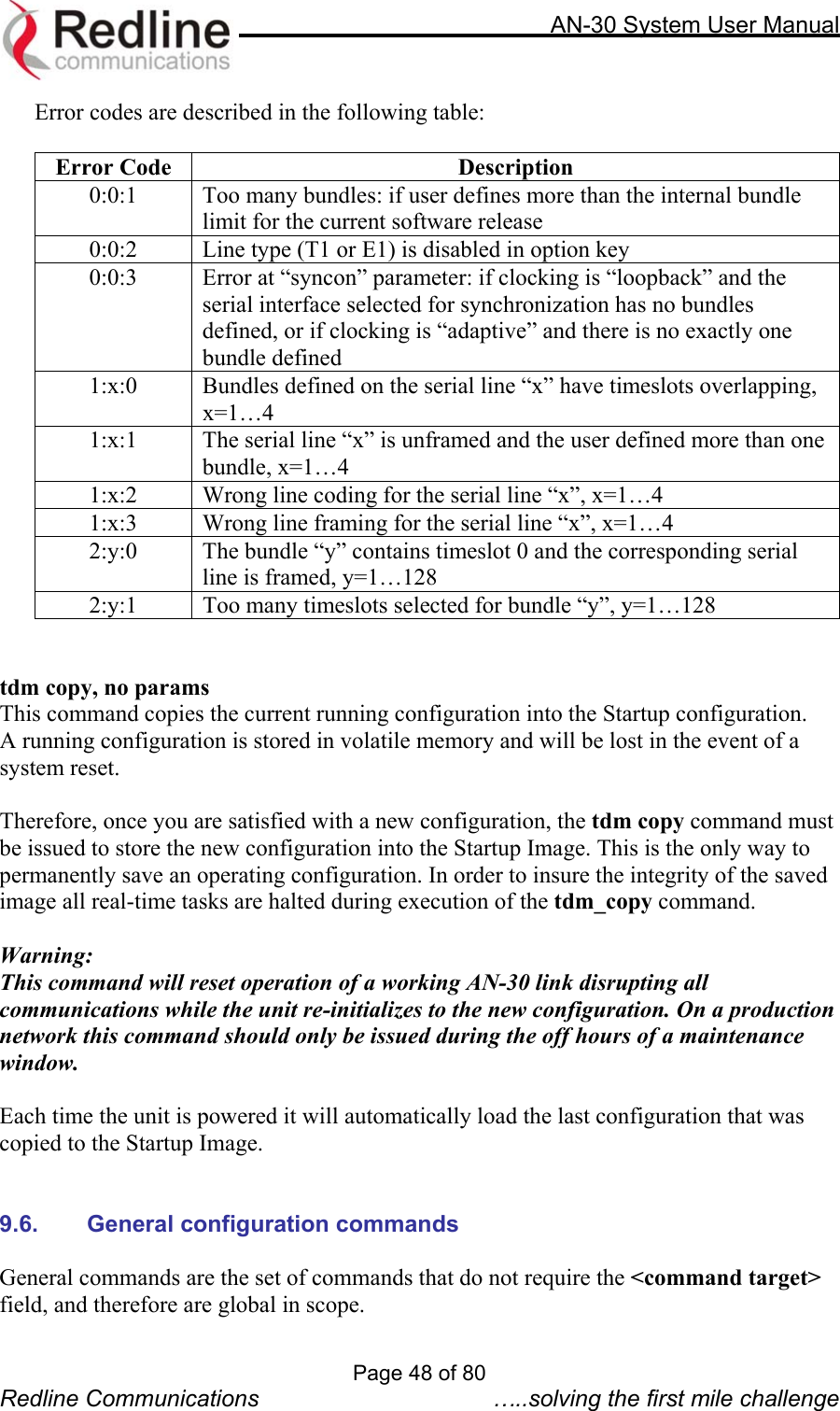
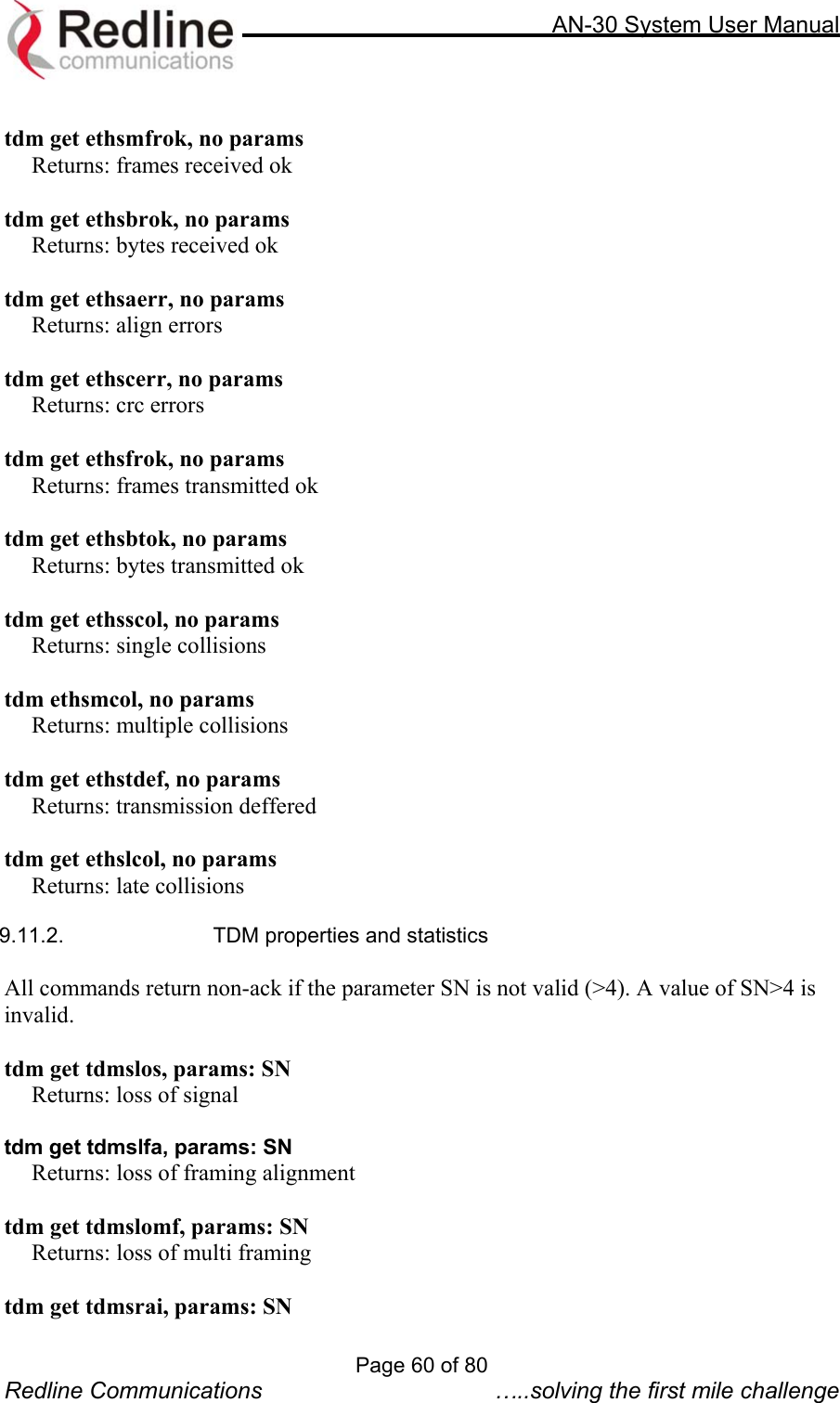
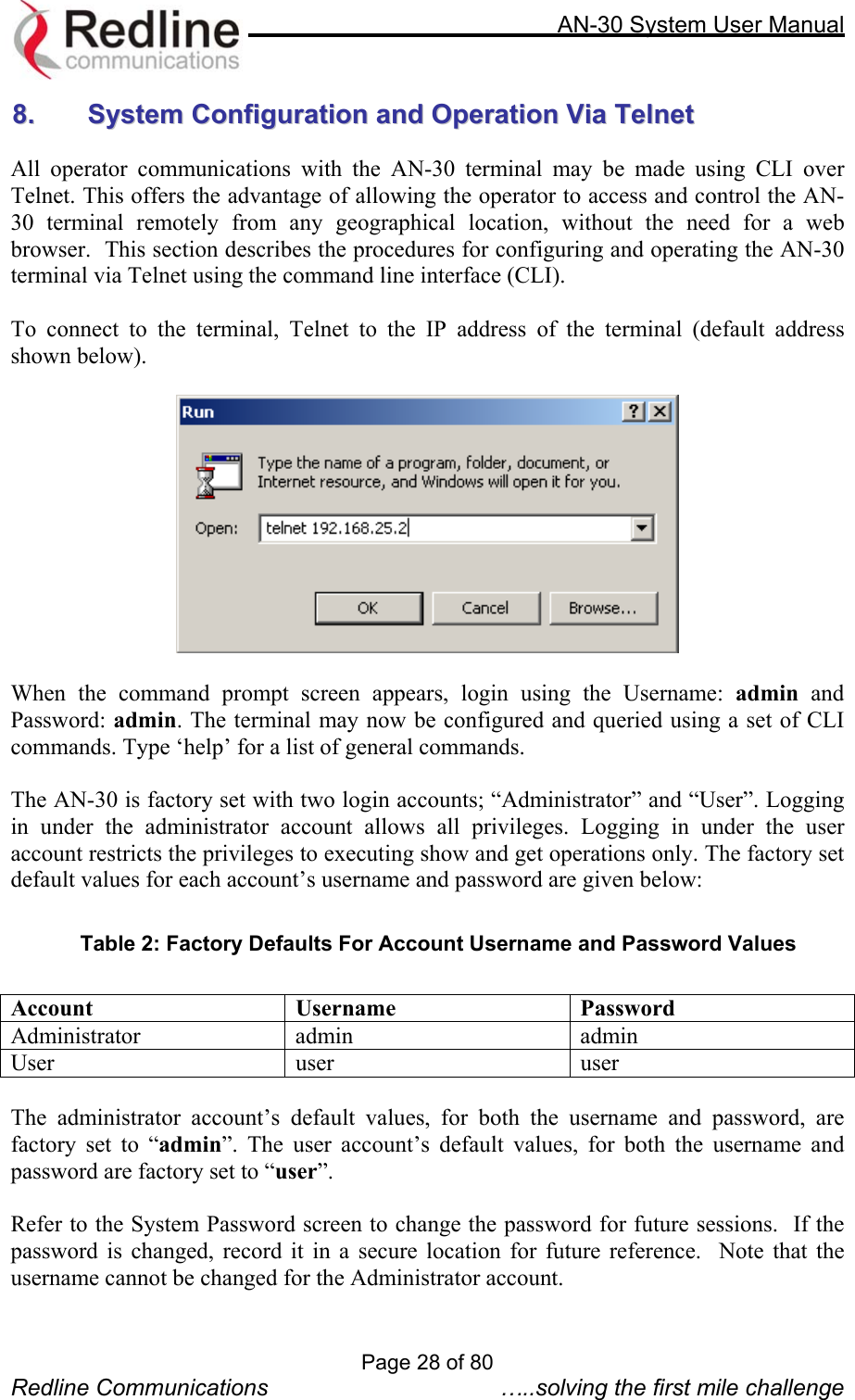
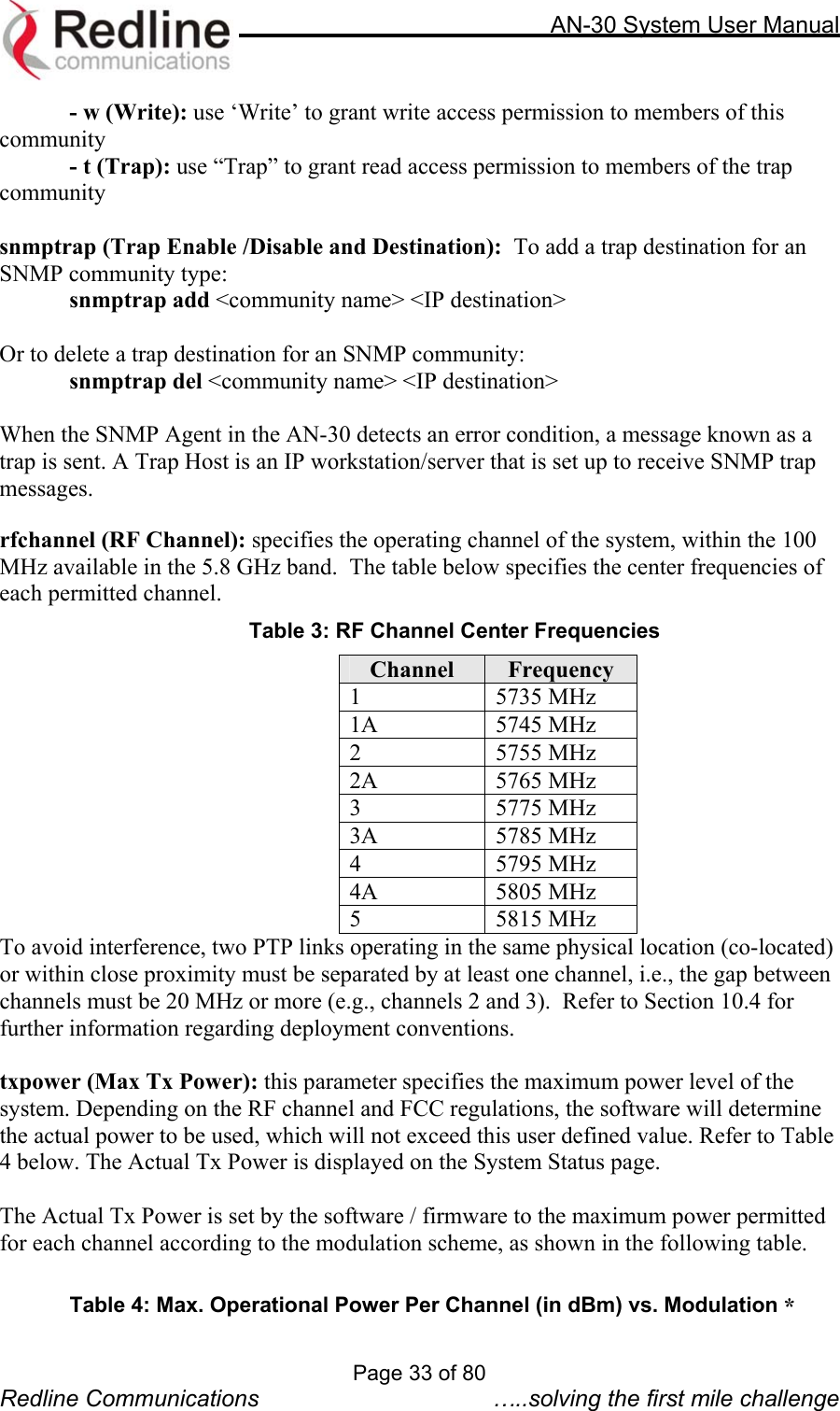
![AN-30 System User Manual macaddr (Ethernet MAC Address): Specifies the Ethernet MAC address used by the local terminal. ipaddr (IP Address): Specifies the IP address used by the local terminal. ipmask (IP Subnet Mask): Specifies the IP Subnet Mask used by the local terminal. gateway (Default Gateway Address): Specifies the IP address of the default router / gateway on the local Ethernet segment. ll (Link Length): Actual length of the path the wave travels rflink (RF Link Established): "Yes" indicates the RF link with the remote terminal is established. "No" indicates there is no RF link to the remote terminal. This indicator is correlated to the Wireless Link LED. rffreq (RF Channel Frequency): Specifies the center frequency of the channel in use. Tx Power: Specifies the actual current transmit power level. cableattn (Cable Attenuation): Indicates the attenuation of the signal over the IF cable. rfstatus (RF Status [Error Code]): An error code from 0-31 indicating the condition of the RF components within the AN-30 terminal and T-58 Transceiver. See the RF Status Error Code table below for details. Table 5: RF Status Error Codes Error Code AN-30 Terminal PLL Error Communication Error Over IF Cable Radio High Temp. Warning Radio Power Supply Fault Low DC Voltage At Radio Input 0 - NO ERRORS 1 X 2 X 3 X X 4 X 5 X X 6 X X 7 X X X 8 X 9 X X 10 X X 11 X X X 12 X X 13 X X X 14 X X X 15 X X X X 16 X 17 X X 18 X X 19 X X X 20 X X 21 X X X 22 X X X Page 36 of 80 Redline Communications …..solving the first mile challenge](https://usermanual.wiki/Redline-Communications/AN30/User-Guide-353511-Page-36.png)