Redline Communications AN30 AN30 SYSTEM User Manual
Redline Communications Inc. AN30 SYSTEM
users manual
AN-30 System User Manual
AN-30 System User Manual
AN-30 System
User Manual
Manual 70-00019-00 Rev. 3

AN-30 System User Manual
Redline Communications
AN-30 System User Manual
Copyright Information
This document may not in whole or in part be copied, reproduced, or reduced to any
medium without prior consent, in writing, from Redline Communications.
Disclaimer
This manual was designed to help you install, use and troubleshoot the Redline AN-30
Broadband Fixed Wireless (BFW) system. Every effort has been made to ensure the
accuracy of the material provided herein; however, Redline assumes no responsibility
regarding the use of the material. Additionally, Redline makes no representations or
warranties, either expressed or implied, regarding the contents of this product. Redline
Communications shall not be liable for any misuse regarding this product.
Page 2 of 80
Redline Communications …..solving the first mile challenge

AN-30 System User Manual
FCC & IC Information
1 - This equipment has been tested and found to comply with the limits for a Class A
digital device, pursuant to Part 15 of the FCC Rules. These limits are designed to provide
reasonable protection against harmful interference when the equipment is operated in a
commercial environment. This equipment generates, uses, and can radiate radio
frequency energy and, if not installed and used in accordance with the instruction manual,
may cause harmful interference to radio communications. Operation of this equipment in
a residential area is likely to cause harmful interference in which case the user will be
required to correct the interference at his/her own expense.
2 - A Class A digital device is marketed for use in a commercial, industrial or business
environment, exclusive of a device which is marketed for use by the general public or is
intended to be used in the home.
3 - Intentional or unintentional changes or modifications not expressly approved by the
party responsible for compliance must not be made. Any such modifications could void
the user’s authority to operate the equipment and will void the manufacturer’s warranty.
Contact Information
Redline Communications Inc.
302 Town Centre Blvd.,
Suite 101
Markham, ON
Canada L3R 0E8
Web site: http://www.redlinecommunications.com
Sales Inquiries:
North American – nainfo@redlinecommunications.com
International – intlinfo@redlinecommunications.com
Toll-free sales line – 1-866-633-6669
Support:
Email – support@redlinecommunications.com
Toll-free support line - 1-866-999-3537
Product Registration / Product Options:
http://www.redlinecommunications.com
Click on ‘Support’ User ID: Register Password: Redline
Comments or suggestions concerning this manual may be e-mailed to the support team.
Page 3 of 80
Redline Communications …..solving the first mile challenge

AN-30 System User Manual
TABLE OF CONTENTS
1. Getting Started .......................................................................................................... 8
1.1. How To Use This Manual ..................................................................................8
1.2. AN-30 System Overview ................................................................................... 8
1.3. TDM over Wireless Theory of Operation...........................................................9
2. Important Safety Information...................................................................................10
3. Important Service Information ................................................................................. 12
4. Unpacking the AN-30 System ................................................................................. 13
5. The AN-30 Terminal at a Glance............................................................................. 14
5.1. The AN-30 System’s T-58 Transceiver / Antenna at a Glance ....................... 18
6. AN-30 System Installation.......................................................................................19
6.1. General Site Survey ........................................................................................ 20
6.2. Installing The Antenna..................................................................................... 21
6.3. Running The IF Cable .....................................................................................22
6.4. Installing The Terminal ....................................................................................23
6.5. Aligning The Antenna ...................................................................................... 25
7. System Configuration and Operation Via The Console Port ................................... 27
8. System Configuration and Operation Via Telnet.....................................................28
9. AN-30 CLI (Command Line Interface) for Wireless and Ethernet ........................... 30
9.1. CLI General Commands.................................................................................. 30
9.2. CLI System Configuration Commands ............................................................ 31
9.3. CLI General Status Information Commands....................................................35
9.4. Upload Software.............................................................................................. 38
9.5. System Password............................................................................................ 39
9.6. AN-30 Options................................................................................................. 39
9.7. System Logs.................................................................................................... 40
10. AN-30 CLI (Command Line Interface) for the TDM card.....................................43
10.1. DS0 Bundles................................................................................................ 43
10.2. Command Line Interface ............................................................................. 44
10.3. Quick Setup................................................................................................. 45
10.4. Configuration ............................................................................................... 46
10.5. Control commands ...................................................................................... 46
10.6. General configuration commands................................................................ 48
10.7. Serial interface configuration commands .................................................... 52
10.8. DS0 Bundle configuration commands ......................................................... 53
10.9. ............................................................................................................................ 56
10.10. Sample Setup Scripts..................................................................................57
10.11. Statistics commands.................................................................................... 59
10.11.1. Ethernet properties and statistics ........................................................ 59
10.11.2. TDM properties and statistics ..............................................................60
11. Broadband Fixed Wireless Primer....................................................................... 62
11.1. Who Can Benefit From The AN-30 System?............................................... 62
11.2. The AN-30 Advantage ................................................................................. 64
11.3. Wireless Facts............................................................................................. 66
11.3.1. The Link Budget Tool .............................................................................. 66
11.4. Deployment Scenarios ................................................................................ 72
11.4.1. Co-located Deployments .........................................................................72
11.4.2. Adjacent Area Deployments .................................................................... 72
12. Appendix ............................................................................................................. 74
Page 4 of 80
Redline Communications …..solving the first mile challenge

AN-30 System User Manual
12.1. Appendix 1 - Glossary Of Terms ................................................................. 74
12.2. Appendix 2 – AN-30 Support For TDM explained ....................................... 76
12.3. Appendix 3 - AN-30 System Specifications ................................................. 77
Page 5 of 80
Redline Communications …..solving the first mile challenge

AN-30 System User Manual
LIST OF TABLES
Table 1: FCC and Industry Canada Certified 5.8GHz Antennas..................................... 26
Table 2: Factory Defaults For Account Username and Password Values ...................... 28
Table 3: RF Channel Center Frequencies ...................................................................... 33
Table 4: Max. Operational Power Per Channel (in dBm) vs. Modulation........................ 33
Table 5: RF Status Error Codes...................................................................................... 36
Table 6: E1 Framed Configuration Script........................................................................57
Table 7 : T1 Framed Configuration Script ....................................................................... 58
Table 8: Modulation Scheme vs. Data Rate................................................................... 67
Table 9: Availability Versus Outage Time ....................................................................... 69
Table 10: Radar Horizon Ranges For Different Terminal Heights (H1 and H2) ............... 71
Page 6 of 80
Redline Communications …..solving the first mile challenge

AN-30 System User Manual
LIST OF FIGURES
Figure 1: The AN-30 System Out Of The Box................................................................. 13
Figure 2: Front Panel – System ...................................................................................... 14
Figure 3: Front Panel - Wireless ..................................................................................... 15
Figure 4: Front Panel – Ethernet..................................................................................... 15
Figure 5: LAN Interface................................................................................................... 16
Figure 6: AN-30 Radio With Vertical Mount ....................................................................18
Figure 7: AN-30 System Installation................................................................................ 19
Figure 8: Radio Deployment Options .............................................................................. 21
Figure 9: IF Cable .............................................................................................................. 22
Figure 10: AN-30 Terminal Connected To Switch / Router / Hub ................................... 24
Figure 11: AN-30 Terminal Connected To Host Computer ............................................. 24
Figure 12: AN-30 Terminal LAN Ethernet Port Pinout .................................................... 25
Figure 13: Aligning The Antenna - Vertical Mount .......................................................... 25
Figure 14: System Logs Screen...................................................................................... 40
Figure 15 Typical PTP ‘single hop’ configuration............................................................43
Figure 16 Typical PTP ‘multi-hop’ configuration.............................................................. 44
Figure 17: Wireless Extension for Carriers ..................................................................... 62
Figure 18: Wireless Solution For ISPs ............................................................................ 63
Figure 19: Wireless Solution For Enterprise ................................................................... 64
Figure 20: Fresnel Zone Obstruction .............................................................................. 68
Figure 21: Fresnel Zone Radius Calculation................................................................... 68
Figure 22: Link Budget For 64 QAM ¾ Code Rate ........................................................ 70
Figure 23: Fade Margin Graphs For LOS, OLOS and NLOS.......................................... 71
Figure 24: Adjacent Channel Interference. ..................................................................... 72
Figure 25: Deployment Scenarios................................................................................... 73
Page 7 of 80
Redline Communications …..solving the first mile challenge

AN-30 System User Manual
1
1.
.
G
Ge
et
tt
ti
in
ng
g
S
St
ta
ar
rt
te
ed
d
1.1. How To Use This Manual
This User Manual is designed to get you started using the Redline Communications
Access Node-30 (AN-30) Broadband Fixed Wireless (BFW) system by guiding you
through the step-by-step process of setting up the system for the first time.
To that end, the following principal steps will need to be followed in the order presented:
Review the safety and service information (Sections 2 and 3 of this manual)
Unpack the AN-30 system (Section 4)
Install the outdoor radio (transceiver plus antenna) (Section 6)
Install the indoor terminal (Section 6)
Configure the system via a host computer and (CLI) interface (Section 8)
Ensure the encryption key has been properly configured (see Section 0)
Install the 16/64 QAM license key to activate high speed Ethernet access (see Section 8.6
on page39)
This User Manual will also help with the following:
Understanding Fixed Wireless Systems
Referencing AN-30 System Specifications
Troubleshooting the System
1.2. AN-30 System Overview
The AN-30 is a wireless transport system providing simultaneous interfacing for legacy
TDM and data traffic. Its architecture makes it an ideal platform to facilitate the
migration from a TDM based telecom infrastructure to a fully packet based VoIP Next
generation network.
The AN-30 can simultaneously support the transport of up to four (4) full or two (2)
fractional rate T1/E1 lines along with high speed Ethernet access, available through
optional license keys.
The AN-30 system operates in the licensed exempt band of 5.8 GHz and includes
advanced technologies to address any potential inter-cell interference issues. The system
supports modulation schemes, including BPSK, QPSK, 16 and 64 QAM to maximize
data rate, and hence spectral efficiency. The system also features selective coding to
ensure maximum robustness, and hence error free performance in the presence of hostile
propagation conditions.

AN-30 System User Manual
The AN-30 can be equipped with a narrow beam antenna to provide high directivity for
long-range operations up to 30 miles (50 km) under line of sight (LOS) conditions, and
up to 6.2 miles (10 km) under non line of sight (NLOS) conditions.
The AN-30 system is a Class A digital device for use in a commercial, industrial or
business environment.
1.3. TDM over Wireless Theory of Operation
TDM transport is achieved through a form of circuit emulation, which has been
specifically optimized for wireless operation.
TDM traffic, digitized voice or chanelized data, is received by the AN-30 at the RJ48 /
BNC interfaces, interpreted and encapsulated within an Ethernet frame structure. The
Ethernet encapsulated traffic is then transported over the wireless link to a remote end
AN-30, where the TDM traffic is reconstructed by reversing the encapsulation process
and re-clocking the TDM traffic.
Variable delay is commonly associated with packet based networks and can be
introduced by the AN-30 during packet processing and transmision of simultaneous TDM
and data traffic streams. In order to insure proper timing of the reconstructed traffic, the
remote AN-30 employs a jitter buffer that is user defined between 5 and 300 msec. The
jitter buffer is used to compensate for any delay variation that may occur during transport
of the ethernet encapsulated traffic. For time sensitive applications, such as TDM voice,
the buffer is typically set below 10 msec, while more data centric applications would
employ a buffer that is closer to 300 msec to maximize packet efficiency.
Fractional nx64 services are also supported by allowing the user to specify which
timeslot chanels to transport over the wireless link. Timeslots can be set from 1 to 24 for
T1 and from 1 to 32 for E1.
The AN-30 supports IEEE 802.1p, 802.1Q and 802.3x. Using these standards for VLAN
tagging prioritization and flow control the AN-30 is able to maintain the necessary QoS
guarantees for TDM traffic while simultaneously transporting data applications using the
excess bandwidth.
Page 9 of 80
Redline Communications …..solving the first mile challenge

AN-30 System User Manual
2
2.
.
I
Im
mp
po
or
rt
ta
an
nt
t
S
Sa
af
fe
et
ty
y
I
In
nf
fo
or
rm
ma
at
ti
io
on
n
1 Read this User Manual and follow all operating and safety instructions.
2 Keep all product information for future reference.
3 This product is supplied with a grounding power plug. Do not defeat this
important safety feature.
4 The power requirements are indicated on the product-marking label. Do not
exceed the described limits.
5 Always replace the fuse with the correct type and current rating.
6 Position the power cord to avoid possible damage, and do not overload wall
outlets.
7 Do not place this product on or near a direct heat source, and avoid placing
objects on the terminal.
8 Do not operate this device near water or in a wet location.
9 Use only a damp cloth for cleaning. Do not use liquid or aerosol cleaners.
Disconnect the power before cleaning.
10 Protect the unit by disconnecting the power if it is not used for long periods of
time.
11 Locate the AN-30 terminal on a stable horizontal surface or mount it securely in a
19” Telco rack.
12 The T-58 Transceiver unit must not be located near power lines or other electrical
power circuits.
13 The T-58 Transceiver must be properly grounded to protect against power surges
and accumulated static electricity. It is the user’s responsibility to install this device in
accordance with Section 810 of the National Electrical Code, ANSI/NFPA No. 70-1984
or Section 54 of the Canadian Electrical Code. These codes describe correct installation
procedures for grounding of the transceiver unit, mast, lead-in wire and discharge unit,
location of discharge unit, size of grounding conductors and connection requirements for
grounding electrodes. It is recommended that the installation of the transceiver be
contracted to a professional installer.
Page 10 of 80
Redline Communications …..solving the first mile challenge

AN-30 System User Manual
The following symbols may be encountered during installation or troubleshooting. These
warning symbols mean danger. Bodily injury may result if you are not aware of the
safety hazards involved in working with electrical equipment and radio transmitters.
Familiarize yourself with standard safety practices before continuing.
Electro-Magnetic Radiation
High Voltage
Page 11 of 80
Redline Communications …..solving the first mile challenge

AN-30 System User Manual
3
3.
.
I
Im
mp
po
or
rt
ta
an
nt
t
S
Se
er
rv
vi
ic
ce
e
I
In
nf
fo
or
rm
ma
at
ti
io
on
n
1 Refer all repairs to qualified service personnel. Do not remove the covers or
modify any part of this device, as this will void the warranty.
2 Disconnect the power to this product and return it for service if the following
conditions apply:
a) The unit does not function after following the operating instructions outlined in
this manual.
b) Liquid has been spilled, a foreign object is inside or the AN-30 terminal has
been exposed to rain.
c) The product has been dropped or the housing is damaged.
3 Locate the serial number of the AN-30 Terminal, Antenna, and T-58 Transceiver
and record these on your registration card for future reference. Use the space below to
affix serial number stickers. Also record the MAC address, located on the back of the
AN-30 Terminal.
Product Information
AN-30 Terminal SN:________________ AN-30 Terminal MAC Address:_________________
T-58 Transceiver SN:_______________________ Model #: ___________________________
Antenna Model No.:__________________ Antenna SN:_______________________________
Serial Number Stickers
Page 12 of 80
Redline Communications …..solving the first mile challenge
AN-30 System User Manual
4
4.
.
U
Un
np
pa
ac
ck
ki
in
ng
g
t
th
he
e
A
AN
N-
-3
30
0
S
Sy
ys
st
te
em
m
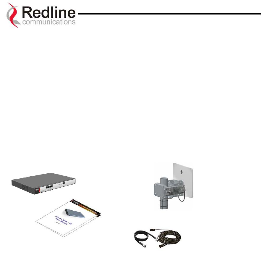
The AN-30 system comes packaged with the following major items (refer to Figure 1 for
a pictorial view):
• AN-30 terminal (indoor unit)
• AN-30 Radio (outdoor unit):
• T-58 Transceiver
• Antenna
• Antenna Mounting Bracket
• Power Cord and outdoor IF Cable (100 ft. / 30.5 m)
• User Manual
AN-30 Terminal AN-30 Radio
Power/IF
Cables
V
ertical
Mount
User Manual
Figure 1: The AN-30 System Out Of The Box
A complete list of items included in the system is available on the packing list included
with the system.
Page 13 of 80
Redline Communications …..solving the first mile challenge
AN-30 System User Manual
5
5.
.
T
Th
he
e
A
AN
N-
-3
30
0
T
Te
er
rm
mi
in
na
al
l
a
at
t
a
a
G
Gl
la
an
nc
ce
e
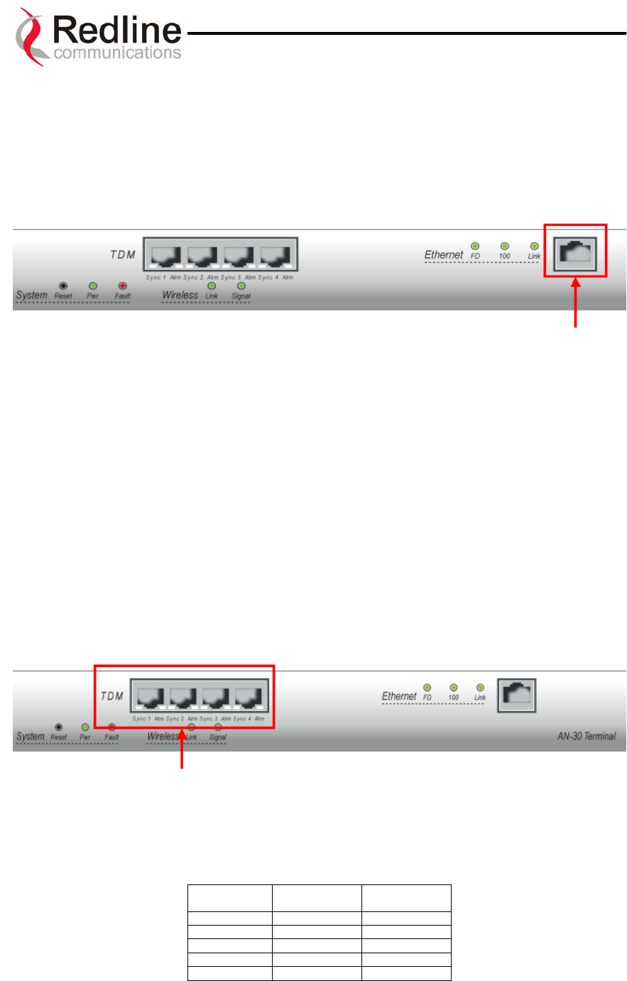
The front panel of the AN-30 terminal includes an RJ45 Ethernet interface, four (4) RJ48
/ BNC E1/T1 interfaces and four (4) grouped status indicators; System, Wireless, TDM
and Ethernet. The rear of the terminal includes the power cord connector and an F-Type
female connector for the IF cable.
At power up, an LED power-up sequence occurs as follows:
All three Ethernet LEDs light for one second, then individual Ethernet LEDs blink twice
in the following order: 100, FD, Link. The Fault LED lights for approximately four
seconds, then turns off. The two Wireless LEDs remain off for approximately five
seconds, then blink once and resume their normal state.
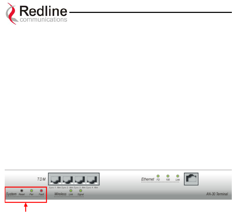
A) System Status Indicators
The System portion of the front panel features a recessed reset switch and two LEDs
(Pwr and Fault), as shown in the figure below.
Figure 2: Front Panel – System
Reset – The system can be manually hard reset by depressing the “Reset” button recessed
in the front panel. The reset button is used to reactivate the terminal in the event that it is
functioning improperly or is in a state of suspension.
Pwr – The “Pwr” LED lights solid green when the AC power is properly applied to the
terminal. In the event of internal power supply failure, if the cord is disconnected, or if
the fuse is blown, the “Pwr” light will not illuminate.
Fault – The “Fault” LED lights solid red when a serious fault is detected within the
system.
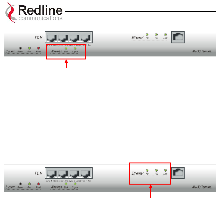
B) Wireless Status Indicators
The Wireless portion of the front panel features two LEDs; Link and Signal, as shown
below.
Page 14 of 80
Redline Communications …..solving the first mile challenge
AN-30 System User Manual
Figure 3: Front Panel - Wireless
Link – The “Link” LED lights solid green when the radio link to the remote terminal is
established. The LED will turn off if the link is lost.
Signal – The “Signal” LED lights solid green if the system is operating at the configured
Uncoded Burst Rate. See section on for a detailed description.
C) Ethernet Status Indicators
The Ethernet status portion of the front panel display consists of three LEDs; Link, 100,
FD, as shown below.
Figure 4: Front Panel – Ethernet
Link – The “Link” LED illuminates solid green when the Local Area Network (LAN)
connection is established, and there is no traffic. The Link LED will flash when the
Local Area Network (LAN) connection is established, and there is traffic.
100 – The “100” LED lights solid green when the Ethernet port is operating at 100 Mb/s.
The LED will not illuminate if the port is operating in 10 Mb/s mode. The Ethernet port
automatically selects the speed through auto-negotiation with either the host
computer/server or router/switch.
FD – The “FD” LED is used to indicate if the Ethernet link is in full duplex and half
duplex mode. It illuminates solid green for full duplex, and is set off to indicate half
duplex mode. On a shared Ethernet networks, collisions are also indicated through the
intermittent flashing of this LED. The system automatically selects the duplex mode
through auto-negotiation with the host computer or switch.
Page 15 of 80
Redline Communications …..solving the first mile challenge
AN-30 System User Manual
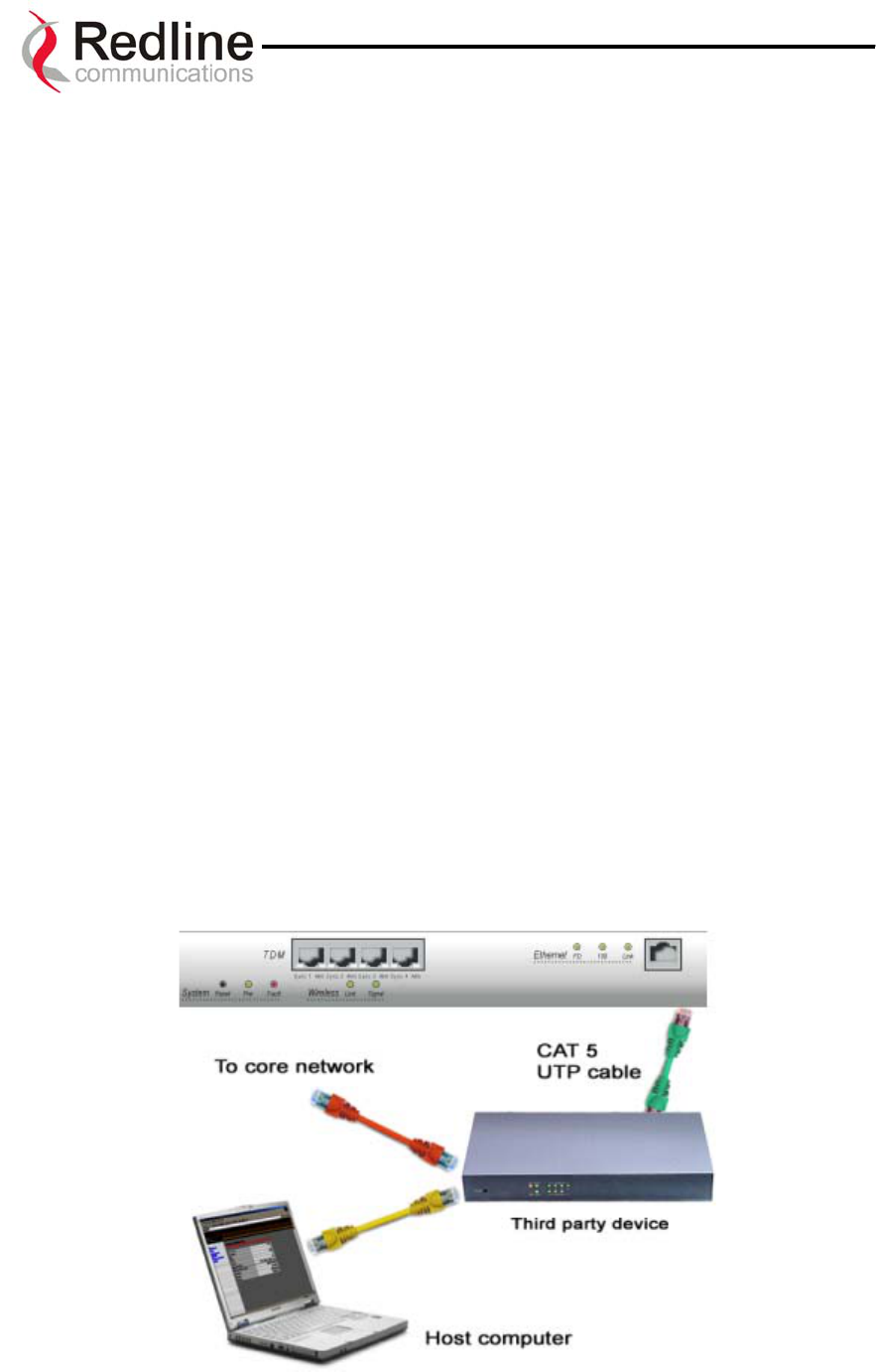
D) The LAN Interface
The LAN interface is a 10/100 BaseT Ethernet port, which is used to connect the AN-30
terminal to either the core network or to a host computer. A router or switch is often used
to complete the connection to the core network, as shown in the figure below. Note that
different cables are required for connection to a hub/switch/router or host computer.
Figure 5: LAN Interface
All AN-30 base systems come equipped with basic Ethernet access (limited at under 2
Mbps). This feature is provided solely for the purpose of enabling remote in-band
management. Optional license keys are available to activate access at higher speeds.
Warning
Exceeding the basic access rate of this port may impact the performance on the TDM
interfaces.
E) The TDM Interface
The TDM interface includes four RJ48 / BNC E1/T1 ports, which are used to connect the
AN-30 terminal to either a PBX or to another E1/T1 device. Note that different cables are
required for connection to a third-party E1/T1 device.
Figure 6: TDM Interface
Each serial interface port has two LED indicators Alarm and Sync. LED indications are
coded as follows for single alarm conditions
ALARM Alarm LED
(Amber)
Sync LED
(Green)
LOS On Off
LFA On Blink
AIS Off Off
RAI Flashes Off
No Alarm Off On
Page 16 of 80
Redline Communications …..solving the first mile challenge

AN-30 System User Manual
The LEDs are able to report multiple alarm conditions as shown in the following table:
ALARM Alarm LED
(Amber)
Sync LED
(Green)
AIS + LFA Off Blink
AIS + RAI Flashes Off
RAI + LFA Flashes Flashes
LOS = Loss of Signal
LFA = Loss of Frame Alignment
AIS = Alarm Indication Signal
RAI = Remote Alarm Indication
Page 17 of 80
Redline Communications …..solving the first mile challenge
AN-30 System User Manual
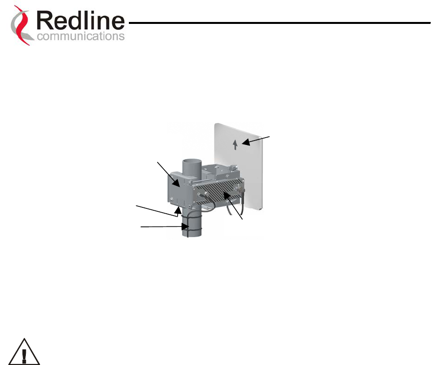
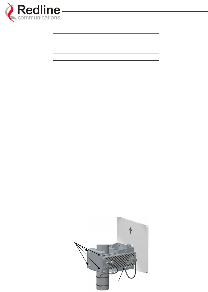
5.1. The AN-30 System’s T-58 Transceiver / Antenna at a Glance
A vertical mount bracket (Figure 6) is provided with the system.
Ground
Screw
Flat Plate
Antenna
T-58 Transceiver
Mount
Bracket
Pole
Figure 6: AN-30 Radio With Vertical Mount
The vertical mount bracket can accommodate 1 ¾” to 4 ½” (4.45 cm – 11.45 cm) OD
masts found on many commercial tower installations.
Before connecting the AN-30 system, it is important to review the safety
tips provided at the beginning of this manual.
Page 18 of 80
Redline Communications …..solving the first mile challenge
AN-30 System User Manual
6
6.
.
A
AN
N-
-3
30
0
S
Sy
ys
st
te
em
m
I
In
ns
st
ta
al
ll
la
at
ti
io
on
n
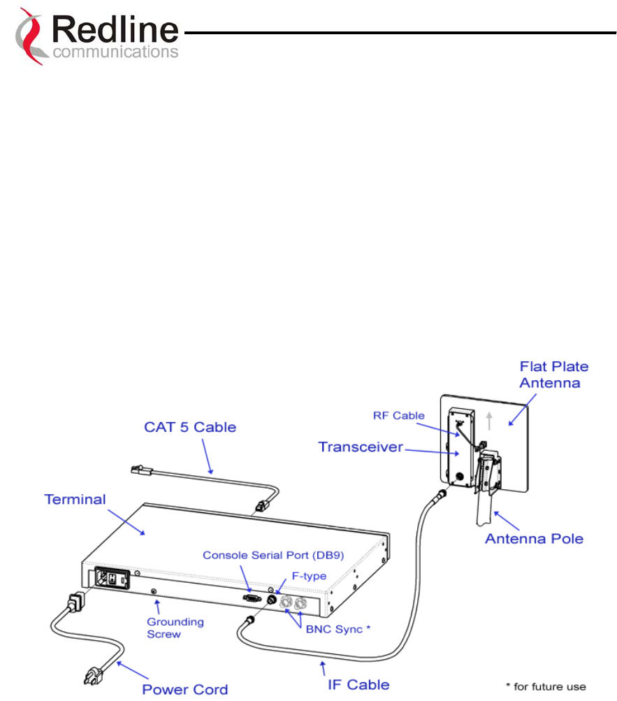
This section of the manual presents a basic overview of the steps required to install the
AN-30 terminal, outdoor transceiver, antenna and associated equipment.
Figure 7 below illustrates the primary system components and cables. The power cord
connects to a 110/220/240 VAC standard power outlet or to a 48 VDC, while the CAT
5/UTP cable (not included) connects the terminal to the data network via a standard
10/100BaseT Ethernet connection. The provided IF cable connects the terminal (located
indoors) to the T-58 Transceiver (located outdoors), and carries the transmitted and
received signal, DC power for the AN-30 radio, as well as control and reference signals.
Note that the provided IF cable is meant for exterior use, and should be used for only
minimal interior runs to connect to the terminal. Also note that the BNC connectors are
for future use.
Figure 7: AN-30 System Installation
(AC shown)
The terminal is for indoor installation only, while the transceiver and antenna (together
known as the AN-30 Radio) are mounted externally. The principal steps in installation are:
1. Conduct a general site survey
2. Install the antenna
3. Install the IF cable
4. Install the AN-30 terminal
5. Align the antenna
Each step is addressed in more detail below.
Page 19 of 80
Redline Communications …..solving the first mile challenge

AN-30 System User Manual
6.1. General Site Survey
The first step in installing the AN-30 system is to conduct a general site survey.
Although the installation steps are relatively straightforward, they do involve some
construction and electrical work, which is best performed by a professional installer.
The following site survey steps should be followed:
Determine the optimum location. The first key step in the deployment exercise is to
determine and identify building candidates that can be used to support the link. A critical
parameter to consider is the range at which the two terminals are required to operate.
Range performance is determined by empirical formulas that consider a number of
equipment and environmental factors described later in this manual. Ensure that the
installation sites meet these range performance requirements before moving to the next
step. You may use Redline’s Link Budget Tool to determine the expected performance of
the link. The Link Budget Tool can be obtained by contacting your Redline certified
partner or system integrator. See Section 10.3.1 on page 66 for more information. Verify
the accuracy of any building drawings/blueprints that may be available. The
installation process may require penetrating the building to run the IF cable between the
outdoor and indoor units. In this regard, it is imperative that the blueprints and/or
drawings of the building are up to date and accurate. It may also be possible for the IF
cable to be installed on the outside of the building leading to the antenna location on the
roof of the building.
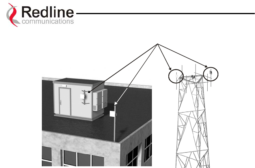
Identify the best path for the link. For maximum performance, it is recommended to
mount the antenna in a location where there is line of sight to the remote terminal. If
possible, the antenna should be positioned such that there is maximum clearance within
the first Fresnel zone of the direct path. The best means of achieving Fresnel zone
clearance is to mount the antennas as high as possible, on either a tall building or tower,
as shown in Figure 8 (Vertical mount system is shown).
The AN-30 system is also designed to operate in non-line-of-sight (NLOS) conditions, as
a result of the OFDM technology incorporated in the platform. Under NLOS conditions,
the best method of obtaining a proper RF link is to evaluate different antenna orientations
and choosing the one that results in the best Signal to Noise (SINADR) ratio and highest
Received Signal Strength (RSSI) value. Often, this can be achieved by introducing an RF
multipath condition by orienting the antennas towards a structure in sight of both the
local and remote antennas. If the obstruction in the path is not exceptionally high, it may
be possible to aim both antennas near the top of the obstruction. With the use of OFDM
in the Redline system, any additional multipath signals introduced will provide additional
opportunities for an improved link.
Page 20 of 80
Redline Communications …..solving the first mile challenge
AN-30 System User Manual
Radio
Deployments
Figure 8: Radio Deployment Options
Identify potential sources of RF interference. Test for possible RF interference on the
roof-top or tower by utilizing appropriate test equipment. RF interference arises from any
other wireless system operating within the same frequency band as the AN-30. Note that
the AN-30 system supports nine different overlapping channels within the 5.8 GHz band
and has the ability to use up to five of these channels at any one cell site; there is,
therefore, some flexibility in addressing or avoiding interference should other
transmitters in relatively close proximity present problems.
6.2. Installing The Antenna
Once the site survey has been completed and the exact location for the antenna identified,
the next step is to assemble and mount the radio onto either a building structure, pole or
tower.
Note there is an arrow on the back of the antenna, which must point in the same direction
for both the local and remote systems to ensure proper polarization when the antenna is
deployed (see Figure 7 above). Ensure the proper polarization is used for the antenna
before attaching the mounting bracket in the next step.
The vertical mount bracket is installed first. The antenna and mounting brackets have
been designed to withstand strong winds; it is imperative that all hardware for the
mounting brackets be securely fastened to avoid any movement which could introduce
misalignment.
Page 21 of 80
Redline Communications …..solving the first mile challenge

AN-30 System User Manual
The T-58 Transceiver is then mounted to the mounting bracket. This assembly is in turn
attached to the back of the antenna. Note the transceiver must be connected to the antenna
via the short RF cable provided.
For building mounts, ensure the surface to which the mounting bracket will be attached is
structurally sound, flat and vertical (use a level). Ensure that the installation can
withstand wind loading.
6.3. Running The IF Cable
The system is shipped with a 100 foot (30.5 m) length of RG6 IF cable to connect the
transceiver and indoor terminal. The IF cable carries the transmitted and received signal,
DC power for the AN-30 radio, and control signals. One hundred feet is the mandatory
minimum length; if a longer outdoor run is required, it is recommended that a single length
of the appropriate cable be used; coupling the provided 100 foot cable to another length
will result in increased attenuation. Refer to the cable requirements in the Specifications
section at the end of this manual.
Note: If male F-type crimp connectors are used with custom cables, the cable’s core
conductor diameter must be no larger than 1mm (.042 inches) or longer than 1cm (0.38
inches) to avoid damage to the T-58 and AN-30 connectors. If the core diameter exceeds
1mm, use soldered F-type connectors that do not exceed these dimensions.
The following steps define the cable installation process:
1. Run the cable alongside the antenna pole as shown. The IF cable is equipped with 75
ohm male F-type connectors at both ends. Ensure the cable is running downward as
shown to prevent water from accumulating on the connector. The cable should be
fastened to the pole to prevent movement or damage to the connector.
Figure 9: IF Cable
Page 22 of 80
Redline Communications …..solving the first mile challenge
AN-30 System User Manual
2. The RF cable should connect the antenna to the transceiver.
3. Connect the male IF cable connector to the female F-type connector on the
transceiver. The connector should then be weatherproofed with a standard
weatherproofing material for outdoor RF installations. Note that the provided IF
cable is for exterior use. It is recommended that the cable terminate at the exterior
wall using a grounding block, and that interior grade cable be used to connect the
terminal to the grounding block according to local codes. For convenience, a
grounding block is included with the AN-30 system. An optional lightning
arrestor may be used to protect the terminal and other indoor equipment from
sudden electrical surges. A suitable arrestor may be purchased through any of
Redline’s system integrators. Note that performance may be affected by the use of
other arrestors.
4. Connect the IF cable to the F-type female connector located on the back of the
terminal. The connector should be tightened finger-tight and then tightened an
additional 1/8 of a turn.
6.4. Installing The Terminal
Once the AN-30 terminal and the radio are connected, the terminal is ready to be installed
and configured. The Ethernet data port will automatically negotiate network speed
(10/100 Mbps) based on the capability of the device to which it is interfacing with.
If the terminal is used for connection to a core network, the network device is likely to be
a router, hub, or switch as shown in Figure 10. In this configuration, a cross-over
Ethernet cable is required to connect between the terminal and the network device.
Page 23 of 80
Redline Communications …..solving the first mile challenge
AN-30 System User Manual
Figure 10: AN-30 Terminal Connected To Switch / Router / Hub
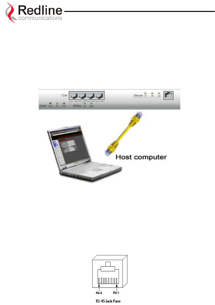
The AN-30 terminal may also be connected directly to the host computer, as shown in
Figure 11. In this configuration, a straight-through CAT 5/UTP cable is required to
complete the connection.
Figure 11: AN-30 Terminal Connected To Host Computer
To help you establish other implementations that are not addressed in this manual, Figure
12 provides an illustration of the pinout for the AN-30 terminal LAN interface.
Warning: do not connect a telephone cable to the AN-30 LAN interface, as this will
damage the terminal.
Page 24 of 80
Redline Communications …..solving the first mile challenge
AN-30 System User Manual
Jack Pin Function
1 Rx +
2 Rx -
3 Tx +
6 Tx -
Figure 12: AN-30 Terminal LAN Ethernet Port Pinout
Now connect the DC or AC cord to the AN-30 outlet and turn the terminal on using the
toggle switch at the rear of the unit. The system “Pwr” LED should illuminate green to
indicate power to the unit. The system is now ready to be configured. If the Pwr LED is
not on and/or the “Fault” LED illuminates red, there is a problem with the terminal.
6.5. Aligning The Antenna
Once the antenna is mounted and the terminal is installed, the antenna must be aligned in
both the azimuth and elevation planes. Elevation alignment is accomplished by
loosening the two bolts attached to the mounting bracket, as shown in Figure 13 below,
and angling the antenna so it is aligned towards the remote terminal. The azimuth
alignment is accomplished by loosening the bolts on the antenna bracket and rotating the
antenna until alignment is achieved. For basic tuning using actual signal strength, an
alignment "buzzer" (intermittent tone sweep generator) is available on the T-58
Transceiver. Faster repetitions of the tone sweep indicate better alignment. The buzzer is
enabled via the software interface described in section 0.
A
zimuth Adjustment
Bolts
Elevation Adjustment
Bolts
Figure 13: Aligning The Antenna - Vertical Mount
Page 25 of 80
Redline Communications …..solving the first mile challenge

AN-30 System User Manual
NOTICE
1 - The AN-30 System is used as a fixed wireless TDM and Ethernet bridge that requires
professional installation with specified antennas and output power levels certified under
the FCC Grant for AN-30 System for Point-to-Point or Point to Multipoint mode of
operations.
2 - FCC RF Exposure Requirements - The antenna(s) used for this transmitter must be
fixed-mounted on outdoor permanent structures with a separation distance of at least 3.0
meters (9.3 feet) from all persons and must not be co-located or operating in conjunction
with any other antenna or transmitter.
3 - The AN-30 System is certified by the FCC and Industry Canada with 5.8 GHz
directional antennas, listed below:
Table 1: FCC and Industry Canada Certified 5.8GHz Antennas
Model Number Antenna Gain, dBi Antenna Type Application
486001 28.0
Directional, planar array PMP & PTP
485002 23.0
Directional, planar array PMP & PTP
485024 21.0
Directional, flat panel PMP & PTP
484027 14.0
Directional, flat panel PMP & PTP
484026 15.0
Omni Directional, flat panel PMP
484025 14.0
Omni Directional, flat panel PMP
SP4-5.2 34.8
Directional, parabolic PMP & PTP
SP3-5.2 31.2
Directional, parabolic PMP & PTP
SP2-5.2 29.0
Directional, parabolic PMP & PTP
SP1-5.2 22.5
Directional, parabolic PMP & PTP
SEC-55V-60-17 17.0
Directional, sector PMP & PTP
SEC-55V-90-16 16.0
Directional, sector PMP & PTP
MPR58031PTNF 31.0
Directional, parabolic PMP & PTP
MPR58029PTNF 29.0
Directional, parabolic PMP & PTP
TDJ-5818AM-60 18.0
Directional, sector PMP & PTP
TDJ-5816AM-90 16.0
Directional, sector PMP & PTP
Note: For the most current FCC / IC approved antenna list please visit our web site at
www.redlinecommunications.com
4 - For fixed, point-to-point mode of operations, the transmitting antennas are specified in
the above table; the use of omni-directional antenna is prohibited for point-to-point
operation.
Page 26 of 80
Redline Communications …..solving the first mile challenge
AN-30 System User Manual
7
7.
.
S
Sy
ys
st
te
em
m
C
Co
on
nf
fi
ig
gu
ur
ra
at
ti
io
on
n
a
an
nd
d
O
Op
pe
er
ra
at
ti
io
on
n
V
Vi
ia
a
T
Th
he
e
C
Co
on
ns
so
ol
le
e
P
Po
or
rt
t
All operator communications with the AN-30 terminal may be made using a direct
connection to the serial Console Port on the back of the terminal. This section describes
the procedures for configuring and operating the AN-30 terminal via the Console Port
using the command line interface (CLI).
Connect a PC/Terminal to the AN-30 terminal’s serial port DB9 connector using a cross-
connect or null modem cable (DB9 female-female). Set the PC/Terminal to emulate a
VT-52 or VT-100 terminal, using the following port settings:
Bits Per Second:9600; Data Bits:8; Parity: None; Stop Bits:1; Flow Control: Hardware
Hit the ‘Enter’ key – the AN-30 prompt will appear.
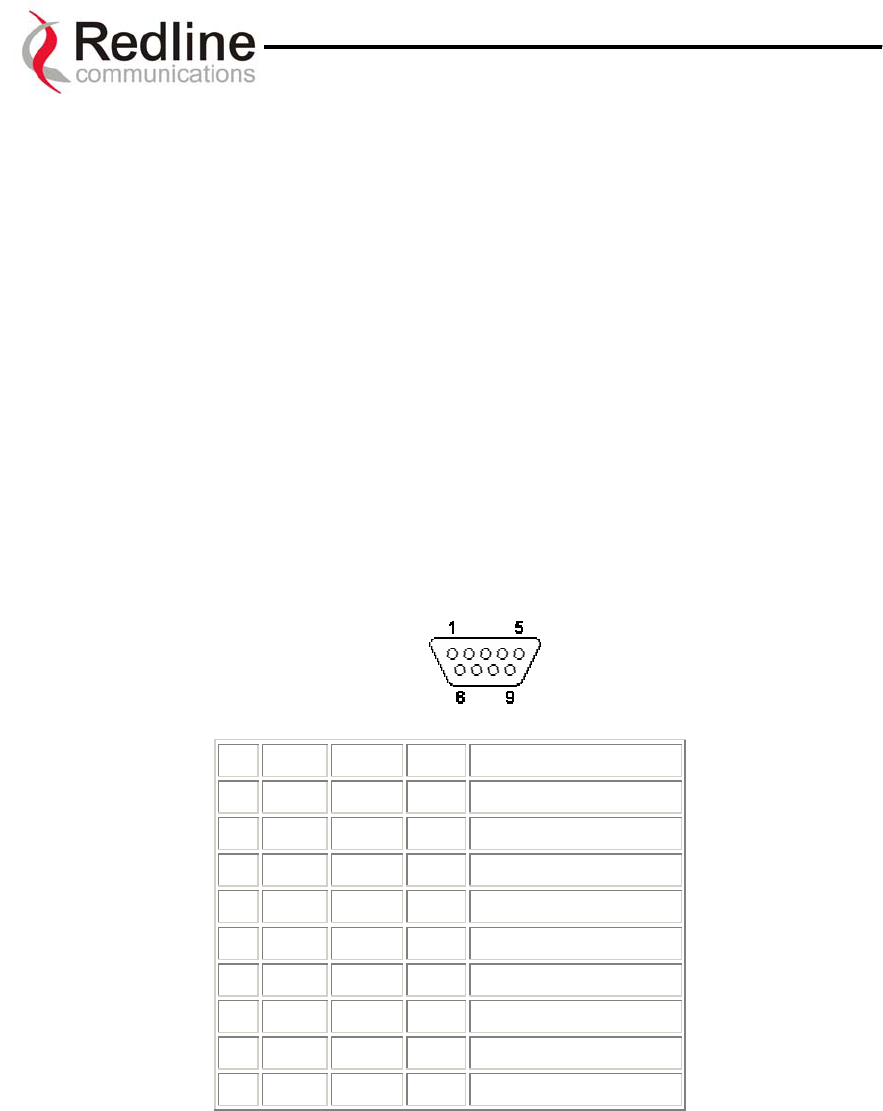
The diagram below shows the 9 PIN D-SUB male connector pinout at the AN-30
Terminal:
Pin Name RS232 V.24 Description
1 CD CF 109 Carrier Detect
2 RXD BB 104 Receive Data
3 TXD BA 103 Transmit Data
4 DTR CD 108.2 Data Terminal Ready
5 GND AB 102 System Ground
6 DSR CC 107 Data Set Ready
7 RTS CA 105 Request to Send
8 CTS CB 106 Clear to Send
9 RI CE 125 Ring Indicator
Note: RS232 column is RS232 circuit name.
Note: V.24 column is ITU-TSS V.24 circuit name.
The terminal may now be configured and queried using a set of CLI. Type ‘help’ for a list
of general commands.
AN-30 System User Manual
8
8.
.
S
Sy
ys
st
te
em
m
C
Co
on
nf
fi
ig
gu
ur
ra
at
ti
io
on
n
a
an
nd
d
O
Op
pe
er
ra
at
ti
io
on
n
V
Vi
ia
a
T
Te
el
ln
ne
et
t
All operator communications with the AN-30 terminal may be made using CLI over
Telnet. This offers the advantage of allowing the operator to access and control the AN-
30 terminal remotely from any geographical location, without the need for a web
browser. This section describes the procedures for configuring and operating the AN-30
terminal via Telnet using the command line interface (CLI).
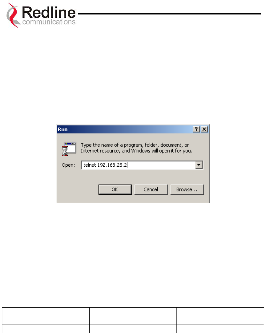
To connect to the terminal, Telnet to the IP address of the terminal (default address
shown below).
When the command prompt screen appears, login using the Username: admin and
Password: admin. The terminal may now be configured and queried using a set of CLI
commands. Type ‘help’ for a list of general commands.
The AN-30 is factory set with two login accounts; “Administrator” and “User”. Logging
in under the administrator account allows all privileges. Logging in under the user
account restricts the privileges to executing show and get operations only. The factory set
default values for each account’s username and password are given below:
Table 2: Factory Defaults For Account Username and Password Values
Account Username Password
Administrator admin admin
User user user
The administrator account’s default values, for both the username and password, are
factory set to “admin”. The user account’s default values, for both the username and
password are factory set to “user”.
Refer to the System Password screen to change the password for future sessions. If the
password is changed, record it in a secure location for future reference. Note that the
username cannot be changed for the Administrator account.
Page 28 of 80
Redline Communications …..solving the first mile challenge

AN-30 System User Manual
Wireless Configuration:
Max RF power: This parameter specifies the maximum power level of the system.
Depending on RF channel, FCC regulations and/or local /regional regulations, the user
must follow the table below when determining the power to be used.
Model
Number
Antenna
Gain, dBi
Antenna
Type
Application Min conducted
power (dBm)
Max conducted
power ratings (dBm)
EIRP limit
(dBm)
486001 28.0
Directional,
planar array
PMP -5.4 8 36
485002 23.0
Directional,
planar array
PMP -5.4 13 36
485024 21.0
Directional,
flat panel
PMP -5.4 15 36
484027 14.0
Directional,
flat panel
PMP -5.4 22 36
484026 15.0
Directional,
flat panel
PMP -5.4 21 36
484025 14.0
Directional,
flat panel
PMP -5.4 22 36
SP4-5.2 34.8
Directional,
parabolic
PMP -5.4 1.2 36
SP3-5.2 31.2
Directional,
parabolic
PMP -5.4 4.8 36
SP2-5.2 29.0
Directional,
parabolic
PMP -5.4 7.0 36
SP1-5.2 22.5
Directional,
parabolic
PMP -5.4 13.5 36
SEC-55V-
60-17 17.0
Directional,
sector
PMP -5.4 19.0 36
SEC-55V-
90-16 16.0
Directional,
sector
PMP -5.4 20.0 36
MPR58031
PTNF 31.0
Directional,
parabolic
PMP -5.4 5.0 36
MPR58029
PTNF 29.0
Directional,
parabolic
PMP -5.4 7.0 36
TDJ-
5818AM-60 18.0
Directional,
sector
PMP -5.4 18.0 36
TDJ-
5816AM-90 16.0
Directional,
sector
PMP -5.4 20.0 36
486001 28.0
Directional,
planar array
PTP -5.4 25.3 No limit
485002 23.0
Directional,
planar array
PTP -5.4 25.3 No limit
485024 21.0
Directional,
flat panel
PTP -5.4 25.3 No limit
484027 14.0
Directional,
flat panel
PTP -5.4 25.3 No limit
SP4-5.2 34.8
Directional,
parabolic
PTP -5.4 25.3 No limit
SP3-5.2 31.2
Directional,
parabolic
PTP -5.4 25.3 No limit
SP2-5.2 29.0
Directional,
parabolic
PTP -5.4 25.3 No limit
SP1-5.2 22.5
Directional,
planar array
PTP -5.4 25.3 No limit
SEC-55V-
60-17 17.0
Directional,
parabolic
PTP -5.4 25.3 No limit
SEC-55V-
90-16 16.0
Directional,
sector
PTP -5.4 25.3 No limit
MPR58031
PTNF 31.0
Directional,
sector
PTP -5.4 25.3 No limit
MPR58029
PTNF 29.0
Directional,
parabolic
PTP -5.4 25.3 No limit
Page 29 of 80
Redline Communications …..solving the first mile challenge

AN-30 System User Manual
TDJ-
5818AM-60 18.0
Directional,
parabolic
PTP -5.4 25.3 No limit
TDJ-
5816AM-90 16.0
Directional,
sector
PTP -5.4 25.3 No limit
A
AN
N-
-3
30
0
C
CL
LI
I
(
(C
Co
om
mm
ma
an
nd
d
L
Li
in
ne
e
I
In
nt
te
er
rf
fa
ac
ce
e)
)
f
fo
or
r
W
Wi
ir
re
el
le
es
ss
s
a
an
nd
d
E
Et
th
he
er
rn
ne
et
t
The CLI (Command Line Interface) System Configuration commands provide a simple to
use User Interface for the operator to input a complete set of system parameters for the
Ethernet, TDM card and Wireless components of the AN-30 terminal. The CLI command
format for Telnet and the RS-232 port is as follow:
<command> [parameter1] [parameter2] [parameter3]
8.1. CLI General Commands
chgver (Change Software Version): Swaps the operating and secondary software
versions
get (Get parameter value): Get <parameter name> displays the value for a status
parameter. For configuration parameters, use Set command.
login: Allows login under a different username and password
logout: Disconnects user from the terminal.
passwd (Change Password): passwd <username> <newpassword> Change password for
user.
reboot: Reboot <time in seconds> Reboots the terminal.
resetstats (Reset Statistics): Resets all statistics
save config (Save Configuration): Permanently saves system configuration settings.
This command is required to activate all Configuration settings set previously
save snmp (Save SNMP Configuration): Permanently saves SNMP configuration
settings. This command is required to activate all SNMP settings set previously.
set (Set parameter value): Set one configuration parameter: <parameter name>
[<value>]. Without <value>, ‘set’ returns the actual value for configuration parameters.
For status parameters, use the Get command.
Page 30 of 80
Redline Communications …..solving the first mile challenge

AN-30 System User Manual
show config (List Configuration): Returns a list of all System Configuration
parameters.
show log (List the log file): Returns a list of current system log entries.
show snmp (List SNMP Configuration): Returns a list of all SNMP communities and
related parameters.
show stats (List System Status): Returns a list of all System Status parameters.
test config (Test System Configuration): Allows testing of configuration settings for 5
minutes, after which the system reverts to the previously saved settings. To make settings
permanent use 'save' command.
upgrade (Software Upgrade): Begin a software upload.
upgrade <ipaddr> <filename>
8.2. CLI System Configuration Commands
To store the parameters into memory, the CLI Save Configuration command must be
used. This operation is recorded in the System Logs.
sysname (System Name): An alphanumeric identifier for the local terminal, which can
consist of any combination of letters and numbers up to 20 characters in length. The
default name for the system from the factory is set to WEB01. The name remains with
the system, even during power off states, until the operator re-types a new name using
this menu field.
sysdetails (System Details): Specifies the location of the unit, telephone number and/or
contact information of the network administrator. Can be up to 20 characters in length.
ipaddr (IP address): This field is used to provide an IP address for the local AN-30
terminal. The default address from the factory is 192.168.25.2. For the initial setup, the
terminal should not be connected to the Internet, i.e., the host computer should be
connected directly to the terminal Ethernet port, to avoid address conflicts with other
devices on a public network. Once an IP address has been set, the terminal can be
connected to the core network.
ipmask (IP Subnet Mask): This field is used to set the desired IP subnet mask. The
mask value is set to "255.255.255.0” (Class C subnet).
gateway (Default Gateway Address): Specifies the IP address of the default router /
gateway on the local Ethernet segment.
Page 31 of 80
Redline Communications …..solving the first mile challenge

AN-30 System User Manual
llmod (Link Length Mode): Specifies if the link length is calculated automatically or
manually.
llmode <param>
where:
- off: the system is automatically calculating the link length
- on: the system expect the user to enter the link length
llmu (Link Length Measurements Units): Specifies the current measurements units
used for the link length.
llmu <param>
where:
- off: the system defaults to miles
- on: the system will use kilometers
ll (Link Length): Specifies the actual length path that the wave need to travel.
ll <param>
where the parameter will represent the distance in miles or kilometers
flowctrl (Flow Control Enable): Flow control is a feature that Ethernet devices use to
pause transmission of incoming packets. If a buffer on the Ethernet port is overrun, the
port transmits a special packet (pause frame) that requests remote ports to delay sending
packets for a period of time. For more information, see Appendix 2 – AN-30 Support For
TDM explained.
telnet (Telnet Enable): Telnet is used to connect to remote devices, usually via Telnet
port 23. Once a Telnet connection is established, it is possible to log in using the ‘admin’
or ‘user’ user id and set the parameters of the unit using the CLI
telnetport (Telnet Port): The default Telnet port is 23. The port can be changed to any
other number between 23 and 65,000, excluding port 80.
set snmp (SNMP Enable / Disable): Specifies whether the Simple Network
Management Protocol (SNMP) agent is enabled. When this item is enabled, a listing of
the current SNMP communities and associated parameters can be viewed.
snmpcomm (Community Name): To add a new SNMP community:
snmpcomm add <community name> <access>
where <access> can be: "r","w","t" or any combination
To delete an SNMP community type: snmpcomm del <community name>
snmpaccess (Community Access): To modify access rights for a community type:
snmpaccess <community name> <access>
where <access> can be: "r","w","t" or any combination
- r (Read): use ‘Read’ to grant read access permission to members of this
community
Page 32 of 80
Redline Communications …..solving the first mile challenge

AN-30 System User Manual
- w (Write): use ‘Write’ to grant write access permission to members of this
community
- t (Trap): use “Trap” to grant read access permission to members of the trap
community
snmptrap (Trap Enable /Disable and Destination): To add a trap destination for an
SNMP community type:
snmptrap add <community name> <IP destination>
Or to delete a trap destination for an SNMP community:
snmptrap del <community name> <IP destination>
When the SNMP Agent in the AN-30 detects an error condition, a message known as a
trap is sent. A Trap Host is an IP workstation/server that is set up to receive SNMP trap
messages.
rfchannel (RF Channel): specifies the operating channel of the system, within the 100
MHz available in the 5.8 GHz band. The table below specifies the center frequencies of
each permitted channel.
Table 3: RF Channel Center Frequencies
Channel Frequency
1 5735 MHz
1A 5745 MHz
2 5755 MHz
2A 5765 MHz
3 5775 MHz
3A 5785 MHz
4 5795 MHz
4A 5805 MHz
5 5815 MHz
To avoid interference, two PTP links operating in the same physical location (co-located)
or within close proximity must be separated by at least one channel, i.e., the gap between
channels must be 20 MHz or more (e.g., channels 2 and 3). Refer to Section 10.4 for
further information regarding deployment conventions.
txpower (Max Tx Power): this parameter specifies the maximum power level of the
system. Depending on the RF channel and FCC regulations, the software will determine
the actual power to be used, which will not exceed this user defined value. Refer to Table
4 below. The Actual Tx Power is displayed on the System Status page.
The Actual Tx Power is set by the software / firmware to the maximum power permitted
for each channel according to the modulation scheme, as shown in the following table.
Page 33 of 80
Redline Communications …..solving the first mile challenge
*
Table 4: Max. Operational Power Per Channel (in dBm) vs. Modulation

AN-30 System User Manual
64QAM ¾
(54 Mb/s)
64QAM 2/3
(48 Mb/s)
16QAM ¾
(36 Mb/s)
16QAM ½
(24 Mb/s)
QPSK ¾
(18 Mb/s)
QPSK ½
(12 Mb/s)
BPSK ¾
(9 Mb/s)
BPSK ½
(6 Mb/s)
Max Tx
Power 14 15 19 20 20 20 20 20
adaptmod (Adaptive Modulation): checking this box sets the system to operate in
adaptive modulation mode. It is not recommended to keep the AN-30 in this mode as the
system will automatically change the modulation schemes thus errors can be introduced
to the TDM traffic. For systems that have upgraded with a high-speed data option, it is
recommended that the user set the modulation up to two levels below the maximum
achievable on the link. The user can define the desired modulation scheme by setting the
Uncoded Burst Rate parameter (see next item). If the current Uncoded Burst Rate meets
or exceeds this rate, the Wireless Signal LED on the front panel lights solid green. If
packet errors exceed one in one million, the system will automatically step down the
modulation scheme to maintain the link. The Wireless Signal LED will flash green if the
current Uncoded Burst Rate is lower than the configured Uncoded Burst Rate. If errors
continue when the system reaches the lowest order modulation scheme, the Signal and
Link LEDs will turn off to indicate a failed RF link.
The dynamic modulation mode can be disabled by un-checking the Adaptive Modulation
checkbox. In this manual mode, the user is required to set the Uncoded Burst Rate and
the Modulation Reduction Level (see below). To operate in manual mode, first sample
the link with Adaptive Modulation enabled, then switch to manual mode setting the
modulation scheme up to 2 levels lower than that achieved using adaptive modulation.
*Note:
In some countries outside of North America, the Maximum Operational Power Per
Channel with a given antenna is limited in accordance to maximum allowable EIRP
levels for the region
ubrate (Uncoded Burst Rate [Mb/s]): Defines the desired Uncoded Burst Rate for the
link. Obtaining a 64 QAM license key (see section 8.6) raises the available Uncoded
Burst Rate from the default 36 Mbps to 54 Mbps.
modreduct (Modulation Reduction Level): applies when Adaptive Modulation is
disabled. Specifies how many levels the system must drop in modulation during re-
transmission of erroneous wireless packets. The level can be set from 0-7, with 2 being
the recommended value.
master (Master Mode): Sets the AN-30 system to serve as the master system, while the
other AN-30 assumes a slave role. There are no consequences related to setting either
unit to serve as the master or slave. One and only one unit must be set as the master.
chgver (Software Version): Specifies the current version of the system software. Note
that software can be remotely downloaded into the AN-30 terminal. The system includes
sufficient memory to hold two independent software loads. The operator can specify
which software load is used in the system. See section 8.4 for additional details.
Page 34 of 80
Redline Communications …..solving the first mile challenge

AN-30 System User Manual
encrypt (Encryption Enable): Specifies whether over-the-air encryption is enabled.
Note that if encryption is enabled, it must be enabled on both the local and remote units,
otherwise no Ethernet packets can be transferred.
encryptkey (Encryption Key): Enter the MAC address of the remote terminal to enable
over-the-air data encryption. Note, if encryption is enabled and the MAC address is not
properly entered, no Ethernet packets can be transferred.
buzzer (Alignment Buzzer Enable): Enables the antenna alignment tone sweep
generator located in the T-58 Transceiver for fine tuning using actual signal strength.
Faster repetitions of the tone sweep indicate better alignment.
radio (Radio Enable): Specifies whether radio transmission is enabled.
save config (Save configuration): Saves the currently entered parameters.
test config (Test Configuration): Allows testing of the current settings for five minutes,
after which the system reverts to the previously saved settings. To make settings
permanent, click 'Save’.
reboot (System Reset): Resets all statistics and reboots the terminal.
8.3. CLI General Status Information Commands
The following is a brief description of each field of the CLI General Status Information
sysname (System Name): Identifies the local terminal. The factory default name for the
system is “WEB01”.
sysdetails (System Details): Specifies the location, telephone number and/or contact
information.
ubrate (Uncoded Burst Rate [Mb/s]): Indicates the current uncoded burst rate of the
system. With adaptive modulation, this data rate may change over time, depending on the
prevailing propagation conditions.
master (Master Mode): Indicates if the system is serving as the master or slave.
swver (Software Version): Specifies the software version in use.
starttime (Time Since System Start): Specifies the time [dd/hh/mm/ss] since the
system started.
Page 35 of 80
Redline Communications …..solving the first mile challenge
AN-30 System User Manual
macaddr (Ethernet MAC Address): Specifies the Ethernet MAC address used by the
local terminal.
ipaddr (IP Address): Specifies the IP address used by the local terminal.
ipmask (IP Subnet Mask): Specifies the IP Subnet Mask used by the local terminal.
gateway (Default Gateway Address): Specifies the IP address of the default router /
gateway on the local Ethernet segment.
ll (Link Length): Actual length of the path the wave travels
rflink (RF Link Established): "Yes" indicates the RF link with the remote terminal is
established. "No" indicates there is no RF link to the remote terminal. This indicator is
correlated to the Wireless Link LED.
rffreq (RF Channel Frequency): Specifies the center frequency of the channel in use.
Tx Power: Specifies the actual current transmit power level.
cableattn (Cable Attenuation): Indicates the attenuation of the signal over the IF cable.
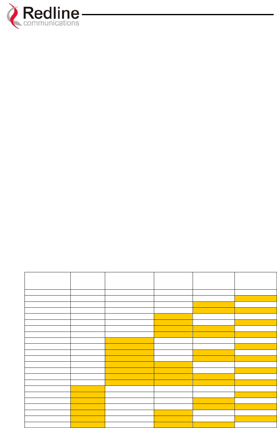
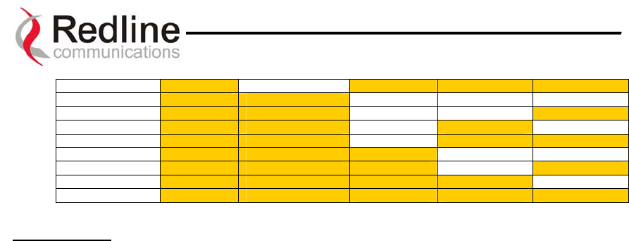
rfstatus (RF Status [Error Code]): An error code from 0-31 indicating the condition of
the RF components within the AN-30 terminal and T-58 Transceiver. See the RF Status
Error Code table below for details.
Table 5: RF Status Error Codes
Error Code AN-30
Terminal
PLL Error
Communication
Error Over IF
Cable
Radio
High Temp.
Warning
Radio Power
Supply Fault
Low DC Voltage
At Radio Input
0 - NO ERRORS
1
X
2
X
3
X X
4 X
5 X X
6 X X
7 X X X
8 X
9 X X
10 X X
11 X X X
12 X X
13 X X X
14 X X X
15 X X X X
16 X
17 X
X
18 X
X
19 X
X X
20 X X
21 X X X
22 X X X
Page 36 of 80
Redline Communications …..solving the first mile challenge
AN-30 System User Manual
23 X X X X
24 X X
25 X X X
26 X X X
27 X X X X
28 X X X
29 X X X X
30 X X X X
31 X X X X X
Error Details:
AN-30 PLL Error: The PLL (Phase Locked Loop) section within the AN-30 terminal
experienced an error. The System Fault LED may light. Try resetting the unit.
Communication Error Over IF Cable: Communication between the AN-30 terminal and
the T-58 Transceiver failed. Check the IF cable and connectors.
Radio High Temp. Warning: The T-58 Transceiver’s internal temperature rose above 185F
/ 85C. The transceiver will shut down for 30 seconds to allow cooling time.
Radio Power Supply Fault: Indicates a fault in the transceiver’s power supply. This error
could be due to a problem with the internal power supply, or with the power source from the
AN-30 terminal. If the Low DC Voltage At Radio error is also indicated, (see below) check
the IF cable and connectors. If the Low DC Voltage At Radio error is not indicated, the T-58
Transceiver will require servicing.
Low DC Voltage At Radio Input: The DC voltage at the transceiver (carried by the IF
cable from the AN-30 terminal) is lower than the required 24VDC. Check the IF cable and
connectors. The minimum required voltage for operation is 12VDC.
Ethernet LAN Statistics:
erxpkt (Rx packets): Counts the number of packets successfully received by the local
system.
erxpktd (Rx packets – Discarded): Counts the number of packet errors received by the
local system.
etxpkt (Tx Packets): Counts the number of Ethernet packets transmitted by the local system.
Wireless Statistics:
rssimin (Received Signal Strength – Min): Indicates the minimum received signal strength
measured since the last screen refresh.
Page 37 of 80
Redline Communications …..solving the first mile challenge

AN-30 System User Manual
rssimean (Received Signal Strength – Mean): Indicates the average received signal
strength, computed since the last screen refresh.
rssimax (Received Signal Strength – Max): Indicates the maximum received signal
strength measured since the last screen refresh.
sinadr (SINADR): Indicates the average signal to interference, noise and distortion ratio
measured since the last screen refresh. The ratio is based on the digital information provided
from the output of the A/D converter, and includes the effects of the AGC.
wrxpkt (Rx Packets): Indicates the number of wireless packets received over the air from
the remote terminal.
wrxpktr (Rx Packets – Retransmitted): Indicates the number of wireless packets
retransmitted over the air from the remote terminal.
wrxpktd (Rx Packets – Discarded): Indicates the number of wireless packets originating
from the remote terminal received over the air with errors due to degradation in the RF link.
wtxpkt (Tx Packets): Indicates the number of wireless packets (including Ethernet frames
and error correction bytes) successfully transmitted over the air by the local terminal.
wtxpktr (Tx Packets – Retransmitted): Indicates the number of wireless packets
retransmitted over the air by the local terminal. The retransmission scheme is based on the
Automatic Repeat Request (ARQ) algorithm that detects when packets are lost, and makes a
request to the MAC scheduler to repeat transmission of the lost packets.
wtxpktd (Tx Packets – Discarded): Indicates the total number of transmitted wireless
packets discarded by the remote terminal, due to degradation in the RF link.
resetstats (Reset Statistics): Click this button to clear the data for the Wireless and Ethernet
LAN Statistics on this page. You will be prompted for your password.
8.4. Upload Software
The CLI upload software command is used to upgrade the existing software load of the
AN-30 terminal with new software stored in a binary file on the server or host computer.
Note the AN-30 terminal contains two memory pages for storing two versions of the
software / firmware. The user can select the operating software version using the CLI
command. The upload will always overwrite the secondary (unselected) version;
therefore it is important to select the desired operating version before beginning the
upgrade process.
The upgrade process can be achieved remotely, using the Trivial File Transfer Protocol
(TFTP) over the Internet. Two input fields must be filled in by the operator: TFTP Server
Page 38 of 80
Redline Communications …..solving the first mile challenge

AN-30 System User Manual
IP Address and File Name. The TFTP Server IP Address is the IP address of the host
computer or server that contains the upgrade software in binary format, while File Name
is the name of the actual binary file.
The CLI command for software upload is: upgrade <ipaddr> <filename>
After typing the TFTP Server IP Address and File Name, type enter to begin the file
transfer. The upgrade file size is approximately 1.9 MB, and will take approximately two
to four minutes to download from the server to the AN-30 terminal memory. To activate
the new version, it is necessary to swap the operating and the secondary software version
with the CLI command chgver.
Upon successful transfer of the file, the terminal will verify the integrity of the new
software. If errors were introduced during the transfer process as a result of (for example)
link degradation, the AN-30 terminal will reject the new software load and provide a
warning that the upgrade was unsuccessful. In this case, the operator will need to repeat
the upload process.
8.5. System Password
The factory default password for the system is "admin" for the administrator’s ID, and
“user” for the user’s ID. To change the password, use the CLI command:
passwd <username> <newpassword>
using any alphanumeric combination for the password. Note the field is case sensitive
and can be up to 16 characters in length.
For more information on password related issues, see section 8 on page 28.
Note: depressing the front panel Reset button for more that five (5) seconds will restore
the factory default passwords.
8.6. AN-30 Options
Through the License Key (an optional purchase item) the following product features can
be enabled:
• Add an additional one (1) or three (3) E1/T1 ports to the existing default single
(1) port
• Add high speed data access to increase the throughput capacity beyond the basic
Ethernet access provided by default on all systems.
Note:
Page 39 of 80
Redline Communications …..solving the first mile challenge

AN-30 System User Manual
Basic Ethernet access is provided solely for the purpose of managing the AN-30
system. Using this port for user data traffic requires installation of the high speed data
option in order to avoid impacting TDM performance.
The key is personalized to each unit’s MAC address. Please ensure that the correct MAC
address is provided when requesting a key from your local Redline representative, or
register directly at http://www.redlinecommunications.com/support/register.
Use the following CLI command to enter the “Option Key”:
set optionskey <key_value>
Note, if the key_value is not correctly entered, it will not be saved and the options will
not be selected. Please note that the option key is case sensitive.
8.7. System Logs
The System Logs page, shown in Figure 14, provides a list of the last forty messages
recorded by the AN-30 terminal, describing either system activity or errors that have
occurred.
108-Version control loaded successfully!
103-Parameters saved successfully!
100-Parameters loaded successfully!
101-Firmware configuration OK!
106-Firmware programmed OK!
111-SNMP configuration loaded successfully!
103-Parameters saved successfully!
105-Password changed successfully!
Figure 14: System Logs Screen
The show log CLI command can be use in order to display the log file.
The logs will also indicate if the following transactions were successfully completed:
• Save Configuration – Under the Configuration screen.
• Upload – Under the Upload Software screen.
• Change Password – Under the System Password screen.
• Send Options Key
The following table provides a brief description of the key messages recorded in the logs
by the system:
Log Message Description
100-Parameters loaded successfully! All system parameters have been successfully downloaded.
101-Firmware configuration OK! The onboard firmware configuration has been properly set up.
102-Ethernet port configured! The Ethernet port has been properly configured and is
operational.
Page 40 of 80
Redline Communications …..solving the first mile challenge

AN-30 System User Manual
103-Parameters saved successfully! The latest configuration parameters have been successfully
saved into the system memory.
104-Upgrade OK! The software upgrade process completed successfully.
105-Password changed successfully! The system password was successfully changed.
106-Firmware programmed OK! The firmware was successfully programmed.
107-Statistics initialized! Reset of statistics was successful.
108-Version control loaded successfully! Software version control data was successfully loaded.
109-Options Key activated! Product Options Key was accepted.
110-Options Key already used! The Product Options Key was not accepted because it was
already used once. Contact your local Redline representative.
111-SNMP configuration loaded
successfully!
The SNMP configuration was successfully loaded.
201-EEPROM corrupted. Def. param.
loaded!
The memory area containing the system configuration has been
corrupted. Default parameters loaded.
202-Error while saving parameters! The latest configuration parameters have not been successfully
saved. In this case, repeat the save configuration process to try
to resolve the problem.
203-Another upgrade in progress! The system is already in upgrade mode, in the event the operator
inadvertently invoked multiple simultaneous upgrades.
204-Invalid upgrade parameters! The parameter entered is in error. If this message appears, check
for typing errors.
205-Upgrade failed! The software upgrade process completed unsuccessfully.
206-Password changed unsuccessfully! The new password entered into the system was not successful.
In this case, repeat the process.
207-Timeout on reading data packet! The system has timeout looking for packets from the host
computer or server. Check for obvious problems such as
disconnected or faulty cable.
209-TFTP error received! The Trivial File Transfer Protocol (TFTP) routine used to
download the software to the AN-30 terminal during the
Upgrade process failed. Likely cause is disconnected or faulty
cable.
210-Error: TFTP unknown message! The TFTP client received an unknown message. In this case,
repeat the upgrade process.
211-Error: while writing flash!
While writing the new software into AN-30 terminal flash
memory an unexpected error occurred. Try to repeat the process
and if the error persist contact your local Redline representative.
212-Error firmware configuration! An unexpected error occurred while writing the onboard
firmware configuration. Try to repeat the process.
213-Firmware programming failed! The firmware programming failed.
214-Error while loading version control! Software version control data was not loaded successfully.
215-Log buffer full! The log buffer overflowed.
216-Invalid Options Key! User entered an invalid Product Options key.
217- PLL unlocked! One or more RF synthesizers unlocked. The unit stopped RF
transmissions and attempted to reprogram the synthesizers. If
this message repeats or if the RF link is not back on, try to reset
the terminal. If the problem persists, contact customer support.
218-Outdoor unit over temperature! The T-58 Transceiver's internal temperature rose above 185F /
85C. The transceiver will shut down for 30 seconds to allow
cooling.
219-Excessive DC loss on IF cable! The DC voltage at the transceiver (carried by the IF cable from
the AN-30 terminal) is lower than the required 24VDC. Check
the IF cable and connectors.
220-Outdoor unit power supply fault! Indicates a fault in the transceiver's power supply. This error
could be due to a problem with the internal power supply, or
with the power source from the AN-30 terminal. If the
'Excessive DC loss on IF cable' error is also indicated, check the
IF cable and connectors. If not, the T-58 Transceiver will require
servicing.
221-\public\ community can't be deleted! The default 'Public' SNMP community cannot be deleted.
222-Max.communit
y
number alread
y
No more communities ma
y
be defined, as the maximum number
Page 41 of 80
Redline Communications …..solving the first mile challenge

AN-30 System User Manual
defined! has been reached
223-Community name already defined! The name for the SNMP community has already been used.
Choose another name.
224-MIB initialization error! MIB construction process generated an error. Try to reset the
terminal. If the problem persists, contact customer support.
225-Error while loading SNMP
configuration!
EEPROM memory was corrupted and the SNMP configuration
couldn't be loaded. Default SNMP configuration was loaded.
226-Error while saving SNMP
configuration!
SNMP configuration saving process wasn't successfully. Try
again. If the problem persists, contact customer support.
Page 42 of 80
Redline Communications …..solving the first mile challenge
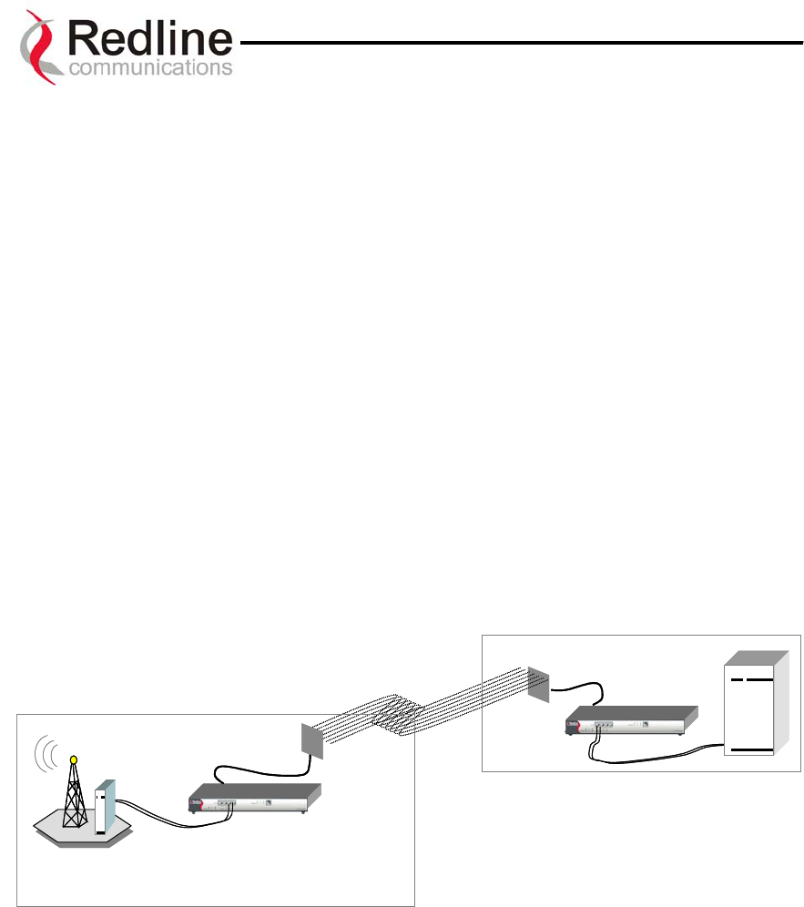
AN-30 System User Manual
9
9.
.
A
AN
N-
-3
30
0
C
CL
LI
I
(
(C
Co
om
mm
ma
an
nd
d
L
Li
in
ne
e
I
In
nt
te
er
rf
fa
ac
ce
e)
)
f
fo
or
r
t
th
he
e
T
TD
DM
M
c
ca
ar
rd
d
9.1. DS0 Bundles
The AN-30 supports distribution of the T1/E1 traffic across 4 sites in a cascaded PTP
topology.
To uniquely identify traffic that is destined to a specific site, requires the definition of
DS0 Bundles.
A DS0 bundle is a logical grouping of a specified number of timeslots. At least one
bundle is required for each physical T1/E1 port. DS0 Bundles can be defined starting at
any TS and running contiguously from 1 to a maximum of 24+1 timeslots (for T1 links)
and a maximum of 32 timeslots (for E1 links). An AN-30 can support a maximum of 4
DS0 Bundles.
Figure 15 illustrates a typical single hop PTP configuration back hauling 2 full rate T1/E1
lines in a mobility application. All traffic is terminating at a the same endpoints and
therefore requires definition of one DS0 bundle for each T1/E1 line.
BTS Site B
AN-30T
AN-30T
Base Station Controller Site
BTS Site B
AN-30T
AN-30T
Base Station Controller Site
Figure 15 Typical PTP ‘single hop’ configuration.
Figure 16 illustrates a cascaded multi-hop configuration where 4 DS0 Bundles are
required, one for each T1/E1 line.
Page 43 of 80
Redline Communications …..solving the first mile challenge
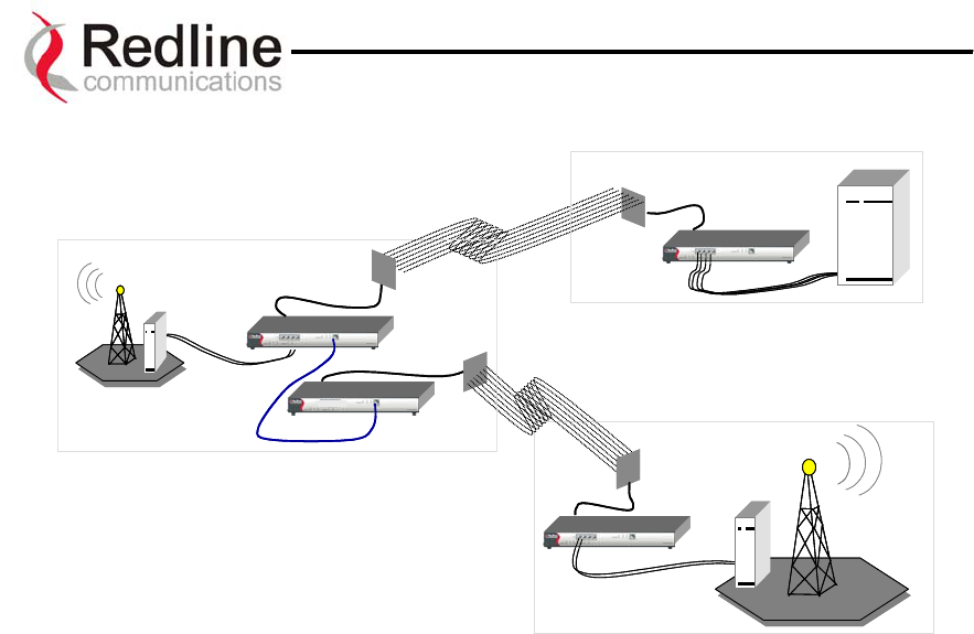
AN-30 System User Manual
AN-30T
AN-30T
BTS Site A
AN-30T
AN-30T
BTS Site A
BTS Site B
AN-30T
AN-50
Base Station Controller Site
BTS Site B
Base Station Controller Site
AN-30T
AN-50
Figure 16 Typical PTP ‘multi-hop’ configuration
9.2. Command Line Interface
The command line interface is used to configure the T1/E1 capabilities via the AN-30’s
console port or through a telnet session. The command set is divided into 5 categories,
Control, General, Serial Interface, DS0 Bundle, and Statistics. The General, Serial
Interface and DS0 Bundle categories supports 3 distinct operations, a get operation, a set
operation and a show operation.
The tdm get operation is used to retrieve the specified parameter value from a running
configuration of an active system.
The tdm set operation is used to modify the specified parameter value in the temporary
configuration.
The tdm show<category> operation is used to list all parameter values of the specified
command category for either the running configuration or the startup configuration.
All commands conform to the following syntax:
<command operation> <command> <command target> <parameter value>
The <command target> field, is only used by the Serial Interface and DS0 Bundle
category of commands:
The <parameter value> field is only required when issuing a tdm set operation.
Page 44 of 80
Redline Communications …..solving the first mile challenge
AN-30 System User Manual
The tdm get operation requires only the <command> <command target> fields to be
specified.
9.3. Quick Setup
The sequence of operations and the commands necessary to quickly configure the TDM
portion of the AN-30 are indicated below. All commands in bold face text must be
specified.
Define
General
Parameters
Define
Serial Interface
Parameters
Define
DS0 Bundle
Parameters
hostname
ipaddr
ipmask
gateway
vlandata
vlanvoice
clock
syncon
idlecode
key
softver
coding
framing
Lbo (T1 only)
tsbegin
tsnum
destbundle
destip
jitterbuf
packetlen
Define
General
Parameters
Define
Serial Interface
Parameters
Define
DS0 Bundle
Parameters
hostname
ipaddr
ipmask
gateway
vlandata
vlanvoice
clock
syncon
idlecode
key
softver
coding
framing
Lbo (T1 only)
tsbegin
tsnum
destbundle
destip
jitterbuf
packetlen
When setting up two AN-30s to form a wireless link the following steps must be
completed in the sequence shown below:
Local & Remote
Define
General
Parameters
Local & Remote
Define
Serial Interface
Parameters
Local & Remote
Define
Bundle
Parameters
ipaddr
ipmask
gateway
vlandata
vlanvoice
clock
coding
framing
Lbo (T1 only)
tsbegin
tsnum
jitterbuf
packetlen
Local AN-30
Bundle
Parameters
destbundle
destip
Remote AN30
Bundle
Parameters
destbundle
destip
Step 1 Step 2 Step 3 Step 4 Step 5
Local & Remote
Define
General
Parameters
Local & Remote
Define
Serial Interface
Parameters
Local & Remote
Define
Bundle
Parameters
ipaddr
ipmask
gateway
vlandata
vlanvoice
clock
coding
framing
Lbo (T1 only)
tsbegin
tsnum
jitterbuf
packetlen
Local AN-30
Bundle
Parameters
destbundle
destip
Remote AN30
Bundle
Parameters
destbundle
destip
Step 1 Step 2 Step 3 Step 4 Step 5
Subsequent sections discuss each of these commands in specific detail.
Page 45 of 80
Redline Communications …..solving the first mile challenge
AN-30 System User Manual
9.4. Configuration
The AN30 maintains 3 TDM configuration images,
Temporary
Configuration
Running
Configuration
Startup
Configuration
tdm_start tdm_save
tdm_copy
Temporary
Configuration
Running
Configuration
Startup
Configuration
tdm_start tdm_save
tdm_copy
• Temporary Configuration
• Running Configuration
• Startup Configuration
Through these distinct images the actions of
modifying the temporary configuration, and
activating a modified configuration are separated. T
operator can therefore make all changes in advan
the actual cut over without impacting the unit’s
current operation.
he
ce of
The following sections describe the complete T1/E1 command set and their associated
parameters.
9.5. Control commands
The control commands are used to manipulate the contents of each of the configuration
images as well as to save and activate, a specific configuration. There are 4 control
commands:
• tdm start
• tdm exit
• tdm save
• tdm copy
tdm start, no params.
This command synchronizes the temporary configuration with the running configuration.
Before making any changes to the temporary configuration you must first issue the tdm
start command to copy the running configuration into the temporary configuration
image.
tdm exit, no params.
This command discards all changes made to the temporary configuration.
Clearing the temporary configuration avoids the possibility of inadvertently loading a
modified configuration in the event that a tdm save command being accidentally issued.
This command should always be issued to leave the temporary configuration image
synchronized with the running configuration.
Page 46 of 80
Redline Communications …..solving the first mile challenge

AN-30 System User Manual
tdm save, no params
This command copies the temporary configuration image to the running configuration
image.
Since all commands falling under general, serial interface, and DS0 bundle categories,
modify only the temporary configuration image, the tdm save command is used to
activate these changes, by copying them to the Running configuration image.
Warning:
This command will reset operation of a working AN-30 link disrupting all
communications while the unit re-initializes to the new configuration. On a production
network this command should only be issued during the off hours of a maintenance
window.
The tdm save command triggers the following actions:
• The modified temporary configuration is checked.
• If valid, config is saved to running config and software is restarted.
• If configuration is not valid (i.e.: serial interface pointed by ”syncon” is
disabled), an error code is returned containing 3 fields: LEVEL + NUMBER +
ERROR_ID and “save” command is ignored.
The meaning of the error code bytes is presented in the following:
Level Definition
0 General Level
1 Serial Interface Level
2 Bundle Level
Level Number Definition
General 0 Always 0
Serial 1..4 the number of the misconfigured serial interface.
Bundle 1..128 the number of the misconfigured bundle.
Level Error ID Definition
0 GENERAL_SYNCON
1 GENERAL_TOO_MANY_BUNDLES
General
2 GENERAL_LINE_TYPE
0 SERIAL_BUNDLES_OVERLAP
1 SERIAL_TOO_MANY_BUNDLES
2 SERIAL_CODING
Serial
3 SERIAL_FRAMING
0 BUNDLE_TS0
Bundle 1 BUNDLE_MASK
Page 47 of 80
Redline Communications …..solving the first mile challenge

AN-30 System User Manual
Error codes are described in the following table:
Error Code Description
0:0:1 Too many bundles: if user defines more than the internal bundle
limit for the current software release
0:0:2 Line type (T1 or E1) is disabled in option key
0:0:3 Error at “syncon” parameter: if clocking is “loopback” and the
serial interface selected for synchronization has no bundles
defined, or if clocking is “adaptive” and there is no exactly one
bundle defined
1:x:0 Bundles defined on the serial line “x” have timeslots overlapping,
x=1…4
1:x:1 The serial line “x” is unframed and the user defined more than one
bundle, x=1…4
1:x:2 Wrong line coding for the serial line “x”, x=1…4
1:x:3 Wrong line framing for the serial line “x”, x=1…4
2:y:0 The bundle “y” contains timeslot 0 and the corresponding serial
line is framed, y=1…128
2:y:1 Too many timeslots selected for bundle “y”, y=1…128
tdm copy, no params
This command copies the current running configuration into the Startup configuration.
A running configuration is stored in volatile memory and will be lost in the event of a
system reset.
Therefore, once you are satisfied with a new configuration, the tdm copy command must
be issued to store the new configuration into the Startup Image. This is the only way to
permanently save an operating configuration. In order to insure the integrity of the saved
image all real-time tasks are halted during execution of the tdm_copy command.
Warning:
This command will reset operation of a working AN-30 link disrupting all
communications while the unit re-initializes to the new configuration. On a production
network this command should only be issued during the off hours of a maintenance
window.
Each time the unit is powered it will automatically load the last configuration that was
copied to the Startup Image.
9.6. General configuration commands
General commands are the set of commands that do not require the <command target>
field, and therefore are global in scope.
Page 48 of 80
Redline Communications …..solving the first mile challenge

AN-30 System User Manual
Set/Get Operations
The general set/get operations have the following syntax:
tdm set <command> <parameter value>
tdm get <command>
The get operation returns values from running configuration, the set operation applies to
the temporary configuration. The changes made by set operation become active only after
the tdm save command is successfully executed.
The general command set is as follows:
hostname
ipaddr
ipmask
gateway
vlandata
vlanvoice
clock
syncon
idlecode
key
line
softver
fanstate
The parameter for each command is valid only if used with the set operation.
hostname, params: HOST
The hostname of the T1/E1 module.
ipaddr, params: IP address in format a.b.c.d
The IP address of the T1/E1 module.
The TDM module in the AN-30 is uniquely identified by its IP address. The IP
address is used with the destip command to direct TDM traffic to a specific AN-30
end point.
By uniquely addressing the TDM module within the AN-30 it is possible to relay
traffic through an intermediate set of AN-30s without terminating the TDM stream.
The intermediate AN-30s can therefore act as a repeater while also providing Add
Drop Multiplexing (ADM) functionality as shown in Figure 16.
ipmask, params: IP mask in format a.b.c.d
The network mask. Not implemented for tdm_set operation
Page 49 of 80
Redline Communications …..solving the first mile challenge

AN-30 System User Manual
gateway, params: IPGATEWAY in format a.b.c.d
The IP address of the default gateway. Not implememted for tdm set operation
vlandata, params: VID_DATA
The VLAN ID used to tag all ingress traffic at the data port of the AN-30.
The VID_DATA parameter should be a decimal number between 0 and 4095
vlanvoice, params: VID_VOICE
The VLAN ID used to tag all TDM traffic from the T1/E1 Serial Interface ports 1 to 4.
The VID_VOICE parameter should be a decimal number between 0 and 4095
clock, params: CLK_IND
The clocking information on the T1/E1 module.
Parameter CLK_IND has the following meaning:
CLK_IND Definition
0 internal
1 loopback
2 adaptive
Internal clocking should be selected to set the AN-30 as the T1/E1 transmit clocking
reference.
Loopback clocking (aka network clocking) should be selected to have the AN-30
extract it’s T1/E1 transmit clock from the T1/E1 receive signal of a serial interface
port.
Adaptive clocking should be selected, at the remote side of the wireless link, to have
the AN-30 continuously adapt its T1/E1 transmit clock. In the case of adaptive
clocking the AN-30 uses its internal clocking reference and adapts its transmit clock
based on information extracted from the fill level of the jitter buffer for the serial
interface port specified with the syncon command. On a typical link one AN-30 is
always set to adaptive clocking, while the other end can be set for internal or
loopback.
syncon, params: SYNC_ON
Parameter SYNC_ON must be specified if clocking is set to ‘loopback’ or ‘adaptive’.
SYNC_ON specifies the serial interface port to be used as clocking reference. In this
case, the designated serial interface MUST have at least one active bundle at the time
“tdm save” command is issued, otherwise “tdm save” will return non-ack. If clocking
is ‘internal’, this command is ignored.
idlecode, params: IDLECODE
The idle code for unused timeslots on all of the serial interface ports.
Page 50 of 80
Redline Communications …..solving the first mile challenge

AN-30 System User Manual
If the idle code command is not specified, the default value 0xFF is used.
key, no params.
This is used only with a get operation: tdm get key
This command will get the option key (permitted line types, number of lines, user
data) on the T1/E1 module.
KEY fields
Bit7..5 Bit4 Bit3 Bit2 Bit1..0
unused
1 -
Enable
User
Port
1- Enable
T1 line
type
1 -Enable
E1 line
type
00-1 line
01-2 lines
10-4 lines
11-reserved
line, params: LINE_TYPE
This command will set the line type on the T1/E1 module (if permitted by the option
key).
LINE_TYPE Definition
0 T1 line
1 E1 line
softver, no params
This command is used only with a get operation. Represents the coded software
version.
fanstate, no params
This command will return 1 if the fan is ON (working) and return 0 if the fan is OFF
(not working).
Show Operations
The show operation is:
• tdm showgen
tdm showgen, params: CONFIG
This command is used to get the general configuration parameters from running or
startup config.
The default configuration selected is running config.
CFG Definition
0 running config
1 startup config
Page 51 of 80
Redline Communications …..solving the first mile challenge

AN-30 System User Manual
• tdm showactivebundles
tdm showactivebundles, no params
This command is used to return the number of active bundles and list the Ids of those
bundles
9.7. Serial interface configuration commands
Set/Get operations
The general set/get operation has the following syntax:
tdm set <command> <serial interface number> <parameter value>
tdm get <command> <serial interface number>
The get operation returns values from the running configuration. The set operation
applies to the temporary configuration. The changes made by set operation become
active only after the “tdm save” command is successfully executed.
In the following commands, the “serial interface number” (SN) parameter must be a
valid serial interface number (i.e.: for 4 T1/E1 valid values are 1, 2, 3, and 4), otherwise
the command will return non-ack.
The commands for serial interface configuration are:
• coding
• framing
• lbo
The second parameter for each command is valid only if used with the set operation,
as indicated below.
coding, params: SN, COD_IND
Defines the line coding type for the current serial interface on T1/E1 module.
COD_IND Definition
0 B8ZS
1 AMI
2 HDB3
framing, params: SN, FRM_IND
Defines the framing type of the current serial interface on T1/E1 module.
FRM_IND Definition
0 ESF
1 D4
Page 52 of 80
Redline Communications …..solving the first mile challenge
AN-30 System User Manual
2 CRC4
3 FAS
4 unframed
lbo, params: SN, LBO_IND
Defines the LBO parameter of the current serial interface on T1/E1 module.
This command has effect only on T1 modules.
LBO_IND Definition
0 0dB
1 -7.5dB
2 -15dB
3 -22.5dB
Show operations
The show operation is:
• tdm showserial
tdm showserial, params: SN, CFG
This command is used to get the serial interface parameters pointed by SN from running
or startup config.
If the CFG parameter is not specified the running config is selected by default.
CFG Definition
0 running config
1 startup config
9.8. DS0 Bundle configuration commands
A DS0 bundle is a logical mapping of a number of timeslots from the same physical
T1/E1 port.
The starting timeslot selected (ts_begin) is:
ts_begin = 0 if the line is unframed. In this case the number of selected ts must be 32 for
E1 or 24+1 for T1.
1<= ts_begin<=31(24 for T1) and tsnumber<=32-ts_begin (<=24+1-ts_begin for T1)
for framed. In this case the number of selected ts must be less than or equal to 31-
ts_begin (24 - ts_begin for T1). If multiple DS0 bundles are defined for the same line,
they must not overlap. So valid value will be:
for E1 ts_begin=1, ts_num=31
for T1 ts_begin=1, ts_num=24
Page 53 of 80
Redline Communications …..solving the first mile challenge

AN-30 System User Manual
The line that correspond to a DS0 bundle is selected based on the ID of the circuit
group:1-32 line 1, 33-64 line 2, 65-96 line3, 97-128 line 4.
Set/Get Operations
The general set/get operations have the following syntax:
tdm set <command> <bundle number> <parameter value>
tdm get <command> <bundle number>
The get operation returns values from the running configuration, while the set operation
applies only to the temporary configuration. The changes made by set operations become
active only after the “tdm save” command is successfully executed.
In the following commands, the value of BN (Bundle Number) is used to indirectly
specify the Serial Interface to which it applies. The value of BN must be specified as
32*SN-31<=BN<=32*SN (Serial Interface Number) in order for the commands to
execute successfully.
The following valid values for BN result:
Serial Interface Number Minimum BN Value Maximum BN Value
1 1 32
2 33 64
3 65 96
4 97 128
The bundle configuration commands are:
tsbegin
tsnum
destbundle
destip
jitterbuf
packetlen
Command Descriptions:
A bundle is automatically created through the definition of its associated parameters. The
commands tsbegin and tsnum are used to define the range of timeslots that are mapped
to specified bundle.
Valid values for TSB are 1 to 31 for E1 and 1 to 24 for T1 for framed and only value 0
for unframed. Valid values for BN are given in the table above.
The second parameter for each command is valid only if used with set operations
tsbegin, params: BN, TSB
This command defines the first active timeslot of the specified bundle BN.
Example:
tsbegin, 1, 1 (Creates the bundle 1 (corresponding to serial 1), beginning
with timeslot 1 from serial interface 1)
Page 54 of 80
Redline Communications …..solving the first mile challenge

AN-30 System User Manual
tsnum, params: BN, TSN
This command defines the number active timeslots in the specified bundle BN.
Example:
tsnum, 0, 30 (assigns to bundle 1, 30 contiguous timeslots starting at
timeslot 1 up to timeslot 30)
In this example assuming an E1 serial interface, the full channelized E1
line is mapped to a single bundle, 1.
destbundle, params: BN, DESTB
This command identifies the destination bundle, at the remote end, that maps to the
specified bundle BN.
The DESTB parameter is used to map the channels assigned bundle BN to a specific
bundle at the remote end. This allows the flexibility to remap the channels to different
timeslots at the remote location, effectively performing a cross-connect function over
the air.
destip, params: BN, DEST_IP in format a.b.c.d
This command identifies the destination IP address, of the remote end TDM module,
that has defined on it, the destination bundle for the specified bundle BN.
The DEST_IP parameter is the IP address of the remote end TDM module. This is the
IP address that was assigned to the TDM module using the general command ipaddr.
jitterbuf, params: BN, JBLEN
This command specifies the jitter buffer length in milliseconds for the specified
bundle BN. Allowed values for JBLEN: 5..300ms.
The jitter buffer is used to compensate for any delay variation that may occur during
transport of the ethernet encapsulated traffic. For delay sensitive applications, such as
TDM voice, the buffer is typically set below 10 msec, while more data centric
applications would employ a buffer that is closer to 300 msec. In order to minimize
latency this parameter should be set to the lowest value possible, without triggering
errors on the TDM interfaces.
Note:
For the lowest latency the Ethernet data port must be inactive with the AN-30 used
exclusively for TDM transport. Utilizing the Ethernet port for either in-band
management, or user data transport will require an increase in the jitter buffer
setting, proportional with the Ethernet port’s throughput.
packetlen, params: BN, PLEN
Defines the packet length to be used by the bundle BN.
Allowed values for PLEN: 64..1024 bytes.
Page 55 of 80
Redline Communications …..solving the first mile challenge

AN-30 System User Manual
Show operations
The show commands are:
- tdm showbundle
tdm SHOW_BUNDLE, params: BN, CFG,
This command is used to retrieve the bundle parameters for the specified BN from
either the running or startup config.
The default configuration selected is running config.
CFG Definition
0 running config
1 startup config
Other commands
Other commands are:
- tdm delbundle
tdm delbundle, params: BN
This command is used to delete the settings of bundle number BN.
9.9.
Page 56 of 80
Redline Communications …..solving the first mile challenge

AN-30 System User Manual
9.10. Sample Setup Scripts
Table 6: E1 Framed Configuration Script
Description Local End AN-30 Remote End AN-30
General tdm start
tdm set ipaddr 192.168.100.192
tdm set ipmask 255.255.255.0
tdm set vlandata 2
tdm set vlanvoice 3
tdm set clock 2
tdm set syncon 1
tdm set idlecode 255
tdm set line 1
tdm start
tdm set ipaddr 192.168.100.199
tdm set ipmask 255.255.255.0
tdm set vlandata 2
tdm set vlanvoice 3
tdm set clock 0
tdm set syncon 1
tdm set idlecode 255
tdm set line 1
Serial
Interface
tdm set coding 1 2
tdm set framing 1 2
tdm set coding 2 2
tdm set framing 2 2
tdm set coding 3 2
tdm set framing 3 2
tdm set coding 4 2
tdm set framing 4 2
tdm set coding 1 2
tdm set framing 1 2
tdm set coding 2 2
tdm set framing 2 2
tdm set coding 3 2
tdm set framing 3 2
tdm set coding 4 2
tdm set framing 4 2
DS0 Bundle tdm set tsbegin 1 1
tdm set tsnum 1 31
tdm set destbundle 1 1
tdm set destip 1 192.168.100.199
tdm set jitterbuf 1 60
tdm set packetlen 1 128
tdm set tsbegin 33 1
tdm set tsnum 33 31
tdm set destbundle 33 33
tdm set destip 33 192.168.100.199
tdm set jitterbuf 33 60
tdm set packetlen 33 128
tdm set tsbegin 65 1
tdm set tsnum 65 31
tdm set destbundle 65 65
tdm set destip 65 192.168.100.199
tdm set jitterbuf 65 60
tdm set packetlen 65 128
tdm set tsbegin 1 1
tdm set tsnum 1 31
tdm set destbundle 1 1
tdm set destip 1 192.168.100.192
tdm set jitterbuf 1 60
tdm set packetlen 1 128
tdm set tsbegin 33 1
tdm set tsnum 33 31
tdm set destbundle 33 33
tdm set destip 33
192.168.100.192
tdm set jitterbuf 33 60
tdm set packetlen 33 128
tdm set tsbegin 65 1
tdm set tsnum 65 31
tdm set destbundle 65 65
tdm set destip 65
192.168.100.192
Page 57 of 80
Redline Communications …..solving the first mile challenge

AN-30 System User Manual
tdm set tsbegin 97 1
tdm set tsnum 97 31
tdm set destbundle 97 97
tdm set destip 97 192.168.100.199
tdm set jitterbuf 97 60
tdm set packetlen 97 128
tdm set jitterbuf 65 60
tdm set packetlen 65 128
tdm set tsbegin 97 1
tdm set tsnum 97 31
tdm set destbundle 97 97
tdm set destip 97
192.168.100.192
tdm set jitterbuf 97 60
tdm set packetlen 97 128
Control tdm save tdm save
Table 7 : T1 Framed Configuration Script
Description Local End AN-30 Remote End AN-30
General tdm start
tdm set ipaddr 192.168.100.192
tdm set ipmask 255.255.255.0
tdm set vlandata 2
tdm set vlanvoice 3
tdm set clock 2
tdm set syncon 1
tdm set idlecode 255
tdm set line 0
tdm start
tdm set ipaddr 192.168.100.199
tdm set ipmask 255.255.255.0
tdm set vlandata 2
tdm set vlanvoice 3
tdm set clock 0
tdm set syncon 1
tdm set idlecode 255
tdm set line 0
Serial
Interface
tdm set coding 1 0
tdm set framing 1 0
tdm set coding 2 0
tdm set framing 2 0
tdm set coding 3 0
tdm set framing 3 0
tdm set coding 4 0
tdm set framing 4 0
tdm set coding 1 0
tdm set framing 1 0
tdm set coding 2 0
tdm set framing 2 0
tdm set coding 3 0
tdm set framing 3 0
tdm set coding 4 0
tdm set framing 4 0
DS0 Bundle tdm set tsbegin 1 1
tdm set tsnum 1 24
tdm set destbundle 1 1
tdm set destip 1 192.168.100.199
tdm set jitterbuf 1 60
tdm set packetlen 1 128
tdm set tsbegin 33 1
tdm set tsnum 33 24
tdm set tsbegin 1 1
tdm set tsnum 1 24
tdm set destbundle 1 1
tdm set destip 1 192.168.100.192
tdm set jitterbuf 1 60
tdm set packetlen 1 128
tdm set tsbegin 33 1
tdm set tsnum 33 24
Page 58 of 80
Redline Communications …..solving the first mile challenge

AN-30 System User Manual
tdm set destbundle 33 33
tdm set destip 33 192.168.100.199
tdm set jitterbuf 33 60
tdm set packetlen 33 128
tdm set tsbegin 65 1
tdm set tsnum 65 24
tdm set destbundle 65 65
tdm set destip 65 192.168.100.199
tdm set jitterbuf 65 60
tdm set packetlen 65 128
tdm set tsbegin 97 1
tdm set tsnum 97 24
tdm set destbundle 97 97
tdm set destip 97 192.168.100.199
tdm set jitterbuf 97 60
tdm set packetlen 97 128
tdm set destbundle 33 33
tdm set destip 33 192.168.100.192
tdm set jitterbuf 33 60
tdm set packetlen 33 128
tdm set tsbegin 65 1
tdm set tsnum 65 24
tdm set destbundle 65 65
tdm set destip 65 192.168.100.192
tdm set jitterbuf 65 60
tdm set packetlen 65 128
tdm set tsbegin 97 1
tdm set tsnum 97 24
tdm set destbundle 97 97
tdm set destip 97 192.168.100.192
tdm set jitterbuf 97 60
tdm set packetlen 97 128
Control tdm save tdm save
9.11. Statistics commands
9.11.1. Ethernet properties and statistics
tdm get ethprate, no params
Returns: rate
Rate Definition
0 10 Mbps
1 100 Mbps
tdm get ethpmode, no params
Returns: mode
Mode Definition
0 Half Duplex
1 Full Duplex
tdm get ethpstate, no params
Returns: state
State Definition
0 not connected
1 connected (link up)
tdm get ethpmac, no params
Returns: MAC Address
Page 59 of 80
Redline Communications …..solving the first mile challenge

AN-30 System User Manual
tdm get ethsmfrok, no params
Returns: frames received ok
tdm get ethsbrok, no params
Returns: bytes received ok
tdm get ethsaerr, no params
Returns: align errors
tdm get ethscerr, no params
Returns: crc errors
tdm get ethsfrok, no params
Returns: frames transmitted ok
tdm get ethsbtok, no params
Returns: bytes transmitted ok
tdm get ethsscol, no params
Returns: single collisions
tdm ethsmcol, no params
Returns: multiple collisions
tdm get ethstdef, no params
Returns: transmission deffered
tdm get ethslcol, no params
Returns: late collisions
9.11.2. TDM properties and statistics
All commands return non-ack if the parameter SN is not valid (>4). A value of SN>4 is
invalid.
tdm get tdmslos, params: SN
Returns: loss of signal
tdm get tdmslfa, params: SN
Returns: loss of framing alignment
tdm get tdmslomf, params: SN
Returns: loss of multi framing
tdm get tdmsrai, params: SN
Page 60 of 80
Redline Communications …..solving the first mile challenge

AN-30 System User Manual
Returns: remote alarm indication
tdm get tdmsais, params: SN
Returns: alarm indication signal
tdm get tdmses, params: SN
Returns: errored seconds
tdm get tdmsfec, params: SN
Returns: framing error counter
tdm get tdmscvc, params: SN
Returns: code violation counter
Show operations
These commands are:
- tdm showstat
- tdm resetstat
tdm showstat, params: STAT
This command requests the module specific statistics selected by STAT.
If STAT is not valid, the command will return non-ack.
STAT Definition
0 reserved for all statistics (not yet
implemented)
1..4 TDM statistics on serial interface 1..4
5..32 reserved for many serial interfaces
33 Ethernet Statistics
34 Ethernet Properties
35 Debug Statistics
tdm resetstat, params: STAT
This command resets the module specific statistics selected by STAT.
If STAT is not valid, the command will return non-ack.
STAT Definition
0 reserved for all statistics (not yet
implemented)
1..4 TDM statistics on serial interface 1..4
5..32 reserved for many serial interfaces
33 Ethernet Statistics
34 not applicable
35 Debug Statistics
Page 61 of 80
Redline Communications …..solving the first mile challenge
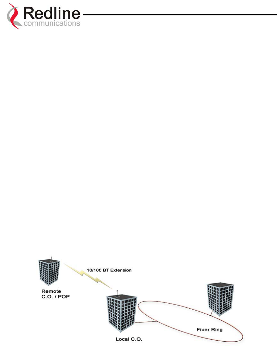
AN-30 System User Manual
1
10
0.
.
B
Br
ro
oa
ad
db
ba
an
nd
d
F
Fi
ix
xe
ed
d
W
Wi
ir
re
el
le
es
ss
s
P
Pr
ri
im
me
er
r
This section provides an overview of the design and benefits of Broadband Fixed
Wireless (BFW) network architecture based on the Redline AN-30 System.
10.1. Who Can Benefit From The AN-30 System?
The AN-30 system is an ideal solution for:
• Carriers
• Internet Service Providers (ISPs)
• Enterprises
• Educational Institutions and Campuses
A) Carriers
The AN-30 system will provide benefits to both Incumbent and Competitive Local
Exchange Carriers (ILECs and CLECs, respectively). Although ILECs own and provide
services over wireline infrastructures within a specific geographical area, they are faced
with the challenges of reaching outlying regions suffering from poor to no service. The
ILEC is usually compelled to provide an expensive solution using a series of PTP radio
links, with low throughput (e.g., T1) and costly license fees and network interfaces
including T1 multiplexers. The AN-30 system provides a cost-effective alternative, by
connecting a remote site from the local CO, as shown in see Figure 17.
Figure 17: Wireless Extension for Carriers
The same challenges are faced by CLECs, who can use the AN-30 system to:
• Extend their existing fiber network, and
• Establish a remote Point of Presence (POP).
Mobility carriers will benefit from the AN-30 to provide a cost-effective alternative to
landline T1/E1 carrier leased circuits. In most cases, equipment payback is achieved in 6-
Page 62 of 80
Redline Communications …..solving the first mile challenge
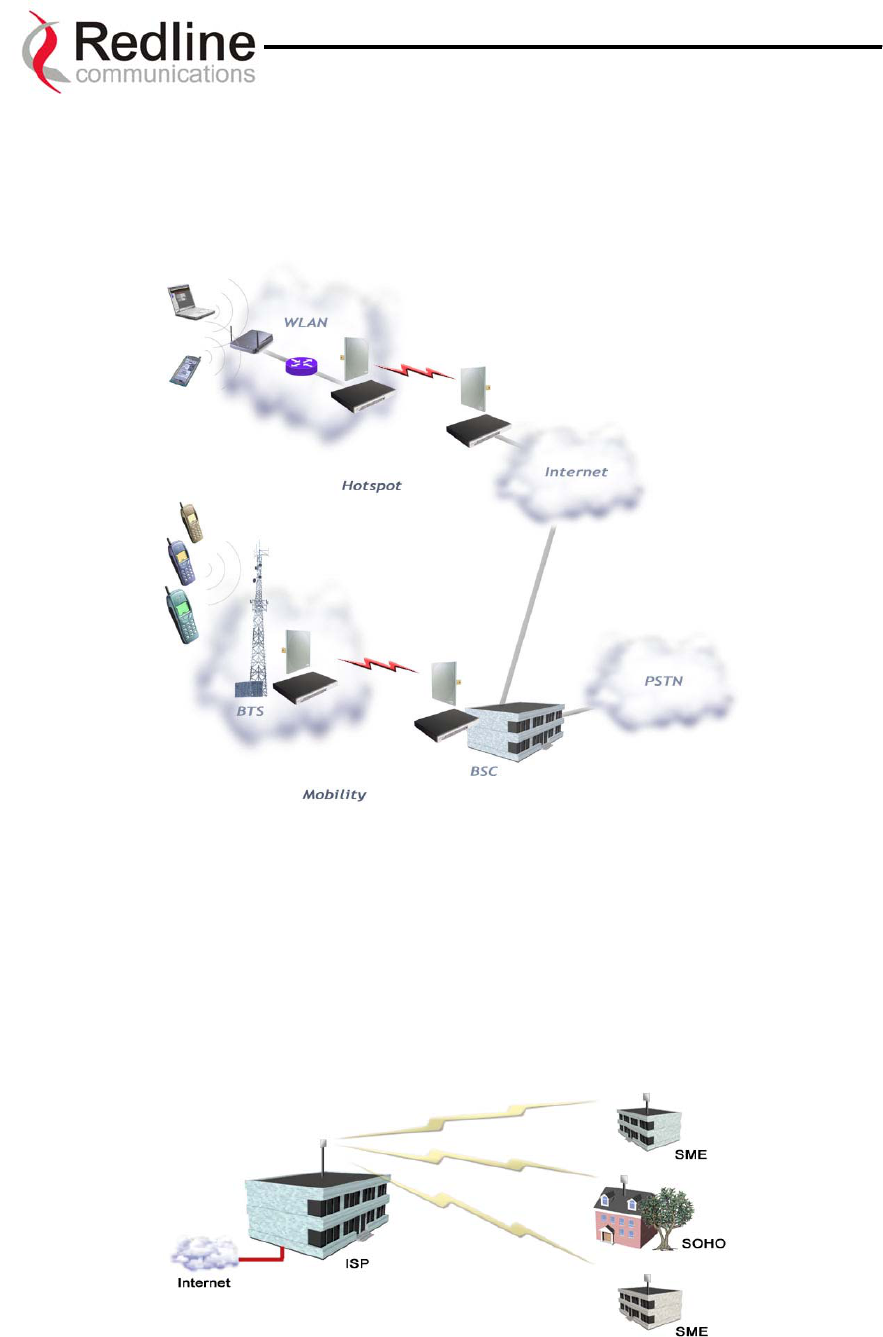
AN-30 System User Manual
12 months. In addition to backhauling voice, mobility carriers can support converged
networks, backhauling voice with data, to derive incremental revenue from existing BTS
infrastructures. An example is given in the figure below, where voice and data from hot-
spots are backhauled from the same AN-30 node.
B) Internet Service Providers
The AN-30 system is perfect for ISPs looking to provide cost-effective broadband
solutions to demanding business customers including Small Office Home Office (SOHO)
and Small to Medium sized Enterprises (SME) located just outside of the downtown core,
where there is a lack of infrastructure. High-speed leased lines are expensive and hard to
obtain, especially from local telephone companies. Wireless access provides a reliable
quality of service over longer distances, while avoiding Telco access fees.
Figure 18: Wireless Solution For ISPs
Page 63 of 80
Redline Communications …..solving the first mile challenge
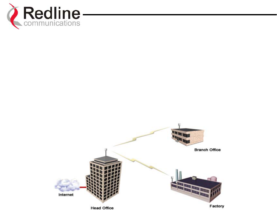
AN-30 System User Manual
C) Enterprises
Enterprises are particularly frustrated by the lack of broadband connectivity to branch
offices, factories, or warehouses located just outside of the urban core. Establishing a
LAN solution over several remote locations presents a significant inter-network challenge
using conventional wireline solutions. The AN-30 system is well suited for addressing
LAN extension requirements, offering superior data rates and PBX voice/ voice over IP
(VoIP) connectivity in a secure format using encryption to protect sensitive information.
Figure 19: Wireless Solution For Enterprise
D) Educational Institutions and Campuses
The World Wide Web is a key element within the education system today, with BFW
systems serving as an important enabler in bringing Internet content to the student body.
Fixed wireless systems such as the AN-30 provide a cost effective means of creating a
backbone for connecting existing and new campus buildings to the educational
infrastructure to support distance learning and two-way interactive training.
10.2. The AN-30 Advantage
The Redline AN-30 system includes several key features to mitigate the effects of
interference arising from other systems operating co-channel in the vicinity, as well as
coping with propagation anomalies such as multipath. These features include:
Up to 64QAM Modulation
The modulation schemes supported are:
• Binary Phase Shift Keying (BPSK)
• Quadrature Phase Shift Keying (QPSK)
• 16 Quadrature Amplitude Modulation (QAM)
Page 64 of 80
Redline Communications …..solving the first mile challenge

AN-30 System User Manual
• 64 QAM
Refer to Table 8 for a summary of data rates for each modulation scheme.
Advanced Error Correction
In addition to conventional forward error correction techniques, the AN-30 terminal uses
an Automatic Repeat Request (ARQ) scheme to dramatically reduce errors from
interference and multipath
Orthogonal Frequency Division Multiplex (OFDM) Processing
The Redline OFDM technique offers tremendous robustness in the presence of harsh
multipath interference.
Narrow Beam Width
Narrow antenna beams reduce considerably the probability of interference entering the
system.
In addition to the anti-interference features described above, the AN-30 system also holds
several other competitive advantages:
• High Data Rates
• High Bandwidth Efficiency
• Long Reach and Wide Coverage
• Higher Power Efficiency
• "Over-the-Air" Security
Support For TDM Applications
By supporting 802.1p and 802.3x protocols, the AN-30 can reliably maintain 4 T1/E1
native ports as well as up to eight T1/E1 lines using third party units. For more
information regarding TDM application support, see Appendix 4 on page 76.
Page 65 of 80
Redline Communications …..solving the first mile challenge

AN-30 System User Manual
10.3. Wireless Facts
Wireless technology has existed for many years, proving itself to be a reliable
communication medium, primarily for long haul point-to-point applications supporting
critical links across the country for telephony and broadcast services. With the surge of
broadband two-way internet use, fixed wireless systems are playing an even more
important role in supporting network infrastructures.
The AN-30 system has been designed to operate in the band, which occupies the license
exempt portion of the spectrum. This allows an operator to set up a wireless network
without requiring formal consent from the regulatory agent. While this provides great
advantages in terms of cost and time to market, the ease of access to the spectrum can
bring with it undesirable effects, such as potential interference arising from other users
exploiting the "free" band. By following the simple deployment guidelines in this
manual, issues of this nature can be avoided.
This section provides additional background material to section 6 of this manual,
including a description of the Link Budget tool, Fresnel zone considerations, height
calculations, interference issues and radar horizon considerations.
10.3.1. The Link Budget Tool
Redline has developed a Link Budget Tool to help characterize the range performance of
the AN-30 system for LOS, OLOS (optical line of sight) and NLOS conditions and
various system parameters. The Link Budget Tool can be obtained by contacting your
Redline certified partner or system integrator. Note the tool provides a first-order
approximation, and does not consider the details of any specific terrain profile which may
impact performance; rather, a generalized terrain is used in the calculations, based on
empirical formulas approved by governing bodies such as the IEEE and ITU. Also, the
tool does not consider system parameter variations arising from temperature fluctuations,
cable loss tolerance, antenna alignment errors, etc.
The Link Budget Tool estimates the distance over which the system can operate at a
desired error rate while achieving robust communication. A link is considered robust if
the average error rate is less than 1 bit out of every 1000 million, expressed as 10-9, for an
availability of 99.99%. Availability is described in more detail below.
The table below describes the net data rate (after coding overhead) that can be obtained
for each modulation type in an ideal propagation situation.
Page 66 of 80
Redline Communications …..solving the first mile challenge

AN-30 System User Manual
Table 8: Modulation Scheme vs. Data Rate
Modulation
Coding
Rate
Over The
Air Rate
(Mbps)
Uncoded
Burst Rate
(Mbps)
Average
Ethernet Rate
(Mbps)
BPSK ½ 12 6 5.82
BPSK ¾ 12 9 8.63
QPSK ½ 24 12 11.38
QPSK ¾ 24 18 16.7
16 QAM ½ 48 24 21.77
16 QAM ¾ 48 36 33.01
64 QAM ⅔ 72 48 44.1
64 QAM ¾ 72 54 48.8
As indicated in the table above, higher order modulation schemes require greater S/N to
maintain the same BER performance. The noise in this case is defined as the noise floor
of the receiver, i.e., it assumes no interference from other sources (interference from
other sources are addressed below). The main path calculation for determining range
performance is given as:
RSL = Ptx + Gtx – FSL + Grx
Where:
Ptx is the transmit power level in dBm
Gtx is the transmit antenna gain in dB
FSL is the free space loss attenuation in dB, and
Grx is the receive antenna gain in dB
The FSL value is dependent on the range between the two terminals, the type of terrain
over which the link is deployed, and whether or not the link is operating line of sight
(LOS), optical line of sight (OLOS) or non-LOS (NLOS). The LOS FSL calculation is
well understood and easy to calculate, and relies on the fact there is absolutely no
obstacle near the direct path. The precise method for determining the amount of clearance
required for LOS involves making use of a factor known as the Fresnel zone. A Fresnel
zone is defined as a path difference of λ/2 away from the direct path, as shown in Figure
20. A "cleared LOS" link assumes there are no obstacles within 60% of the first Fresnel
zone of the direct path. The diagram below illustrates OLOS conditions, where a treetop
is within the first Fresnel zone, and a clear direct path exists between the antennas.
Page 67 of 80
Redline Communications …..solving the first mile challenge
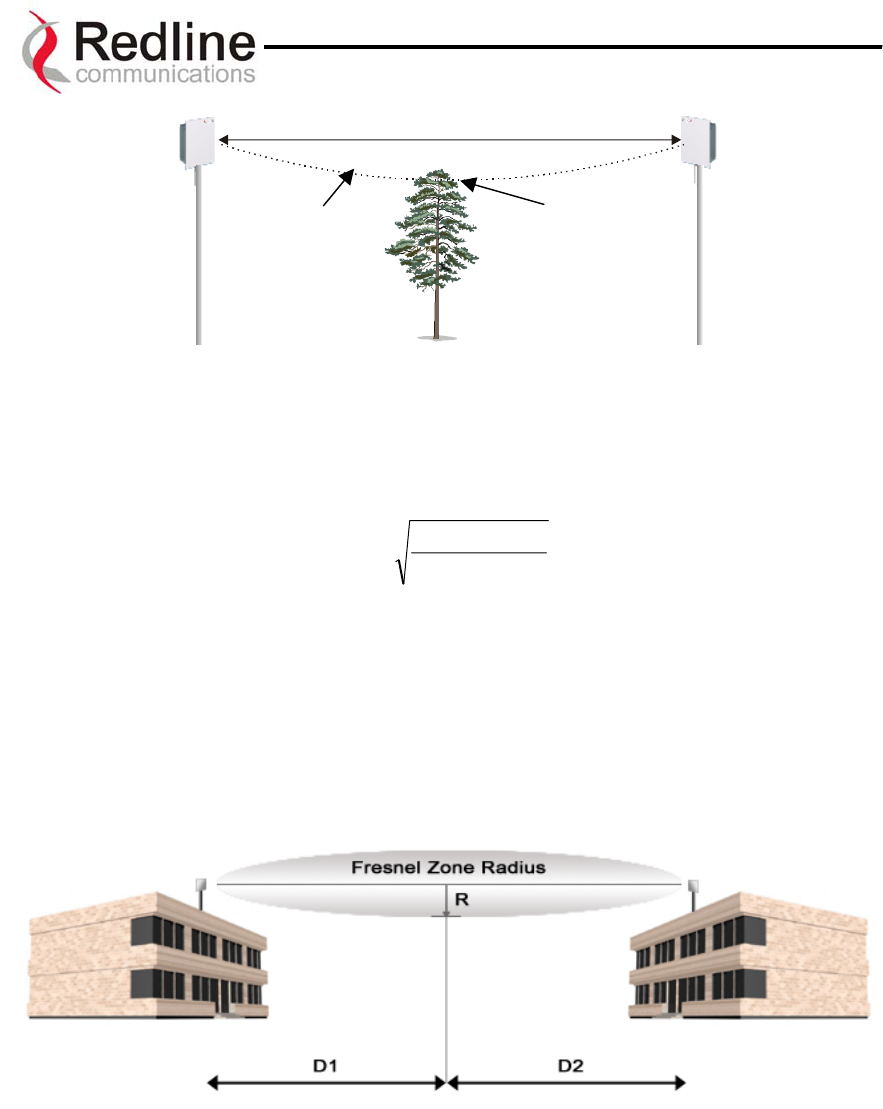
AN-30 System User Manual
First
Fresnel
Zone
Obstruction within
first Fresnel Zone
Figure 20: Fresnel Zone Obstruction
The formula for calculating the radius of the first Fresnel zone, as depicted in Figure 21,
is given as:
)21(*
2*1
1.72 DDf
DD
R+
= (ft)
where,
- D1 and D2 are the distances from the terminals to the point of interest (in
miles), and
- f is the frequency (in GHz)
(Note: multiply results by 0.3048 to obtain a solution in meters)
Figure 21: Fresnel Zone Radius Calculation
Specific FSL formulas are required to deal with this NLOS phenomenon. There are many
NLOS calculations available from established institutions including the Institute of
Electrical and Electronics Engineers (IEEE) and International Telecommunications
Union (ITU), who are chartered with developing standardized calculations. The Redline
Link Budget Tool is built upon these formulas; however, it is important to bear in mind
that the calculations are an estimate only, with relatively large standard deviations (5-15
dB) depending on the exact deployment scenario and obstacle characteristics.
Page 68 of 80
Redline Communications …..solving the first mile challenge

AN-30 System User Manual
The last element to consider in the path calculation is the signal to noise (S/N) ratio,
which is defined as:
S/N = RSL – Smin
where,
Smin is the receiver sensitivity expressed in dBm.
The Smin is determined by the thermal noise generated by the amplifier as well as the
bandwidth of the filter used in the receiver front end. It defines the power level at which
the receiver is sensitive enough to properly detect the signal. For the AN-30 operating in
a channel spacing of 20 MHz, the Smin is approximately –96 dBm.
To ensure the link is sufficiently robust to deal with unexpected attenuation effects and
seasonal fades, the S/N must be set higher than the S/Nmin specific to each modulation
level. The difference between these two levels is called the Fade Margin (FM). FM is
similar to a "power reserve", in which extra power is designed into the link budget to deal
with additional fades arising from such factors as climatic conditions (seasonal),
multipath dispersions, and shadowing effects from natural (foliage) and man-made
obstacles (buildings). The FM is determined by the availability one desires. Availability
is defined as the amount of time (expressed in % per year) that a link properly detects the
signal. "Properly” in this case is a BER that is less than 10-9. The table below describes
the outage period per year that corresponds to the different availability values.
Table 9: Availability Versus Outage Time
Availability (%) Outage Period Per Year
99.9 8.8 hours
99.99 53 minutes
99.999 5.3 minutes
99.9999 32 seconds
It is recommended that the link be designed for an availability of greater than 99.99%.
The tool automatically calculates the estimated required fade margin over distance to
achieve this availability.
A key advantage of the AN-30 product is that it features a transmission correction
scheme called Automatic Repeat Request (ARQ). The ARQ algorithm essentially detects
when a packet(s) has been lost, due to fading, and makes a request to the remote system
to re-transmit the lost packet(s). This feature provides an equivalent link budget gain of
over 5 dB, which translates directly to an improved margin.
Another advantage of the AN-30 is its supports of multiple modulation schemes, i.e.,
BPSK, QPSK, 16QAM, and 64QAM. The system allows separate selection of the
Page 69 of 80
Redline Communications …..solving the first mile challenge
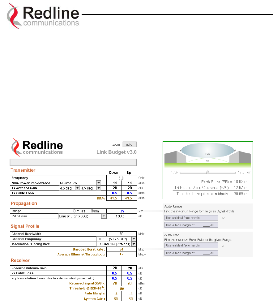
AN-30 System User Manual
modulation scheme for uplink and downlink. In this manner, the network can be balanced
for the optimum spectral efficiency, no matter what propagation conditions prevail.
Higher order modulation schemes (i.e., 64 QAM) are typically deployed at reduced
ranges while lower order modulation schemes (i.e., BPSK) are implemented at long
distances.
A sample link budget is shown in Figure 22 for the AN-30 system operating in 64 QAM,
3/4 code rating, providing a net burst throughput of 54 Megabits per second (Mbps). This
provides an average throughput of 43 Mbps to the Ethernet port. The calculation is
performed for LOS, however the graph (shown in Figure 23 below) also covers the
OLOS and NLOS conditions.
Figure 22: Link Budget For 64 QAM ¾ Code Rate
A fade margin graph for this link budget is given in Figure 23 below for four conditions:
LOS (a - blue line), OLOS with the first Fresnel zone obstructed (b - red line), NLOS
scattered trees and buildings (c - green line) and heavily treed residential NLOS (d -
magenta line).
Page 70 of 80
Redline Communications …..solving the first mile challenge
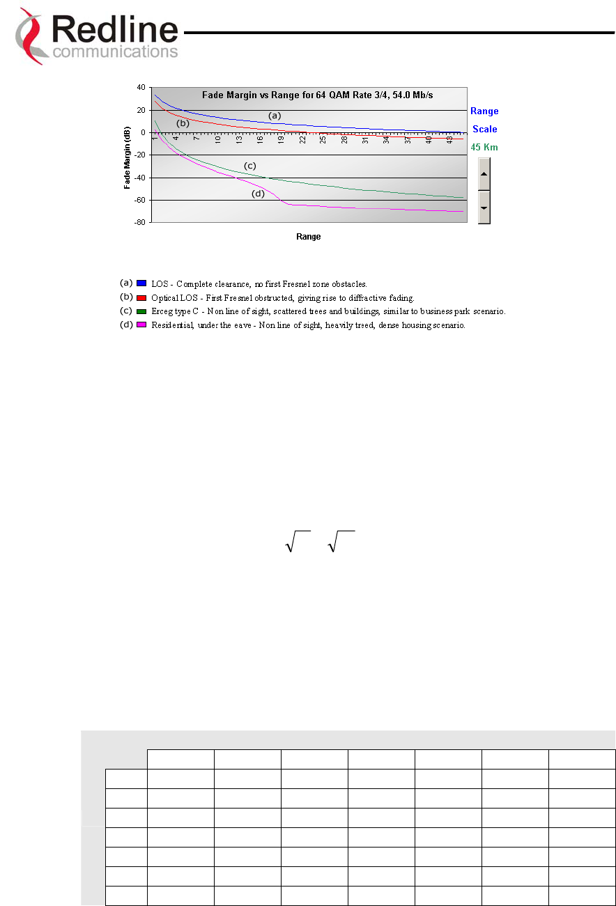
AN-30 System User Manual
Figure 23: Fade Margin Graphs For LOS, OLOS and NLOS
The graph assumes a fade margin of 3 dB. The effects of rain at bands are negligible,
hence are not included in the link budget.
It is important to note the link calculation assumes that the Earth’s curvature is not
blocking the propagation path. The equation for determining the distance at which the
Earth will cause blockage is called the Radar Horizon, and is given as follows:
Rh=)(1.4 21 hh + (km)
where,
h1 is the height of terminal 1 (m)
h2 is the height of terminal 2 (m)
The table below specifies the horizon distance (km) that can be achieved for different
terminal heights ranging from 10 to 70 m above mean terrain level.
Table 10: Radar Horizon Ranges For Different Terminal Heights (H1 and H2)
H2
10 20 30 40 50 60 70
10 25.9 31.3 35.4 38.9 42.0 44.7 47.3
20 31.3 36.7 40.8 44.3 47.3 50.1 52.6
30 35.4 40.8 44.9 48.4 51.4 54.2 56.8
40 38.9 44.3 48.4 51.9 54.9 57.7 60.2
50 42.0 47.3 51.4 54.9 58.0 60.7 63.3
60 44.7 50.1 54.2 57.7 60.7 63.5 66.1
H1
70 47.3 52.6 56.8 60.2 63.3 66.1 68.6
Page 71 of 80
Redline Communications …..solving the first mile challenge
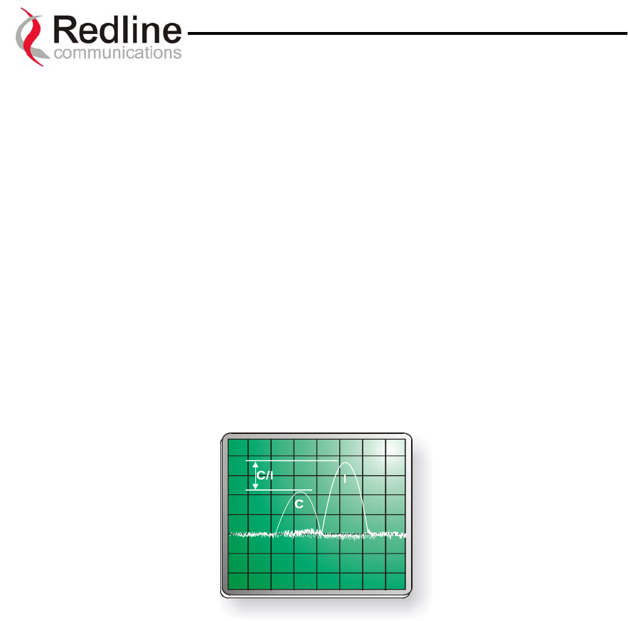
AN-30 System User Manual
10.4. Deployment Scenarios
This section examines two types of deployment scenarios: co-located (same rooftop), and
adjacent area.
10.4.1. Co-located Deployments
It is possible to deploy more than one AN-30 system from the same rooftop to support
multiple links, however, it is important to consider issues that may arise from co-channel
and adjacent channel interference.
Co-channel interference results when two systems operate simultaneously in the same
channel. This must be avoided by selecting different channels in the AN-30
Configuration screen. Adjacent channels are acceptable; however, it is important that the
adjacent channel does not exceed the acceptable channel-to-interference (C/I) ratio for
the system, as shown in Figure 24 (C is the desired channel, while I is the interferer).
Frequency (Mhz)
Power (dB)
Figure 24: Adjacent Channel Interference.
10.4.2. Adjacent Area Deployments
During the installation process, it is important to ensure there is no potential for
interference from other systems deployed in adjacent areas. Figure 25 presents a simple
deployment configuration to illustrate the potential interference that may arise from
adjacent area sources (Users 1 to 4 in Figure 25).
The desired communication link is between Terminals 1 and 2. The link between Users 1
and 2 must operate in an adjacent channel to avoid interference with the desired link.
Users 3 and 4, on the other hand, can operate co-channel since they are outside the
narrow beam width of both terminals. Narrow beam widths are one feature of the AN-30
to help address potential interference.
Page 72 of 80
Redline Communications …..solving the first mile challenge
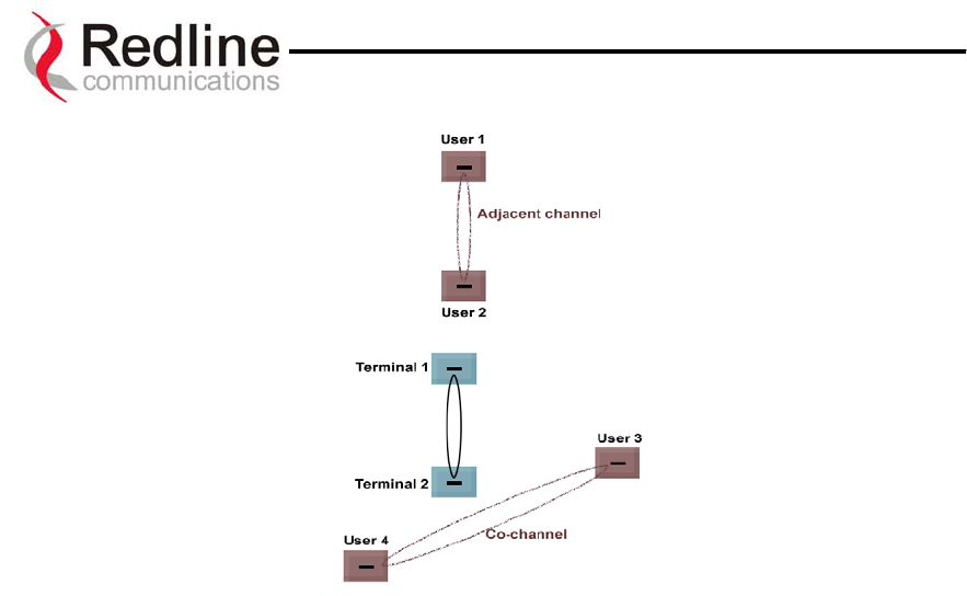
AN-30 System User Manual
Figure 25: Deployment Scenarios
Page 73 of 80
Redline Communications …..solving the first mile challenge

AN-30 System User Manual
1
11
1.
.
A
Ap
pp
pe
en
nd
di
ix
x
11.1. Appendix 1 - Glossary Of Terms
AN-30 Redline Communications’ Access Node-50 Broadband Fixed
Wireless (BFW) system.
Antenna A device for transmitting and/or receiving a radio frequency (RF).
Antennas vary in design and frequencies supported.
Antenna Gain The measure of antenna performance relative to a theoretical antenna
called an isotropic antenna.
ARQ Automatic Repeat Request. This is the protocol used over the air for
error correction.
Beamwidth The angle of signal coverage provided by an antenna.
BFW Broadband Fixed Wireless
Bps (Bits Per Second) A unit of measurement for the rate at which data is transmitted.
BPSK Binary Phase Shift Keying.
Channel A communications path wide enough to permit a single RF
transmission.
dB A ratio expressed in decibels.
dBi A ratio, measured in decibels, of the effective gain of an antenna
compared to an isotropic antenna.
dBm Decibels above a milliwatt
DHCP Dynamic Host Configuration Protocol. A DHCP server will
automatically issue IP addresses within a specified range to devices
on a network.
Directional Antenna An antenna that concentrates transmission power into one direction.
Encryption For the purposes of privacy, the transformation of data into an
unreadable format until reformatted with a decryption key.
Ethernet A LAN architecture using a bus or star topology
FD Full Duplex. Refers to the transmission of data in two directions
simultaneously (i.e. a telephone)
FWA Fixed Wireless Access
Gain The ratio of the output amplitude of a signal to the input amplitude of
a signal. Typically expressed in decibels (dB).
Gateway A network point that acts as an entrance to another network.
GHz Gigahertz. 1,000,000,000 Hz, or 1,000 MHz
GUI Graphical User Interface
Hertz (Hz) The international unit for measuring frequency, equivalent to the
number of cycles per second. One megahertz (MHz) is one million
Hertz. One gigahertz (GHz) is one billion Hertz.
IF Intermediate Frequency.
IP (Internet Protocol) See TCP/IP.
Isotropic A theoretic construct of an antenna that radiates its signal 360 degrees
both vertically and horizontally—a perfect sphere. Generally used as
a reference.
IXC (Inter-exchange Carrier) A long-distance phone company.
LAN (Local Area Network) A data communications network, typically within a building or
campus linking computers, printers and other devices together.
LEC (Local Exchange Carriers) The traditional local wired phone company.
LED Light Emitting Diode
LOS Line Of Sight. A clear direct path between two antennas, with no
obstructions within the first Fresnel zone.
MAC (Media Access Control) A uni
q
ue number assi
g
ned to a network device. It corres
p
onds to the
Page 74 of 80
Redline Communications …..solving the first mile challenge

AN-30 System User Manual
ISO Network Model Layer 2 data link layer.
MHz Megahertz. 1,000,000 Hz
Modem
(MOdulator/DEModulator)
A hardware device which converts digital data into analog and vice
versa.
Modulation Any of several techniques for combining user information with a
transmitter carrier signal.
Multipath The radio echoes created as a radio signal bounces off of objects.
NLOS Non Line Of Sight. Completely obstructed path between two
antennas.
OFDM Orthogonal Frequency Division Multiplexing. OFDM spreads data to
be transmitted over a large number of orthogonal carriers.
OLOS Optical Line Of Sight. A clear direct path between two antennas, with
obstructions within the first Fresnel zone.
Packet A bundle of data organized in a specific way for transmission. The
three principal elements of a packet include the header, the text, and
the trailer (error detection and correction bits).
PHY (Physical Layer) Provides for the transmission of data through a communications
channel by defining the electrical, mechanical, and procedural
specifications.
PTP Point to Point
QAM Quadrature Amplitude Modulation
QPSK Quadrature Phase Shift Keying
Receiver Sensitivity A measurement of the weakest signal a receiver can receive and still
correctly translate it into data.
RF Radio Frequency
Rx Receiver
S/N Signal to Noise Ratio
SINADR Signal to noise and distortion ratio.
TCP/IP (Transmission Control
Protocol/Internet Protocol)
The standard set of protocols used by the Internet for transferring
information between computers, handsets, and other devices.
TFTP Trivial File Transfer Protocol
Tx Transmitter
Page 75 of 80
Redline Communications …..solving the first mile challenge

AN-30 System User Manual
11.2. Appendix 2 – AN-30 Support For TDM explained
802.1p QoS
The AN-30 uses IEEE 802.1p to ensure QoS to TDM based applications such as mobility
backhaul and enterprise PBX traffic. IEEE 802.1p allows traffic to be assigned into one
of two (high or low priority) queues. Ethernet packets are queried to determine if they
are priority tagged. Packets tagged with a priority value greater than or equal to four are
automatically placed in the high priority queue. All other packets go into a default queue.
The AN-30 always services the traffic in its high priority queue before the default, lower
priority queue. A low priority packet will only be transmitted once the high priority
queue is empty.
Flow Control
The AN-30 uses standard IEEE 802.3x flow control, for improved traffic handling.
IEEE 802.3x defines a control protocol between interfacing Ethernet port for the purpose
of pausing transmission from an upstream device. Upon reception of a pause control
frame, an Ethernet port will not transmit it’s next normal data frame until the timer
specified in the pause control frame expires, or another pause control frame is received
with it’s timer set to zero. During the flow controlled period, only flow control packets
can be transmitted between across the Ethernet link.
The AN-30 uses this mechanism internally transmitting pause control frames as required
based on the availability of its own internal resources, including buffers, transmit queues
and receive queues.
Since Ethernet traffic typically runs at 100 Mbps it can easily exceed the maximum
capacity of the wireless link. Left unchecked this situation will trigger indiscriminate
packet discarding in the wireless transmit buffer. To avoid this condition the AN-30’s
wireless interface issues pause control frames to flow control upstream traffic. This
effectively provides an automatic traffic shaping capability that automatically triggers in
advance of a buffer overflow condition occurring. The system will therefore adjust itself
to the available wireless throughput. If wireless throughput is decreased the system will
automatically throttle-back (traffic shape) the lower priority traffic streams by first
discarding the packets in its default queue.
Upon receiving additional packets, the system will issue pause control frames to halt
upstream transmission until it can service its wireless transmit buffers.
Once wireless resources are again freed up, a new pause control frame is issued to resume
transmission.
Page 76 of 80
Redline Communications …..solving the first mile challenge

AN-30 System User Manual
11.3. Appendix 3 - AN-30 System Specifications
AN-30 System Specifications
System Capability PTP mode, OFDM technology for robustness
RF Band 5.725 - 5.825 GHz
Channel 1 1A 2 2A 3 3A 4 4A 5
Channel Center
Frequencies Freq. 5.735
GHz
5.745
GHz
5.755
MHz
5.765
GHz
5.775
GHz
5.785
GHz
5.795
GHz
5.805
GHz
5.815
GHz
Channel Size 20 MHz
RF Dynamic Range > 50 dB
Modulation Coding Rate Over The Air
Rate (Mbps)
Uncoded
Burst Rate
(Mbps)
Average TDM
+ Ethernet
Rate (Mbps)
BPSK ½ 12 6 5.82
BPSK ¾ 12 9 8.63
QPSK ½ 24 12 11.38
QPSK ¾ 24 18 16.7
16 QAM ½ 48 24 21.77
16 QAM ¾ 48 36 33.01
64 QAM ⅔ 72 48 44.1
Modulation/Throughput
64 QAM ¾ 72 54 48.8
Maximum Tx Power -20 to +20 dBm (channel dependent and region specific) *
Rx Sensitivity -86 dBm at 6 Mbps (based on BER of 1x10⁻⁹)
IF Cable • Maximum length up to 250 ft (76m) using RG6U / 500 ft (152m) using
high-grade RG11U
• Maximum allowable losses at 2.5 GHz:
RG6: 10 dB/30m (100 feet) at 250C
RG11: 5 dB/30m (100 feet) at 250C
• Multiplexed IF, DC power, control (Tx/Rx, AGC, APC)
Network Attributes • Transparent bridge
• DHCP passthrough
• VLAN passthrough
• 802.3x Ethernet flow control
• 802.1p Network traffic prioritization
Modulation Modulation Options (bi-directional):
• BPSK • QPSK • 16 QAM • 64 QAM
Over The Air
Encryption
Proprietary 64-bit encryption
Coding Rates 1/2, 3/4 and 2/3
MAC • Point to point
• Automatic Repeat Request (ARQ) error correction
• Concatenation
Range • Over 10 km / 6 miles for non-line-of-sight
• Over 80 km / 50 miles line-of-sight @ Tx 20 dBm
Network Services Transparent to 802.3 services and applications
Duplex Technique Dynamic TDD (time division duplex)
Wireless Transmission OFDM (orthogonal frequency division multiplexing)
Backhaul Connection 10/100 Ethernet (RJ45)
System Configuration • SNMP
• CLI via Telnet and Local Console Port
* Note: In some countries outside of North America, the Max. Operational Power Per Channel with a given antenna is
limited in accordance to maximum allowable EIRP levels for the region.
Page 77 of 80
Redline Communications …..solving the first mile challenge

AN-30 System User Manual
AN-30 System Specifications continued….
TDM Specifications
Performance
Jitter Buffering 5 to 300 msec
Line Length 2000m using 22 AWG twisted pair cable
Line Build-out 0dB, -7.5dB, -15dB, –22.5dB
Remote loop and local loop testing Diagnostics
Detects and Generates LOS (red), AIS (blue), RAI (yellow)
1 to 4 T1/E1 TDM Ports, Supports Fractional nx64 Services Interface Ports
1 RJ-45 (10/100BaseTX with Optional High Speed Data Upgrades)
E1 Specs T1 Specs
Standards ETS TBR 12/13, ITU-T Rec.
G.703, G.704, G.706, G.732,
G.821, G.823, G.826
AT&T TR-62411, ANSI T1.403,
ITU-T Rec. G.703, G.704, G.733,
G.821, G.824, G.826
Framing Unframed, CRC4, FAS/MFAS Unframed, D4 (SF), ESF
Data Rate 2.048 Mbps 1.544 Mbps
Line Code HDB3, AMI AMI, B8ZS
Connector RJ-48c, BNC Balanced RJ-48c, 8 pin
Line Impedance Balanced: 120 Ohm (RJ-48c)
Unbalanced: 75 Ohm (BNC)
Balanced 100 Ohm
Jitter ITU-T G.823 Per AT&T TR-62411, ITU-T G.824
Clocking Adaptive, Loopback, Internal Adaptive, Loopback, Internal
Line Protection ITU-T K-20, K-21 Bell Core GR 1089
AN-30 Physical Specifications
Power Requirements Single / Dual 110/220/240 VAC (auto-sensing) 50/60 Hz, 39W
maximum
Single / Dual 48 VDC, 39W maximum
Operating
Temperature Range
AN-50 Terminal Operating Conditions: 41F to 104F / 5C to 40C
AN-50 Terminal Short-Term Conditions: 23F to 41F and 104F to
131F / -5C to 5C and 40C to 55C for up to 16 hours
T-58 Operating Conditions: -40F to +140F / -40C to +60C
Wind Loading AN-30 Radio: 137 mph / 220 km/hr
Physical Configuration AN-30 terminal, AN-30 Radio
AN-30 Dimensions 17” x 12” x 1.75” / 431.8 mm x 304.8 mm x 44.45 mm
Component Weights AN-50 Terminal ……………………………………. 2.0 kg
T-58 Transceiver …………………………………… 1.0 kg
Vertical Mast Bracket Kit ………………….……… 3.0 kg
Vertical Mast Bracket Hardware Kit ……………… 0.5 kg
Cable, F Male/F Male, RG6, 100 ft 1.3 kg
A
ntenna……………..…………………………….… 1.0 to 16.0 kg
Page 78 of 80
Redline Communications …..solving the first mile challenge

AN-30 System User Manual
MTI part No. MT-485002
Page 79 of 80
Redline Communications …..solving the first mile challenge

AN-30 System User Manual
Page 80 of 80
Redline Communications …..solving the first mile challenge
302 Town Centre Blvd. • Markham, Ontario • Canada • L3R 08E
www.redlinecommunications.com