Redline Communications AN5030EX AN-50e/AN-30e System w/ T-58e Radio User Manual 70 00035 01
Redline Communications Inc. AN-50e/AN-30e System w/ T-58e Radio 70 00035 01
UserManual.wiki
>
Redline Communications
>
AN5030EX User Manual
>
USERS MANUAL 1
Contents
1.
USERS MANUAL 1
2.
USERS MANUAL 2
USERS MANUAL 1
Navigation menu
Upload a User Manual
Namespaces
Wiki Guide
HTML
PDF
Info
Views
User Manual
Discussion / Help
Navigation
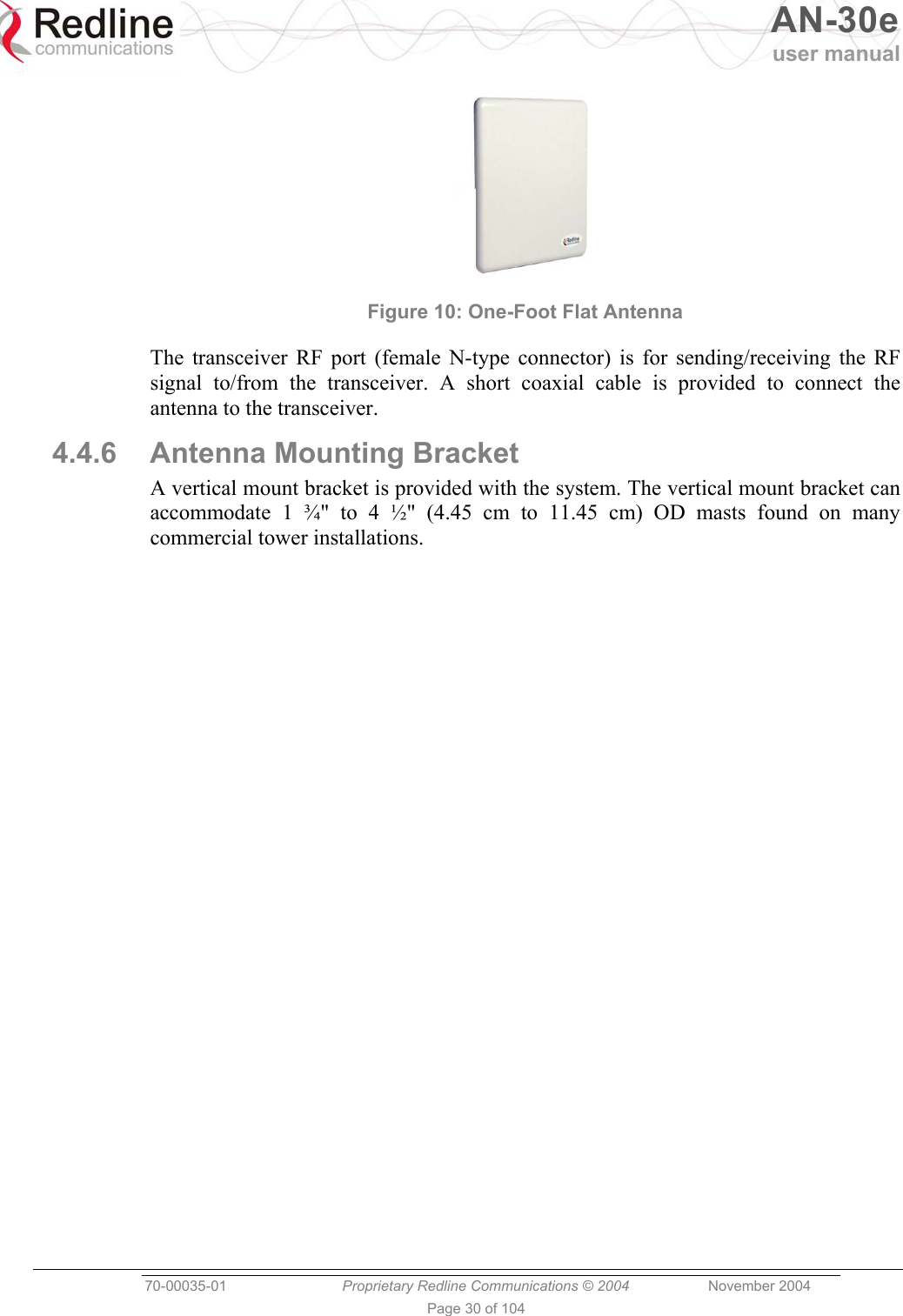
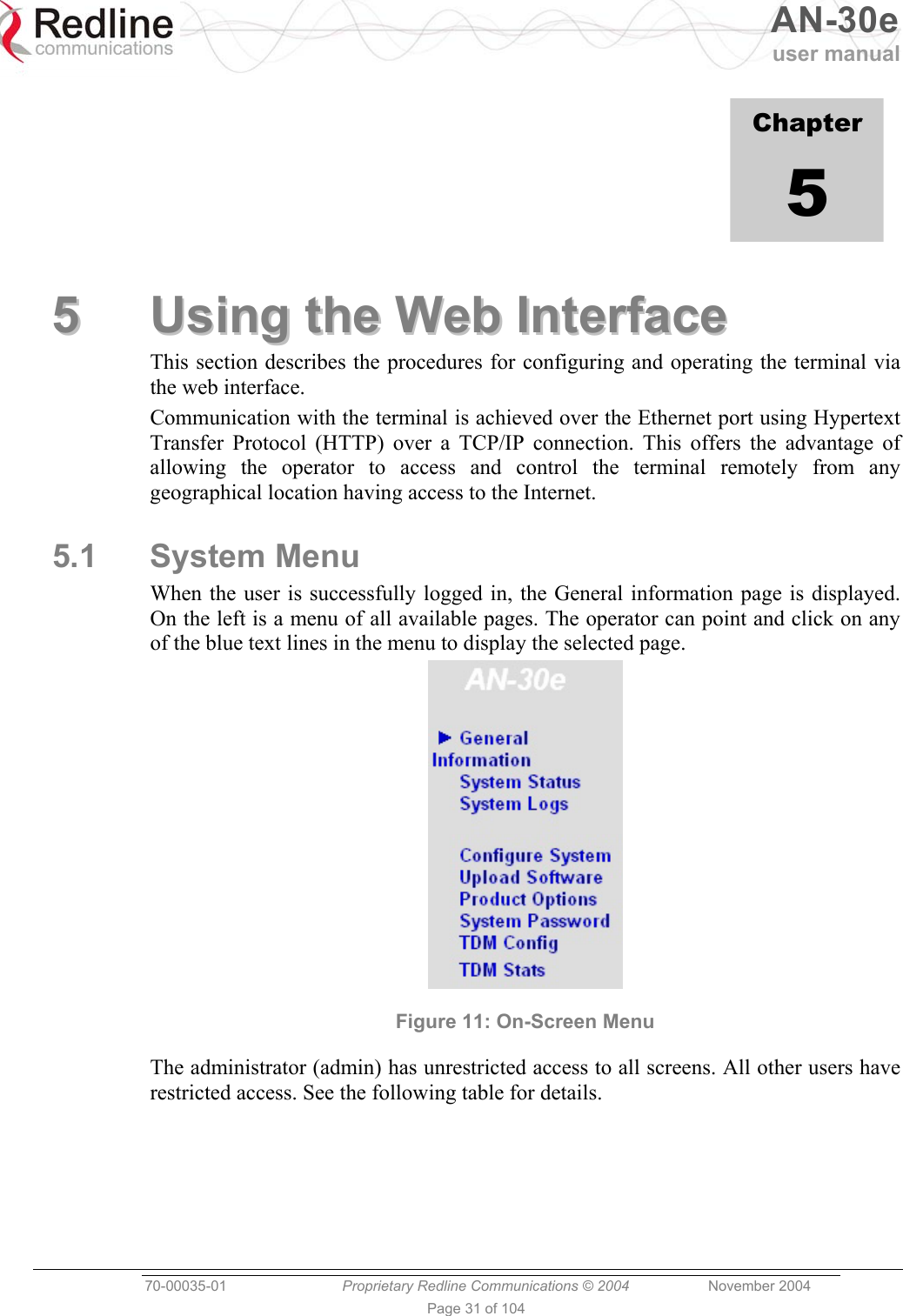
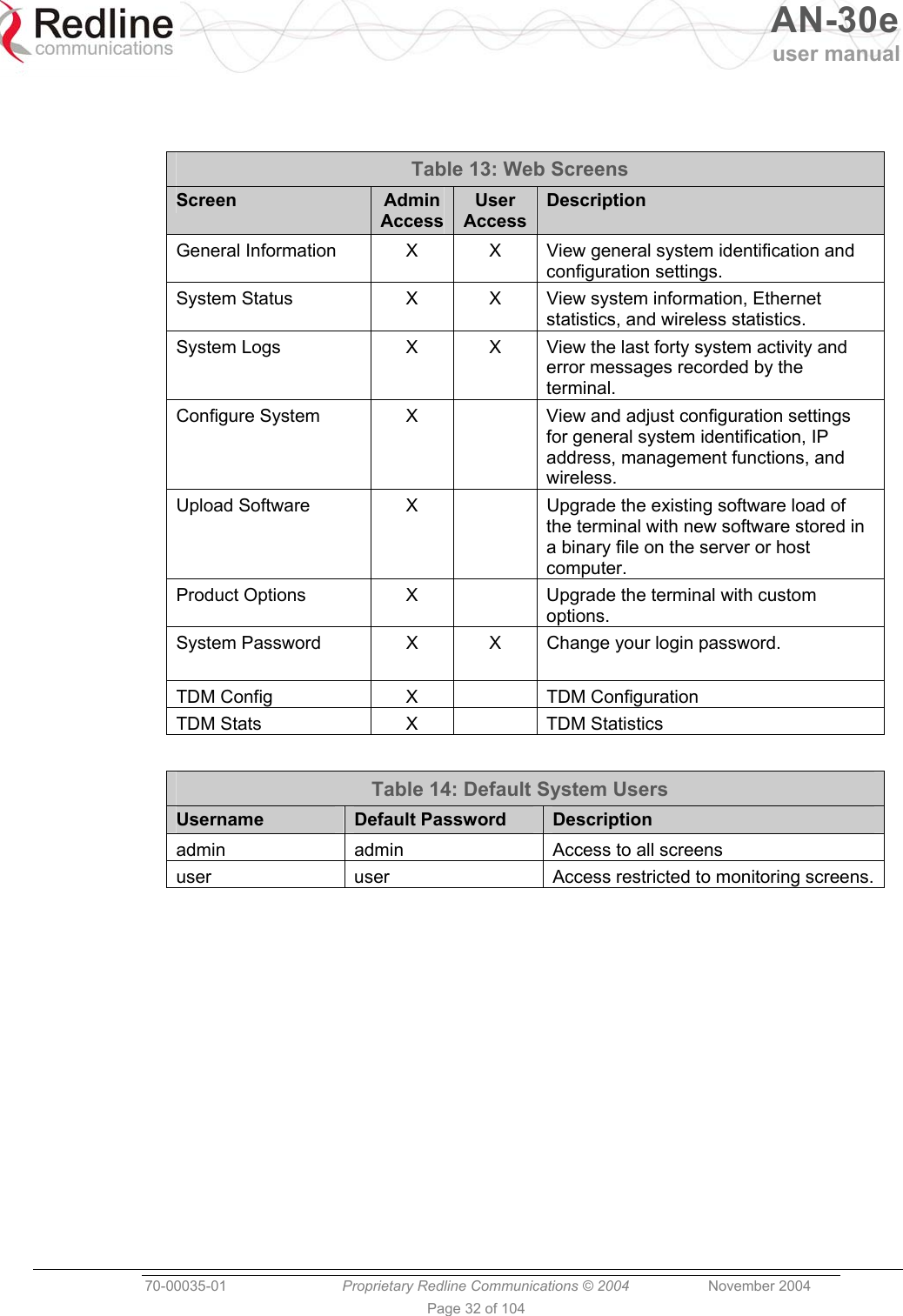
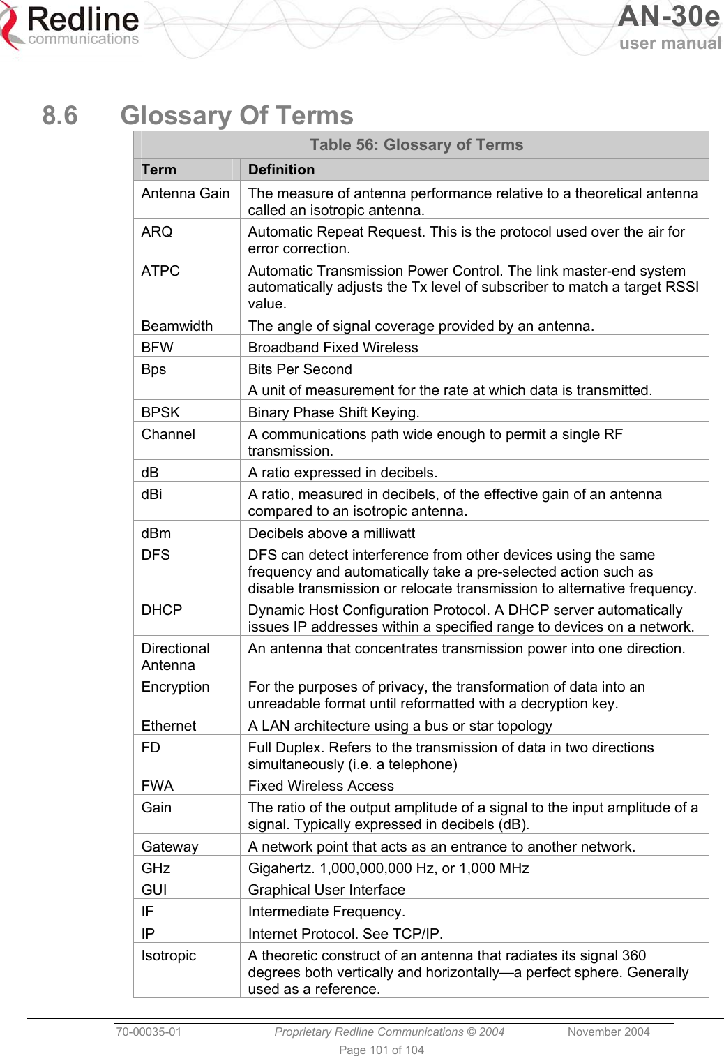
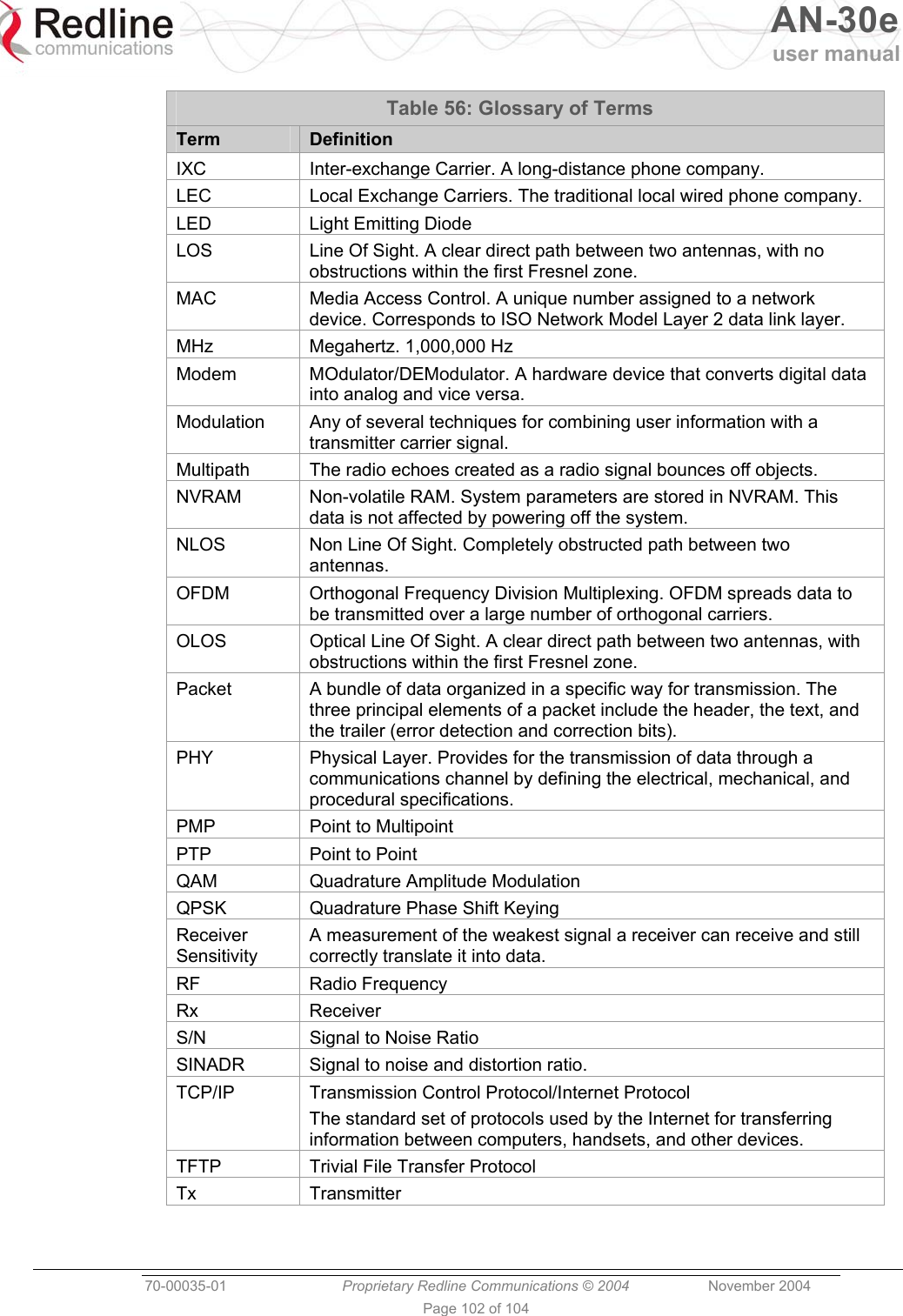
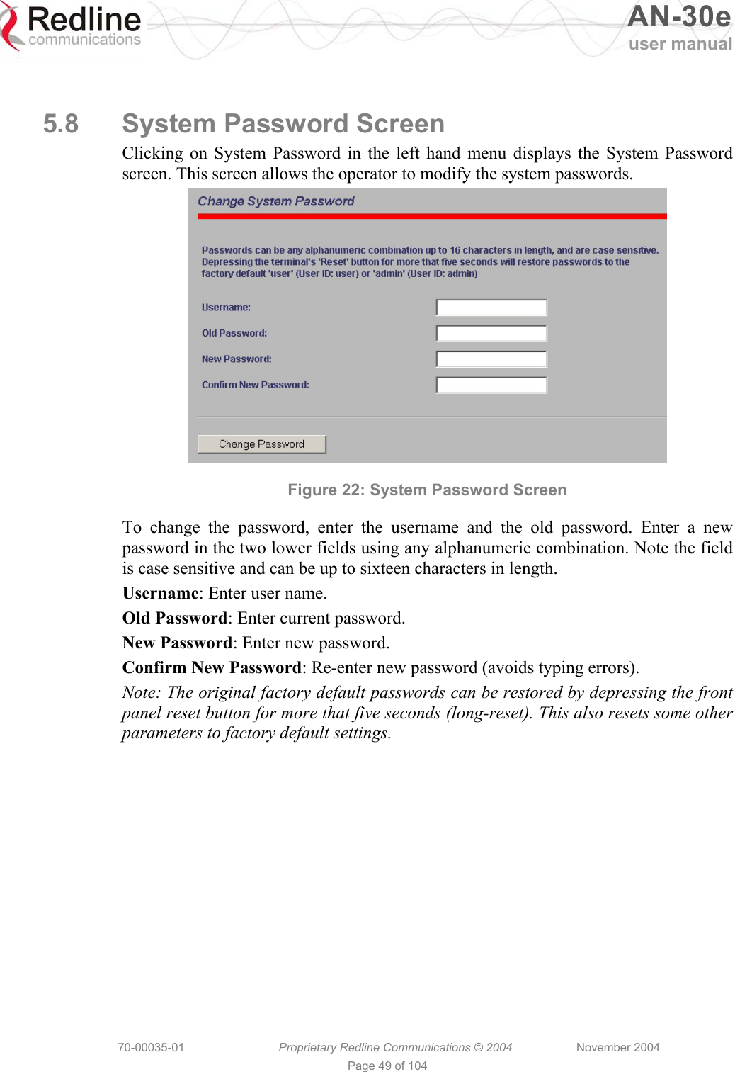
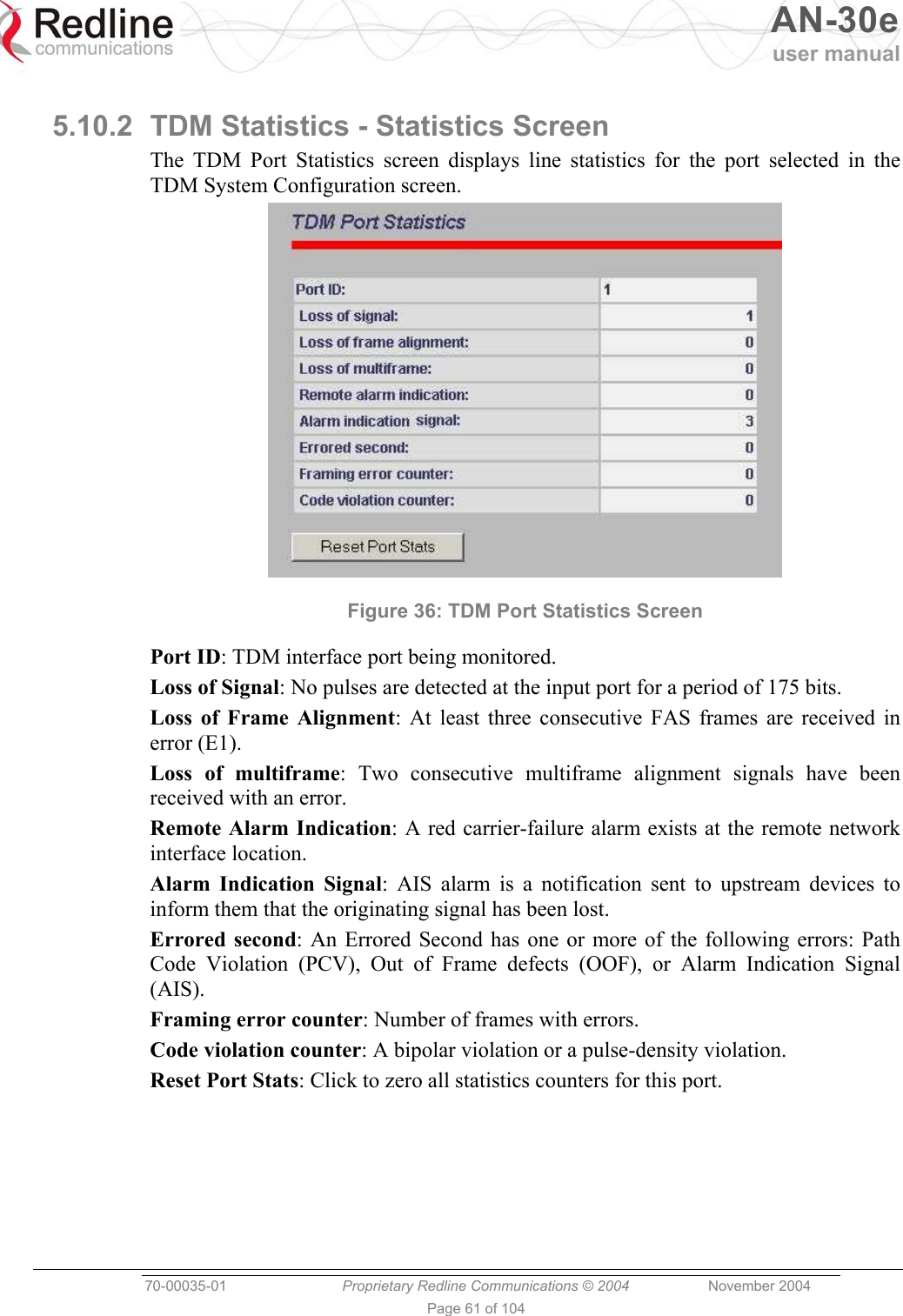
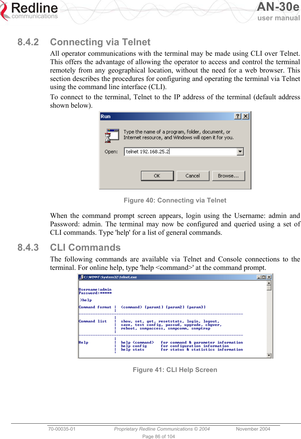
![AN-30e user manual 70-00035-01 Proprietary Redline Communications © 2004 November 2004 Page 33 of 104 5.2 General Information Click on General Information to view general system information, Ethernet LAN address information, and wireless settings. This page includes a view of the terminal front panel LEDs. Figure 12: General Information Screen 5.2.1 System System Name: Displays the user-specified name for the local terminal. System Details: Displays the user-specified information such as location, telephone number, and/or contact number. Hardware Revision: Displays the detected hardware revision level for this terminal. Outdoor Unit Type: Displays the detected transceiver model number. Master-mode: Displays the user-specified operating mode of the terminal. Yes: System is configured as a sector controller. No: System is configured as a subscriber station. Software Version: Displays the detected software version in use. Time Since System Start: Displays the time [dd/hh/mm/ss] since the system started.](https://usermanual.wiki/Redline-Communications/AN5030EX.USERS-MANUAL-1/User-Guide-492956-Page-33.png)
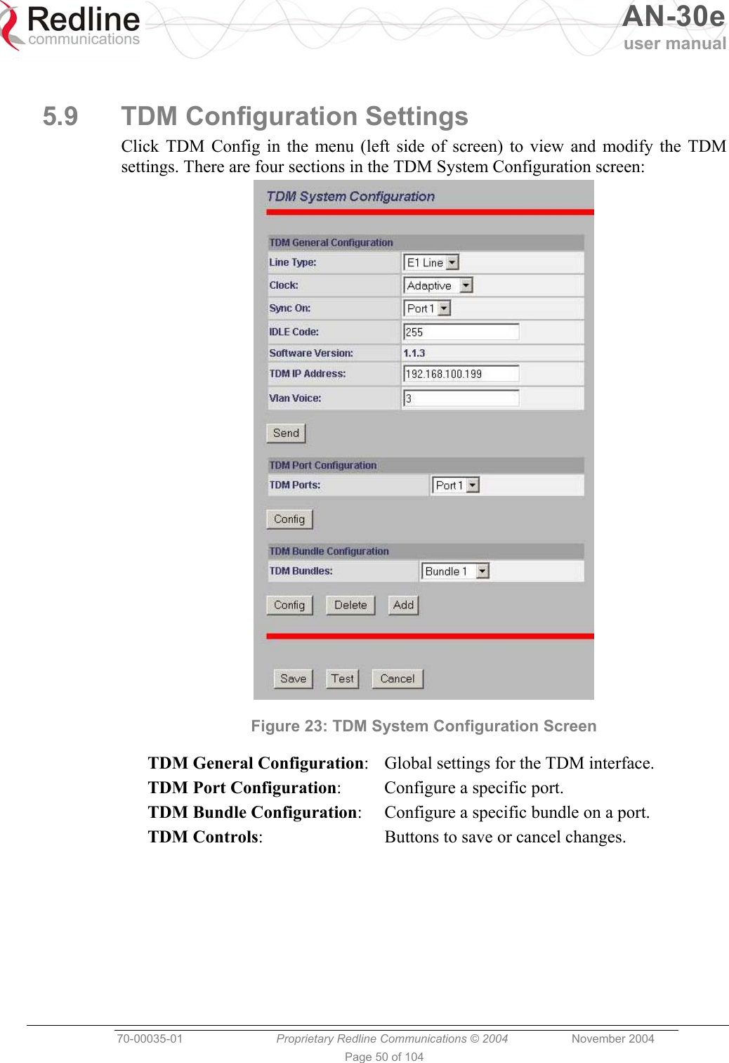
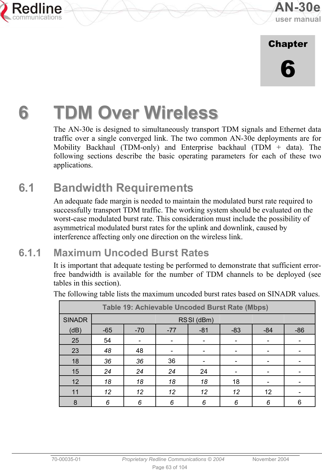
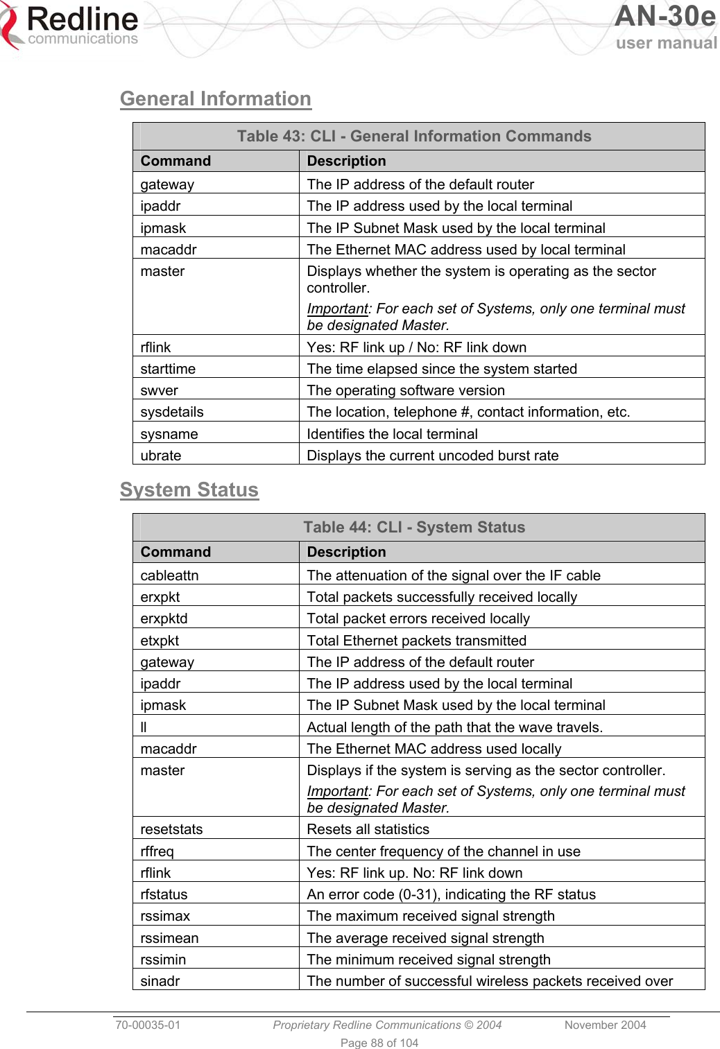
![AN-30e user manual 70-00035-01 Proprietary Redline Communications © 2004 November 2004 Page 35 of 104 5.3 System Status Click System Status in the menu to view system information and Ethernet and wireless statistics. Figure 13: System Status Screen 5.3.1 General Information: System Name: Displays the user-specified name for the local terminal. Software Version: Displays the detected software version in use. RF Link Established: Displays the status of the wireless link. Yes - RF link is established. No - RF link has not been established. Uncoded Burst Rate [Mb/s]: Displays the uncoded burst rate for the link. Master-mode: Displays the user-specified operating mode of the terminal. Yes: System is configured as a sector controller. No: System is configured as a subscriber station. Important: Only one terminal must be designated Master on each wireless link. RF Channel Frequency: Displays the user-specified channel center frequency. Tx Power: Displays the user-specified transmit power level. Cable Attenuation: Displays the measured attenuation level for the 800 MHz signal over the IF cable.](https://usermanual.wiki/Redline-Communications/AN5030EX.USERS-MANUAL-1/User-Guide-492956-Page-35.png)
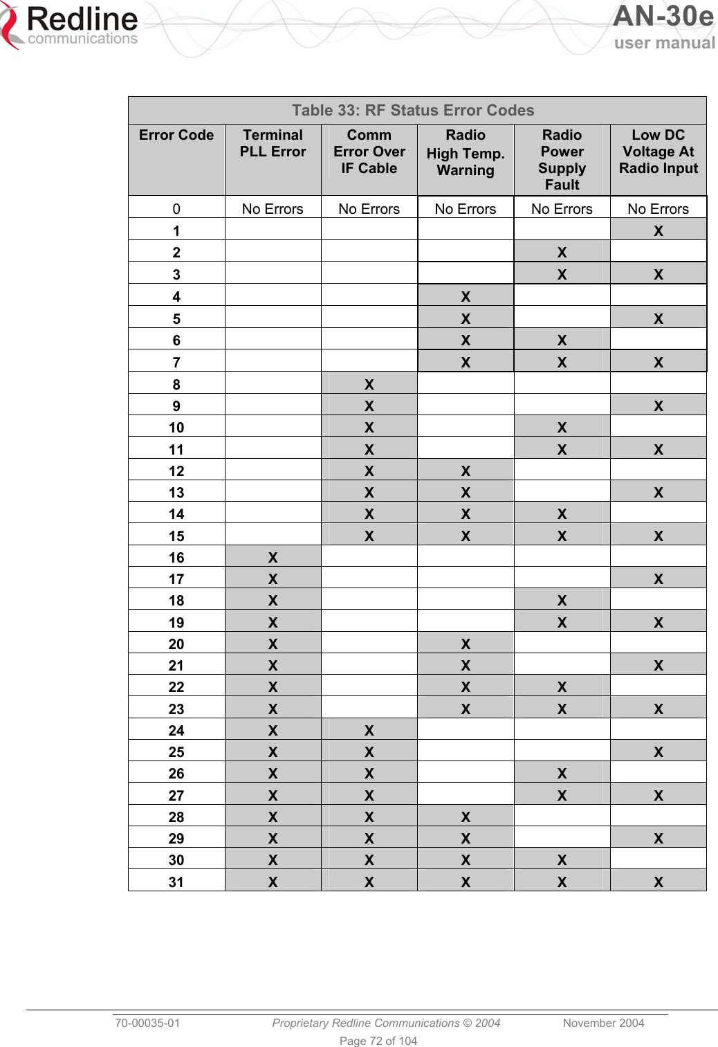
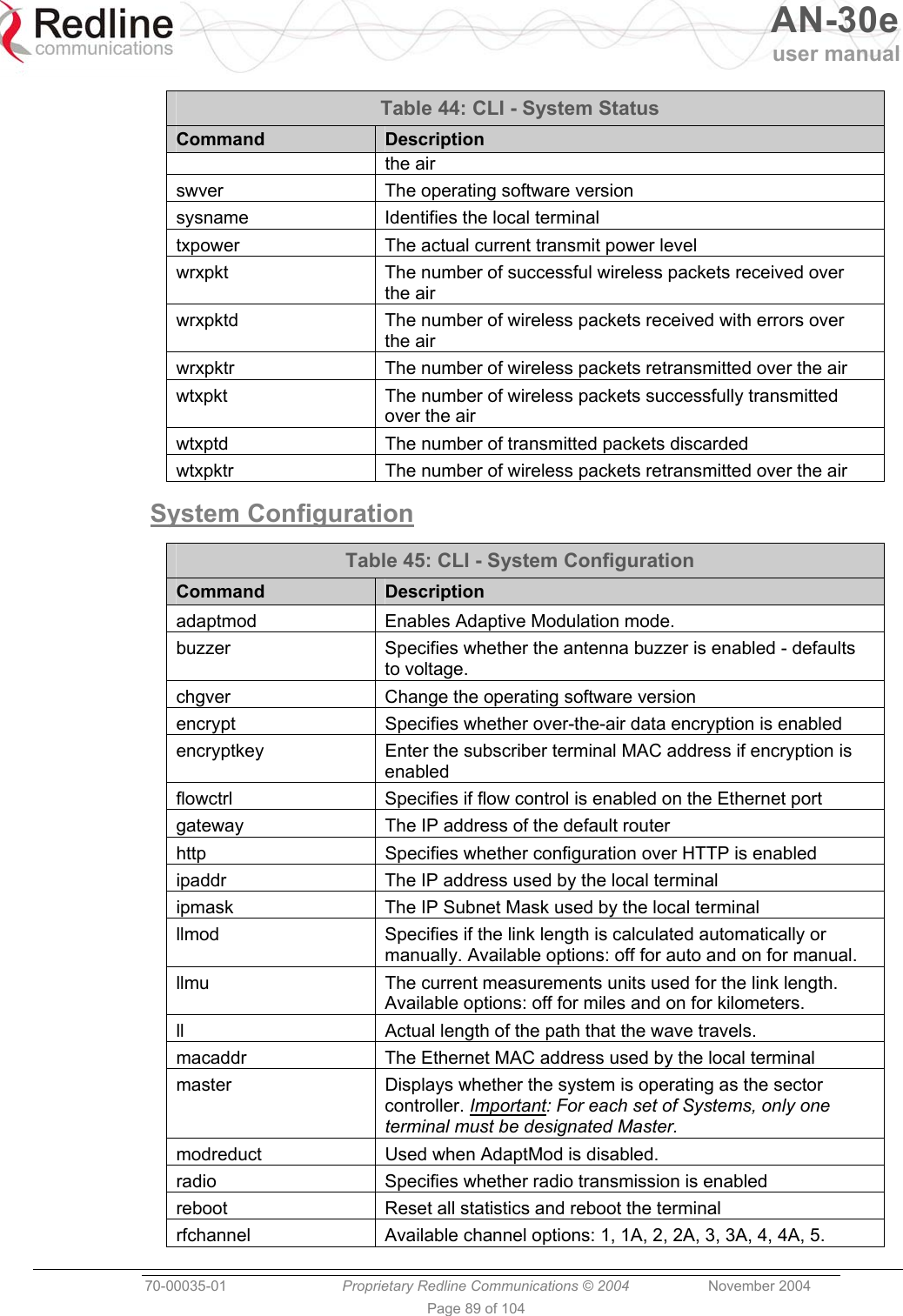
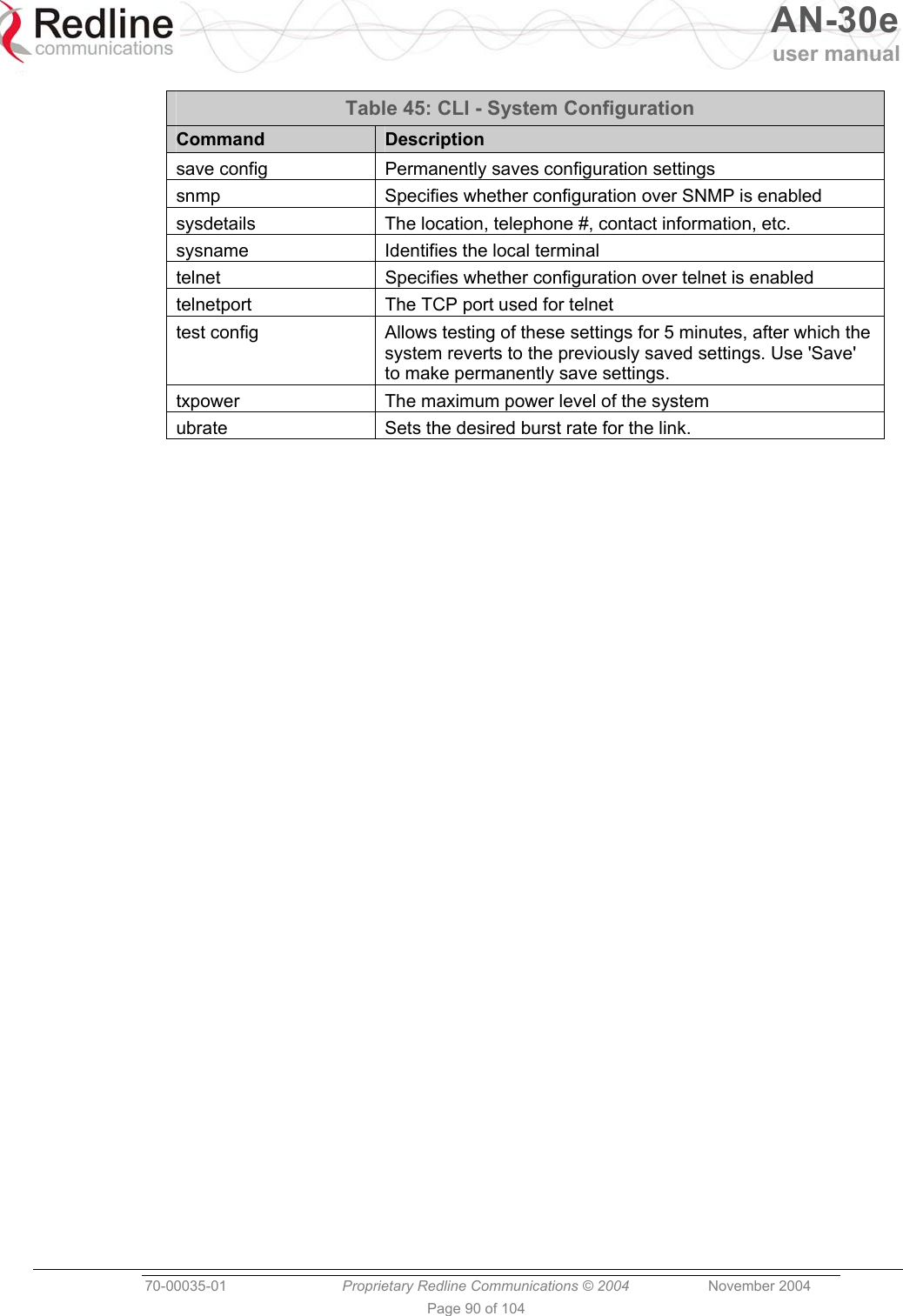
![AN-30e user manual 70-00035-01 Proprietary Redline Communications © 2004 November 2004 Page 36 of 104 Link Distance [Miles or Km]: Displays the user-specified distance between the two ends of the wireless link. RF Status [Error Code]: Displays an error code indicating the status of the system RF components. Code 'zero' indicates normal operation. See the RF Status Error Code Table 33: RF Status Error Codes on page 72 for details. Ethernet MAC Address: Displays the unique Ethernet address of this terminal. IP Address: Displays the user-specified IP address of this terminal. IP Subnet Mask: Displays the user-specified subnet mask. Default Gateway Address: Displays the user-specified IP address of the default router/gateway on the local Ethernet segment. 5.3.2 Ethernet LAN Statistics: Rx packets: Displays the number of non-errored packets received. Rx packets - Discarded: Displays the number of errored packets received. Tx Packets: Displays the total number of Ethernet packets transmitted. 5.3.3 Wireless Statistics: Received Signal Strength: Min: Displays the minimum received signal strength measured since the last screen refresh. Received Signal Strength: Mean: Displays the average received signal strength, computed since the last screen refresh. Received Signal Strength: Max: Displays the maximum received signal strength measured since the last screen refresh. SINADR: Displays the average signal to interference, noise and distortion ratio measured since the last screen refresh. Rx Packets: Displays the total number of wireless packets received over the air. Rx Packets: Retransmitted: Displays the number of wireless packets retransmitted over the air. Rx Packets: Discarded: Displays the number of wireless packets received over the air with errors due to degradation in the RF link. Tx Packets: Displays the number of wireless packets (including Ethernet frames and error correction bytes) successfully transmitted over the air. Tx Packets: Retransmitted: Displays the number of wireless packets retransmitted over the air. The retransmission scheme is based on the Automatic Repeat Request (ARQ) algorithm that detects when packets are lost, and makes a request to the MAC scheduler to repeat transmission of the lost packets. Tx Packets: Discarded: Displays the number of transmitted wireless packets discarded by the subscriber terminal, due to degradation in the RF link. 5.3.4 Statistics Control Button: Reset Statistics: Click this button to zero all counters.](https://usermanual.wiki/Redline-Communications/AN5030EX.USERS-MANUAL-1/User-Guide-492956-Page-36.png)
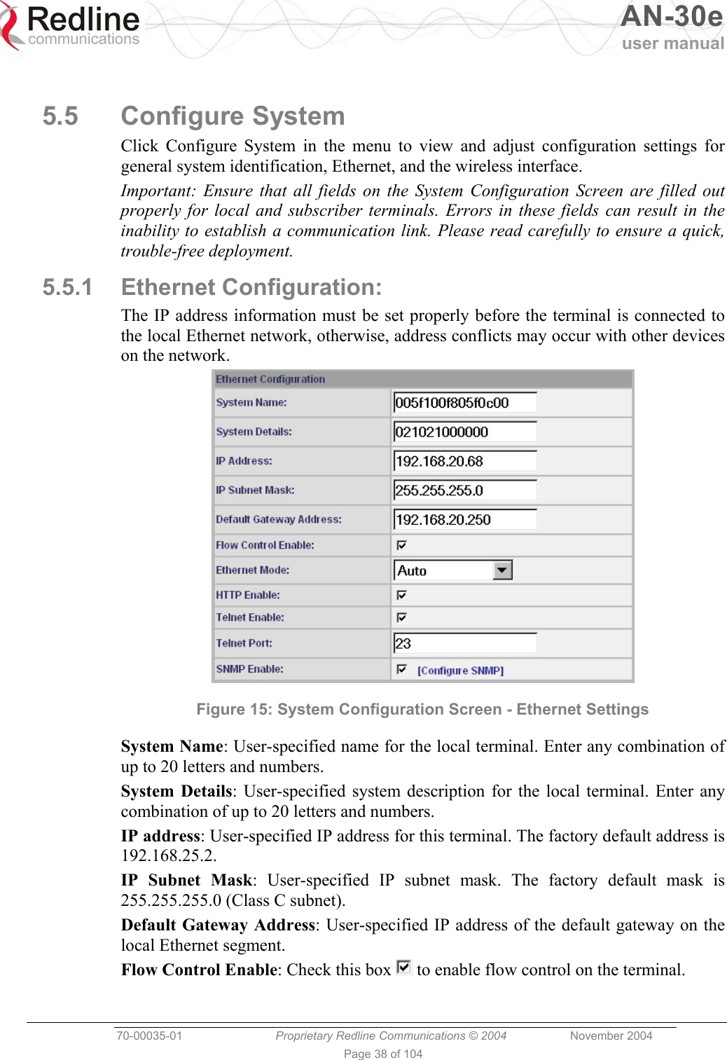
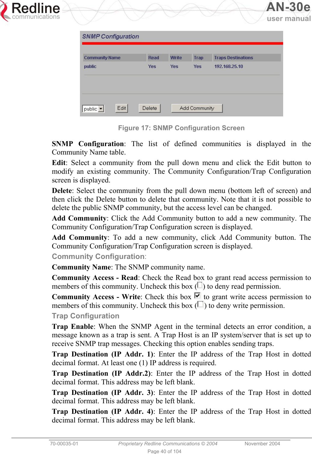
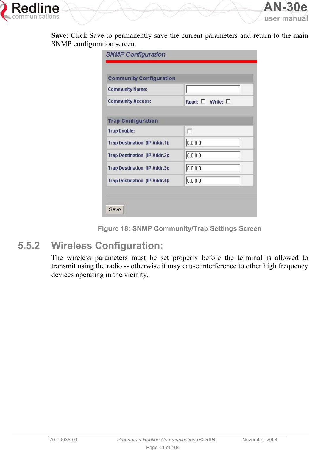
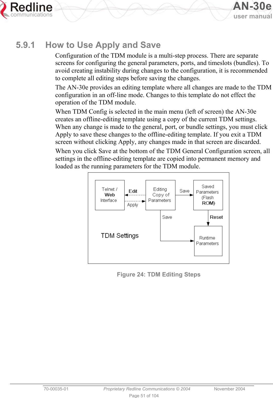
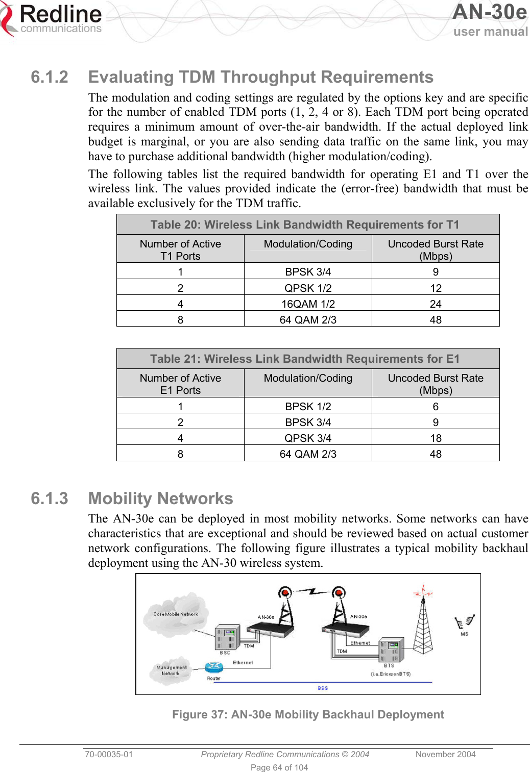
![AN-30e user manual 70-00035-01 Proprietary Redline Communications © 2004 November 2004 Page 39 of 104 When you enable the Flow Control option, the AN-50e tests the p (priority) setting for any 802.1Q packet received on the Ethernet port. If the packet priority is set to a value of zero to three, the data is assigned to a low priority queue. If the packet priority is set to a value of 4-7, the data is assigned to the high priority queue. All high priority traffic is transmitted before any low priority traffic is transmitted. This ensures that high priority traffic (such as VoIP packets) receives priority over lower priority data-only traffic. Ethernet Mode: Select the operating mode of the Ethernet port. Auto - Auto-negotiate the speed connection speed. 10 Mbps HD - Operate at 10Base-T half duplex only. 10 Mbps FD - Operate at 10Base-T full duplex only. 100 Mbps HD - Operate at 100Base-T half duplex only. 100 Mbps FD - Operate at 100Base-T full duplex only. HTTP Server Enable: Check this box to enable the HTTP (Web) interface. If this setting is disabled -- this screen is not available. Refer to the CLI commands section in the Appendix for methods to enable the HTTP interface using the Telnet interface or the console port. Telnet Enable: Check this box to enable Telnet sessions. Refer to the CLI commands in the Appendix. Telnet Port: Enter the Telnet port address. The default Telnet port is 23. The port can be changed to any other number between 23 and 65,000, excluding port 80. SNMP Enable: Check this box to enable the Simple Network Management Protocol (SNMP) agent. When this item is checked, clicking on the blue text [Configure SNMP] beside the checkbox displays the SNMP Configuration screen. See section 0: SNMP Settings on page 39 for additional information on setting up SNMP for the AN-30e. SNMP Settings Screen Click Configure SNMP (blue text) on the System Configuration screen to view and edit the SNMP settings. The blue text appears when the SNMP Enable box is checked. Figure 16: System Configuration Screen - SNMP Access The SNMP Configuration screen displays a list of the current communities. The control buttons can be used to add, edit, or delete communities.](https://usermanual.wiki/Redline-Communications/AN5030EX.USERS-MANUAL-1/User-Guide-492956-Page-39.png)
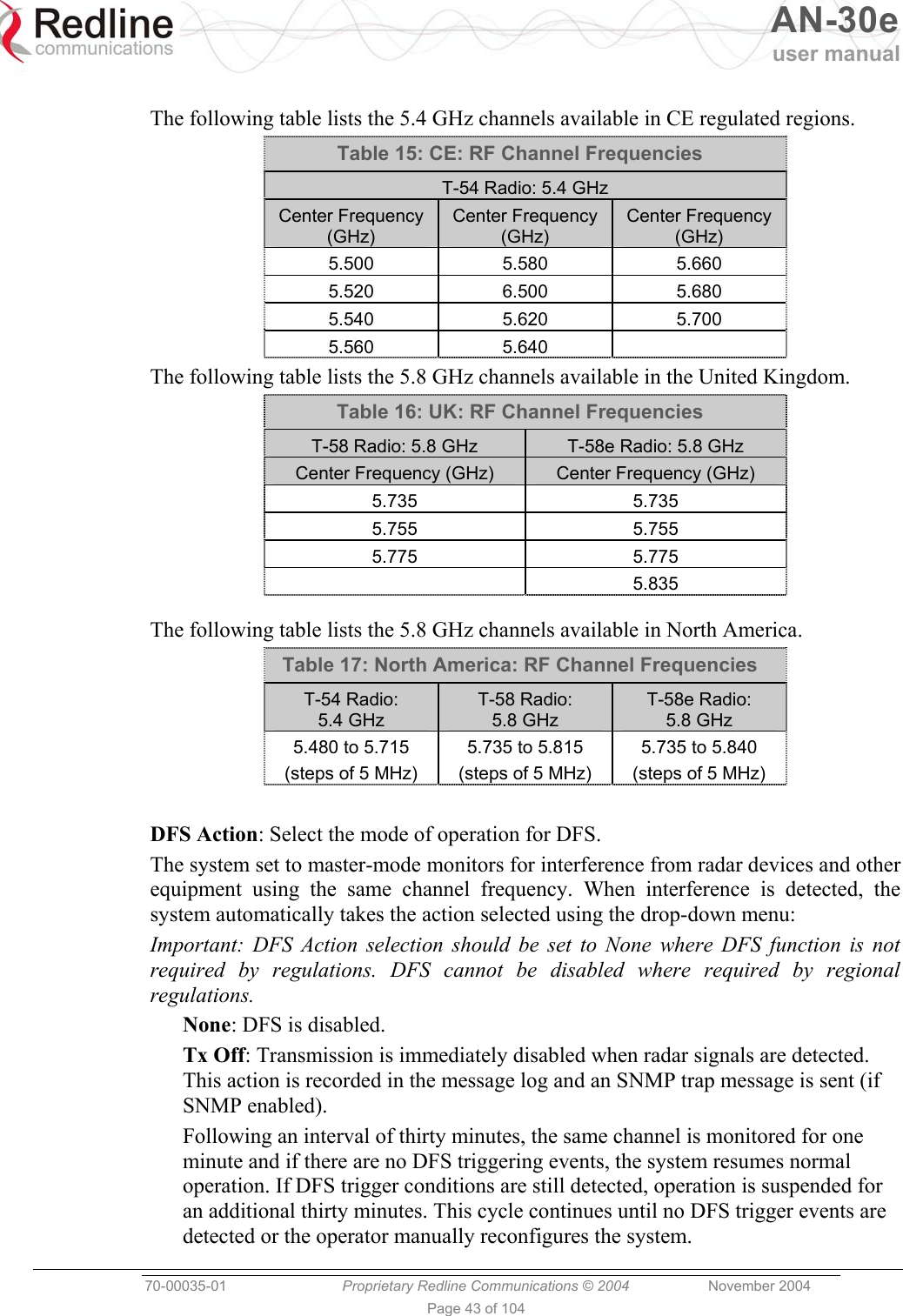
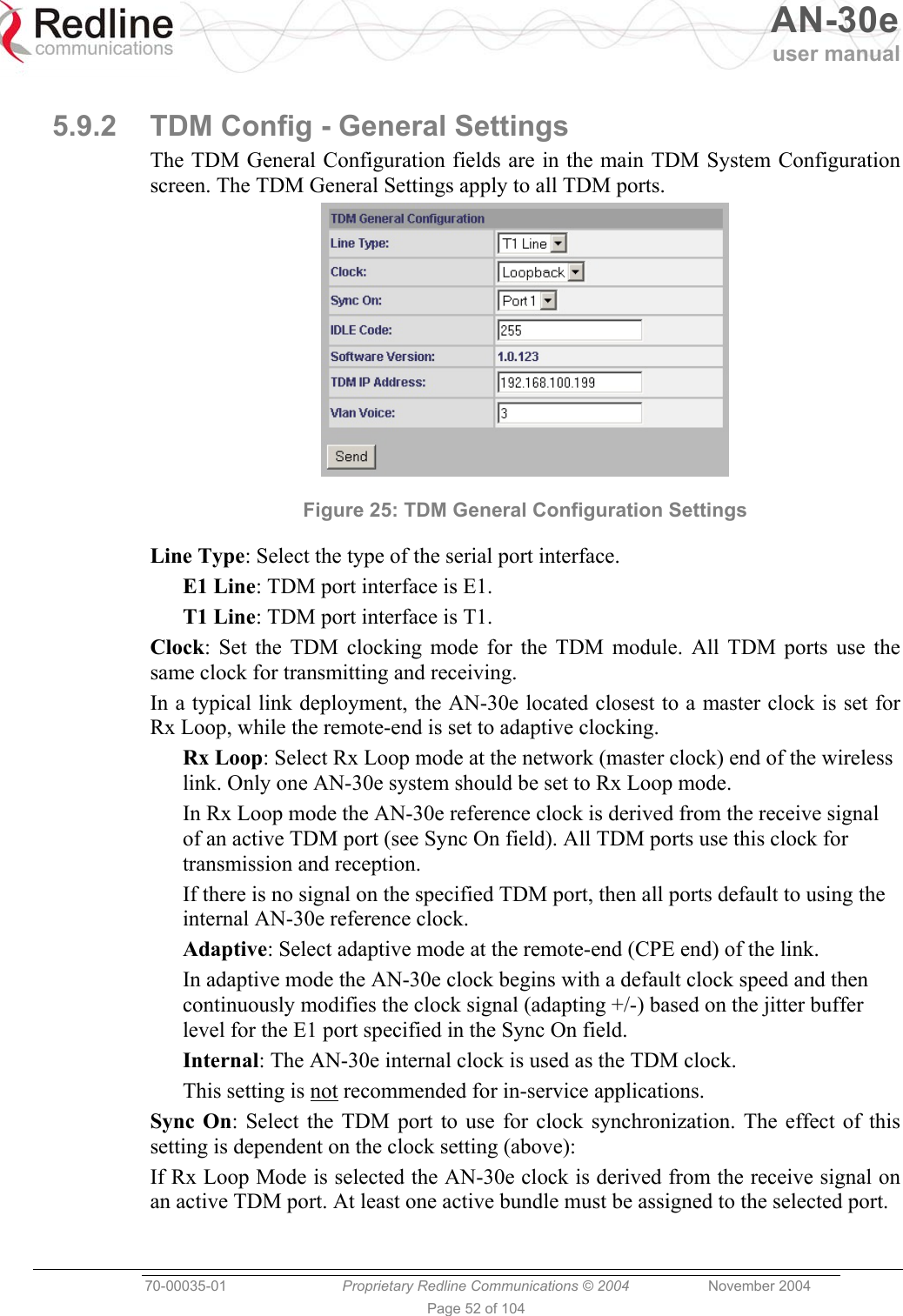
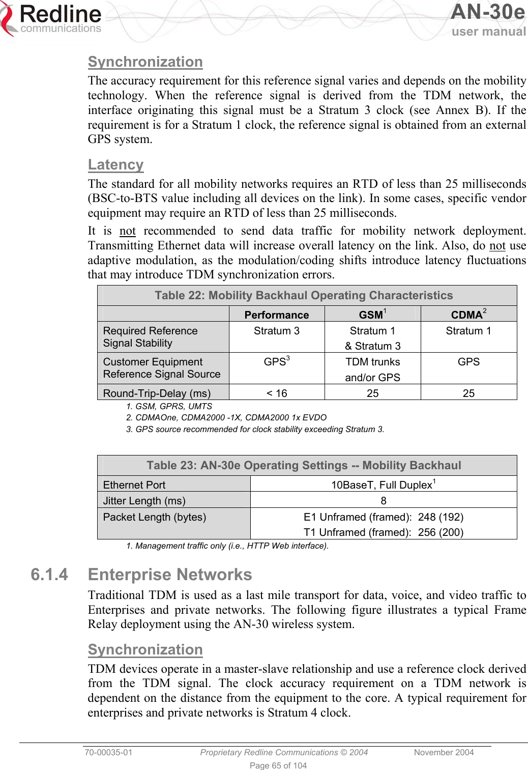
![AN-30e user manual 70-00035-01 Proprietary Redline Communications © 2004 November 2004 Page 42 of 104 Figure 19: System Configuration Screen - Wireless Settings RF Freq. [MHz]: The system is shipped with a default RF setting. This setting must be changed before allowing the radio to transmit. Channel availability is dependent on the regional regulatory requirements. Enter the channel center frequency of the system. The table below specifies the center frequencies of each permitted channel. To avoid interference, the channel frequencies of two links operating within close proximity must be separated at least twenty MHz. The availability of frequency bands listed in the following tables is based on the factory entered option key. Auto Scan: Check this box to enable subscriber systems to scan the frequency band for active base stations. The availability of channels is limited by regional regulations. It is important that this feature is enabled on the subscriber system when the master-end system has DFS Action is set to Chg Freq. This setting allows automatic link recovery following a DFS event. Additional detailed installation information is available in the manual titled "Installation Guidelines for Redline AN-30e PTP Systems" also provided on AN-30e CD-ROM. This guide provides instructions for site planning and installation including weatherproofing and antenna alignment.](https://usermanual.wiki/Redline-Communications/AN5030EX.USERS-MANUAL-1/User-Guide-492956-Page-42.png)
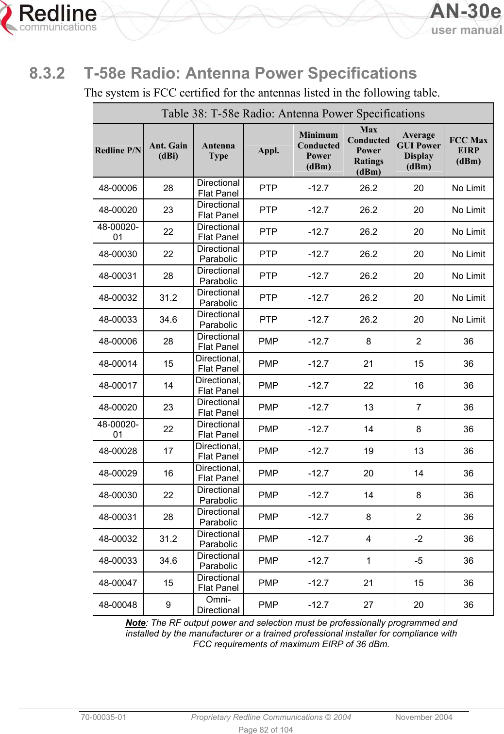
![AN-30e user manual 70-00035-01 Proprietary Redline Communications © 2004 November 2004 Page 44 of 104 Chg Freq: Relocate transmission to alternative frequency immediately when radar signals are detected. This action is recorded in the message log and a trap message is sent (if SNMP enabled). The new channel is selected based on allowable frequencies for the regulatory region of that installation. The channel is monitored for one minute before the system is allowed to transmit. If DFS triggering events are detected, the next available channel is selected and monitored. The system is not allowed to return to a channel on which DFS trigger events were detected for a period of thirty minutes. If DFS trigger events are detected on all channels the system suspends operation until the thirty-minute time interval expires for at least one channel. DFS Antenna Gain: Enter the gain (dBm) for the system antenna. It is important that this value is set to correctly match the antenna gain. If the antenna gain is set higher than the actual antenna gain, the DFS is less sensitive to detecting interference, and the system is not operating in compliance with the UK/ETSI standard. If the antenna gain is set lower than the actual antenna gain, the DFS is more sensitive to detecting interference and may cause false triggers. Important: The DFS Antenna Gain must be set when DFS is required by regional regulations. Tx Power [dBm]: Enter the default Tx power level (dBm). Section 8.3: Antenna and Power Specifications on page 81 lists the maximum transmit power setting based on the antenna gain for a series of frequency settings. There are restrictions on the maximum transmit power settings when operating at data rates above 24 Mb/s. Note: In some countries outside of North America, the maximum operational power per channel for a specific antenna is limited in accordance to maximum allowable EIRP levels for the region. Refer to the CE notice in the first section of this manual. ATPC Enable: Check this box to enable the ATPC on the system operating in master-mode. Both systems automatically adjust the Tx power levels based on feedback received from the system at the other end of the link. Important: ATPC cannot be disabled where required by regional regulations. Adaptive Modulation: Check this box to enable adaptive modulation mode. When adaptive modulation is enabled, the system measures RF performance (BER) and automatically adjusts to the highest available modulation/coding combination. If packet errors exceed one in one million, the system automatically steps down the modulation/coding to maintain the link at an acceptable BER rate. It is not recommended to enable adaptive modulation mode when using TDM traffic. Transient fade conditions may reduce the system throughput to a level incapable of supporting TDM transport. When dynamic modulation is disabled, the Uncoded Burst Rate and the Modulation Reduction Level settings must be set manually. Adequate testing must be performed to ensure that sufficient error-free bandwidth is available for the number of TDM channels to be deployed.](https://usermanual.wiki/Redline-Communications/AN5030EX.USERS-MANUAL-1/User-Guide-492956-Page-44.png)
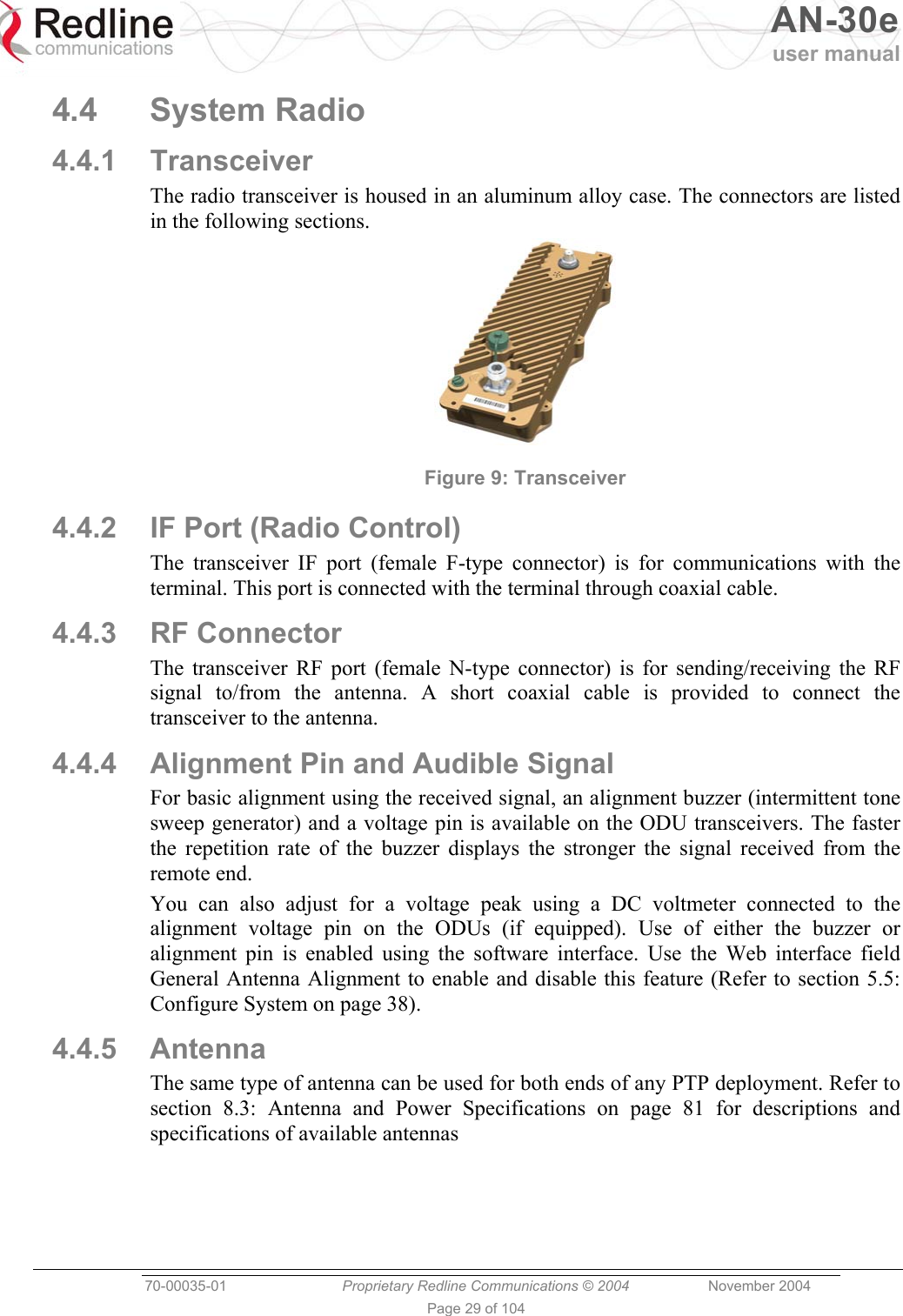
![AN-30e user manual 70-00035-01 Proprietary Redline Communications © 2004 November 2004 Page 45 of 104 Modulation Reduction Level: This manual setting specifies how many levels the system must drop in modulation during re-transmission of erroneous wireless packets. The level can be set from 0-7, with '2' being the recommended value. Valid only when Adaptive Modulation is disabled. Uncoded Burst Rate [Mb/s]: Select the desired uncoded burst rate for the link. Master-mode: Check this box to operate this system as a sector controller. Each PTP link is comprised of a sector controller and a subscriber system. Check the Master tick box in the Configure System screen of the web interface to configure a system to operate as a sector controller. The sector controller establishes and manages the bi-directional data link with the subscriber system. Uncheck the Master tick box in the to configure the system to operate as the subscriber station. Important: Only one system in a wireless link must be set for Master-mode. Software Version: Select the version of the system software to be loaded when the system is rebooted. The system includes flash memory to hold two independent software images. This allows updates to be uploaded without disrupting operation of the system. See Upload Software Section 5.6: for additional details. Encryption Enable: Check this box to enable over-the-air encryption. Encryption must be enabled or disable on both communicating or the system is unable to transfer any Ethernet packets. See also Encryption key following. Encryption Key: The correct encryption key must be entered on both communicating systems when encryption is enabled. Enter the MAC address of the communicating AN-30e system as the data encryption key for each system. Link Length Mode: Method for specifying the distance between AN-30e systems. Auto: Distance calculated automatically (recommended). Manual: Operator enters distance. Link Measurements Units: Select the units for the Link Length Mode field. Miles: Link distance is displayed in miles. Kilometers: Link distance is displayed in kilometers. Link Length: Enter the actual (maximum) distance between the pair of AN-30e systems. Valid only when Link Length Mode is set for Manual. General Antenna Alignment: Check this box to enable the antenna alignment audible tone generator in the transceiver. Radio Enable: Check this box to enable the radio transmitter.](https://usermanual.wiki/Redline-Communications/AN5030EX.USERS-MANUAL-1/User-Guide-492956-Page-45.png)

![AN-30e user manual 70-00035-01 Proprietary Redline Communications © 2004 November 2004 Page 87 of 104 General Commands Table 42: CLI - General Commands Command Description chgver Swaps the operating and secondary software versions get Get <parameter name> displays the value for a status parameter. For configuration parameters, use Set command. login Allows login under a different username and password logout Disconnects user from the terminal. passwd Change password for user. passwd <username> <newpassword> reboot Reboots the terminal. Reboot <time in seconds> resetstats Resets all statistics save config Permanently saves system configuration settings. This command is required to activate all Configuration settings set previously save snmp Permanently saves SNMP configuration settings. This command is required to activate all SNMP settings set previously. set Set one configuration parameter: <parameter name> [<value>] Without <value>, ‘set’ returns the actual value for configuration parameters. For status parameters, use the Get command. show config Returns a list of all System Configuration parameters. show log Returns a list of current system log entries. show snmp Returns a list of all SNMP communities and settings. show stats Returns a list of all System Status parameters. snmpaccess Modify access rights for a community (see snmpcomm) snmpaccess <community name> <access> snmpcomm To add a new SNMP community: snmpcomm add <community name> <access> <access> can be: r,w,t or any combination To delete an SNMP community snmpcomm del <community name> snmptrap To add a trap destination for an SNMP community: snmptrap add <community name> <IP destination> To delete a trap destination for an SNMP community: snmptrap del <community name> <IP destination> test config Allows testing of configuration settings for 5 minutes, after which the system reverts to the previously saved settings. To make settings permanent use 'save' command. upgrade Begin a software upload. upgrade <ipaddr> <filename>](https://usermanual.wiki/Redline-Communications/AN5030EX.USERS-MANUAL-1/User-Guide-492956-Page-87.png)
![AN-30e user manual 70-00035-01 Proprietary Redline Communications © 2004 November 2004 Page 92 of 104 TDM General Commands Form of command is: tdm set command [param1] [param2] [param3] Table 46: CLI - TDM General Commands CLI Command Description clock CLK_IND Clocking mode on E1 module. fanstate FAN Status of fan. gateway IPGATEWAY IP address of the default gateway. hostname HOST Hostname of the E1 module. ipaddr IP The IP address of the E1 module. ipmask IP Network mask. key Option key (permitted line types, number of lines, user data) on the E1 module. keyidlecode IDLECODE Idle code for unused timeslots on all of the serial interface ports. line LINE_TYPE Line type on the E1 module (if permitted by the option key). 0=T1, 1=E1 showactivebundles Total active bundles and list the IDs of those bundles. showgen CONFIG General configuration parameters from running or startup config. softver Coded software version. syncon SYNC_ON The serial interface port to be used as clocking reference. vlandata VID_DATA The VLAN ID used to tag all ingress traffic at the data port of the AN-30e. vlanvoice VID_VOICE The VLAN ID used to tag all traffic from the E1 ports of the AN-30e. TDM Set and Get operations The get operation returns values from the running configuration. The set operation applies changes only to the temporary configuration. Use the 'tdm test' command to try the settings for five minutes or the 'tdm save' command to save the changes permanently. All commands are of the following format: tdm set operator SN <optional parameters> tdm get operator SN command Table 47: CLI - TDM Set and Get Commands CLI Command Description get Retrieve the parameter value from a running configuration. set Modify the specified parameter value in the temporary configuration. show List all parameter values of the command category.](https://usermanual.wiki/Redline-Communications/AN5030EX.USERS-MANUAL-1/User-Guide-492956-Page-92.png)