Redline Communications AN5030EX AN-50e/AN-30e System w/ T-58e Radio User Manual 70 00035 01
Redline Communications Inc. AN-50e/AN-30e System w/ T-58e Radio 70 00035 01
Contents
- 1. USERS MANUAL 1
- 2. USERS MANUAL 2
USERS MANUAL 1
70-00035-01 Proprietary Redline Communications © 2004 November 2004
Page 1 of 104
AN-30e PTP System
User Manual

AN-30e
user manual
70-00035-01 Proprietary Redline Communications © 2004 November 2004
Page 2 of 104
Copyright Information
All rights reserved June 2004. The information in this document is proprietary to
Redline Communications Inc. This document may not in whole or in part be copied,
reproduced, or reduced to any medium without prior consent, in writing, from Redline
Communications Incorporated.
Copyright © 2004 Redline Communications Inc.
Contact Information Redline Communications Inc.
302 Town Centre Blvd.
Markham, ON
Canada L3R 0E8
Web site: http://www.redlinecommunications.com
Sales Inquiries:
North American
Toll-free sales line
International
nainfo@redlinecommunications.com
1-866-633-6669
intlinfo@redlinecommunications.com
Support:
Email
Telephone
support@redlinecommunications.com
Contact your Redline Distributor
Product Registration http://www.redlinecommunications.com
Click Support
User ID: Register
Password: Redline
Disclaimer
The statements, configurations, technical data, and recommendations in this
document are believed to be accurate and reliable, but are presented without
express or implied warranty. Additionally, Redline makes no representations or
warranties, either expressed or implied, regarding the contents of this product.
Redline Communications shall not be liable for any misuse regarding this product.
The information in this document is subject to change without notice.
70-00035_01_AN_30e_UserMan-041111a.doc

AN-30e
user manual
70-00035-01 Proprietary Redline Communications © 2004 November 2004
Page 3 of 104
TABLE OF CONTENTS
1 Important Safety & Service Notices....................................................... 9
1.1 Safety Warnings ........................................................................................ 9
1.2 Important Warning Symbols .................................................................... 10
1.3 Important Service Information ................................................................. 10
1.4 FCC Notice .............................................................................................. 11
1.5 UL Information ......................................................................................... 12
1.6 CE Notice ................................................................................................ 12
1.7 Lightning Protection................................................................................. 13
1.8 Product Information ................................................................................. 14
2 Getting Started....................................................................................... 15
2.1 Terms Used in this Manual...................................................................... 16
3 System Overview................................................................................... 17
3.1 TDM over Wireless .................................................................................. 18
3.1.1 Theory of Operation............................................................................. 18
3.1.2 TDM Configuration .............................................................................. 18
4 Physical Description ............................................................................. 21
4.1 Quick Install Guide .................................................................................. 21
4.2 Unpacking the AN-30e ............................................................................ 21
4.3 AN-30e Terminal ..................................................................................... 22
4.3.1 Mounting.............................................................................................. 22
4.3.2 Power Supply ...................................................................................... 22
4.3.3 Time Synchronization Port .................................................................. 22
4.3.4 Wireless Section.................................................................................. 22
4.3.5 Ethernet Section .................................................................................. 24
4.3.6 System Section.................................................................................... 26
4.3.7 The TDM Interface............................................................................... 27
4.4 System Radio .......................................................................................... 29
4.4.1 Transceiver.......................................................................................... 29
4.4.2 IF Port (Radio Control) ........................................................................ 29
4.4.3 RF Connector ...................................................................................... 29
4.4.4 Alignment Pin and Audible Signal........................................................ 29
4.4.5 Antenna ............................................................................................... 29
4.4.6 Antenna Mounting Bracket .................................................................. 30
5 Using the Web Interface........................................................................ 31
5.1 System Menu........................................................................................... 31
5.2 General Information................................................................................. 33
5.2.1 System................................................................................................. 33
5.2.2 Ethernet: .............................................................................................. 34
5.2.3 Wireless:.............................................................................................. 34
5.3 System Status ......................................................................................... 35
5.3.1 General Information:............................................................................ 35
5.3.2 Ethernet LAN Statistics:....................................................................... 36
5.3.3 Wireless Statistics: .............................................................................. 36
5.3.4 Statistics Control Button: ..................................................................... 36

AN-30e
user manual
70-00035-01 Proprietary Redline Communications © 2004 November 2004
Page 4 of 104
5.4 System Logs............................................................................................ 37
5.5 Configure System .................................................................................... 38
5.5.1 Ethernet Configuration:........................................................................ 38
5.5.2 Wireless Configuration: ....................................................................... 41
5.5.3 System Configuration Buttons ............................................................. 46
5.6 Upload Software ...................................................................................... 47
5.7 Product Options....................................................................................... 48
5.7.1 Entering Option Keys........................................................................... 48
5.7.2 TDM Options ....................................................................................... 48
5.7.3 Ethernet Options.................................................................................. 48
5.8 System Password Screen ....................................................................... 49
5.9 TDM Configuration Settings .................................................................... 50
5.9.1 How to Use Apply and Save................................................................ 51
5.9.2 TDM Config - General Settings............................................................ 52
5.9.3 TDM Config - Port Settings.................................................................. 54
5.9.4 TDM Config - Bundle Selection ........................................................... 56
5.9.5 TDM System Configuration Control Buttons........................................ 59
5.10 TDM Statistics ......................................................................................... 60
5.10.1 TDM Statistics - Port Selection............................................................ 60
5.10.2 TDM Statistics - Statistics Screen........................................................ 61
6 TDM Over Wireless................................................................................ 63
6.1 Bandwidth Requirements ........................................................................ 63
6.1.1 Maximum Uncoded Burst Rates .......................................................... 63
6.1.2 Evaluating TDM Throughput Requirements ........................................ 64
6.1.3 Mobility Networks ................................................................................ 64
6.1.4 Enterprise Networks ............................................................................ 65
6.1.5 Evaluating Ethernet Throughput.......................................................... 67
6.1.6 Clock Synchronization ......................................................................... 68
7 Diagnostics and Troubleshooting ....................................................... 69
7.1 Factory Default Settings .......................................................................... 69
7.2 Troubleshooting the Web Interface ......................................................... 70
7.3 Troubleshooting The RF.......................................................................... 71
7.4 System Error Log Messages ................................................................... 73
7.5 Replacing System Fuse........................................................................... 75
8 Appendix ................................................................................................ 77
8.1 System Specifications ............................................................................. 77
8.2 DC Power Supply Cable Connections..................................................... 80
8.3 Antenna and Power Specifications.......................................................... 81
8.3.1 T-58 Radio: Antenna Power Specifications ......................................... 81
8.3.2 T-58e Radio: Antenna Power Specifications ....................................... 82
8.3.3 T-54 Radio: Maximum RF Power vs. Antenna Gain............................ 83
8.3.4 T-54 Radio: Operational Power (FCC) ................................................ 84
8.4 CLI Interface ............................................................................................ 85
8.4.1 Console (RS-232) Port ........................................................................ 85
8.4.2 Connecting via Telnet.......................................................................... 86

AN-30e
user manual
70-00035-01 Proprietary Redline Communications © 2004 November 2004
Page 5 of 104
8.4.3 CLI Commands.................................................................................... 86
8.4.4 Sample TDM CLI Setup Scripts........................................................... 96
8.5 About SNMP.......................................................................................... 100
8.6 Glossary Of Terms ................................................................................ 101

AN-30e
user manual
70-00035-01 Proprietary Redline Communications © 2004 November 2004
Page 6 of 104
LIST OF TABLES
Table 1: Terms .................................................................................................... 16
Table 2: Wireless Link Diagnostics ..................................................................... 23
Table 3: Wireless Signal Diagnostics .................................................................. 24
Table 4: terminal LAN Ethernet Port Pinout ........................................................ 24
Table 5: Ethernet Link/Act Diagnostics ............................................................... 25
Table 6: Ethernet 100 Diagnostics ...................................................................... 25
Table 7: Ethernet Collision Diagnostics............................................................... 26
Table 8: System Power Diagnostics.................................................................... 26
Table 9: Front Panel Reset Switch...................................................................... 27
Table 10: TDM Port RJ-48 Pinout ....................................................................... 27
Table 11: TDM RJ-48 CPE Connection Cable .................................................... 28
Table 12: TDM Port Alarm Condition LEDs......................................................... 28
Table 13: Web Screens....................................................................................... 32
Table 14: Default System Users.......................................................................... 32
Table 15: CE: RF Channel Frequencies ............................................................. 43
Table 16: UK: RF Channel Frequencies ............................................................. 43
Table 17: North America: RF Channel Frequencies ........................................... 43
Table 18: Default Bundle Numbers ..................................................................... 58
Table 19: Achievable Uncoded Burst Rate (Mbps) ............................................. 63
Table 20: Wireless Link Bandwidth Requirements for T1 ................................... 64
Table 21: Wireless Link Bandwidth Requirements for E1 ................................... 64
Table 22: Mobility Backhaul Operating Characteristics....................................... 65
Table 23: AN-30e Operating Settings -- Mobility Backhaul ................................. 65
Table 24: Enterprise Backhaul Latency Requirements ....................................... 66
Table 25: Enterprise Backhaul Operating Parameters........................................ 66
Table 26: AN-30e Operating Settings -- Enterprise Backhaul............................. 66
Table 27: Data Rates Available when Using E1.................................................. 67
Table 28: Data Rates Available when Using E1.................................................. 67
Table 29: Stratum Clock Definitions .................................................................... 68
Table 30: Factory Default Settings ...................................................................... 69
Table 31: Web Interface Diagnostics .................................................................. 70
Table 32: RF Errors............................................................................................. 71
Table 33: RF Status Error Codes ........................................................................ 72
Table 34: System Log Messages ........................................................................ 73
Table 35: AN-30e Technical Specifications......................................................... 77
Table 36: DC Power Supply Cable Connections................................................. 80
Table 37: T-58 Radio: Antenna Power Specifications......................................... 81
Table 38: T-58e Radio: Antenna Power Specifications....................................... 82
Table 39: 5.4 GHz Band RF Power vs. Antenna Gain ........................................ 83
Table 40: 5.4 GHz -- Antenna Gain vs. Max. Op. Power .................................... 84
Table 41: Console (RS-232) Port Pinout............................................................. 85
Table 42: CLI - General Commands ................................................................... 87
Table 43: CLI - General Information Commands ................................................ 88
Table 44: CLI - System Status ............................................................................ 88

AN-30e
user manual
70-00035-01 Proprietary Redline Communications © 2004 November 2004
Page 7 of 104
Table 45: CLI - System Configuration ................................................................. 89
Table 46: CLI - TDM General Commands........................................................... 92
Table 47: CLI - TDM Set and Get Commands .................................................... 92
Table 48: CLI - TDM Serial Interface Commands ............................................... 93
Table 49: CLI - TDM DS0 Bundle Commands .................................................... 93
Table 50: CLI - TDM General Statistics Commands ........................................... 93
Table 51: CLI - TDM Ethernet Statistics Commands .......................................... 94
Table 52: CLI - TDM Statistics ............................................................................ 94
Table 53: TDM Save Command Error Codes ..................................................... 95
Table 54: E1 Framed Configuration Script .......................................................... 96
Table 55: T1 Framed Configuration Script .......................................................... 98
Table 56: Glossary of Terms ............................................................................. 101

AN-30e
user manual
70-00035-01 Proprietary Redline Communications © 2004 November 2004
Page 8 of 104
LIST OF FIGURES
Figure 1: AN-30e System: Terminal, Transceiver, and Antenna......................... 15
Figure 2: AN-30e terminal ................................................................................... 17
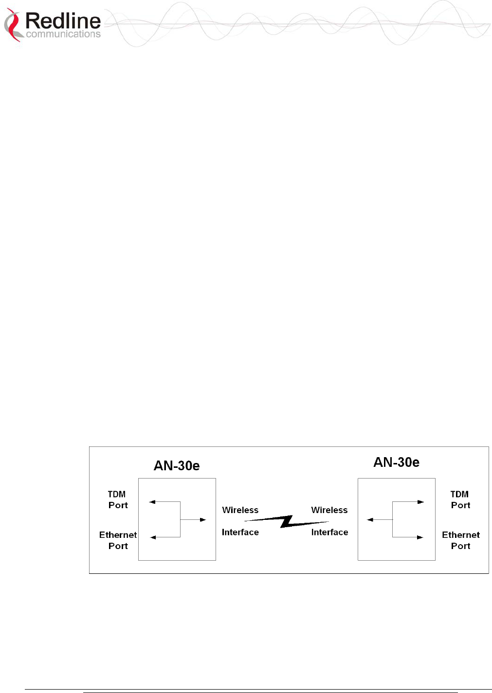
Figure 3: AN-30e Ethernet/TDM Transport ......................................................... 18
Figure 4: AN-30e Multi-Hop Deployment Example ............................................. 20
Figure 5: Front Panel - Wireless LEDs................................................................ 23
Figure 6: RJ-45 Jack Face .................................................................................. 24
Figure 7: Front Panel: Ethernet LEDs ................................................................. 24
Figure 8: Front Panel: Reset Switch and System LEDs...................................... 26
Figure 9: Transceiver .......................................................................................... 29
Figure 10: One-Foot Flat Antenna....................................................................... 30
Figure 11: On-Screen Menu................................................................................ 31
Figure 12: General Information Screen ............................................................... 33
Figure 13: System Status Screen........................................................................ 35
Figure 14: System Logs Screen .......................................................................... 37
Figure 15: System Configuration Screen - Ethernet Settings.............................. 38
Figure 16: System Configuration Screen - SNMP Access .................................. 39
Figure 17: SNMP Configuration Screen .............................................................. 40
Figure 18: SNMP Community/Trap Settings Screen........................................... 41
Figure 19: System Configuration Screen - Wireless Settings ............................. 42
Figure 20: Upload Software Screen .................................................................... 47
Figure 21: AN-30e Product Options Screen........................................................ 48
Figure 22: System Password Screen .................................................................. 49
Figure 23: TDM System Configuration Screen.................................................... 50
Figure 24: TDM Editing Steps ............................................................................. 51
Figure 25: TDM General Configuration Settings ................................................. 52
Figure 26: TDM IP Address Settings................................................................... 53
Figure 27: TDM Port Configuration Settings ....................................................... 54
Figure 28: TDM Port Editing Screen ................................................................... 54
Figure 29: TDM Loopback: Local Mode .............................................................. 55
Figure 30: TDM Loopback: Subscriber Mode...................................................... 55
Figure 31: TDM Loopback: Payload Mode.......................................................... 56
Figure 32: TDM Bundle Selection ....................................................................... 56
Figure 33: TDM Bundle Editing Screen............................................................... 57
Figure 34: TDM Bundle Editing Dialog Box......................................................... 59
Figure 35: TDM Properties/Statistics Screen ...................................................... 60
Figure 36: TDM Port Statistics Screen ................................................................ 61
Figure 37: AN-30e Mobility Backhaul Deployment.............................................. 64
Figure 38: AN-30e Enterprise Deployment ......................................................... 66
Figure 39: Fuse Holder........................................................................................ 75
Figure 40: Connecting via Telnet ........................................................................ 86
Figure 41: CLI Help Screen................................................................................. 86
Figure 42: TDM Configuration Files .................................................................... 91

AN-30e
user manual
70-00035-01 Proprietary Redline Communications © 2004 November 2004
Page 9 of 104
Chapter
1
1
1
I
Im
mp
po
or
rt
ta
an
nt
t
S
Sa
af
fe
et
ty
y
&
&
S
Se
er
rv
vi
ic
ce
e
N
No
ot
ti
ic
ce
es
s
1.1 Safety Warnings
- Read this User Manual and follow all operating and safety instructions.
- Keep all product information for future reference.
- This product is supplied with a grounding power plug. Do not defeat this important
safety feature.
- Power requirements are indicated on product-marking label. Do not exceed the
described limits.
- Always replace the fuse with the correct type and current rating.
- Position the power cord to avoid possible damage; do not overload wall outlets.
- Do not place this product on or near a direct heat source, and avoid placing objects
on the terminal.
- Do not operate this device near water or in a wet location.
- Use only a damp cloth for cleaning. Do not use liquid or aerosol cleaners.
Disconnect the power before cleaning.
- Protect the terminal by disconnecting the power if not used for long periods.
- Locate the terminal on a stable horizontal surface or mount it securely in a 19-inch
Telco rack.
- The radio transceiver units must not be located near power lines or other electrical
power circuits.
- The radio transceiver must be properly grounded to protect against power surges
and accumulated static electricity. It is the responsibility of the user to install this
device in accordance with the local electrical codes: correct installation procedures
for grounding of the transceiver unit, mast, lead-in wire and discharge unit,
location of discharge unit, size of grounding conductors and connection
requirements for grounding electrodes. It is recommended that the installation of
the transceiver be contracted to a professional installer.
AN-30e
user manual
70-00035-01 Proprietary Redline Communications © 2004 November 2004
Page 10 of 104
1.2 Important Warning Symbols
The following symbols may be encountered during installation or troubleshooting.
These warning symbols mean danger. Bodily injury may result if you are not aware
of the safety hazards involved in working with electrical equipment and radio
transmitters. Familiarize yourself with standard safety practices before continuing.
Electro-Magnetic
Radiation
High Voltage
1.3 Important Service Information
1. Refer all repairs to qualified service personnel. Do not remove the covers or
modify any part of this device, as this voids the warranty.
2. Disconnect the power to this product and return it for service if the following
conditions apply:
a) The terminal does not function after following the operating instructions
outlined in this manual.
b) Liquid has been spilled, a foreign object is inside, or the terminal has been
exposed to rain.
c) The product has been dropped or the housing is damaged.
3. Locate the serial number of the terminal, antenna, and transceiver and record
these on your registration card for future reference. Use the space below to affix
serial number stickers. Also record the MAC address, located on the back of the
terminal.

AN-30e
user manual
70-00035-01 Proprietary Redline Communications © 2004 November 2004
Page 11 of 104
1.4 FCC Notice
1. The System is used as a fixed wireless Ethernet bridge that requires professional
installation with specified antennas and output power levels certified under the
FCC Grant for System for point-to-point mode of operations.
2. FCC RF Exposure Requirements:
T-54 and T-58: The antenna(s) used for these radios must be fixed-mounted on
outdoor permanent structures. In point-to-point applications each antenna must be
separated from all persons by a distance of at least 2.5 meters. In point-to-
multipoint applications each antenna must be separated from all persons by a
distance of at least 20 centimetres.
T-58e: The antenna(s) used for this radio must be fixed-mounted on outdoor
permanent structures. In point-to-point applications each antenna must be
separated from all persons by a distance of at least 3.1 meters. In point-to-
multipoint applications each antenna must be separated from all persons by a
distance of at least 20 centimetres.
3. The System is certified by the FCC and Industry Canada with the 5.4/5.8 GHz
directional and parabolic antennas listed in the Appendix of this manual.
4. For fixed, point-to-point mode of operations, the transmitting antennas must be
directional as specified in this Users Manual; the use of omni-directional antenna
is prohibit for point-to-point operation.
5. For Class A Unintentional Radiators: This equipment has been tested and found to
comply with the limits for a Class A digital device, pursuant to Part 15 of the FCC
Rules. These limits are designed to provide reasonable protection against harmful
interference when the equipment is operated in a commercial environment. This
equipment generates, uses, and can radiate radio frequency energy and, if not
installed and used in accordance with the instruction manual, may cause harmful
interference to radio communications. Operation of this equipment in a residential
area is likely to cause harmful interference in which case the user will be required
to correct the interference at their expense.
6. Warning: Changes or modifications not expressly approved by Redline
Communications Inc. could void the authority of the user to operate the
equipment.

AN-30e
user manual
70-00035-01 Proprietary Redline Communications © 2004 November 2004
Page 12 of 104
1.5 UL Information
- The equipment must be properly grounded according with NEC and other local
safety code requirements
- Caution for all AC and DC models: Double Pole/Neutral Fusing.
- The DC source must be fused at Time Delay 2.5A, 250V.
- The DC input wiring must be minimum 18 AWG.
- The DC input source must be SELV.
- The DC input source must comply with local electrical codes.
- To meet the over voltage safety requirements on the telecommunications cables, a
minimum 26 AWG telecommunication line cord must be used.
- "Pour être en conformance avec les exigences finies de sûreté de sur-tension sur
les câbles de télécommunications un fil de télécommunication ayant un caliber
minimum de 26 AWG doit être utilisé."
- Reminder to all the BWA system installers: Attention to Section 820-40 of the
NEC which provides guidelines for proper grounding and, in particular, specifies
that the cable ground shall be connected to the grounding system of the building,
as close to the point of cable entry as is practical.
1.6 CE Notice
The AN-30e systems are CE certified for operation from 5.4 GHz to 5.8 GHz.
The transceiver and antenna equipment must be installed by a qualified professional
installer and must be installed in compliance with regional, national, and local
regulations. It is the responsibility of the system installer and/or system operator to
ensure the installed system does not exceed any operational constraints identified by local
regulations.
Refer to the product User Manual for detailed information about the correct installation
steps to ensure power and frequency settings are set correctly before connecting the
antenna.
Redline Communications Inc. wireless systems comply with the essential requirements of
the Directive 1999/5/EC. This product may be used in all EU countries (and other
countries following the EU directive 1999/5/EC) that have implemented nationally a
decision to allow use of the 5.8 GHz frequency band. Not all countries have allowed
access to the frequency band and system installers should be aware of the regulations
for any specific country prior to installation.

AN-30e
user manual
70-00035-01 Proprietary Redline Communications © 2004 November 2004
Page 13 of 104
1.7 Lightning Protection
WARNING: The following notes are general recommendations for the system. The
wireless equipment should be installed by a qualified professional installer and must
follow local and national codes for electrical grounding and safety. Failure to meet
safety requirements and/or use of non-standard practices and procedures could result
in personal injury and damage to equipment. A direct lightning strike may cause
serious damage even if these guidelines are followed.
All outdoor wireless equipment is susceptible to lightning damage from a direct hit or
induced current from a near strike. Lightning protection and grounding practices in
local and national electrical codes serve to minimize equipment damage, service
outages, and serious injury. Reasons for lightning damage are summarized as:
- Poorly grounded tower/antenna sites that can conduct high lightning strike energy
into equipment.
- Lack of properly installed lightning protection equipment that can cause
equipment failures from lightning induced currents.
A lighting protection system provides a means by which the energy may enter earth
without passing through and damaging parts of a structure. A lightning protection
system does not prevent lightning from striking; it provides a means for controlling it
and preventing damage by providing a low resistance path for the discharge of energy
to travel safely to ground. Improperly grounded connections are also a source of noise
that can cause sensitive equipment to malfunction.
A good tower grounding system disperses most of the surge energy from a tower
strike away from the building and equipment. The remaining energy on the IF cable
shield and center conductor can be directed safely to ground by using a lightning
arrestor in series with the IF cable.
To limit the equipment damage due to a lightning strike, the following practices are
recommended for the wireless system:
- Provide direct grounding from the antenna mounting bracket, the radio and
antenna and the lightning arrestors to the same ground point at the base of the
tower or a ground bus on the building. Use the grounding screws on the antenna
bracket and the radio and antenna for terminating the ground wires.
- Install one RF lightning protector between the radio and antenna in series with the
RF cable.
- A lightning arrestor in series with the IF cable at the point of entry to the building.
- Install a lightning arrestor in series with the IF cable at the transceiver on the
tower/mast.
- The AC wall outlet ground for the terminal must be connected to the same
grounding system as the radio and antenna lightning protectors.
- The ground connection on the back of the terminal should be connected to the
same ground for the building.

AN-30e
user manual
70-00035-01 Proprietary Redline Communications © 2004 November 2004
Page 14 of 104
1.8 Product Information
Use the following table to record important system information:
Product Information
Terminal SN: MAC Address
Transceiver SN: Model #:
Antenna Model No.: Antenna SN:
Serial Number Stickers
AN-30e
user manual
70-00035-01 Proprietary Redline Communications © 2004 November 2004
Page 15 of 104
Chapter
2
2
2
G
Ge
et
tt
ti
in
ng
g
S
St
ta
ar
rt
te
ed
d
Congratulations on your purchase of the Redline Access Node-30e wireless
broadband system. Redline Communications is a world leader in design and
production of Broadband Fixed Wireless (BFW) systems.
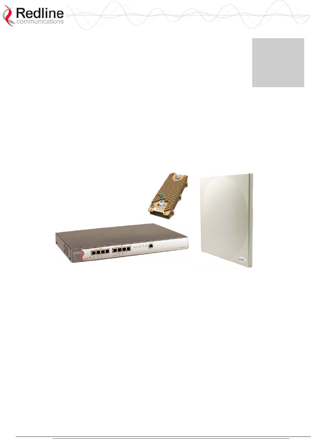
The AN-30e system consists of an indoor terminal and outdoor radio (transceiver and
antenna).
Figure 1: AN-30e System: Terminal, Transceiver, and Antenna
A point-to-point (PTP) link is comprised of an AN-30e system configured as a sector
controller (master-mode) and a single AN-30e configured as a subscriber station. The
sector controller establishes a bi-directional data link with the subscriber station. The
subscriber receives and sends data under the control of the sector controller.
AN-30e
user manual
70-00035-01 Proprietary Redline Communications © 2004 November 2004
Page 16 of 104
2.1 Terms Used in this Manual
The following terms are used in this manual:
Table 1: Terms
Term Description
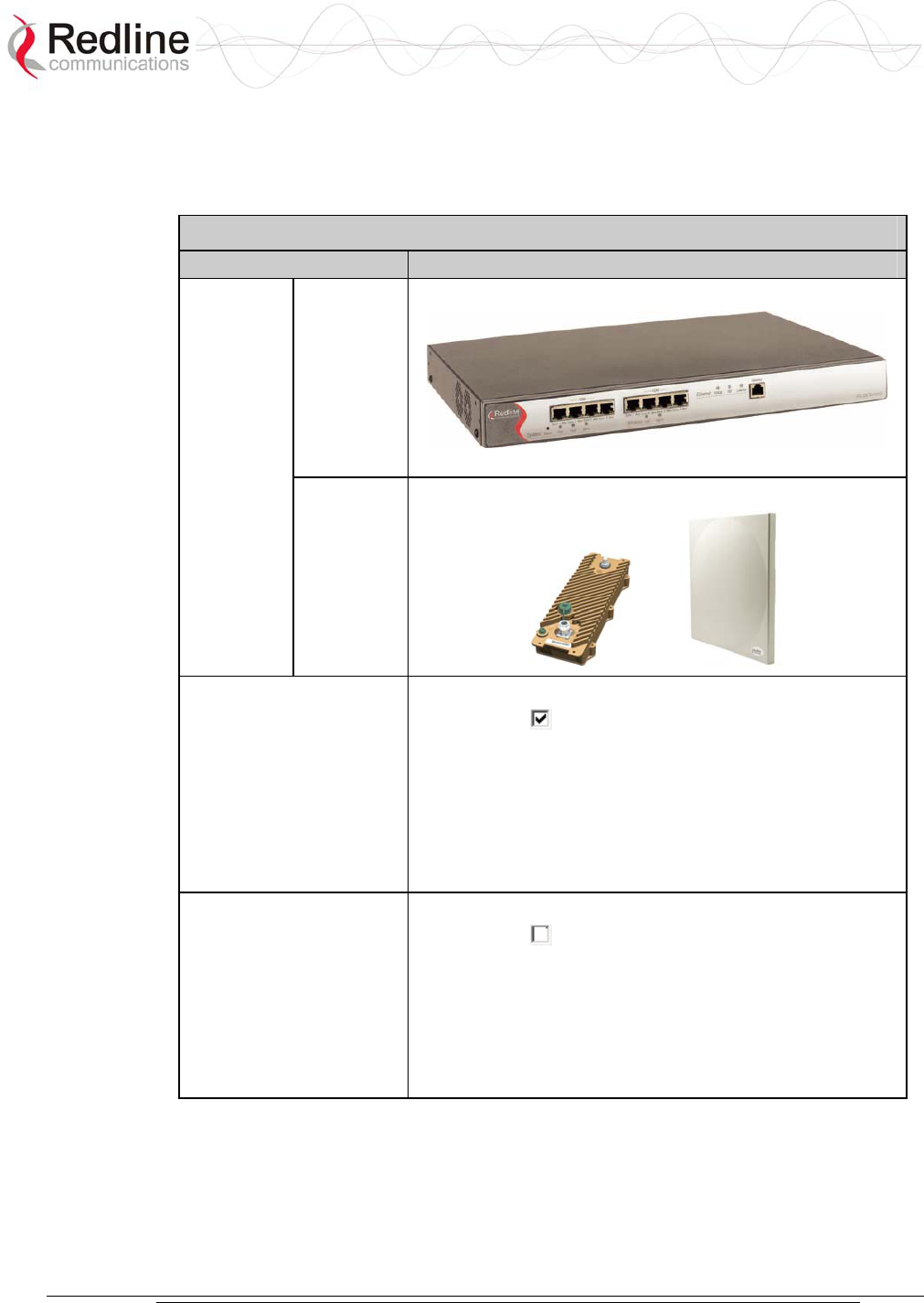
AN-30e
terminal
Indoor unit
AN-30e
System
AN-30e
Radio
Transceiver + Antenna
Sector Controller
Master-mode
The terminal is configured as a sector controller (base
station). This system controls the wireless link polling and
transmission opportunities. The sector controller is
connected to customer Ethernet network and establishes a
bi-directional data link over-the-air with one or more
subscriber AN-30e systems.
Subscriber Station
Master-mode
The terminal configured as a subscriber station.
The subscriber is connected to the customer Ethernet
network, and both receives and sends data over-the-air
under control of the sector controller.
AN-30e
user manual
70-00035-01 Proprietary Redline Communications © 2004 November 2004
Page 17 of 104
Chapter
3
3
3
S
Sy
ys
st
te
em
m
O
Ov
ve
er
rv
vi
ie
ew
w
The AN-30e is a high-performance, high-speed wireless Ethernet bridge terminal
providing a scalable multi-service platform from a common equipment infrastructure
and management system. The AN-30e system is a Class A digital device for use in a
commercial, industrial or business environment.
The AN-30e system operates in the 5.4 GHz to 5.8 GHz band and includes advanced
technologies to address inter-cell interference. The AN-30e can be equipped with a
narrow beam antenna to provide high directivity for long-range operations in clear
line of sight (LOS) conditions. The system also delivers enhanced security through a
proprietary over-the-air encryption scheme.
Figure 2: AN-30e terminal
The AN-30e system is equipped with dynamic frequency selection (DFS) to detect
interference from other devices using the same frequency and automatically take a
pre- selected action, such as disable transmission or relocate transmission to
alternative frequency. The system also includes an automatic transmitter power
control (ATPC) function to automatically adjust the transmit level of subscribers to
match a selected RSSI value.
The AN-30e PTP system operates using one end of the link designated as the sector
controller (master) and the other end of the link as subscriber station. The sector
controller MAC utilizes a request/grant polling mechanism to determine when the
subscriber station requires bandwidth. When the subscriber station requests
bandwidth, the sector controller MAC allocates uplink time slots based on current
availability.
AN-30e
user manual
70-00035-01 Proprietary Redline Communications © 2004 November 2004
Page 18 of 104
3.1 TDM over Wireless
The AN-30e terminal supports simultaneous transport of up to eight full or fractional
rate E1/T1 lines. Optional high speed Ethernet access is also available to operate
concurrently with the TDM transport.
3.1.1 Theory of Operation
TDM transport is achieved through a form of circuit emulation specifically optimized
for wireless operation. The TDM signals are received by the AN-30e at the serial port
interfaces, sampled, and encapsulated within an Ethernet frame structure. The
Ethernet encapsulated traffic is transported over the wireless link to another AN-30e
where the TDM traffic is reconstructed by reversing the encapsulation process and re-
clocking the TDM traffic.
Regular CAS signaling is passed transparently in the TDM traffic, and is not
monitored by the AN-30e system. For fractionalized E1, at least one bundle on each
port must include the signaling channel to support this pass-through feature.
3.1.2 TDM Configuration
TDM signals on the RJ-48/BNC interfaces are sampled and the data is encapsulated
into Ethernet frames. This data is transmitted over the wireless link where the TDM
traffic and clock synchronization are reconstructed.
The TDM signals are transmitted in up to eight separate bundles. Each bundle may
include data from up to 32 consecutive timeslots, allowing full or fractional transport.
Each bundle may be assigned a separate AN-30e system destination address.
Fractional nx64 services allow the user to conserve bandwidth by sending only a sub-
set of channels (time-slots) to transport over the wireless link. The TDM channels can
also be mapped to different timeslots/serial ports at subscriber AN-30e terminals,
performing a cross-connect function over the air.
Figure 3: AN-30e Ethernet/TDM Transport

AN-30e
user manual
70-00035-01 Proprietary Redline Communications © 2004 November 2004
Page 19 of 104
Jitter
Variable transmission delays are introduced by the simultaneous transmission of
TDM and data traffic. To insure proper timing of reconstructed TDM traffic, the
subscriber terminal employs a jitter buffer. The jitter buffer is an industry standard
method used to compensate for delay variations that occur during transport of the
encapsulated Ethernet traffic.
Latency
To achieve the lowest possible latency, the AN-30e must be used exclusively for
TDM transport and the Ethernet data port must be inactive. Use of the Ethernet port
for in-band management or user data transport requires higher jitter buffer settings
proportional to the level of non-TDM throughput.
QoS
The AN-30e uses IEEE 802.1p to enforce QoS for TDM based applications such as
mobility backhaul and enterprise PBX traffic. Traffic can be assigned to high or low
priority queues. Ethernet packets are examined and queued according to the priority
tag. All TDM traffic is assigned to be high priority.
Flow Control
The IEEE 802.3x standard provides a flow control method for improved traffic
shaping. When the AN-30e terminal detects a high traffic condition, or the wireless
throughput is decreased, an IEEE 802.3x pause control frame is sent to the upstream
Ethernet device. This control command inhibits the Ethernet device from transmitting
additional regular data packets for the period specified in the pause control frame, or
another pause control frame is received with the time set to zero. Only flow control
packets can be transmitted from a paused device.
Deployment
A typical PTP configuration may be used for backhauling full rate E1/T1 lines in a
mobility application. All traffic is terminated at the same endpoints.
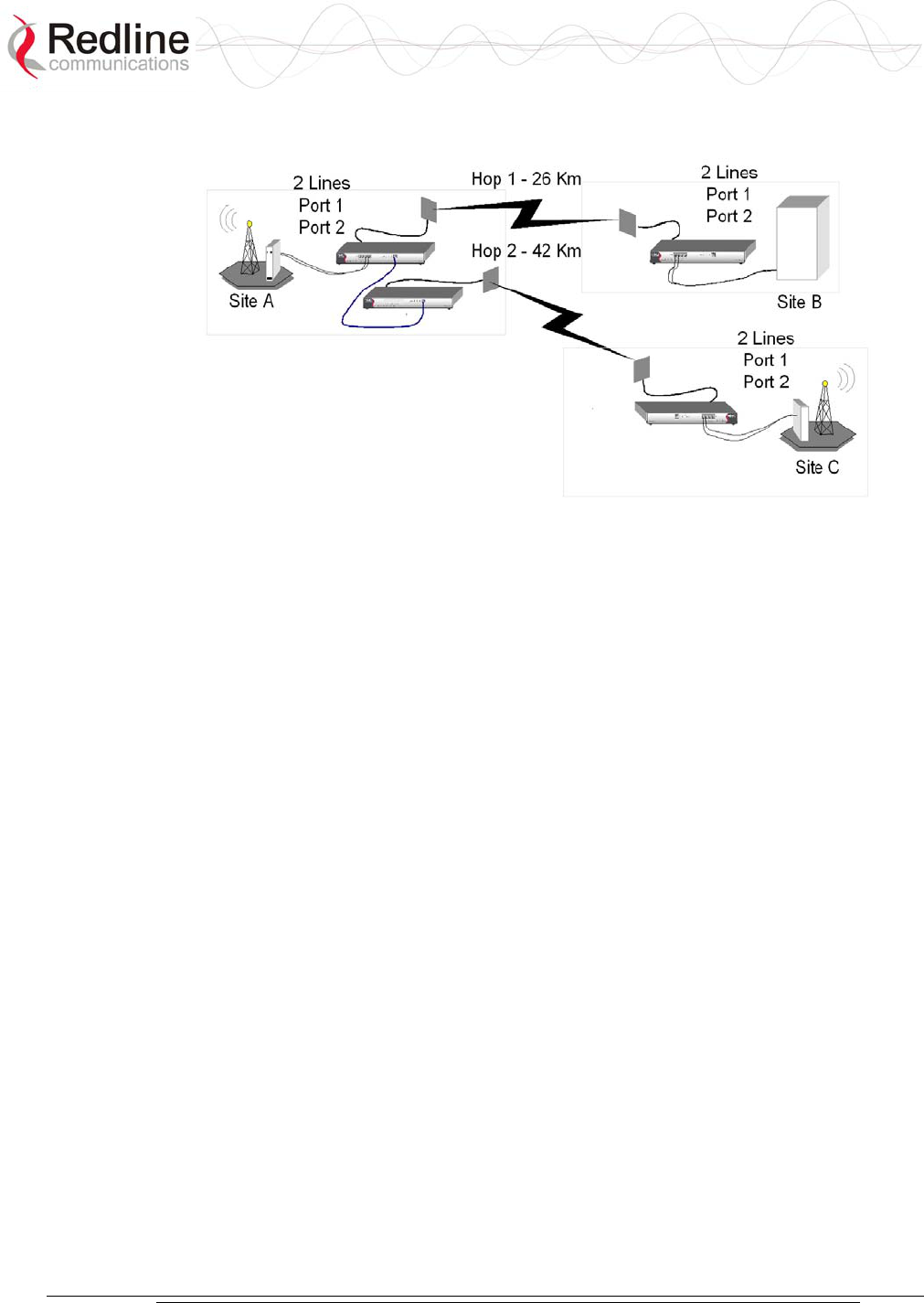
The AN-30e can also be deployed in a cascaded multi-hop configuration with drop
and insert points. In the following multi-hop example, the TDM data is encoded and
sent over the wireless link to other AN-30e systems. Data received on the wireless
link may be directed to a local TDM port for decoding and/or routed to the Ethernet
port connected to another Redline system for retransmission on a separate wireless
link.
AN-30e
user manual
70-00035-01 Proprietary Redline Communications © 2004 November 2004
Page 20 of 104
Figure 4: AN-30e Multi-Hop Deployment Example

AN-30e
user manual
70-00035-01 Proprietary Redline Communications © 2004 November 2004
Page 21 of 104
Chapter
4
4
4
P
Ph
hy
ys
si
ic
ca
al
l
D
De
es
sc
cr
ri
ip
pt
ti
io
on
n
Important: The AN-30e system must be installed by a professional installer who is
familiar with both data network issues and RF installations including grounding and
lightning protection.
4.1 Quick Install Guide
Experienced installers may refer to a copy of the guide "Redline AN-30e Quick
Install Guide" provided on AN-30e CD-ROM. This guide provides instructions for
basic system configuration and aligning the antennas.
Additional detailed installation information is available in the manual titled
"Installation Guidelines for Redline AN-30e PTP Systems" also provided on AN-30e
CD-ROM. This guide provides instructions for site planning and installation
including weatherproofing and antenna alignment.
4.2 Unpacking the AN-30e
The system comes packaged with the following items:
- Quality inspection report
- Quick start installation guide
- Documentation CD-ROM
- AN-30e terminal and mounting brackets
- T-54, T-58, or T-58e transceiver
- Antenna and mounting bracket
- RF and IF cables
- AC and/or DC power cables
- Optional items (such as lightning protectors)
A complete list of items included in the system is available on the packing list
included with the system.

AN-30e
user manual
70-00035-01 Proprietary Redline Communications © 2004 November 2004
Page 22 of 104
4.3 AN-30e Terminal
The front panel includes the Ethernet port, the TDM ports, and three groups of LED
indicators: System, Wireless, and Ethernet. The rear of the terminal includes the
power supply connections, the IF port, the serial console port, and a BNC connector
for the time synchronization signal (future release).
4.3.1 Mounting
The terminal can be freestanding on a flat surface, or mounted into a standard 19-inch
equipment rack.
4.3.2 Power Supply
The AN-30e power supply connections are provided on the rear of the chassis.
Separate connections are provided for each power supply.
Grounding Connection
A ground connection terminal is located on the back of the AN-30e system. Correct
grounding is very important for safe operation of wireless equipment. Refer to the
installation section for additional information.
System Fuse
Removable fuses located at the rear of the terminal protect the system power inputs.
Refer to section 7.5: Replacing System Fuse on page 75 for additional information.
4.3.3 Time Synchronization Port
The AN-30e has one BNC input on the rear panel for time synchronization. This port
accepts a standard IRIG-B signal (1 pps) from a GPS satellite clock. This port is
currently disabled and is enabled in a future software release.
4.3.4 Wireless Section
This section describes the wireless port and LEDs.
IF Port (Radio Control)
The terminal has a female F-type connector (rear of chassis) for interconnection with
the system radio.
The IF cable carries the following signals between the terminal and the radio:
- OFDM IF signal at 815 MHz
- Local Oscillator (LO) signal at 2.5 GHz
- 24 Volt DC voltage for the transceiver electronics
- Control signal between IDU and ODU
AN-30e
user manual
70-00035-01 Proprietary Redline Communications © 2004 November 2004
Page 23 of 104
Wireless LEDs
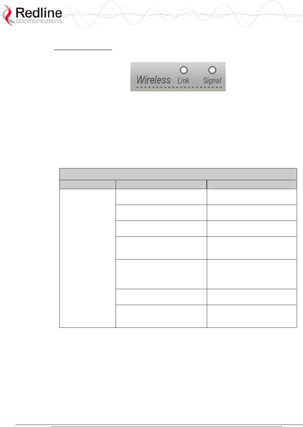
There are two Link and Signal indicator LEDs on the front panel.
Figure 5: Front Panel - Wireless LEDs
Link LED
The Wireless Link LED lights solid green when the wireless link is established.
When the Link LED is off, it is an indication there is a problem with either the
terminal link, radio, or with the actual propagation path itself. Check the RF Status
parameters in the System Status screen. The following table lists some of the potential
causes.
Table 2: Wireless Link Diagnostics
Symptom Possible Problem Solution
Subscriber terminal is not on or
is malfunctioning.
Verify operation of subscriber
terminal.
The propagation path is
blocked.
Clear path or re-locate
antennas.
The transceiver is mal-
functioning.
Repair or replace transceiver
Antenna has moved and is no
longer aligned with subscriber
terminal.
Re-align the antenna.
Cable between transceiver and
antenna or between transceiver
and terminal not properly
connected.
Properly secure cables.
Power not getting to the
transceiver from the terminal.
Repair or replace terminal.
No wireless link
(Link LED does
not illuminate)
Receiver and transmitter have
been set to different RF
channels.
Make sure both terminals are
operating on the same RF
channel.
Signal LED
When Adaptive Modulation is disabled, the Wireless Signal LED lights solid green if
the system is operating at a BER of less than 1 x 10e-9. The LED flashes if the
number of errors exceeds this limit. If the wireless link becomes very poor, the LED
turns off.
When Adaptive Modulation is enabled, the Wireless Signal LED lights solid green if
the system is operating at a rate equal to or higher than the configured Uncoded Burst
Rate. The LED flashes when the system is operating at a modulation scheme with a
AN-30e
user manual
70-00035-01 Proprietary Redline Communications © 2004 November 2004
Page 24 of 104
lower maximum burst rate. The Signal LED turns off if the system cannot maintain a
link using the lowest modulation scheme.
Intermittent flashing may not indicate a serious problem. Refer to the following table
for additional information.
Table 3: Wireless Signal Diagnostics
Symptom Possible Problem Solution
Obstructions in the
propagation path causing
signal degradation.
Try to remove obstacles or re-
locate antenna.
Antenna moved, due to high
winds.
Re-align the antenna.
Weak RF Link
(Signal LED
flashes)
Poor cable connection
between transceiver and
antenna.
Repair or replace the RF cable.
4.3.5 Ethernet Section
This section describes the terminal Ethernet port and LEDs.
Ethernet Data Port
The Ethernet Data port is always enabled. The port can be set for automatic selection
or set manually to operate in full duplex or half duplex mode at 10 Mbps or 100
Mbps.
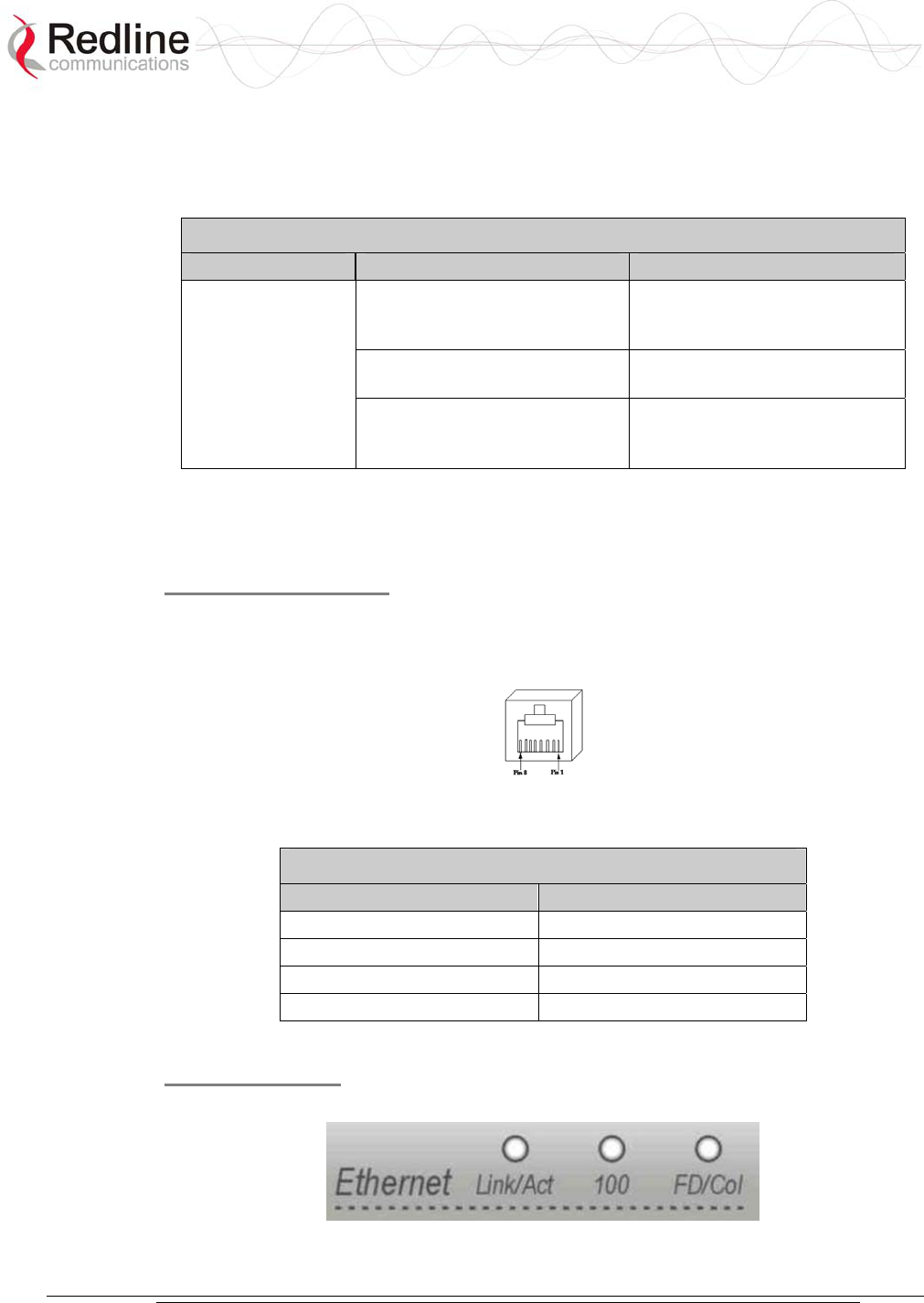
Figure 6: RJ-45 Jack Face
Table 4: terminal LAN Ethernet Port Pinout
Jack Pin Function
1 Rx +
2 Rx -
3 Tx +
6 Tx -
Warning: Connecting a telephone cable to the Ethernet interface will damage the terminal.
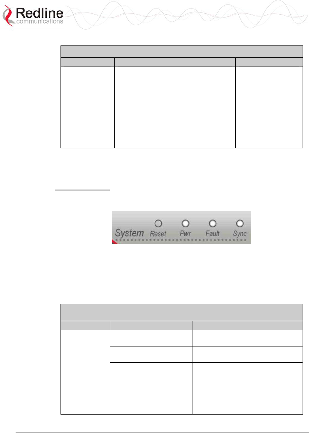
Ethernet LEDs
The Ethernet portion of the front panel display has three LEDs.
Figure 7: Front Panel: Ethernet LEDs

AN-30e
user manual
70-00035-01 Proprietary Redline Communications © 2004 November 2004
Page 25 of 104
Link/Act LED
The Link/Act LED lights solid green when the Local Area Network (LAN)
connection is established, and there is no traffic. The Link LED flashes when the
Local Area Network (LAN) connection is established and traffic is detected.
The Link/Act LED is functioning properly and traffic is detected. If the LED is off, it
may indicate one of the problems listed in the following table:
Table 5: Ethernet Link/Act Diagnostics
Symptom Possible Problem Solution
Poor cable connection
between terminal and
computer/server or between
terminal and switch/router.
Carefully check all cable
connections.
Wrong type of Ethernet cable
between terminal LAN port
and host.
If the terminal LAN port is
connected to a host, then
ensure a straight-through cable
is used. Otherwise, to connect
the terminal to a switch or
router, ensure a crossover
cable is used.
The auxiliary Network
equipment may be
malfunctioning.
Repair or replace faulty
terminals.
No Ethernet Link
(Link/Act LED off)
Processor malfunction. Try short reset or long reset.
100 LED
The 100 LED lights solid green when the Ethernet port is operating at 100 Mb/s. The
LED is not illuminated when the port is operating in 10 Mb/s mode.
Table 6: Ethernet 100 Diagnostics
Symptom Possible Problem Solution
Ethernet connection manually
set for 10Base-T operation.
Change Ethernet Mode setting
to Auto or 100 in the System
Configuration web screen.
Ethernet Link 100
LED off
The connected Ethernet
device may be operating at
10Base-T.
If the terminal LAN port is
connected to a host computer
or server operating at 10Base-
T, you may have to change the
settings for that device.
FD/Col LED
The FD/Col LED lights solid green when the LAN connection is operating in Full
Duplex mode and flashes when collisions are detected on the Ethernet port.
When connected to a hub, it is typical for packet collisions to occur intermittently. On
a Half-Duplex link, there are collisions. Some causes are listed in the following table.
AN-30e
user manual
70-00035-01 Proprietary Redline Communications © 2004 November 2004
Page 26 of 104
Table 7: Ethernet Collision Diagnostics
Symptom Possible Problem Solution
Collisions are normal for Half Duplex
links. However, if the terminal is
connected to is not configured for auto-
negotiation, but manually set for Full
Duplex, the terminal is not able to
negotiate this mode and stays set to Half
Duplex. This results in CRC errors on the
network device port.
Change the
configuration from
hard coded Full
Duplex to auto-
negotiation
Link Collision
(FD/Col LED
flashes)
Incompatible Ethernet port speed. Confirm speed and
duplex mode of
devices.
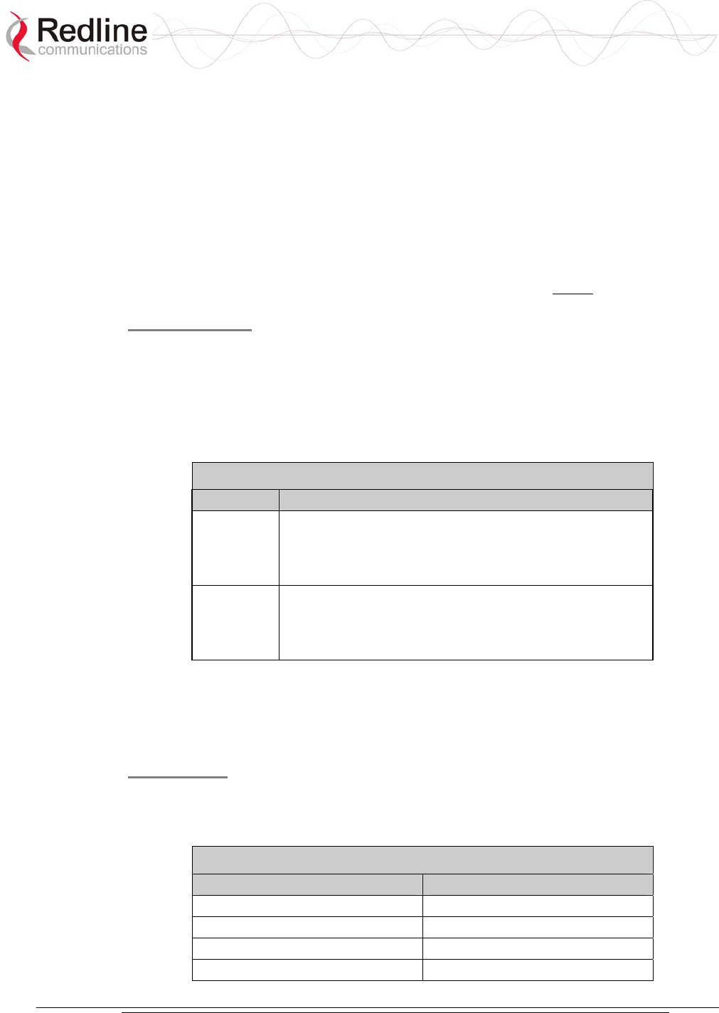
4.3.6 System Section
This section describes other general features of the front panel.
System LEDs
The System LEDs indicate power supply status, system faults, and synchronization
status.
Figure 8: Front Panel: Reset Switch and System LEDs
Pwr LED
The Pwr LED lights solid green when the AC and/or DC power is properly applied to
the terminal. The Pwr light does not illuminate if there is an internal power supply
failure, if the power cables are disconnected, or the fuse is blown.
Table 8: System Power Diagnostics
Symptom Possible Problem Solution
On/Off switch in Off position Turn power switch on at back of
terminal.
Fuse blown Replace fuse (spares are provided).
See section 7 for details.
Power cord disconnected Securely connect cord to terminal and
outlet
Pwr LED does
not illuminate
One of the dual power
supplies is defective or
powered off (redundant
configuration).
Schedule maintenance to replace
defective power supply.
AN-30e
user manual
70-00035-01 Proprietary Redline Communications © 2004 November 2004
Page 27 of 104
Fault LED
The Fault LED lights solid red to indicate a serious problem with the system software
or hardware.
Check the IF cable for loose connections. Also, refer to the System Logs screen and
RF Status codes for additional information about the problem. Alternatively, if a
short-reset or long-reset does not resolve the problem, contact your local
representative.
Sync LED
The Sync LED lights solid green when the AN-30e is synchronized with an external
clock. The Sync port is currently disabled, and is enabled in a future software release.
Reset Switch
The reset button is recessed in the front panel of the terminal. To operate the switch,
use a small narrow object (i.e., paper clip) to depress the switch.
Depressing the reset button for less than five seconds activates a short-reset
(equivalent to cycling power on the terminal). Depressing the reset button for longer
than five seconds activates a long-reset and some parameters are changed to the
factory default settings. Refer to the following table for details.
Table 9: Front Panel Reset Switch
Operation Result
Depress
switch less
than 5
seconds.
Statistical values are reset.
A short reset may also be activated remotely from the
Web maintenance tool by clicking on the System Reset
button at the bottom of the System Configuration screen.
Depress
switch
longer than
5 seconds.
Reload the factory default configuration for the following
settings: IP Address, IP Subnet Mask, Channel, System
Name, Username, and Password.
Refer to section 69: Factory Default Settings on page 69.
4.3.7 The TDM Interface
The TDM interface includes TDM ports to connect the terminal to a PBX or other
TDM device. Each port has Alarm and Sync indicator LEDs.
TDM Ports
The TDM interface is equipped with eight RJ-48 ports. Entering the product options
key selects the number of active ports. The following table lists the pinout for the
TDM interface.
Table 10: TDM Port RJ-48 Pinout
Jack Pin Function
1 Rx Data (R1)
2 Rx Data (T1)
4 Tx Data (R2)
5 Tx Data (T2)
AN-30e
user manual
70-00035-01 Proprietary Redline Communications © 2004 November 2004
Page 28 of 104
Interfacing from the RJ-48 TDM port to a CPE device (DSU/CSU or PBX) requires
the use of a cross over cable, constructed using 24 AWG Cat 5 wiring. These cable
connections are listed in the following table.
Table 11: TDM RJ-48 CPE Connection Cable
Connector A Connector B
1 4
2 5
4 1
5 2
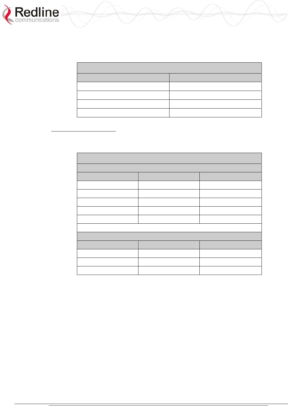
TDM Alarm LEDs
Each serial interface port has Alarm and Sync indicator LEDs mounted on the RJ-48
socket. These LEDs indicate the following alarm conditions on the TDM circuits:
Table 12: TDM Port Alarm Condition LEDs
Single Alarm Conditions
Alarm Sync LED (Green) Alarm LED (Amber)
No Alarm On Off
LOS Off On
LFA Blink On
AIS Off Off
RAI On Flickering
Multiple Alarm Conditions
Multiple Alarm Conditions
Alarm Sync LED (Green) Alarm LED (Amber)
AIS + LFA Blink Off
AIS + RAI Off Flickering
RAI + LFA Flickering Flickering
Alarm conditions detected by the terminal are sent to the customer equipment using
the TDM signaling channels. Refer to the following examples of AN-30e system
behavior for additional information.
Example 1: Loss of Tx to a subscriber CPE
Loss of Tx to a subscriber CPE would result in RAI from the CPE to the
subscriber terminal. This signal is annunciated using the LEDs at the subscriber
terminal, and sent to the local terminal and the customer central office equipment.
Example 2: Loss of Rx from a subscriber CPE
Loss of Rx from a subscriber CPE would result in LOS being annunciated using
the LEDs at the subscriber terminal, and AIS being sent to the local terminal and
customer central office equipment. The RAI issued by the central office
equipment would be registered at each of the terminals and propagated all the way
back to the subscriber CPE.
AN-30e
user manual
70-00035-01 Proprietary Redline Communications © 2004 November 2004
Page 29 of 104
4.4 System Radio
4.4.1 Transceiver
The radio transceiver is housed in an aluminum alloy case. The connectors are listed
in the following sections.
Figure 9: Transceiver
4.4.2 IF Port (Radio Control)
The transceiver IF port (female F-type connector) is for communications with the
terminal. This port is connected with the terminal through coaxial cable.
4.4.3 RF Connector
The transceiver RF port (female N-type connector) is for sending/receiving the RF
signal to/from the antenna. A short coaxial cable is provided to connect the
transceiver to the antenna.
4.4.4 Alignment Pin and Audible Signal
For basic alignment using the received signal, an alignment buzzer (intermittent tone
sweep generator) and a voltage pin is available on the ODU transceivers. The faster
the repetition rate of the buzzer displays the stronger the signal received from the
remote end.
You can also adjust for a voltage peak using a DC voltmeter connected to the
alignment voltage pin on the ODUs (if equipped). Use of either the buzzer or
alignment pin is enabled using the software interface. Use the Web interface field
General Antenna Alignment to enable and disable this feature (Refer to section 5.5:
Configure System on page 38).
4.4.5 Antenna
The same type of antenna can be used for both ends of any PTP deployment. Refer to
section 8.3: Antenna and Power Specifications on page 81 for descriptions and
specifications of available antennas

AN-30e
user manual
70-00035-01 Proprietary Redline Communications © 2004 November 2004
Page 30 of 104
Figure 10: One-Foot Flat Antenna
The transceiver RF port (female N-type connector) is for sending/receiving the RF
signal to/from the transceiver. A short coaxial cable is provided to connect the
antenna to the transceiver.
4.4.6 Antenna Mounting Bracket
A vertical mount bracket is provided with the system. The vertical mount bracket can
accommodate 1 ¾" to 4 ½" (4.45 cm to 11.45 cm) OD masts found on many
commercial tower installations.
AN-30e
user manual
70-00035-01 Proprietary Redline Communications © 2004 November 2004
Page 31 of 104
Chapter
5
5
5
U
Us
si
in
ng
g
t
th
he
e
W
We
eb
b
I
In
nt
te
er
rf
fa
ac
ce
e
This section describes the procedures for configuring and operating the terminal via
the web interface.
Communication with the terminal is achieved over the Ethernet port using Hypertext
Transfer Protocol (HTTP) over a TCP/IP connection. This offers the advantage of
allowing the operator to access and control the terminal remotely from any
geographical location having access to the Internet.
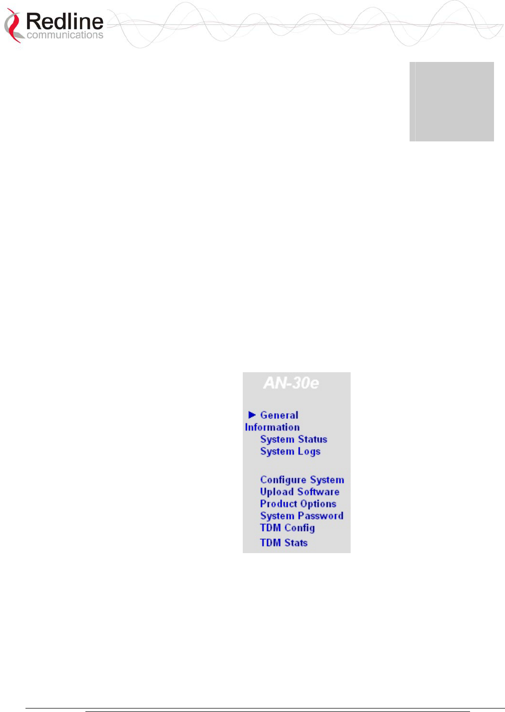
5.1 System Menu
When the user is successfully logged in, the General information page is displayed.
On the left is a menu of all available pages. The operator can point and click on any
of the blue text lines in the menu to display the selected page.
Figure 11: On-Screen Menu
The administrator (admin) has unrestricted access to all screens. All other users have
restricted access. See the following table for details.
AN-30e
user manual
70-00035-01 Proprietary Redline Communications © 2004 November 2004
Page 32 of 104
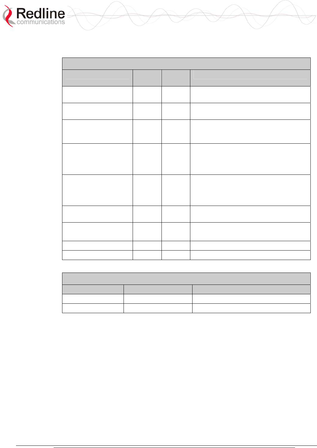
Table 13: Web Screens
Screen Admin
Access
User
Access
Description
General Information X X View general system identification and
configuration settings.
System Status X X View system information, Ethernet
statistics, and wireless statistics.
System Logs X X View the last forty system activity and
error messages recorded by the
terminal.
Configure System X View and adjust configuration settings
for general system identification, IP
address, management functions, and
wireless.
Upload Software X Upgrade the existing software load of
the terminal with new software stored in
a binary file on the server or host
computer.
Product Options X Upgrade the terminal with custom
options.
System Password
X X Change your login password.
TDM Config X TDM Configuration
TDM Stats X TDM Statistics
Table 14: Default System Users
Username Default Password Description
admin admin Access to all screens
user user Access restricted to monitoring screens.
AN-30e
user manual
70-00035-01 Proprietary Redline Communications © 2004 November 2004
Page 33 of 104
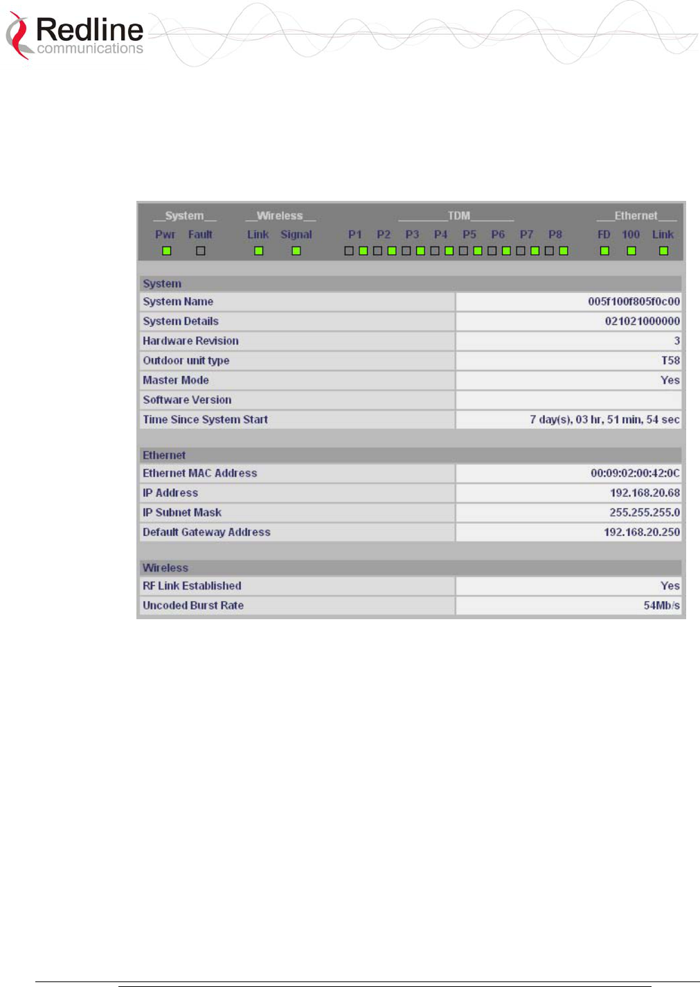
5.2 General Information
Click on General Information to view general system information, Ethernet LAN
address information, and wireless settings. This page includes a view of the terminal
front panel LEDs.
Figure 12: General Information Screen
5.2.1 System
System Name: Displays the user-specified name for the local terminal.
System Details: Displays the user-specified information such as location, telephone
number, and/or contact number.
Hardware Revision: Displays the detected hardware revision level for this terminal.
Outdoor Unit Type: Displays the detected transceiver model number.
Master-mode: Displays the user-specified operating mode of the terminal.
Yes: System is configured as a sector controller.
No: System is configured as a subscriber station.
Software Version: Displays the detected software version in use.
Time Since System Start: Displays the time [dd/hh/mm/ss] since the system started.

AN-30e
user manual
70-00035-01 Proprietary Redline Communications © 2004 November 2004
Page 34 of 104
5.2.2 Ethernet:
Ethernet MAC Address: Displays the unique Ethernet address detected for this
terminal.
IP Address: Displays the user-specified IP address of the terminal.
IP Subnet Mask: Displays the user-specified subnet for this terminal.
Default Gateway Address: Displays the user-specified IP address of the default
router/gateway on the local Ethernet segment.
5.2.3 Wireless:
RF Link Established: Displays the status of the wireless link.
Yes - RF link is established.
No - RF link has not been established.
Uncoded Burst Rate: Displays the measured uncoded burst rate for the link.
AN-30e
user manual
70-00035-01 Proprietary Redline Communications © 2004 November 2004
Page 35 of 104
5.3 System Status
Click System Status in the menu to view system information and Ethernet and
wireless statistics.
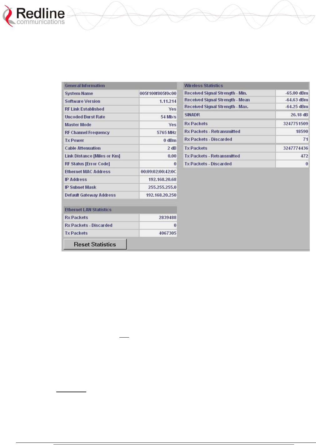
Figure 13: System Status Screen
5.3.1 General Information:
System Name: Displays the user-specified name for the local terminal.
Software Version: Displays the detected software version in use.
RF Link Established: Displays the status of the wireless link.
Yes - RF link is established.
No - RF link has not been established.
Uncoded Burst Rate [Mb/s]: Displays the uncoded burst rate for the link.
Master-mode: Displays the user-specified operating mode of the terminal.
Yes: System is configured as a sector controller.
No: System is configured as a subscriber station.
Important: Only one terminal must be designated Master on each wireless link.
RF Channel Frequency: Displays the user-specified channel center frequency.
Tx Power: Displays the user-specified transmit power level.
Cable Attenuation: Displays the measured attenuation level for the 800 MHz signal
over the IF cable.

AN-30e
user manual
70-00035-01 Proprietary Redline Communications © 2004 November 2004
Page 36 of 104
Link Distance [Miles or Km]: Displays the user-specified distance between the two
ends of the wireless link.
RF Status [Error Code]: Displays an error code indicating the status of the system
RF components. Code 'zero' indicates normal operation. See the RF Status Error Code
Table 33: RF Status Error Codes on page 72 for details.
Ethernet MAC Address: Displays the unique Ethernet address of this terminal.
IP Address: Displays the user-specified IP address of this terminal.
IP Subnet Mask: Displays the user-specified subnet mask.
Default Gateway Address: Displays the user-specified IP address of the default
router/gateway on the local Ethernet segment.
5.3.2 Ethernet LAN Statistics:
Rx packets: Displays the number of non-errored packets received.
Rx packets - Discarded: Displays the number of errored packets received.
Tx Packets: Displays the total number of Ethernet packets transmitted.
5.3.3 Wireless Statistics:
Received Signal Strength: Min: Displays the minimum received signal strength
measured since the last screen refresh.
Received Signal Strength: Mean: Displays the average received signal strength,
computed since the last screen refresh.
Received Signal Strength: Max: Displays the maximum received signal strength
measured since the last screen refresh.
SINADR: Displays the average signal to interference, noise and distortion ratio
measured since the last screen refresh.
Rx Packets: Displays the total number of wireless packets received over the air.
Rx Packets: Retransmitted: Displays the number of wireless packets retransmitted over
the air.
Rx Packets: Discarded: Displays the number of wireless packets received over the air
with errors due to degradation in the RF link.
Tx Packets: Displays the number of wireless packets (including Ethernet frames and
error correction bytes) successfully transmitted over the air.
Tx Packets: Retransmitted: Displays the number of wireless packets retransmitted over
the air. The retransmission scheme is based on the Automatic Repeat Request (ARQ)
algorithm that detects when packets are lost, and makes a request to the MAC scheduler
to repeat transmission of the lost packets.
Tx Packets: Discarded: Displays the number of transmitted wireless packets discarded
by the subscriber terminal, due to degradation in the RF link.
5.3.4 Statistics Control Button:
Reset Statistics: Click this button to zero all counters.

AN-30e
user manual
70-00035-01 Proprietary Redline Communications © 2004 November 2004
Page 37 of 104
5.4 System Logs
Click System Logs in the menu to view the last forty system activity and error
messages recorded by the terminal.
Figure 14: System Logs Screen
The logs also indicate if the following transactions were successfully completed:
Save Configuration: Configuration screen.
Upload: Upload Software screen.
Change Password: System Password screen.
Send Options Key: AN-30e Options screen
Refer to section 7.4: System Error Log Messages on page 73 for the full list of event
messages.
AN-30e
user manual
70-00035-01 Proprietary Redline Communications © 2004 November 2004
Page 38 of 104
5.5 Configure System
Click Configure System in the menu to view and adjust configuration settings for
general system identification, Ethernet, and the wireless interface.
Important: Ensure that all fields on the System Configuration Screen are filled out
properly for local and subscriber terminals. Errors in these fields can result in the
inability to establish a communication link. Please read carefully to ensure a quick,
trouble-free deployment.
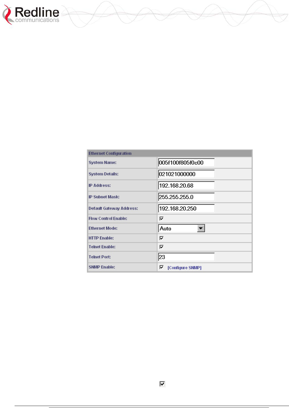
5.5.1 Ethernet Configuration:
The IP address information must be set properly before the terminal is connected to
the local Ethernet network, otherwise, address conflicts may occur with other devices
on the network.
Figure 15: System Configuration Screen - Ethernet Settings
System Name: User-specified name for the local terminal. Enter any combination of
up to 20 letters and numbers.
System Details: User-specified system description for the local terminal. Enter any
combination of up to 20 letters and numbers.
IP address: User-specified IP address for this terminal. The factory default address is
192.168.25.2.
IP Subnet Mask: User-specified IP subnet mask. The factory default mask is
255.255.255.0 (Class C subnet).
Default Gateway Address: User-specified IP address of the default gateway on the
local Ethernet segment.
Flow Control Enable: Check this box to enable flow control on the terminal.

AN-30e
user manual
70-00035-01 Proprietary Redline Communications © 2004 November 2004
Page 39 of 104
When you enable the Flow Control option, the AN-50e tests the p (priority) setting
for any 802.1Q packet received on the Ethernet port. If the packet priority is set to a
value of zero to three, the data is assigned to a low priority queue. If the packet
priority is set to a value of 4-7, the data is assigned to the high priority queue.
All high priority traffic is transmitted before any low priority traffic is transmitted.
This ensures that high priority traffic (such as VoIP packets) receives priority over
lower priority data-only traffic.
Ethernet Mode: Select the operating mode of the Ethernet port.
Auto - Auto-negotiate the speed connection speed.
10 Mbps HD - Operate at 10Base-T half duplex only.
10 Mbps FD - Operate at 10Base-T full duplex only.
100 Mbps HD - Operate at 100Base-T half duplex only.
100 Mbps FD - Operate at 100Base-T full duplex only.
HTTP Server Enable: Check this box to enable the HTTP (Web) interface.
If this setting is disabled -- this screen is not available. Refer to the CLI commands
section in the Appendix for methods to enable the HTTP interface using the Telnet
interface or the console port.
Telnet Enable: Check this box to enable Telnet sessions. Refer to the CLI
commands in the Appendix.
Telnet Port: Enter the Telnet port address. The default Telnet port is 23. The port can
be changed to any other number between 23 and 65,000, excluding port 80.
SNMP Enable: Check this box to enable the Simple Network Management
Protocol (SNMP) agent. When this item is checked, clicking on the blue text
[Configure SNMP] beside the checkbox displays the SNMP Configuration screen.
See section 0: SNMP Settings on page 39 for additional information on setting up
SNMP for the AN-30e.
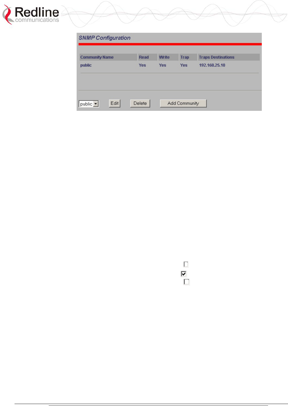
SNMP Settings Screen
Click Configure SNMP (blue text) on the System Configuration screen to view and
edit the SNMP settings. The blue text appears when the SNMP Enable box is
checked.
Figure 16: System Configuration Screen - SNMP Access
The SNMP Configuration screen displays a list of the current communities. The
control buttons can be used to add, edit, or delete communities.
AN-30e
user manual
70-00035-01 Proprietary Redline Communications © 2004 November 2004
Page 40 of 104
Figure 17: SNMP Configuration Screen
SNMP Configuration: The list of defined communities is displayed in the
Community Name table.
Edit: Select a community from the pull down menu and click the Edit button to
modify an existing community. The Community Configuration/Trap Configuration
screen is displayed.
Delete: Select the community from the pull down menu (bottom left of screen) and
then click the Delete button to delete that community. Note that it is not possible to
delete the public SNMP community, but the access level can be changed.
Add Community: Click the Add Community button to add a new community. The
Community Configuration/Trap Configuration screen is displayed.
Add Community: To add a new community, click Add Community button. The
Community Configuration/Trap Configuration screen is displayed.
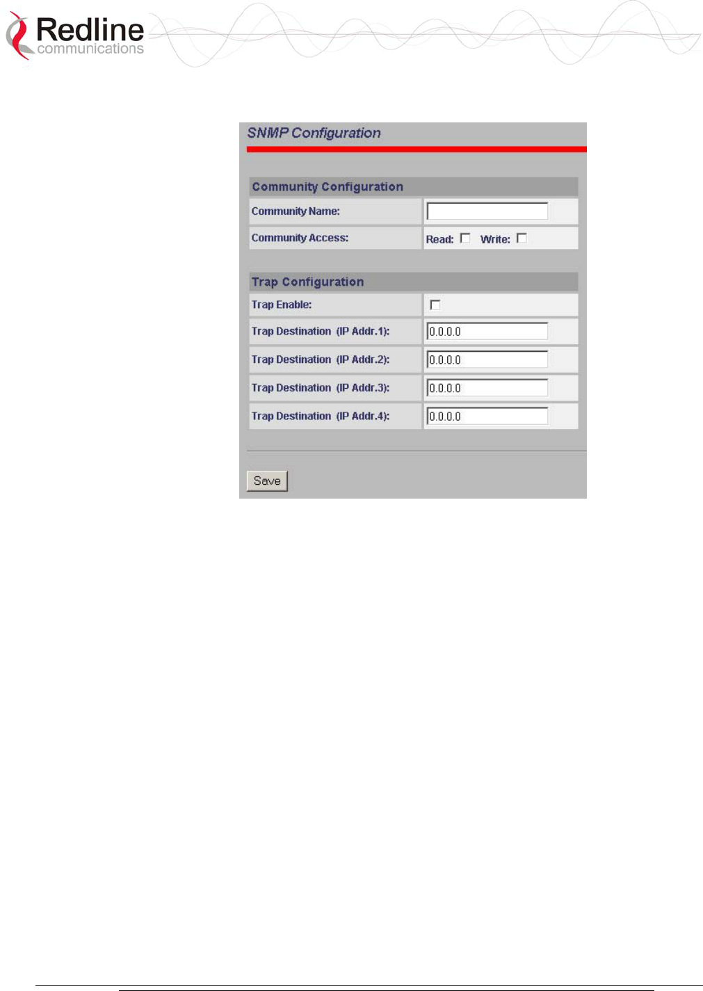
Community Configuration:
Community Name: The SNMP community name.
Community Access - Read: Check the Read box to grant read access permission to
members of this community. Uncheck this box ( ) to deny read permission.
Community Access - Write: Check this box to grant write access permission to
members of this community. Uncheck this box ( ) to deny write permission.
Trap Configuration
Trap Enable: When the SNMP Agent in the terminal detects an error condition, a
message known as a trap is sent. A Trap Host is an IP system/server that is set up to
receive SNMP trap messages. Checking this option enables sending traps.
Trap Destination (IP Addr. 1): Enter the IP address of the Trap Host in dotted
decimal format. At least one (1) IP address is required.
Trap Destination (IP Addr.2): Enter the IP address of the Trap Host in dotted
decimal format. This address may be left blank.
Trap Destination (IP Addr. 3): Enter the IP address of the Trap Host in dotted
decimal format. This address may be left blank.
Trap Destination (IP Addr. 4): Enter the IP address of the Trap Host in dotted
decimal format. This address may be left blank.
AN-30e
user manual
70-00035-01 Proprietary Redline Communications © 2004 November 2004
Page 41 of 104
Save: Click Save to permanently save the current parameters and return to the main
SNMP configuration screen.
Figure 18: SNMP Community/Trap Settings Screen
5.5.2 Wireless Configuration:
The wireless parameters must be set properly before the terminal is allowed to
transmit using the radio -- otherwise it may cause interference to other high frequency
devices operating in the vicinity.
AN-30e
user manual
70-00035-01 Proprietary Redline Communications © 2004 November 2004
Page 42 of 104
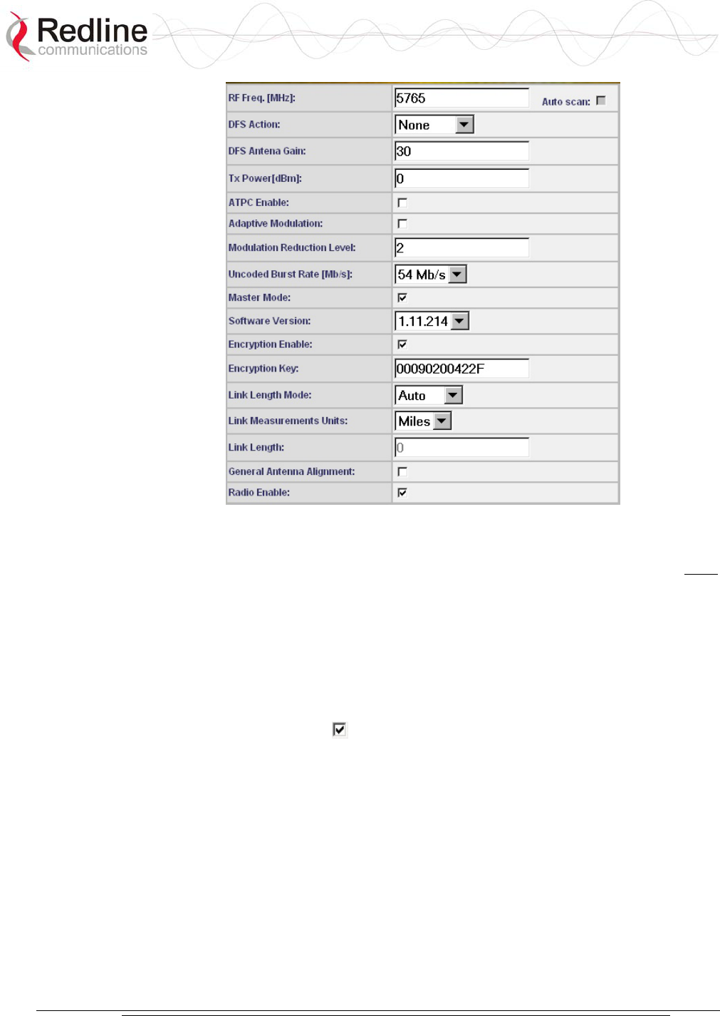
Figure 19: System Configuration Screen - Wireless Settings
RF Freq. [MHz]: The system is shipped with a default RF setting. This setting must
be changed before allowing the radio to transmit. Channel availability is dependent
on the regional regulatory requirements.
Enter the channel center frequency of the system. The table below specifies the center
frequencies of each permitted channel. To avoid interference, the channel frequencies
of two links operating within close proximity must be separated at least twenty MHz.
The availability of frequency bands listed in the following tables is based on the
factory entered option key.
Auto Scan: Check this box to enable subscriber systems to scan the frequency
band for active base stations. The availability of channels is limited by regional
regulations.
It is important that this feature is enabled on the subscriber system when the master-
end system has DFS Action is set to Chg Freq. This setting allows automatic link
recovery following a DFS event.
Additional detailed installation information is available in the manual titled
"Installation Guidelines for Redline AN-30e PTP Systems" also provided on AN-30e
CD-ROM. This guide provides instructions for site planning and installation
including weatherproofing and antenna alignment.
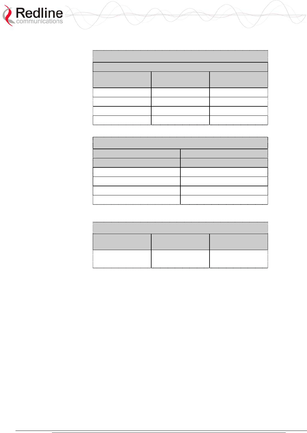
AN-30e
user manual
70-00035-01 Proprietary Redline Communications © 2004 November 2004
Page 43 of 104
The following table lists the 5.4 GHz channels available in CE regulated regions.
Table 15: CE: RF Channel Frequencies
T-54 Radio: 5.4 GHz
Center Frequency
(GHz)
Center Frequency
(GHz)
Center Frequency
(GHz)
5.500 5.580 5.660
5.520 6.500 5.680
5.540 5.620 5.700
5.560 5.640
The following table lists the 5.8 GHz channels available in the United Kingdom.
Table 16: UK: RF Channel Frequencies
T-58 Radio: 5.8 GHz T-58e Radio: 5.8 GHz
Center Frequency (GHz) Center Frequency (GHz)
5.735 5.735
5.755 5.755
5.775 5.775
5.835
The following table lists the 5.8 GHz channels available in North America.
Table 17: North America: RF Channel Frequencies
T-54 Radio:
5.4 GHz
T-58 Radio:
5.8 GHz
T-58e Radio:
5.8 GHz
5.480 to 5.715
(steps of 5 MHz)
5.735 to 5.815
(steps of 5 MHz)
5.735 to 5.840
(steps of 5 MHz)
DFS Action: Select the mode of operation for DFS.
The system set to master-mode monitors for interference from radar devices and other
equipment using the same channel frequency. When interference is detected, the
system automatically takes the action selected using the drop-down menu:
Important: DFS Action selection should be set to None where DFS function is not
required by regulations. DFS cannot be disabled where required by regional
regulations.
None: DFS is disabled.
Tx Off: Transmission is immediately disabled when radar signals are detected.
This action is recorded in the message log and an SNMP trap message is sent (if
SNMP enabled).
Following an interval of thirty minutes, the same channel is monitored for one
minute and if there are no DFS triggering events, the system resumes normal
operation. If DFS trigger conditions are still detected, operation is suspended for
an additional thirty minutes. This cycle continues until no DFS trigger events are
detected or the operator manually reconfigures the system.

AN-30e
user manual
70-00035-01 Proprietary Redline Communications © 2004 November 2004
Page 44 of 104
Chg Freq: Relocate transmission to alternative frequency immediately when
radar signals are detected. This action is recorded in the message log and a trap
message is sent (if SNMP enabled).
The new channel is selected based on allowable frequencies for the regulatory
region of that installation. The channel is monitored for one minute before the
system is allowed to transmit. If DFS triggering events are detected, the next
available channel is selected and monitored. The system is not allowed to
return to a channel on which DFS trigger events were detected for a period of
thirty minutes. If DFS trigger events are detected on all channels the system
suspends operation until the thirty-minute time interval expires for at least one
channel.
DFS Antenna Gain: Enter the gain (dBm) for the system antenna.
It is important that this value is set to correctly match the antenna gain. If the antenna
gain is set higher than the actual antenna gain, the DFS is less sensitive to detecting
interference, and the system is not operating in compliance with the UK/ETSI
standard. If the antenna gain is set lower than the actual antenna gain, the DFS is
more sensitive to detecting interference and may cause false triggers.
Important: The DFS Antenna Gain must be set when DFS is required by regional
regulations.
Tx Power [dBm]: Enter the default Tx power level (dBm).
Section 8.3: Antenna and Power Specifications on page 81 lists the maximum
transmit power setting based on the antenna gain for a series of frequency settings.
There are restrictions on the maximum transmit power settings when operating at data
rates above 24 Mb/s.
Note: In some countries outside of North America, the maximum operational power
per channel for a specific antenna is limited in accordance to maximum allowable
EIRP levels for the region. Refer to the CE notice in the first section of this manual.
ATPC Enable: Check this box to enable the ATPC on the system operating in
master-mode. Both systems automatically adjust the Tx power levels based on
feedback received from the system at the other end of the link.
Important: ATPC cannot be disabled where required by regional regulations.
Adaptive Modulation: Check this box to enable adaptive modulation mode.
When adaptive modulation is enabled, the system measures RF performance (BER)
and automatically adjusts to the highest available modulation/coding combination. If
packet errors exceed one in one million, the system automatically steps down the
modulation/coding to maintain the link at an acceptable BER rate.
It is not recommended to enable adaptive modulation mode when using TDM traffic.
Transient fade conditions may reduce the system throughput to a level incapable of
supporting TDM transport. When dynamic modulation is disabled, the Uncoded Burst
Rate and the Modulation Reduction Level settings must be set manually. Adequate
testing must be performed to ensure that sufficient error-free bandwidth is available
for the number of TDM channels to be deployed.

AN-30e
user manual
70-00035-01 Proprietary Redline Communications © 2004 November 2004
Page 45 of 104
Modulation Reduction Level: This manual setting specifies how many levels the
system must drop in modulation during re-transmission of erroneous wireless packets.
The level can be set from 0-7, with '2' being the recommended value. Valid only
when Adaptive Modulation is disabled.
Uncoded Burst Rate [Mb/s]: Select the desired uncoded burst rate for the link.
Master-mode: Check this box to operate this system as a sector controller.
Each PTP link is comprised of a sector controller and a subscriber system. Check the
Master tick box in the Configure System screen of the web interface to configure a
system to operate as a sector controller. The sector controller establishes and manages
the bi-directional data link with the subscriber system. Uncheck the Master tick box
in the to configure the system to operate as the subscriber station.
Important: Only one system in a wireless link must be set for Master-mode.
Software Version: Select the version of the system software to be loaded when the
system is rebooted.
The system includes flash memory to hold two independent software images. This
allows updates to be uploaded without disrupting operation of the system. See Upload
Software Section 5.6: for additional details.
Encryption Enable: Check this box to enable over-the-air encryption.
Encryption must be enabled or disable on both communicating or the system is
unable to transfer any Ethernet packets. See also Encryption key following.
Encryption Key: The correct encryption key must be entered on both communicating
systems when encryption is enabled.
Enter the MAC address of the communicating AN-30e system as the data encryption
key for each system.
Link Length Mode: Method for specifying the distance between AN-30e systems.
Auto: Distance calculated automatically (recommended).
Manual: Operator enters distance.
Link Measurements Units: Select the units for the Link Length Mode field.
Miles: Link distance is displayed in miles.
Kilometers: Link distance is displayed in kilometers.
Link Length: Enter the actual (maximum) distance between the pair of AN-30e
systems. Valid only when Link Length Mode is set for Manual.
General Antenna Alignment: Check this box to enable the antenna alignment
audible tone generator in the transceiver.
Radio Enable: Check this box to enable the radio transmitter.

AN-30e
user manual
70-00035-01 Proprietary Redline Communications © 2004 November 2004
Page 46 of 104
5.5.3 System Configuration Buttons
Save: Click this button to save the current parameter settings. Note that changing
some parameters initiates a system reboot.
Test: Click this button to have the system activate the current configuration settings
for a period of five minutes. Click Save at any time during this period to permanently
save the current settings. Following this interval the system reboots and loads the
previously saved settings (test settings are discarded).
System Reset: Click this button to reboot the system. Resets all statistics and unsaved
changes to the configuration are discarded.
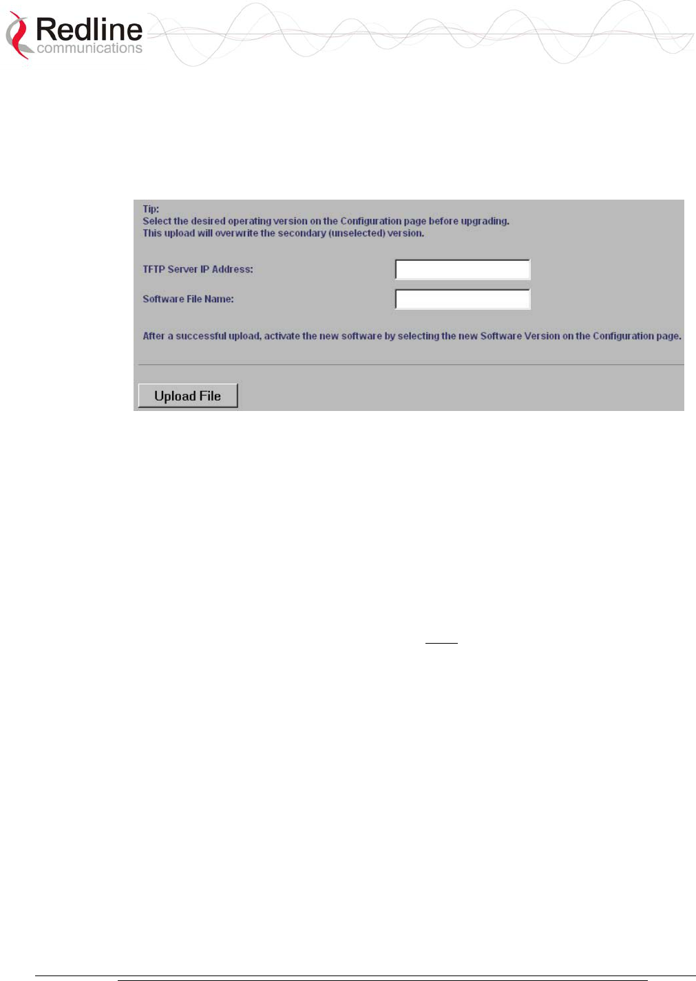
AN-30e
user manual
70-00035-01 Proprietary Redline Communications © 2004 November 2004
Page 47 of 104
5.6 Upload Software
Click Upload Software in the left hand menu to display the Upload AN-30e Software
screen. The upload screen shown is used to upgrade the terminal with new software
stored in a binary file on a server or host computer.
Figure 20: Upload Software Screen
TFTP Server IP Address: IP address of the computer that runs the TFTP server that
contains the upgrade software in binary format.
Software File Name: Name of the binary file including the file extension.
The terminal contains two non-volatile RAM banks for storing two versions of the
software. The upload overwrites the non-operational (unselected) version.
Trivial File Transfer Protocol (TFTP) is used to upload the new software image file
from your computer to the AN-30e system. TFTP server software must be installed
and running on the computer you are using to upload the new software file. In
addition, the AN-30e software binary file must be located in the default upload
directory for the TFTP server.
1. Enter the TFTP Server IP Address and File Name.
2. Click the Upload File button to begin the file transfer. The upgrade file size is
approximately two Megabytes and takes approximately two to four minutes to
download from the server to the terminal memory.
3. When the file transfer is complete, the terminal verifies the integrity of the new
software. If errors were introduced during the transfer process, the new software
file is rejected and a warning is logged indicating the upgrade was unsuccessful.
You must repeat the upload process.
4. Use the System Configuration screen (section 5.5) to select the current operating
version of system software.
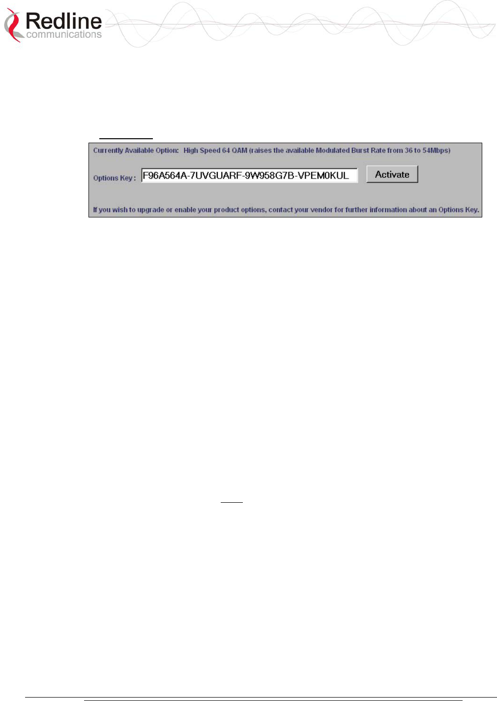
AN-30e
user manual
70-00035-01 Proprietary Redline Communications © 2004 November 2004
Page 48 of 104
5.7 Product Options
Click AN-30e Options in the menu (left side of screen) to enter an Option Key. An
Options Key is a 32-character string, containing four dashes. Entering the options key
is mandatory for system operation.
Figure 21: AN-30e Product Options Screen
The option key is recorded on a sticker affixed to the terminal. A single key combines
all Ethernet and TDM options purchased for the AN-30e terminal. If an upgrade is
purchased after the system is installed, a new key combines all selected options.
Note: Each key is personalized to a specific terminal MAC address. Please ensure
that the correct MAC address is provided when purchasing an upgrade option from
your local representative.
5.7.1 Entering Option Keys
Enter the key (case sensitive) and check to see that it is correct. Click Activate to
enter the key. The key is case sensitive and must include hyphens.
Click System Log in the left-hand menu to view the log. If the key was accepted there
will be a message 109-Product Options Key activated. If the key was not accepted, try
re-entering the key (possible typing error).
5.7.2 TDM Options
The AN-30e unit is equipped from the factory with eight software-configurable TDM
ports. The Options Key activates and configures the active TDM ports.
Important: The option key must be entered before the TDM ports are connected to
any external equipment.
5.7.3 Ethernet Options
High-speed Ethernet options are provided to allow Ethernet data traffic and TDM
data to be transmitted concurrently over the wireless link. Review the following
section for additional information.
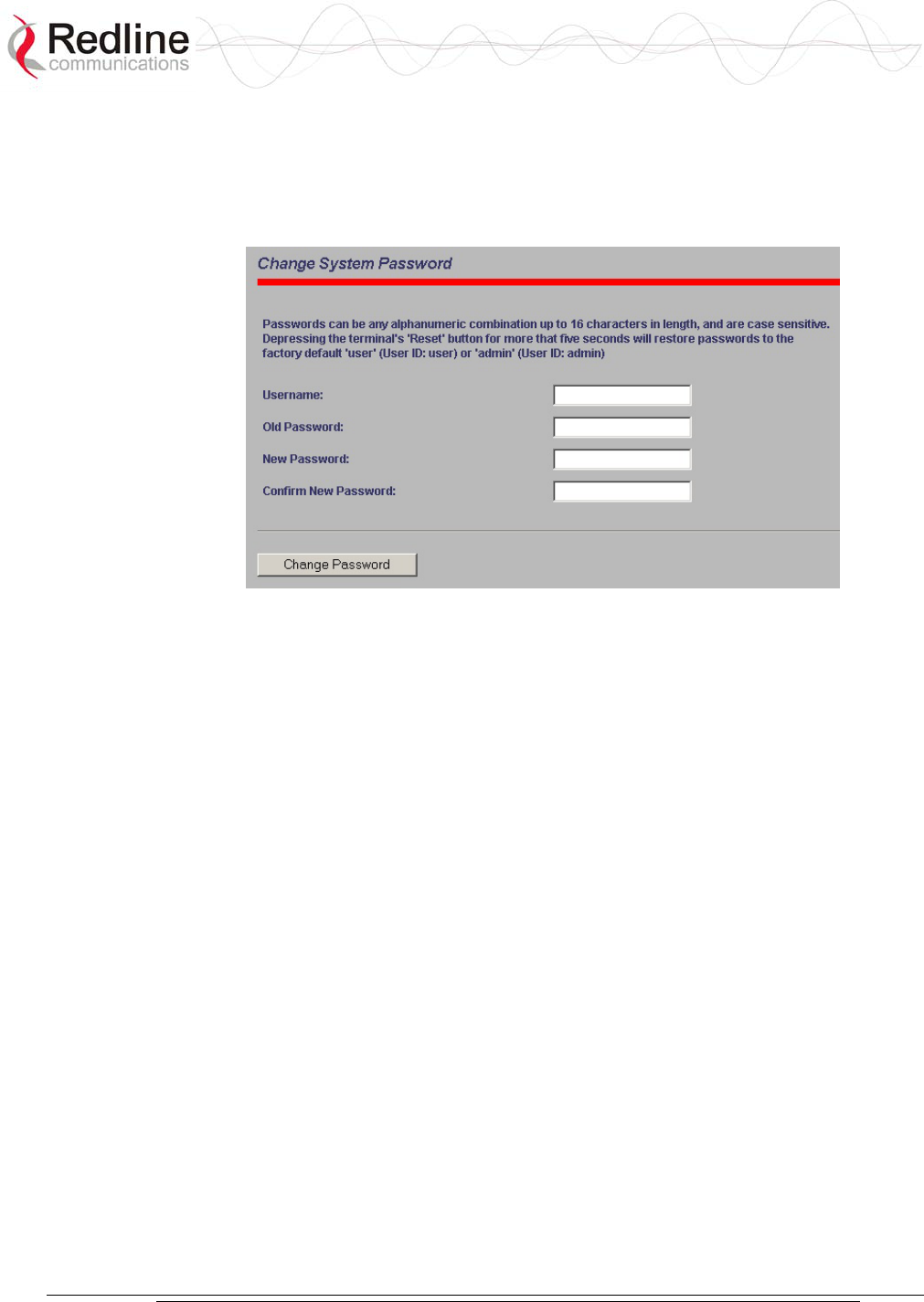
AN-30e
user manual
70-00035-01 Proprietary Redline Communications © 2004 November 2004
Page 49 of 104
5.8 System Password Screen
Clicking on System Password in the left hand menu displays the System Password
screen. This screen allows the operator to modify the system passwords.
Figure 22: System Password Screen
To change the password, enter the username and the old password. Enter a new
password in the two lower fields using any alphanumeric combination. Note the field
is case sensitive and can be up to sixteen characters in length.
Username: Enter user name.
Old Password: Enter current password.
New Password: Enter new password.
Confirm New Password: Re-enter new password (avoids typing errors).
Note: The original factory default passwords can be restored by depressing the front
panel reset button for more that five seconds (long-reset). This also resets some other
parameters to factory default settings.
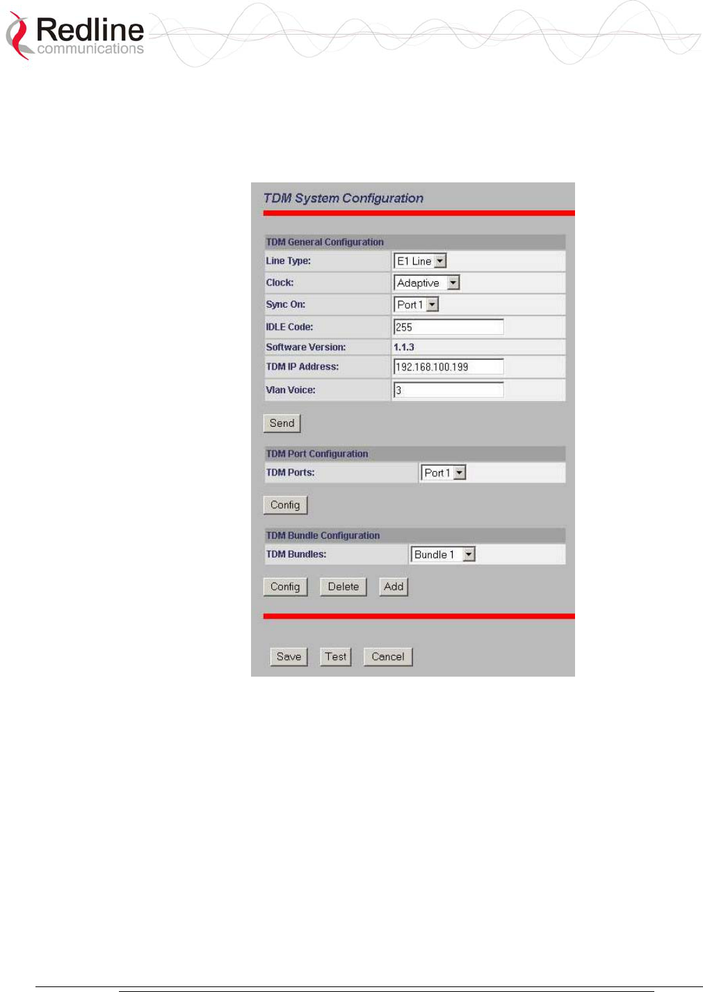
AN-30e
user manual
70-00035-01 Proprietary Redline Communications © 2004 November 2004
Page 50 of 104
5.9 TDM Configuration Settings
Click TDM Config in the menu (left side of screen) to view and modify the TDM
settings. There are four sections in the TDM System Configuration screen:
Figure 23: TDM System Configuration Screen
TDM General Configuration: Global settings for the TDM interface.
TDM Port Configuration: Configure a specific port.
TDM Bundle Configuration: Configure a specific bundle on a port.
TDM Controls: Buttons to save or cancel changes.
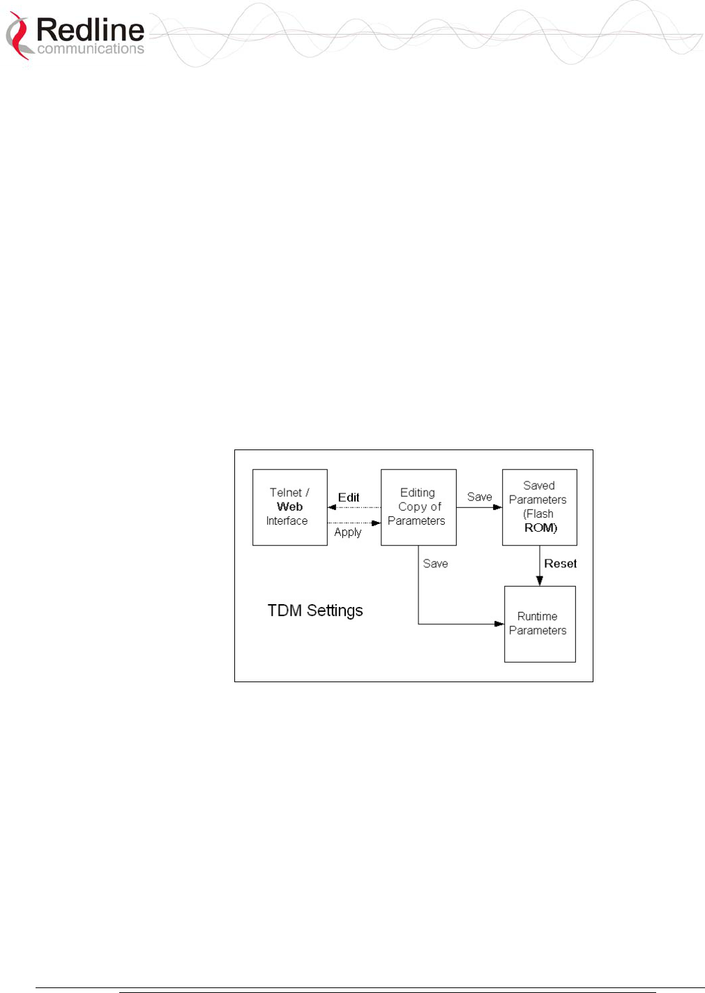
AN-30e
user manual
70-00035-01 Proprietary Redline Communications © 2004 November 2004
Page 51 of 104
5.9.1 How to Use Apply and Save
Configuration of the TDM module is a multi-step process. There are separate
screens for configuring the general parameters, ports, and timeslots (bundles). To
avoid creating instability during changes to the configuration, it is recommended
to complete all editing steps before saving the changes.
The AN-30e provides an editing template where all changes are made to the TDM
configuration in an off-line mode. Changes to this template do not effect the
operation of the TDM module.
When TDM Config is selected in the main menu (left of screen) the AN-30e
creates an offline-editing template using a copy of the current TDM settings.
When any change is made to the general, port, or bundle settings, you must click
Apply to save these changes to the offline-editing template. If you exit a TDM
screen without clicking Apply, any changes made in that screen are discarded.
When you click Save at the bottom of the TDM General Configuration screen, all
settings in the offline-editing template are copied into permanent memory and
loaded as the running parameters for the TDM module.
Figure 24: TDM Editing Steps
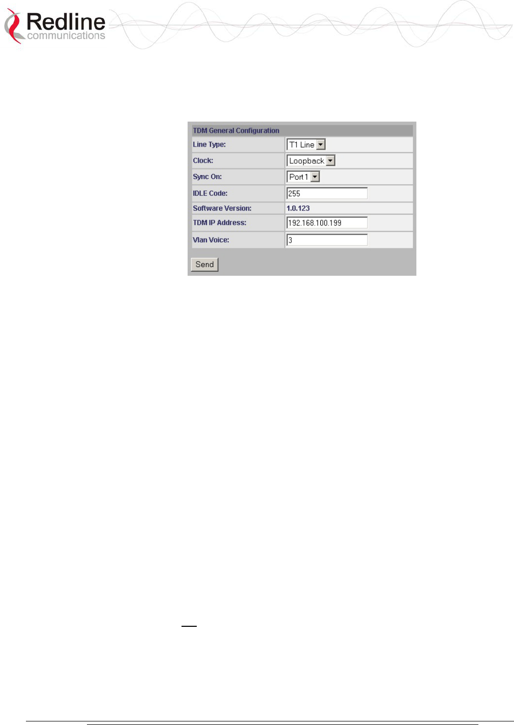
AN-30e
user manual
70-00035-01 Proprietary Redline Communications © 2004 November 2004
Page 52 of 104
5.9.2 TDM Config - General Settings
The TDM General Configuration fields are in the main TDM System Configuration
screen. The TDM General Settings apply to all TDM ports.
Figure 25: TDM General Configuration Settings
Line Type: Select the type of the serial port interface.
E1 Line: TDM port interface is E1.
T1 Line: TDM port interface is T1.
Clock: Set the TDM clocking mode for the TDM module. All TDM ports use the
same clock for transmitting and receiving.
In a typical link deployment, the AN-30e located closest to a master clock is set for
Rx Loop, while the remote-end is set to adaptive clocking.
Rx Loop: Select Rx Loop mode at the network (master clock) end of the wireless
link. Only one AN-30e system should be set to Rx Loop mode.
In Rx Loop mode the AN-30e reference clock is derived from the receive signal
of an active TDM port (see Sync On field). All TDM ports use this clock for
transmission and reception.
If there is no signal on the specified TDM port, then all ports default to using the
internal AN-30e reference clock.
Adaptive: Select adaptive mode at the remote-end (CPE end) of the link.
In adaptive mode the AN-30e clock begins with a default clock speed and then
continuously modifies the clock signal (adapting +/-) based on the jitter buffer
level for the E1 port specified in the Sync On field.
Internal: The AN-30e internal clock is used as the TDM clock.
This setting is not recommended for in-service applications.
Sync On: Select the TDM port to use for clock synchronization. The effect of this
setting is dependent on the clock setting (above):
If Rx Loop Mode is selected the AN-30e clock is derived from the receive signal on
an active TDM port. At least one active bundle must be assigned to the selected port.

AN-30e
user manual
70-00035-01 Proprietary Redline Communications © 2004 November 2004
Page 53 of 104
If Adaptive Mode is selected the AN-30e clock is derived from the jitter buffer level
of an active TDM port. A single active bundle must be assigned to the selected port.
The designated TDM port must have only one active bundle assigned when the clock
is set to adaptive mode.
Idle Code: Enter the idle code value. This code can be changed to match the
deployment network. The default is 255 decimal. An incorrect idle code may cause
synchronization errors.
The idle code is inserted into all unused time slots when the TDM signal is
regenerated at the remote-end (fractional or buffer underrun).
Software Version: This field displays the software version currently running on the
TDM interface.
TDM IP Address: Use this field to set the IP address of the TDM module.
This IP address uniquely identifies the AN-30e TDM module.
TDM
Ports
Ethernet
Port
Wireless
Interface
AN-30e
TDM
Port IP
Ethernet
Port IP
Figure 26: TDM IP Address Settings
The subnet mask is set as the default for the class of IP address entered. The mask
value cannot be changed.
Vlan Voice: Enter the tag number to use for TDM traffic. Enter any value from 0 to
2095.
If a non-zero number is entered, the TDM traffic will be transported as high priority
using the entered VLAN tag, and will not appear on the Ethernet port.
If a value from 1 to 2095 is entered, the TDM traffic will be transported as regular
Ethernet traffic, will appear on the Ethernet data port, and will have the same priority
as other data traffic including in-band management. This setting is necessary in a
multi-hop scenerio where the TDM traffic must be routed between local AN30e/AN-
50e systems using the Ethernet data port.
Send: Click Send to save the general settings. If you do not click Send, the changes
will be discarded when you exit this screen.
Note: Clicking Send does not permanently save the current settings or make these
settings active. You must click Send and then click Save in the TDM General
Configuration screen to permanently save any new settings for the TDM board.
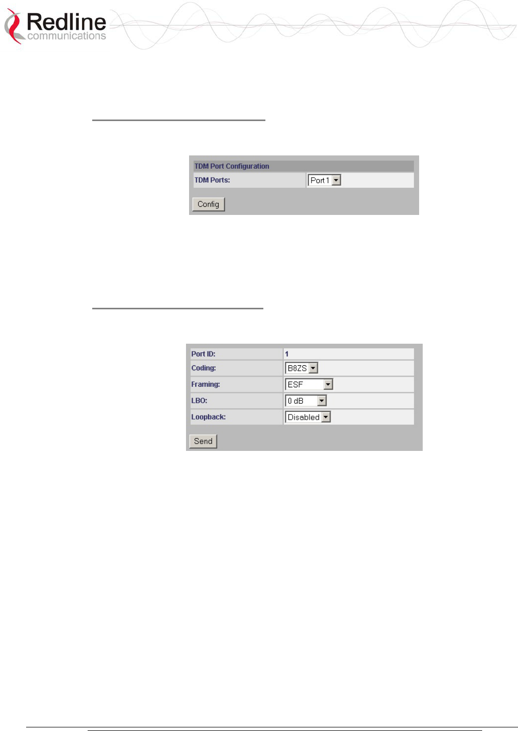
AN-30e
user manual
70-00035-01 Proprietary Redline Communications © 2004 November 2004
Page 54 of 104
5.9.3 TDM Config - Port Settings
Use the TDM Port Configuration fields to select and edit port settings.
Step 1. Select a TDM Port
Use the drop-down menu to in the TDM Port Configuration field to select a TDM
port. Click the Config button to view the editing screen.
Figure 27: TDM Port Configuration Settings
TDM Ports: Select the TDM interface port to configure.
Config: Click the Config button to view the Configure Port dialog screen.
Step 2. Edit Port Settings
Set the line characteristics for the selected TDM port. Selections will depend on the
selected line type.
Figure 28: TDM Port Editing Screen
Port ID: Displays the selected interface port (from 1 to 8).
Coding: Select the line coding type for this interface. Available options depend on
the interface line type.
The selections for T1 are:
AMI: Select this setting for Alternate Mark Inversion coding.
B8ZS: Encoding where a special code is substituted whenever eight consecutive
zeros are sent over the link.
The selections for E1 are:
AMI: Select this setting for Alternate Mark Inversion coding.
HDB3: Select this setting for High-Density Bipolar 3 coding.
Framing: Select the type of framing the selected port. Available selections are
dependent on the interface line type.
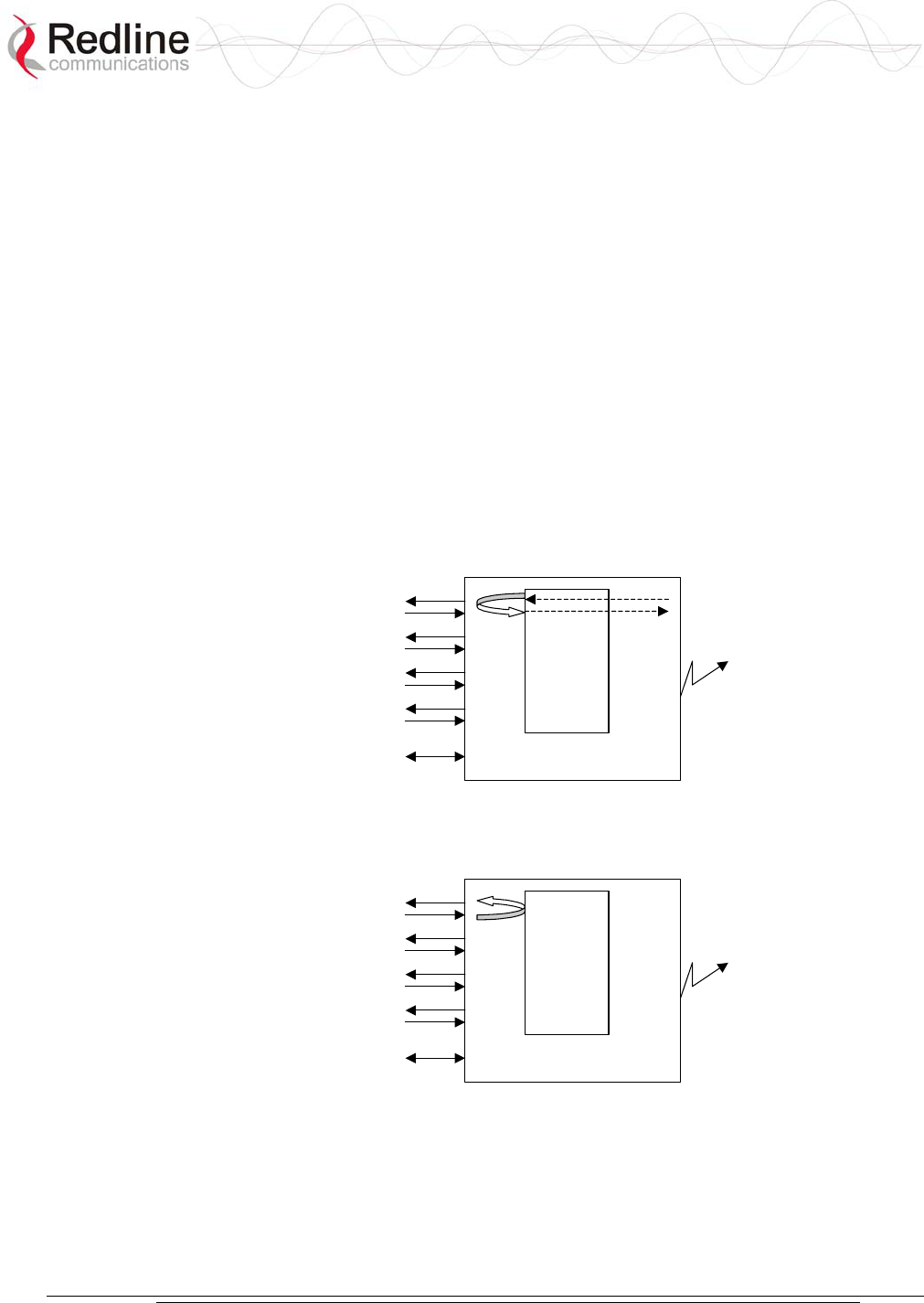
AN-30e
user manual
70-00035-01 Proprietary Redline Communications © 2004 November 2004
Page 55 of 104
The selections for T1 are:
D4: The D4/Superframe format groups twelve T1 frames together and utilizes the
twelve T1 framing bits to provide a repetitive pattern that allows other equipment
on T1 line to lock onto the framing pattern.
ESF: Extended SuperFrame framing format groups twenty-four T1 frames
together. Allows optimization for framing on the T1 line. Adds additional features
of CRC, FDL, and frame synchronization (like D4).
unframed: The entire T1 signal is forwarded without modification.
The selections for E1 are:
FAS: Framing scheme where timeslot zero of every even frame is reserved for the
Frame Alignment Signal (FAS) code.
CRC4: Cyclic Redundancy Check.
unframed: The entire E1 signal is forwarded without modification.
Loopback: Select the testing mode for this port.
Disabled: Serial interface is in normal operating mode
Local: Equivalent to a physical RJ-48 loopback.
Framer
Line 1
Line 2
Line 3
Line 4
ETH AN30
Wireless
Figure 29: TDM Loopback: Local Mode
Remote: Physical loopback at the analog part of a E1 line.
Framer
Line 1
Line 2
Line 3
Line 4
ETH AN30
Wireless
Figure 30: TDM Loopback: Subscriber Mode
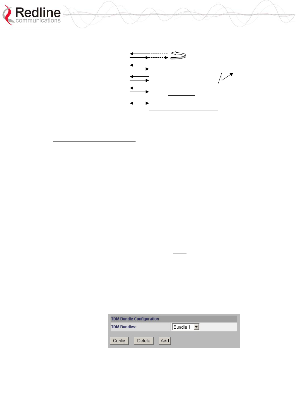
AN-30e
user manual
70-00035-01 Proprietary Redline Communications © 2004 November 2004
Page 56 of 104
Payload: The framer rebuilds the coding/framing information.
Framer
Line 1
Line 2
Line 3
Line 4
ETH AN30
Wireless
Figure 31: TDM Loopback: Payload Mode
Step 3. Save Settings
Send: Click Send to save the general settings. If you do not click Send, the changes
will be discarded when you exit this screen.
Note: Clicking Send does not permanently save the current settings or make these
settings active. You must click Send and then click Save in the TDM General
Configuration screen to permanently save any new settings for the TDM board.
5.9.4 TDM Config - Bundle Selection
The TDM Bundle Configuration settings allow you to send full or fractional channels
over the wireless. Use of fractional channels can preserve bandwidth by sending data
for only the designated sets of timeslots.
The TDM Bundle Configuration settings allow you to specify up to eight full or
fractional E1 bundles. Use of fractional services can save bandwidth by sending only
the designated sets of timeslots. Framing must be selected on ports where fractional
bundles are specified.
TDM signals are transported by encapsulating timeslot data within Ethernet packets.
The AN-30e supports multiple packet streams, each grouping one or more timeslots.
Each bundle may be assigned a separate destination address. If Fractional E1 is used,
multiple bundles can be defined to a single port. This feature allows multiple
fractional channels from remote-end AN-30e systems to be combined onto a single
port of a network-connected AN-30e system.
Figure 32: TDM Bundle Selection
TDM Bundles: Use this drop-down menu to select a bundle.
Config: Edit the selected bundle definition.
Delete: Delete the selected bundle definition.
Add: Create a new bundle definition.

AN-30e
user manual
70-00035-01 Proprietary Redline Communications © 2004 November 2004
Page 57 of 104
TDM signals are transported by sampling the TDM port signals, and encapsulating
the timeslot data in Ethernet packets. The AN-30e supports up to eight separate
packet streams, each grouping from one to thirty-two consecutive timeslots. Each
bundle may be assigned to a separate destination IP address.
If Fractional E1 is used, multiple bundles can be defined for a single port. This
feature allows multiple fractional channels from one AN-30e system to be combined
on a single port of a network-connected AN-30e system.
Restrictions:
- Maximum of eight bundles for the terminal.
- Bundle definitions cannot span serial ports.
- Fractional bundle definitions on the same serial port must not overlap.
- You must specify the framing format for fractional bundles. The framing
information is required to extract the timeslot data.
- Multiple fractional bundle definitions on the same serial port must not have the
same destination port. Each bundle must specify a unique port at each termination
point.
- Signaling is not monitored by the AN-30e system. If signaling is required for
fractional E1, the signaling timeslot must be included in the bundle.
Viewing and modifying the TDM bundle settings is a three-step operation:
1. Select a TDM bundle to view or change and click Config.
2. View and modify the bundle settings in the Configure Port screen.
3. Click Send in the Configure Bundle screen.
To make these changes permanent you must also click Save in the TDM General
Configuration screen.
Step 1. Select a Bundle
Use the drop-down menu to select a TDM bundle. Click Add to create a new
definition or click Config to change an exiting bundle definition.
Step 2. Edit Port Settings
These settings apply only to the bundle selected by the Bundle ID drop-down
selection in the TDM System Configuration screen.
Figure 33: TDM Bundle Editing Screen
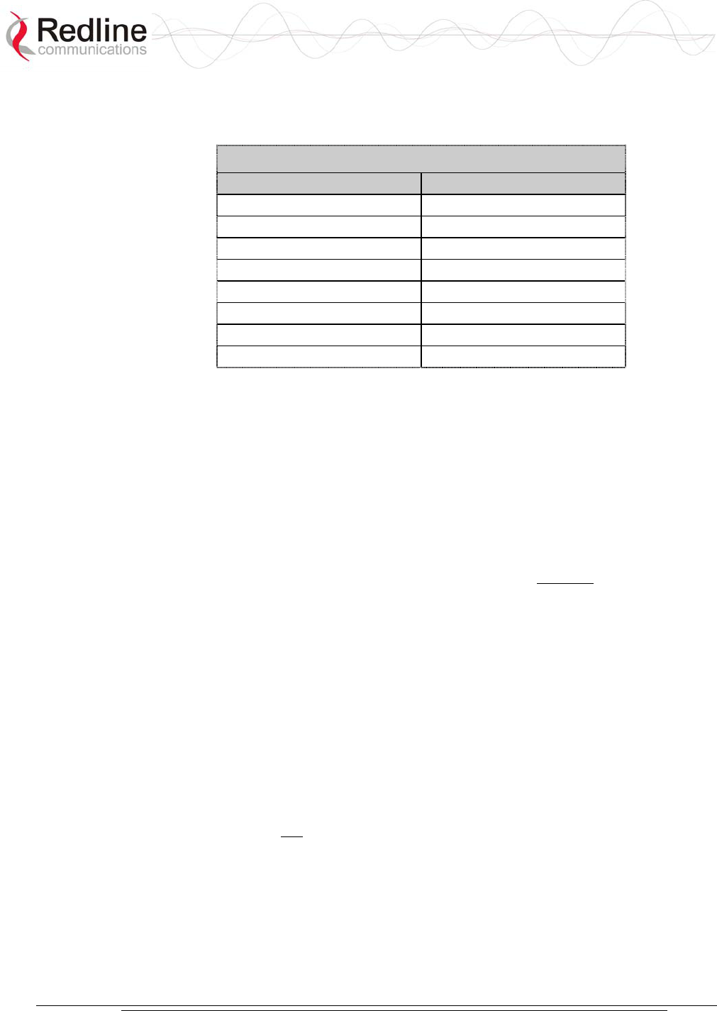
AN-30e
user manual
70-00035-01 Proprietary Redline Communications © 2004 November 2004
Page 58 of 104
Bundle ID: This is the bundle identifier for the TDM port. Each port has a default
bundle ID (see following table). There are 32 time-slots reserved for each port. The
following table lists the time slot numbers assigned to each port.
Table 18: Default Bundle Numbers
Port Bundle ID
1 1-32
2 33-64
3 65-96
4 97-128
5 129-160
6 161-192
7 193-224
8 225-256
The Bundle ID has a default name of the first time-slot for the port. If fractional
channels are used, the first bundle must use the default name and any additional
bundles defined for the same port should use the number of the first time-slot of that
bundle. For example, fractionalizing port 1 into two channels could result in
definitions of the first bundle ID = 1, and the second bundle ID = 16.
Note: The same Bundle ID must be used at the destination AN-30e system.
Dest Bundle: This is the bundle ID for the subscriber. The default value is the same
as the Bundle ID.
Begin TS: Enter the first active timeslot of this bundle.
Framed: Begin TS selection is from 1 to 32. Framing is required when specifying
fractional bundles.
Unframed: Begin TS must be '0'. Time-slot 0 is required to transport timing and
signaling information.
Number TS: The number of contiguous time-slots in this bundle (starting at Begin
TS). There are thirty-two time-slots reserved for each port.
Framed: Number TS may be from 1 to 31.
Unframed: Number TS must be set to 32.
Dest IP: Enter the IP address of the destination TDM module.
The Dest IP setting allows bundles to be sent to a specific TDM module on an AN-
30e system. This IP address is the TDM IP Address set in the TDM General
Configuration screen (not the IP address in the System Configuration screen).
Jitter Length: Specify the delay variation compensation for all ports on the OTM
module (8 - 300 ms).
The jitter buffer is used to compensate for delays in processing and transporting
encapsulated TDM traffic between AN-30e systems. Using the Ethernet port for in-
band management or user-data transport requires higher jitter buffer settings
(proportional to the Ethernet throughput). The Jitter Length should be set to the
lowest value possible that does not trigger errors on the TDM interfaces.

AN-30e
user manual
70-00035-01 Proprietary Redline Communications © 2004 November 2004
Page 59 of 104
Packet Length: Set the Ethernet packet length used by this bundle (from 128 to 1024
bytes).
The Packet Length setting determines the amount of TDM timeslot data collected
before the Ethernet packet is sent to the remote AN-30e system. Each timeslot sample
requires eight bytes of data.
Step 3. Save Settings
Send: Click Send to save the general settings. If you do not click Send, the changes
will be discarded when you exit this screen.
Note: Clicking Send does not permanently save the current settings or make these
settings active. You must click Send and then click Save in the TDM General
Configuration screen to permanently save any new settings for the TDM board.
5.9.5 TDM System Configuration Control Buttons
Use these control buttons at the bottom of the TDM General Configuration screen to
test, save, or cancel changes to the TDM interface.
Figure 34: TDM Bundle Editing Dialog Box
Save: Click Save to save the current parameter settings.
Test: Click this button to have the system activate the current configuration settings
for a period of five minutes. Click Save at any time during this period to permanently
save the current settings. Following this interval the system reboots and loads the
previously saved settings (test settings are discarded).
Cancel: Click the cancel to discard all changes since the last save command.
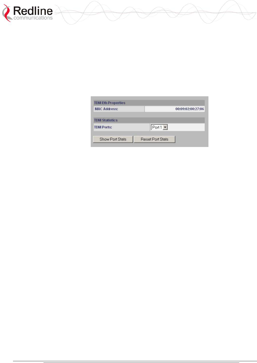
AN-30e
user manual
70-00035-01 Proprietary Redline Communications © 2004 November 2004
Page 60 of 104
5.10 TDM Statistics
Click TDM Stats in the menu (left side of screen) to view the TDM Statistics
selection dialog screen.
5.10.1 TDM Statistics - Port Selection
In the TDM System Configuration screen, use the TDM Statistics drop-down menu to
select a TDM port. Click the Config button to view the statistics screen.
Figure 35: TDM Properties/Statistics Screen
MAC Address: Displays the MAC address of the TDM interface.
TDM Ports: Use the drop-down menu to select a port on the TDM interface.
Show port Stats: Click Show Port Stats to view the Ethernet statistics for the TDM
port selected in the TDM Ports field.
Reset Port Stats: Click Reset Port Stats to zero all statistics counters for the TDM
port selected in the TDM Ports field.
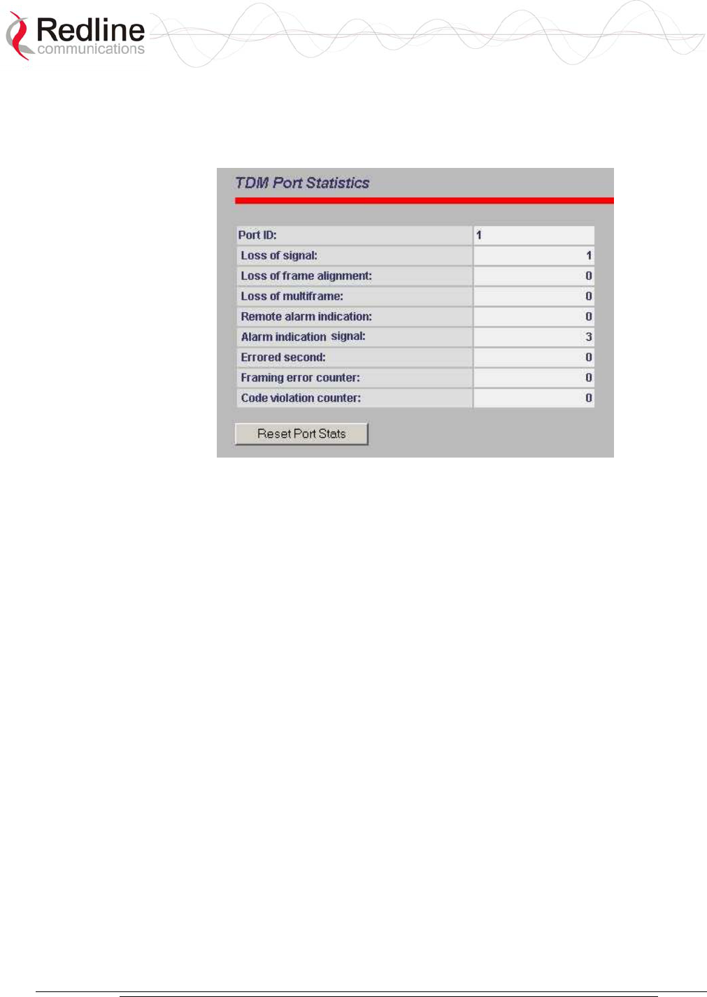
AN-30e
user manual
70-00035-01 Proprietary Redline Communications © 2004 November 2004
Page 61 of 104
5.10.2 TDM Statistics - Statistics Screen
The TDM Port Statistics screen displays line statistics for the port selected in the
TDM System Configuration screen.
Figure 36: TDM Port Statistics Screen
Port ID: TDM interface port being monitored.
Loss of Signal: No pulses are detected at the input port for a period of 175 bits.
Loss of Frame Alignment: At least three consecutive FAS frames are received in
error (E1).
Loss of multiframe: Two consecutive multiframe alignment signals have been
received with an error.
Remote Alarm Indication: A red carrier-failure alarm exists at the remote network
interface location.
Alarm Indication Signal: AIS alarm is a notification sent to upstream devices to
inform them that the originating signal has been lost.
Errored second: An Errored Second has one or more of the following errors: Path
Code Violation (PCV), Out of Frame defects (OOF), or Alarm Indication Signal
(AIS).
Framing error counter: Number of frames with errors.
Code violation counter: A bipolar violation or a pulse-density violation.
Reset Port Stats: Click to zero all statistics counters for this port.

AN-30e
user manual
70-00035-01 Proprietary Redline Communications © 2004 November 2004
Page 62 of 104
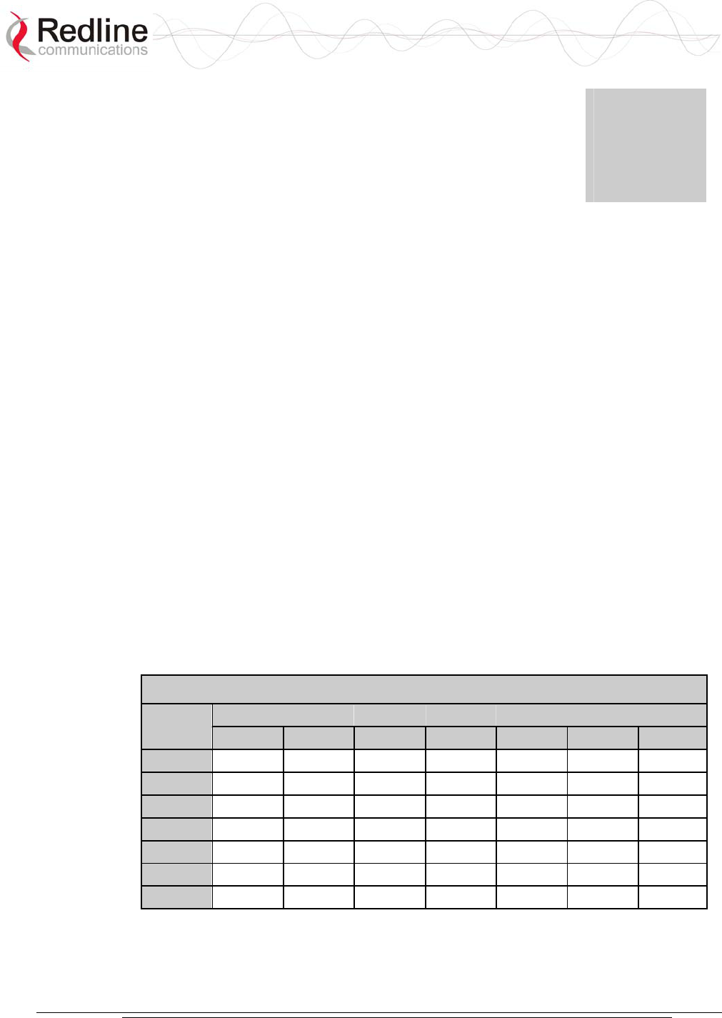
AN-30e
user manual
70-00035-01 Proprietary Redline Communications © 2004 November 2004
Page 63 of 104
Chapter
6
6
6
T
TD
DM
M
O
Ov
ve
er
r
W
Wi
ir
re
el
le
es
ss
s
The AN-30e is designed to simultaneously transport TDM signals and Ethernet data
traffic over a single converged link. The two common AN-30e deployments are for
Mobility Backhaul (TDM-only) and Enterprise backhaul (TDM + data). The
following sections describe the basic operating parameters for each of these two
applications.
6.1 Bandwidth Requirements
An adequate fade margin is needed to maintain the modulated burst rate required to
successfully transport TDM traffic. The working system should be evaluated on the
worst-case modulated burst rate. This consideration must include the possibility of
asymmetrical modulated burst rates for the uplink and downlink, caused by
interference affecting only one direction on the wireless link.
6.1.1 Maximum Uncoded Burst Rates
It is important that adequate testing be performed to demonstrate that sufficient error-
free bandwidth is available for the number of TDM channels to be deployed (see
tables in this section).
The following table lists the maximum uncoded burst rates based on SINADR values.
Table 19: Achievable Uncoded Burst Rate (Mbps)
SINADR RSSI (dBm)
(dB) -65 -70 -77 -81 -83 -84 -86
25 54 - - - - - -
23 48 48 - - - - -
18 36 36 36 - - - -
15 24 24 24 24 - - -
12 18 18 18 18 18 - -
11 12 12 12 12 12 12 -
8 6 6 6 6 6 6 6
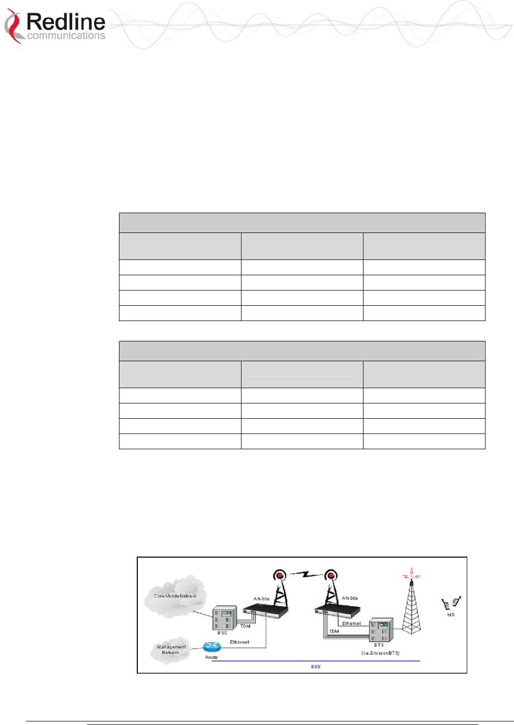
AN-30e
user manual
70-00035-01 Proprietary Redline Communications © 2004 November 2004
Page 64 of 104
6.1.2 Evaluating TDM Throughput Requirements
The modulation and coding settings are regulated by the options key and are specific
for the number of enabled TDM ports (1, 2, 4 or 8). Each TDM port being operated
requires a minimum amount of over-the-air bandwidth. If the actual deployed link
budget is marginal, or you are also sending data traffic on the same link, you may
have to purchase additional bandwidth (higher modulation/coding).
The following tables list the required bandwidth for operating E1 and T1 over the
wireless link. The values provided indicate the (error-free) bandwidth that must be
available exclusively for the TDM traffic.
Table 20: Wireless Link Bandwidth Requirements for T1
Number of Active
T1 Ports
Modulation/Coding Uncoded Burst Rate
(Mbps)
1 BPSK 3/4 9
2 QPSK 1/2 12
4 16QAM 1/2 24
8 64 QAM 2/3 48
Table 21: Wireless Link Bandwidth Requirements for E1
Number of Active
E1 Ports
Modulation/Coding Uncoded Burst Rate
(Mbps)
1 BPSK 1/2 6
2 BPSK 3/4 9
4 QPSK 3/4 18
8 64 QAM 2/3 48
6.1.3 Mobility Networks
The AN-30e can be deployed in most mobility networks. Some networks can have
characteristics that are exceptional and should be reviewed based on actual customer
network configurations. The following figure illustrates a typical mobility backhaul
deployment using the AN-30 wireless system.
Figure 37: AN-30e Mobility Backhaul Deployment
AN-30e
user manual
70-00035-01 Proprietary Redline Communications © 2004 November 2004
Page 65 of 104
Synchronization
The accuracy requirement for this reference signal varies and depends on the mobility
technology. When the reference signal is derived from the TDM network, the
interface originating this signal must be a Stratum 3 clock (see Annex B). If the
requirement is for a Stratum 1 clock, the reference signal is obtained from an external
GPS system.
Latency
The standard for all mobility networks requires an RTD of less than 25 milliseconds
(BSC-to-BTS value including all devices on the link). In some cases, specific vendor
equipment may require an RTD of less than 25 milliseconds.
It is not recommended to send data traffic for mobility network deployment.
Transmitting Ethernet data will increase overall latency on the link. Also, do not use
adaptive modulation, as the modulation/coding shifts introduce latency fluctuations
that may introduce TDM synchronization errors.
Table 22: Mobility Backhaul Operating Characteristics
Performance GSM1 CDMA2
Required Reference
Signal Stability
Stratum 3 Stratum 1
& Stratum 3
Stratum 1
Customer Equipment
Reference Signal Source
GPS3 TDM trunks
and/or GPS
GPS
Round-Trip-Delay (ms) < 16 25 25
1. GSM, GPRS, UMTS
2. CDMAOne, CDMA2000 -1X, CDMA2000 1x EVDO
3. GPS source recommended for clock stability exceeding Stratum 3.
Table 23: AN-30e Operating Settings -- Mobility Backhaul
Ethernet Port 10BaseT, Full Duplex1
Jitter Length (ms) 8
Packet Length (bytes) E1 Unframed (framed): 248 (192)
T1 Unframed (framed): 256 (200)
1. Management traffic only (i.e., HTTP Web interface).
6.1.4 Enterprise Networks
Traditional TDM is used as a last mile transport for data, voice, and video traffic to
Enterprises and private networks. The following figure illustrates a typical Frame
Relay deployment using the AN-30 wireless system.
Synchronization
TDM devices operate in a master-slave relationship and use a reference clock derived
from the TDM signal. The clock accuracy requirement on a TDM network is
dependent on the distance from the equipment to the core. A typical requirement for
enterprises and private networks is Stratum 4 clock.
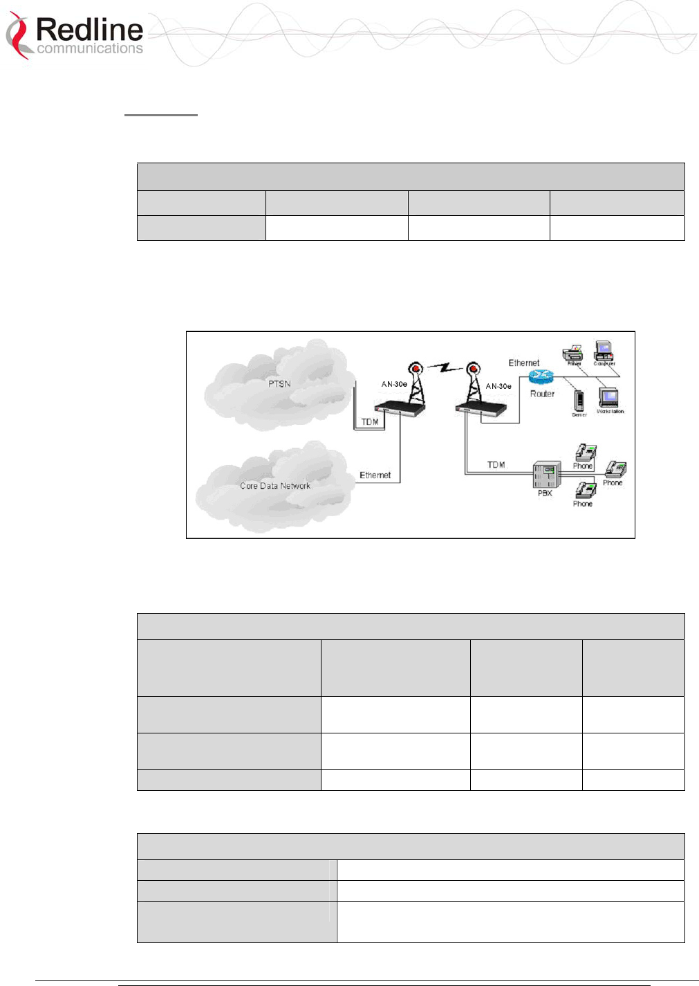
AN-30e
user manual
70-00035-01 Proprietary Redline Communications © 2004 November 2004
Page 66 of 104
Latency
Latency requirements vary and depend on the type of application. The following table
lists the latency requirements for different TDM deployments.
Table 24: Enterprise Backhaul Latency Requirements
Application PBX VoIP Data
Latency1 <150 ms <150 ms Not sensitive
1: End-to-end latency values including all devices on the network.
The following figure illustrates a typical enterprise deployment using the AN-30
wireless system.
Figure 38: AN-30e Enterprise Deployment
The following table lists the operating requirements for enterprise deployments.
Table 25: Enterprise Backhaul Operating Parameters
AN-30e System
Performance
Enterprise
Network
Frame Relay
Network
Required Reference Signal
Stability
Stratum 4 Stratum 4 Stratum 4
Customer Equipment
Reference Signal Source
GPS1 TDM TDM
Return-Trip-Delay (ms) < 60 300 Not Sensitive
1. GPS source recommended for clock stability exceeding Stratum 3.
The following table lists the AN-30e operating settings for enterprise deployments.
Table 26: AN-30e Operating Settings -- Enterprise Backhaul
Ethernet Port 100BaseT, Full Duplex
Jitter Length (ms) 30
Packet Length (bytes) E1 Unframed (framed): 768 (744)
T1 Unframed (framed): 600 (576)
AN-30e
user manual
70-00035-01 Proprietary Redline Communications © 2004 November 2004
Page 67 of 104
6.1.5 Evaluating Ethernet Throughput
The Ethernet data throughput is dependent on protocol, packet size and transmission
latency. The following tables list the Ethernet data throughput available based on the
number of active TDM ports and the port speed (option key) installed on the AN-30e
system.
Table 27: Data Rates Available when Using E1
Number of
Active E1
Ports
Data Option Duplex
Ethernet
Throughput
(Mbps)
Modulation
Mode
Uncoded Burst
Rate (Mbps)
1 17 16 QAM 1/2 24
1 2 27 16 QAM 3/4 36
3 43 64 QAM 3/4 54
1 13 16 QAM 1/2 24
2 2 24 16 QAM 3/4 36
3 38 64 QAM 3/4 54
1 16 16 QAM 3/4 36
4 2 N/A N/A N/A
3 32 64 QAM 3/4 54
1 10 64 QAM 3/4 54
8 2 N/A N/A N/A
3 N/A N/A N/A
Table 28: Data Rates Available when Using E1
Number of
Active T1
Ports
Data Option
Duplex Ethernet
Throughput (Mbps)
Modulation Mode
Uncoded Burst
Rate (Mbps)
1 18 16 QAM 1/2 24
1 2 28 16 QAM 3/4 36
3 44 64 QAM 3/4 54
1 14 16 QAM 1/2 24
2 2 25 16 QAM 3/4 36
3 40 64 QAM 3/4 54
1 18 16 QAM 3/4 36
4 2 N/A N/A N/A
3 34 64 QAM 3/4 54
1 18 64 QAM 3/4 54
8 2 N/A N/A N/A
3 N/A N/A N/A
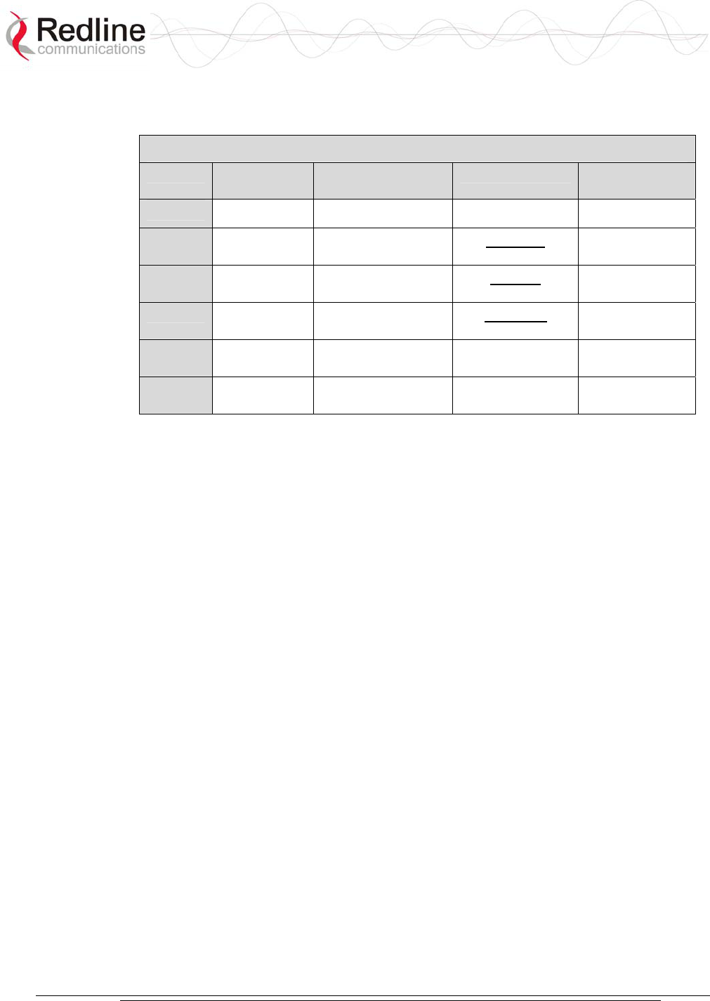
AN-30e
user manual
70-00035-01 Proprietary Redline Communications © 2004 November 2004
Page 68 of 104
6.1.6 Clock Synchronization
The following table lists the Stratum clock requirements and definitions.
Table 29: Stratum Clock Definitions
Stratum Accuracy &
Adjustment
Synchronization
Accuracy
Pull-In-Range Time To First
Frame Slip
1 1 x 10-11 N/A N/A 72 Days
2 1.6 x 10⁻⁸ +/- 1.6 x 10⁻⁸ 1 x 10⁻¹⁰
day
7 Days
3E 1.0 x 10⁻⁶ +/- 4.6 x 10⁻⁶ 1 x 10⁻⁸
day
3.5 Hours
3 4.6 x 10⁻⁶ +/- 4.6 x 10⁻⁶ 3.7 x 10⁻⁷
day
6 Minutes
4E 32 x 10-6 +/- 32 x 10-6 Same as
Accuracy
N/A
4 32 x 10-6 +/- 32 x 10-6 Same as
Accuracy
N/A
AN-30e
user manual
70-00035-01 Proprietary Redline Communications © 2004 November 2004
Page 69 of 104
Chapter
7
7
7
D
Di
ia
ag
gn
no
os
st
ti
ic
cs
s
a
an
nd
d
T
Tr
ro
ou
ub
bl
le
es
sh
ho
oo
ot
ti
in
ng
g
Troubleshooting can be performed using the front panel LEDs and the host
computer/server connected locally or remotely to the terminal.
Before troubleshooting using the front panel LEDs, check that all cables are securely
attached. Also, verify that all fields on the System Configuration page are correct for
both communicating systems. Entry errors in these fields may cause the terminal to be
unable to establish a communication link.
This section provides basic diagnostic and troubleshooting procedures to help solve
problems that may occur with the system. If, after reading this section, you are unable
to get the system operating properly, please contact your local Redline representative.
Include the model name and serial number of the system (located on the back of the
terminal) in your communications.
7.1 Factory Default Settings
The following parameters are the factory default setting for the terminal. These
settings are restored when a long-reset is activated.
Table 30: Factory Default Settings
Section Item Factory Default Setting
System User Name admin
Password admin
Ethernet IP Address 192.168.25.2
Subnet Mask 255.255.255.0
Gateway 0.0.0.0
Wireless RF Channel 5.765 GHz
Tx power 14 dBm

AN-30e
user manual
70-00035-01 Proprietary Redline Communications © 2004 November 2004
Page 70 of 104
7.2 Troubleshooting the Web Interface
These troubleshooting hints assume that the status LEDs on the front panel of the
terminal displays normal functionality.
Table 31: Web Interface Diagnostics
Symptom Possible
Problem
Solution
Incorrect IP
address and/or
Subnet Mask.
Perform a ping test from the host computer
command line.
If the ping test is unsuccessful, then the problem
is with the IP address. Perform a long reset to
apply the default address (192.168.25.2) and
Subnet Mask (255.255.255.0)
Problems with
host computer, or
terminal.
If the ping is successful try a short reset of the
terminal, and/or reboot the host computer.
Home Screen
(General
Information)
cannot be
accessed.
Host PC ARP
table is
incorrectly
configured
Run the command 'arp: -d' whenever the terminal
is swapped. Check that the subnet mask for the
host PC matches the subnet mask of the
terminal. Check that the host PCs address is
192.168.25.n, where n is not equal to 0,2, or 255.
Attempt to login to the terminal using a Web browser. Microsoft Internet Explorer is
recommended. If the terminal does not respond by displaying the login dialog box,
check that the correct IP address is being used. The value 192.168.25.2 is the factory
default value and may have been changed during installation.
The next test is to verify the IP address is reachable from the computer. Use the ping
command to test the connection between the terminal and host computer. The system
always responds to ping frames less that 577 bytes in length.
>Ping 192.168.25.2
If the ping test is successful, the host computer was able to send and receive packets
to/from the terminal. The problem may be with the Internet browser or related
settings on the host computer. Re-boot the host computer to try to resolve the
problem.
If the ping is unsuccessful, there may be problems using that IP address; the IP
address may be incorrect, or there may be a duplicate address. For correct operation
the host computer and the terminal must appear to be on the same subnet. For
example, if the terminal is using the factory default settings, the host computer could
be set for an IP of 192.168.25.3 and a subnet mask of 255.255.255.0.
If the correct IP address of the terminal cannot be determined, it is recommended to
perform a long reset to restore the terminal to the default value.
Warning: Performing a long reset restores the terminal IP address (192.168.25.2)
and IP Subnet Mask (255.255.255.0) to the factory default value.

AN-30e
user manual
70-00035-01 Proprietary Redline Communications © 2004 November 2004
Page 71 of 104
7.3 Troubleshooting The RF
RF Error Codes
The terminal monitors the status of the outdoor transceiver unit and reports any fault
conditions in the system logs.
Table 32 lists the general fault conditions are reported by the system event log.
Table 32: RF Errors
Error Type Description
AN-30e PLL
Error
The PLL (Phase Locked Loop) section within the terminal
experienced an error. The System Fault LED may light. Try
resetting the terminal.
Communication
Error Over IF
Cable
Communication between the terminal and the transceiver failed.
Check the IF cable and connectors.
Radio High
Temp. Warning
The transceivers internal temperature rose above 185F / 85C. The
transceiver shuts down for thirty seconds to allow cooling time.
Radio Power
Supply Fault
Displays a fault in the transceivers power supply. This error could
be due to a problem with the internal power supply, or with the
power source from the terminal. If the Low DC Voltage At Radio
error is also indicated, (see below) check the IF cable and
connectors. If the Low DC Voltage At Radio error is not indicated,
the transceiver requires servicing.
Low DC Voltage
At Radio Input
The DC voltage at the transceiver (carried by the IF cable from the
terminal) is lower than the required 24 VDC. Check the IF cable
and connectors. The minimum required voltage for operation is 12
VDC.
See Table 33: RF Status Error Codes for a list of the thirty-two possible error codes.
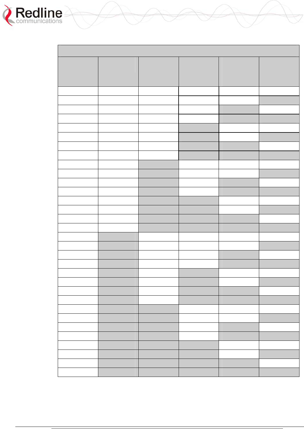
AN-30e
user manual
70-00035-01 Proprietary Redline Communications © 2004 November 2004
Page 72 of 104
Table 33: RF Status Error Codes
Error Code Terminal
PLL Error
Comm
Error Over
IF Cable
Radio
High Temp.
Warning
Radio
Power
Supply
Fault
Low DC
Voltage At
Radio Input
0 No Errors No Errors No Errors No Errors No Errors
1
X
2
X
3
X X
4
X
5
X X
6
X X
7
X X X
8 X
9 X
X
10 X X
11 X X X
12 X X
13 X X X
14 X X X
15 X X X X
16 X
17 X
X
18 X
X
19 X
X X
20 X X
21 X X X
22 X X X
23 X X X X
24 X X
25 X X
X
26 X X X
27 X X X X
28 X X X
29 X X X X
30 X X X X
31 X X X X X

AN-30e
user manual
70-00035-01 Proprietary Redline Communications © 2004 November 2004
Page 73 of 104
7.4 System Error Log Messages
The following table provides a brief description of the key messages recorded in the
logs by the system.
Table 34: System Log Messages
Log Message Description
100-Parameters loaded
successfully!
All system parameters have been successfully downloaded.
101-Firmware configuration OK! The onboard firmware configuration has been properly set
up.
102-Ethernet port configured! The Ethernet port has been properly configured and is
operational.
103-Parameters saved
successfully!
The latest configuration parameters have been successfully
saved into the system memory.
104-Upgrade OK! The software upgrade process completed successfully.
105-Password changed
successfully!
The system password was successfully changed.
106-Firmware programmed OK! The firmware was successfully programmed.
107-Statistics initialized! Reset of statistics was successful.
108-Version control loaded
successfully!
Software version control data was successfully loaded.
109-Options Key activated! Product Options Key was accepted.
110-Options Key already used! The Product Options Key was not accepted because it was
already used once. Contact your local Redline
representative.
111-SNMP configuration loaded
successfully!
The SNMP configuration was successfully loaded.
201-EEPROM corrupted. Def.
param. loaded!
The memory area containing the system configuration has
been corrupted. Default parameters loaded.
202-Error while saving
parameters!
The latest configuration parameters have not been
successfully saved. In this case, repeat the save
configuration process to try to resolve the problem.
203-Another upgrade in
progress!
The system is already in upgrade mode, in the event the
operator inadvertently invoked multiple simultaneous
upgrades.
204-Invalid upgrade parameters! The parameter entered is in error. If this message appears,
check for typing errors.
205-Upgrade failed! The software upgrade process completed unsuccessfully.
206-Password changed
unsuccessfully!
The new password entered into the system was not
successful. In this case, repeat the process.
207-Timeout on reading data
packet!
The system has timeout looking for packets from the host
computer or server. Check for obvious problems such as
disconnected or faulty cable.
209-TFTP error received! The Trivial File Transfer Protocol (TFTP) routine used to
download the software to the terminal during the Upgrade
process failed. The most likely cause is a disconnected or
faulty cable.
210-Error: TFTP unknown
message!
The TFTP client received an unknown message. In this
case, repeat the upgrade process.

AN-30e
user manual
70-00035-01 Proprietary Redline Communications © 2004 November 2004
Page 74 of 104
Table 34: System Log Messages
Log Message Description
211-Error: while writing flash!
While writing the new software into terminal flash memory,
an unexpected error occurred. Try to repeat the process and
if the error persists, contact your local representative.
212-Error firmware configuration! An unexpected error occurred while writing the onboard
firmware configuration. Try to repeat the process.
213-Firmware programming
failed!
The firmware programming failed.
214-Error while loading version
control!
Software version control data was not loaded successfully.
215-Log buffer full! The log buffer overflowed.
216-Invalid Options Key! User entered an invalid Product Options key.
217- PLL unlocked! One or more RF synthesizers unlocked. The unit stopped
RF transmissions and attempted to reprogram the
synthesizers. If this message repeats or if the RF link is not
back on, try to reset the terminal. If the problem persists,
contact customer support.
218-Outdoor unit over
temperature!
The internal temperature of the transceiver is above 185F /
85C. The transceiver shuts down for thirty seconds to allow
cooling.
219-Excessive DC loss on IF
cable!
The DC voltage at the transceiver (carried by the IF cable
from the terminal) is lower than the required 24 VDC. Check
the IF cable and connectors.
220-Outdoor unit power supply
fault!
Displays a fault in the transceivers power supply. This error
could be due to a problem with the internal power supply, or
with the power source from the terminal. If error 219
(Excessive DC loss on IF cable) is also indicated, check the
IF cable and connectors. Otherwise, the transceiver requires
servicing.
221-\public\ community cannot
be deleted!
The default Public SNMP community cannot be deleted.
222-Max. community number
already defined!
No more communities may be defined, as the maximum
number has been reached
223-Community name already
defined!
The name for the SNMP community has already been used.
Choose another name.
224-MIB initialization error! MIB construction process generated an error. Try to reset
the terminal. If the problem persists, contact customer
support.
225-Error while loading SNMP
configuration!
EEPROM memory was corrupted and the SNMP
configuration could not be loaded. Default SNMP
configuration was loaded.
226-Error while saving SNMP
configuration!
SNMP configuration saving process was not successfully.
Try again. If the problem persists, contact customer support.
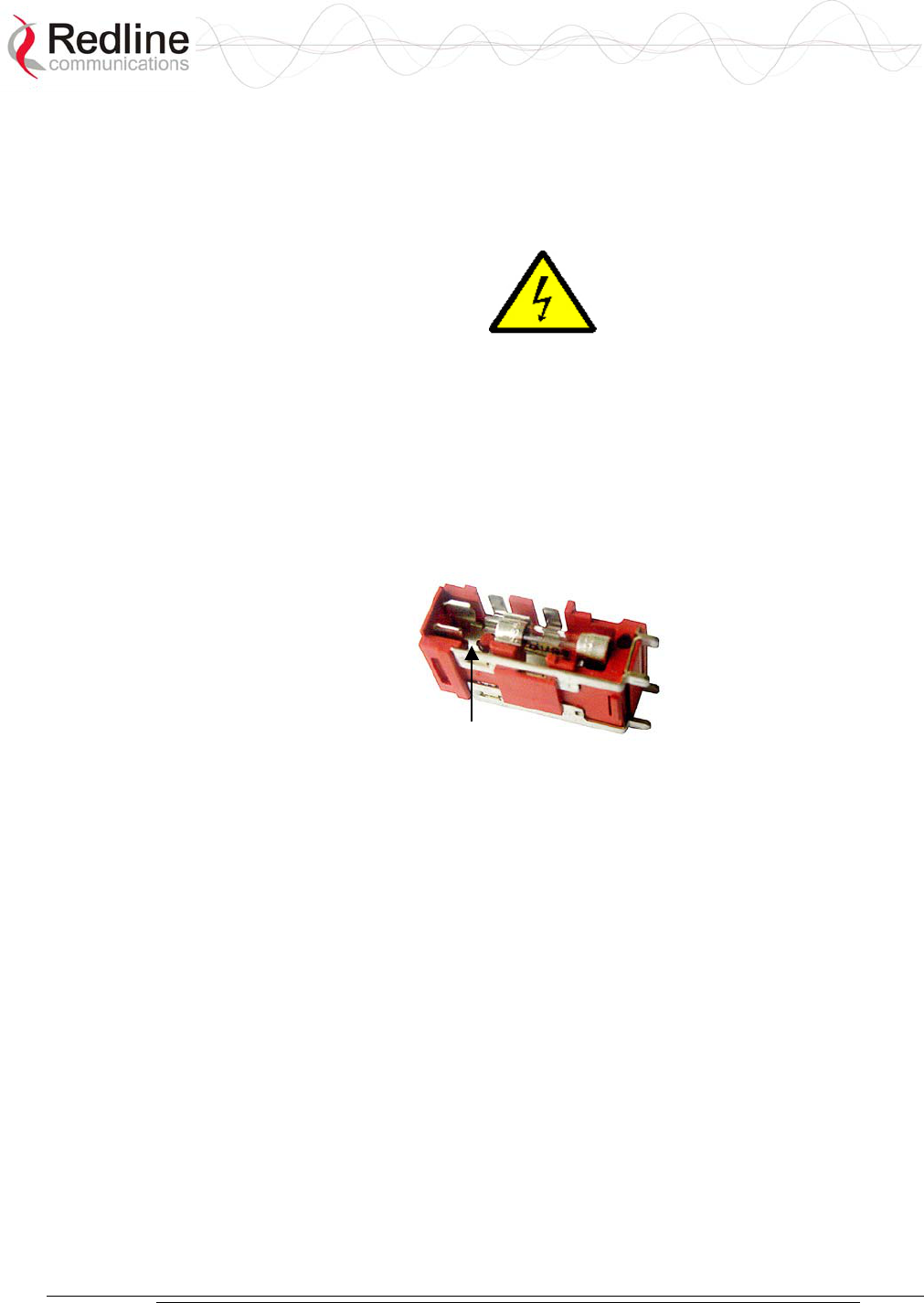
AN-30e
user manual
70-00035-01 Proprietary Redline Communications © 2004 November 2004
Page 75 of 104
7.5 Replacing System Fuse
IMPORTANT: Always completely remove power from the AN-30e system before
performing any maintenance on the terminal or transceiver.
To replace fuse:
1. Disconnect power from the terminal.
2. Pry off the black plastic cover located on the back panel beside the power switch
and extract the red fuse holder.
3. Use an approved tool to remove the glass-cased fuses from the holder.
Be certain to replace the fuse(s) into the lower half of the holder, as shown in the
diagram below. The fuse holder holds two fuses, both of which are active. Be
certain to use fuses of the same type and rating.
Note space
Figure 39: Fuse Holder
4. Replace the fuse holder in the system terminal and secure.
5. Restore power to the AN-30e system.

AN-30e
user manual
70-00035-01 Proprietary Redline Communications © 2004 November 2004
Page 76 of 104

AN-30e
user manual
70-00035-01 Proprietary Redline Communications © 2004 November 2004
Page 77 of 104
Chapter
8
8
8
A
Ap
pp
pe
en
nd
di
ix
x
8.1 System Specifications
Table 35: AN-30e Technical Specifications
Wireless System
System Capability: LOS, Optical-LOS, and Non-LOS
RF Band: T-54 Radio: 5.470 GHz to 5.725 GHz
T-58 Radio: 5.725 GHz to 5.825 GHz
T-58e Radio: 5.725 GHz to 5.850 GHz
Center Frequency Steps: 5 MHz1
Channel Size: 20 MHz
RF Dynamic Range: > 50 dB
Data Rate: Up to 44 Mbps average Ethernet rate (varies with
TDM activity)
Max TX Power: -20 dBm to 20 dBm (region specific)2
Rx Sensitivity: -86 dBm @ 6 Mbps (based on BER of 1x10e-9)
IF Cable: Multiplexed IF, DC, control (Tx/Rx, AGC, APC), Up to
76 m (250 ft) using RG-6U cable3, Up to 228 m (750
ft) using high-grade cable3
Network Attributes: 802.1p network traffic prioritization, 802.3x Ethernet
flow control, Automatic Link Distance Ranging, DHCP
pass through, Transparent bridge, VLAN pass through
Dynamic Channel Control: Dynamic Frequency Selection (DFS), Automatic
Transmit Power Control (ATPC)
Modulation/Coding Rates: Adaptive Modulation (bi-directional burst to burst) auto
selects: 1/2 BPSK, 3/4 BPSK, 1/2 QPSK, 3/4 QPSK,
1/2 16 QAM,
3/4 16 QAM, 2/3 64 QAM and 3/4 64 QAM
Over The Air Encryption: 64-bit private key encryption
MAC: Point-to-Point and Point-to-Multipoint deployment,
TDMA, Concatenation, Automatic Repeat Request
(ARQ) error correction, Dynamic adaptive modulation
(BPSK to 64 QAM)
Range: Over 25 km (15 miles) line-of-sight @ 33 dBm EIRP
(for Europe), Over 80 km (50 miles) line-of-sight @ 48
dBm EIRP
Network Services: Framed/unframed, full/fractional E1 trans
p
ort,

AN-30e
user manual
70-00035-01 Proprietary Redline Communications © 2004 November 2004
Page 78 of 104
Table 35: AN-30e Technical Specifications
Transparent to 802.3 services and applications
Duplex Technique: Dynamic TDD (time division duplex)
Wireless Transmission: OFDM (orthogonal frequency division multiplexing)
Network Connections: E1 transport: framed and unframed, full and fractional
(RJ-48c), 10/100 Ethernet (RJ-45)
System Configuration: HTTP (Web) interface, SNMP, CLI via Telnet/console
Network Management: SNMP: standard and proprietary MIBs, Full
management by RedAccess NMS
Power Requirements: Single/dual auto-sensing 110/220/240 VAC 50/60 Hz,
Single/dual 18 VDC to 72 VDC, 49 W maximum,
Redundant Power: Optional dual AC or dual DC power supply (dual cord)
with automatic fail-over
Compliance: EN 60950, EN 301 893, EN 301 390, EN 301 489-1 &
17, FCC part 15
Operating Temperature: IDU Operating Cond.: 5 C to 40 C,
IDU Short-Term Cond.: -5 C to 55 C for up to 16 hours
ODU Operating Cond.: -40 C to 60 C
Dimensions: IDU: 431.8 mm x 304.8 mm x 44.45 mm (17" x 12" x
1.75")
Weight: 2.5 Kg (5.5 lb)
TDM Specifications:
Clocking: Adaptive/loopback/internal
Diagnostics: Remote loop and local loop testing, detects and
generates LOS, AIS and RAI
Interface Ports: One to eight TDM ports, supports Fractional nx64
Services
Jitter Buffering: 5-300 milliseconds
Round Trip Delay (RTD): Less than ten milliseconds
Line Length: 2000 m using 22 AWG twisted pair cable
E1 Interfaces:
Connector: RJ-48c
Data Rate: 2.048 Mbps
Framing: Unframed, CRC4, FAS/MFAS
Jitter: ITU-T G.823
Line Code: HDB3, AMI
Line Impedance: Balanced 120 Ohm
Line Protection: ITU-T K-20, K-21
Standards: ETS TBR 12/13, ITU-T Rec., G.703, G.704, G.706,
G.732, G.821, G.826
T1 Interfaces
Connector: Balanced RJ-48c
Data Rate: 1.544 Mbps
Framing: Unframed, D4 (SF), ESF
Jitter: AT&T TR-62411, ITU-T G.824

AN-30e
user manual
70-00035-01 Proprietary Redline Communications © 2004 November 2004
Page 79 of 104
Table 35: AN-30e Technical Specifications
Line Build-out: 0 dB, -7.5 dB, -15 dB, –22.5 dB
Line Code: AMI, B8ZS
Line Impedance: Balanced 100 ohm
Line Protection: Bellcore GR 1089
Standards: ANSI T1.403, ITU-T Rec. G.703, G.704, G.733,
G.821, G.826
1Center frequency is dependent on region.
2In some countries outside of North America, the maximum operational power per
channel with a given antenna is limited in accordance to maximum allowable EIRP
levels for the region.
3With two lightning arrestors installed.
Subject to change without notice.
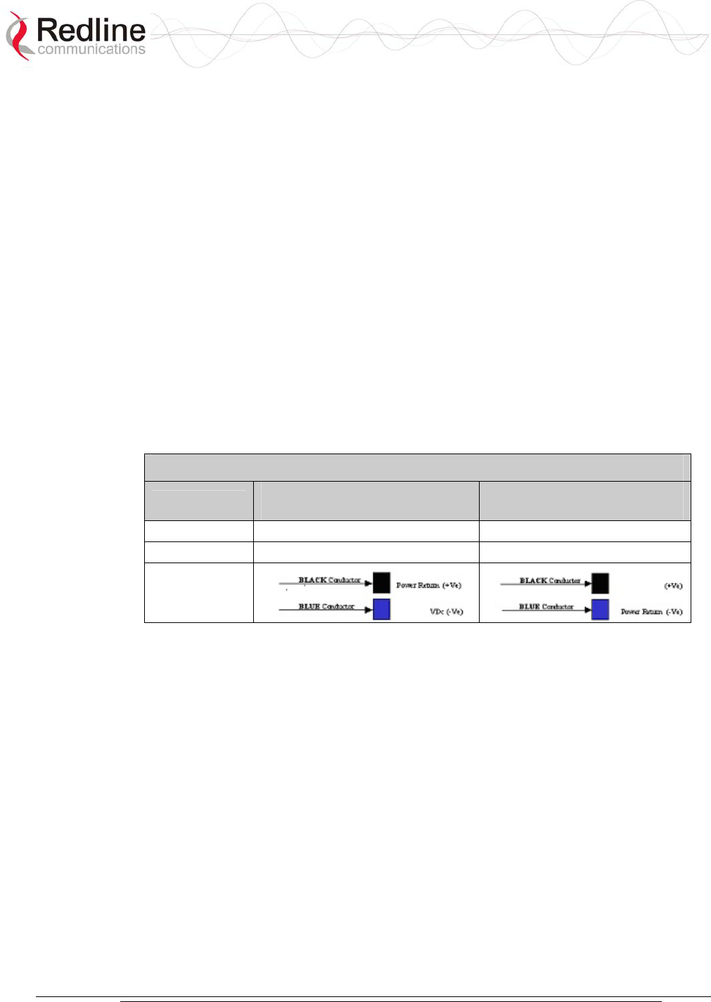
AN-30e
user manual
70-00035-01 Proprietary Redline Communications © 2004 November 2004
Page 80 of 104
8.2 DC Power Supply Cable Connections
This section provides important instructions for connecting to a DC power source.
The optional DC power supply is rated for operation over a range from 18 VDC to 72
VDC. Power is connected to the terminal via a fused power entry module located on
the rear of the terminal. All DC terminals are shipped with a power cord assembly,
consisting of the power entry modules mating dual pin polarized female plug, pre-
crimped with 18 AWG blue and black insulated wires. All power wiring must be at
least 18 AWG.
The DC power input is floating (+Ve and -Ve not connected to chassis), allowing
positive (minus to ground), negative (positive to ground) and floating power
connections as required. Refer to table below for connection details.
If the terminal does not power-on, it is possible that the blue and black wires are
connected incorrectly resulting in a reversal of polarity. In this event, the diode
protection prevents permanent damage to the power supply. Reverse the power
connections and verify that the terminal powers up properly.
Table 36: DC Power Supply Cable Connections
Wire Color Negative DC Power
(-18 to -72 VDC)
Positive DC Power
(+18 to +72 VDC)
Blue Negative power Power Return
Black Power Return Positive Power
Schematics
Note: DC units are not equipped with power switches and activate immediately when
connected to a power source.

AN-30e
user manual
70-00035-01 Proprietary Redline Communications © 2004 November 2004
Page 81 of 104
8.3 Antenna and Power Specifications
8.3.1 T-58 Radio: Antenna Power Specifications
The system is FCC certified for the antennas listed in the following table.
Table 37: T-58 Radio: Antenna Power Specifications
Redline
P/N
Ant.
Gain
(dBi)
Antenna
Type Appl.
Minimum
Conducted
Power
(dBm)
Max
Conducted
Power
Ratings
(dBm)
Average
GUI
Power
Display
(dBm)
FCC
Max
EIRP
(dBm)
48-00006 28 Directional
Flat Panel PTP -20 26 20 No
Limit
48-00020 23 Directional
Flat Panel PTP -20 26 20 No
Limit
48-00030 22 Directional
Parabolic PTP -20 26 20 No
Limit
48-00031 28 Directional
Parabolic PTP -20 26 20 No
Limit
48-00032 31.2 Directional
Parabolic PTP -20 26 20 No
Limit
48-00033 34.6 Directional
Parabolic PTP -20 26 20 No
Limit
48-00006 28 Directional
Flat Panel PMP -20 8 2 36
48-00014 15 Directional,
Flat Panel PMP -20 21 15 36
48-00017 14 Directional,
Flat Panel PMP -20 22 16 36
48-00020 23 Directional
Flat Panel PMP -20 13 7 36
48-00028 17 Directional,
Flat Panel PMP -20 19 13 36
48-00029 16 Directional,
Flat Panel PMP -20 20 14 36
48-00030 22 Directional
Parabolic PMP -20 14 8 36
48-00031 28 Directional
Parabolic PMP -20 8 2 36
48-00032 31.2 Directional
Parabolic PMP -20 4 -2 36
48-00033 34.6 Directional
Parabolic PMP -20 1 -5 36
Note: The RF output power and selection must be professionally programmed and
installed by the manufacturer or a trained professional installer for compliance with
FCC requirements of maximum EIRP of 36 dBm.

AN-30e
user manual
70-00035-01 Proprietary Redline Communications © 2004 November 2004
Page 82 of 104
8.3.2 T-58e Radio: Antenna Power Specifications
The system is FCC certified for the antennas listed in the following table.
Table 38: T-58e Radio: Antenna Power Specifications
Redline P/N Ant. Gain
(dBi)
Antenna
Type Appl.
Minimum
Conducted
Power
(dBm)
Max
Conducted
Power
Ratings
(dBm)
Average
GUI Power
Display
(dBm)
FCC Max
EIRP
(dBm)
48-00006 28
Directional
Flat Panel PTP -12.7 26.2 20 No Limit
48-00020 23
Directional
Flat Panel PTP -12.7 26.2 20 No Limit
48-00020-
01 22 Directional
Flat Panel PTP -12.7 26.2 20 No Limit
48-00030 22
Directional
Parabolic PTP -12.7 26.2 20 No Limit
48-00031 28
Directional
Parabolic PTP -12.7 26.2 20 No Limit
48-00032 31.2
Directional
Parabolic PTP -12.7 26.2 20 No Limit
48-00033 34.6
Directional
Parabolic PTP -12.7 26.2 20 No Limit
48-00006 28
Directional
Flat Panel PMP -12.7 8 2 36
48-00014 15
Directional,
Flat Panel PMP -12.7 21 15 36
48-00017 14
Directional,
Flat Panel PMP -12.7 22 16 36
48-00020 23
Directional
Flat Panel PMP -12.7 13 7 36
48-00020-
01 22 Directional
Flat Panel PMP -12.7 14 8 36
48-00028 17
Directional,
Flat Panel PMP -12.7 19 13 36
48-00029 16
Directional,
Flat Panel PMP -12.7 20 14 36
48-00030 22
Directional
Parabolic PMP -12.7 14 8 36
48-00031 28
Directional
Parabolic PMP -12.7 8 2 36
48-00032 31.2
Directional
Parabolic PMP -12.7 4 -2 36
48-00033 34.6
Directional
Parabolic PMP -12.7 1 -5 36
48-00047 15
Directional
Flat Panel PMP -12.7 21 15 36
48-00048 9 Omni-
Directional PMP -12.7 27 20 36
Note: The RF output power and selection must be professionally programmed and
installed by the manufacturer or a trained professional installer for compliance with
FCC requirements of maximum EIRP of 36 dBm.

AN-30e
user manual
70-00035-01 Proprietary Redline Communications © 2004 November 2004
Page 83 of 104
8.3.3 T-54 Radio: Maximum RF Power vs. Antenna Gain
The following table provides the adjustment available for maximum RF power
settings based on the angle of deployment. Applies to sectorized antennas only.
Table 39: 5.4 GHz Band RF Power vs. Antenna Gain
Angle
(Degrees)
A6017 RWS
(dBm)
A9016 RWS
(dBm)
A6015 MTS
(dBm)
A9014 MTS
(dBm)
0 -1 0 4 2
1 0 1 5 3
2 1 4
3 5
4 6
...
12 2
13 3
14 4
15 5
...
24 6
25 2
26 3
27 4 6
28 5 7
29 6 8
...
32 7
37 8
39 9
...
45 7

AN-30e
user manual
70-00035-01 Proprietary Redline Communications © 2004 November 2004
Page 84 of 104
8.3.4 T-54 Radio: Operational Power (FCC)
The following table provides the maximum RF power settings based on the gain of
the antenna.
Table 40: 5.4 GHz -- Antenna Gain vs. Max. Op. Power
Ant. Gain
(dBi)
Max. Power
(dBm)
Ant. Gain
(dBi)
Max. Power
(dBm)
6.0 15 21.0 -1
6.5 15 21.5 -1
7.0 14 22.0 -2
7.5 14 22.5 -2
8.0 13 23.0 -3
8.5 13 23.5 -3
9.0 12 24.0 -4
9.5 12 24.5 -4
10.0 11 25.0 -5
10.5 11 25.5 -5
11.0 10 26.0 -6
11.5 10 26.5 -6
12.0 9 27.0 -7
12.5 9 27.5 -7
13.0 8 28.0 -8
13.5 8 28.5 -8
14.0 7 29.0 -9
14.5 7 29.5 -9
15.0 5 30.0 -9
15.5 5 30.5 -10
16.0 4 31.0 -10
16.5 4 31.5 -11
17.0 3 32.0 -11
17.5 3 32.5 -12
18.0 2 33.0 -12
18.5 2 33.5 -13
19.0 1 34.0 -13
19.5 1 34.5 -14
20.0 0 35.0 -14
20.5 0
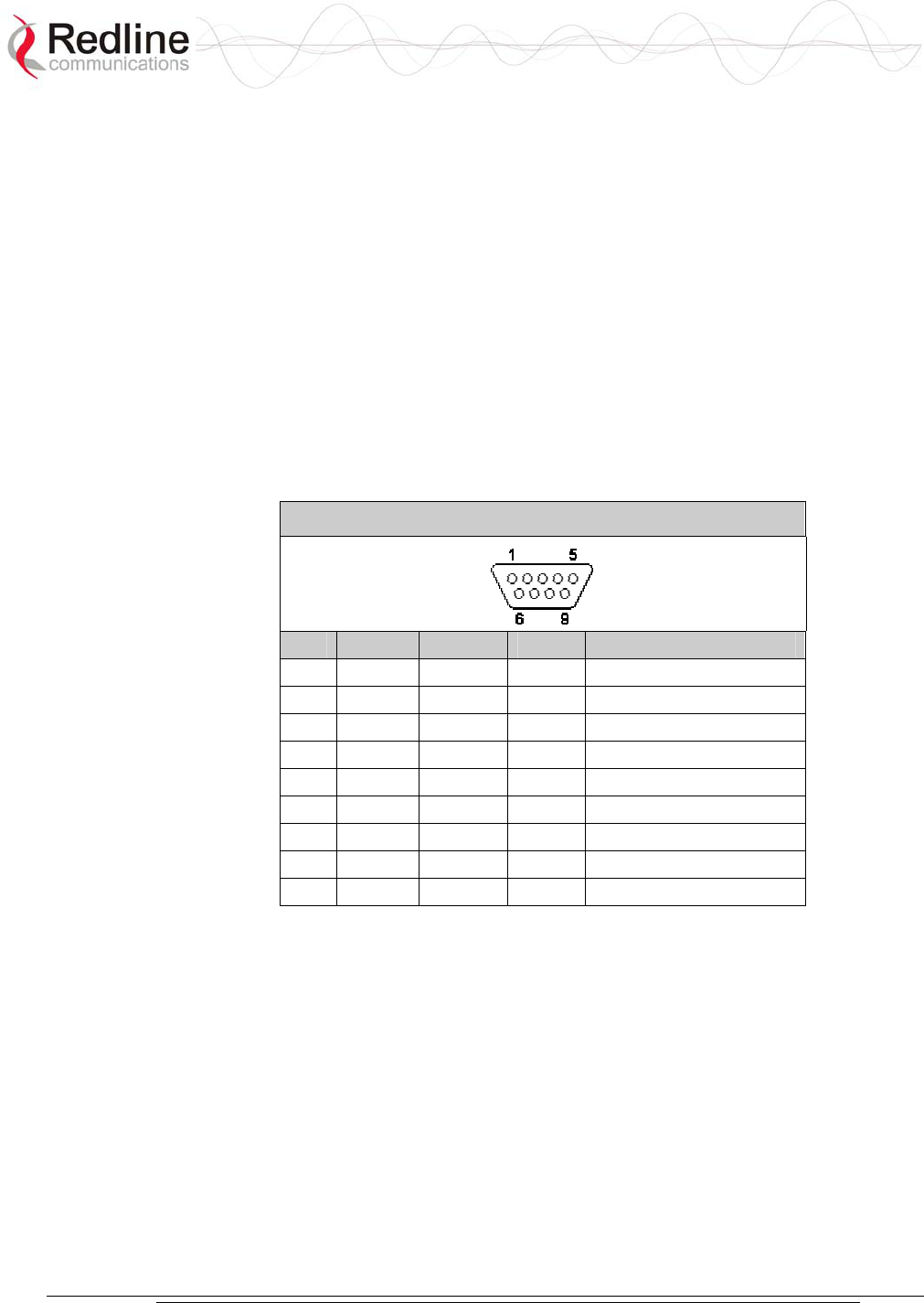
AN-30e
user manual
70-00035-01 Proprietary Redline Communications © 2004 November 2004
Page 85 of 104
8.4 CLI Interface
8.4.1 Console (RS-232) Port
All operator communications with the terminal may be made using a direct
connection to the serial Console Port on the back of the terminal. This section
describes the procedures for configuring and operating the terminal via the Console
Port using the command line interface (CLI).
Connect a PC/Terminal to the terminal serial port DB9 connector using a cross-
connect or null modem cable (DB9 female-female). Set the PC/Terminal to emulate a
VT-52 or VT-100 terminal, using the following port settings: Bits Per Second: 9600;
Data Bits: 8; Parity: None; Stop Bits: 1; Flow Control: Hardware
The following table lists the terminal 9 PIN D-SUB male connector pinout.
Table 41: Console (RS-232) Port Pinout
Pin Name RS232 V.24 Description
1 CD CF 109 Carrier Detect
2 RXD BB 104 Receive Data
3 TXD BA 103 Transmit Data
4 DTR CD 108.2 Data terminal Ready
5 GND AB 102 System Ground
6 DSR CC 107 Data Set Ready
7 RTS CA 105 Request to Send
8 CTS CB 106 Clear to Send
9 RI CE 125 Ring Indicator
V.24 column is ITU-TSS V.24 circuit name.
RS232 column is RS232 circuit name.
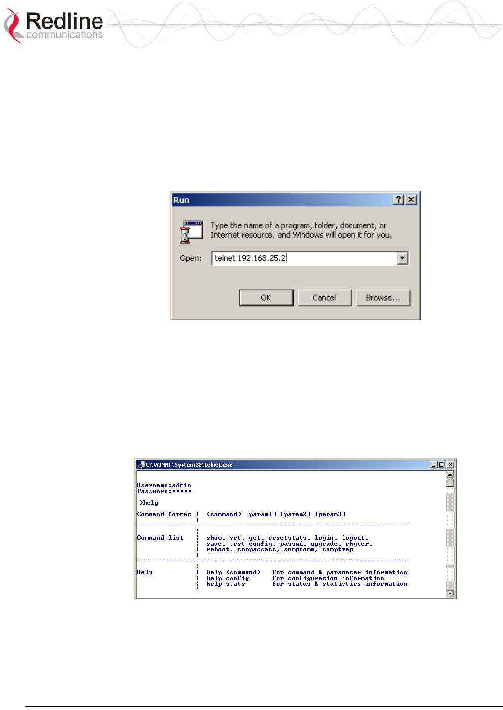
AN-30e
user manual
70-00035-01 Proprietary Redline Communications © 2004 November 2004
Page 86 of 104
8.4.2 Connecting via Telnet
All operator communications with the terminal may be made using CLI over Telnet.
This offers the advantage of allowing the operator to access and control the terminal
remotely from any geographical location, without the need for a web browser. This
section describes the procedures for configuring and operating the terminal via Telnet
using the command line interface (CLI).
To connect to the terminal, Telnet to the IP address of the terminal (default address
shown below).
Figure 40: Connecting via Telnet
When the command prompt screen appears, login using the Username: admin and
Password: admin. The terminal may now be configured and queried using a set of
CLI commands. Type 'help' for a list of general commands.
8.4.3 CLI Commands
The following commands are available via Telnet and Console connections to the
terminal. For online help, type 'help <command>' at the command prompt.
Figure 41: CLI Help Screen

AN-30e
user manual
70-00035-01 Proprietary Redline Communications © 2004 November 2004
Page 87 of 104
General Commands
Table 42: CLI - General Commands
Command Description
chgver Swaps the operating and secondary software versions
get Get <parameter name> displays the value for a status
parameter. For configuration parameters, use Set command.
login Allows login under a different username and password
logout Disconnects user from the terminal.
passwd Change password for user.
passwd <username> <newpassword>
reboot Reboots the terminal. Reboot <time in seconds>
resetstats Resets all statistics
save config Permanently saves system configuration settings. This
command is required to activate all Configuration settings
set previously
save snmp Permanently saves SNMP configuration settings. This
command is required to activate all SNMP settings set
previously.
set Set one configuration parameter:
<parameter name> [<value>]
Without <value>, ‘set’ returns the actual value for
configuration parameters. For status parameters, use the
Get command.
show config Returns a list of all System Configuration parameters.
show log Returns a list of current system log entries.
show snmp Returns a list of all SNMP communities and settings.
show stats Returns a list of all System Status parameters.
snmpaccess Modify access rights for a community (see snmpcomm)
snmpaccess <community name> <access>
snmpcomm To add a new SNMP community:
snmpcomm add <community name> <access>
<access> can be: r,w,t or any combination
To delete an SNMP community
snmpcomm del <community name>
snmptrap To add a trap destination for an SNMP community:
snmptrap add <community name> <IP destination>
To delete a trap destination for an SNMP community:
snmptrap del <community name> <IP destination>
test config Allows testing of configuration settings for 5 minutes,
after which the system reverts to the previously saved
settings. To make settings permanent use 'save' command.
upgrade Begin a software upload.
upgrade <ipaddr> <filename>
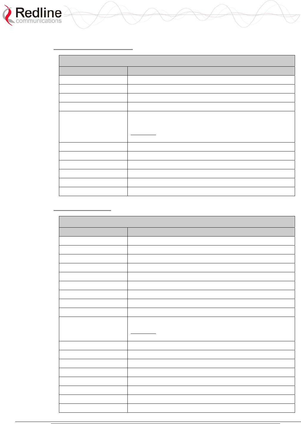
AN-30e
user manual
70-00035-01 Proprietary Redline Communications © 2004 November 2004
Page 88 of 104
General Information
Table 43: CLI - General Information Commands
Command Description
gateway The IP address of the default router
ipaddr The IP address used by the local terminal
ipmask The IP Subnet Mask used by the local terminal
macaddr The Ethernet MAC address used by local terminal
master Displays whether the system is operating as the sector
controller.
Important: For each set of Systems, only one terminal must
be designated Master.
rflink Yes: RF link up / No: RF link down
starttime The time elapsed since the system started
swver The operating software version
sysdetails The location, telephone #, contact information, etc.
sysname Identifies the local terminal
ubrate Displays the current uncoded burst rate
System Status
Table 44: CLI - System Status
Command Description
cableattn The attenuation of the signal over the IF cable
erxpkt Total packets successfully received locally
erxpktd Total packet errors received locally
etxpkt Total Ethernet packets transmitted
gateway The IP address of the default router
ipaddr The IP address used by the local terminal
ipmask The IP Subnet Mask used by the local terminal
ll Actual length of the path that the wave travels.
macaddr The Ethernet MAC address used locally
master Displays if the system is serving as the sector controller.
Important: For each set of Systems, only one terminal must
be designated Master.
resetstats Resets all statistics
rffreq The center frequency of the channel in use
rflink Yes: RF link up. No: RF link down
rfstatus An error code (0-31), indicating the RF status
rssimax The maximum received signal strength
rssimean The average received signal strength
rssimin The minimum received signal strength
sinadr The number of successful wireless
p
ackets received over

AN-30e
user manual
70-00035-01 Proprietary Redline Communications © 2004 November 2004
Page 89 of 104
Table 44: CLI - System Status
Command Description
the air
swver The operating software version
sysname Identifies the local terminal
txpower The actual current transmit power level
wrxpkt The number of successful wireless packets received over
the air
wrxpktd The number of wireless packets received with errors over
the air
wrxpktr The number of wireless packets retransmitted over the air
wtxpkt The number of wireless packets successfully transmitted
over the air
wtxptd The number of transmitted packets discarded
wtxpktr The number of wireless packets retransmitted over the air
System Configuration
Table 45: CLI - System Configuration
Command Description
adaptmod Enables Adaptive Modulation mode.
buzzer Specifies whether the antenna buzzer is enabled - defaults
to voltage.
chgver Change the operating software version
encrypt Specifies whether over-the-air data encryption is enabled
encryptkey Enter the subscriber terminal MAC address if encryption is
enabled
flowctrl Specifies if flow control is enabled on the Ethernet port
gateway The IP address of the default router
http Specifies whether configuration over HTTP is enabled
ipaddr The IP address used by the local terminal
ipmask The IP Subnet Mask used by the local terminal
llmod Specifies if the link length is calculated automatically or
manually. Available options: off for auto and on for manual.
llmu The current measurements units used for the link length.
Available options: off for miles and on for kilometers.
ll Actual length of the path that the wave travels.
macaddr The Ethernet MAC address used by the local terminal
master Displays whether the system is operating as the sector
controller. Important: For each set of Systems, only one
terminal must be designated Master.
modreduct Used when AdaptMod is disabled.
radio Specifies whether radio transmission is enabled
reboot Reset all statistics and reboot the terminal
rfchannel Available channel options: 1, 1A, 2, 2A, 3, 3A, 4, 4A, 5.
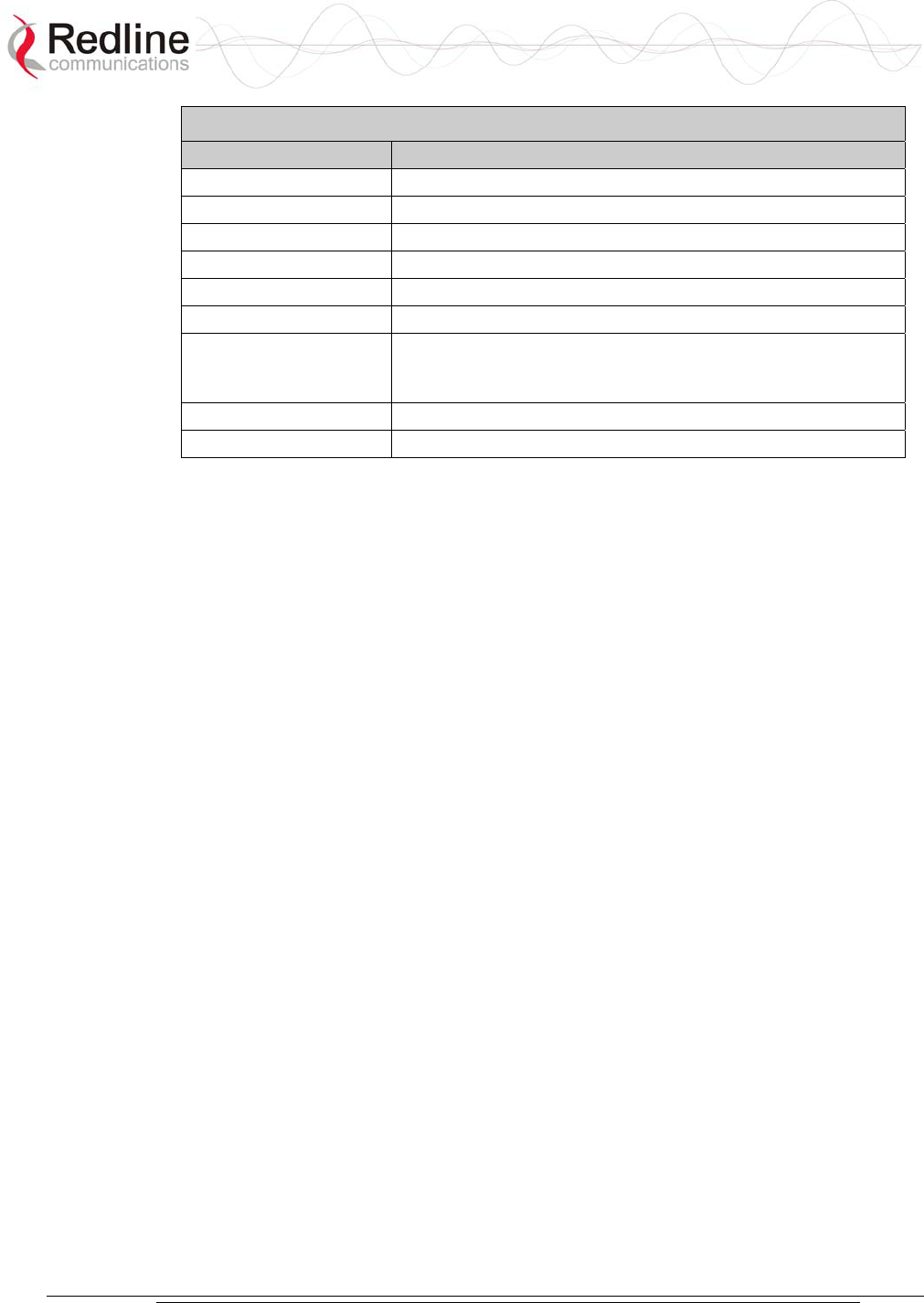
AN-30e
user manual
70-00035-01 Proprietary Redline Communications © 2004 November 2004
Page 90 of 104
Table 45: CLI - System Configuration
Command Description
save config Permanently saves configuration settings
snmp Specifies whether configuration over SNMP is enabled
sysdetails The location, telephone #, contact information, etc.
sysname Identifies the local terminal
telnet Specifies whether configuration over telnet is enabled
telnetport The TCP port used for telnet
test config Allows testing of these settings for 5 minutes, after which the
system reverts to the previously saved settings. Use 'Save'
to make permanently save settings.
txpower The maximum power level of the system
ubrate Sets the desired burst rate for the link.
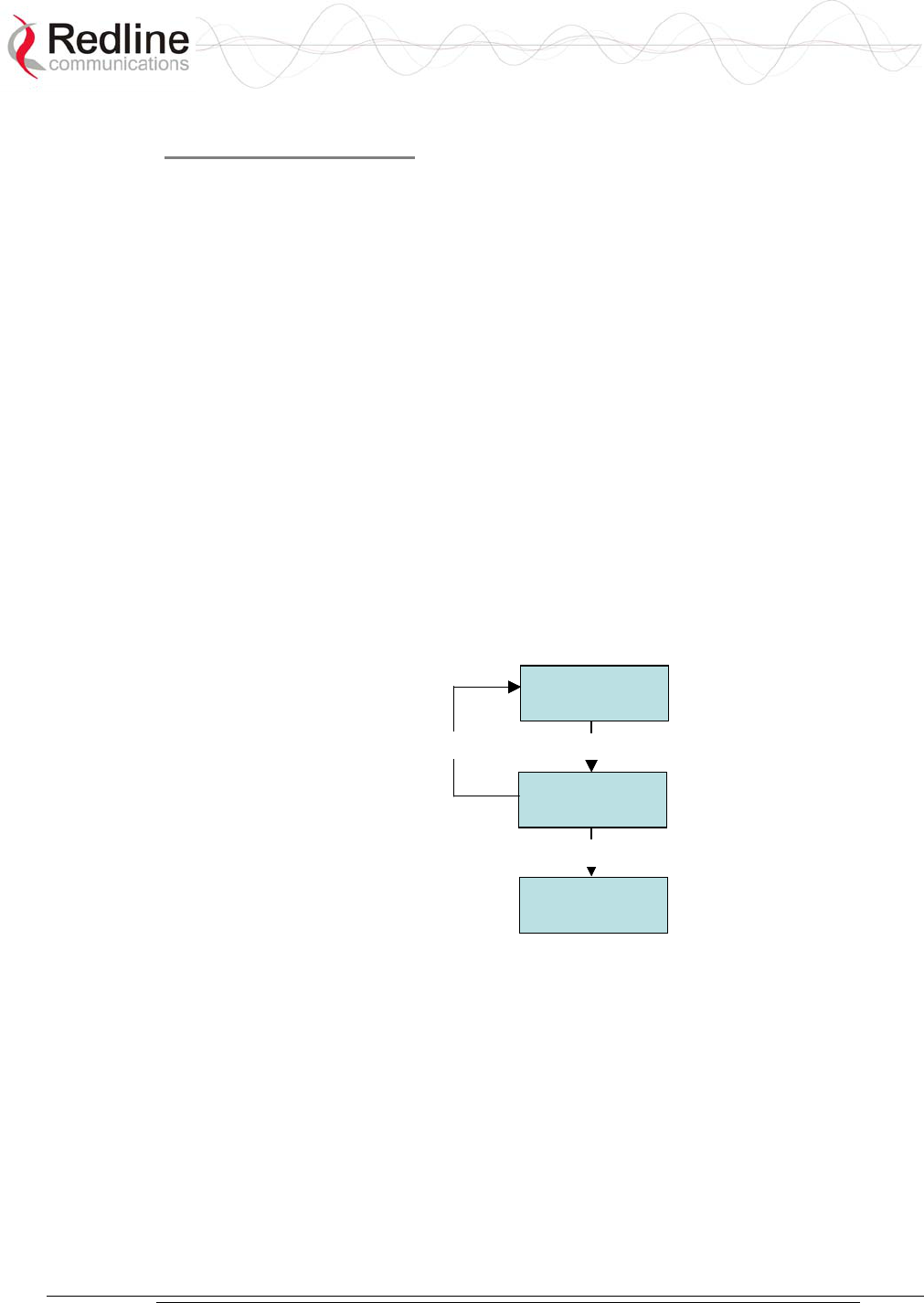
AN-30e
user manual
70-00035-01 Proprietary Redline Communications © 2004 November 2004
Page 91 of 104
TDM CLI Commands
The command line interface can be used to configure the E1 capabilities via the AN-
30e console port or through a telnet session. The CLI command set is divided into
five categories:
1. General
2. Control
3. Serial Interface
4. Bundle
5. Statistics.
Subsequent sections discuss each of these commands in specific detail.
TDM Commands
The AN-30e maintains three TDM configuration images,
- Startup Configuration
- Running Configuration
- Temporary Configuration
These three distinct configuration images allow the operator to edit (temporary) and
test (running) configuration profiles in advance of cutover without losing the default
(startup) configuration settings.
Temporary
Configuration
Running
Configuration
Startup
Configuration
tdm_start tdm_save
tdm_copy
Temporary
Configuration
Running
Configuration
Startup
Configuration
tdm_start tdm_save
tdm_copy
Figure 42: TDM Configuration Files
The control commands are used to manipulate the contents of each of the
configuration images as well as to save and activate a specific configuration. There
are four control commands:
copy: Copy current running configuration into the Startup configuration.
exit: Discard all changes made to the temporary configuration.
save: Copy the temporary configuration image to the running configuration
image.
start: Synchronize the temporary configuration with the running configuration.

AN-30e
user manual
70-00035-01 Proprietary Redline Communications © 2004 November 2004
Page 92 of 104
TDM General Commands
Form of command is:
tdm set command [param1] [param2] [param3]
Table 46: CLI - TDM General Commands
CLI Command Description
clock CLK_IND Clocking mode on E1 module.
fanstate FAN Status of fan.
gateway IPGATEWAY IP address of the default gateway.
hostname HOST Hostname of the E1 module.
ipaddr IP The IP address of the E1 module.
ipmask IP Network mask.
key Option key (permitted line types, number of lines, user data)
on the E1 module.
keyidlecode IDLECODE Idle code for unused timeslots on all of the serial interface
ports.
line LINE_TYPE Line type on the E1 module (if permitted by the option key).
0=T1, 1=E1
showactivebundles Total active bundles and list the IDs of those bundles.
showgen CONFIG General configuration parameters from running or startup
config.
softver Coded software version.
syncon SYNC_ON The serial interface port to be used as clocking reference.
vlandata VID_DATA The VLAN ID used to tag all ingress traffic at the data port
of the AN-30e.
vlanvoice VID_VOICE The VLAN ID used to tag all traffic from the E1 ports of the
AN-30e.
TDM Set and Get operations
The get operation returns values from the running configuration. The set operation
applies changes only to the temporary configuration. Use the 'tdm test' command to
try the settings for five minutes or the 'tdm save' command to save the changes
permanently.
All commands are of the following format:
tdm set operator SN <optional parameters>
tdm get operator SN command
Table 47: CLI - TDM Set and Get Commands
CLI Command Description
get Retrieve the parameter value from a running configuration.
set Modify the specified parameter value in the temporary
configuration.
show List all parameter values of the command category.
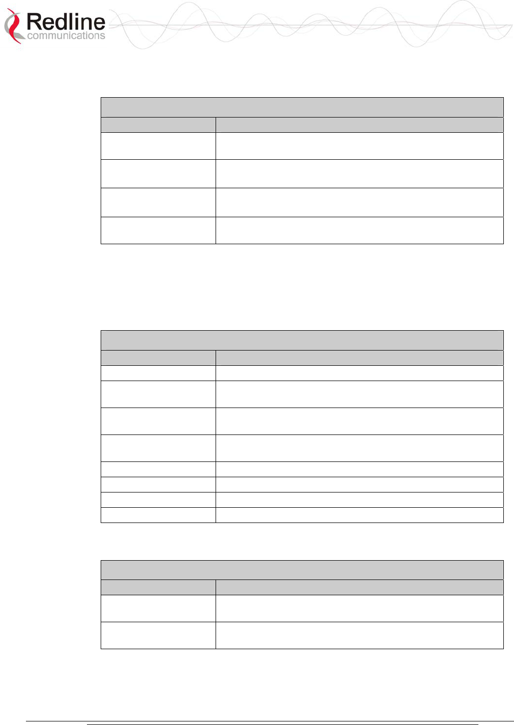
AN-30e
user manual
70-00035-01 Proprietary Redline Communications © 2004 November 2004
Page 93 of 104
TDM Serial Interface Commands
These serial commands are used to configure the E1 ports.
Table 48: CLI - TDM Serial Interface Commands
CLI Command Description
coding SN COD_IND Line coding type for the current serial interface on E1
module. 0=B8ZS, 1=AMI, 2=HDB3
framing SN FRM_IND Framing type of the current serial interface on E1 module.
0=ESF, 1=D4, 2=CRC4, 3=FAS, 4=Unframed
set lbo SN LBO_IND LBO parameter of the current serial interface on T1 module.
0=0 dB, 1= -7.5 dB, 2= -15 dB, 3= -20 dB
showserial SN CFG Serial interface parameters pointed by SN from running or
startup config.
TDM DS0 Bundle Commands
All commands are of the following format::
tdm set operator BN <optional parameters>
tdm get operator BN command
Table 49: CLI - TDM DS0 Bundle Commands
CLI Command Description
delbundle Delete all settings of specified bundle.
destbundle DESTB Identifies the destination bundle that maps to the specified
bundle.
destip BN DEST_IP Identifies the destination IP address (AN-30e) for the
specified bundle.
jitterbuf BN JBLEN This command specifies the jitter buffer length for the
specified bundle.
packetlen BN PLEN Defines the packet length to be used by the specified bundle.
show BN CFG Retrieve bundle parameters for the specified BN.
tsbegin BN TSB First active timeslot of the specified bundle.
tsnum BN TSB Number active timeslots in the specified bundle.
TDM Statistics Commands
Table 50: CLI - TDM General Statistics Commands
CLI Command Description
resetstat STAT This command resets the module specific statistics selected
by STAT.
showstat STAT This command requests the module specific statistics
selected by STAT.
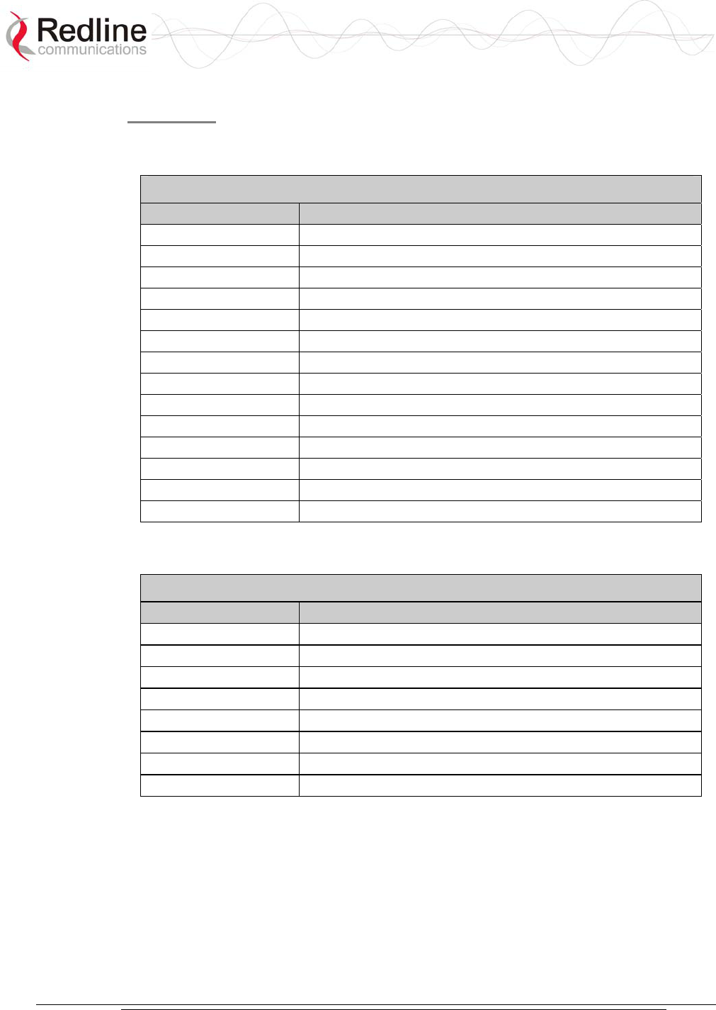
AN-30e
user manual
70-00035-01 Proprietary Redline Communications © 2004 November 2004
Page 94 of 104
Statistics
The following tables describe the statistics available from the AN-30e.
Ethernet Statistics
Table 51: CLI - TDM Ethernet Statistics Commands
Statistic Description
ethpmac MAC Address
ethpmode Mode: 0-Half Duplex, 1-Full Duplex
ethprate Rate: 0-10 Mbps, 1-100 Mbps
ethpstate State: 0-not connected, 1-connected (link up)
ethsaerr Align errors
ethsbtok Bytes transmitted ok
ethscerr CRC errors
ethsfrok Frames transmitted ok
ethslcol Late collisions
ethsmcol Multiple collisions
ethsmfrok Frames received ok
ethsscol Single collisions
ethstdef Transmission deferred
tdethsbrok Bytes received ok
TDM Statistics
Table 52: CLI - TDM Statistics
Statistic Description
tdmsais SN Alarm indication signal
tdmscvc SN Code violation counter
tdmses SN Errored seconds
tdmsfec SN Framing error counter
tdmslfa Loss of framing alignment
tdmslomf Loss of multi framing
tdmslos Loss of signal
tdmsrai SN Subscriber alarm indication

AN-30e
user manual
70-00035-01 Proprietary Redline Communications © 2004 November 2004
Page 95 of 104
TDM Save Command Error Codes
The error code returned by an unsuccessful save command contains three fields:
LEVEL + NUMBER + ERROR_ID
Table 53: TDM Save Command Error Codes
Level Number Error
ID Definition
0
GENERAL_SYNCON
Too many bundles: if user defines more than
the internal bundle limit for the current
software release
1 GENERAL_TOO_MANY_BUNDLES
Line type (T1 or E1) is disabled in option key
0
(General)
Always 0
2
GENERAL_LINE_TYPE
Error at syncon parameter: if clocking is
loopback and the serial interface selected for
synchronization has no bundles defined, or if
clocking is adaptive and there is no exactly
one bundle defined
0
SERIAL_BUNDLES_OVERLAP
Bundles defined on the serial line 'x' have
timeslots overlapping, x=1…4
1
SERIAL_TOO_MANY_BUNDLES
The serial line 'x' is unframed and the user
defined more than one bundle, x=1…4
2
SERIAL_CODING
Wrong line coding for the serial line 'x',
x=1…4
1
(Serial)
x
Number of
misconfigured
serial
interface
(1-4)
3
SERIAL_FRAMING
Wrong line framing for the serial line 'x',
x=1…4
0
BUNDLE_TS0
The bundle 'y' contains timeslot 0 and the
corresponding serial line is framed, y=1…128
2
(Bundle)
y
Number of
the
misconfigured
bundle
(1-128)
1
BUNDLE_MASK
Too many timeslots selected for bundle 'y',
y=1…128

AN-30e
user manual
70-00035-01 Proprietary Redline Communications © 2004 November 2004
Page 96 of 104
8.4.4 Sample TDM CLI Setup Scripts
Example CLI Script -- E1
The following table contains sample CLI command scripts for configuring AN-30e
system with eight E1 interface ports.
Table 54: E1 Framed Configuration Script
Local (Network) End AN-30e System Remote End AN-30e System
tdm start
tdm set line 1
tdm set clock 1
tdm set syncon 1
tdm set idlecode 255
tdm set ipaddr 192.168.100.192
tdm set vlanvoice 3
tdm set coding 1 2
tdm set framing 1 4
tdm set loopback 1 0
tdm set coding 2 2
tdm set framing 2 4
tdm set loopback 2 0
tdm set coding 3 2
tdm set framing 3 4
tdm set loopback 3 0
tdm set coding 4 2
tdm set framing 4 4
tdm set loopback 4 0
tdm set coding 5 2
tdm set framing 5 4
tdm set loopback 5 0
tdm set coding 6 2
tdm set framing 6 4
tdm set loopback 6 0
tdm set coding 7 2
tdm set framing 7 4
tdm set loopback 7 0
tdm set coding 8 2
tdm set framing 8 4
tdm set loopback 8 0
tdm set destbundle 1 1
tdm set tsbegin 1 0
tdm set tsnum 1 32
tdm set destip 1 192.168.100.199
tdm set jitterbuf 1 20
tdm set packetlen 1 256
tdm set destbundle 33 33
tdm set tsbegin 33 0
tdm set tsnum 33 32
tdm set destip 33 192.168.100.199
tdm set jitterbuf 33 20
tdm set packetlen 33 256
tdm start
tdm set line 1
tdm set clock 2
tdm set syncon 1
tdm set idlecode 255
tdm set ipaddr 192.168.100.199
tdm set vlanvoice 3
tdm set coding 1 2
tdm set framing 1 4
tdm set loopback 1 0
tdm set coding 2 2
tdm set framing 2 4
tdm set loopback 2 0
tdm set coding 3 2
tdm set framing 3 4
tdm set loopback 3 0
tdm set coding 4 2
tdm set framing 4 4
tdm set loopback 4 0
tdm set coding 5 2
tdm set framing 5 4
tdm set loopback 5 0
tdm set coding 6 2
tdm set framing 6 4
tdm set loopback 6 0
tdm set coding 7 2
tdm set framing 7 4
tdm set loopback 7 0
tdm set coding 8 2
tdm set framing 8 4
tdm set loopback 8 0
tdm set destbundle 1 1
tdm set tsbegin 1 0
tdm set tsnum 1 32
tdm set destip 1 192.168.100.192
tdm set jitterbuf 1 20
tdm set packetlen 1 256
tdm set destbundle 33 33
tdm set tsbegin 33 0

AN-30e
user manual
70-00035-01 Proprietary Redline Communications © 2004 November 2004
Page 97 of 104
tdm set destbundle 65 65
tdm set tsbegin 65 0
tdm set tsnum 65 32
tdm set destip 65 192.168.100.199
tdm set jitterbuf 65 20
tdm set packetlen 65 256
tdm set destbundle 97 97
tdm set tsbegin 97 0
tdm set tsnum 97 32
tdm set destip 97 192.168.100.199
tdm set jitterbuf 97 20
tdm set packetlen 97 256
tdm set destbundle 129 129
tdm set tsbegin 129 0
tdm set tsnum 129 32
tdm set destip 129 192.168.100.199
tdm set jitterbuf 129 20
tdm set packetlen 129 256
tdm set destbundle 161 161
tdm set tsbegin 161 0
tdm set tsnum 161 32
tdm set destip 161 192.168.100.199
tdm set jitterbuf 161 20
tdm set packetlen 161 256
tdm set destbundle 193 193
tdm set tsbegin 193 0
tdm set tsnum 193 32
tdm set destip 193 192.168.100.199
tdm set jitterbuf 193 20
tdm set packetlen 193 256
tdm set destbundle 225 225
tdm set tsbegin 225 0
tdm set tsnum 225 32
tdm set destip 225 192.168.100.199
tdm set jitterbuf 225 20
tdm set packetlen 225 256
tdm save
tdm copy
tdm set tsnum 33 32
tdm set destip 33 192.168.100.192
tdm set jitterbuf 33 20
tdm set packetlen 33 256
tdm set destbundle 65 65
tdm set tsbegin 65 0
tdm set tsnum 65 32
tdm set destip 65 192.168.100.192
tdm set jitterbuf 65 20
tdm set packetlen 65 256
tdm set destbundle 97 97
tdm set tsbegin 97 0
tdm set tsnum 97 32
tdm set destip 97 192.168.100.192
tdm set jitterbuf 97 20
tdm set packetlen 97 256
tdm set destbundle 129 129
tdm set tsbegin 129 0
tdm set tsnum 129 32
tdm set destip 129 192.168.100.192
tdm set jitterbuf 129 20
tdm set packetlen 129 256
tdm set destbundle 161 161
tdm set tsbegin 161 0
tdm set tsnum 161 32
tdm set destip 161 192.168.100.192
tdm set jitterbuf 161 20
tdm set packetlen 161 256
tdm set destbundle 193 193
tdm set tsbegin 193 0
tdm set tsnum 193 32
tdm set destip 193 192.168.100.192
tdm set jitterbuf 193 20
tdm set packetlen 193 256
tdm set destbundle 225 225
tdm set tsbegin 225 0
tdm set tsnum 225 32
tdm set destip 225 192.168.100.192
tdm set jitterbuf 225 20
tdm set packetlen 225 256
tdm save
tdm copy
Where,
LINE:1=E1
FRAMING:1=D4; 2=CRC4; 3=FAS; 4=Unframed
CODING: 1=AMI; 2=HDB3
LOOPBACK: 0=loopback disable; 1=local; 2=remote; 3=payload

AN-30e
user manual
70-00035-01 Proprietary Redline Communications © 2004 November 2004
Page 98 of 104
Example CLI Script -- T1
The following table contains sample CLI command scripts for configuring an AN-30e
system with eight T1 interface ports.
Table 55: T1 Framed Configuration Script
Local (Network) End AN-30e System Remote End AN-30e System
tdm start
tdm set line 0
tdm set clock 1
tdm set syncon 1
tdm set idlecode 255
tdm set ipaddr 192.168.100.192
tdm set vlanvoice 3
tdm set coding 1 0
tdm set framing 1 4
tdm set lbo 1 0
tdm set loopback 1 0
tdm set coding 2 0
tdm set framing 2 4
tdm set lbo 2 0
tdm set loopback 2 0
tdm set coding 3 0
tdm set framing 3 4
tdm set lbo 3 0
tdm set loopback 3 0
tdm set coding 4 0
tdm set framing 4 4
tdm set lbo 4 0
tdm set loopback 4 0
tdm set coding 5 0
tdm set framing 5 4
tdm set lbo 5 0
tdm set loopback 5 0
tdm set coding 6 0
tdm set framing 6 4
tdm set lbo 6 0
tdm set loopback 6 0
tdm set coding 7 0
tdm set framing 7 4
tdm set lbo 7 0
tdm set loopback 7 0
tdm set coding 8 0
tdm set framing 8 4
tdm set lbo 8 0
tdm set loopback 8 0
tdm set destbundle 1 1
tdm set tsbegin 1 0
tdm set tsnum 1 25
tdm set destip 1 192.168.100.199
tdm set jitterbuf 1 20
tdm set packetlen 1 200
tdm set destbundle 33 33
tdm set tsbegin 33 0
tdm set tsnum 33 25
tdm set destip 33 192.168.100.199
tdm set jitterbuf 33 20
tdm set packetlen 33 200
tdm set destbundle 65 65
tdm set tsbegin 65 0
tdm start
tdm set line 0
tdm set clock 2
tdm set syncon 1
tdm set idlecode 255
tdm set ipaddr 192.168.100.199
tdm set vlanvoice 3
tdm set coding 1 0
tdm set framing 1 4
tdm set lbo 1 0
tdm set loopback 1 0
tdm set coding 2 0
tdm set framing 2 4
tdm set lbo 2 0
tdm set loopback 2 0
tdm set coding 3 0
tdm set framing 3 4
tdm set lbo 3 0
tdm set loopback 3 0
tdm set coding 4 0
tdm set framing 4 4
tdm set lbo 4 0
tdm set loopback 4 0
tdm set coding 5 0
tdm set framing 5 4
tdm set lbo 5 0
tdm set loopback 5 0
tdm set coding 6 0
tdm set framing 6 4
tdm set lbo 6 0
tdm set loopback 6 0
tdm set coding 7 0
tdm set framing 7 4
tdm set lbo 7 0
tdm set loopback 7 0
tdm set coding 8 0
tdm set framing 8 4
tdm set lbo 8 0
tdm set loopback 8 0
tdm set destbundle 1 1
tdm set tsbegin 1 0
tdm set tsnum 1 25
tdm set destip 1 192.168.100.192
tdm set jitterbuf 1 20
tdm set packetlen 1 200
tdm set destbundle 33 33
tdm set tsbegin 33 0
tdm set tsnum 33 25
tdm set destip 33 192.168.100.192

AN-30e
user manual
70-00035-01 Proprietary Redline Communications © 2004 November 2004
Page 99 of 104
Table 55: T1 Framed Configuration Script
Local (Network) End AN-30e System Remote End AN-30e System
tdm set tsnum 65 25
tdm set destip 65 192.168.100.199
tdm set jitterbuf 65 20
tdm set packetlen 65 200
tdm set destbundle 97 97
tdm set tsbegin 97 0
tdm set tsnum 97 25
tdm set destip 97 192.168.100.199
tdm set jitterbuf 97 20
tdm set packetlen 97 200
tdm set destbundle 129 129
tdm set tsbegin 129 0
tdm set tsnum 129 25
tdm set destip 129 192.168.100.199
tdm set jitterbuf 129 20
tdm set packetlen 129 200
tdm set destbundle 161 161
tdm set tsbegin 161 0
tdm set tsnum 161 25
tdm set destip 161 192.168.100.199
tdm set jitterbuf 161 20
tdm set packetlen 161 200
tdm set destbundle 193 193
tdm set tsbegin 193 0
tdm set tsnum 193 25
tdm set destip 193 192.168.100.199
tdm set jitterbuf 193 20
tdm set packetlen 193 200
tdm set destbundle 225 225
tdm set tsbegin 225 0
tdm set tsnum 225 25
tdm set destip 225 192.168.100.199
tdm set jitterbuf 225 20
tdm set packetlen 225 200
tdm save
tdm copy
tdm set jitterbuf 33 20
tdm set packetlen 33 200
tdm set destbundle 65 65
tdm set tsbegin 65 0
tdm set tsnum 65 25
tdm set destip 65 192.168.100.192
tdm set jitterbuf 65 20
tdm set packetlen 65 200
tdm set destbundle 97 97
tdm set tsbegin 97 0
tdm set tsnum 97 25
tdm set destip 97 192.168.100.192
tdm set jitterbuf 97 20
tdm set packetlen 97 200
tdm set destbundle 129 129
tdm set tsbegin 129 0
tdm set tsnum 129 25
tdm set destip 129 192.168.100.192
tdm set jitterbuf 129 20
tdm set packetlen 129 200
tdm set destbundle 161 161
tdm set tsbegin 161 0
tdm set tsnum 161 25
tdm set destip 161 192.168.100.192
tdm set jitterbuf 161 20
tdm set packetlen 161 200
tdm set destbundle 193 193
tdm set tsbegin 193 0
tdm set tsnum 193 25
tdm set destip 193 192.168.100.192
tdm set jitterbuf 193 20
tdm set packetlen 193 200
tdm set destbundle 225 225
tdm set tsbegin 225 0
tdm set tsnum 225 25
tdm set destip 225 192.168.100.192
tdm set jitterbuf 225 20
tdm set packetlen 225 200
tdm save
tdm copy
Where,
LINE:1=E1
FRAMING:1=D4; 2=CRC4; 3=FAS; 4=Unframed
CODING: 1=AMI; 2=HDB3
LOOPBACK: 0=loopback disable; 1=local; 2=remote; 3=payload

AN-30e
user manual
70-00035-01 Proprietary Redline Communications © 2004 November 2004
Page 100 of 104
8.5 About SNMP
SNMP (Simple Network Management Protocol) is a distributed network management
system designed to monitor network infrastructure and application availability.
SNMP has become the de facto standard for internetwork management.
Network management systems consist of two primary elements: managers and agents.
The manager is the console through which the network administrator performs
network management functions. Agents are the entities that interface to the actual
devices being managed.
The AN-30e terminal is a managed device. Managed devices contain managed
objects that may be hardware, configuration parameters, performance statistics, etc.
that directly relate to the operation of the device in question, and are contained in a
virtual information database known as a Management Information Base (MIB).
SNMP allows managers and agents to communicate for accessing these objects.
Management information bases (MIBs) are a collection of definitions that define the
properties of the managed object within the device to be managed. Every managed
device keeps a database of values for each of the definitions written in the MIB. The
MIB is not the actual database itself - it is implementation dependant. The latest
Internet MIB is given in RFC 1213, also referred to as MIB-II.
The AN-30e operates with any third party network management system supporting
SNMP v1 and MIB II. Most of the statistics and configuration parameters available
through the web interface are supported via SNMP. The latest MIB file may be
obtained by contacting your Redline certified partner or system integrator.

AN-30e
user manual
70-00035-01 Proprietary Redline Communications © 2004 November 2004
Page 101 of 104
8.6 Glossary Of Terms
Table 56: Glossary of Terms
Term Definition
Antenna Gain The measure of antenna performance relative to a theoretical antenna
called an isotropic antenna.
ARQ Automatic Repeat Request. This is the protocol used over the air for
error correction.
ATPC Automatic Transmission Power Control. The link master-end system
automatically adjusts the Tx level of subscriber to match a target RSSI
value.
Beamwidth The angle of signal coverage provided by an antenna.
BFW Broadband Fixed Wireless
Bps Bits Per Second
A unit of measurement for the rate at which data is transmitted.
BPSK Binary Phase Shift Keying.
Channel A communications path wide enough to permit a single RF
transmission.
dB A ratio expressed in decibels.
dBi A ratio, measured in decibels, of the effective gain of an antenna
compared to an isotropic antenna.
dBm Decibels above a milliwatt
DFS DFS can detect interference from other devices using the same
frequency and automatically take a pre-selected action such as
disable transmission or relocate transmission to alternative frequency.
DHCP Dynamic Host Configuration Protocol. A DHCP server automatically
issues IP addresses within a specified range to devices on a network.
Directional
Antenna
An antenna that concentrates transmission power into one direction.
Encryption For the purposes of privacy, the transformation of data into an
unreadable format until reformatted with a decryption key.
Ethernet A LAN architecture using a bus or star topology
FD Full Duplex. Refers to the transmission of data in two directions
simultaneously (i.e. a telephone)
FWA Fixed Wireless Access
Gain The ratio of the output amplitude of a signal to the input amplitude of a
signal. Typically expressed in decibels (dB).
Gateway A network point that acts as an entrance to another network.
GHz Gigahertz. 1,000,000,000 Hz, or 1,000 MHz
GUI Graphical User Interface
IF Intermediate Frequency.
IP Internet Protocol. See TCP/IP.
Isotropic A theoretic construct of an antenna that radiates its signal 360
degrees both vertically and horizontally—a perfect sphere. Generally
used as a reference.

AN-30e
user manual
70-00035-01 Proprietary Redline Communications © 2004 November 2004
Page 102 of 104
Table 56: Glossary of Terms
Term Definition
IXC Inter-exchange Carrier. A long-distance phone company.
LEC Local Exchange Carriers. The traditional local wired phone company.
LED Light Emitting Diode
LOS Line Of Sight. A clear direct path between two antennas, with no
obstructions within the first Fresnel zone.
MAC Media Access Control. A unique number assigned to a network
device. Corresponds to ISO Network Model Layer 2 data link layer.
MHz Megahertz. 1,000,000 Hz
Modem MOdulator/DEModulator. A hardware device that converts digital data
into analog and vice versa.
Modulation Any of several techniques for combining user information with a
transmitter carrier signal.
Multipath The radio echoes created as a radio signal bounces off objects.
NVRAM Non-volatile RAM. System parameters are stored in NVRAM. This
data is not affected by powering off the system.
NLOS Non Line Of Sight. Completely obstructed path between two
antennas.
OFDM Orthogonal Frequency Division Multiplexing. OFDM spreads data to
be transmitted over a large number of orthogonal carriers.
OLOS Optical Line Of Sight. A clear direct path between two antennas, with
obstructions within the first Fresnel zone.
Packet A bundle of data organized in a specific way for transmission. The
three principal elements of a packet include the header, the text, and
the trailer (error detection and correction bits).
PHY Physical Layer. Provides for the transmission of data through a
communications channel by defining the electrical, mechanical, and
procedural specifications.
PMP Point to Multipoint
PTP Point to Point
QAM Quadrature Amplitude Modulation
QPSK Quadrature Phase Shift Keying
Receiver
Sensitivity
A measurement of the weakest signal a receiver can receive and still
correctly translate it into data.
RF Radio Frequency
Rx Receiver
S/N Signal to Noise Ratio
SINADR Signal to noise and distortion ratio.
TCP/IP Transmission Control Protocol/Internet Protocol
The standard set of protocols used by the Internet for transferring
information between computers, handsets, and other devices.
TFTP Trivial File Transfer Protocol
Tx Transmitter

AN-30e
user manual
70-00035-01 Proprietary Redline Communications © 2004 November 2004
Page 103 of 104

AN-30e
user manual
70-00035-01 Proprietary Redline Communications © 2004 November 2004
Page 104 of 104
302 Town Centre • Suite 100 • Markham, Ontario • Canada • L3R 0E8
www.redlinecommunications.com