Redline Communications AN5030EX AN-50e/AN-30e System w/ T-58e Radio User Manual 70 00033 02
Redline Communications Inc. AN-50e/AN-30e System w/ T-58e Radio 70 00033 02
Contents
- 1. USERS MANUAL 1
- 2. USERS MANUAL 2
USERS MANUAL 2
70-00033-02 Proprietary Redline Communications © 2004 November 2004
Page 1 of 96
AN-50e System
PTP / PMP
User Manual

AN-50e
user manual
70-00033-02 Proprietary Redline Communications © 2004 November 2004
Page 2 of 96
Copyright Information
All rights reserved March 2004
The information in this document is subject to change without notice. The
statements, configurations, technical data, and recommendations in this
document are believed to be accurate and reliable, but are presented without
express or implied warranty. Users must take full responsibility for their
applications of any products specified in this document. The information in this
document is proprietary to Redline Communications Inc. This document may not
in whole or in part be copied, reproduced, or reduced to any medium without prior
consent, in writing, from Redline Communications Incorporated.
Copyright © 2004 Redline Communications Inc.
Contact Information Redline Communications Inc.
302 Town Centre Blvd.
Markham, ON
Canada L3R 0E8
Web site: http://www.redlinecommunications.com
Sales Inquiries:
North American
Toll-free sales line
International
nainfo@redlinecommunications.com
1-866-633-6669
intlinfo@redlinecommunications.com
Support:
Email
Telephone
support@redlinecommunications.com
Contact your Redline Distributor
Product Registration http://www.redlinecommunications.com
Click 'Support'
User ID: Register
Password: Redline
Disclaimer
Every effort has been made to ensure the accuracy of the material provided
herein; however, Redline assumes no responsibility regarding the use of the
material. Additionally, Redline makes no representations or warranties, either
expressed or implied, regarding the contents of this product. Redline
Communications shall not be liable for any misuse regarding this product.
70-00033-01-AN_50e_UserMan-041111a.doc

AN-50e
user manual
70-00033-02 Proprietary Redline Communications © 2004 November 2004
Page 3 of 96
TABLE OF CONTENTS
1 Important Safety & Service Notices....................................................... 7
1.1 Safety Warnings ........................................................................................ 7
1.2 Important Warning Symbols ...................................................................... 8
1.3 Important Service Information ................................................................... 8
1.4 FCC Notice ................................................................................................ 9
1.5 UL Information ......................................................................................... 10
1.6 CE Notice ................................................................................................ 10
1.7 Lightning Protection................................................................................. 11
1.8 Product Information ................................................................................. 12
2 Getting Started....................................................................................... 13
2.1 How To Use This Manual ........................................................................ 14
2.2 Terms Used in this Manual...................................................................... 15
3 System Overview................................................................................... 16
4 Physical Description ............................................................................. 19
4.1 AN-50e Terminal ..................................................................................... 19
4.1.1 Mounting.............................................................................................. 19
4.1.2 Power Supply ...................................................................................... 19
4.1.3 Wireless Section.................................................................................. 19
4.1.4 Ethernet Section .................................................................................. 20
4.1.5 System Section.................................................................................... 21
4.1.6 Time Synchronization Port .................................................................. 23
4.1.7 Grounding Connection......................................................................... 23
4.2 Transceiver.............................................................................................. 23
4.3 Antenna ................................................................................................... 24
4.4 Mounting Bracket..................................................................................... 25
5 System Installation................................................................................ 27
5.1 Unpacking the AN-50e ............................................................................ 27
5.2 Site Planning ........................................................................................... 28
5.2.1 Master System Settings....................................................................... 29
5.2.2 Remote-end System Settings.............................................................. 30
5.3 General Site Survey ................................................................................ 31
5.3.1 Site Path Survey.................................................................................. 31
5.4 Install the AN-50e Terminal ..................................................................... 33
5.4.1 Mounting.............................................................................................. 33
5.4.2 Grounding............................................................................................ 33
5.4.3 IF Cable ............................................................................................... 33
5.4.4 Power .................................................................................................. 34
5.4.5 Ethernet ............................................................................................... 34
5.4.6 Starting Up the terminal....................................................................... 34
5.5 Configure Essential System Parameters................................................. 34
5.5.1 Setup PC Address ............................................................................... 35
5.5.2 Ethernet Settings ................................................................................. 36
5.5.3 Wireless Settings................................................................................. 36
5.6 Install the Transceiver and Antenna ........................................................ 37

AN-50e
user manual
70-00033-02 Proprietary Redline Communications © 2004 November 2004
Page 4 of 96
5.6.1 Assemble Mounting Bracket................................................................ 37
5.6.2 Mounting the Transceiver .................................................................... 37
5.6.3 Mounting the Antenna ......................................................................... 38
5.6.4 Connecting the RF and IF Cables ....................................................... 38
5.6.5 Weatherproofing Procedure ................................................................ 39
5.7 Antenna Alignment .................................................................................. 40
5.7.1 Basic Alignment................................................................................... 40
5.7.2 Verify Alignment Using RSSI............................................................... 40
6 Using the Web Interface........................................................................ 41
6.1 System Menu........................................................................................... 41
6.2 System Monitoring Screens..................................................................... 43
6.2.1 General Information............................................................................. 43
6.2.2 System Status ..................................................................................... 45
6.2.3 System Logs Screen ........................................................................... 48
6.3 System Configuration Screens ................................................................ 49
6.3.1 Configure System ................................................................................ 49
6.3.2 PMP - ID Configuration and Status ..................................................... 57
6.3.3 PMP - Link Configuration..................................................................... 58
6.4 Upload Software ...................................................................................... 60
6.4.1 Options Key Screen............................................................................. 61
6.4.2 System Password Screen ................................................................... 62
6.4.3 SNMP Settings Screen........................................................................ 63
7 Diagnostics and Troubleshooting ....................................................... 65
7.1 Factory Default Settings .......................................................................... 65
7.2 Front Panel Diagnostics .......................................................................... 66
7.3 Troubleshooting the Web Interface ......................................................... 72
7.4 Troubleshooting The RF.......................................................................... 73
7.5 System Error Log Messages ................................................................... 75
7.6 Saving System Parameters ..................................................................... 77
8 Appendix ................................................................................................ 79
8.1 System Specifications ............................................................................. 79
8.2 DC Power Supply Cable Connections..................................................... 81
8.3 Antenna and Power Specifications.......................................................... 82
8.3.1 T-58 Radio: Antenna Power Specifications ......................................... 82
8.3.2 T-58e Radio: Antenna Power Specifications ....................................... 83
8.3.3 T-54 Radio: Maximum RF Power vs. Antenna Gain............................ 84
8.3.4 Operational Power for T54 (FCC)........................................................ 85
8.3.5 PTP Antenna Specifications ................................................................ 86
8.4 CLI Interface ............................................................................................ 87
8.4.1 Console (RS-232) Port ........................................................................ 87
8.4.2 Connecting via Telnet.......................................................................... 88
8.4.3 CLI Commands.................................................................................... 88
8.5 Glossary Of Terms .................................................................................. 93

AN-50e
user manual
70-00033-02 Proprietary Redline Communications © 2004 November 2004
Page 5 of 96
LIST OF TABLES
Table 1: Terms .................................................................................................... 15
Table 2: terminal LAN Ethernet Port Pinout ........................................................ 20
Table 3: Front Panel Reset Switch...................................................................... 23
Table 4: Terminal (Inside) Installation Checklist.................................................. 28
Table 5: AN-50e Radio (Outside) Installation Checklist ...................................... 28
Table 6: Required Configuration Settings - Master System ................................ 29
Table 7: Required Configuration Settings - Remote-end system ........................ 30
Table 8: Site Path Profile..................................................................................... 31
Table 9: Web Screens......................................................................................... 42
Table 10: Default System Users.......................................................................... 42
Table 11: CE: RF Channel Frequencies ............................................................. 53
Table 12: UK: RF Channel Frequencies ............................................................. 53
Table 13: North America: RF Channel Frequencies ........................................... 53
Table 14: Max. Operational Power Per Channel (in dBm) vs. Modulation .......... 54
Table 15: Factory Default Settings ...................................................................... 65
Table 16: System Power Diagnostics.................................................................. 67
Table 17: Wireless Link Diagnostics ................................................................... 68
Table 18: Wireless Signal Diagnostics ................................................................ 69
Table 19: Ethernet Link/Act Diagnostics ............................................................. 69
Table 20: Ethernet 100 Diagnostics .................................................................... 70
Table 21: Ethernet Collision Diagnostics............................................................. 71
Table 22: Web Interface Diagnostics .................................................................. 72
Table 23: RF Errors............................................................................................. 73
Table 24: RF Status Error Codes ........................................................................ 74
Table 25: System Log Messages ........................................................................ 75
Table 26: AN-50e Technical Specifications......................................................... 79
Table 27: DC Power Supply Cable Connections................................................. 81
Table 28: T-58 Radio: Antenna Power Specifications......................................... 82
Table 29: T-58e Radio: Antenna Power Specifications....................................... 83
Table 30: 5.4 GHz Band RF Power vs Antenna Gain ......................................... 84
Table 31: 5.4 GHz -- Antenna Gain vs Max. Op. Power ..................................... 85
Table 32: PTP Antenna Specifications................................................................ 86
Table 33: Console (RS-232) Port Pinout............................................................. 87
Table 34: CLI - General Commands ................................................................... 89
Table 35: CLI - General Information Commands ................................................ 90
Table 36: CLI - System Status ............................................................................ 90
Table 37: CLI - System Configuration ................................................................. 91
Table 38: Glossary of Terms ............................................................................... 93

AN-50e
user manual
70-00033-02 Proprietary Redline Communications © 2004 November 2004
Page 6 of 96
LIST OF FIGURES
Figure 1: AN-50e System: Terminal, Transceiver, and Antenna......................... 13
Figure 2: AN-50e terminal ................................................................................... 16
Figure 3: Front Panel - Wireless LEDs................................................................ 20
Figure 4: RJ-45 Jack Face .................................................................................. 20
Figure 5: Front Panel: Ethernet LEDs ................................................................. 21
Figure 6: Front Panel: Reset Switch and System LEDs...................................... 21
Figure 7: Transceiver .......................................................................................... 24
Figure 8: One-Foot Flat Antenna......................................................................... 24
Figure 9: Antenna Mounting Locations................................................................ 32
Figure 10: terminal Connected To Host Computer.............................................. 35
Figure 11: System Address in Browser Address Bar .......................................... 35
Figure 12: User Name And Password Dialog...................................................... 35
Figure 13: Example Mounting Bracket with Radio .............................................. 38
Figure 14: Antenna Polarization .......................................................................... 38
Figure 15 Waterproofing Outdoors Connections................................................. 39
Figure 16: On-Screen Menu................................................................................ 41
Figure 17: General Information Screen ............................................................... 43
Figure 18: System Status Screen........................................................................ 45
Figure 19: System Logs Screen .......................................................................... 48
Figure 20: System Configuration Screen ............................................................ 49
Figure 21: System Configuration Screen - Ethernet Settings.............................. 50
Figure 22: System Configuration Screen - Wireless Settings ............................. 52
Figure 23: ID Config / Status ............................................................................... 57
Figure 24: Link Configuration .............................................................................. 58
Figure 25: Upload Software Screen .................................................................... 60
Figure 26: Product Options Screen ..................................................................... 61
Figure 27: System Password Screen .................................................................. 62
Figure 28: System Configuration Screen - SNMP Access .................................. 63
Figure 29: SNMP Configuration Screen .............................................................. 63
Figure 30: SNMP Community/Trap Settings Screen........................................... 64
Figure 31: Front Panel LEDs............................................................................... 66
Figure 32: Front Panel: System Pwr LED ........................................................... 67
Figure 33: Fuse Holder........................................................................................ 67
Figure 34: Front Panel: System Fault LED.......................................................... 67
Figure 35: Front Panel - Wireless Link LED ........................................................ 68
Figure 36: Front Panel - Wireless Signal LED..................................................... 69
Figure 37: Front Panel: Ethernet Link/Act LED ................................................... 69
Figure 38: Front Panel: Ethernet 100 LED .......................................................... 70
Figure 39: Front Panel: Ethernet FD/Col LED..................................................... 71
Figure 40: Connecting via Telnet ........................................................................ 88
Figure 41: CLI Help Screen................................................................................. 88

AN-50e
user manual
70-00033-02 Proprietary Redline Communications © 2004 November 2004
Page 7 of 96
Chapter
1
1
1
I
Im
mp
po
or
rt
ta
an
nt
t
S
Sa
af
fe
et
ty
y
&
&
S
Se
er
rv
vi
ic
ce
e
N
No
ot
ti
ic
ce
es
s
1.1 Safety Warnings
- Read this User Manual and follow all operating and safety instructions.
- Keep all product information for future reference.
- This product is supplied with a grounding power plug. Do not defeat this
important safety feature.
- Power requirements are indicated on product-marking label. Do not exceed the
described limits.
- Always replace the fuse with the correct type and current rating.
- Position the power cord to avoid possible damage; do not overload wall outlets.
- Do not place this product on or near a direct heat source, and avoid placing
objects on the terminal.
- Do not operate this device near water or in a wet location.
- Use only a damp cloth for cleaning. Do not use liquid or aerosol cleaners.
Disconnect the power before cleaning.
- Protect the terminal by disconnecting the power if not used for long periods.
- Locate the terminal on a stable horizontal surface or mount it securely in a 19-
inch Telco rack.
- The radio transceiver units must not be located near power lines or other
electrical power circuits.
- The radio transceiver must be properly grounded to protect against power
surges and accumulated static electricity. It is the user’s responsibility to install
this device in accordance with the local electrical codes: correct installation
procedures for grounding of the transceiver unit, mast, lead-in wire and
discharge unit, location of discharge unit, size of grounding conductors and
connection requirements for grounding electrodes. It is recommended that the
installation of the transceiver be contracted to a professional installer.
AN-50e
user manual
70-00033-02 Proprietary Redline Communications © 2004 November 2004
Page 8 of 96
1.2 Important Warning Symbols
The following symbols may be encountered during installation or troubleshooting.
These warning symbols mean danger. Bodily injury may result if you are not
aware of the safety hazards involved in working with electrical equipment and
radio transmitters. Familiarize yourself with standard safety practices before
continuing.
Electro-Magnetic
Radiation
High Voltage
1.3 Important Service Information
1. Refer all repairs to qualified service personnel. Do not remove the covers or
modify any part of this device, as this will void the warranty.
2. Disconnect the power to this product and return it for service if the following
conditions apply:
a) The terminal does not function after following the operating instructions
outlined in this manual.
b) Liquid has been spilled, a foreign object is inside, or the terminal has been
exposed to rain.
c) The product has been dropped or the housing is damaged.
3. Locate the serial number of the terminal, antenna, and transceiver and record
these on your registration card for future reference. Use the space below to
affix serial number stickers. Also record the MAC address, located on the back
of the terminal.

AN-50e
user manual
70-00033-02 Proprietary Redline Communications © 2004 November 2004
Page 9 of 96
1.4 FCC Notice
1. The System is used as a fixed wireless Ethernet bridge that requires
professional installation with specified antennas and output power levels
certified under the FCC Grant for System for point-to-point mode of
operations.
2. FCC RF Exposure Requirements:
T-54 and T-58: The antenna(s) used for these radios must be fixed-mounted on
outdoor permanent structures. In point-to-point applications each antenna must
be separated from all persons by a distance of at least 2.5 meters. In point-to-
multipoint applications each antenna must be separated from all persons by a
distance of at least 20 centimetres.
T-58e: The antenna(s) used for this radio must be fixed-mounted on outdoor
permanent structures. In point-to-point applications each antenna must be
separated from all persons by a distance of at least 3.1 meters. In point-to-
multipoint applications each antenna must be separated from all persons by a
distance of at least 20 centimetres.
3. The System is certified by the FCC and Industry Canada with the 5.4/5.8 GHz
directional and parabolic antennas listed in the Appendix of this manual.
4. For fixed, point-to-point mode of operations, the transmitting antennas must be
directional as specified in this User Manual; the use of omni-directional
antenna is prohibit for point-to-point operation.
5. For Class A Unintentional Radiators: This equipment has been tested and
found to comply with the limits for a Class A digital device, pursuant to Part
15 of the FCC Rules. These limits are designed to provide reasonable
protection against harmful interference when the equipment is operated in a
commercial environment. This equipment generates, uses, and can radiate
radio frequency energy and, if not installed and used in accordance with the
instruction manual, may cause harmful interference to radio communications.
Operation of this equipment in a residential area is likely to cause harmful
interference in which case the user will be required to correct the interference
at their own expense.
6. Warning: Changes or modifications not expressly approved by Redline
Communications Inc. could void the user's authority to operate the equipment.

AN-50e
user manual
70-00033-02 Proprietary Redline Communications © 2004 November 2004
Page 10 of 96
1.5 UL Information
- The equipment must be properly grounded according with NEC and other local
safety code requirements
- Caution for all AC and DC models: Double Pole/Neutral Fusing.
- The DC source must be fused at Time Delay 2.5A, 250V.
- The DC input wiring must be minimum 18 AWG.
- The DC input source must be SELV.
- The DC input source must comply with local electrical codes.
- To meet the over voltage safety requirements on the telecommunications
cables, a minimum 26 AWG telecommunication line cord must be used.
- "Pour être en conformance avec les exigences finies de sûreté de sur-tension sur
les câbles de télécommunications un fil de télécommunication ayant un caliber
minimum de 26 AWG doit être utilisé."
- Reminder to all the BWA system installers: Attention to Section 820-40 of the
NEC which provides guidelines for proper grounding and, in particular,
specifies that the cable ground shall be connected to the grounding system of
the building, as close to the point of cable entry as is practical.
1.6 CE Notice
The AN-30e systems are CE certified for operation from 5.4 GHz to 5.8 GHz.
The transceiver and antenna equipment must be installed by a qualified
professional installer and must be installed in compliance with regional, national
and local regulations. It is the responsibility of the system installer and/or system
operator to ensure the installed system does not exceed any operational constraints
identified by local regulations.
Refer to the product User Manual for detailed information about the correct installation
steps to ensure power and frequency settings are set correctly before connecting the
antenna.
Redline Communications Inc. wireless systems comply with the essential requirements
of the Directive 1999/5/EC. This product may be used in all EU countries (and other
countries following the EU directive 1999/5/EC) that have implemented nationally
a decision to allow use of the 5.8 GHz frequency band. Not all countries have
allowed access to the frequency band and system installers should be aware of the
regulations for any specific country prior to installation.

AN-50e
user manual
70-00033-02 Proprietary Redline Communications © 2004 November 2004
Page 11 of 96
1.7 Lightning Protection
WARNING: The following notes are general recommendations for the system. The
wireless equipment should be installed by a qualified professional installer and
must follow local and national codes for electrical grounding and safety. Failure
to meet safety requirements and/or use of non-standard practices and procedures
could result in personal injury and damage to equipment. A direct lightning strike
may cause serious damage even if these guidelines are followed.
All outdoor wireless equipment is susceptible to lightning damage from a direct hit
or induced current from a near strike. Lightning protection and grounding practices
in local and national electrical codes serve to minimize equipment damage, service
outages, and serious injury. Reasons for lightning damage are summarized as:
- Poorly grounded tower/antenna sites that can conduct high lightning strike
energy into equipment.
- Lack of properly installed lightning protection equipment that can cause
equipment failures from lightning induced currents.
A lighting protection system provides a means by which the energy may enter
earth without passing through and damaging parts of a structure. A lightning
protection system does not prevent lightning from striking; it provides a means for
controlling it and preventing damage by providing a low resistance path for the
discharge of energy to travel safely to ground. Improperly grounded connections
are also a source of noise that can cause sensitive equipment to malfunction.
A good tower grounding system disperses most of the surge energy from a tower
strike away from the building and equipment. The remaining energy on the IF
cable shield and center conductor can be directed safely to ground by using a
lightning arrestor in series with the IF cable.
To limit the equipment damage due to a lightning strike, the following practices
are recommended for the wireless system:
- Provide direct grounding from the antenna mounting bracket, the radio and
antenna and the lightning arrestors to the same ground point at the base of the
tower or a ground bus on the building. Use the grounding screws on the antenna
bracket and the radio and antenna for terminating the ground wires.
- Install one RF lightning protector between the radio and antenna in series with
the RF cable.
- A lightning arrestor in series with the IF cable at the point of entry to the
building.
- Install a lightning arrestor in series with the IF cable at the transceiver on the
tower/mast.
- The AC wall outlet ground for the terminal must be connected to the same
grounding system as the radio and antenna lightning protectors.
- The ground connection on the back of the terminal should be connected to the
same ground for the building.

AN-50e
user manual
70-00033-02 Proprietary Redline Communications © 2004 November 2004
Page 12 of 96
1.8 Product Information
Use the following table to record important system information:
Product Information
Terminal SN: MAC Address
Transceiver SN: Model #:
Antenna Model No.: Antenna SN:
Serial Number Stickers
AN-50e
user manual
70-00033-02 Proprietary Redline Communications © 2004 November 2004
Page 13 of 96
Chapter
2
2
2
G
Ge
et
tt
ti
in
ng
g
S
St
ta
ar
rt
te
ed
d
Congratulations on your purchase of Redline Communications' Access Node-50e
wireless broadband system. Redline Communications is a world leader in design
and production of Broadband Fixed Wireless (BFW) systems.
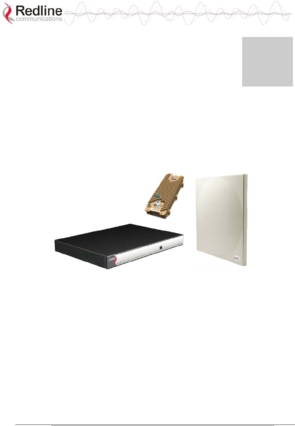
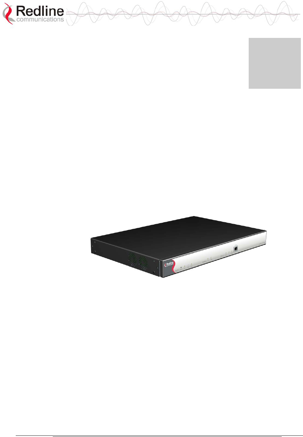
The system consists of an indoor terminal and an outdoor radio (transceiver and
antenna).
Figure 1: AN-50e System: Terminal, Transceiver, and Antenna
A point-to-point (PTP) link is comprised of a master system and a remote-end
system. The master system is connected to customer Ethernet network. The master
system establishes a bi-directional data link with an AN-50e remote-end system.
The remote-end system is connected to the remote-end customer Ethernet network
and receives and sends data under the control of the master system.
The AN-50e can also be deployed in a point-to-multipoint (PMP) configuration,
with the master-end system functioning as a central hub communicating to a
number of remote-end (subscriber) stations.

AN-50e
user manual
70-00033-02 Proprietary Redline Communications © 2004 November 2004
Page 14 of 96
2.1 How To Use This Manual
This user manual provides a guide to operating your system, including a product
overview, and step-by-step installation procedures.
To help insure a successful installation, please follow these principal steps in the
order presented:
The following principal steps should be performed in order:
1. Review the safety and service information (Section 1)
2. Unpack the System (Section 5.1)
3. Install and configure the AN-50e terminal (Section 5.4)
4. Install the outdoor radio (transceiver plus antenna) (Section 5.6)
5. Align the antenna (Section 5.7)
This User Manual also includes additional operational and background information
including:
- System Specifications (section 8.1: System Specifications on page 79)
- CLI Commands
- Glossary
AN-50e
user manual
70-00033-02 Proprietary Redline Communications © 2004 November 2004
Page 15 of 96
2.2 Terms Used in this Manual
The following terms are used in this manual:
Table 1: Terms
Term Description
AN-50e
terminal
(IDU)
Indoor unit
AN-50e
System
AN-50e
Radio
(ODU)
Transceiver + Antenna
Master System
Master Mode
The terminal configured as central equipment. This system
controls the wireless link polling and transmission
opportunities. The master system is connected to customer
Ethernet network and establishes a bi-directional data link
over-the-air with one or more remote-end AN-50e systems.
Remote-end System
Master Mode
The terminal configured as remote-end location equipment.
The remote-end system is connected to the customer
Ethernet network and receives and sends data over-the-air
under control of the master system.
AN-50e
user manual
70-00033-02 Proprietary Redline Communications © 2004 November 2004
Page 16 of 96
Chapter
3
3
3
S
Sy
ys
st
te
em
m
O
Ov
ve
er
rv
vi
ie
ew
w
The AN-50e is a high-performance, high-speed wireless Ethernet bridge terminal
providing a scalable multi-service platform from a common equipment
infrastructure and management system.
The system operates in the 5.4 GHz to 5.8 GHz band and includes advanced
technologies to address inter-cell interference. The system also delivers enhanced
security through a proprietary, over-the-air encryption scheme.
The AN-50e can be equipped with a narrow beam antenna to provide high
directivity for long-range operations over 80 km in clear line of sight (LOS)
conditions.
Figure 2: AN-50e terminal
The AN-50e system is a Class A digital device for use in a commercial, industrial
or business environment.
The system is equipped with dynamic frequency selection (DFS) to detect
interference from other devices using the same frequency and automatically take a
pre-selected action, such as disable transmission or relocate transmission to
alternative frequency. The system also includes an automatic transmitter power
control (ATPC) function to automatically adjust the Tx level of remote-end
systems to match a selected RSSI value.
The AN-50e system utilizes Redline’s advanced Medium Access Control (MAC)
design to provide efficient transmission of data in both PTP and PMP modes. In
PMP mode, the MAC incorporates a proprietary polling algorithm to support up to
250 individual subscriber stations from a single master end operating in a single
sector. Note that multiple masters can be installed on a single rooftop or tower to
provide multi-sector coverage.

AN-50e
user manual
70-00033-02 Proprietary Redline Communications © 2004 November 2004
Page 17 of 96
A single sector AN-50e PMP implements a distributed wireless L2 switch, with
one uplink port located on the sector controller (master) distributing bandwidth to
a variable number of subscriber stations (slaves).
- Each subscriber station (remote-end) is considered a separate wireless link.
- Each configured wireless link adds to the switch one remote-end port that is the
Ethernet port on the corresponding subscriber station.
- Each link (remote-end) is assigned one ID that is used to manage both the
connection traffic and the wireless link.
- The switch supports one broadcast/multicast group called default group, which
is automatically assigned a fixed ID.
The master-end MAC utilizes a request/grant polling mechanism to determine
which subscriber station requires bandwidth. This is achieved by periodically
polling each subscriber station to determine if there is a request for bandwidth. If
the subscriber station requests bandwidth then the MAC allocates the appropriate
number of time slots, in both the downstream and upstream direction, in
accordance with the CIR rate limits specified for that particular subscriber station.
The AN-50e PMP system supports 18 programmable CIR levels. Through an
external calculator the minimum Committed Information rate CIR rates allowed
for each subscriber station can be determined. Note that a minimum CIR of 8 Kbps
implies almost no CIR, and is referred to as Best Effort (BE) service.
With multiple subscriber stations compete for bandwidth, the MAC ensures that
time slots are allocated in a balanced manner, according to the different CIR
levels, during periods of over-subscription. For example, during peak times, the
MAC will first deny time slot allocations for everything above the provisioned
CIR, and then reduce bandwidth in a proportional manner to the remaining units
with varying CIR levels and priorities. With the support of CIR, the service
provider can offer different grades of service to each end user in a controlled
manner based on their service level agreements or contracts.

AN-50e
user manual
70-00033-02 Proprietary Redline Communications © 2004 November 2004
Page 18 of 96

AN-50e
user manual
70-00033-02 Proprietary Redline Communications © 2004 November 2004
Page 19 of 96
Chapter
4
4
4
P
Ph
hy
ys
si
ic
ca
al
l
D
De
es
sc
cr
ri
ip
pt
ti
io
on
n
4.1 AN-50e Terminal
The front panel of the terminal includes a LAN interface and three groups of LED
indicators: system, Wireless, and Ethernet. The rear of the terminal includes the
power connections, an F-Type female connector for the IF cable, and a BNC
connector for the time signal (future release).
4.1.1 Mounting
The terminal can be freestanding on a flat surface, or mounted into a standard 19-
inch or 24-inch equipment rack.
4.1.2 Power Supply
Power supply options include AC or DC supplies. Refer to the appendix for DC
terminal connections.
4.1.3 Wireless Section
This section describes the wireless cable connections and LEDs on the terminal.
IF Port (Radio Control)
The terminal has a female F-type port for communications with the radio. This
port is connected with a radio through a coaxial cable. Through this port and cable,
the terminal:
- Supplies power to the radio
- Transmits control information to the radio
- Receives status information from the radio
- Exchanges data traffic with other communicating Systems
AN-50e
user manual
70-00033-02 Proprietary Redline Communications © 2004 November 2004
Page 20 of 96
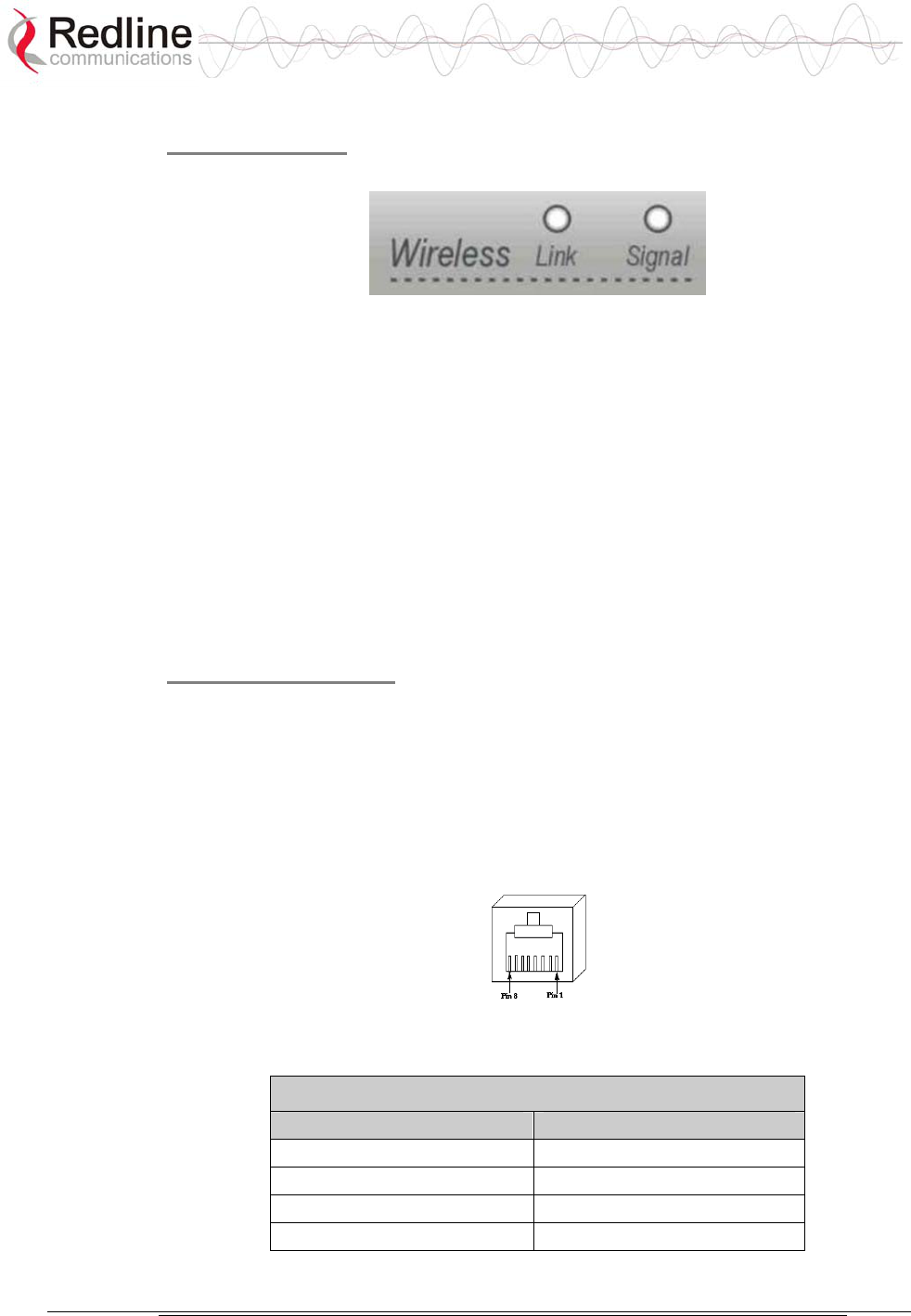
Wireless LEDs
The Wireless portion of the front panel includes Link and Signal indicator LEDs.
Figure 3: Front Panel - Wireless LEDs
Link LED
The Link LED lights solid green when the radio link to the remote-end terminal is
established. The LED will turn off if the link is lost.
Signal LED
The Signal LED lights solid green if the system is operating at the configured
Uncoded Burst Rate.
4.1.4 Ethernet Section
This section describes the terminal Ethernet LEDs and port connections.
Ethernet Data Port
The Ethernet Data port is always enabled. The port can be set for auto-sense or to
operate specifically in full duplex or half duplex mode and at 10 Mbps or 100
Mbps. Use a straight-through Ethernet cable for connecting to the PC/Server, or a
crossover cable for connecting to a switch or router.
The broadband Ethernet access is limited for data traffic and remote-end in-band
management. Product option keys are available to activate different rates of
Ethernet access. Refer to section 6.4.1: Options Key Screen on page 61.
Figure 4: RJ-45 Jack Face
Table 2: terminal LAN Ethernet Port Pinout
Jack Pin Function
1 Rx +
2 Rx -
3 Tx +
6 Tx -
Warning: Connecting a telephone cable to the Ethernet interface will cause
damage to the terminal.
AN-50e
user manual
70-00033-02 Proprietary Redline Communications © 2004 November 2004
Page 21 of 96
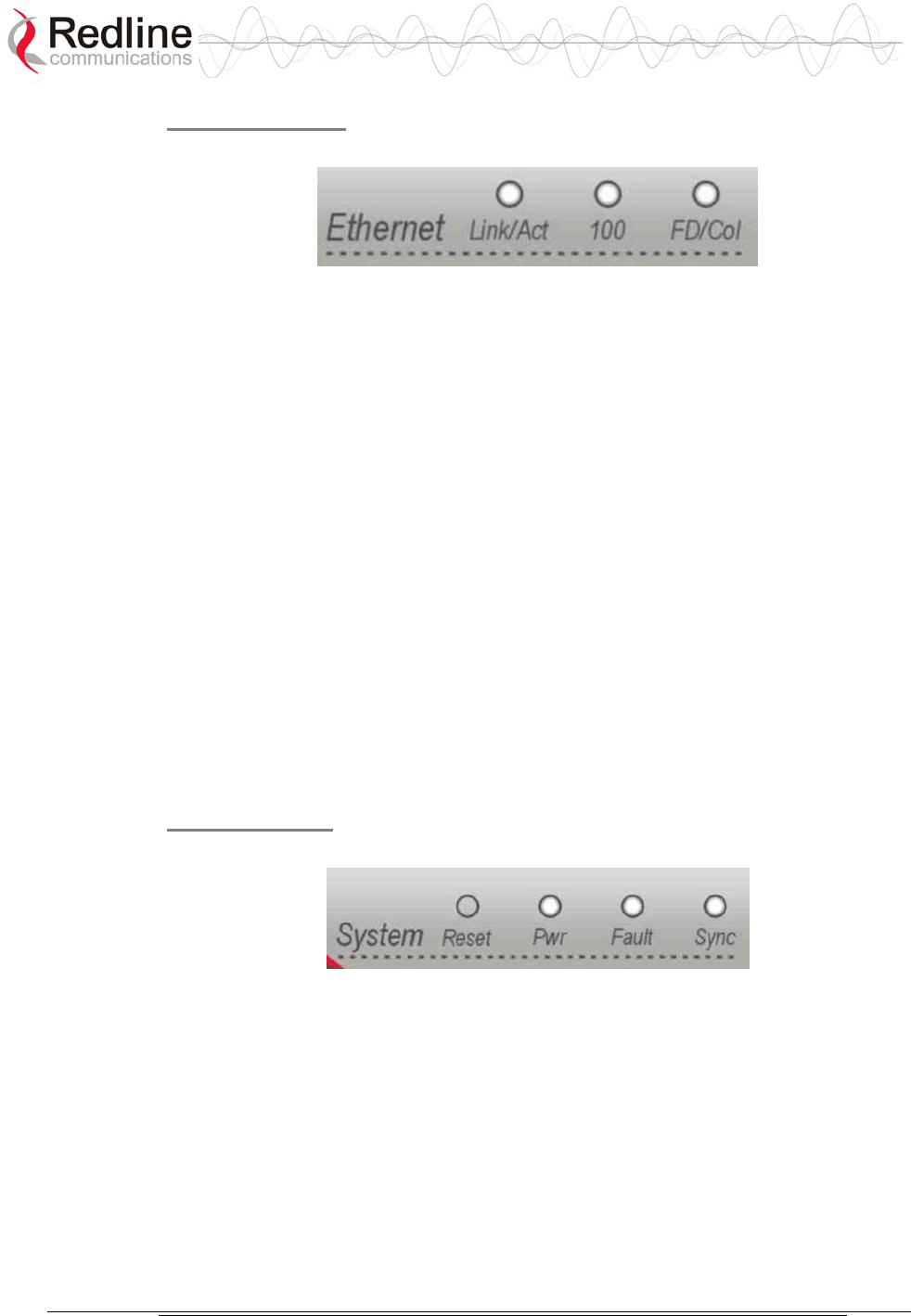
Ethernet LEDs
The Ethernet portion of the front panel display has three LEDs as shown below.
Figure 5: Front Panel: Ethernet LEDs
Link/Act LED
The Link/Act LED lights solid green when the Local Area Network (LAN)
connection is established, and there is no traffic. The Link LED will flash when
the Local Area Network (LAN) connection is established, and there is traffic.
100 LED
The 100 lights solid green when the Ethernet port is operating at 100 Mb/s. The
LED will not illuminate if the port is operating in 10 Mb/s mode. The Ethernet
port automatically selects the speed through auto-negotiation with either the host
computer/server or router/switch.
FD/Col LED
The FD/Col LED lights solid green when the LAN connection is operating in Full
Duplex mode and flashes when collisions are detected on the Ethernet port.
4.1.5 System Section
This section describes other general features of the front panel.
System LEDs
The system LEDs indicate power supply and system faults.
Figure 6: Front Panel: Reset Switch and System LEDs
Pwr LED
The Pwr LED lights solid green when the AC or DC power is properly applied to
the terminal. The Pwr light will not illuminate if there is an internal power supply
failure, the power cables are disconnected, or the fuse is blown.
Fault LED
The Fault LED lights solid red when a serious fault is detected within the system.

AN-50e
user manual
70-00033-02 Proprietary Redline Communications © 2004 November 2004
Page 22 of 96
Sync LED
The Sync LED lights solid green when the terminal clock is synchronized with the
external GPS clock (future release).
AN-50e
user manual
70-00033-02 Proprietary Redline Communications © 2004 November 2004
Page 23 of 96
Reset Switch
The reset button is recessed in the front panel of the terminal. To operate the
switch, use a small narrow object (i.e., paper clip) to depress the switch.
Table 3: Front Panel Reset Switch
Operation Result
Depress
switch less
than 5
seconds.
A short reset is equivalent to cycling the terminal power
off/on. Statistical values are reset. The current version of
software is retained.
A short reset may also be activated remotely from the
Web maintenance tool by clicking on the System Reset
button at the bottom of the System Configuration screen.
Depress
switch
longer
than 5
seconds.
A long reset reloads the factory default configuration
settings.
The long reset effects the following settings:
IP address = 192.168.25.2
netmask = 255.255.255.0
RF channel = 5765 MHz
Radio Enable = disabled
Login = admin
Password = admin
.
4.1.6 Time Synchronization Port
The AN-50e has one BNC input on the rear panel for time synchronization. This
port accepts a standard IRIG-B signal (1 pps pulse) from a GPS satellite clock.
This port is currently disabled, and will be enabled in a future release.
4.1.7 Grounding Connection
A ground lug connection terminal is located on the back of the AN-50e system.
Correct grounding is very important for safe operation of wireless equipment.
Refer to the installation section for additional information.
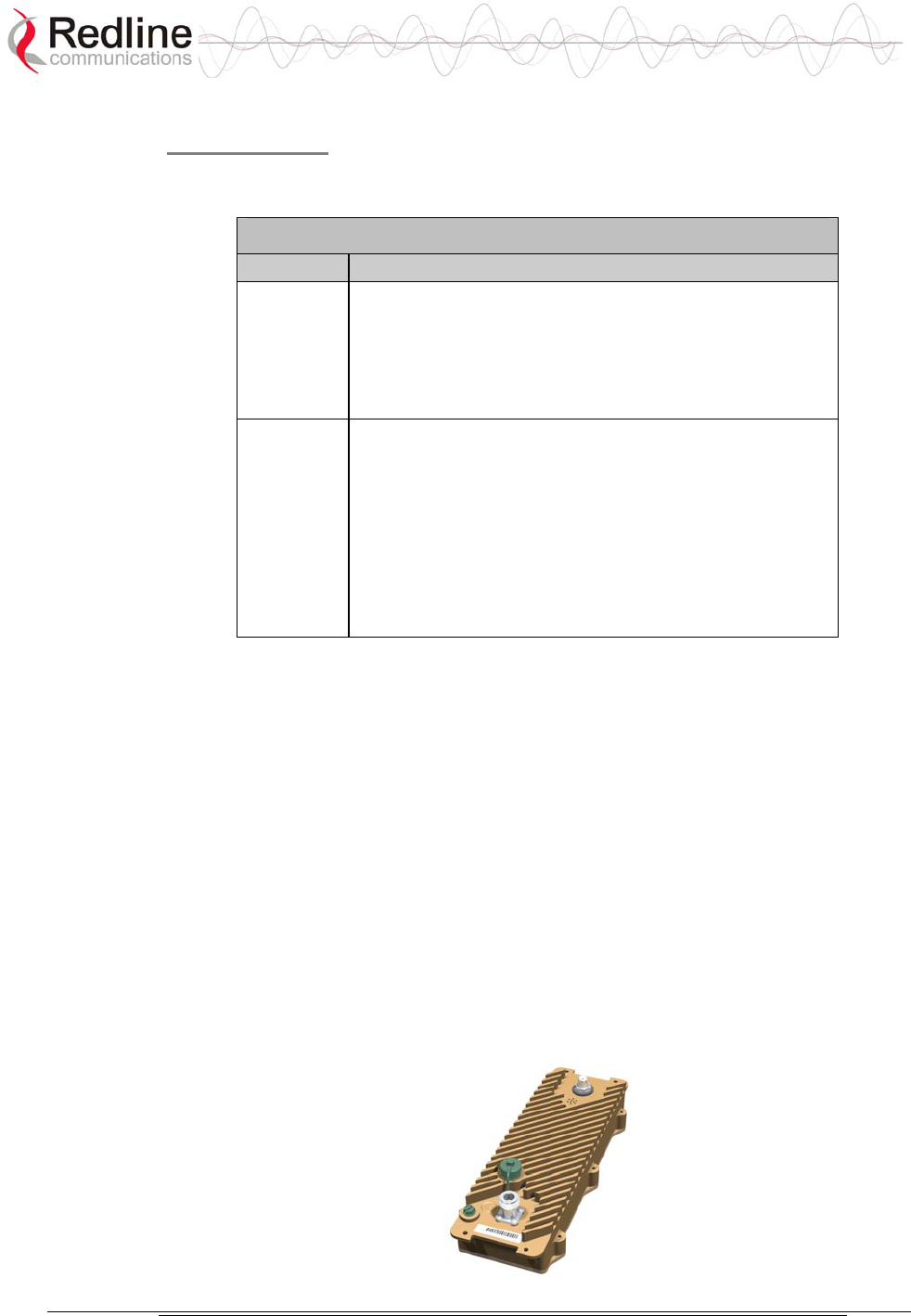
4.2 Transceiver
The radio transceiver is housed in an aluminum alloy housing. The connectors are
listed in the following sections.
AN-50e
user manual
70-00033-02 Proprietary Redline Communications © 2004 November 2004
Page 24 of 96
Figure 7: Transceiver
IF Port (Radio Control)
The transceiver IF port (female F-type connector) is for communications with the
terminal. This port is connected with the terminal through coaxial cable.
RF Connector
The transceiver RF port (female N-type connector) is for sending/receiving the RF
signal to/from the antenna. A short coaxial cable is provided to connect the
transceiver to the antenna.
Alignment Pin and Audible Signal
To assist in aiming the antenna, an external alignment pin is provided on the
transceiver. This pin provides a small voltage output (0-5 VDC) that varies relative
to the received signal strength. The transceiver also has an internal buzzer to
provide an audible indication of the received signal strength. Use the Web
interface field General Antenna Alignment to enable and disable this feature
(Refer to section 6.3.1: Configure System on page 49).
4.3 Antenna
The antenna units for master system and the remote-end systems are different.
Descriptions and specifications for available antennas are provided in section 8.3:
Antenna and Power Specifications on page 82.
Figure 8: One-Foot Flat Antenna
RF Connector
The transceiver RF port (female N-type connector) is for sending/receiving the RF
signal to/from the transceiver. A short coaxial cable is provided to connect the
antenna to the transceiver.

AN-50e
user manual
70-00033-02 Proprietary Redline Communications © 2004 November 2004
Page 25 of 96
4.4 Mounting Bracket
A mounting bracket is provided with the system. The vertical mount bracket can
accommodate 1 ¾" to 4 ½" (4.45 cm to 11.45 cm) OD masts for many commercial
tower installations.

AN-50e
user manual
70-00033-02 Proprietary Redline Communications © 2004 November 2004
Page 26 of 96

AN-50e
user manual
70-00033-02 Proprietary Redline Communications © 2004 November 2004
Page 27 of 96
Chapter
5
5
5
S
Sy
ys
st
te
em
m
I
In
ns
st
ta
al
ll
la
at
ti
io
on
n
This section of the manual presents a basic overview of the steps required to install
the terminal, outdoor transceiver, antenna, and associated equipment.
Important: This system must be installed by a professional installer who is
familiar with both data network issues and RF installations including grounding
and lightning protection.
5.1 Unpacking the AN-50e
The system comes packaged with the following items:
- User Manual
- Terminal
- Radio:
- T-54, T-58, or T-58 Transceiver
- Antenna
- Antenna Mounting Bracket
- Cabling
- RF Cable
- IF Cable
- AC/DC Power Cables (AC option only)
- DC Power Cable (DC option only)
- Miscellaneous:
- 19" mounting brackets (terminal)
A complete list of items included in the system is available on the packing list
included with the system.
AN-50e
user manual
70-00033-02 Proprietary Redline Communications © 2004 November 2004
Page 28 of 96
5.2 Site Planning
IMPORTANT: Review the safety tips provided in section 1: Important Safety &
Service Notices on page 7 of this manual before installing the system.
Installation steps for the system are not complicated, but do involve some
construction and electrical work. This system must be installed by a professional
installer who is familiar with both data network issues and RF installations
including grounding and lightning protection.
The following tables summarize the requirements for installing the terminal and
radio equipment.
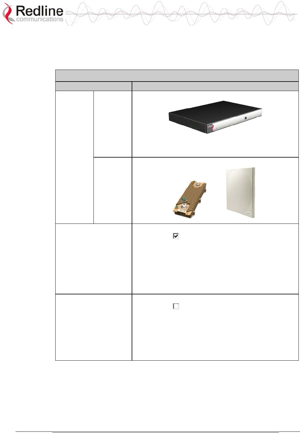
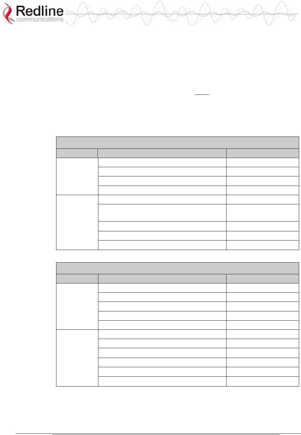
Table 4: Terminal (Inside) Installation Checklist
Item Description Notes
Terminal
Supplied 19" rack mounting tabs
with Power cables (AC and/or DC options)
system IF port coaxial cable
Terminal mounting equipment (rack or tray)
Customer
supplied
Power: AC power source
DC power source
Items Ethernet port cabling
Building ground connection
Grounding wire
Table 5: AN-50e Radio (Outside) Installation Checklist
Item Description Notes
Mounting bracket
Supplied T-54, T-58, or T-58 transceiver
with Antenna
system IF port cable
RF port cable
Antenna aiming directions (site path survey)
IF port cable (supplied)
Customer Antenna mast
supplied Building ground connection
Items Grounding wire
Waterproofing material for connections
AN-50e
user manual
70-00033-02 Proprietary Redline Communications © 2004 November 2004
Page 29 of 96
5.2.1 Master System Settings
The following table lists the master system parameters must be set prior to
operation of the wireless portion of the system.
Refer to section 6.3: System Configuration Screens on page 49 for additional
details of these fields.
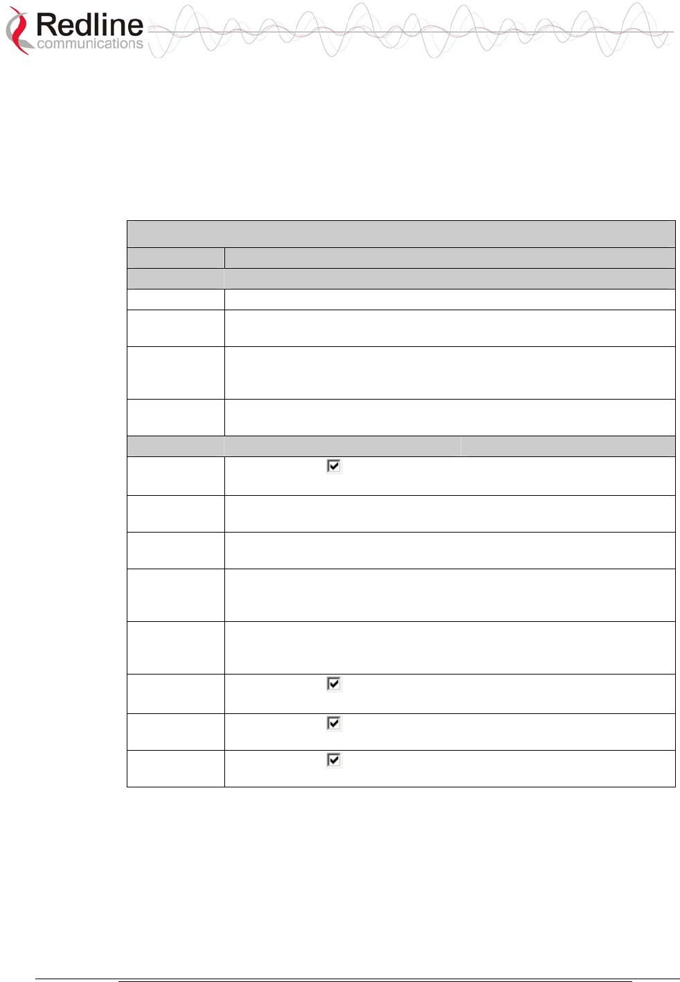
Table 6: Required Configuration Settings - Master System
Item Description
Ethernet
IP address Network address of the AN-50e master system (must be unique).
IP Subnet
Mask
Network subnet mask.
Default
Gateway
Address
Default router/gateway on the local Ethernet segment.
Ethernet
Mode
Select the operating mode of the Ethernet port (auto-negotiate, 10/100
Mbps).
Wireless
Master
Mode
Check this box to enable the System to operate as the master
system. Only one terminal must be designated master.
RF Freq.
[MHz]
Enter the channel center frequency of the system.
TX Power
[dBm]
Enter the default transmit power level (dBm). Refer to section 8.3:
Antenna and Power Specifications on page 82.
DFS Action Select the mode of operation for DFS on this terminal. If the DFS
function is required by local regulations, then DFS will be set on and
this selection will be disabled.
DFS
Antenna
Gain
Enter the antenna gain (dBm). This value must be set to match the
system antenna.
ATPC
Enable
Check this box to enable the Automatic Transmit Power Control
function.
Adaptive
Modulation
Check this box to enable adaptive modulation mode.
Radio
Enable
Check this box to enable the radio transmitter.
AN-50e
user manual
70-00033-02 Proprietary Redline Communications © 2004 November 2004
Page 30 of 96
5.2.2 Remote-end System Settings
The following remote-end system parameters must be set prior to operation of the
wireless portion of the system. Refer to section 6.3: System Configuration Screens
on page 49 for additional details of these fields.
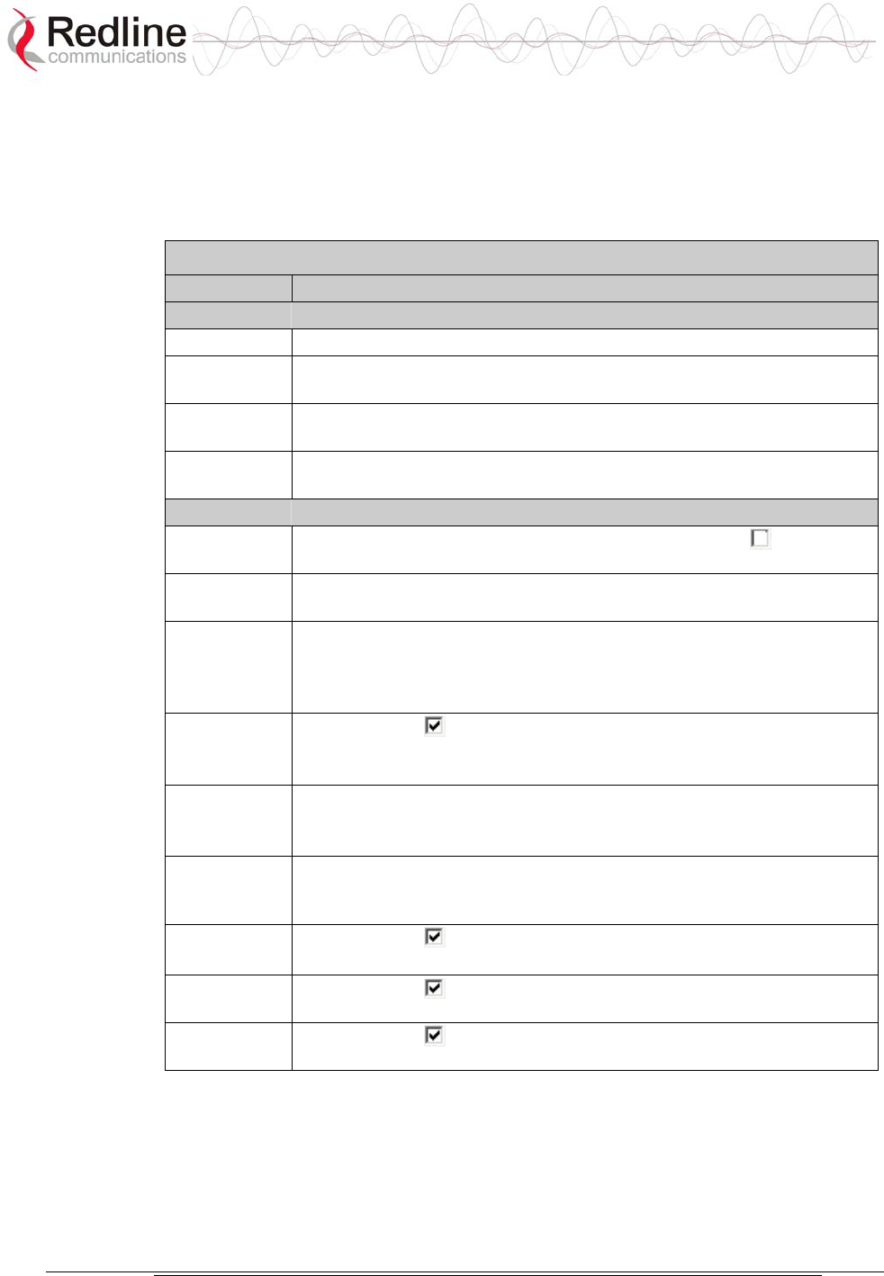
Table 7: Required Configuration Settings - Remote-end system
Item Description
Ethernet
IP address Network address of the AN-50e remote-end system (must be unique).
IP Subnet
Mask
Network subnet mask.
Default
Gateway
Default router/gateway on the local Ethernet segment.
Ethernet
Mode
Select the operating mode of the Ethernet port (auto-negotiate, 10/100
Mbps).
Wireless
Master
Mode
Ensure that the Master Mode check box is not checked ( ).
RF Freq.
[MHz]
Enter the channel center frequency of the system.
TX Power
[dBm]
Enter the default transmit power level (dBm). Refer to section 8.3:
Antenna and Power Specifications on page 82.
If the TX power levels are restricted by local regulations, the maximum
Tx power available will be limited to this value.
Auto Scan Check this box to enable the remote-end System to automatically
scan for the frequency of the AN-50e Master (system with Master
Mode setting enabled).
DFS Action Select the mode of operation for dynamic frequency selection (DFS).
If the DFS function is required by local regulations, then DFS will be
set on and this selection will be disabled.
DFS
Antenna
Gain
Enter the antenna gain (dBm). This value must be set to match the
System antenna.
ATPC
Enable
Check this box to enable the Automatic Transmit Power Control
function.
Adaptive
Modulation
Check this box to enable adaptive modulation mode.
Radio
Enable
Check this box to enable the radio transmitter.
AN-50e
user manual
70-00033-02 Proprietary Redline Communications © 2004 November 2004
Page 31 of 96
5.3 General Site Survey
5.3.1 Site Path Survey
The RF signal path profile is required to determine the location, height, and aiming
requirements for installation of the wireless system radio/antenna.
Site Path Profile
The completed path profile should include the following information:
Table 8: Site Path Profile
Antenna Description
Location Instructions to identify the location for installing the antenna mast.
May include blueprints and specify material list.
Height
Mounting height for antenna.
Azimuth Horizontal aiming direction for the antenna (magnetic or GPS
compass)
Elevation angle
Vertical aiming for antenna (spirit level).
Expected RSSI Use the Link Budget tool to determine the expected receive signal
strength (RSSI).
A critical parameter to consider is the range at which communicating wireless
systems are required to operate. Range performance is determined by empirical
formulas that consider a number of equipment and environmental factors.
The Link Budget Tool will calculate expected performance of the link for a
specified range. Ensure that the installation sites will meet performance
requirements before moving to the next step.
Identify Best Path
The next step is to conduct a general site survey to determine the location for the
antenna. This involves a survey to identify building and structures that can be used
to mount an antenna. Refer to the specification for the maximum IF cable length.
For maximum performance in OLOS deployment, it is recommended to mount the
antenna in a location where there is direct line of sight to the receiving wireless
system. If the obstruction in the path is not exceptionally high, it may be possible
to aim both antennas near the top of the obstruction. The antenna should be
positioned to provide maximum clearance within the first Fresnel zone of the
direct path (as high as possible, on either a tall building or tower).
The wireless system also supports installation in non-line-of-sight (NLOS)
conditions. A satisfactory multipath RF signal can often be obtained by directing
each antenna towards a structure in sight of both communicating wireless systems.
AN-50e
user manual
70-00033-02 Proprietary Redline Communications © 2004 November 2004
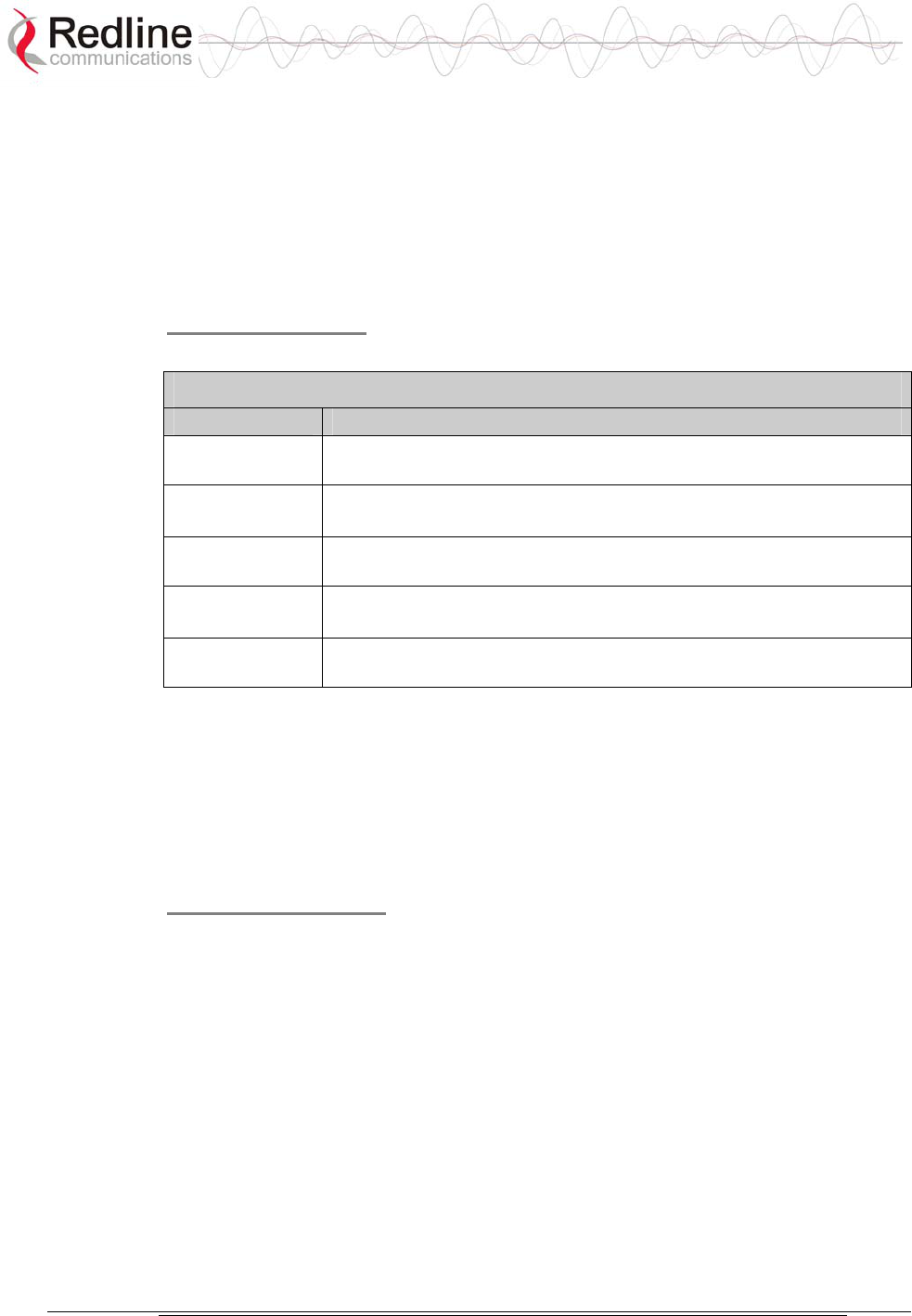
Page 32 of 96
Figure 9: Antenna Mounting Locations
The recommended method for obtaining a satisfactory RF signal is to test a
number of antenna positions and measure the signal-to-noise ratio and received
signal strength (RSSI) for each position. Antenna aiming instructions are provided
in section 5.7: Antenna Alignment on page 40.
Channel Selection -- Identify RF Interference
It is also important to test for RF interference at the intended rooftop or tower
installation site. RF interference can be caused by any wireless system in the area
that is operating in the same frequency band as the wireless. Accurate analysis
requires the use of specialized RF test equipment. The primary purpose of these
tests is to determine what channels are available for use on the wireless system.
Antenna Mounting Equipment
When the antenna location has been established, plans should be made for
installation of the antenna mast or alternative mounting equipment.
IF Cable Routing
Plans should be made for routing the IF cable from the radio/antenna to the
terminal. In some locations it may also be possible to install the IF cable on the
outside of the building. If the building must be penetrated to run the IF cable, it is
important to verify that building blueprints and/or drawings are up to date and
accurate, and that all permissions are obtained for the required modifications.

AN-50e
user manual
70-00033-02 Proprietary Redline Communications © 2004 November 2004
Page 33 of 96
5.4 Install the AN-50e Terminal
The following are general guidelines for mounting and connecting the terminal.
5.4.1 Mounting
The wireless terminal may be rack or shelf mounted. If rack mounted, each
terminal will occupy one rack unit (RU) in a standard 19-inch rack. Do not block
the ventilation screens on the terminal.
5.4.2 Grounding
A grounding screw is provided on the rear of the terminal. The terminal must be
properly grounded in compliance with local and national codes.
Connect a grounding cable from the grounding screw on the rear of the terminal to
the rack grounding or the building ground. The terminal must be adequately
grounded for safe operation. Do not rely on the removable power or signal cables
to provide system grounding.
5.4.3 IF Cable
The IF cable supplies power to the radio. It is necessary to attach the IF cable
before aiming the antenna.
Important: The wireless parameters should be set before the IF cable is connected
to the terminal. This will avoid interference with other wireless devices located in
the area.

AN-50e
user manual
70-00033-02 Proprietary Redline Communications © 2004 November 2004
Page 34 of 96
Check the following items before routing the IF cable from the terminal to the
radio location:
- Look for a building plan for any existing cable routing.
- Check drilling requirements, through a wall or ceiling for routing the cable.
- Avoid excessive force or stress on the connectors as the cable may get
damaged. Do not use connectors as cable grips to pull cable through raceway or
conduit.
5.4.4 Power
An AC power cable is supplied with the system. This product is supplied with a
grounding power plug. Do not defeat this important safety feature.
The terminal may be equipped with single or dual AC or DC power supplies, or a
combination of AC and DC power supplies.
Each AC power supply includes an AC connection cable. A grounded AC outlet
must be provided within about one meter of the terminal mounting location. This
cable is supplied with a grounding power plug. Do not defeat this important safety
feature.
Each DC power supply includes a DC connection cable. A terminal block with the
DC connections must be provided within about one meter of the terminal
mounting location. There is no on/off switch for DC power supply. Refer to
Section 8.2: DC Power Supply Cable Connections for a description of these
connections.
5.4.5 Ethernet
Ethernet connections are described in the following sections.
5.4.6 Starting Up the terminal
Connect the DC or AC power to the terminal and turn on using the toggle switch
(AC model only, DC models are not equipped with a toggle switch) at the rear of
the terminal. The system Pwr LED should illuminate green to indicate power to
the terminal. If the Pwr LED is not on or the Fault LED lights red, there is a
problem with the terminal.
Important: Power-off the terminal before connecting or disconnecting any cables.
5.5 Configure Essential System Parameters
All system management functions can be performed using the HTML-based
graphical user interface. This method allows the operator to use a common Web
browser to access and control the terminal. Microsoft Internet Explorer is
recommended for its support of context-sensitive help.
This procedure is applicable for the first-time setup of a new terminal, or if the
factory default parameters have been restored using the front panel reset or
through the network controls.

AN-50e
user manual
70-00033-02 Proprietary Redline Communications © 2004 November 2004
Page 35 of 96
5.5.1 Setup PC Address
Connecting the Test Computer
The terminal may be connected directly to the host computer using a straight-
through CAT 5/UTP cable.
Figure 10: terminal Connected To Host Computer
For correct operation the host computer and the terminal must appear to be on the
same subnet. Set the IP address of the PC to 192.168.25.10 and the subnet mask to
255.255.255.0.
Power-on the terminal. Restore the factory default settings by depressing the reset
switch on the front panel for more than five seconds. Launch the Web browser and
enter http://192.168.25.2 in the address field.
Figure 11: System Address in Browser Address Bar
The login screen will be displayed. Login by entering 'admin' for the User Name
and Password.
Figure 12: User Name And Password Dialog

AN-50e
user manual
70-00033-02 Proprietary Redline Communications © 2004 November 2004
Page 36 of 96
The following sections list parameters that must be set before the terminal is
connected to the Ethernet port, or the IF cable is connected to the transceiver.
5.5.2 Ethernet Settings
The network address settings for the every terminal must be configured before the
terminal can be connected to the local area network. Only the following Ethernet
settings need to be adjusted at this time:
IP address: Enter the IP address for this terminal. Each System must also have
a unique IP address.
IP Subnet Mask: Enter the IP subnet mask.
Default Gateway Address: Enter the IP address of the default router or
gateway on the local Ethernet segment.
Ethernet Mode: Select the operating mode of the Ethernet port (auto-
negotiate, 10Base-T, or 100Base-T).
5.5.3 Wireless Settings
The wireless parameters must be set properly before the terminal is enabled to
transmit -- otherwise it may cause interference to other high frequency devices
operating in the vicinity. See section 6.3.1: Configure System on page 49 for more
details.
Master System Settings (Master Mode )
The following settings should be set for the system operating as master:
Master Mode: Check this box to enable this system to operate as the master
system. Only one terminal must be designated Master.
RF Freq. [MHz]: Enter the channel center frequency of the system.
TX Power [dBm]: Enter the default tx power level (dBm). Refer to section 8.3:
Antenna and Power Specifications on page 82.
DFS Action: Select the mode of operation for DFS on this terminal.
Important: Where specified by local regulations, the DFS feature will always be
enabled. The default selection will be Chg Freq.
DFS Antenna Gain: Enter the antenna gain (dBm). This value must be set to
match the system antenna.
ATPC Enable: Check this box to enable the Automatic Transmit Power
Control function. This feature will automatically adjust the power level of the
remote-end system.
Adaptive Modulation: Check this box to enable adaptive modulation mode.
Radio Enable: Check this to enable the radio transmitter.

AN-50e
user manual
70-00033-02 Proprietary Redline Communications © 2004 November 2004
Page 37 of 96
Remote-end system Settings
Configuration is the same for the remote-end system, except for the following
settings:
Master Mode: Ensure that this setting is not checked ( ). Only one of the
systems must be operated in Master Mode.
Auto Scan: Check this box to enable the remote-end system to automatically
scan for the transmitting/receiving frequency channel of the Master-end system
(Master Mode setting enabled).
Save Settings
Save: Click the Save button to save the current parameter settings.
Depress the reset switch on the front panel for less than five (5) seconds (standard
reset) to make these changes active.
Important: Following the reset, you will need to enter the new IP address for the
terminal in the Web browser to access the Web screens. Also, the IP address and
IP Subnet Mask setting of the PC must be in the same subnet as the new IP
address. Otherwise, you will be unable to communicate with the terminal.
5.6 Install the Transceiver and Antenna
The next step is to assemble and mount the radio and antenna on a building
structure, pole or tower.
5.6.1 Assemble Mounting Bracket
The antenna and mounting brackets have been designed to withstand strong winds;
it is imperative that all hardware for the mounting brackets be securely fastened to
avoid any movement, which could introduce misalignment.
This mounting bracket can be used for any supplied flat panel antenna.
1. Using the long bolts to connect the major parts of the bracket.
2. Attach the antenna mounting plate using the four sets of screws and washers.
3. Complete the assembly of the mounting bracket, ensuring that you utilize all
washers and split washers supplied.
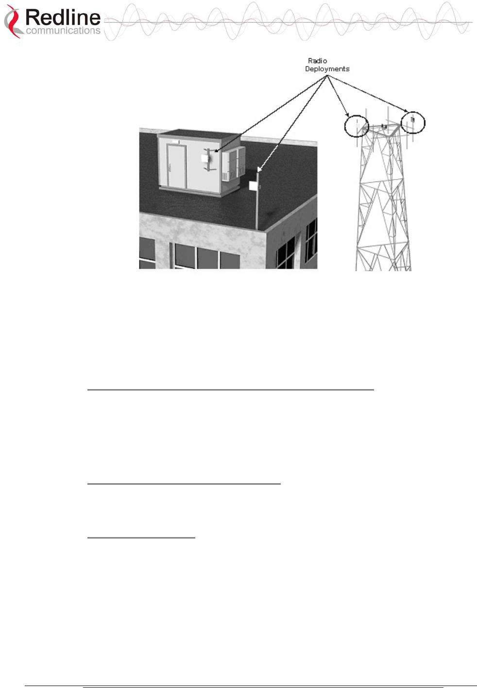
5.6.2 Mounting the Transceiver
The transceiver can now be mounted to the bottom of the bracket. The transceiver
is secured by two tabs located on the bottom of the bracket. Refer to the following
illustration.
AN-50e
user manual
70-00033-02 Proprietary Redline Communications © 2004 November 2004
Page 38 of 96
Figure 13: Example Mounting Bracket with Radio
Position the radio, with the connectors facing downwards, below the bracket. The
radio must endure high winds and extreme changes in weather. Ensure that all nuts
are correctly tightened.
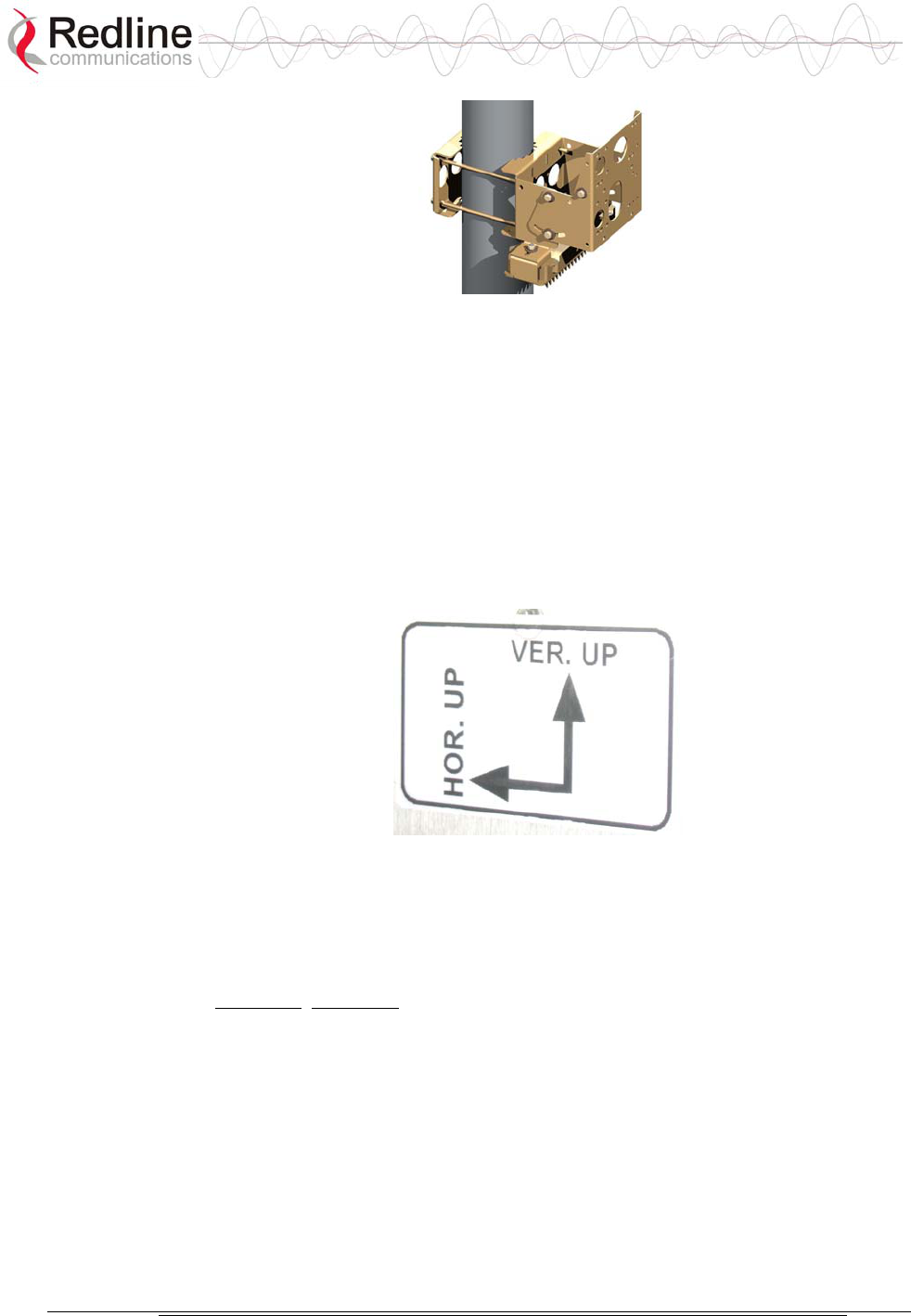
5.6.3 Mounting the Antenna
There is an arrow on the back of the antenna. The arrow must point in the same
direction for both the local and remote-end systems to ensure proper polarization
when the antenna is deployed (see Figure 14: Antenna Polarization). Ensure the
proper polarization is used for the antenna before attaching the mounting bracket.
Figure 14: Antenna Polarization
Attach the antenna to the bracket using the four bolts and washers.
5.6.4 Connecting the RF and IF Cables
It is extremely important to ensure that all connectors are correctly tightened.
Over tightening the mounting screws may damage the transceiver unit.
The following steps describe the cable installation process:
1. Connect the RF cable to the transceiver and the antenna. Ensure that the cable
droops downward from the transceiver to facilitate water runoff. The connector
should be tightened finger-tight and then tightened an additional 1/8 of a turn.
Properly weatherproof the connection.
2. Connect the IF cable to the transceiver. Ensure that the cable droops downward
from the transceiver to facilitate water runoff. The connector should be
tightened finger-tight and then tightened an additional 1/8 of a turn. Properly
weatherproof the connection.
AN-50e
user manual
70-00033-02 Proprietary Redline Communications © 2004 November 2004
Page 39 of 96
3. Ground the radio and antenna and the mounting bracket using the grounding
screws provided. All grounding connections should be made with wire that is
at least #2 AWG. Painted or dirty surfaces should be cleaned thoroughly down
to bare metal and connections should be well tightened. Follow all local and
national codes.
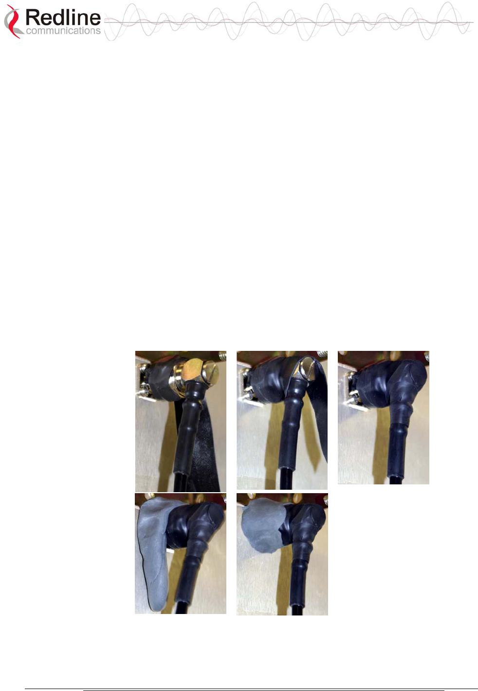
5.6.5 Weatherproofing Procedure
The professional installer may use their own weatherproofing preferences,
provided they do not use silicon-based materials or PVC tape.
Important: This method of weatherproofing must be completed on ALL external
connections. If lightning arrestors are used, all the associated connections and
arrestors must be completely wrapped in splicing tape.
1. Begin by wrapping with splicing tape. Try to start as close to the radio/antenna
as possible. Stretch and wind the tape back along the connector housing
making very sure there are no gaps in the tape. Continue to wrap the tape
tightly along the cable for at least 15 cm.
2. Use mastic putty and work this in well around the connector and the body of
the radio. Continue to work the putty to make a watertight seal.
1. The connection is now weatherproof.
Figure 15 Waterproofing Outdoors Connections

AN-50e
user manual
70-00033-02 Proprietary Redline Communications © 2004 November 2004
Page 40 of 96
5.7 Antenna Alignment
The antenna alignment can be performed after the antenna and transceiver are
mounted and connected to the terminal using the IF cable.
It is recommended to perform alignment first on one antenna, and then to repeat
the procedure at the remote-end end.
5.7.1 Basic Alignment
Basic antenna alignment can be performed using the alignment voltage pin built
into the transceiver. This transceiver alignment pin is always active. A higher
voltage indicates a stronger signal received from the remote-end transmitter.
The site survey should include the antenna aiming instructions. When using a
magnetic compass, the tower metal will affect the accuracy. Magnetic declination
(difference between true North and Magnetic North) must also be taken onto
account.
Swing the antenna elevation adjustment through the peaks and valleys to obtain
the maximum strength. Repeat this to obtain maximum strength for the azimuth
adjustments. Repeat these steps for the remote-end antenna. When the alignment is
complete, all loosened nuts should be tightened. Tightening all nuts evenly in
rotation may help avoid altering the antenna position.
If the link is non line-of-sight (NLOS), a suitable reflecting surface such as a
building or billboard must be used. The only certain way to determine if a NLOS
link will work is to install the link and then swivel the antennas until a usable
signal is received.
5.7.2 Verify Alignment Using RSSI
Once the basic alignment has been completed, the RSSI value should be checked
against the estimated value obtained from the link budget. If the link is LOS, the
value should not differ by more than about 5 dBm. If the RSSI is much less than
the budget prediction, the antenna may be aligned to an OLOS, or an NLOS path.
It is also possible that the antennas may be aligned to a sidelobe. Alignment on a
sidelobe of the received beam may be indicated by an unstable reading or a large
difference in RSSI values at each end. A thorough elevation and azimuth sweep
should then be repeated, while observing the RSSI values. The value should rise
when a sidelobe is aligned, then fall and rise higher when the antenna is aligned to
a direct signal path. Further movement of the antenna will cause the RSSI value to
decrease and rise to a lower peak as the antenna is aligned to another sidelobe.
This procedure should be repeated for both the elevation and azimuth at each end
of the link.
AN-50e
user manual
70-00033-02 Proprietary Redline Communications © 2004 November 2004
Page 41 of 96
Chapter
6
6
6
U
Us
si
in
ng
g
t
th
he
e
W
We
eb
b
I
In
nt
te
er
rf
fa
ac
ce
e
This section: describes the procedures for configuring and operating the terminal
via the web interface.
Communication with the terminal is achieved over the Ethernet port using
hypertext transfer protocol (HTTP). This offers the advantage of allowing the
operator to access and control the terminal remotely from any geographical
location having access to the Internet.
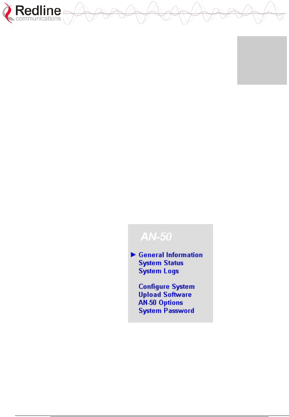
6.1 System Menu
When the user is successfully logged in, the General information page will be
displayed. On the left will be a menu of all available pages. The operator can point
and click on any of the blue text lines in the menu to display the selected page.
Figure 16: On-Screen Menu
The administrator (admin) has unrestricted access to all screens. All other users
have restricted access. See the following table for details.
AN-50e
user manual
70-00033-02 Proprietary Redline Communications © 2004 November 2004
Page 42 of 96
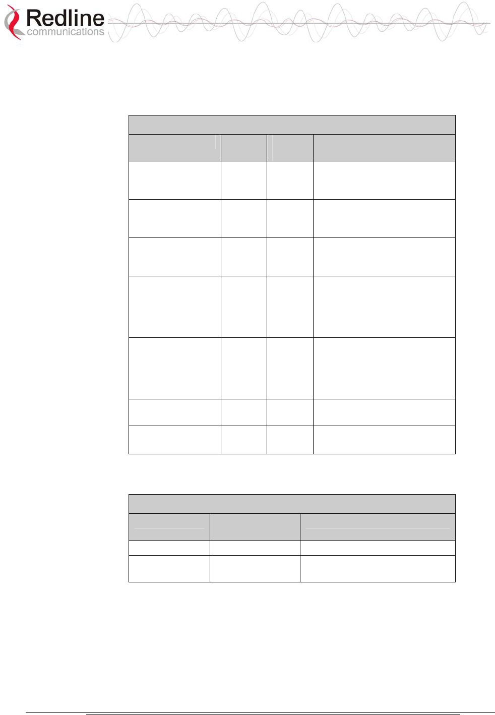
Table 9: Web Screens
Screen Admin
Access
User
Access
Description
General
Information
X X View general system
identification and
configuration settings.
System Status X X View system information,
Ethernet statistics, and
wireless statistics.
System Logs X X View the last forty system
activity and error messages
recorded by the terminal.
Configure System X View and adjust
configuration settings for
general system identification,
IP address, management
functions, and wireless.
Upload Software X Upgrade the existing
software load of the terminal
with new software stored in a
binary file on the server or
host computer.
AN-50e Options X Upgrade the terminal with
custom options.
System Password
X X Change your login password.
Table 10: Default System Users
Username Default
Password
Description
admin admin Access to all screens.
user user Access restricted to monitoring
screens.
AN-50e
user manual
70-00033-02 Proprietary Redline Communications © 2004 November 2004
Page 43 of 96
6.2 System Monitoring Screens
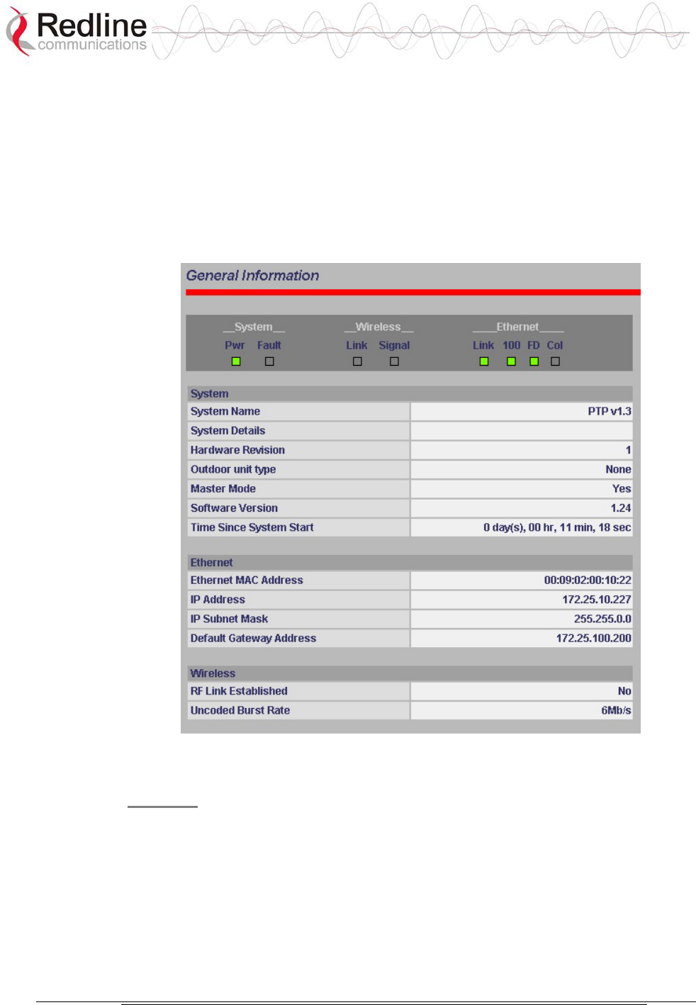
6.2.1 General Information
Click General Information to view general system information, Ethernet LAN
address information and wireless settings. This page includes a view of the
terminal front panel LEDs (refreshed every 30 sec.), plus a summary of general
information related to the configuration and status of the local terminal.
Figure 17: General Information Screen
System
The following is a brief description of each field on the General Information page:
System Name: Identifies the local terminal.
System Details: Specifies the location, telephone number and/or contact
information.
Hardware Revision: Indicates the hardware revision level for this terminal.
Outdoor Unit Type: Indicates the transceiver model number.

AN-50e
user manual
70-00033-02 Proprietary Redline Communications © 2004 November 2004
Page 44 of 96
Master Mode: Indicates if the system is operating as the master system.
Yes: Master system.
No: Remote-end system.
Software Version: Specifies the software version in use.
Time Since System Start: Specifies the time [dd/hh/mm/ss] since the system
started.
Ethernet:
Ethernet MAC Address: Hardware address of terminal.
IP Address: IP address of the terminal.
IP Subnet Mask: Subnet for the IP address.
Default Gateway Address: IP address of the default router/gateway on the local
Ethernet segment.
Wireless:
RF Link Established: Status for the wireless link connection.
Yes - RF link has been successfully established with the remote-end terminal.
No - RF link has not been established with the remote-end terminal.
Uncoded Burst Rate [Mb/s]: The actual current uncoded burst rate for the link.

AN-50e
user manual
70-00033-02 Proprietary Redline Communications © 2004 November 2004
Page 45 of 96
6.2.2 System Status
Click System Status in the menu to view system information and Ethernet statistics
and wireless statistics.
Figure 18: System Status Screen
General Information:
System Name: Identification for this terminal.
Software Version: Version of the running system software.
RF Link Established: Status of wireless link connection to remote-end system.
Yes- Link established to the remote-end system.
No - Link not established to the remote-end system.
Uncoded Burst Rate: Measured burst rate of wireless link.
Master Mode: Indicates the terminal configuration.
Yes - This is the master system.
No - This is a remote-end system.
Important: For each set of Systems, only one terminal must be designated Master.
RF Channel Frequency: Center frequency of the channel in use.
Tx Power: Transmit power level.
Cable Attenuation: Attenuation of the 800 MHz signal over the IF cable.

AN-50e
user manual
70-00033-02 Proprietary Redline Communications © 2004 November 2004
Page 46 of 96
Link Distance [Miles or Km]: Distance between systems.
RF Status [Error Code]: An error code indicating the condition of the system RF
components. See the RF Status Error Code Table 24: RF Status Error Codes on
page 74 for details. Code zero is normal.
Ethernet MAC Address: MAC address of this terminal.
IP address: IP address for the this terminal
IP Subnet Mask: IP subnet mask.
Default Gateway Address: IP address of the default router / gateway.
Ethernet LAN Statistics:
Rx packets: Number of non-errored packets received.
Rx packets - Discarded: Number of errored packets received.
Tx Packets: Number of Ethernet packets transmitted.
Wireless Statistics:
Received Signal Strength: Min: Minimum RSSI measured since the last screen
refresh.
Received Signal Strength: Mean: Average RSSI measured since the last screen
refresh.
Received Signal Strength: Max: Maximum RSSI measured since the last screen
refresh.
SINADR: Average signal to interference, noise and distortion ratio measured since
the last screen refresh. The ratio is based on the digital information provided from the
output of the A/D converter, and includes the effects of the AGC.
Rx Packets: Number of wireless packets received over the air from the remote-end
terminal.
Rx Packets: Retransmitted: Number of wireless packets retransmitted from the
remote-end terminal.
Rx Packets: Discarded: Number of wireless packets originating from the remote-end
terminal received over the air with errors due to degradation in the RF link.
Tx Packets: Number of wireless packets (including Ethernet frames and error
correction bytes) successfully transmitted over the air by the local terminal.
Tx Packets: Retransmitted: Number of wireless packets retransmitted over the air by
the local terminal. The retransmission scheme is based on the Automatic Repeat
Request (ARQ) algorithm that detects when packets are lost, and makes a request to
the MAC scheduler to repeat transmission of the lost packets.
Tx Packets: Discarded: Total number of transmitted wireless packets discarded by
the remote-end terminal, due to degradation in the RF link.

AN-50e
user manual
70-00033-02 Proprietary Redline Communications © 2004 November 2004
Page 47 of 96
Statistics Control Button:
Reset Statistics: Click this button to zero the counters for the Wireless and Ethernet
LAN Statistics displayed on this page.
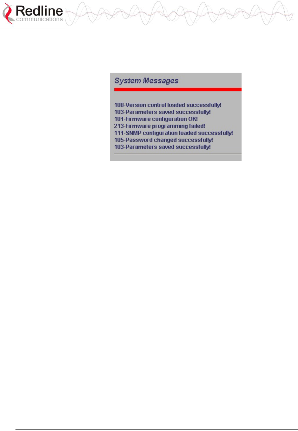
AN-50e
user manual
70-00033-02 Proprietary Redline Communications © 2004 November 2004
Page 48 of 96
6.2.3 System Logs Screen
Click System Logs in the menu to view the last forty system activity and error
messages recorded by the terminal.
Figure 19: System Logs Screen
The logs will also indicate if the following transactions were successfully
completed:
Save Configuration: Configuration screen.
Upload: Upload Software screen.
Change Password: System Password screen.
Send Options Key: AN-50e Options screen
Refer to section 7: Diagnostics and Troubleshooting on page 65 for a detailed
description of all event messages.
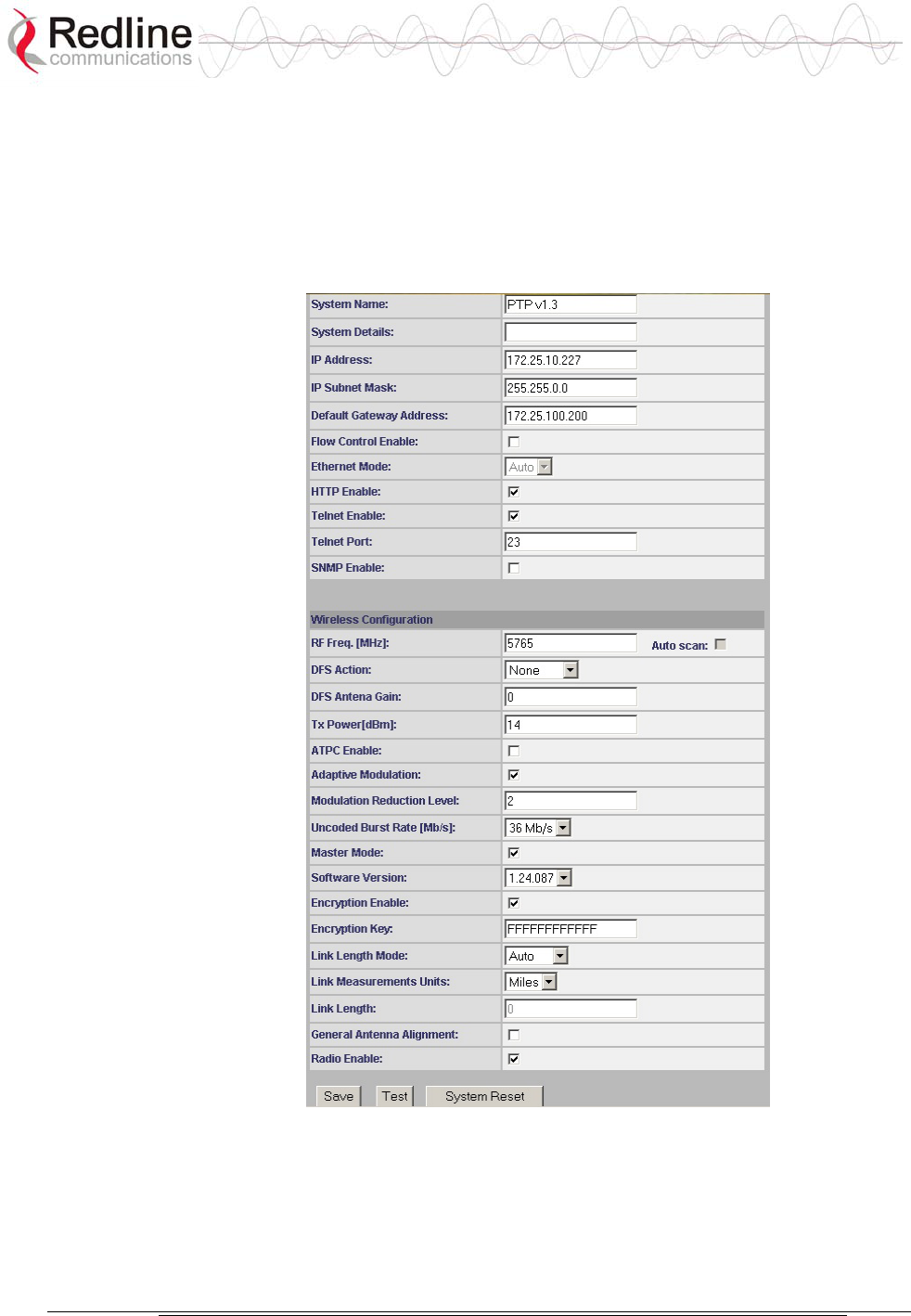
AN-50e
user manual
70-00033-02 Proprietary Redline Communications © 2004 November 2004
Page 49 of 96
6.3 System Configuration Screens
6.3.1 Configure System
Click Configure System in the menu to view and adjust configuration settings for
general system identification, Ethernet, and the wireless interface.
Figure 20: System Configuration Screen
Important: Ensure that all fields on the System Configuration Screen are filled out
properly for local and remote-end terminals. Errors in these fields will result in
the inability to establish a communication link. Please read carefully to ensure a
quick, trouble-free deployment.
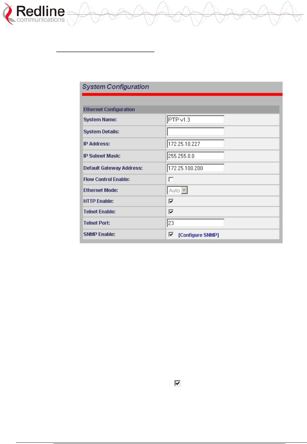
AN-50e
user manual
70-00033-02 Proprietary Redline Communications © 2004 November 2004
Page 50 of 96
Ethernet Configuration:
The IP address information must be set properly before the terminal is connected
to a public network -- otherwise address conflicts may occur with other devices on
the network.
Figure 21: System Configuration Screen - Ethernet Settings
System Name: Enter the name for this terminal. The name can be any
combination of up to 20 letters and numbers. The default name for the system from
the factory is set to WEB01.
System Details: Enter additional descriptive details about this terminal. The
description can be any combination of up to 20 letters and numbers.
IP address: Enter the IP address for this terminal. The factory default address is
192.168.25.2.
IP Subnet Mask: Enter the IP subnet mask. The factory default mask value is
255.255.255.0 (Class C subnet).
Default Gateway Address: Enter the IP address of the default router / gateway on
the local Ethernet segment.
Flow Control Enable: Check this box to enable flow control on the terminal.
The Flow control feature enables the terminal to request other Ethernet devices to
pause transmission during busy periods.

AN-50e
user manual
70-00033-02 Proprietary Redline Communications © 2004 November 2004
Page 51 of 96
Ethernet Mode: Select the operating mode of the Ethernet port.
Auto - Auto-negotiate the speed connection speed.
10 - Operate at 100Base-T only.
100 - Operate at 100Base-T only.
HD - Operate at half-duplex only.
FD - Operate in full-duplex only.
HTTP Server Enable: Check this box to enable configuration using the HTTP
(Web) interface.
Telnet Enable: Check this box to enable configuration using a Telnet session.
Refer to the CLI commands in section 8.4: CLI Interface on page 87.
Telnet Port: Enter the Telnet port address. The default Telnet port is 23. The port
can be changed to any other number between 23 and 65,000, excluding port 80.
SNMP Enable: Check this box to enable the Simple Network Management
Protocol (SNMP) agent. When this item is checked, clicking on the blue text
'Configure SNMP' beside the checkbox displays the SNMP Configuration screen.
See section 6.4.3: SNMP Settings on page 63 for additional information on setting
up SNMP for the AN-50e.
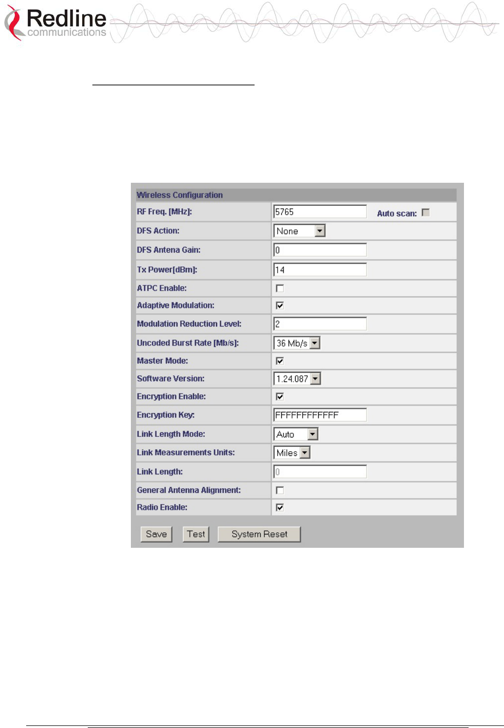
AN-50e
user manual
70-00033-02 Proprietary Redline Communications © 2004 November 2004
Page 52 of 96
Wireless Configuration:
The wireless parameters must be set properly before the terminal is allowed to
transmit using the radio -- otherwise it may cause interference to other high
frequency devices operating in the vicinity.
Refer to section 5.5: Configure Essential System Parameters on page 34 for
information about parameters that must be set before operating the wireless portion
of the system.
Figure 22: System Configuration Screen - Wireless Settings
RF Freq. [MHz]: Enter the channel center frequency of the system. The table
below specifies the center frequencies of each permitted channel. To avoid
interference, the channel frequencies of two links operating within close proximity
must be separated by 20 MHz or more.
Note: Availability of frequency bands listed in the following tables is based on the
factory entered option key.
Refer to the tables on the following page.
AN-50e
user manual
70-00033-02 Proprietary Redline Communications © 2004 November 2004
Page 53 of 96
The following table lists the 5.4 GHz channels available in CE regulated regions.
Table 11: CE: RF Channel Frequencies
T-54 Radio: 5.4 GHz
Center Frequency
(GHz)
Center Frequency
(GHz)
Center Frequency
(GHz)
5.500 5.580 5.660
5.520 6.500 5.680
5.540 5.620 5.700
5.560 5.640
The following table lists the 5.8 GHz channels available in the United Kingdom.
Table 12: UK: RF Channel Frequencies
T-58 Radio: 5.8 GHz T-58e Radio: 5.8 GHz
Center Frequency (GHz) Center Frequency (GHz)
5.735 5.735
5.755 5.755
5.775 5.775
5.835
The following table lists the 5.8 GHz channels available in North America.
Table 13: North America: RF Channel Frequencies
T-54 Radio: 5.4
GHz
T-58 Radio: 5.8
GHz
T-58e Radio: 5.8
GHz
5.480 to 5.715
(steps of 5 MHz)
5.735 to 5.815
(steps of 5 MHz)
5.735 to 5.840
(steps of 5 MHz)
DFS Action: Select the mode of operation for DFS.
The system set to master-mode monitors for interference from radar devices and
other equipment using the same channel frequency. When interference is detected,
the system automatically takes the action selected using the drop-down menu:
Important: DFS Action selection should be set to None where DFS function is not
required by regulations. DFS cannot be disabled where required by regional
regulations.
None: DFS is disabled.
Tx Off: Transmission is immediately disabled when radar signals are detected.
This action is recorded in the message log and an SNMP trap message is sent
(if SNMP enabled).
Following an interval of thirty minutes, the same channel is monitored for one
minute and if there are no DFS triggering events, the system resumes normal
operation. If DFS trigger conditions are still detected, operation is suspended

AN-50e
user manual
70-00033-02 Proprietary Redline Communications © 2004 November 2004
Page 54 of 96
for an additional thirty minutes. This cycle continues until no DFS trigger
events are detected or the operator manually reconfigures the system.
Chg Freq: Relocate transmission to alternative frequency immediately when
radar signals are detected. This action is recorded in the message log and a trap
message is sent (if SNMP enabled).
The new channel is selected based on allowable frequencies for the regulatory
region of that installation. The channel is monitored for one minute before the
system is allowed to transmit. If DFS triggering events are detected, the next
available channel is selected and monitored. The system is not allowed to
return to a channel on which DFS trigger events were detected for a period of
thirty minutes. If DFS trigger events are detected on all channels the system
suspends operation until the thirty-minute time interval expires for at least one
channel.
DFS Antenna Gain: Enter the gain (dBm) for the system antenna.
It is important that this value is set to correctly match the antenna gain. If the
antenna gain is set higher than the actual antenna gain, the DFS is less sensitive to
detecting interference, and the system is not operating in compliance with the
UK/ETSI standard. If the antenna gain is set lower than the actual antenna gain,
the DFS is more sensitive to detecting interference and may cause false triggers.
Important: The DFS Antenna Gain must be set when DFS is required by regional
regulations.
TX Power [dBm]: Enter the default tx power level (dBm).
Refer to section 8.3: Antenna and Power Specifications on page 82 lists the
maximum transmit power setting based on the antenna gain for a series of
frequency settings.
Note: In some countries outside of North America, the maximum operational
power per channel for a specific antenna is limited in accordance to maximum
allowable EIRP levels for the region.
Table 14: Max. Operational Power Per Channel (in dBm) vs. Modulation lists the
maximum transmit power levels for each modulation setting. Restrictions exist
when operating at data rates above 24 Mb/s.
Table 14: Max. Operational Power Per Channel (in dBm) vs. Modulation
64QAM ¾
(54 Mb/s)
64QAM ⅔
(48 Mb/s)
16QAM ¾
(36 Mb/s)
16QAM ½
(24 Mb/s)
QPSK ¾
(18 Mb/s)
QPSK ½
(12 Mb/s)
BPSK ¾
(9 Mb/s)
BPSK ½
(6 Mb/s)
Max Tx
Power 14 15 19 20 20 20 20 20
ATPC Enable: Check this box to enable the ATPC function. The master-end
system will automatically adjust the Tx level of both the master-end and remote-
end systems to optimize the system performance.

AN-50e
user manual
70-00033-02 Proprietary Redline Communications © 2004 November 2004
Page 55 of 96
Adaptive Modulation: Check this box to enable adaptive modulation mode.
It is recommended to use adaptive modulation mode when using Ethernet only
traffic. When enabled, the system can automatically change the modulation
scheme to the highest possible order, based on measured RF performance. Adjust
the modulation scheme by setting the Uncoded Burst Rate parameter. If packet
errors exceed one in one million, the system will automatically step down the
modulation scheme to maintain the link.
Modulation Reduction Level: This manual setting specifies how many levels the
system must drop in modulation during re-transmission of erroneous wireless
packets. The level can be set from 0-7, with 2 being the recommended value. Valid
only when Adaptive Modulation is disabled.
Uncoded Burst Rate [Mb/s]: Select the desired uncoded burst rate for the link.
Master Mode: Check this box to enable the system to operate as the master
system. Each link is comprised of a master system and one or more remote-end
systems. The master system establishes and manages the bi-directional data link
with each AN-50e remote-end system. The remote-end system receives and sends
data under the control of the master system. Only one system in a wireless link
must be set for Master mode.
Software Version: Select the current version of the system software. The system
includes sufficient memory to hold two independent software images. The operator
can specify which software image is used in the system. See Upload Software
Section 6.4: for additional details.
Encryption Enable: Check this box to enable over-the-air encryption. If
encryption is enabled, no Ethernet packets can be transferred unless encryption is
enabled on both the local and remote-end terminals.
Encryption Key: Enter the MAC address of the remote-end terminal as the over-
the-air data encryption key. No Ethernet packets can be transferred unless the
correct encryption is entered at both the local and remote-end terminals.
Link Length Mode: Distance from master-end to remote-end.
Auto: Distance calculated automatically by the terminal (recommended).
Manual: the operator enters Link distance.
Link Measurements Units: Select the units for the Link Length Mode field.
Miles: Link length distance is displayed in miles.
Kilometers: Link length distance is displayed in kilometers.
Link Length: Enter the actual length of the path that the wave travels in order to
establish the link. Only valid if Link Length Mode is set for Manual.
General Antenna Alignment: Check this box to enable the antenna alignment
audible tone generator in the transceiver.
Radio Enable: Check this box to enable the radio transmitter.

AN-50e
user manual
70-00033-02 Proprietary Redline Communications © 2004 November 2004
Page 56 of 96
System Configuration Buttons
Save: Click this button to save the current parameter settings. Note that when
certain parameters are changed clicking Save will initiate a system reboot.
Test: Click this button to have the system reset using the current configuration
settings. After a period of five minutes, the system will reboot using the previously
saved settings and current settings will be lost. Click the Save button at any time to
save the current changes.
System Reset: Click this button to boot the system. Resets all statistics and
unsaved changes to the configuration will be lost.
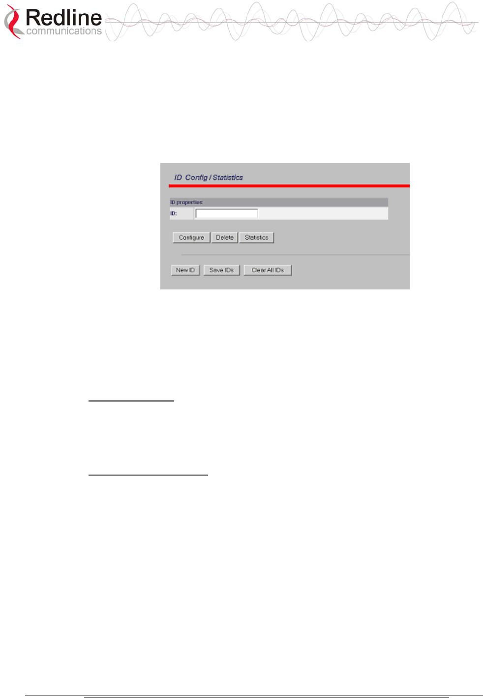
AN-50e
user manual
70-00033-02 Proprietary Redline Communications © 2004 November 2004
Page 57 of 96
6.3.2 PMP - ID Configuration and Status
The ID Configuration and Status page provides a simple to use Graphical User
Interface (GUI) for the operator to configure all channel parameters. Click the
Save IDs in Flash button at the bottom of this page to save changes in non-volatile
memory. These operations are recorded in the system logs.
Figure 23: ID Config / Status
Note: It is important to ensure that all fields on the ID Configuration page are
filled out properly for local and remote terminals. Errors in these fields will result
in the inability to establish a communication link. Please read this section
carefully to ensure a quick, trouble-free deployment.
ID Properties
ID: Select the channel ID to be configured, deleted or displayed for the system in
which you are interested. If the ID number is not known, click the ID Browser
menu (left side of screen) to locate the required ID number.
ID Screen Buttons
Configure: Calls the Link Configuration screen for the selected ID (master-end
system only).
Delete: Delete the selected ID (master-end system only).
Statistics: Display the Link/Connection Status screen for the selected ID.
New ID: Add a new ID by opening the Link Configuration screen (master-end
system only).
Save IDs: Save all IDs (master-end system only).
Clear All IDs: Clears all IDs from the the ID tables (master-end system only).
This process cannot be undone.
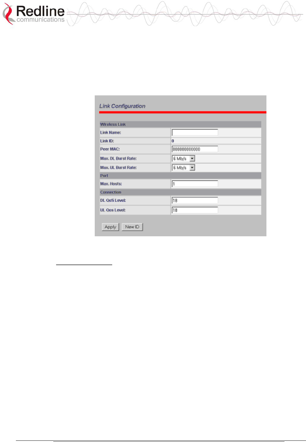
AN-50e
user manual
70-00033-02 Proprietary Redline Communications © 2004 November 2004
Page 58 of 96
6.3.3 PMP - Link Configuration
This screen is displayed through the ID Config / Status screen by clicking the
Config button. The fields in the Link Configuration screen need to be filled out for
each individual subscriber station. This function is available only at the master -
end system.
Figure 24: Link Configuration
Wireless Link
Link Name: A user specified alphanumeric identifier for the link. The name
remains with the system, even during power-off states, until the operator re-types a
new name using this menu field. This field is limited to 8 characters.
Link ID: Automatically generates a numeric ID for the specified link name. For a
new link, the default ID is always zero. After saving the parameter on the Link
Configuration screen, the AN-50e system will automatically choose a link ID other
than zero. Use the ID Browser to search for a link name and the associated Link
ID.
Peer MAC: Enter the MAC address of the subscriber station to register the remote
unit. If the MAC address is not properly entered, the wireless link will not be
established and no Ethernet packets can be transferred.
Max. DL Burst Rate: Maximum downlink (DL) burst rate. Specifies the
maximum downstream burst rate Base Station can use to send data to this
Subscriber Station.
Max UL Burst Rate: Maximum uplink (UL) burst rate. Specifies the maximum
upstream burst rate this Subscriber Station can use to send data to the Base Station.

AN-50e
user manual
70-00033-02 Proprietary Redline Communications © 2004 November 2004
Page 59 of 96
Port
Max Host: Defines the maximum number of hosts (i.e., PCs, …etc) to be learned
from the corresponding Subscriber Station.
Connection
DL QoS Level: Enter the downlink QoS level.
UL QoS Level: Enter the uplink QoS level.
Link Configuration ID
Apply: Saves changes to the current link ID configuration. In order to save Ids
configuration in memory use “Save ID” button in the “ID Config/Status” screen.
Otherwise, all the Ids changes made since the last reboot will be lost.
New ID: Save current ID configuration under a new Link Name.
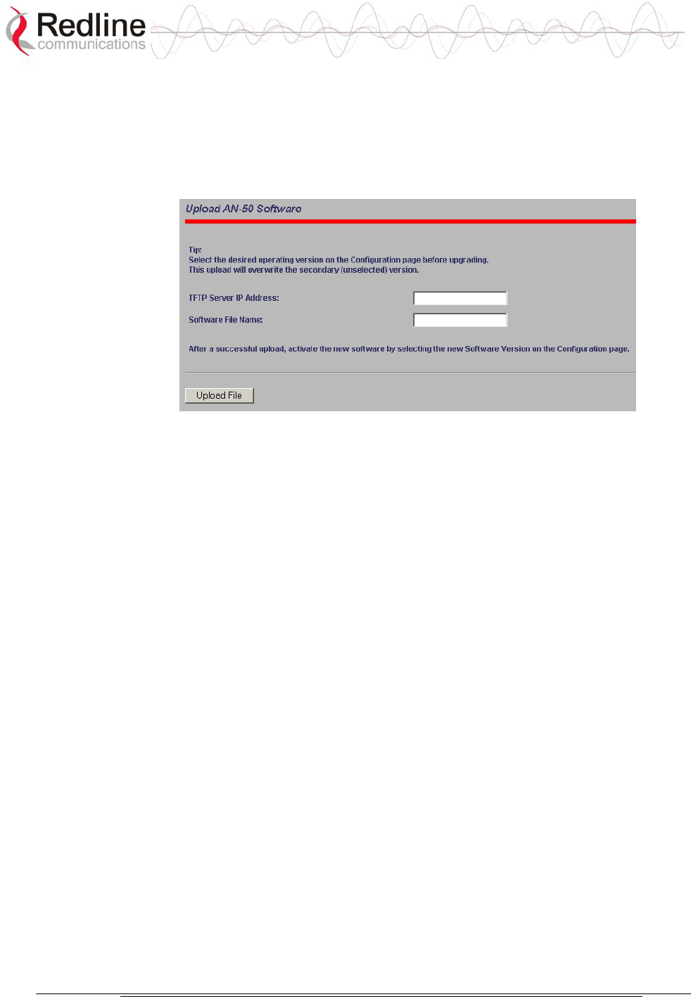
AN-50e
user manual
70-00033-02 Proprietary Redline Communications © 2004 November 2004
Page 60 of 96
6.4 Upload Software
Clicking on Upload Software in the left hand menu will display the Upload AN-
50e Software screen. The upload screen shown is used to upgrade the terminal
with new software stored in a binary file on a server or host computer.
Figure 25: Upload Software Screen
TFTP Server IP Address: IP address of the computer that runs the TFTP server
that contains the upgrade software in binary format.
Software File Name: Name of the binary file including the file extension.
The terminal contains two non-volatile RAM banks for storing two versions of the
software. It is important to select the desired operating version before beginning
the upgrade process, as the upload will always overwrite the non-operational
(unselected) version. Use the System Configuration screen (section 6.2) to select
the current operating version of system software.
The upgrade process is achieved remotely using the Trivial File Transfer Protocol
(TFTP). The operator must fill in two input fields: TFTP Server IP Address and
File Name.
After typing the TFTP Server IP Address and File Name, click the Upload File
button to begin the file transfer. A status screen will display the number of bytes
transferred from the TFTP server to the terminal in real time. The upgrade file size
is approximately 1.8 MB and will take approximately two to four minutes to
download from the server to the terminal memory.
When the file transfer is complete, the terminal will verify the integrity of the new
software. If errors were introduced during the transfer process, the terminal will
reject the new software load and provide a warning that the upgrade was
unsuccessful. In this case, the operator will need to repeat the upload process.
Use the System Configuration screen (section 6.3) to select the current operating
version of system software.

AN-50e
user manual
70-00033-02 Proprietary Redline Communications © 2004 November 2004
Page 61 of 96
6.4.1 Options Key Screen
Clicking on AN-50e Options in the left hand menu will display the AN-50e
Product Options screen. This screen is used to upgrade the terminal with custom
options.
Figure 26: Product Options Screen
The options key controls the availability of functions and default settings on the
AN-50e. This includes maximum Tx power levels and the DFS function.
The key is personalized to each terminal’s MAC address. Please ensure that the
correct MAC address is provided when requesting a key from your local
representative.
Enter the key (case sensitive), ensure it is correct, and click the Activate button.
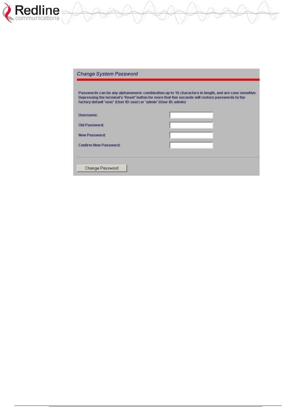
AN-50e
user manual
70-00033-02 Proprietary Redline Communications © 2004 November 2004
Page 62 of 96
6.4.2 System Password Screen
Clicking on System Password in the left hand menu will display the System
Password screen. This screen allows the operator to modify the system passwords.
Figure 27: System Password Screen
The factory default password for the system is 'admin' for the username 'admin'
and 'user' for the username 'user'. To change the password, enter the username and
the old password. Enter a new password in the two lower fields using any
alphanumeric combination. Note the field is case sensitive and can be up to sixteen
characters in length.
Username: Enter user name.
Old Password: Enter current password.
New Password: Enter new password.
Confirm New Password: Re-enter new password (avoids typing errors).
Note: The original factory default passwords can be restored by depressing the
front panel Reset button for more that five seconds. This will also reset the
configuration to the factory default settings. The software version is not effected.
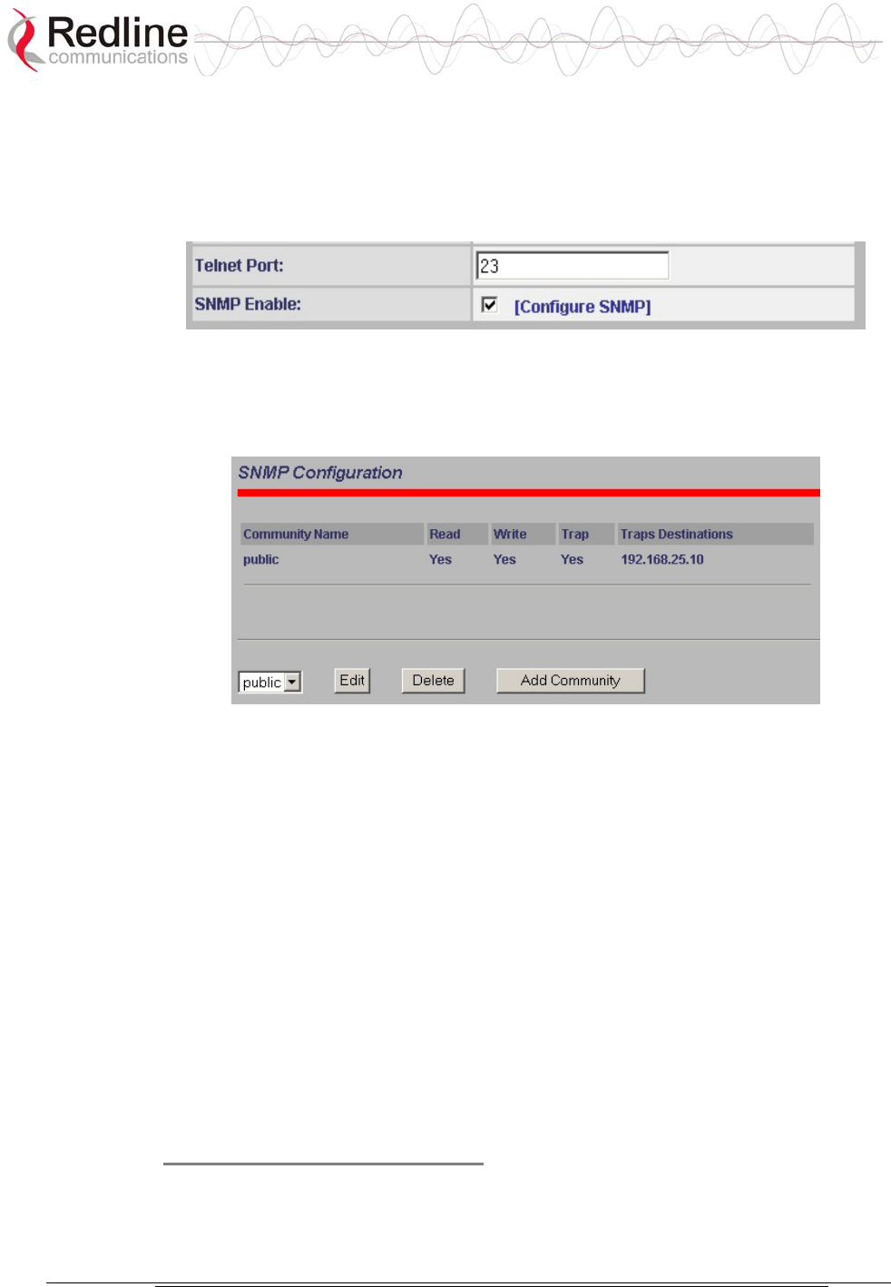
AN-50e
user manual
70-00033-02 Proprietary Redline Communications © 2004 November 2004
Page 63 of 96
6.4.3 SNMP Settings Screen
Click Configure SNMP (blue text) on the System Configuration screen to view
and edit the SNMP settings. The blue text will only appear if the SNMP Enable
box is checked.
Figure 28: System Configuration Screen - SNMP Access
The SNMP Configuration screen displays a list of the current communities. The
control buttons can be used to add, edit or delete communities.
Figure 29: SNMP Configuration Screen
SNMP Configuration: The list of defined communities is displayed in the
Community Name table.
Edit: Select a community from the pull down menu and click the Edit button to
modify an existing community. The Community Configuration/Trap Configuration
screen will be displayed.
Delete: Select the community from the pull down menu (bottom left of screen) and
then click the Delete button to delete that community. Note that it is not possible to
delete the public SNMP community, but the access level can be changed.
Add Community: Click the Add Community button to add a new community.
The Community Configuration/Trap Configuration screen will be displayed.
Add Community: To add a new community, click Add Community button. The
Community Configuration/Trap Configuration screen will be displayed.
Community Configuration:
Community Name: The SNMP community name. After clicking Save, this name
will appear in the drop down list on the main SNMP Configuration screen.
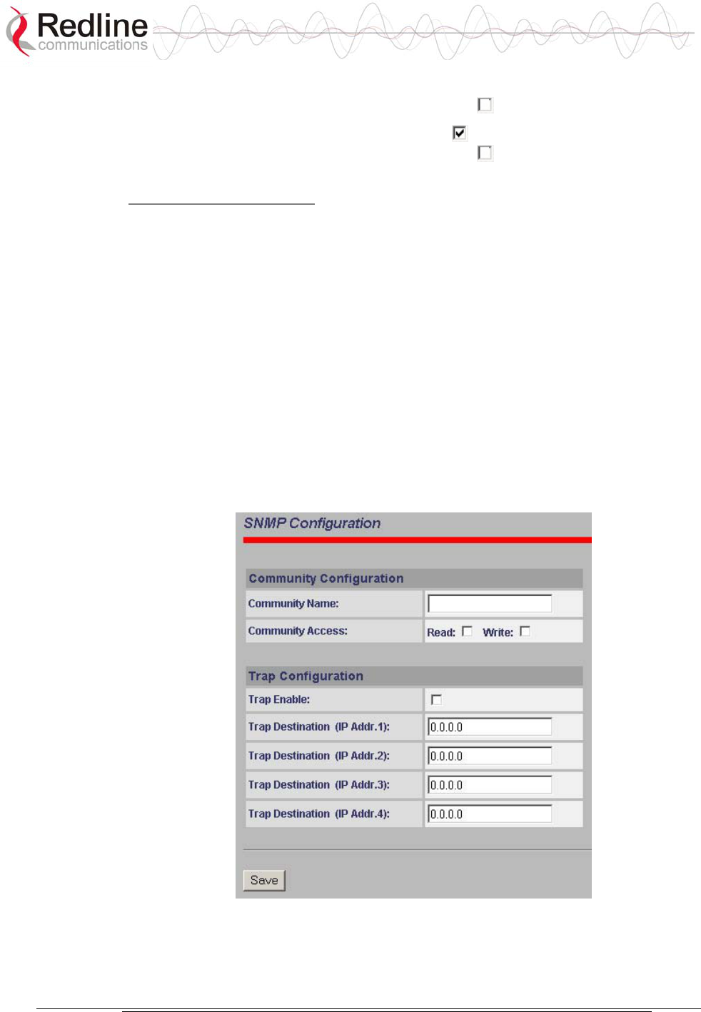
AN-50e
user manual
70-00033-02 Proprietary Redline Communications © 2004 November 2004
Page 64 of 96
Community Access - Read: Check the Read box to grant read access permission
to members of this community. Uncheck this box ( ) to deny read permission.
Community Access - Write: Check this box to grant write access permission
to members of this community. Uncheck this box ( ) to deny write permission.
Trap Configuration:
Trap Enable: When the SNMP Agent in the terminal detects an error condition, a
message known as a trap is sent. A Trap Host is an IP system/server that is set up
to receive SNMP trap messages. Checking this option enables sending traps.
Trap Destination (IP Addr. 1): Enter the IP address of the Trap Host in dotted
decimal format. At least one (1) IP address is required.
Trap Destination (IP Addr.2): Enter the IP address of the Trap Host in dotted
decimal format. This address may be left blank.
Trap Destination (IP Addr. 3): Enter the IP address of the Trap Host in dotted
decimal format. This address may be left blank.
Trap Destination (IP Addr. 4): Enter the IP address of the Trap Host in dotted
decimal format. This address may be left blank.
Save: Click Save to permanently save the current parameters and return to the
main SNMP configuration screen.
Figure 30: SNMP Community/Trap Settings Screen
AN-50e
user manual
70-00033-02 Proprietary Redline Communications © 2004 November 2004
Page 65 of 96
Chapter
7
7
7
D
Di
ia
ag
gn
no
os
st
ti
ic
cs
s
a
an
nd
d
T
Tr
ro
ou
ub
bl
le
es
sh
ho
oo
ot
ti
in
ng
g
Troubleshooting can be performed using the front panel LEDs and the host
computer/server connected locally or remotely to the terminal.
Important: Before beginning any troubleshooting via the front panel, check that all
cables are securely attached. Also verify that all fields on the System
Configuration page are correct for both the local and remote-end terminals (entry
errors in these fields may cause the terminal to be unable to establish a
communication link).
This section provides basic diagnostic and troubleshooting procedures to help
solve problems that may occur with the system. If, after reading this section, you
are unable to get the system operating properly, please contact your local Redline
representative. Include the model name and serial number of the system (located
on the back of the terminal) in your communications.
7.1 Factory Default Settings
The following parameters are the factory default setting for the terminal.
Table 15: Factory Default Settings
Section Item Factory Default Setting
System User Name admin
Password admin
Ethernet IP Address 192.168.25.2
Subnet Mask 255.255.255.0
Gateway 0.0.0.0
Wireless RF Channel Set by factory key.
Tx power 14 dBm
Encryption Disabled / no key

AN-50e
user manual
70-00033-02 Proprietary Redline Communications © 2004 November 2004
Page 66 of 96
7.2 Front Panel Diagnostics
The front panel of the terminal includes a LAN interface and three groups of status
indicators to help with first level diagnoses of problems encountered with the
terminal.
Figure 31: Front Panel LEDs
System Reset Button
Throughout this section, reference is made to the Reset button, which is a micro-
switch recessed in the front panel in the system block. Use a small narrow object,
such as a paper clip, to access the button.
Depressing the button for less than five (5) seconds will activate a short reset,
which is equivalent to turning the terminal off and on. Statistical values are reset,
and the currently loaded software / firmware will be retained. Note that a short
reset may be accomplished remotely by clicking on the System Reboot button
from System Configuration screen.
Depressing the Reset button for more than five (5) seconds executes a long reset.
A long reset reloads the factory default configuration settings such as IP Address,
IP Subnet Mask, Channel, System Name, Passwords and restarts the system. The
software version that existed in the system before the long reset is retained.
An example of when a long reset will help is in the event that a password or IP
address is forgotten. The long reset function will simply restore the system back to
its original factory default settings. A long reset is confirmed by the Wireless Link
LED flashing three times, followed by the LED power-up sequence:
All Ethernet LEDs light for one second, then individual Ethernet LEDs blink twice
in the following order: FD/Col, 100, and Link/Act. The Fault LED lights for
approximately four seconds, then turns off. The two Wireless LEDs remain off for
approximately five seconds, and then blink once. Following this sequence, all
LEDs will indicate the current operational status.
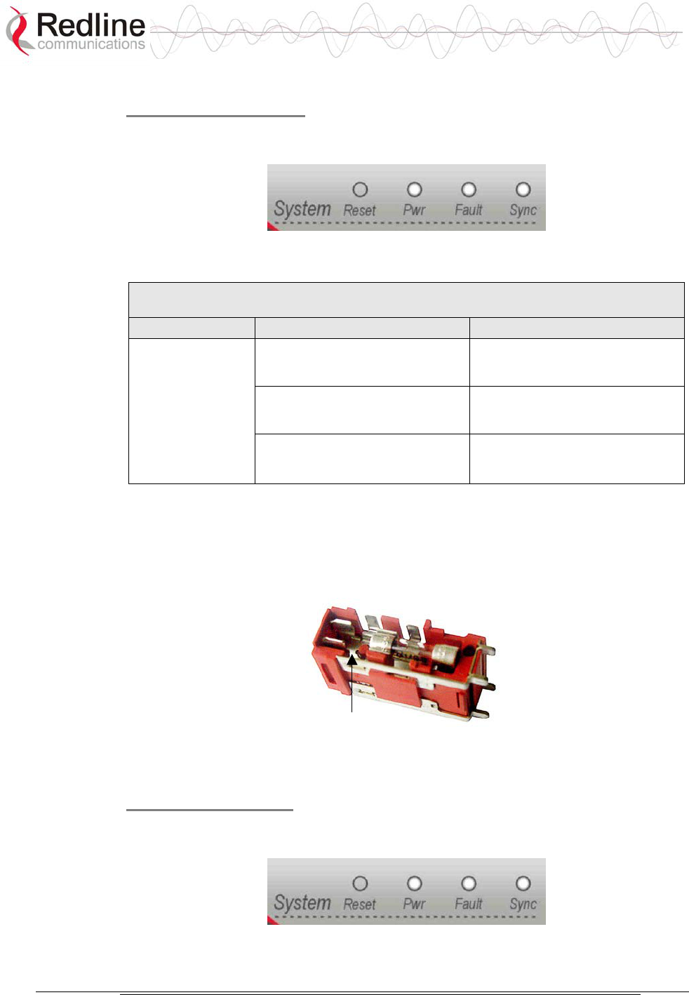
AN-50e
user manual
70-00033-02 Proprietary Redline Communications © 2004 November 2004
Page 67 of 96
System Power LED
If the Pwr LED is not illuminated solid green, power is not getting to the terminal.
The most probable causes are:
Figure 32: Front Panel: System Pwr LED
Table 16: System Power Diagnostics
Symptom Possible Problem Solution
On/Off switch in Off
position
Turn on switch at back of
terminal.
Fuse blown Replace fuse. (spares are
provided)
Pwr LED
does not
illuminate
Power cord disconnected Securely connect cord to
terminal and outlet.
To replace a fuse, pry off the black plastic cover located on the back panel beside
the power switch, and extract the red fuse holder. Be certain to replace the fuse(s)
into the lower half of the holder, as shown in the diagram below. The fuse holder
holds two fuses, both of which are active. Be certain to use fuses of the same type
and rating.
Note space
Figure 33: Fuse Holder
System Fault LED
If the Fault LED lights solid red, it is an indication that there is a serious problem
with the system software or hardware.
Figure 34: Front Panel: System Fault LED
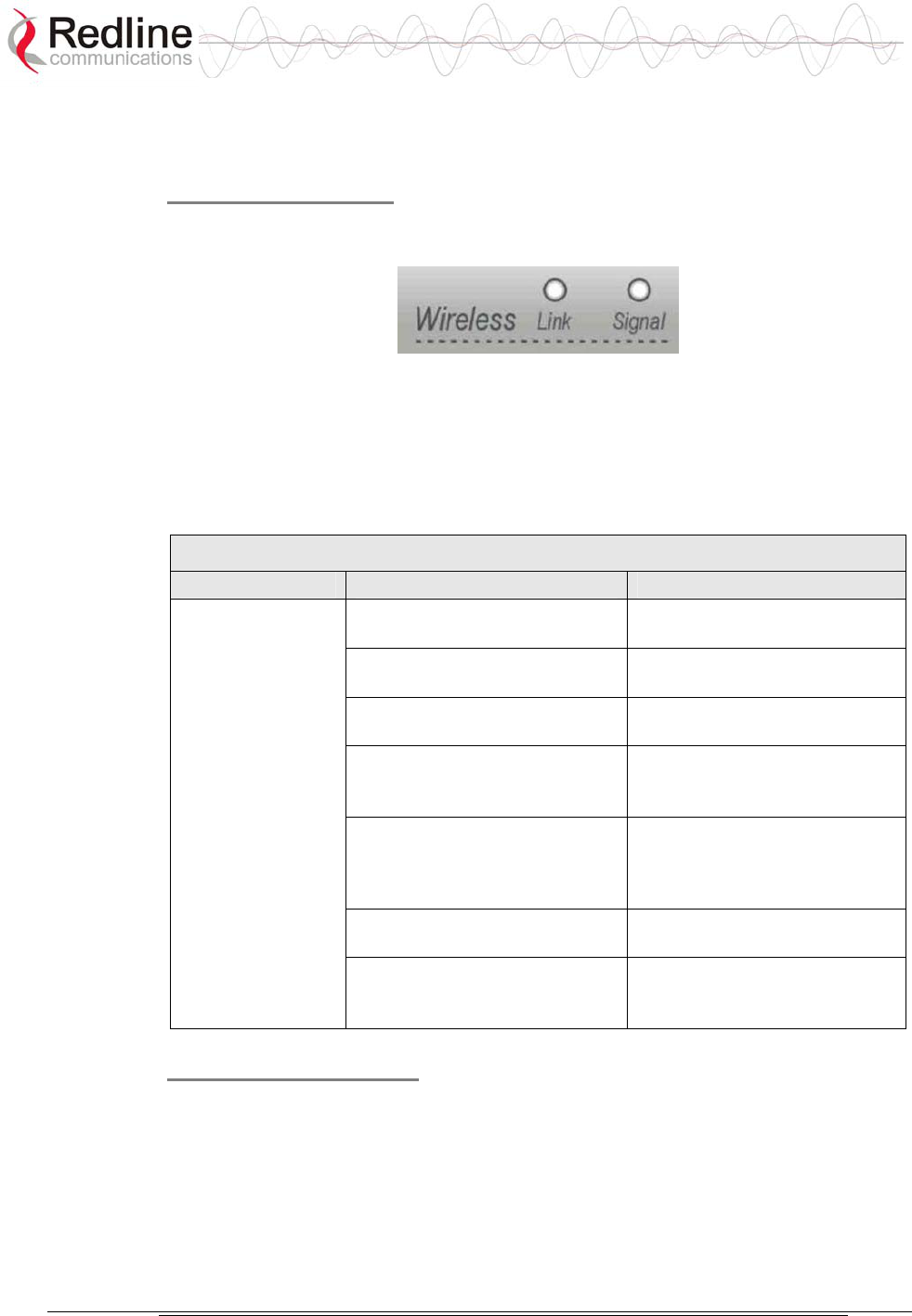
AN-50e
user manual
70-00033-02 Proprietary Redline Communications © 2004 November 2004
Page 68 of 96
Check the IF cable. A short or long reset may fix the problem. If not, contact your
local representative. Also refer to the System Logs screen and RF Status codes.
Wireless Link LED
The Wireless Link LED lights solid green when the wireless link is established to
the remote-end terminal.
Figure 35: Front Panel - Wireless Link LED
When the Link LED is off, it is an indication there is a problem with either the
terminal link, radio, or with the actual propagation path itself. Check the RF Status
parameters in the System Status screen. Table 17: Wireless Link Diagnostics
following lists some of the potential causes.
Table 17: Wireless Link Diagnostics
Symptom Possible Problem Solution
Remote-end terminal is not on
or is malfunctioning.
Verify operation of remote-end
terminal.
The propagation path is
blocked.
Clear path or re-locate
antennas.
The transceiver is mal-
functioning.
Repair or replace transceiver
Antenna has moved and is no
longer aligned with remote-end
terminal.
Re-align the antenna.
Cable between transceiver and
antenna or between transceiver
and terminal not properly
connected.
Properly secure cables.
Power not getting to the
transceiver from the terminal.
Repair or replace terminal.
No wireless link
(Link LED does
not illuminate)
Receiver and transmitter have
been set to different RF
channels.
Make sure both terminals are
operating on the same RF
channel.
Wireless Signal LED
When Adaptive Modulation is enabled, the Wireless Signal LED will light solid
green if the system is operating at or above the configured Uncoded Burst Rate,
and will flash when the system is operating at a lower order modulation scheme
(i.e., the current Uncoded Burst Rate is lower than the configured Uncoded Burst
Rate). If the system cannot maintain the lowest modulation scheme due to link
errors, the Signal LED will turn off.
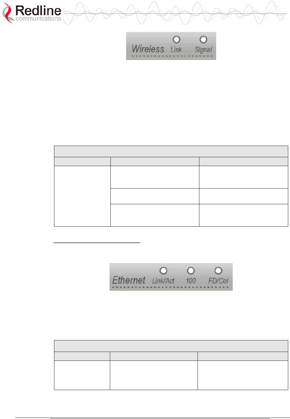
AN-50e
user manual
70-00033-02 Proprietary Redline Communications © 2004 November 2004
Page 69 of 96
Figure 36: Front Panel - Wireless Signal LED
When Adaptive Modulation is disabled, the Wireless Signal LED will light solid
green if the system is operating at an error rate of less than one out of one million
packets. If errors exceed one in one million, the LED will flash. If the wireless link
becomes poor, the LED will turn off.
Flashing may not be a serious problem if the LED flashes only intermittently,
however, if it flashes constantly refers to the following table for some of the
possible causes.
Table 18: Wireless Signal Diagnostics
Symptom Possible Problem Solution
Obstructions in the
propagation path causing
signal degradation.
Try to remove obstacles or re-
locate antenna.
Antenna moved, due to high
winds.
Re-align the antenna.
Weak RF Link
(Signal LED
flashes)
Poor cable connection
between transceiver and
antenna.
Repair or replace the RF cable.
Ethernet Link/Act LED
The Ethernet Link/Act LED will light when the LAN connection to the host
computer/server or switch/router is functioning properly.
Figure 37: Front Panel: Ethernet Link/Act LED
The Link/Act LED flashes when the LAN connection to the host computer/server
or switch/router is functioning properly and there is traffic. If the LED is off, look
for the following problems:
Table 19: Ethernet Link/Act Diagnostics
Symptom Possible Problem Solution
No Ethernet Link
(Link/Act LED off)
Poor cable connection
between terminal and
computer/server or between
terminal and switch/router.
Carefully check all cable
connections.
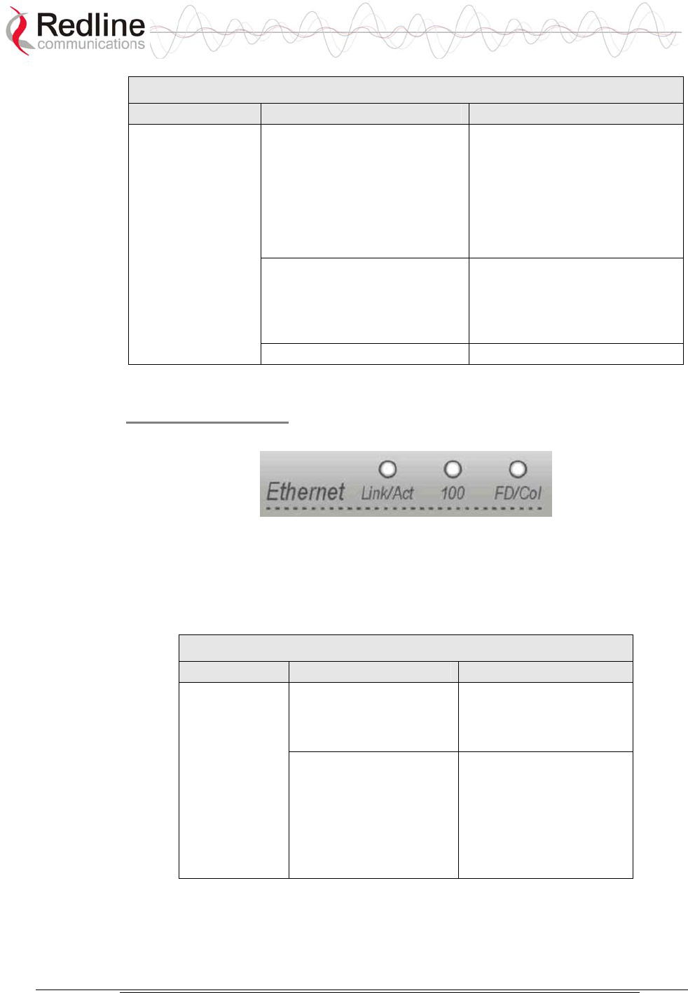
AN-50e
user manual
70-00033-02 Proprietary Redline Communications © 2004 November 2004
Page 70 of 96
Table 19: Ethernet Link/Act Diagnostics
Symptom Possible Problem Solution
Wrong type of Ethernet cable
between terminal LAN port
and host computer/server or
switch/router.
If the terminal LAN port is
connected to a host computer
or server directly, then ensure a
straight-through cable is used.
Otherwise, to connect the
terminal to a switch or router,
ensure a crossover cable is
used.
The auxiliary Network
equipment including
switch/router, host
computer/server, may be
malfunctioning.
Repair or replace faulty
terminals.
Processor malfunction. Try short reset or long reset.
Ethernet 100 LED
The Ethernet 100 LED is on when the link is operating at 100Base-T.
Figure 38: Front Panel: Ethernet 100 LED
Note that when connected to a hub, it is typical for packet collisions to occur
intermittently. On a Half-Duplex link, there will be collisions. Some causes
include:
Table 20: Ethernet 100 Diagnostics
Symptom Possible Problem Solution
Ethernet connection
manually set for
10Base-T operation.
Change Ethernet Mode
setting to Auto or 100 in
the System Configuration
web screen.
Ethernet Link
100 LED off
The connected Ethernet
device may be operating
at 10Base-T.
If the terminal LAN port is
connected to a host
computer or server
operating at 10Base-T,
you may have to change
the settings for that
device.
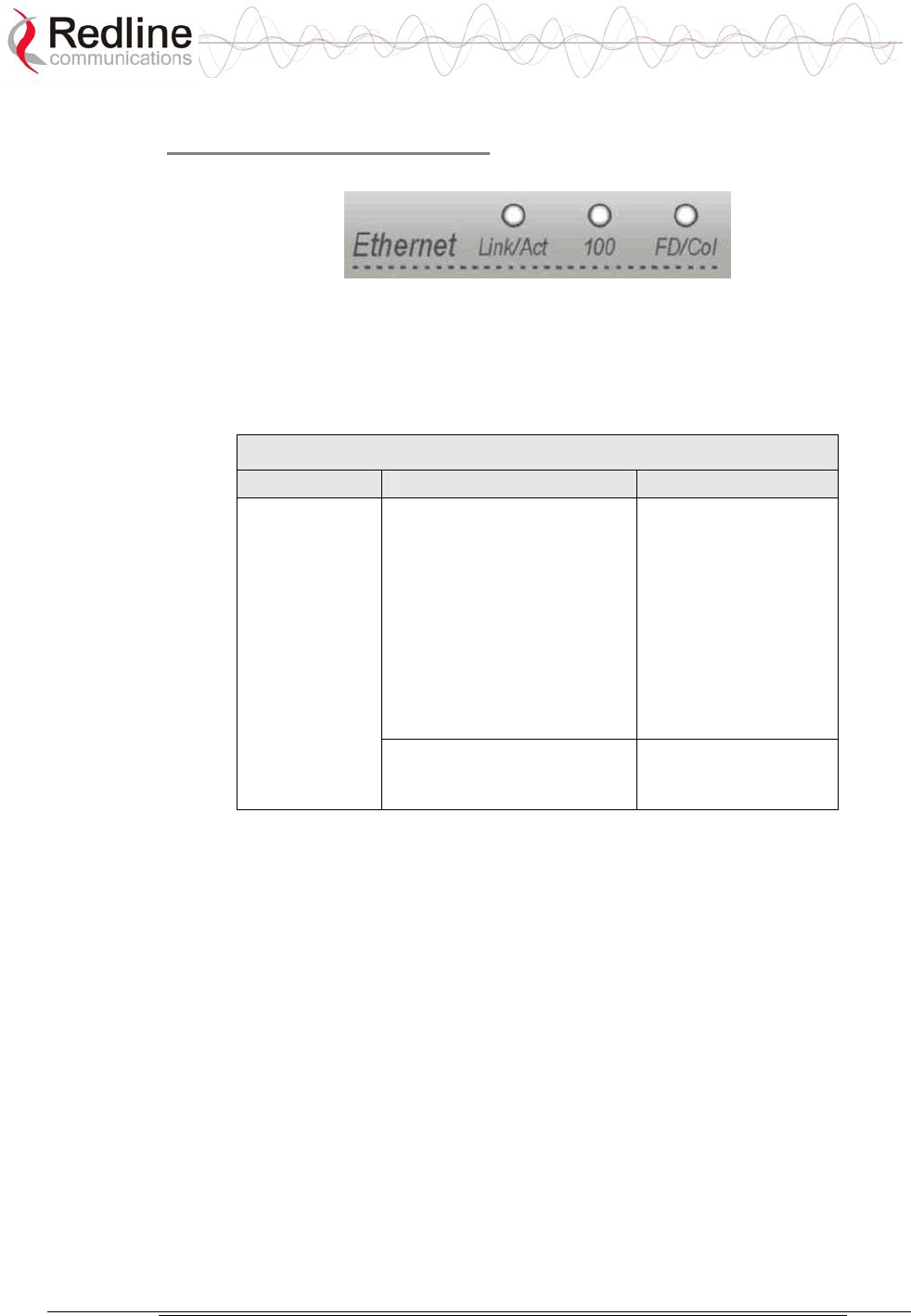
AN-50e
user manual
70-00033-02 Proprietary Redline Communications © 2004 November 2004
Page 71 of 96
Ethernet FD/Collision LED
The Ethernet FD/Col LED flashes when packet collisions occur over the LAN.
Figure 39: Front Panel: Ethernet FD/Col LED
Note that when connected to a hub, it is typical for packet collisions to occur
intermittently. On a Half-Duplex link, there will be collisions. Some causes are
listed in the following table.
Table 21: Ethernet Collision Diagnostics
Symptom Possible Problem Solution
Collisions are normal for
Half Duplex links. However,
if the terminal is connected
to is not configured for auto-
negotiation, but manually
set for Full Duplex, then the
terminal will not be able to
negotiate this mode and will
stay set to Half Duplex. This
results in CRC errors on the
network device port.
Change the
configuration from
hard coded Full
Duplex to auto-
negotiation
Link Collision
(FD/Col LED
flashes)
Incompatible Ethernet port
speed.
Confirm speed and
duplex mode of
devices.

AN-50e
user manual
70-00033-02 Proprietary Redline Communications © 2004 November 2004
Page 72 of 96
7.3 Troubleshooting the Web Interface
These troubleshooting hints assume that the status LEDs on the front panel of the
terminal indicates normal functionality.
Table 22: Web Interface Diagnostics
Symptom Possible
Problem
Solution
Incorrect IP
address and/or
Subnet Mask.
Perform a ping test from the host computer
command line.
If the ping test is unsuccessful, then the problem
is with the IP address. Perform a long reset to
apply the default address (192.168.25.2) and
Subnet Mask (255.255.255.0)
Problems with
host computer, or
terminal.
If the ping is successful try a short reset of the
terminal, and/or reboot the host computer.
Home Screen
(General
Information)
cannot be
accessed.
Host PC ARP
table is
incorrectly
configured
Run 'arp:d' whenever the terminal is swapped.
Check that the subnet mask for the host PC
matches the subnet mask of the terminal. Check
that the host PC's address is 192.168.25.n,
where 'n' is not equal to 0,2, or 255.
Attempt to login to the terminal using a Web browser. Microsoft Internet Explorer
is recommended. If the terminal does not respond by displaying the login dialog
box, check that the correct IP address is being used. The value 192.168.25.2 is the
factory default value and may have been changed during installation.
The next test is to verify the IP address is reachable from the computer. Use the
ping command to test the connection between the terminal and host computer. The
system will always respond to ping frames less that 577 bytes in length.
>Ping 192.168.25.2
If the ping test is successful, the host computer was able to send and receive
packets to/from the terminal. The problem may be with the Internet browser or
related settings on the host computer. Re-boot the host computer to try to resolve
the problem.
If the ping is unsuccessful, there may be problems using that IP address; the IP
address may be incorrect, or there may be a duplicate address. For correct
operation the host computer and the terminal must appear to be on the same
subnet. For example, if the terminal is using the factory default settings, the host
computer could be set for an IP of 192.168.25.3 and a subnet mask of
255.255.255.0.
If the correct IP address of the terminal cannot be determined, it is recommended
to perform a long reset to restore the terminal to the default value.
Warning: performing a long reset will restore the terminal's IP address
(192.168.25.2) and IP Subnet Mask (255.255.255.0) to the factory default value.
AN-50e
user manual
70-00033-02 Proprietary Redline Communications © 2004 November 2004
Page 73 of 96
7.4 Troubleshooting The RF
RF Error Codes
The terminal monitors the status of the outdoor transceiver unit and reports any
fault conditions in the system logs.
Table 23 lists the general fault conditions are reported by the system.
Table 23: RF Errors
Error Type Description
AN-50e PLL Error The PLL (Phase Locked Loop) section within the terminal
experienced an error. The System Fault LED may light. Try
resetting the terminal.
Communication Error
Over IF Cable
Communication between the terminal and the transceiver
failed. Check the IF cable and connectors.
Radio High Temp.
Warning
The transceiver’s internal temperature rose above 185F / 85C.
The transceiver will shut down for 30 seconds to allow cooling
time.
Radio Power Supply
Fault
Indicates a fault in the transceiver’s power supply. This error
could be due to a problem with the internal power supply, or
with the power source from the terminal. If the Low DC Voltage
At Radio error is also indicated, (see below) check the IF cable
and connectors. If the Low DC Voltage At Radio error is not
indicated, the transceiver will require servicing.
Low DC Voltage At
Radio Input
The DC voltage at the transceiver (carried by the IF cable from
the terminal) is lower than the required 24 VDC. Check the IF
cable and connectors. The minimum required voltage for
operation is 12 VDC.
See Table 24: RF Status Error Codes for a list of the thirty-two possible error
codes.
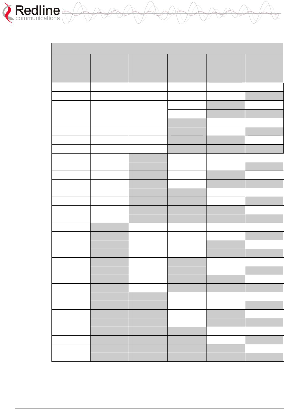
AN-50e
user manual
70-00033-02 Proprietary Redline Communications © 2004 November 2004
Page 74 of 96
Table 24: RF Status Error Codes
Error Code Terminal
PLL Error
Comm
Error Over
IF Cable
Radio
High Temp.
Warning
Radio
Power
Supply
Fault
Low DC
Voltage At
Radio Input
0 No Errors No Errors No Errors No Errors No Errors
1
X
2
X
3
X X
4
X
5
X X
6
X X
7
X X X
8 X
9 X
X
10 X X
11 X X X
12 X X
13 X X X
14 X X X
15 X X X X
16 X
17 X
X
18 X
X
19 X
X X
20 X X
21 X X X
22 X X X
23 X X X X
24 X X
25 X X
X
26 X X X
27 X X X X
28 X X X
29 X X X X
30 X X X X
31 X X X X X

AN-50e
user manual
70-00033-02 Proprietary Redline Communications © 2004 November 2004
Page 75 of 96
7.5 System Error Log Messages
The following table provides a brief description of the key messages recorded in
the logs by the system.
Table 25: System Log Messages
Log Message Description
100-Parameters loaded
successfully!
All system parameters have been successfully downloaded.
101-Firmware configuration OK! The onboard firmware configuration has been properly set
up.
102-Ethernet port configured! The Ethernet port has been properly configured and is
operational.
103-Parameters saved
successfully!
The latest configuration parameters have been successfully
saved into the system memory.
104-Upgrade OK! The software upgrade process completed successfully.
105-Password changed
successfully!
The system password was successfully changed.
106-Firmware programmed OK! The firmware was successfully programmed.
107-Statistics initialized! Reset of statistics was successful.
108-Version control loaded
successfully!
Software version control data was successfully loaded.
109-Options Key activated! Product Options Key was accepted.
110-Options Key already used! The Product Options Key was not accepted because it was
already used once. Contact your local Redline
representative.
111-SNMP configuration loaded
successfully!
The SNMP configuration was successfully loaded.
201-EEPROM corrupted. Def.
param. loaded!
The memory area containing the system configuration has
been corrupted. Default parameters loaded.
202-Error while saving
parameters!
The latest configuration parameters have not been
successfully saved. In this case, repeat the save
configuration process to try to resolve the problem.
203-Another upgrade in
progress!
The system is already in upgrade mode, in the event the
operator inadvertently invoked multiple simultaneous
upgrades.
204-Invalid upgrade parameters! The parameter entered is in error. If this message appears,
check for typing errors.
205-Upgrade failed! The software upgrade process completed unsuccessfully.
206-Password changed
unsuccessfully!
The new password entered into the system was not
successful. In this case, repeat the process.
207-Timeout on reading data
packet!
The system has timeout looking for packets from the host
computer or server. Check for obvious problems such as
disconnected or faulty cable.
209-TFTP error received! The Trivial File Transfer Protocol (TFTP) routine used to
download the software to the terminal during the Upgrade
process failed. Likely cause is disconnected or faulty cable.
210-Error: TFTP unknown
message!
The TFTP client received an unknown message. In this
case, repeat the upgrade process.
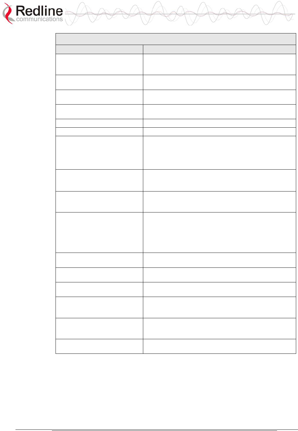
AN-50e
user manual
70-00033-02 Proprietary Redline Communications © 2004 November 2004
Page 76 of 96
Table 25: System Log Messages
Log Message Description
211-Error: while writing flash!
While writing the new software into terminal flash memory
an unexpected error occurred. Try to repeat the process and
if the error persists contact your local representative.
212-Error firmware configuration! An unexpected error occurred while writing the onboard
firmware configuration. Try to repeat the process.
213-Firmware programming
failed!
The firmware programming failed.
214-Error while loading version
control!
Software version control data was not loaded successfully.
215-Log buffer full! The log buffer overflowed.
216-Invalid Options Key! User entered an invalid Product Options key.
217- PLL unlocked! One or more RF synthesizers unlocked. The unit stopped
RF transmissions and attempted to reprogram the
synthesizers. If this message repeats or if the RF link is not
back on, try to reset the terminal. If the problem persists,
contact customer support.
218-Outdoor unit over
temperature!
The internal temperature of the transceiver is above 185F /
85C. The transceiver will shut down for 30 seconds to allow
cooling.
219-Excessive DC loss on IF
cable!
The DC voltage at the transceiver (carried by the IF cable
from the terminal) is lower than the required 24 VDC. Check
the IF cable and connectors.
220-Outdoor unit power supply
fault!
Indicates a fault in the transceiver's power supply. This error
could be due to a problem with the internal power supply, or
with the power source from the terminal. If the 'Excessive
DC loss on IF cable' error is also indicated, check the IF
cable and connectors. If not, the transceiver will require
servicing.
221-\public\ community can't be
deleted!
The default 'Public' SNMP community cannot be deleted.
222-Max. community number
already defined!
No more communities may be defined, as the maximum
number has been reached
223-Community name already
defined!
The name for the SNMP community has already been used.
Choose another name.
224-MIB initialization error! MIB construction process generated an error. Try to reset
the terminal. If the problem persists, contact customer
support.
225-Error while loading SNMP
configuration!
EEPROM memory was corrupted and the SNMP
configuration couldn't be loaded. Default SNMP
configuration was loaded.
226-Error while saving SNMP
configuration!
SNMP configuration saving process wasn't successfully. Try
again. If the problem persists, contact customer support.

AN-50e
user manual
70-00033-02 Proprietary Redline Communications © 2004 November 2004
Page 77 of 96
7.6 Saving System Parameters
The AN-50e is a highly configurable communications device. All configurable
options are saved in NVRAM (programmable flash ROM).
There are a number of steps required for editing and activating changes to the
personalization of each terminal. The following table describes the basic
operations available and how to control selection of the parameters and operation
of the terminal.
The Test button is located in the System Configuration page. You must click the
Save button at the bottom of the System Configuration screen to save these system
parameter settings in the NVRAM.

AN-50e
user manual
70-00033-02 Proprietary Redline Communications © 2004 November 2004
Page 78 of 96

AN-50e
user manual
70-00033-02 Proprietary Redline Communications © 2004 November 2004
Page 79 of 96
Chapter
8
8
8
A
Ap
pp
pe
en
nd
di
ix
x
8.1 System Specifications
Table 26: AN-50e Technical Specifications
Wireless System
System Capability: LOS, Optical-LOS, and Non-LOS
RF Band: T-54 Radio: 5.470 GHz to 5.725 GHz1
T-58 Radio: 5.725 GHz to 5.825 GHz1
T-58e Radio: 5.725 GHz to 5.850 GHz1
Center Frequency Steps: 5 MHz
Channel Size: 20 MHz
RF Dynamic Range: > 50 dB
Data Rate: Up to 49 Mbps average Ethernet rate
Max TX Power: -20 dBm to 20 dBm (region specific)2
Rx Sensitivity: -86 dBm @ 6 Mbps (based on BER of 1x10e-9)
IF Cable: Multiplexed IF, DC, control (Tx/Rx, AGC, APC)
Up to 68 m (225 ft) using RG-6U cable3
Up to 228 m (750 ft) using high-grade cable3
Network Attributes: 802.1p network traffic prioritization4
802.3x Ethernet flow control4
Automatic Link Distance Ranging4
DHCP pass-through
Transparent bridge
VLAN pass-through
Dynamic Channel Control: Dynamic Frequency Selection (DFS), Automatic
Transmit Power Control (ATPC)
Modulation/Coding Rates: Adaptive Modulation (bi-directional burst to burst) auto
selects; 1/2 BPSK, 3/4 BPSK, 1/2 QPSK, 3/4 QPSK,
1/2 16 QAM, 3/4 16 QAM, 2/3 64 QAM and 3/4 64
QAM
Over The Air Encryption: 64-bit private key encryption
MAC: PTP and PMP deployment
TDMA
Concatenation/Fragmentation5
Automatic Repeat Request (ARQ) error correction
Dynamic adaptive modulation (BPSK to 64 QAM)
Range: Up to 25 km (15 mi) line-of-sight @ 33 dBm EIRP (for
Europe)
Up to 80 km (50 mi) line-of-sight @ 48 dBm EIRP
Network Services: Transparent to 802.3 services and applications
Duplex Technique: Dynamic TDD (time division duplex)
Wireless Transmission: OFDM (orthogonal frequency division multiplexing)

AN-50e
user manual
70-00033-02 Proprietary Redline Communications © 2004 November 2004
Page 80 of 96
Table 26: AN-50e Technical Specifications
Network Connection: 10/100 Ethernet (RJ-45)
System Configuration: HTTP (Web) interface, SNMP
CLI via Telnet and local console
Network Management: SNMP: standard and proprietary MIBs
Full management by RedAccess NMS
Power Requirements: 39 W maximum
Single/dual auto-sensing 110/220/240 VAC 50/60 Hz
Single/dual 18 - 72 VDC
Redundant Power: Optional dual AC or dual DC power supply (dual cord)
with automatic fail-over
Compliance: EN 60950, EN 301 893, EN 301 390, EN 301 489-1 &
17, FCC part 15
Operating Temperature: IDU Operating Cond.: 5 C to 40 C,
IDU Short-Term Cond.: -5 C to 55 C for up to 16 hours
ODU Operating Cond.: -40 C to 60 C
Dimensions/Weight: IDU: 431.8 x 304.8 x 44.45 mm (17 x 12 x 1.75 in)
Weight: 2.5 Kg (5.5 lb)
1In some countries outside of North America, the maximum operational power per
channel with a given antenna is limited in accordance to maximum allowable EIRP
levels for the region.
2Center frequency is dependent on region.
3With two lightning arrestors installed.
4Point-to-Point Mode only.
5Point-to-Multipoint mode only.
Subject to change without notice.
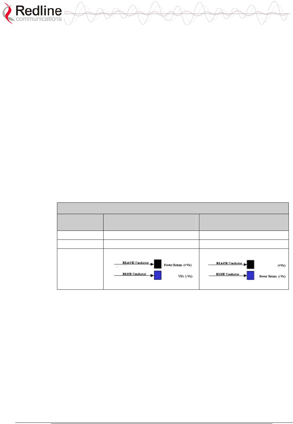
AN-50e
user manual
70-00033-02 Proprietary Redline Communications © 2004 November 2004
Page 81 of 96
8.2 DC Power Supply Cable Connections
This section provides important instructions for connecting to a DC power source.
The DC power supply (optional) is rated for operation using 24, 48 or 60 VDC.
Power is connected to the terminal via a fused power entry module located on the
rear of the terminal. All DC terminals are shipped with a power cord assembly,
consisting of the power entry module’s mating dual pin polarized female plug, pre-
crimped with 18 AWG blue and black insulated wires.
Important: All power wiring must be at least 18 AWG.
The DC power input is floating (+Ve and -Ve not connected to chassis), allowing
positive (minus to ground), negative (positive to ground) and floating power
connections as required. Refer to table below for connection details.
If the terminal does not power-on, it is possible that the blue and black wires are
connected incorrectly resulting in a reversal of polarity. In this event the diode
protection prevents permanent damage to the power supply. Reverse the power
connections and verify that the terminal powers up properly.
Table 27: DC Power Supply Cable Connections
Wire Color Negative DC Power
(-18 to -72 VDC)
Positive DC Power
(+18 to +72 VDC)
Blue Negative power Power Return
Black Power Return Positive Power
Schematics
Note: DC units are not equipped with power switches and activate
immediately when connected to a power source.
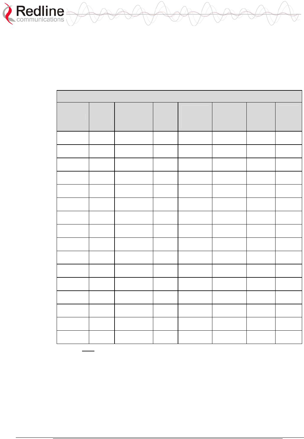
AN-50e
user manual
70-00033-02 Proprietary Redline Communications © 2004 November 2004
Page 82 of 96
8.3 Antenna and Power Specifications
8.3.1 T-58 Radio: Antenna Power Specifications
The system is FCC certified for the antennas listed in the following table.
Table 28: T-58 Radio: Antenna Power Specifications
Redline PN
Ant.
Gain
(dBi)
Antenna Type App.
Minimum
Conducted
Power
(dBm)
Max
Conducted
Power
Ratings
(dBm)
Average
GUI
Power
Display
(dBm)
FCC
Max
EIRP
(dBm)
48-00006 28 Directional
Flat Panel PTP -20 26 20 No
Limit
48-00020 22 Directional
Flat Panel PTP -20 26 20 No
Limit
48-00030 22 Directional
Parabolic PTP -20 26 20 No
Limit
48-00031 28 Directional
Parabolic PTP -20 26 20 No
Limit
48-00032 31.2 Directional
Parabolic PTP -20 26 20 No
Limit
48-00033 34.6 Directional
Parabolic PTP -20 26 20 No
Limit
48-00006 28 Directional
Flat Panel PMP -20 8 2 36
48-00014 15 Directional,
Flat Panel PMP -20 21 15 36
48-00017 14 Directional,
Flat Panel PMP -20 22 16 36
48-00020 23 Directional
Flat Panel PMP -20 13 6 36
48-00028 17 Directional,
Flat Panel PMP -20 19 13 36
48-00029 16 Directional,
Flat Panel PMP -20 20 14 36
48-00030 22 Directional
Parabolic PMP -20 14 8 36
48-00031 28 Directional
Parabolic PMP -20 8 2 36
48-00032 31.2 Directional
Parabolic PMP -20 4 -2 36
48-00033 34.6 Directional
Parabolic PMP -20 1 -5 36
Note: The RF output power and selection must be professionally programmed
and installed by the manufacturer or a trained professional installer for
compliance with FCC requirements of maximum EIRP of 36 dBm.
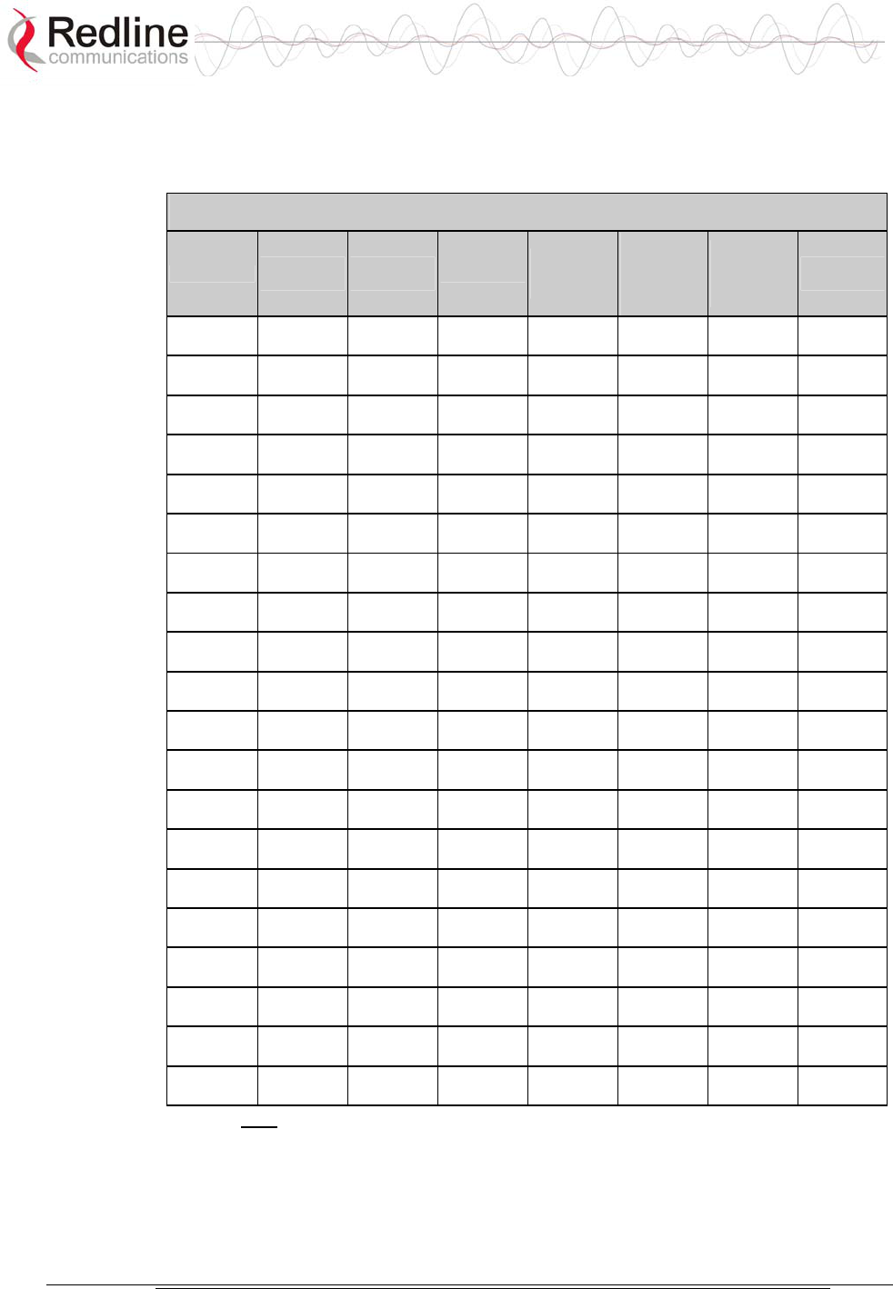
AN-50e
user manual
70-00033-02 Proprietary Redline Communications © 2004 November 2004
Page 83 of 96
8.3.2 T-58e Radio: Antenna Power Specifications
The system is FCC certified for the antennas listed in the following table.
Table 29: T-58e Radio: Antenna Power Specifications
Redline PN Ant. Gain
(dBi)
Antenna
Type App.
Minimum
Conducted
Power (dBm)
Max
Conducted
Power
Ratings
(dBm)
Average GUI
Power
Display
(dBm)
FCC Max
EIRP (dBm)
48-00006 28
Directional
Flat Panel PTP -12.7 26.2 20 No Limit
48-00020 23
Directional
Flat Panel PTP -12.7 26.2 20 No Limit
48-00020-
01 22 Directional
Flat Panel PTP -12.7 26.2 20 No Limit
48-00030 22
Directional
Parabolic PTP -12.7 26.2 20 No Limit
48-00031 28
Directional
Parabolic PTP -12.7 26.2 20 No Limit
48-00032 31.2
Directional
Parabolic PTP -12.7 26.2 20 No Limit
48-00033 34.6
Directional
Parabolic PTP -12.7 26.2 20 No Limit
48-00006 28
Directional
Flat Panel PMP -12.7 8 2 36
48-00014 15
Directional,
Flat Panel PMP -12.7 21 15 36
48-00017 14
Directional,
Flat Panel PMP -12.7 22 16 36
48-00020 23
Directional
Flat Panel PMP -12.7 13 7 36
48-00020-
01 22 Directional
Flat Panel PMP -12.7 14 8 36
48-00028 17
Directional,
Flat Panel PMP -12.7 19 13 36
48-00029 16
Directional,
Flat Panel PMP -12.7 20 14 36
48-00030 22
Directional
Parabolic PMP -12.7 14 8 36
48-00031 28
Directional
Parabolic PMP -12.7 8 2 36
48-00032 31.2
Directional
Parabolic PMP -12.7 4 -2 36
48-00033 34.6
Directional
Parabolic PMP -12.7 1 -5 36
48-00047 15
Directional
Flat Panel PMP -12.7 21 15 36
48-00048 9 Omni-
Directional PMP -12.7 27 20 36
Note: The RF output power and selection must be professionally programmed
and installed by the manufacturer or a trained professional installer for
compliance with FCC requirements of maximum EIRP of 36 dBm.
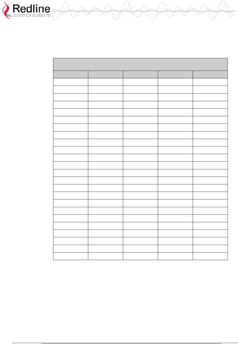
AN-50e
user manual
70-00033-02 Proprietary Redline Communications © 2004 November 2004
Page 84 of 96
8.3.3 T-54 Radio: Maximum RF Power vs. Antenna Gain
The following table provides the adjustment available for maximum RF power
settings based on the angle of deployment. applies to sectorized antennas only.
Table 30: 5.4 GHz Band RF Power vs Antenna Gain
A6017 RWS A9016 RWS A6015 MTS A9014 MTS
deg dBm dBm dBm dBm
0 -1 0 4 2
1 0 1 5 3
2 1 4
3 5
4 6
...
12 2
13 3
14 4
15 5
...
24 6
25 2
26 3
27 4 6
28 5 7
29 6 8
...
32 7
37 8
39 9
...
45 7
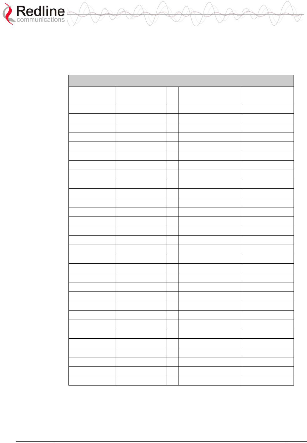
AN-50e
user manual
70-00033-02 Proprietary Redline Communications © 2004 November 2004
Page 85 of 96
8.3.4 Operational Power for T54 (FCC)
The following table provides the maximum RF power settings based on the gain of
the antenna.
Table 31: 5.4 GHz -- Antenna Gain vs Max. Op. Power
Ant. Gain
[dBi]
Max. Power
[dBm]
Ant. Gain
[dBi]
Max. Power
[dBm]
6.0 15 21.0 -1
6.5 15 21.5 -1
7.0 14 22.0 -2
7.5 14 22.5 -2
8.0 13 23.0 -3
8.5 13 23.5 -3
9.0 12 24.0 -4
9.5 12 24.5 -4
10.0 11 25.0 -5
10.5 11 25.5 -5
11.0 10 26.0 -6
11.5 10 26.5 -6
12.0 9 27.0 -7
12.5 9 27.5 -7
13.0 8 28.0 -8
13.5 8 28.5 -8
14.0 7 29.0 -9
14.5 7 29.5 -9
15.0 5 30.0 -9
15.5 5 30.5 -10
16.0 4 31.0 -10
16.5 4 31.5 -11
17.0 3 32.0 -11
17.5 3 32.5 -12
18.0 2 33.0 -12
18.5 2 33.5 -13
19.0 1 34.0 -13
19.5 1 34.5 -14
20.0 0 35.0 -14
20.5 0
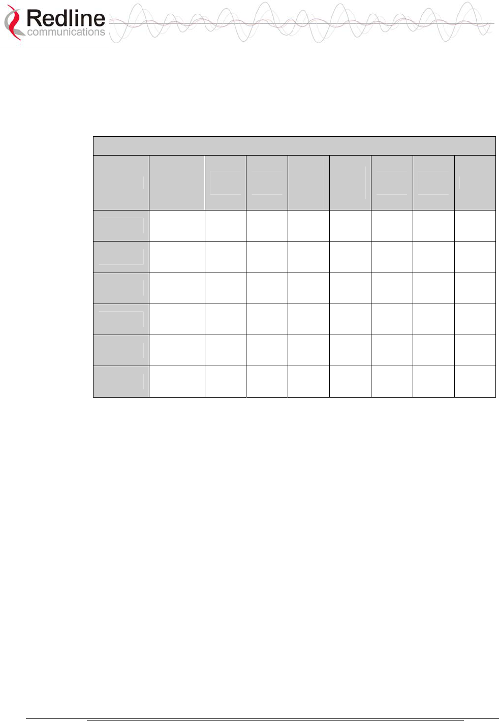
AN-50e
user manual
70-00033-02 Proprietary Redline Communications © 2004 November 2004
Page 86 of 96
8.3.5 PTP Antenna Specifications
The system is FCC certified for the directional and parabolic antennas listed in the
following tables.
Table 32: PTP Antenna Specifications
PN Polarization Freq
GHz
Gain
dBi
Beam
Width
Degree
@
-3 dB
F/B
Ratio
dB
VSWR
R.L.
Size
cm Kg
48-00006 Vertical or
Horizontal
5.4
5.8
28 4.5 - 40 1.7:1 60x60 5.0
48-00020 Vertical or
Horizontal
5.4
5.8
23 9 -32 1.7:1 30x30 1.5
48-00030 Vertical or
Horizontal
5.4
5.8
22 12 - 30 1.5:1 30 6.8
48-00031 Vertical or
Horizontal
5.4
5.8
28 6.2 -36 1.5:1 60 9.9
48-00032 Vertical or
Horizontal
5.4
5.8
31.2 4.2 -38 1.5:1 90 15.8
48-00033 Vertical or
Horizontal
5.4
5.8
34.6 3.4 -42 1.5:1 120 27
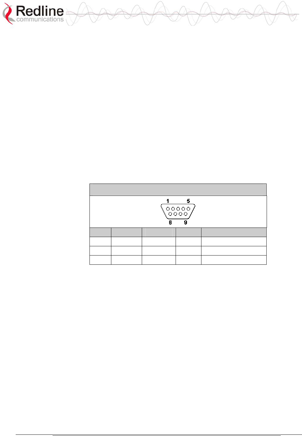
AN-50e
user manual
70-00033-02 Proprietary Redline Communications © 2004 November 2004
Page 87 of 96
8.4 CLI Interface
8.4.1 Console (RS-232) Port
All operator communications with the terminal may be made using a direct
connection to the serial Console Port on the back of the terminal. This section
describes the procedures for configuring and operating the terminal via the
Console Port using the command line interface (CLI).
Connect a PC/Terminal to the terminal's serial port DB9 connector using a cross-
connect or null modem cable (DB9 female-female). Set the PC/Terminal to
emulate a VT-52 or VT-100 terminal, using the following port settings: Bits Per
Second: 9600; Data Bits: 8; Parity: None; Stop Bits: 1; Flow Control: Hardware
The following table lists the terminal 9 PIN D-SUB male connector pinout.
Table 33: Console (RS-232) Port Pinout
Pin Name RS232 V.24 Description
2 RXD BB 104 Receive Data
3 TXD BA 103 Transmit Data
5 GND AB 102 System Ground
V.24 column is ITU-TSS V.24 circuit name.
RS232 column is RS232 circuit name.
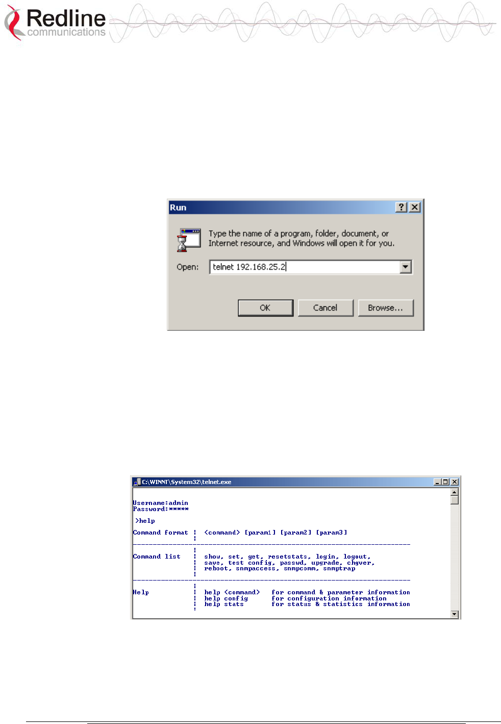
AN-50e
user manual
70-00033-02 Proprietary Redline Communications © 2004 November 2004
Page 88 of 96
8.4.2 Connecting via Telnet
All operator communications with the terminal may be made using CLI over
Telnet. This offers the advantage of allowing the operator to access and control the
terminal remotely from any geographical location, without the need for a web
browser. This section describes the procedures for configuring and operating the
terminal via Telnet using the command line interface (CLI).
To connect to the terminal, Telnet to the IP address of the terminal (default address
shown below).
Figure 40: Connecting via Telnet
When the command prompt screen appears, login using the Username: admin and
Password: admin. The terminal may now be configured and queried using a set of
CLI commands. Type ‘help’ for a list of general commands.
8.4.3 CLI Commands
The following commands are available via Telnet and Console connections to the
terminal. For online help, type ‘help <command>’ at the command prompt.
Figure 41: CLI Help Screen
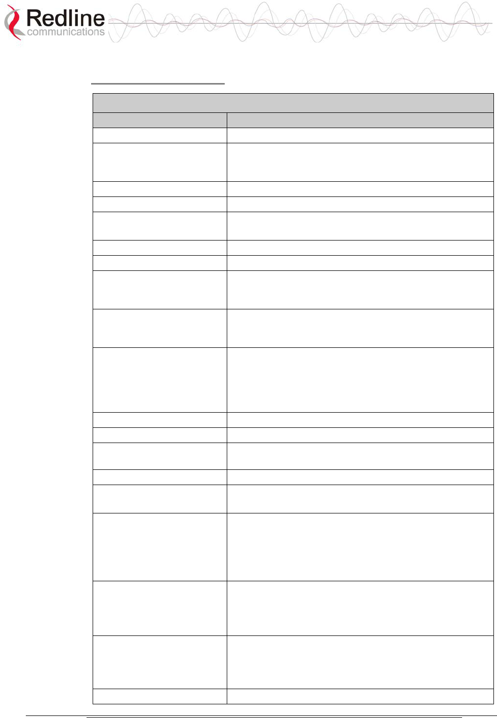
AN-50e
user manual
70-00033-02 Proprietary Redline Communications © 2004 November 2004
Page 89 of 96
General Commands
Table 34: CLI - General Commands
Command Description
chgver Swaps the operating and secondary software versions
get Get <parameter name> displays the value for a status
parameter. For configuration parameters, use Set
command.
login Allows login under a different username and password
logout Disconnects user from the terminal.
passwd Change password for user.
passwd <username> <newpassword>
reboot Reboots the terminal. Reboot <time in seconds>
resetstats Resets all statistics
save config Permanently saves system configuration settings. This
command is required to activate all Configuration
settings set previously
save snmp Permanently saves SNMP configuration settings. This
command is required to activate all SNMP settings set
previously.
set Set one configuration parameter:
<parameter name> [<value>]
Without <value>, ‘set’ returns the actual value for
configuration parameters. For status parameters, use the
Get command.
show config Returns a list of all System Configuration parameters.
show log Returns a list of current system log entries.
show snmp Returns a list of all SNMP communities and related
parameters.
show stats Returns a list of all System Status parameters.
snmpaccess Modify access rights for a community (see snmpcomm)
snmpaccess <community name> <access>
snmpcomm To add a new SNMP community:
snmpcomm add <community name> <access>
<access> can be: r,w,t or any combination
To delete an SNMP community
snmpcomm del <community name>
snmptrap To add a trap destination for an SNMP community:
snmptrap add <community name> <IP destination>
To delete a trap destination for an SNMP community:
snmptrap del <community name> <IP destination>
test config Allows testing of configuration settings for 5 minutes,
after which the system reverts to the previously saved
settings.
To make settings permanent use 'save' command.
upgrade Begin a software upload.

AN-50e
user manual
70-00033-02 Proprietary Redline Communications © 2004 November 2004
Page 90 of 96
Table 34: CLI - General Commands
Command Description
upgrade <ipaddr> <filename>
General Information
Table 35: CLI - General Information Commands
Command Description
gateway Specifies the IP address of the default router
ipaddr Specifies the IP address used by the local terminal
ipmask Specifies the IP Subnet Mask used by the local terminal
macaddr Specifies the Ethernet MAC address used by local
terminal
master Indicates whether the system is operating as the master
system.
Important: For each set of Systems, only one terminal
must be designated Master.
rflink Yes: RF link up / No: RF link down
starttime Specifies the time elapsed since the system started
swver Specifies the operating software version
sysdetails Specifies the location, telephone #, contact information,
etc.
sysname Identifies the local terminal
ubrate Indicates the system's current uncoded burst rate
System Status
Table 36: CLI - System Status
Command Description
cableattn The attenuation of the signal over the IF cable
erxpkt Number of packets successfully received locally
erxpktd Number of packet errors received locally
etxpkt Number of Ethernet packets transmitted
gateway Specifies the IP address of the default router
ipaddr Specifies the IP address used by the local terminal
ipmask Specifies the IP Subnet Mask used by the local terminal
ll Actual length of the path that the wave travels.
macaddr Specifies the Ethernet MAC address used locally
master Indicates if the system is serving as the master system.
Important: For each set of Systems, only one terminal
must be designated Master.
resetstats Resets all statistics
rffreq The center frequency of the channel in use
rflink Yes: RF link up. No: RF link down
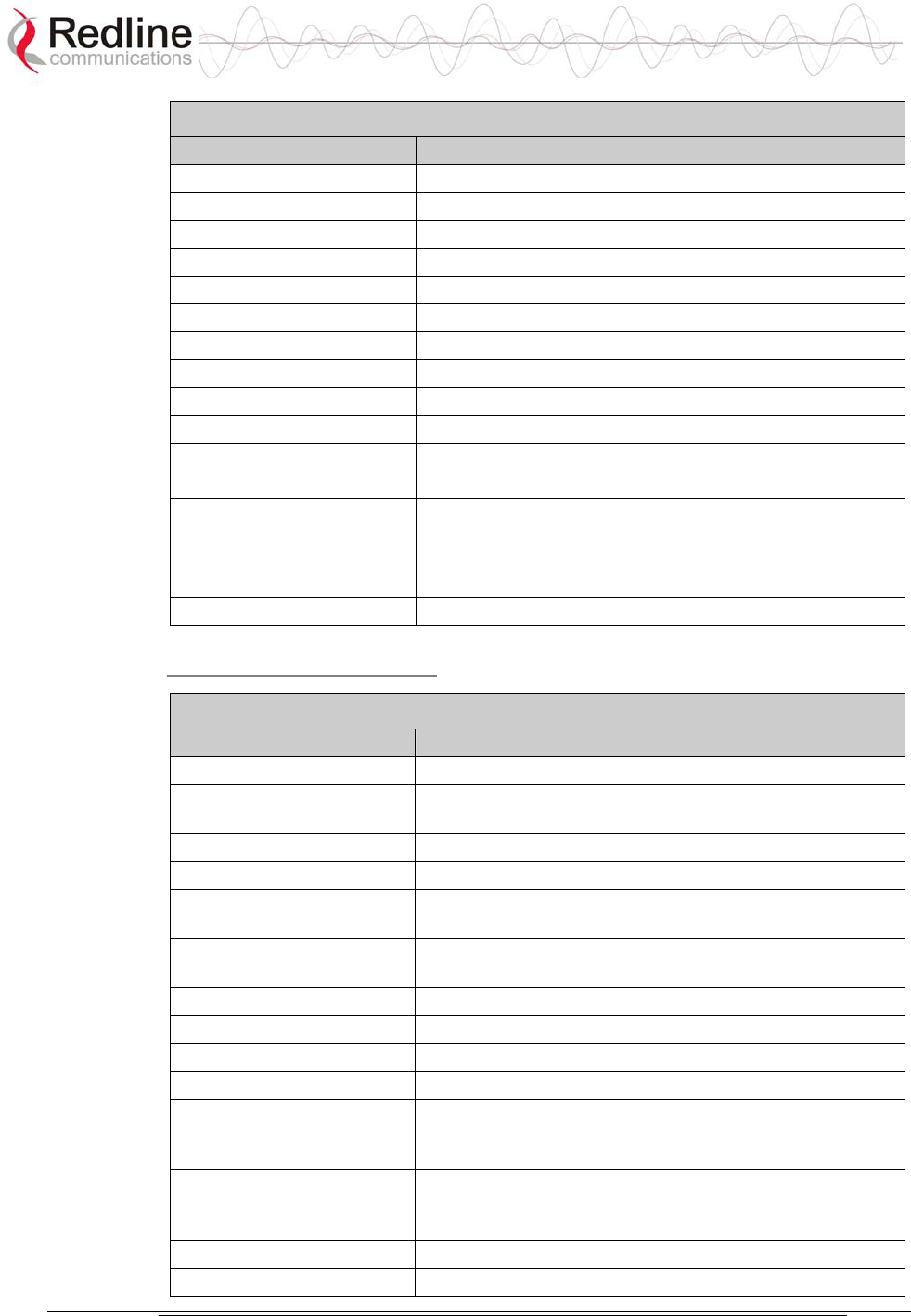
AN-50e
user manual
70-00033-02 Proprietary Redline Communications © 2004 November 2004
Page 91 of 96
Table 36: CLI - System Status
Command Description
rfstatus An error code (0-31), indicating the RF status
rssimax The maximum received signal strength
rssimean The average received signal strength
rssimin The minimum received signal strength
sinadr The no. of successful wireless pkt. received over the air
swver Specifies the operating software version
sysname Identifies the local terminal
txpower The actual current transmit power level
ubrate Indicates the system's current uncoded burst rate
wrxpkt The no. of successful wireless pkt. received over the air
wrxpktd The no. of wireless pkt. received with errors over the air
wrxpktr The no. of wireless pkt. retransmitted over the air
wtxpkt The no. of wireless pkt. successfully transmitted over the
air
wtxptd The no. of transmitted pkt. discarded by the remote-end
terminal
wtxpktr The no. of wireless pkt. retransmitted over the air
System Configuration
Table 37: CLI - System Configuration
Command Description
adaptmod Enables Adaptive Modulation mode.
buzzer Specifies whether the antenna buzzer is enabled -
defaults to voltage.
chgver Change the operating software version
encrypt Specifies whether over-the-air data encryption is enabled
encryptkey Enter the remote-end terminal's MAC address if
encryption is enabled
flowctrl Specifies whether flow control on the Ethernet port is
enabled
gateway Specifies the IP address of the default router
http Specifies whether configuration over HTTP is enabled
ipaddr Specifies the IP address used by the local terminal
ipmask Specifies the IP Subnet Mask used by the local terminal
llmod Specifies if the link length is calculated automatically or
manually. Available options: off for auto and on for
manual.
llmu Specifies the current measurements units used for the
link length. Available options: off for miles and on for
kilometers.
ll Actual length of the path that the wave travels.
macaddr Specifies the Ethernet MAC address used by the local
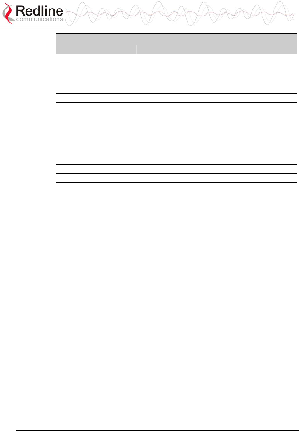
AN-50e
user manual
70-00033-02 Proprietary Redline Communications © 2004 November 2004
Page 92 of 96
Table 37: CLI - System Configuration
Command Description
terminal
master Indicates whether the system is operating as the master
system.
Important: For each set of Systems, only one terminal
must be designated Master.
modreduct Used when 'AdaptMod' is disabled.
radio Specifies whether radio transmission is enabled
reboot Reset all statistics and reboot the terminal
rfchannel Available channel options: 1, 1A, 2, 2A, 3, 3A, 4, 4A, 5.
save config Permanently saves configuration settings
snmp Specifies whether configuration over SNMP is enabled
sysdetails Specifies the location, telephone #, contact information,
etc.
sysname Identifies the local terminal
telnet Specifies whether configuration over telnet is enabled
telnetport Specifies the TCP port used for telnet
test config Allows testing of these settings for 5 minutes, after which
the system reverts to the previously saved settings. Use
'Save' to make settings permanent .
txpower Specifies the max. power level of the system
ubrate Sets the desired burst rate for the link.

AN-50e
user manual
70-00033-02 Proprietary Redline Communications © 2004 November 2004
Page 93 of 96
8.5 Glossary Of Terms
Table 38: Glossary of Terms
Term Definition
Antenna Gain The measure of antenna performance relative to a theoretical antenna
called an isotropic antenna.
ARQ Automatic Repeat Request. This is the protocol used over the air for
error correction.
ATPC Automatic Transmission Power Control. The link master-end system
automatically adjusts the Tx level of remote-end system to match a
target RSSI value.
Beamwidth The angle of signal coverage provided by an antenna.
BFW Broadband Fixed Wireless
Bps Bits Per Second
A unit of measurement for the rate at which data is transmitted.
BPSK Binary Phase Shift Keying.
Channel A communications path wide enough to permit a single RF
transmission.
dB A ratio expressed in decibels.
dBi A ratio, measured in decibels, of the effective gain of an antenna
compared to an isotropic antenna.
dBm Decibels above a milliwatt
DFS Dynamic Frequency Selection (DFS) can detect interference from
other devices using the same frequency (especially radar) and
automatically take a pre-selected action such as disable transmission
or relocate transmission to alternative frequency.
DHCP Dynamic Host Configuration Protocol. A DHCP server will
automatically issue IP addresses within a specified range to devices
on a network.
Directional
Antenna
An antenna that concentrates transmission power into one direction.
Encryption For the purposes of privacy, the transformation of data into an
unreadable format until reformatted with a decryption key.
Ethernet A LAN architecture using a bus or star topology
FD Full Duplex. Refers to the transmission of data in two directions
simultaneously (i.e. a telephone)
FWA Fixed Wireless Access
Gain The ratio of the output amplitude of a signal to the input amplitude of a
signal. Typically expressed in decibels (dB).
Gateway A network point that acts as an entrance to another network.
GHz Gigahertz. 1,000,000,000 Hz, or 1,000 MHz
GUI Graphical User Interface
IF Intermediate Frequency.
IP Internet Protocol. See TCP/IP.
Isotropic A theoretic construct of an antenna that radiates its signal 360

AN-50e
user manual
70-00033-02 Proprietary Redline Communications © 2004 November 2004
Page 94 of 96
Table 38: Glossary of Terms
Term Definition
degrees both vertically and horizontally—a perfect sphere. Generally
used as a reference.
IXC Inter-exchange Carrier. A long-distance phone company.
LEC Local Exchange Carriers. The traditional local wired phone company.
LED Light Emitting Diode
LOS Line Of Sight. A clear direct path between two antennas, with no
obstructions within the first Fresnel zone.
MAC Media Access Control. A unique number assigned to a network
device. Corresponds to ISO Network Model Layer 2 data link layer.
MHz Megahertz. 1,000,000 Hz
Modem MOdulator/DEModulator. A hardware device that converts digital data
into analog and vice versa.
Modulation Any of several techniques for combining user information with a
transmitter carrier signal.
Multipath The radio echoes created as a radio signal bounces off objects.
NVRAM Non-volatile RAM. System parameters are stored in NVRAM. This
data is not affected by powering off the system.
NLOS Non Line Of Sight. Completely obstructed path between two
antennas.
OFDM Orthogonal Frequency Division Multiplexing. OFDM spreads data to
be transmitted over a large number of orthogonal carriers.
OLOS Optical Line Of Sight. A clear direct path between two antennas, with
obstructions within the first Fresnel zone.
Packet A bundle of data organized in a specific way for transmission. The
three principal elements of a packet include the header, the text, and
the trailer (error detection and correction bits).
PHY Physical Layer. Provides for the transmission of data through a
communications channel by defining the electrical, mechanical, and
procedural specifications.
PMP Point to Multipoint
PTP Point to Point
QAM Quadrature Amplitude Modulation
QPSK Quadrature Phase Shift Keying
Receiver
Sensitivity
A measurement of the weakest signal a receiver can receive and still
correctly translate it into data.
RF Radio Frequency
Rx Receiver
S/N Signal to Noise Ratio
SINADR Signal to noise and distortion ratio.
TCP/IP Transmission Control Protocol/Internet Protocol
The standard set of protocols used by the Internet for transferring
information between computers, handsets, and other devices.
TFTP Trivial File Transfer Protocol
Tx Transmitter

AN-50e
user manual
70-00033-02 Proprietary Redline Communications © 2004 November 2004
Page 95 of 96

70-00033-02 Proprietary Redline Communications © 2004 November 2004
Page 96 of 96
302 Town Centre • Suite 100 • Markham, Ontario • Canada • L3R 0E8
www.redlinecommunications.com