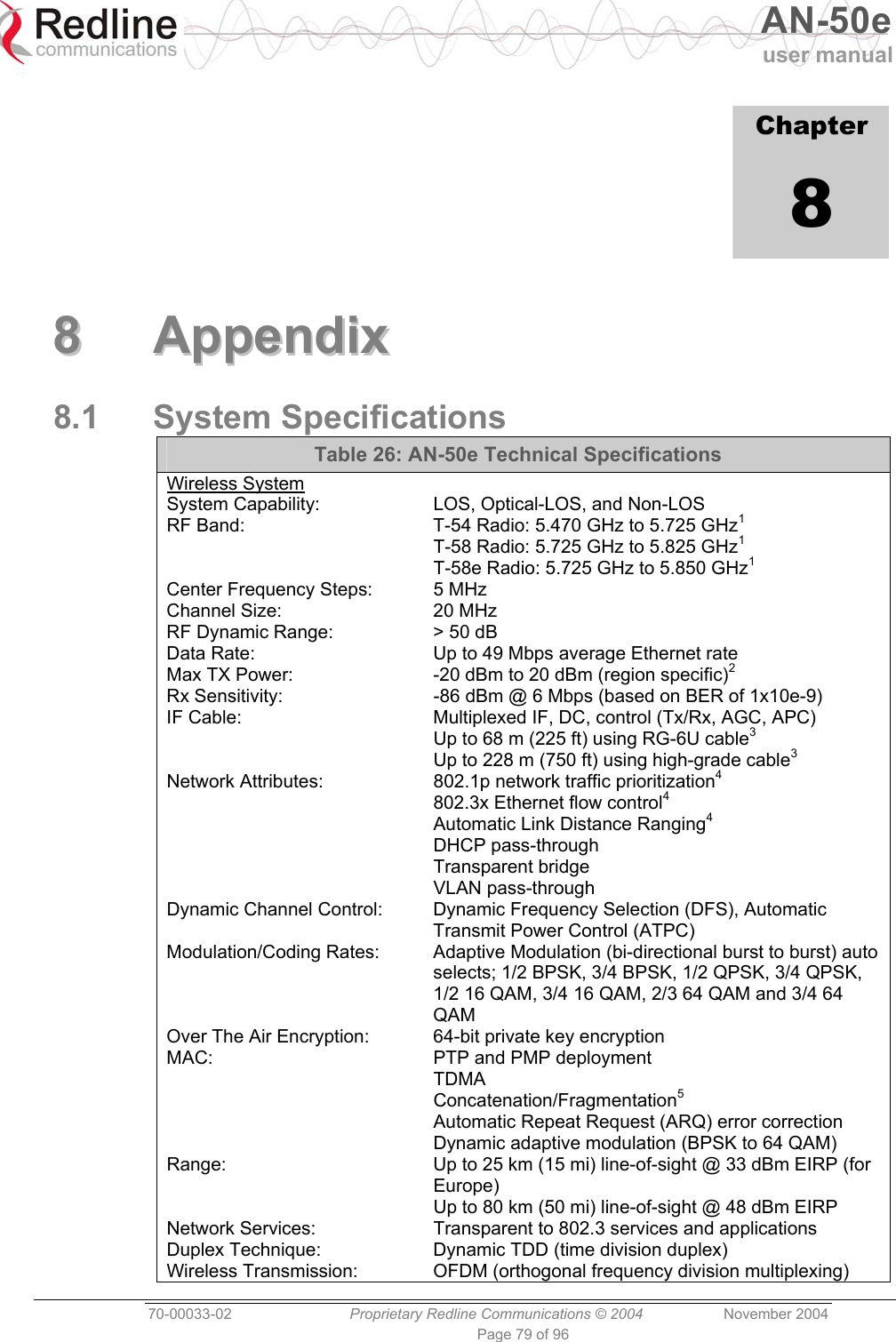
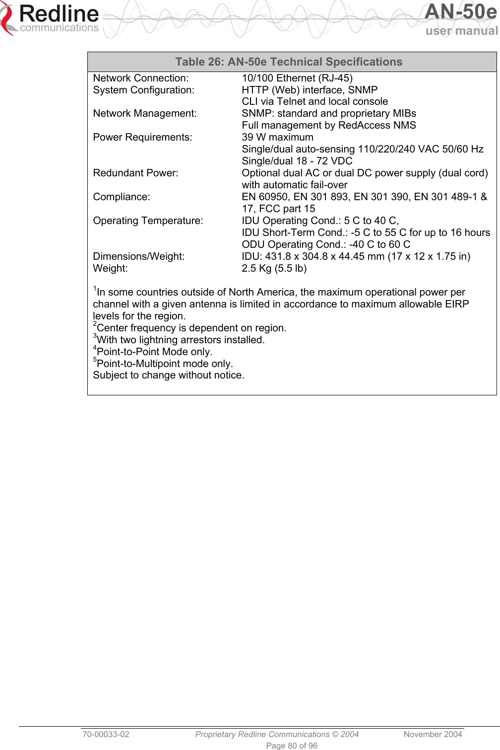
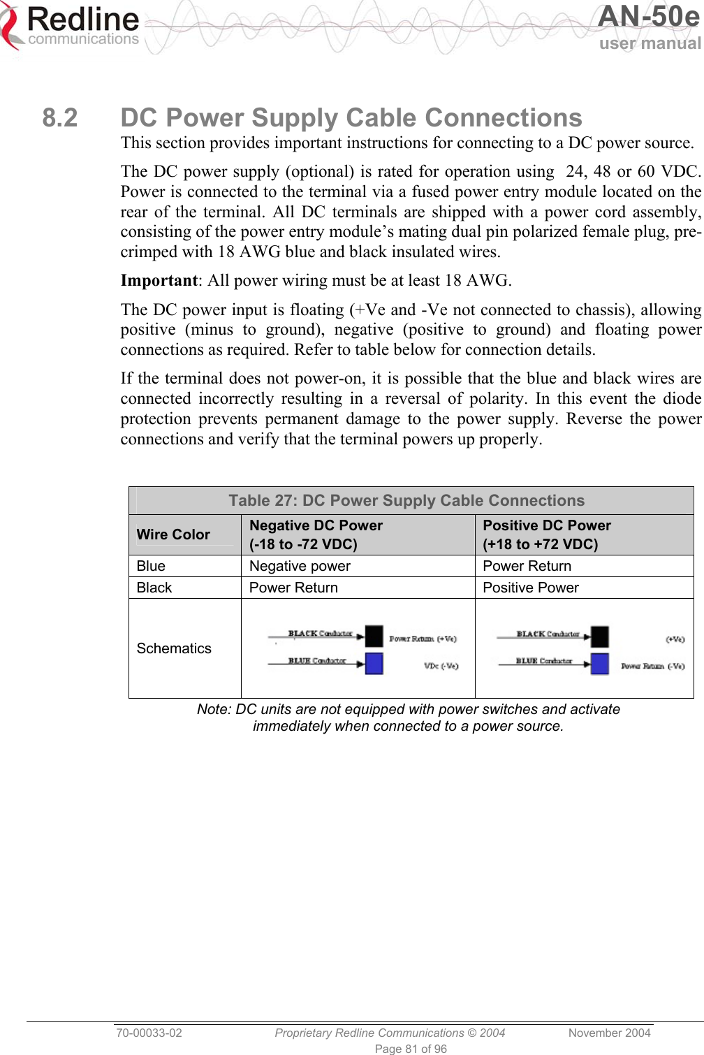
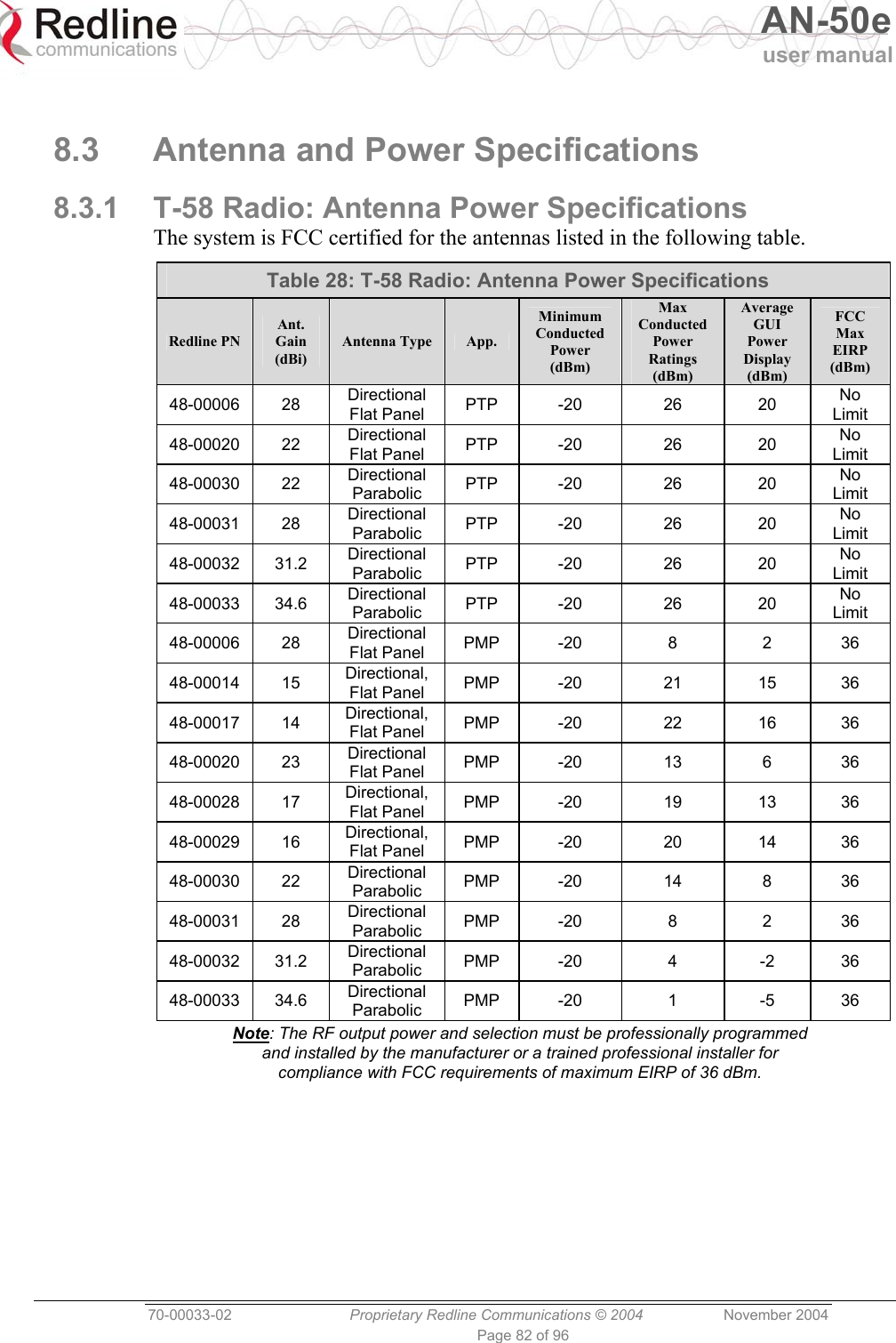
Redline Communications AN5030EX AN-50e/AN-30e System w/ T-58e Radio User Manual 70 00033 02
Redline Communications Inc. AN-50e/AN-30e System w/ T-58e Radio 70 00033 02
UserManual.wiki
>
Redline Communications
>
AN5030EX User Manual
>
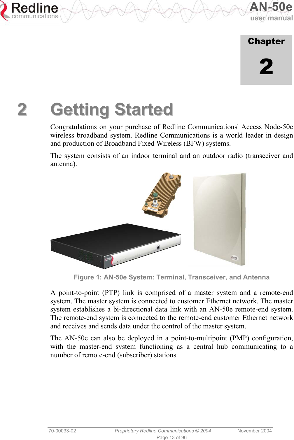
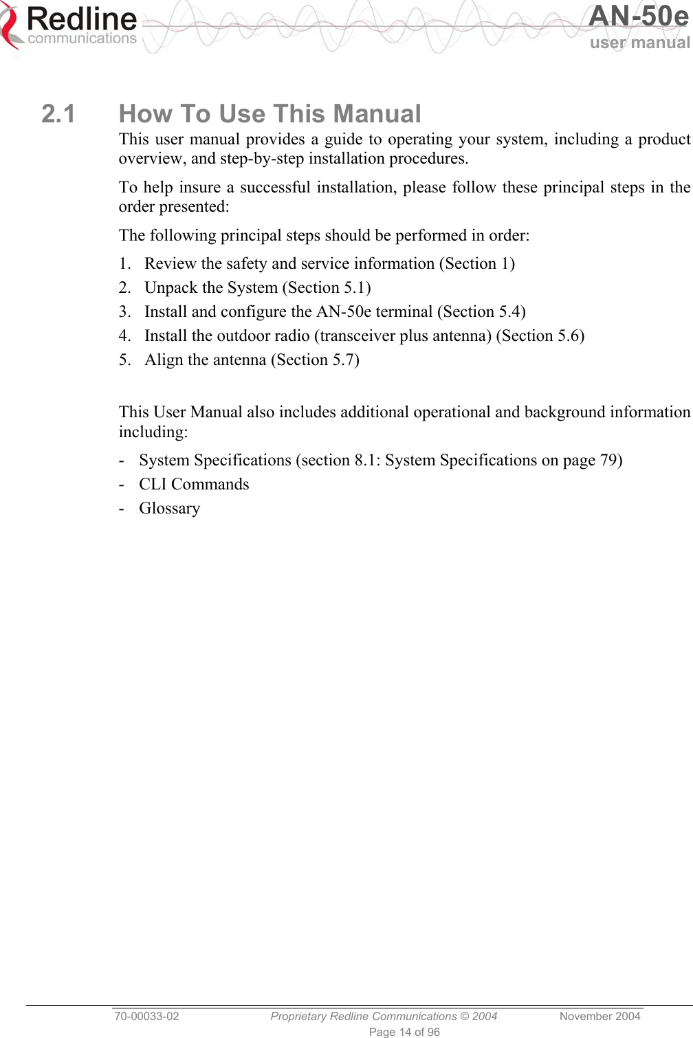
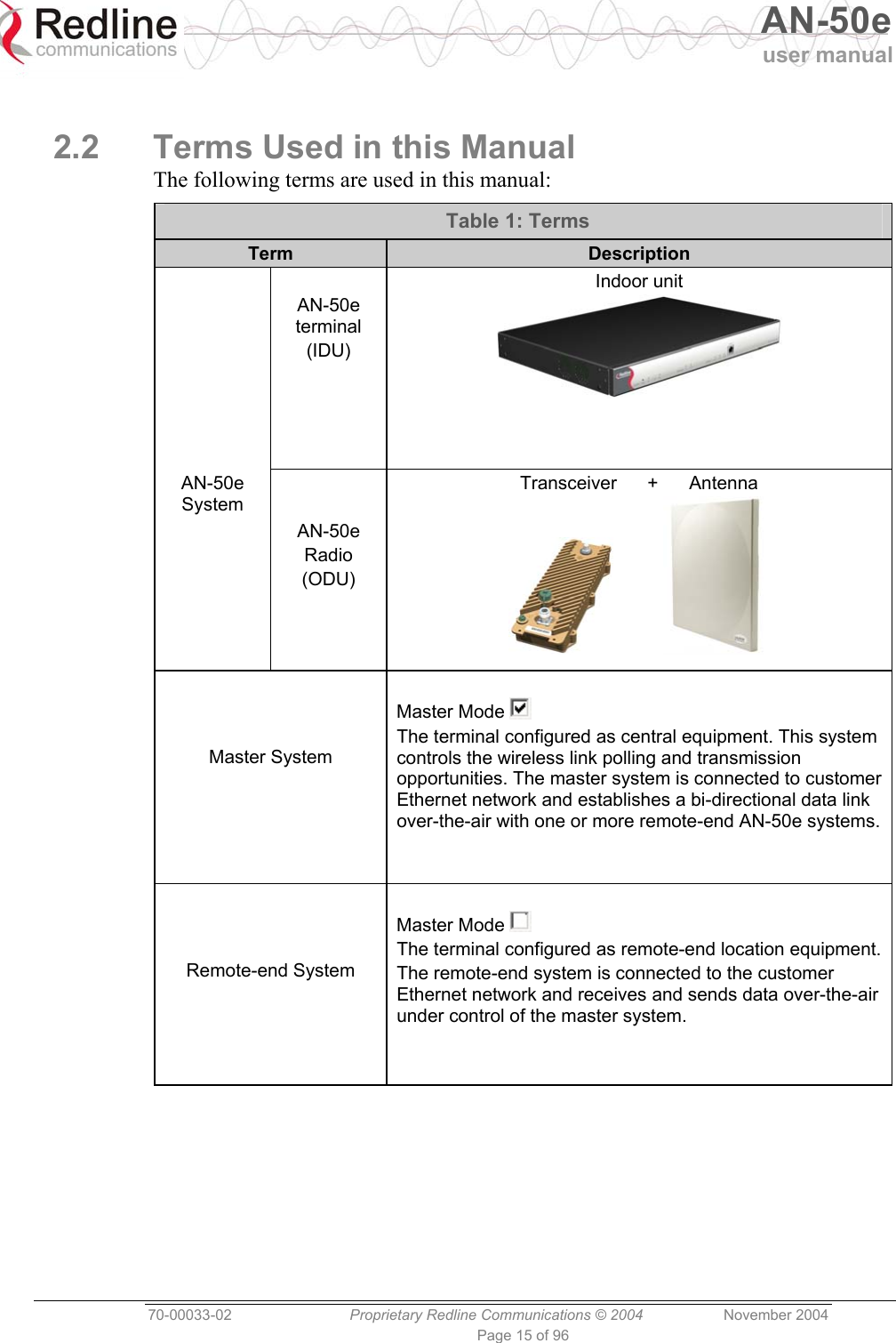
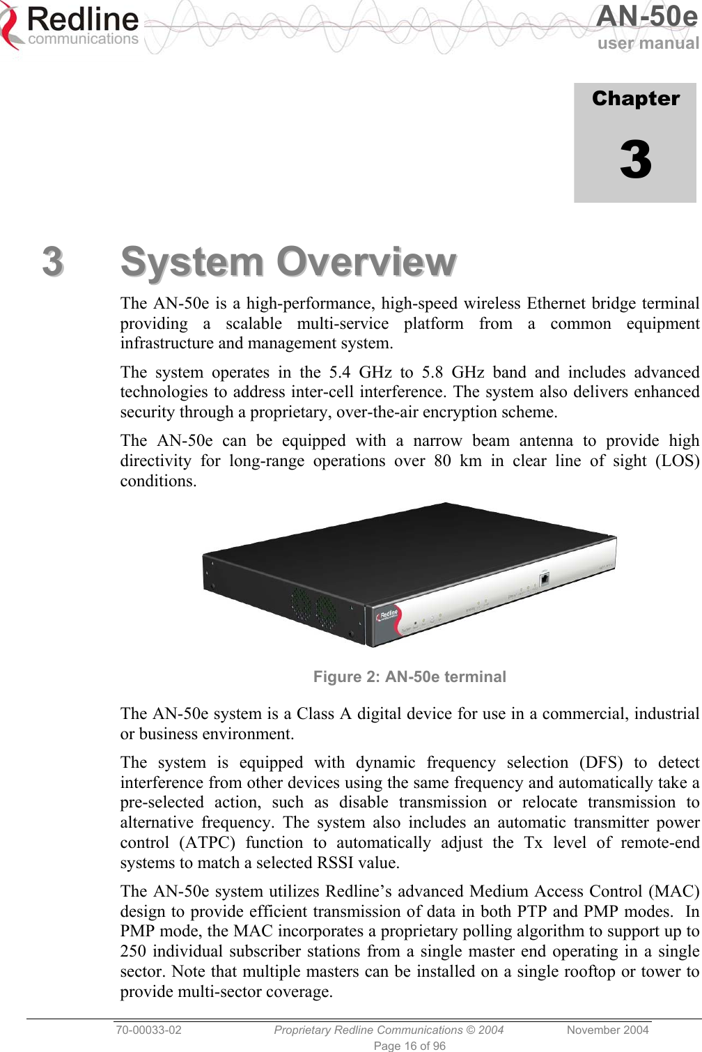
USERS MANUAL 2
Contents
1.
USERS MANUAL 1
2.
USERS MANUAL 2
USERS MANUAL 2
Navigation menu
Upload a User Manual
Namespaces
Wiki Guide
HTML
PDF
Info
Views
User Manual
Discussion / Help
Navigation


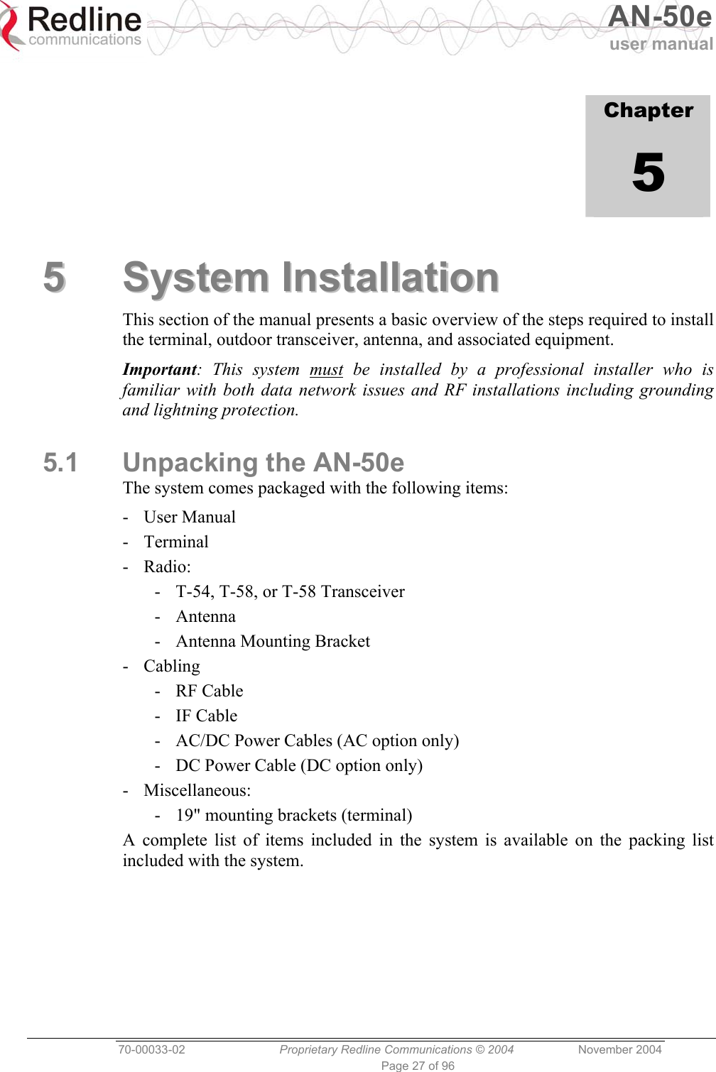
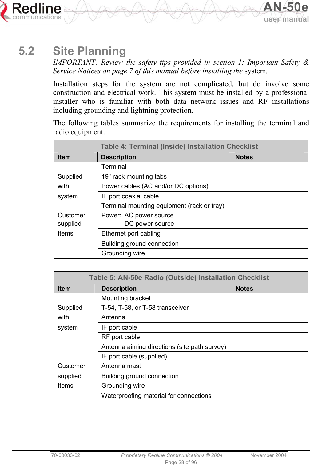
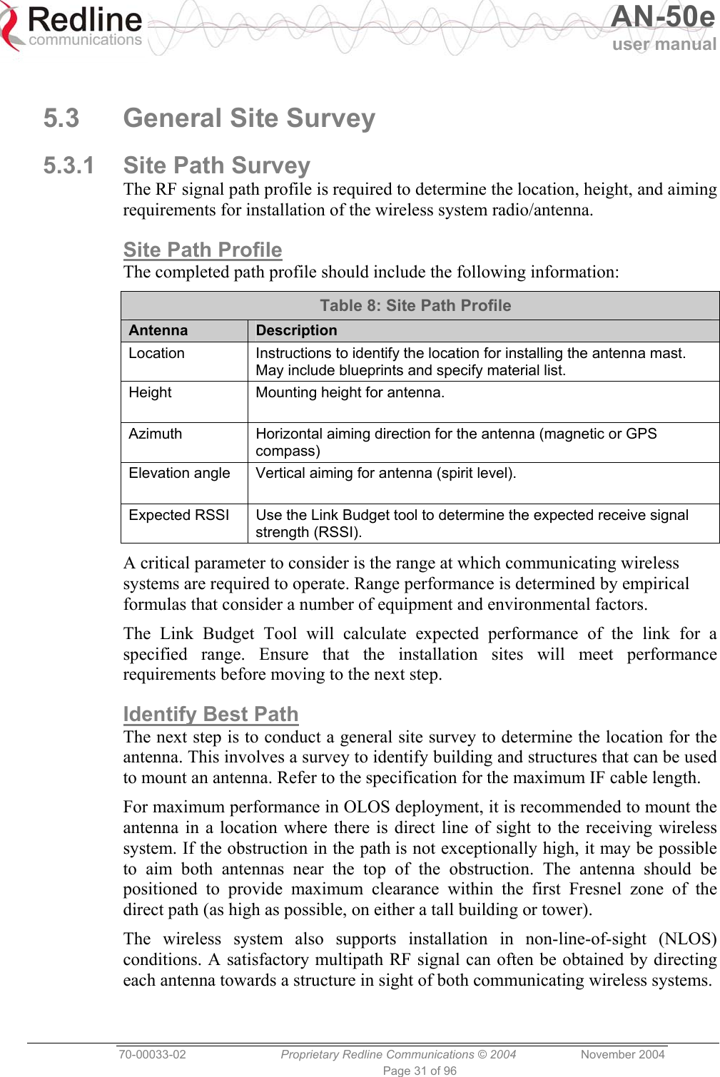
![AN-50e user manual 70-00033-02 Proprietary Redline Communications © 2004 November 2004 Page 29 of 96 5.2.1 Master System Settings The following table lists the master system parameters must be set prior to operation of the wireless portion of the system. Refer to section 6.3: System Configuration Screens on page 49 for additional details of these fields. Table 6: Required Configuration Settings - Master System Item Description Ethernet IP address Network address of the AN-50e master system (must be unique). IP Subnet Mask Network subnet mask. Default Gateway Address Default router/gateway on the local Ethernet segment. Ethernet Mode Select the operating mode of the Ethernet port (auto-negotiate, 10/100 Mbps). Wireless Master Mode Check this box to enable the System to operate as the master system. Only one terminal must be designated master. RF Freq. [MHz] Enter the channel center frequency of the system. TX Power [dBm] Enter the default transmit power level (dBm). Refer to section 8.3: Antenna and Power Specifications on page 82. DFS Action Select the mode of operation for DFS on this terminal. If the DFS function is required by local regulations, then DFS will be set on and this selection will be disabled. DFS Antenna Gain Enter the antenna gain (dBm). This value must be set to match the system antenna. ATPC Enable Check this box to enable the Automatic Transmit Power Control function. Adaptive Modulation Check this box to enable adaptive modulation mode. Radio Enable Check this box to enable the radio transmitter.](https://usermanual.wiki/Redline-Communications/AN5030EX.USERS-MANUAL-2/User-Guide-492957-Page-29.png)
![AN-50e user manual 70-00033-02 Proprietary Redline Communications © 2004 November 2004 Page 30 of 96 5.2.2 Remote-end System Settings The following remote-end system parameters must be set prior to operation of the wireless portion of the system. Refer to section 6.3: System Configuration Screens on page 49 for additional details of these fields. Table 7: Required Configuration Settings - Remote-end system Item Description Ethernet IP address Network address of the AN-50e remote-end system (must be unique). IP Subnet Mask Network subnet mask. Default Gateway Default router/gateway on the local Ethernet segment. Ethernet Mode Select the operating mode of the Ethernet port (auto-negotiate, 10/100 Mbps). Wireless Master Mode Ensure that the Master Mode check box is not checked ( ). RF Freq. [MHz] Enter the channel center frequency of the system. TX Power [dBm] Enter the default transmit power level (dBm). Refer to section 8.3: Antenna and Power Specifications on page 82. If the TX power levels are restricted by local regulations, the maximum Tx power available will be limited to this value. Auto Scan Check this box to enable the remote-end System to automatically scan for the frequency of the AN-50e Master (system with Master Mode setting enabled). DFS Action Select the mode of operation for dynamic frequency selection (DFS). If the DFS function is required by local regulations, then DFS will be set on and this selection will be disabled. DFS Antenna Gain Enter the antenna gain (dBm). This value must be set to match the System antenna. ATPC Enable Check this box to enable the Automatic Transmit Power Control function. Adaptive Modulation Check this box to enable adaptive modulation mode. Radio Enable Check this box to enable the radio transmitter.](https://usermanual.wiki/Redline-Communications/AN5030EX.USERS-MANUAL-2/User-Guide-492957-Page-30.png)
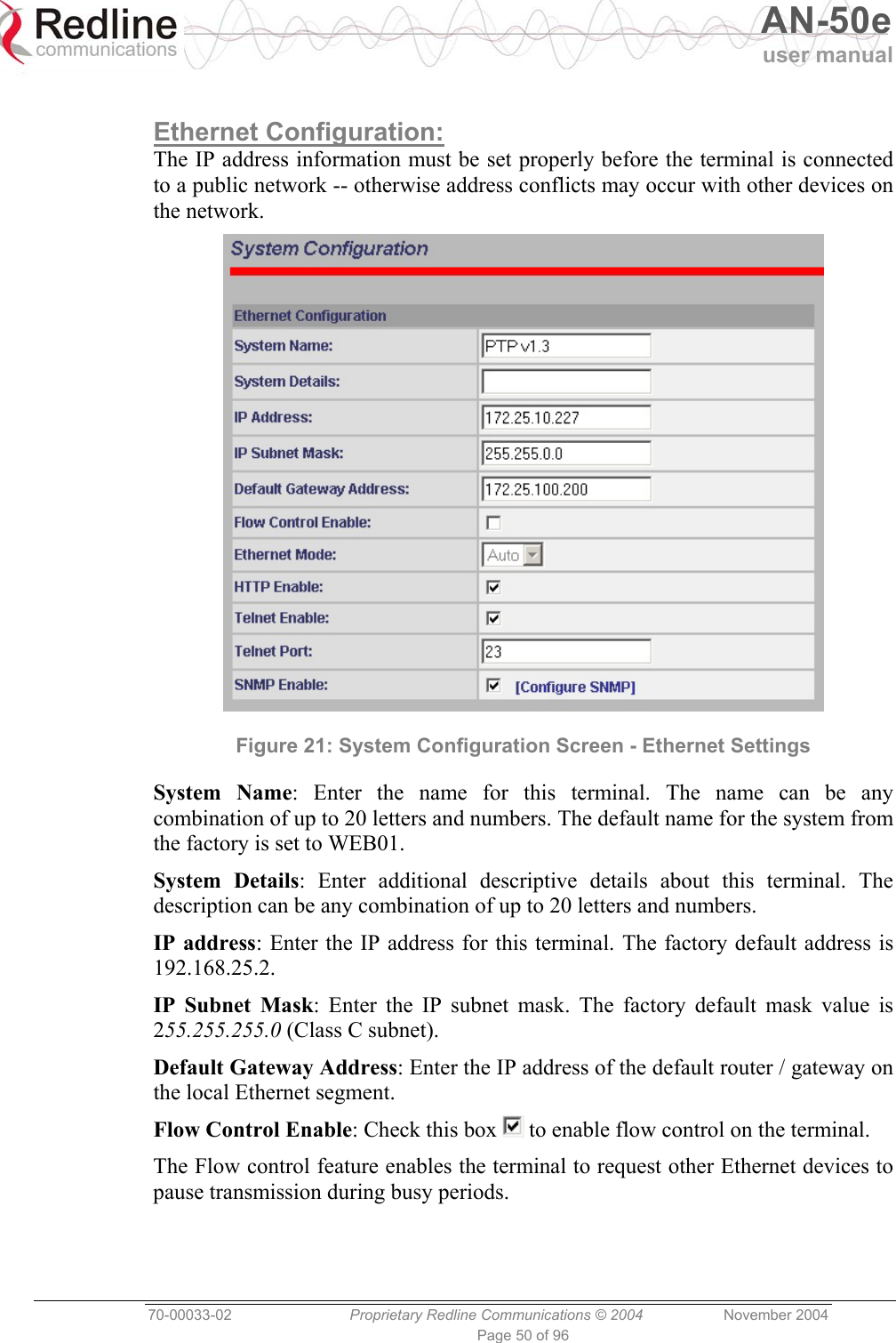
![AN-50e user manual 70-00033-02 Proprietary Redline Communications © 2004 November 2004 Page 36 of 96 The following sections list parameters that must be set before the terminal is connected to the Ethernet port, or the IF cable is connected to the transceiver. 5.5.2 Ethernet Settings The network address settings for the every terminal must be configured before the terminal can be connected to the local area network. Only the following Ethernet settings need to be adjusted at this time: IP address: Enter the IP address for this terminal. Each System must also have a unique IP address. IP Subnet Mask: Enter the IP subnet mask. Default Gateway Address: Enter the IP address of the default router or gateway on the local Ethernet segment. Ethernet Mode: Select the operating mode of the Ethernet port (auto-negotiate, 10Base-T, or 100Base-T). 5.5.3 Wireless Settings The wireless parameters must be set properly before the terminal is enabled to transmit -- otherwise it may cause interference to other high frequency devices operating in the vicinity. See section 6.3.1: Configure System on page 49 for more details. Master System Settings (Master Mode ) The following settings should be set for the system operating as master: Master Mode: Check this box to enable this system to operate as the master system. Only one terminal must be designated Master. RF Freq. [MHz]: Enter the channel center frequency of the system. TX Power [dBm]: Enter the default tx power level (dBm). Refer to section 8.3: Antenna and Power Specifications on page 82. DFS Action: Select the mode of operation for DFS on this terminal. Important: Where specified by local regulations, the DFS feature will always be enabled. The default selection will be Chg Freq. DFS Antenna Gain: Enter the antenna gain (dBm). This value must be set to match the system antenna. ATPC Enable: Check this box to enable the Automatic Transmit Power Control function. This feature will automatically adjust the power level of the remote-end system. Adaptive Modulation: Check this box to enable adaptive modulation mode. Radio Enable: Check this to enable the radio transmitter.](https://usermanual.wiki/Redline-Communications/AN5030EX.USERS-MANUAL-2/User-Guide-492957-Page-36.png)
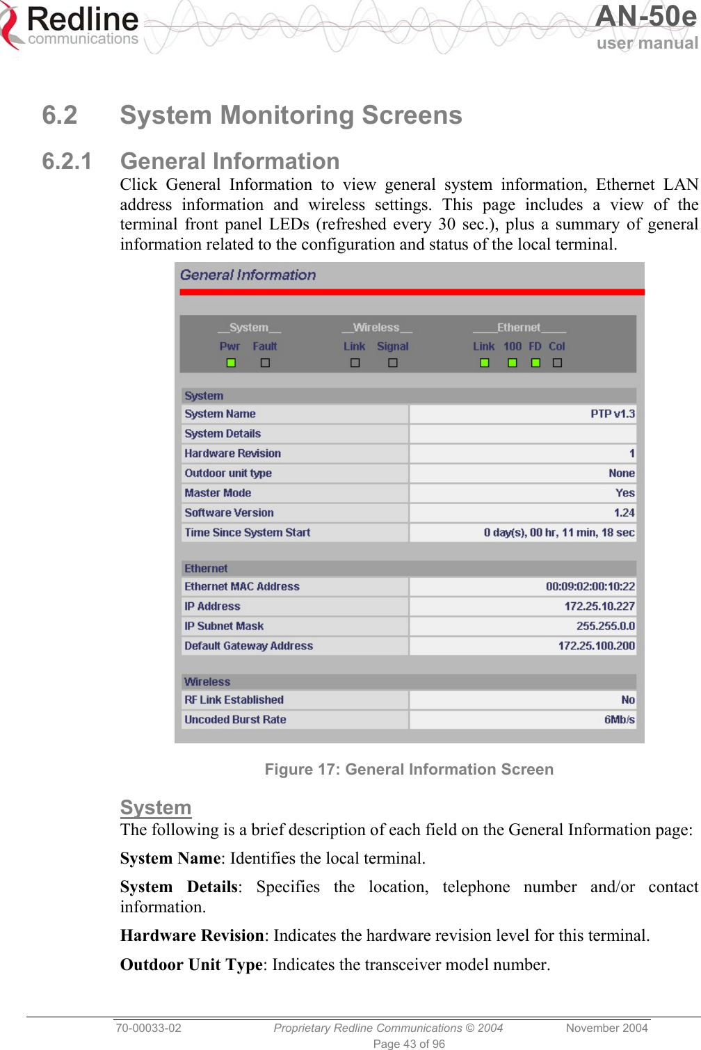
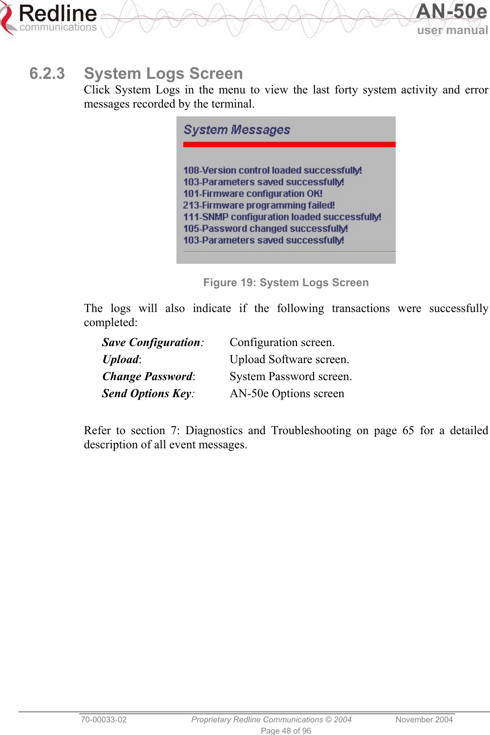
![AN-50e user manual 70-00033-02 Proprietary Redline Communications © 2004 November 2004 Page 44 of 96 Master Mode: Indicates if the system is operating as the master system. Yes: Master system. No: Remote-end system. Software Version: Specifies the software version in use. Time Since System Start: Specifies the time [dd/hh/mm/ss] since the system started. Ethernet: Ethernet MAC Address: Hardware address of terminal. IP Address: IP address of the terminal. IP Subnet Mask: Subnet for the IP address. Default Gateway Address: IP address of the default router/gateway on the local Ethernet segment. Wireless: RF Link Established: Status for the wireless link connection. Yes - RF link has been successfully established with the remote-end terminal. No - RF link has not been established with the remote-end terminal. Uncoded Burst Rate [Mb/s]: The actual current uncoded burst rate for the link.](https://usermanual.wiki/Redline-Communications/AN5030EX.USERS-MANUAL-2/User-Guide-492957-Page-44.png)
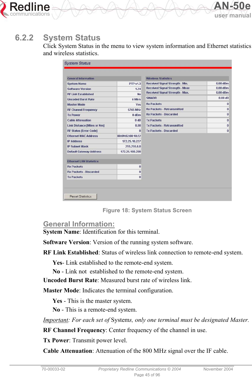
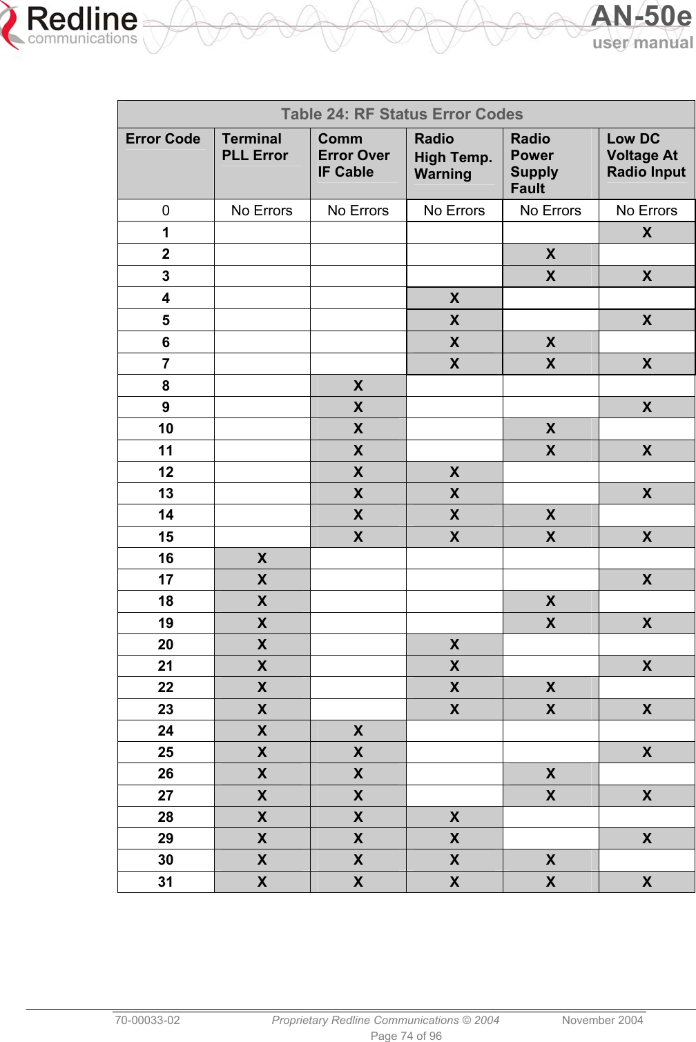
![AN-50e user manual 70-00033-02 Proprietary Redline Communications © 2004 November 2004 Page 46 of 96 Link Distance [Miles or Km]: Distance between systems. RF Status [Error Code]: An error code indicating the condition of the system RF components. See the RF Status Error Code Table 24: RF Status Error Codes on page 74 for details. Code zero is normal. Ethernet MAC Address: MAC address of this terminal. IP address: IP address for the this terminal IP Subnet Mask: IP subnet mask. Default Gateway Address: IP address of the default router / gateway. Ethernet LAN Statistics: Rx packets: Number of non-errored packets received. Rx packets - Discarded: Number of errored packets received. Tx Packets: Number of Ethernet packets transmitted. Wireless Statistics: Received Signal Strength: Min: Minimum RSSI measured since the last screen refresh. Received Signal Strength: Mean: Average RSSI measured since the last screen refresh. Received Signal Strength: Max: Maximum RSSI measured since the last screen refresh. SINADR: Average signal to interference, noise and distortion ratio measured since the last screen refresh. The ratio is based on the digital information provided from the output of the A/D converter, and includes the effects of the AGC. Rx Packets: Number of wireless packets received over the air from the remote-end terminal. Rx Packets: Retransmitted: Number of wireless packets retransmitted from the remote-end terminal. Rx Packets: Discarded: Number of wireless packets originating from the remote-end terminal received over the air with errors due to degradation in the RF link. Tx Packets: Number of wireless packets (including Ethernet frames and error correction bytes) successfully transmitted over the air by the local terminal. Tx Packets: Retransmitted: Number of wireless packets retransmitted over the air by the local terminal. The retransmission scheme is based on the Automatic Repeat Request (ARQ) algorithm that detects when packets are lost, and makes a request to the MAC scheduler to repeat transmission of the lost packets. Tx Packets: Discarded: Total number of transmitted wireless packets discarded by the remote-end terminal, due to degradation in the RF link.](https://usermanual.wiki/Redline-Communications/AN5030EX.USERS-MANUAL-2/User-Guide-492957-Page-46.png)
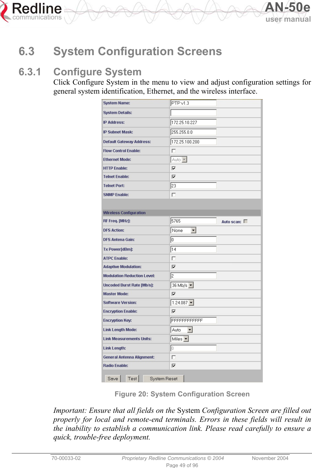
![AN-50e user manual 70-00033-02 Proprietary Redline Communications © 2004 November 2004 Page 52 of 96 Wireless Configuration: The wireless parameters must be set properly before the terminal is allowed to transmit using the radio -- otherwise it may cause interference to other high frequency devices operating in the vicinity. Refer to section 5.5: Configure Essential System Parameters on page 34 for information about parameters that must be set before operating the wireless portion of the system. Figure 22: System Configuration Screen - Wireless Settings RF Freq. [MHz]: Enter the channel center frequency of the system. The table below specifies the center frequencies of each permitted channel. To avoid interference, the channel frequencies of two links operating within close proximity must be separated by 20 MHz or more. Note: Availability of frequency bands listed in the following tables is based on the factory entered option key. Refer to the tables on the following page.](https://usermanual.wiki/Redline-Communications/AN5030EX.USERS-MANUAL-2/User-Guide-492957-Page-52.png)
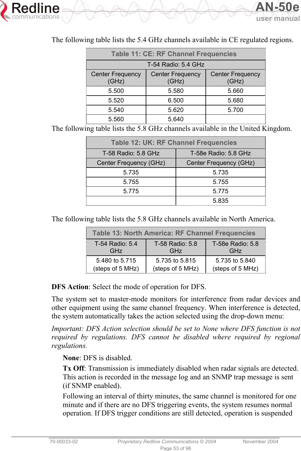
![AN-50e user manual 70-00033-02 Proprietary Redline Communications © 2004 November 2004 Page 54 of 96 for an additional thirty minutes. This cycle continues until no DFS trigger events are detected or the operator manually reconfigures the system. Chg Freq: Relocate transmission to alternative frequency immediately when radar signals are detected. This action is recorded in the message log and a trap message is sent (if SNMP enabled). The new channel is selected based on allowable frequencies for the regulatory region of that installation. The channel is monitored for one minute before the system is allowed to transmit. If DFS triggering events are detected, the next available channel is selected and monitored. The system is not allowed to return to a channel on which DFS trigger events were detected for a period of thirty minutes. If DFS trigger events are detected on all channels the system suspends operation until the thirty-minute time interval expires for at least one channel. DFS Antenna Gain: Enter the gain (dBm) for the system antenna. It is important that this value is set to correctly match the antenna gain. If the antenna gain is set higher than the actual antenna gain, the DFS is less sensitive to detecting interference, and the system is not operating in compliance with the UK/ETSI standard. If the antenna gain is set lower than the actual antenna gain, the DFS is more sensitive to detecting interference and may cause false triggers. Important: The DFS Antenna Gain must be set when DFS is required by regional regulations. TX Power [dBm]: Enter the default tx power level (dBm). Refer to section 8.3: Antenna and Power Specifications on page 82 lists the maximum transmit power setting based on the antenna gain for a series of frequency settings. Note: In some countries outside of North America, the maximum operational power per channel for a specific antenna is limited in accordance to maximum allowable EIRP levels for the region. Table 14: Max. Operational Power Per Channel (in dBm) vs. Modulation lists the maximum transmit power levels for each modulation setting. Restrictions exist when operating at data rates above 24 Mb/s. Table 14: Max. Operational Power Per Channel (in dBm) vs. Modulation 64QAM ¾ (54 Mb/s) 64QAM ⅔(48 Mb/s)16QAM ¾(36 Mb/s) 16QAM ½(24 Mb/s)QPSK ¾ (18 Mb/s)QPSK ½ (12 Mb/s) BPSK ¾ (9 Mb/s) BPSK ½ (6 Mb/s) Max Tx Power 14 15 19 20 20 20 20 20 ATPC Enable: Check this box to enable the ATPC function. The master-end system will automatically adjust the Tx level of both the master-end and remote-end systems to optimize the system performance.](https://usermanual.wiki/Redline-Communications/AN5030EX.USERS-MANUAL-2/User-Guide-492957-Page-54.png)
![AN-50e user manual 70-00033-02 Proprietary Redline Communications © 2004 November 2004 Page 55 of 96 Adaptive Modulation: Check this box to enable adaptive modulation mode. It is recommended to use adaptive modulation mode when using Ethernet only traffic. When enabled, the system can automatically change the modulation scheme to the highest possible order, based on measured RF performance. Adjust the modulation scheme by setting the Uncoded Burst Rate parameter. If packet errors exceed one in one million, the system will automatically step down the modulation scheme to maintain the link. Modulation Reduction Level: This manual setting specifies how many levels the system must drop in modulation during re-transmission of erroneous wireless packets. The level can be set from 0-7, with 2 being the recommended value. Valid only when Adaptive Modulation is disabled. Uncoded Burst Rate [Mb/s]: Select the desired uncoded burst rate for the link. Master Mode: Check this box to enable the system to operate as the master system. Each link is comprised of a master system and one or more remote-end systems. The master system establishes and manages the bi-directional data link with each AN-50e remote-end system. The remote-end system receives and sends data under the control of the master system. Only one system in a wireless link must be set for Master mode. Software Version: Select the current version of the system software. The system includes sufficient memory to hold two independent software images. The operator can specify which software image is used in the system. See Upload Software Section 6.4: for additional details. Encryption Enable: Check this box to enable over-the-air encryption. If encryption is enabled, no Ethernet packets can be transferred unless encryption is enabled on both the local and remote-end terminals. Encryption Key: Enter the MAC address of the remote-end terminal as the over-the-air data encryption key. No Ethernet packets can be transferred unless the correct encryption is entered at both the local and remote-end terminals. Link Length Mode: Distance from master-end to remote-end. Auto: Distance calculated automatically by the terminal (recommended). Manual: the operator enters Link distance. Link Measurements Units: Select the units for the Link Length Mode field. Miles: Link length distance is displayed in miles. Kilometers: Link length distance is displayed in kilometers. Link Length: Enter the actual length of the path that the wave travels in order to establish the link. Only valid if Link Length Mode is set for Manual. General Antenna Alignment: Check this box to enable the antenna alignment audible tone generator in the transceiver. Radio Enable: Check this box to enable the radio transmitter.](https://usermanual.wiki/Redline-Communications/AN5030EX.USERS-MANUAL-2/User-Guide-492957-Page-55.png)

![AN-50e user manual 70-00033-02 Proprietary Redline Communications © 2004 November 2004 Page 85 of 96 8.3.4 Operational Power for T54 (FCC) The following table provides the maximum RF power settings based on the gain of the antenna. Table 31: 5.4 GHz -- Antenna Gain vs Max. Op. Power Ant. Gain [dBi] Max. Power [dBm] Ant. Gain [dBi] Max. Power [dBm] 6.0 15 21.0 -1 6.5 15 21.5 -1 7.0 14 22.0 -2 7.5 14 22.5 -2 8.0 13 23.0 -3 8.5 13 23.5 -3 9.0 12 24.0 -4 9.5 12 24.5 -4 10.0 11 25.0 -5 10.5 11 25.5 -5 11.0 10 26.0 -6 11.5 10 26.5 -6 12.0 9 27.0 -7 12.5 9 27.5 -7 13.0 8 28.0 -8 13.5 8 28.5 -8 14.0 7 29.0 -9 14.5 7 29.5 -9 15.0 5 30.0 -9 15.5 5 30.5 -10 16.0 4 31.0 -10 16.5 4 31.5 -11 17.0 3 32.0 -11 17.5 3 32.5 -12 18.0 2 33.0 -12 18.5 2 33.5 -13 19.0 1 34.0 -13 19.5 1 34.5 -14 20.0 0 35.0 -14 20.5 0](https://usermanual.wiki/Redline-Communications/AN5030EX.USERS-MANUAL-2/User-Guide-492957-Page-85.png)
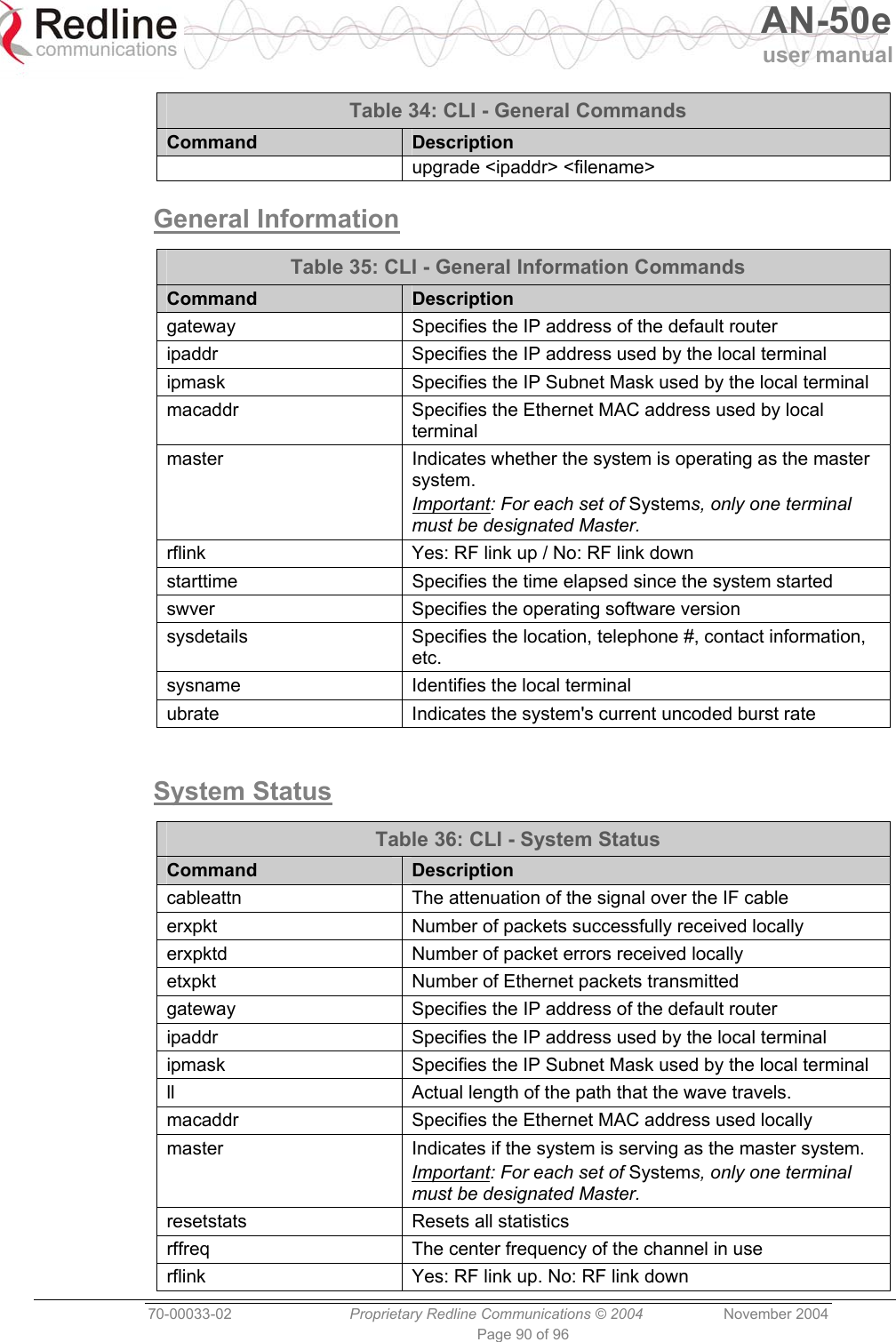
![AN-50e user manual 70-00033-02 Proprietary Redline Communications © 2004 November 2004 Page 89 of 96 General Commands Table 34: CLI - General Commands Command Description chgver Swaps the operating and secondary software versions get Get <parameter name> displays the value for a status parameter. For configuration parameters, use Set command. login Allows login under a different username and password logout Disconnects user from the terminal. passwd Change password for user. passwd <username> <newpassword> reboot Reboots the terminal. Reboot <time in seconds> resetstats Resets all statistics save config Permanently saves system configuration settings. This command is required to activate all Configuration settings set previously save snmp Permanently saves SNMP configuration settings. This command is required to activate all SNMP settings set previously. set Set one configuration parameter: <parameter name> [<value>] Without <value>, ‘set’ returns the actual value for configuration parameters. For status parameters, use the Get command. show config Returns a list of all System Configuration parameters. show log Returns a list of current system log entries. show snmp Returns a list of all SNMP communities and related parameters. show stats Returns a list of all System Status parameters. snmpaccess Modify access rights for a community (see snmpcomm) snmpaccess <community name> <access> snmpcomm To add a new SNMP community: snmpcomm add <community name> <access> <access> can be: r,w,t or any combination To delete an SNMP community snmpcomm del <community name> snmptrap To add a trap destination for an SNMP community: snmptrap add <community name> <IP destination> To delete a trap destination for an SNMP community: snmptrap del <community name> <IP destination> test config Allows testing of configuration settings for 5 minutes, after which the system reverts to the previously saved settings. To make settings permanent use 'save' command. upgrade Begin a software upload.](https://usermanual.wiki/Redline-Communications/AN5030EX.USERS-MANUAL-2/User-Guide-492957-Page-89.png)