Redline Communications AN80I BROADBAND WIRELESS SYSTEM User Manual 70 00072 01 01 DRAFT
Redline Communications Inc. BROADBAND WIRELESS SYSTEM 70 00072 01 01 DRAFT
UserManual.wiki
>
Redline Communications
>
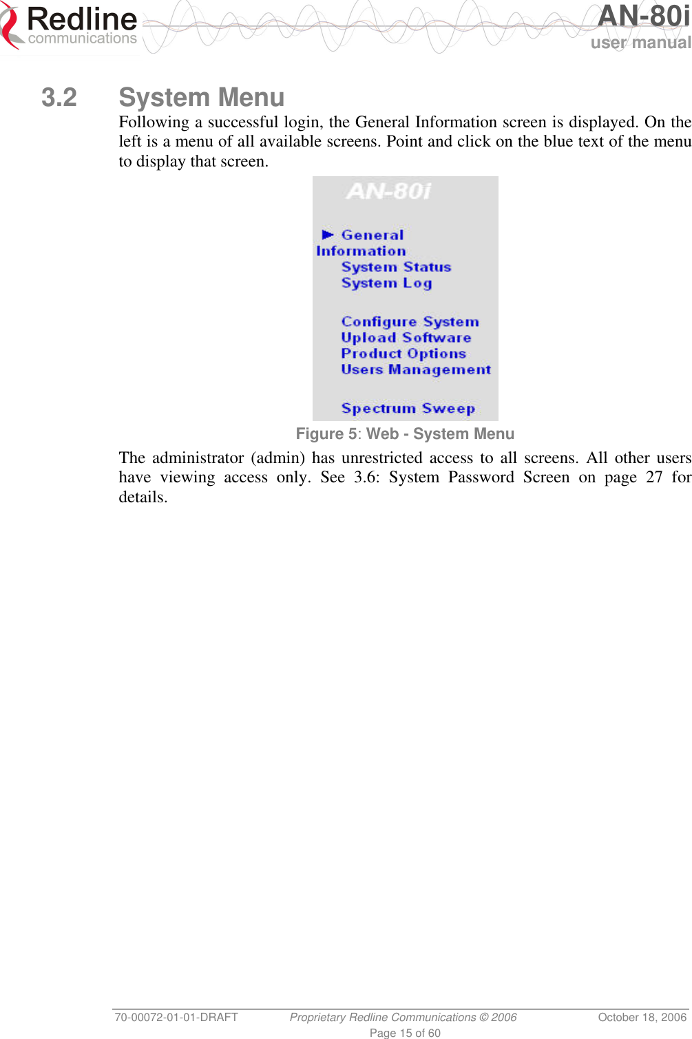
AN80I User Manual
>
USERS MANUAL
Contents
1.
USERS MANUAL
2.
USERS MANUAL 1
3.
USERS MANUAL 2
USERS MANUAL
Navigation menu
Upload a User Manual
Namespaces
Wiki Guide
HTML
PDF
Info
Views
User Manual
Discussion / Help
Navigation

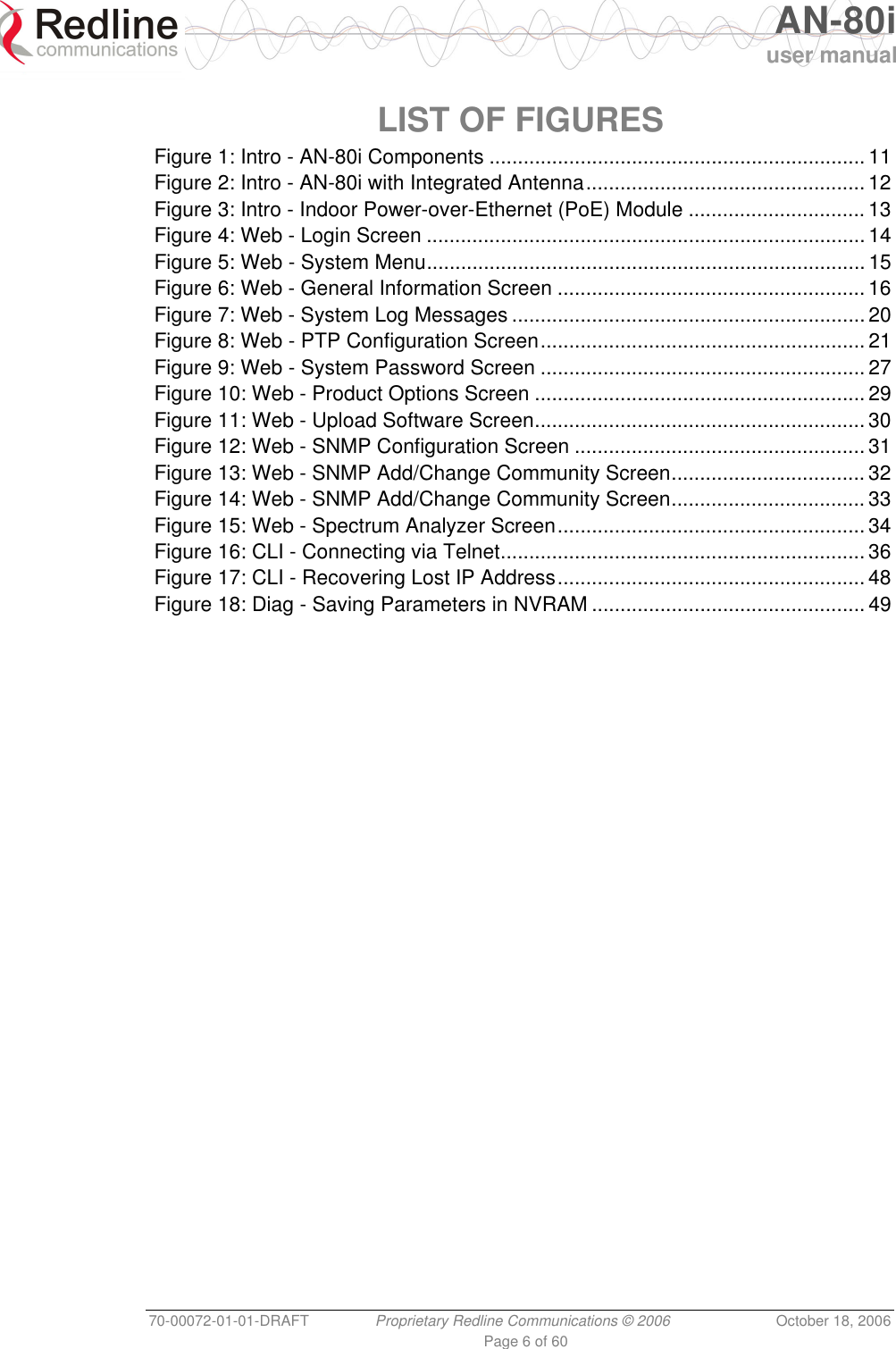

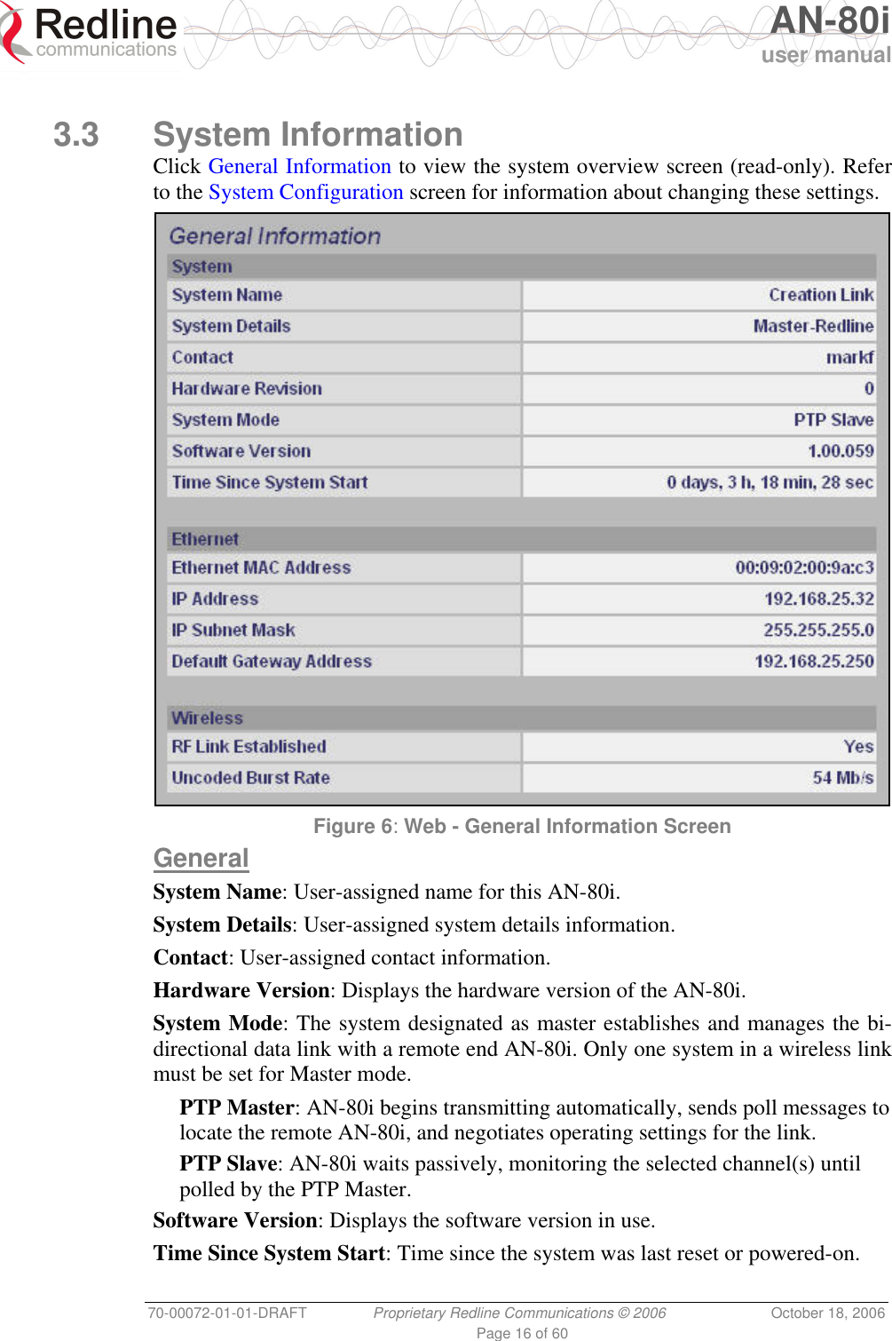
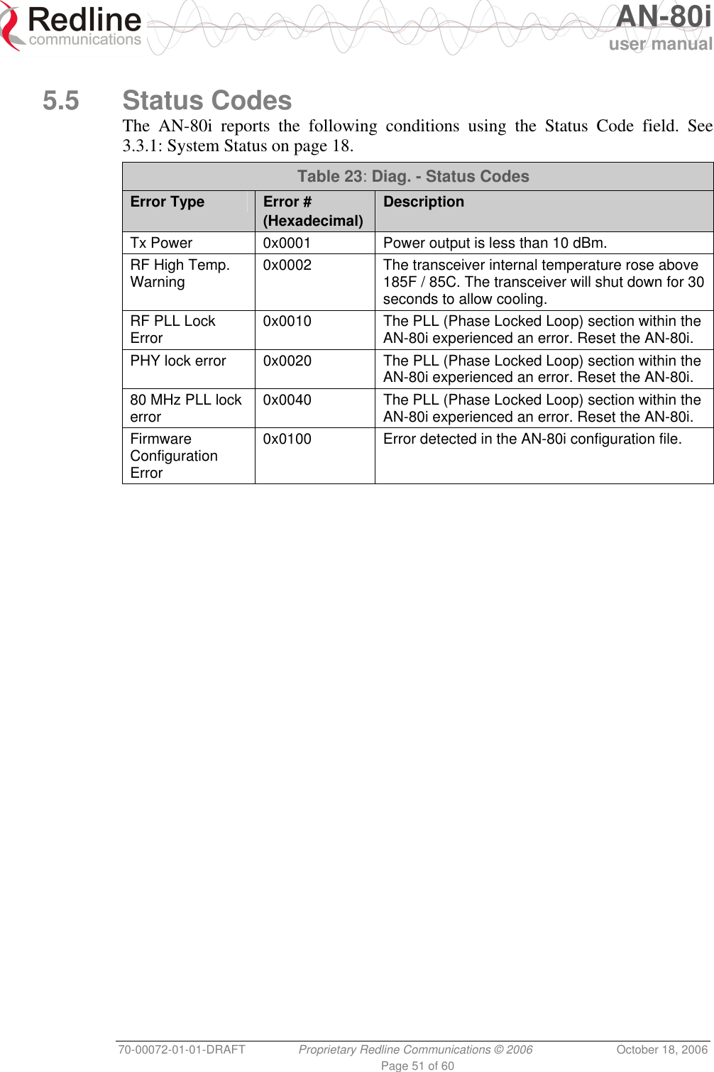
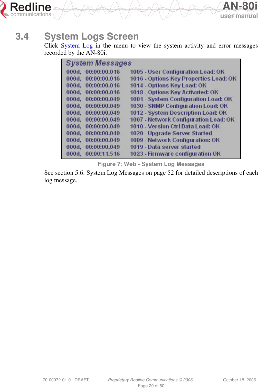
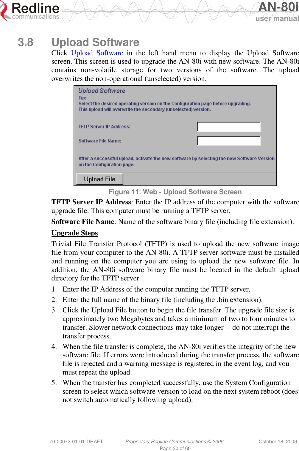
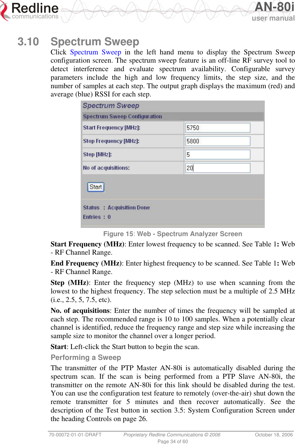
![AN-80i user manual 70-00072-01-01-DRAFT Proprietary Redline Communications © 2006 October 18, 2006 Page 19 of 60 RF Channel Frequency: User-assigned RF channel. Tx Power: The current transmit power level. If ATPC is enabled, this value may be different than the Tx Power setting in the System Configuration screen. Link Distance [Miles or Km]: Distance between wireless systems. This may be the calculated or user-assigned distance (System Configuration screen). RF Status [Error Code]: A status code indicating the condition of the system RF components. See 5.5: Status Codes on page 51. Ethernet MAC Address: System hardware address. This is also printed on a label affixed to the AN-80i. IP Address: User-assigned IP address of the AN-80i. IP Subnet Mask: User-assigned IP subnet mask. Default Gateway Address: User-assigned IP for the default router or gateway. Ethernet LAN Statistics Rx Packets: Total packets received on the Ethernet port. Rx Packets: Discarded: Total valid Ethernet frames received on the Ethernet port that are discarded due to lack of buffer space. Tx Packets: Number of packets transmitted on the Ethernet port (including Ethernet frames and error correction bytes). Wireless Statistics Received Signal Strength: Min: Minimum measured RSSI value. Received Signal Strength: Mean: Average measured RSSI value. Received Signal Strength: Max: Maximum measured RSSI value. SINADR: Average signal to interference, noise, and distortion ratio measured since the last screen refresh. The measurement includes the effects of AGC. Rx Packets: Total number of packets received over the wireless interface. Rx Packets: Retransmitted Number of packets received over the wireless interface that were retransmitted by the remote-end system (ARQ mechanism re-transmitting unacknowledged packets). Rx Packets - Discarded: Number of received packets discarded due to errors. Tx Packets: Number of packets transmitted over the wireless interface. Tx Packets - Retransmitted: Number of packets re-transmitted over the wireless interface (ARQ mechanism re-transmitting unacknowledged packets). Tx Packets: Discarded: Total number of packets transmitted over the wireless interface that were not acknowledged (discarded by remote-end due to errors). Controls Reset Statistics: Click this button to zero the counters for the wireless and Ethernet LAN Statistics displayed on this page.](https://usermanual.wiki/Redline-Communications/AN80I.USERS-MANUAL/User-Guide-721333-Page-19.png)
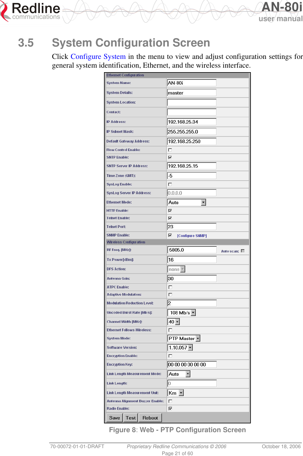
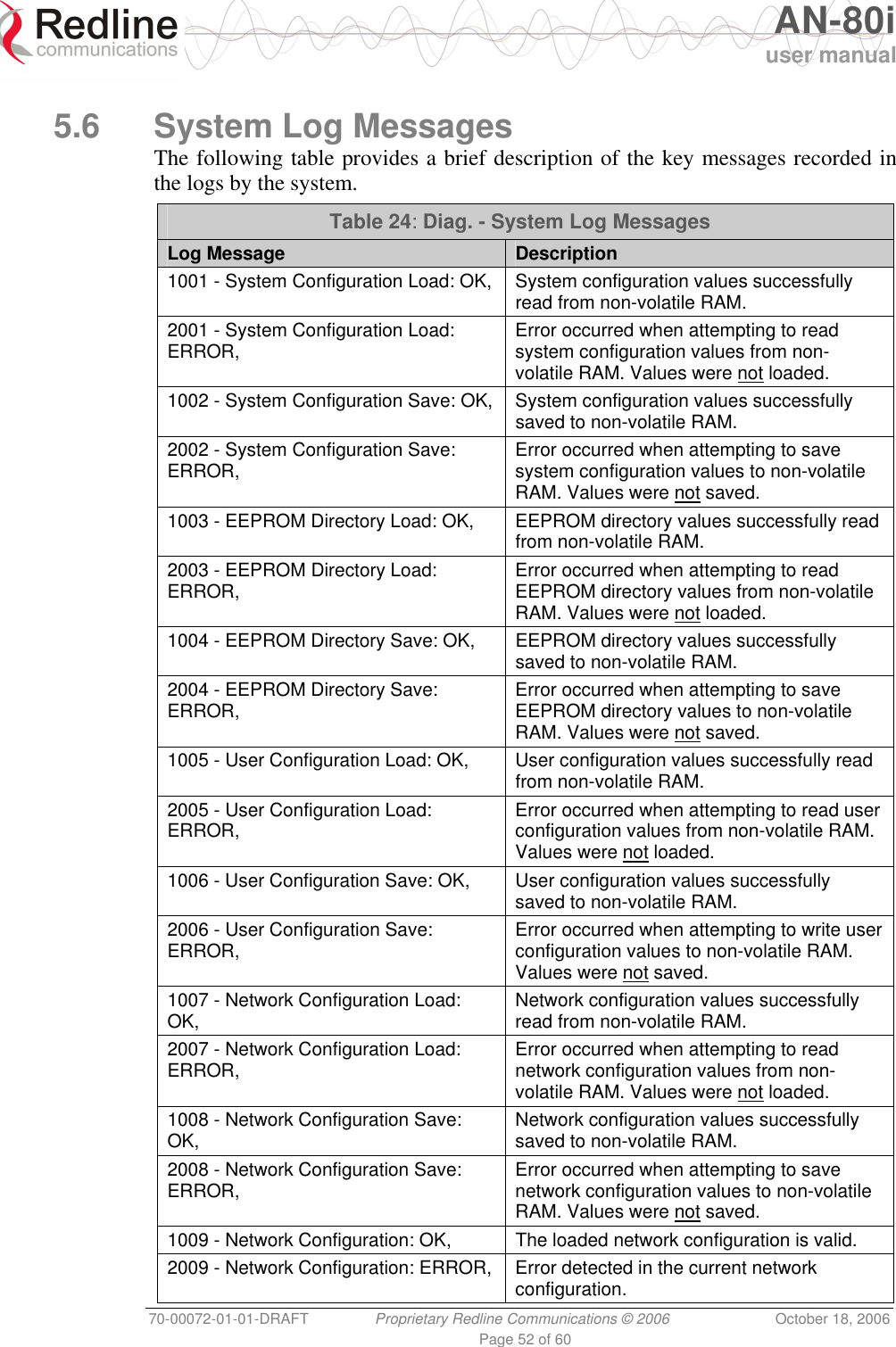
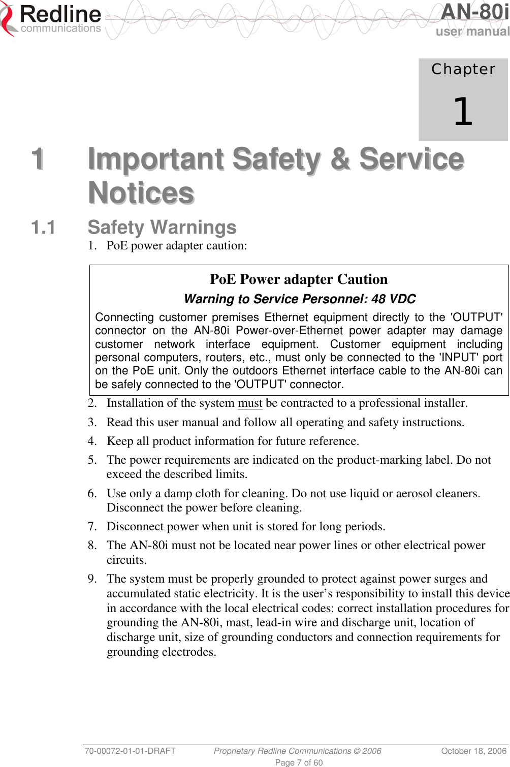
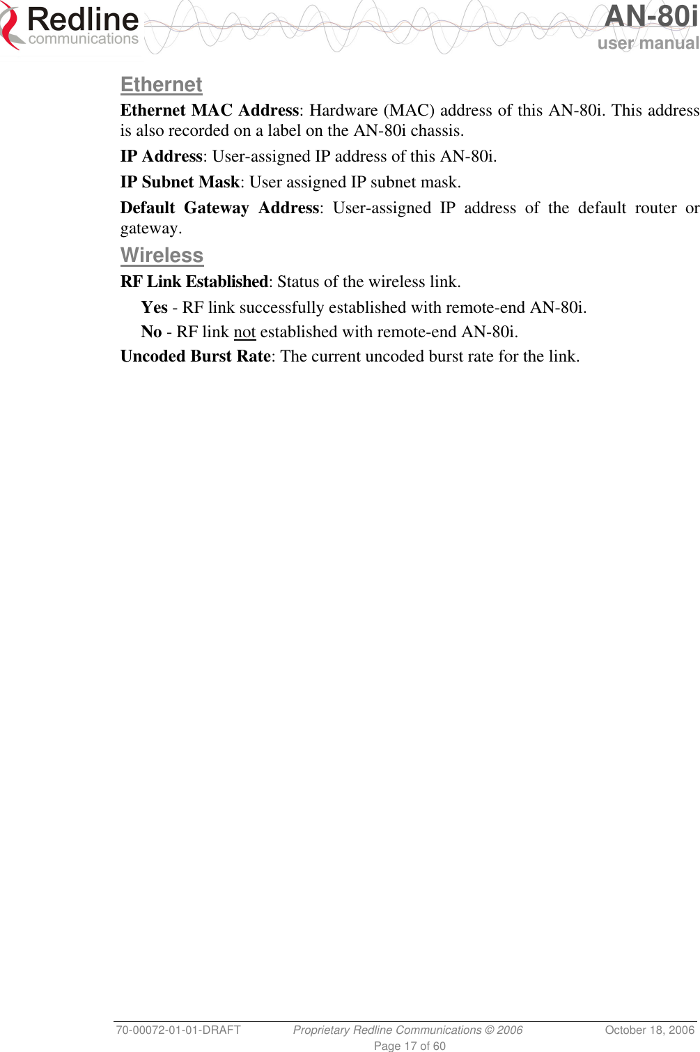
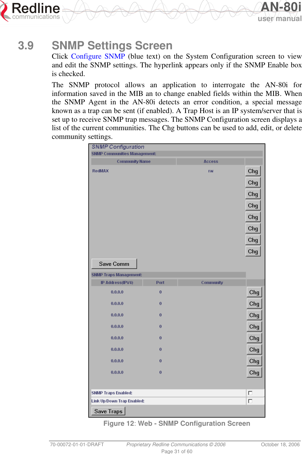
![AN-80i user manual 70-00072-01-01-DRAFT Proprietary Redline Communications © 2006 October 18, 2006 Page 23 of 60 HTTP Enable: Check this box to enable the HTTP (Web) interface. If the option is deselected, only CLI commands will be available. Telnet Enable: Check this box to enable a Telnet access (CLI) to the AN-80i. Refer to the CLI commands in section 4: CLI Interface on page 36. Telnet Port: Enter Telnet port address (default is 23). SNMP Enable: Check this box to enable the Simple Network Management Protocol (SNMP) agent. When this item is checked, clicking on the blue text [Configure SNMP] adjacent to the check box displays the SNMP Configuration screen. See section 3.9: SNMP Settings on page 31 for additional information on SNMP settings for the AN-80i. Wireless Configuration RF Freq. [MHz]: Enter the center frequency for the RF channel. The options key controls channel availability. The table below specifies the center frequencies of each available channel. Table 1: Web - RF Channel Range Channel Size Frequency Selection (2.5 MHz steps) 10 MHz 5730 - 5845 MHz 20 MHz 5735 - 5840 MHz 40 MHz 5745 - 5830 MHz To minimize interference, the channel frequencies for AN-80i links operating in close proximity should be separated by a minimum of the channel size in use (to avoid overlapping bands). Auto scan: Check this box to enable the AN-80i PTP Slave to automatically scan available channels and locate the current operating frequency of the AN-80i PTP Master. Tx Power [dBm]: Enter the transmit power level (dBm). This setting is for the transceiver output only. The actual EIRP depends on the gain of the connected antenna (see section 6.2: Antenna and Power Specifications on page 56). Important: In some regions, the maximum operational power per channel for a specific antenna is limited in accordance with regulations specifying the maximum allowable EIRP levels. Refer to the FCC and CE notices in this manual. See Table 2: Web - Max. Power (in dBm) and Modulation to determine the maximum transmit power level available at each modulation setting. When ATPC is enabled, the Tx power will be automatically adjusted to achieve optimum performance. Table 2: Web - Max. Power (in dBm) and Modulation Settings Modulation BPSK QPSK 16 QAM 64 QAM Code Rate 1/2 3/4 1/2 3/4 1/2 3/4 2/3 3/4 Max Tx Power 20 20 20 20 20 20 16 16](https://usermanual.wiki/Redline-Communications/AN80I.USERS-MANUAL/User-Guide-721333-Page-23.png)
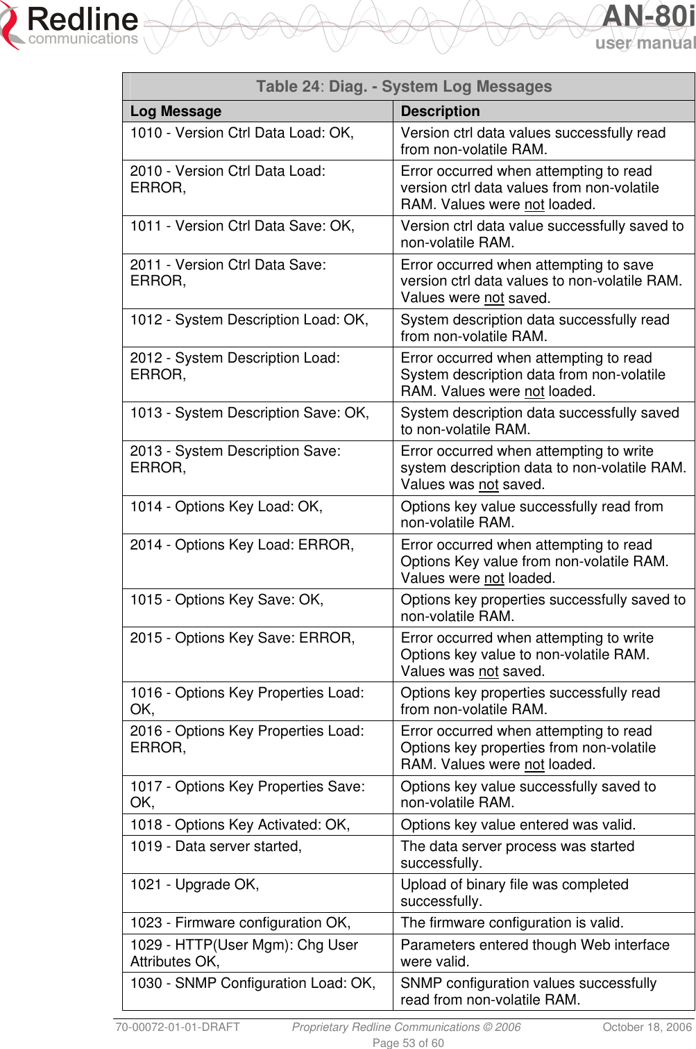
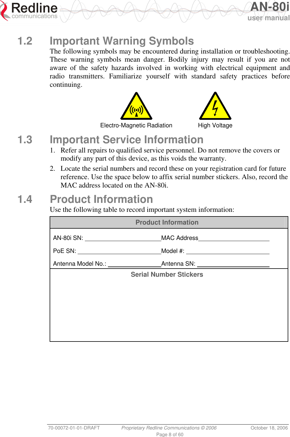
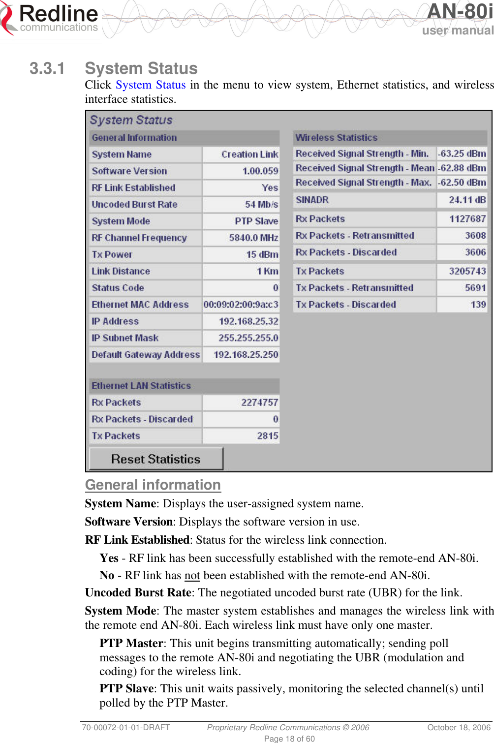
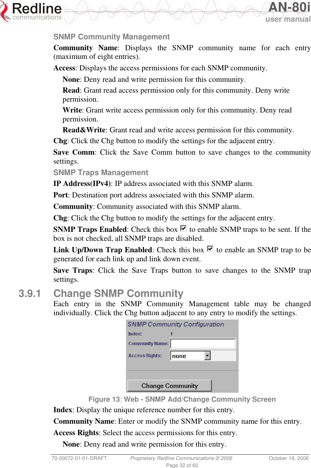
![AN-80i user manual 70-00072-01-01-DRAFT Proprietary Redline Communications © 2006 October 18, 2006 Page 25 of 60 Channel Width: Select the channel bandwidth. See Table 1: Web - RF Channel Range. Modulation Reduction Level: Enter the number of modulation/coding levels to step down during re-transmission of errored wireless packets. Each step down lowers the UBR. The level can be set from 0 to 7 (recommended value = 2). Uncoded Burst Rate [Mb/s]: Select the desired UBR for the link. If Adaptive Modulation is disabled, the AN-80i will transmit using only the specified settings. See Table 2: Web - Max. Power (in dBm) and Modulation. Ethernet Follows Wireless: Check this box to have the AN-80i disable and enable the Ethernet port function based on the status of the wireless interface. This feature allows switches and routers to trigger configuration changes based on changes to the AN-80i Ethernet port status. Disabled ( ): The AN-80i Ethernet port is always enabled. Enabled ( ): The Ethernet port status is controlled based on the status of the wireless interface. See the following table. Table 3: Web - Ethernet Status Indication Configuration Setting Wireless interface Status Ethernet Port Status Ethernet Follows Wireless Link Up Enabled Link Down Enabled Ethernet Follows Wireless Link Up Enabled Link Down Disabled Important: Enabling the Ethernet Follows Wireless setting affects all data and management traffic (HTTP, TELNET, and SNMP). While the wireless interface is down, it is not possible to establish communications with the AN-80i using the Ethernet port. If the wireless interface is down, the Ethernet Follows Wireless setting can only be set to 'off' by using the IP recovery procedure. See 5.2: Procedure to Reset AN-80i IP Address on page 48. System Mode: The PTP Master establishes and manages the bi-directional data link with a remote end AN-80i. Only one system in a wireless link must be set for PTP Master mode. PTP Master: This unit begins transmitting automatically; sends poll messages to the remote AN-80i, and negotiates the wireless link. PTP Slave: This unit waits passively, monitoring the selected channel(s) until polled by the PTP Master, and participates in negotiating the wireless link. Software Version: Select the version of system software to load when the AN-80i is rebooted. The system holds two independent software images. Encryption Enable: Check this box to enable encryption of data transmitted over the wireless interface. When encryption is enabled, no Ethernet packets can be transferred over-the-air unless encryption is enabled on the remote-end AN-80i, and the correct encryption key is entered on both AN-80i units.](https://usermanual.wiki/Redline-Communications/AN80I.USERS-MANUAL/User-Guide-721333-Page-25.png)
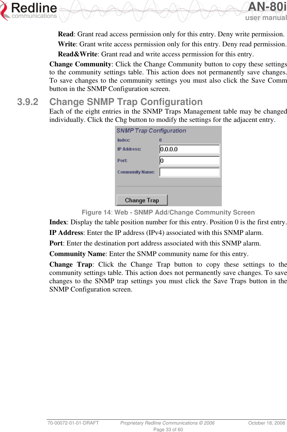
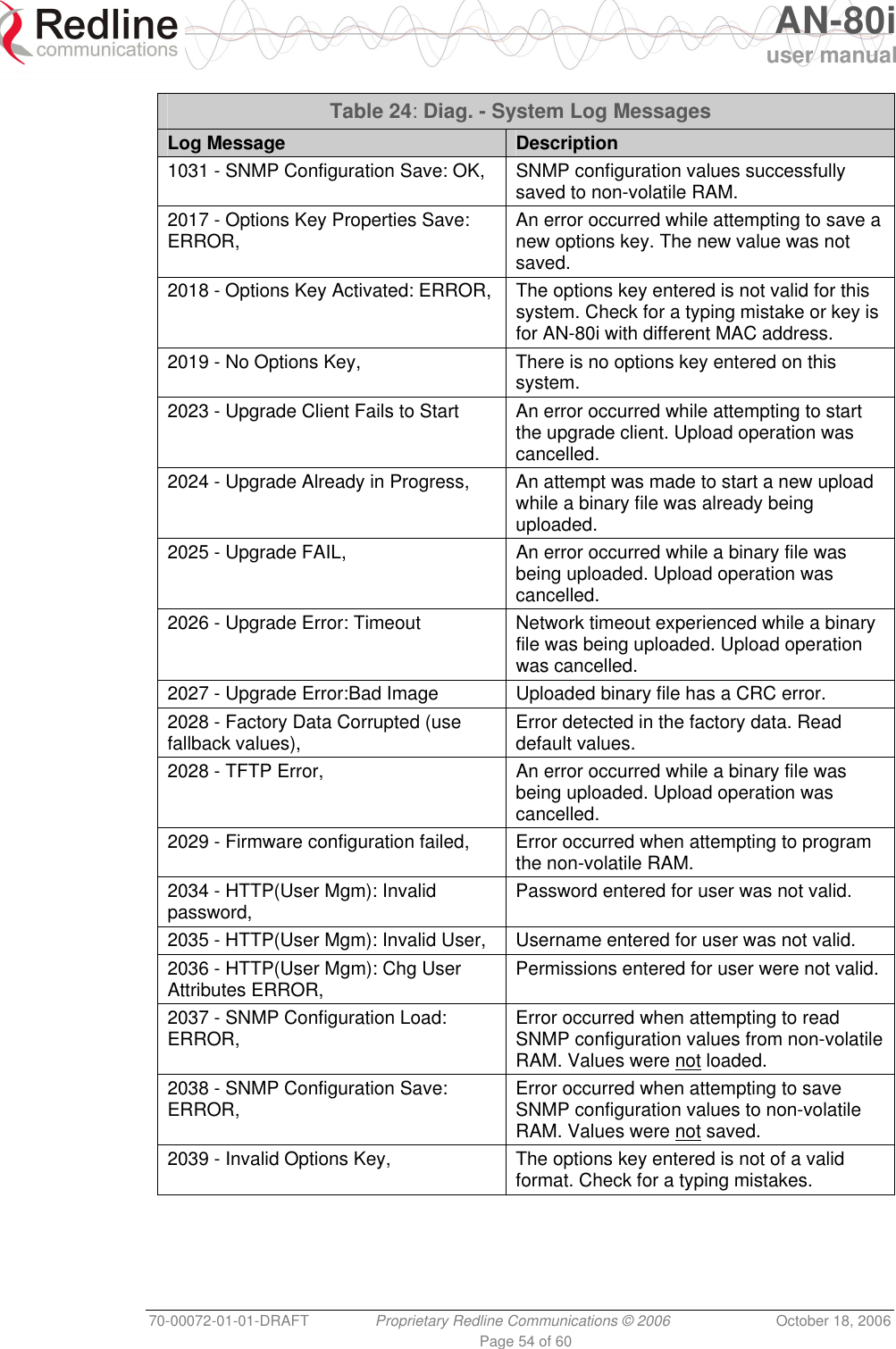
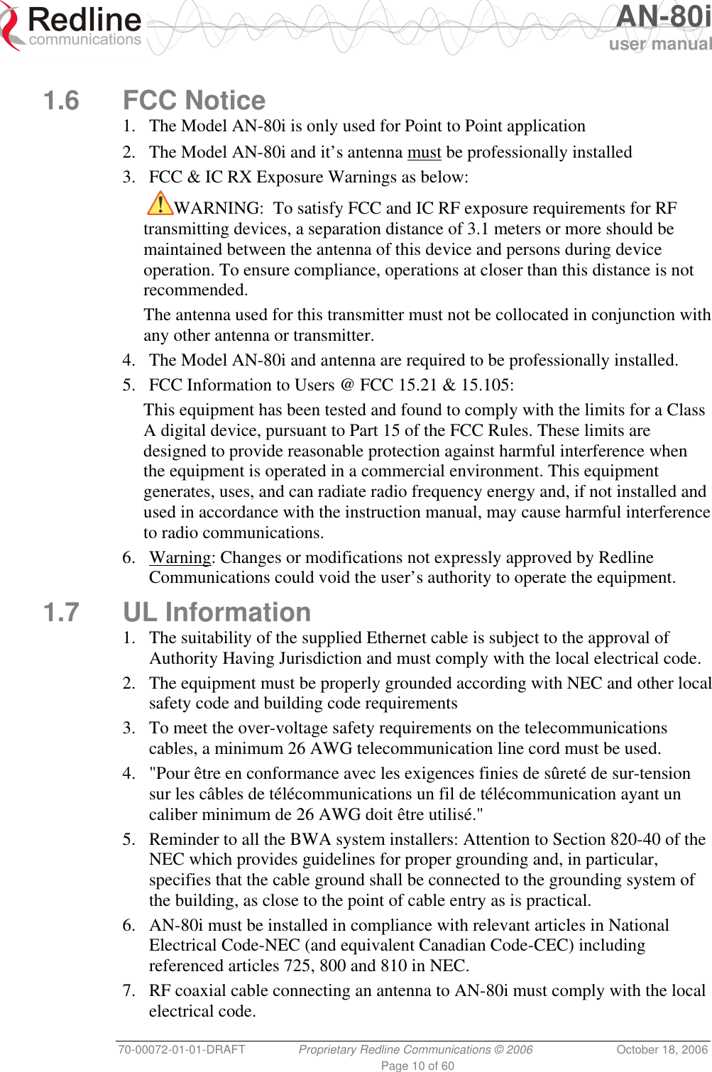
![AN-80i user manual 70-00072-01-01-DRAFT Proprietary Redline Communications © 2006 October 18, 2006 Page 36 of 60 Chapter 4 44 CCLLII IInntteerrffaaccee This section describes the procedures for configuring and operating the AN-80i using CLI over a Telnet connection. 4.1 Overview 4.1.1 Connecting via Telnet To connect to the AN-80i, open a Telnet session to the IP address of the AN-80i. On a Windows™ PC, open the Run command and type 'telnet' followed by the IP address of the AN-80i. When the command prompt screen appears, login to the AN-80i. The AN-80i may now be controlled using a set of CLI commands. Figure 16: CLI - Connecting via Telnet The system will logout users automatically if no commands are received (idle) for five minutes. To exit immediately from the CLI, type the following command: logout [ENTER]](https://usermanual.wiki/Redline-Communications/AN80I.USERS-MANUAL/User-Guide-721333-Page-36.png)
![AN-80i user manual 70-00072-01-01-DRAFT Proprietary Redline Communications © 2006 October 18, 2006 Page 38 of 60 4.2.1 Chgver Use the chgver command to change the software version to loaded when you reboot the AN-80i. Also see the Get command 'swver'. Table 9: CLI - chgver Command Parameter/Description chgver Enter this command to toggle between software versions. The setting will alternate between the two banks of memory (no parameters). chgver <Enter> 4.2.2 Get Use the get command to view system parameters. Use the following general format to view a parameter: get [field] <Enter> Table 10: CLI - get Command Parameter/Description get calcdst: Calculated link distance between units. erxpkt: Number of Ethernet packets received. erxpktd: Number of Ethernet packets received that were discarded. etxpkt: Number of Ethernet packets transmitted. mac: AN-80i MAC address. radiotype: Radio type. rffreq: Current RF frequency setting. rflink: Status of the RF link. rfstatus: Status RF transmitter. rssimax: Maximum RSSI. rssimean: Mean RSSI. rssimin: Minimum RSSI. sinadr: Ration of signal to interference + noise. swver: List the downloaded software versions. sysuptime: Display the time since the last reboot. txpower: Current Tx power setting. ubrate: Current UBR value. wrxpkt: Number of wireless packets received. wrxpktd: Number of wireless packets received that were discarded. wrxpktr: Number of wireless packets that were retransmitted. wtxpkt: Number of wireless packets transmitted. wtxpktd: Number of wireless packets transmitted that were discarded. wtxpktr: Number of wireless packets that were retransmitted. 4.2.3 Reboot Use the reboot command to remotely reset the AN-80i.](https://usermanual.wiki/Redline-Communications/AN80I.USERS-MANUAL/User-Guide-721333-Page-38.png)
![AN-80i user manual 70-00072-01-01-DRAFT Proprietary Redline Communications © 2006 October 18, 2006 Page 39 of 60 Table 11: CLI - reboot Command Parameter/Description reboot Reboot the AN-80i. There are no parameters associated with this command. reboot <Enter> 4.2.4 Reset Use the reset command to set all AN-80i statistics values to zero. Table 12: CLI - reset Command Parameter/Description reset stats: Reset the AN-80i statistics counters. reset stats <Enter> 4.2.5 Save Use the save command to copy edited parameter settings into non-volatile memory. See section 5.3: Testing and Saving System Parameters on page 49. save [option] <Enter> Table 13: CLI - save Command Parameter/Description save config: Save Ethernet, wireless, and user configuration settings. snmp: Save SNMP settings. defaultconfig: Overwrite current settings with the factory default Ethernet, wireless, and SNMP settings. 4.2.6 Set Use the set command to view and/or change a parameter. View a parameter: set [field] <Enter> Change a parameter: set [field] [value] <Enter> Table 14: CLI - set Command Parameter/Description set adaptmod: Enable or disable the adaptive modulation function. off - Disable on - Enable When enabled, the AN-80i will automatically change the modulation to the highest setting that can sustain a packet error rate lower than 1x10e-6. If the packet error rate exceeds 1x10e-6, the system automatically steps down modulation/code rate (i.e., from 16 QAM 3/4 to 16 QAM 1/2 ) to maintain the wireless link quality.](https://usermanual.wiki/Redline-Communications/AN80I.USERS-MANUAL/User-Guide-721333-Page-39.png)
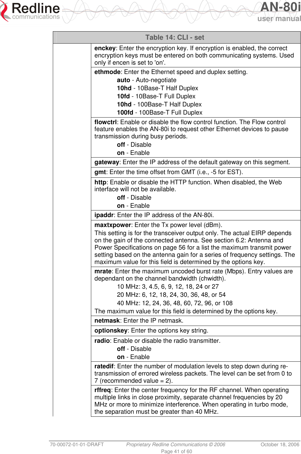
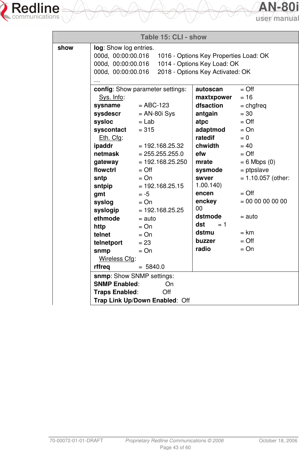
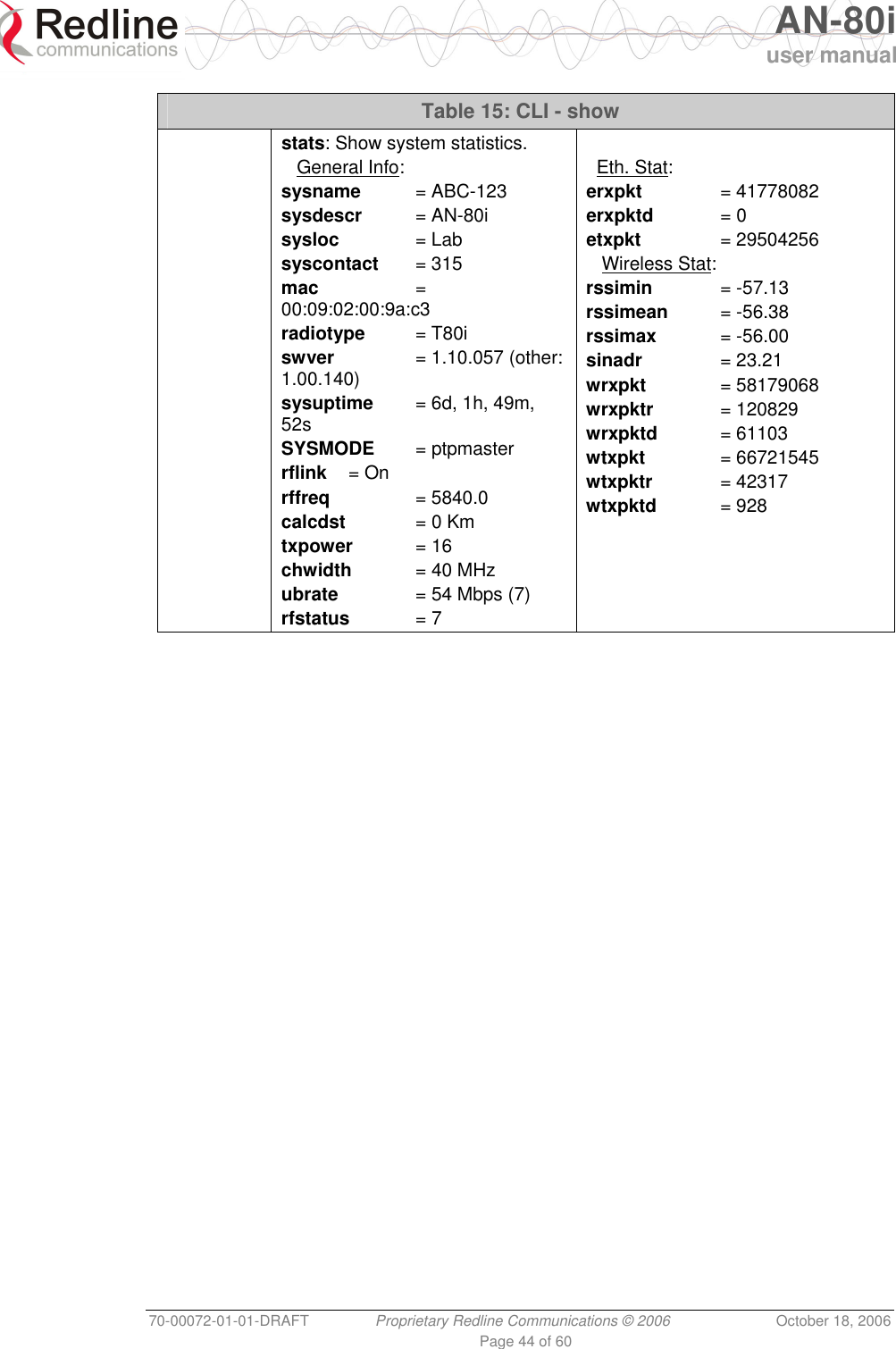
![AN-80i user manual 70-00072-01-01-DRAFT Proprietary Redline Communications © 2006 October 18, 2006 Page 42 of 60 Table 14: CLI - set snmp: SNMP enable setting. off - Disable the SNMP agent. on - Enable the SNMP agent. sntp: SNTP enable setting. off - Disable SNTP protocol support. on - Enable SNTP protocol support. sntpip: Enter the SNTP server IP address. Valid only if sntp is enabled. syscontact: Enter additional descriptive details about this AN-80i. The description can be any combination of up to 20 letters and numbers. sysdescr: Enter descriptive details about this AN-80i. The description can be any combination of up to 20 letters and numbers. sysloc: Enter descriptive details about the location of this AN-80i. The description can be any combination of up to 20 letters and numbers. syslog: Syslog enable setting. off - Disable syslog server protocol support. on - Enable syslog server protocol support. syslogip: Enter the syslog server IP address. Valid only if syslog is enabled. sysmode: The system designated as master establishes and manages the bi-directional data link with a remote end AN-80i. Only one system in a wireless link must be set for Master mode. ptpmaster - This unit begins transmitting automatically; sending poll messages to locate the remote AN-80i and then negotiates to establish the wireless link. ptpslave - This unit waits passively, monitoring the selected channel(s) until polled by the PTP Master, and then negotiates to establish the wireless link. sysname: Enter the name for this AN-80i. The name can be any combination of up to 20 letters and numbers. telnet: Enable or disable the Telnet port. If the Telnet port is disabled, it will not be possible to use the CLI interface. off - Disable on - Enable Changes to this field are effective only following reboot. telnetport: Enter Telnet port address (default is 23). 4.2.7 Show Use the show command to display system statistics. show <Enter> Change to 'show' mode. show [field] <Enter> Display values for the selected parameter. Table 15: CLI - show Command Description](https://usermanual.wiki/Redline-Communications/AN80I.USERS-MANUAL/User-Guide-721333-Page-42.png)
![AN-80i user manual 70-00072-01-01-DRAFT Proprietary Redline Communications © 2006 October 18, 2006 Page 45 of 60 4.2.8 Snmpcommunity Use the snmpcommunity command to configure SNMP community permissions. Table 16: CLI - snmpcommunity Command Description snmpcommunity add: add a new snmp community to the snmp community table. The index value is assigned automatically. Up to eight community entries can be entered in the table. snmpcommunity add <name> <string> <Enter> snmpcommunity add <rights> 0 | r | w | rw <Enter> Where. 0 (zero):Deny read and write permission. r: Grant read access permission only. Deny write permission. w: Grant write access permission only. Deny read permission. rw: Grant read and write access permission for this community. default: Set all snmp parameters to factory default settings. snmpcommunity default <idx> <Enter> del: Delete the specified community entry. snmpcommunity del <idx> <Enter> print: List all SNMP communities and associated permissions. snmpcommunity print <Enter> 4.2.9 Snmptrap Use the snmptrap command to configure the SNMP trap message reporting. Table 17: CLI - snmptrap Command Description snmptrap add: add a new snmp trap to the snmp trap table. The index value is assigned automatically. Up to eight settings can be entered. snmptrap add <ipaddr> <port> <community> <Enter> change: Modify the specified snmp setting. snmptrap change <idx> [-p <port>] [-i <ip_add>] [-c <community] <Ent> del: Delete the specified snmp setting. snmptrap del <idx> <Enter> print: List all SNMP trap settings. snmptrap print <Enter> 4.2.10 Test Use the test command to load the current edited (but not permanently saved) configuration settings. Table 18: CLI - test Command Parameter/Description test config - AN-80i configuration settings test config <Enter>](https://usermanual.wiki/Redline-Communications/AN80I.USERS-MANUAL/User-Guide-721333-Page-45.png)
![AN-80i user manual 70-00072-01-01-DRAFT Proprietary Redline Communications © 2006 October 18, 2006 Page 46 of 60 The system will operate using these setting for five minutes. During this five minute period, you may enter 'save' at any time to permanently save the running configuration. If you do not 'save' the configuration within five minutes, the AN-80i reboots -- discarding the unsaved settings and loading the last saved configuration. 4.2.11 Upgrade Use the upgrade command to upload a new software binary file to the AN-80i. Table 19: CLI - upgrade Command Description upgrade ipaddr: Enter the IP address of the FTP server. filename: Enter the name of the binary file to be uploaded to the AN-80i. upgrade <ipaddr> <filename> <Enter> You must specify the TFTP server address and the full name of the binary file (including .bin extension). The AN-80i software binary file must be located in the default directory of the TFTP server. 4.2.12 User Use the user command to manage user accounts, passwords, and user groups. When in user mode, only the <chgpasswd> field is available, since the user can change only his own password. The other commands are available only for members of the administrator group. Table 20: CLI - user Command Description user add: Administrators can use this command to add new user accounts. This option is available only for administrators. user add <username> <usertype> <Enter> chgpasswd: For the user accounts, the chgpasswd command must be executed without the <username> parameter -- user's can change only their own password. user chgpasswd [<username>] <Enter> Adminitrators can change their own password, or specify a <username> to change the password of the specified user account. user chgpasswd [<username>] <Enter> del: Administrators can use this command to delete user accounts. This option is available only for administrators. user del <username> <Enter> print: Administrators can use this command to display a list of user accounts. This option is available only for administrators. user print <Enter>](https://usermanual.wiki/Redline-Communications/AN80I.USERS-MANUAL/User-Guide-721333-Page-46.png)