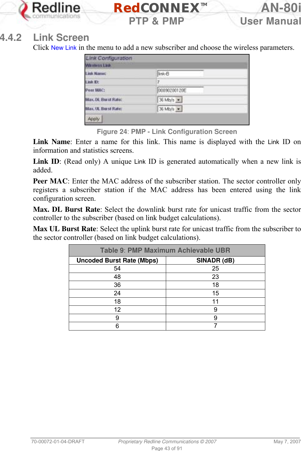
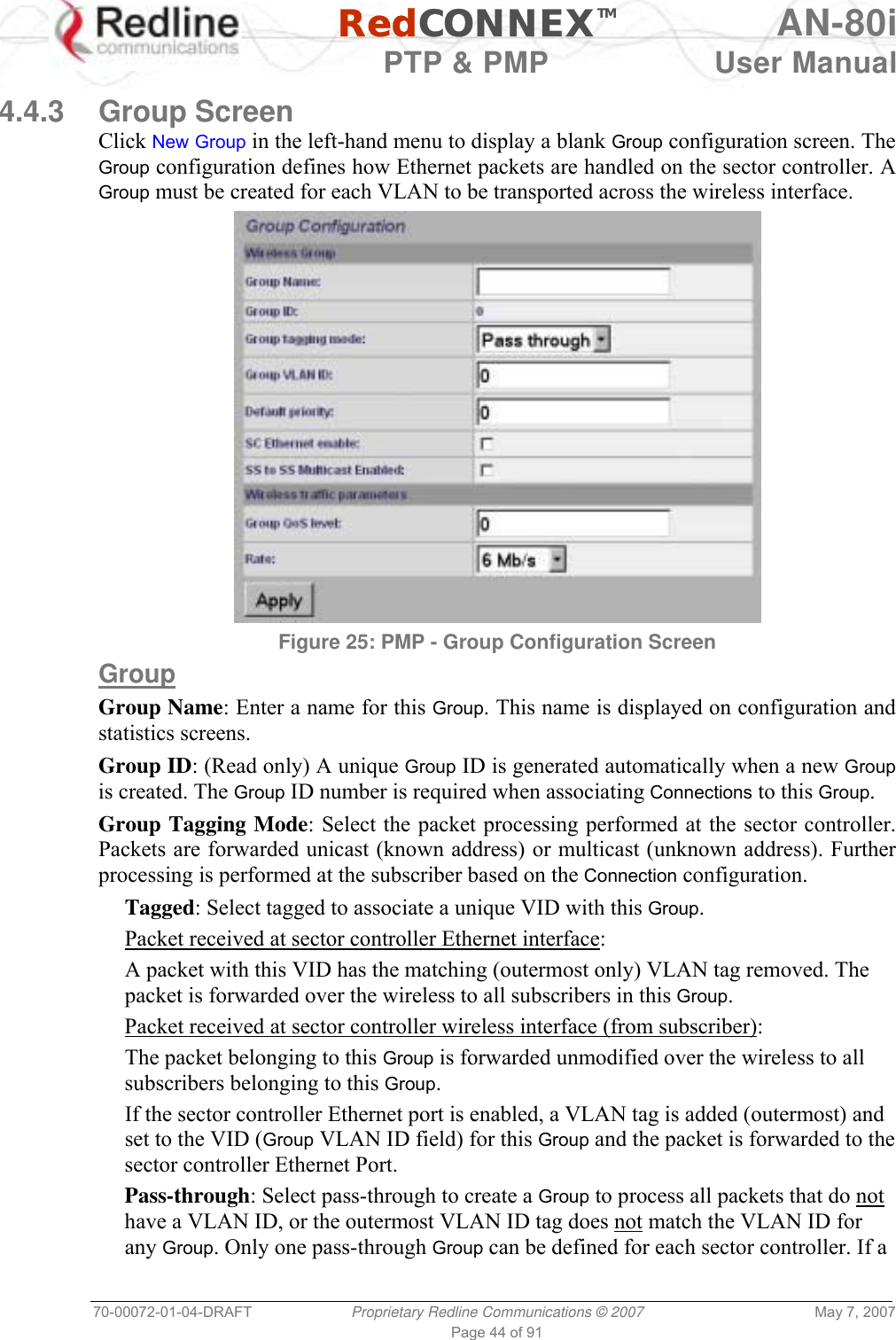
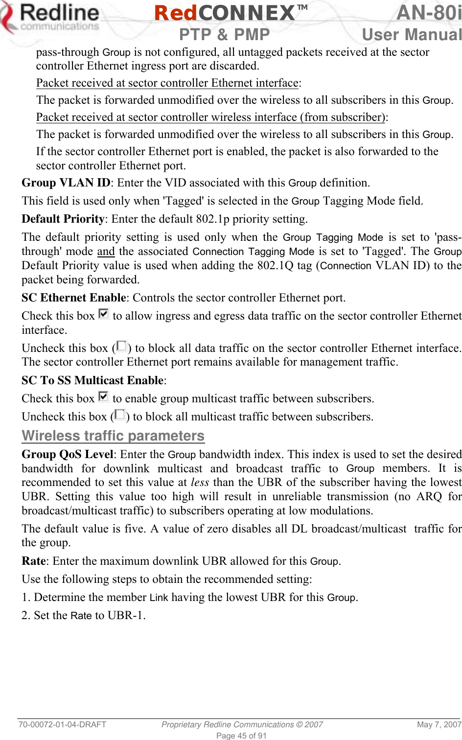
Redline Communications AN80I BROADBAND WIRELESS SYSTEM User Manual 70 00072 01 04 DRAFT
Redline Communications Inc. BROADBAND WIRELESS SYSTEM 70 00072 01 04 DRAFT
UserManual.wiki
>
Redline Communications
>
AN80I User Manual
>
USERS MANUAL 2
Contents
1.
USERS MANUAL
2.
USERS MANUAL 1
3.
USERS MANUAL 2
USERS MANUAL 2
Navigation menu
Upload a User Manual
Namespaces
Wiki Guide
HTML
PDF
Info
Views
User Manual
Discussion / Help
Navigation
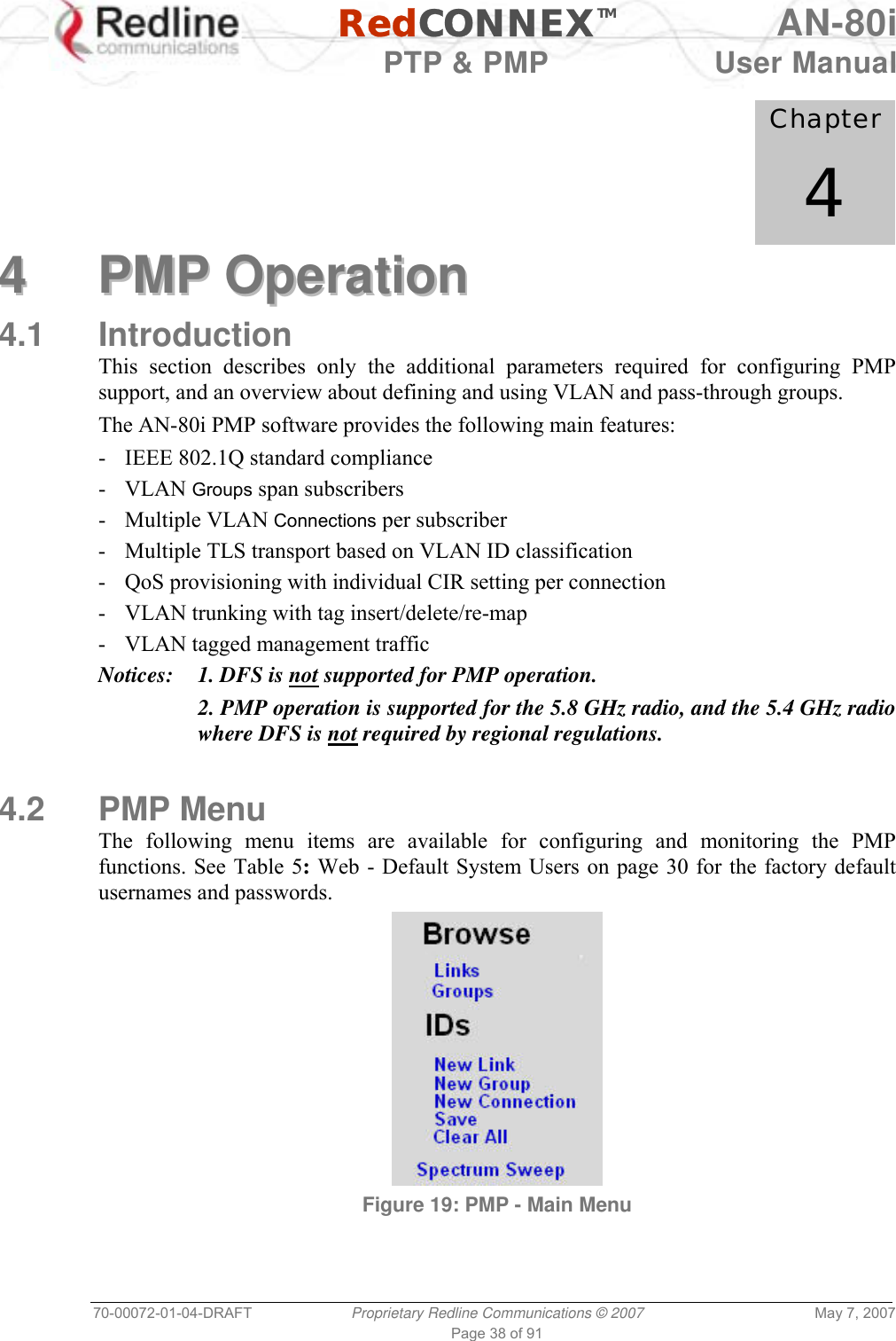
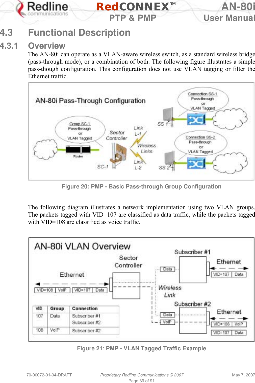
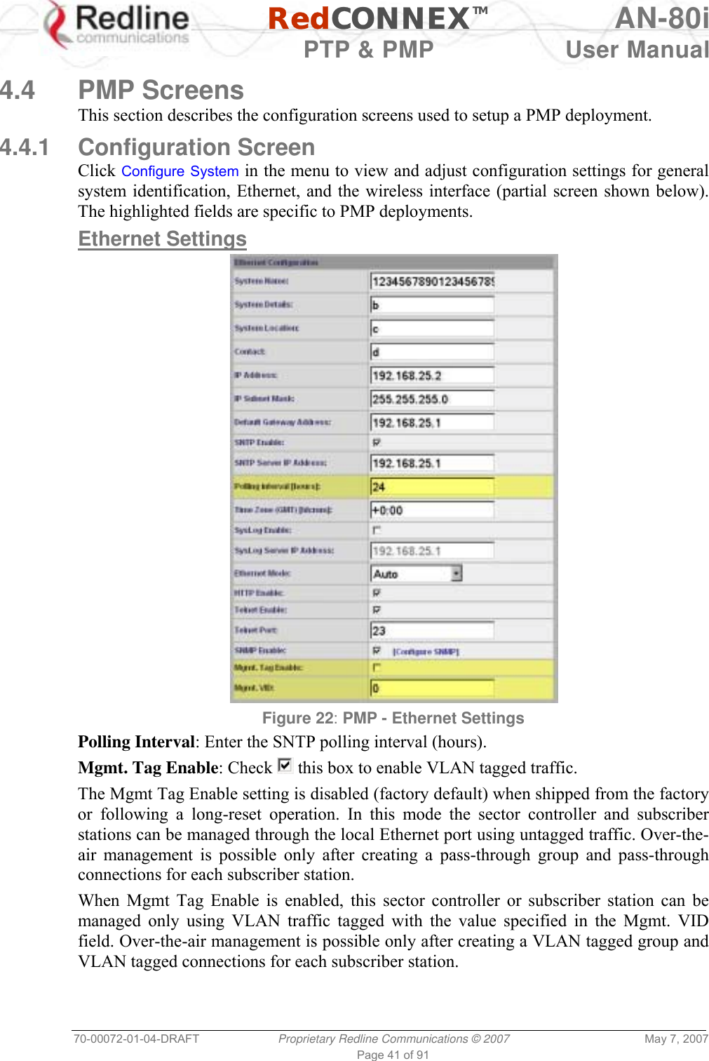
![RedCONNEXTM AN-80i PTP & PMP User Manual 70-00072-01-04-DRAFT Proprietary Redline Communications © 2007 May 7, 2007 Page 40 of 91 4.3.2 Minimum Setup Requirements A minimum set of parameters must be configured to enable data and management traffic on any PMP deployment: 1. Create one or more Links to identify each subscriber in the sector, and set the wireless link operating characteristics, including the maximum uplink and downlink modulation. 2. Create one or more Groups (VLAN or pass-through) and set the operating characteristics of this group. 3. Create one or more Connections (to Groups) for each subscriber, to assign membership to at least one Group. The following table provides a summary of the configuration shown in the pass-through configuration diagram above. The actual Group ID and Link ID values are not available until these items have been created during configuration of the system. This configuration passes all data traffic as a standard PMP configuration. Table 7: PMP - Basic Pass-Through Group Settings Group Configuration (Sector Controller) Connection Configuration (Subscriber) Group Name Port Tagging Group VID Connection Name Port Tagging Link ID Group ID ConnectionVID SC-1 Pass Through NA SS-1 Pass Through [L-1] [SC-1] NA SS-2 Pass Through [L-2] [SC-1] NA Notes: 1. The Group ID, Conn ID, and Link ID values are assigned automatically and must be read from the screen after items are created. 2. The QoS settings must be determined using the PMP Configuration Tool. 4.3.3 Packet Classification The AN-80i PMP deployment can be configured for use with VLAN tagged traffic, untagged traffic, or a combination these two types. Ingress packets received on the Ethernet port are classified into tagged or pass-through groups according to the criteria in the following table. The Group settings apply to packets processed at the sector controller, while Connection settings apply to packets processed at the subscriber. Table 8: PMP - Packet Classification Type Description Tagged Traffic Packet has a VLAN tag and there is a Group/Connection configured for this VID. Sector Controller: Packets are forwarded over the wireless link to all subscribers with Connections to this VLAN Group. Subscribers: Packets are forwarded to the sector controller. The sector controller forwards the packets to the local Ethernet port and subscribers with Connections to this VLAN Group. Pass-Through Traffic The packet does not have a VLAN tag, or no Group/Connection exists for this VID. If a pass-through Group has not been defined, unclassified packets are discarded. If a pass-through Group has been defined, classified packets are forwarded based on the rules for tagged traffic. The packet VLAN information is not modified.](https://usermanual.wiki/Redline-Communications/AN80I.USERS-MANUAL-2/User-Guide-790831-Page-3.png)
![RedCONNEXTM AN-80i PTP & PMP User Manual 70-00072-01-04-DRAFT Proprietary Redline Communications © 2007 May 7, 2007 Page 42 of 91 It is recommended to create and test a VLAN group for tagged management traffic before activating the Mgmt Tag Enable function. Set the associated QoS and priority values to ensure management traffic has adequate priority and bandwidth during system operation. Mgmt. VID: Enter the VLAN ID. When Mgmt. Tag Enable is selected, the system recognizes only management commands with this VLAN ID. Important: The VLAN network support should be verified before enabling this feature to ensure the AN-80i system will be reachable using the VLAN tagged traffic. Wireless Settings The highlighted wireless settings are specific to PMP deployments. Figure 23: PMP - Wireless Settings System Mode: The system designated as sector controller establishes and manages the bi-directional data link with a remote end AN-80i. Only one system in a wireless link must be set for Sector Controller mode. PTP Sector Controller: AN-80i begins transmitting automatically, sends poll messages to locate remote AN-80i subscribers, and negotiates operating settings for the link. PTP Subscriber: AN-80i waits passively, monitoring the selected channel(s) until polled by the PTP Sector Controller. Registration Period: The polling period for detecting new subscribers. Period is based on the number of wireless frames transmitted. Permitted values are 1 to 400. The recommended default registration period is 4. Max. Distance [km]: Enter the distance to the subscriber located farthest away from the sector controller (outer boundary of sector). This parameter is used to optimize communications with the subscribers.](https://usermanual.wiki/Redline-Communications/AN80I.USERS-MANUAL-2/User-Guide-790831-Page-5.png)
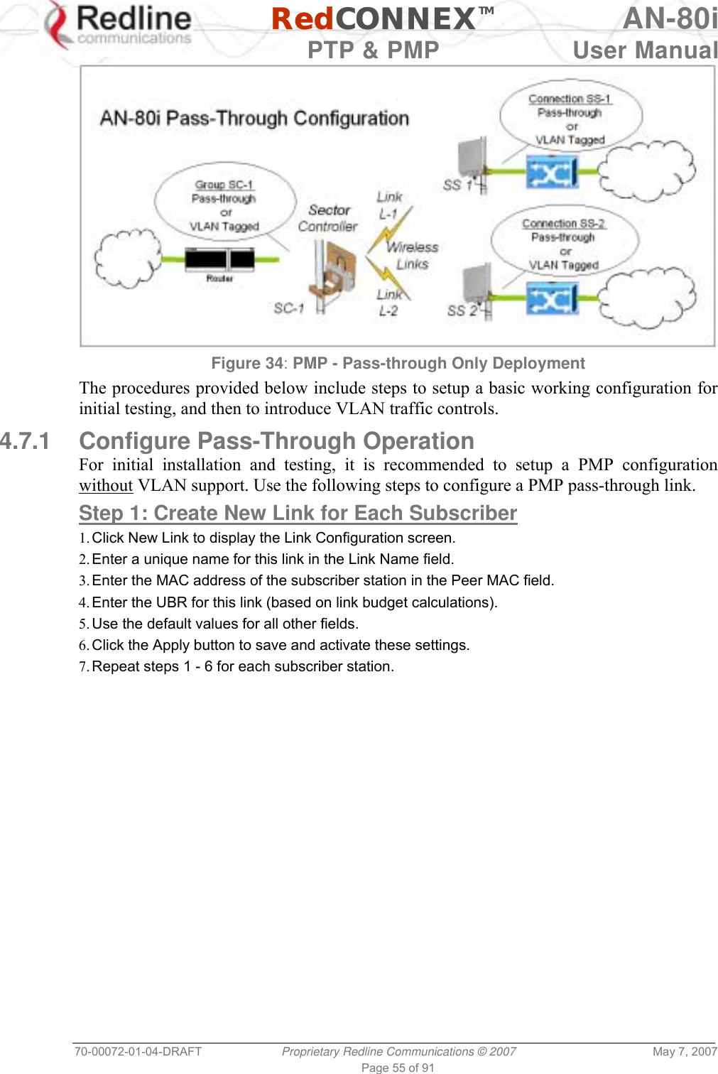
![RedCONNEXTM AN-80i PTP & PMP User Manual 70-00072-01-04-DRAFT Proprietary Redline Communications © 2007 May 7, 2007 Page 56 of 91 Step 2: Create Single Pass-through Group 1. Click New Group to display the Group Configuration screen. 2. Enter a unique name for this group in the Group Name field. 3. Set the Group Tagging Mode to Pass-through. 4. Check the SC Ethernet Enable box . 5. Set the Group QoS value for sending multicasts (i.e., 5). A value of zero (0) disables all traffic. 6. Use the default values for all other fields. 7. Click the Apply button to save and activate these settings. Step 3: Create Connections 1. Click New Connection to display the Connection Configuration screen. 2. Enter a unique name for this connection in the Connection Name field. 3. Set the Connection Tagging Mode to Pass-through. 4. Enter the Link ID of a subscriber station in the Link ID field. 5. Enter the Group ID in the Group ID field. 6. Set the DL QoS Level and UL QoS Levels. Default values are MAX Burst Rate Value - 1. A value of zero (0) disables all traffic. 7. Click the Apply button to save and activate these connection settings. 8. Repeat steps 1 - 7 to add a connection for each subscriber station. Step 4: Save Configuration Click Save in the left-hand menu to permanently save all settings. The system will pass all tagged and untagged data and management traffic. The following table provides sample settings for a pass-though group at the sector controller and connections to two subscriber stations. Table 10: PMP - Basic Pass-Through Group Configuration Settings Group Configuration (SC) Connection Configuration (SS) Group Name Group Tagging Mode Group VLAN ID Connection Name Connection Tagging Mode Link ID Group ID Connection VLAN ID SC-1 Pass Through NA SS-1 Pass Through [L-1]* [SC-1]* NA SS-2 Pass Through [L-2]* [SC-1]* NA *The group ID and link ID are numbers generated automatically by the AN-80i.](https://usermanual.wiki/Redline-Communications/AN80I.USERS-MANUAL-2/User-Guide-790831-Page-19.png)
![RedCONNEXTM AN-80i PTP & PMP User Manual 70-00072-01-04-DRAFT Proprietary Redline Communications © 2007 May 7, 2007 Page 59 of 91 Table 12: CLI - Root Mode Commands PTP PMP Command Description √ √ ? Use the '?' character to display help for any command or mode. Example: From the root directory, enter the following command to list all parameters that can be changed using the 'set' command: set ? √ √ CTRL-Z Return to root mode. Cancel command entry (alternative to backspace delete). √ √ exit Return to parent node / mode. all (exit all) Return to root mode. √ √ logout Terminate this telnet session. May be entered from any mode. 5.2 Connecting with Telnet To connect to the AN-80i, open a Telnet session to the IP address of the AN-80i. On a Windows™ PC, open the Run command and type 'telnet' followed by the IP address of the AN-80i. When the command prompt screen appears, login to the AN-80i. The AN-80i may now be controlled using a set of CLI commands. Figure 35: CLI - Connecting via Telnet The system will logout users automatically if no commands are received (idle) for five minutes. To exit immediately from the CLI, type the following command: logout [ENTER]](https://usermanual.wiki/Redline-Communications/AN80I.USERS-MANUAL-2/User-Guide-790831-Page-22.png)
![RedCONNEXTM AN-80i PTP & PMP User Manual 70-00072-01-04-DRAFT Proprietary Redline Communications © 2007 May 7, 2007 Page 60 of 91 5.3 CLI Command Set 5.3.1 Chgver Use the chgver command to change the software version to loaded when you reboot the AN-80i. Also see the Get command 'swver'. Table 13: CLI - chgver PTP PMP Parameter/Description √ √ Enter this command to toggle between software versions. The setting will alternate between the two banks of memory (no parameters). chgver <Enter> 5.3.2 Clear Use the clear command to delete all IDs from an ID table. Table 14: CLI - clear PTP PMP Parameter/Description √ clear idtable - Clear all the IDs 5.3.3 Del Use the del command to delete a specific ID. Table 15: CLI - del PTP PMP Parameter/Description √ del <id> - [id number] 5.3.4 Enable Use the enable command to re-enable a specific ID (that was disabled). Table 16: CLI - enable PTP PMP Parameter/Description √ enable <id> - [id number]](https://usermanual.wiki/Redline-Communications/AN80I.USERS-MANUAL-2/User-Guide-790831-Page-23.png)
![RedCONNEXTM AN-80i PTP & PMP User Manual 70-00072-01-04-DRAFT Proprietary Redline Communications © 2007 May 7, 2007 Page 61 of 91 5.3.5 Get Use the get command to view system parameters. Use the following general format to view a parameter: get [field] <Enter> Table 17: CLI - get PTP PMP Parameter/Description √ calcdst: Calculated link distance between units. √ √ erxpkt: Number of Ethernet packets received. √ √ erxpktd: Number of Ethernet packets received that were discarded. √ √ etxpkt: Number of Ethernet packets transmitted. √ √ mac: AN-80i MAC address. √ √ radiotype: Radio type. √ √ rffreq: Current RF frequency setting. √ rflink: Status of the RF link. √ √ rfstatus: Status RF transmitter. √ rssimax: Maximum RSSI. √ rssimean: Mean RSSI. √ rssimin: Minimum RSSI. √ sinadr: Ration of signal to interference + noise. √ √ swver: List the downloaded software versions. √ √ sysuptime: Display the time since the last reboot. √ √ txpower: Current Tx power setting. √ ubrate: Current UBR value. √ wrxpkt: Number of wireless packets received. √ wrxpktd: Number of wireless packets received that were discarded. √ wrxpktr: Number of wireless packets that were retransmitted. √ wtxpkt: Number of wireless packets transmitted. √ wtxpktd: Number of wireless packets transmitted that were discarded. √ wtxpktr: Number of wireless packets that were retransmitted. √ activeids: Number of active IDs. √ activelinks: Number of the active links. √ boardtype: Board type. √ dldpkt: Downlink discarded packets counter. √ dlrpkt: Downlink Rx packets counter. √ dltpkt: downlink Tx packets counter. √ idenable: ID status. √ lactive: Link active status. √ ldlblk: Downlink total blocks counter.](https://usermanual.wiki/Redline-Communications/AN80I.USERS-MANUAL-2/User-Guide-790831-Page-24.png)
![RedCONNEXTM AN-80i PTP & PMP User Manual 70-00072-01-04-DRAFT Proprietary Redline Communications © 2007 May 7, 2007 Page 63 of 91 5.3.7 New Use the new command to create a new link, group, or connector ID. Table 19: CLI - new PTP PMP Parameter/Description √ new <id_type> - [link | group | conn] <id> - <id number> 5.3.8 Reset Use the reset command to set all AN-80i statistics values to zero. Table 20: CLI - reset PTP PMP Parameter/Description √ √ stats: Reset the AN-80i statistics counters. reset stats <Enter> 5.3.9 Save Use the save command to copy edited parameter settings into non-volatile memory. save [option] <Enter> Table 21: CLI - save PTP PMP Parameter/Description √ √ config: Save Ethernet, wireless, and user configuration settings. snmp: Save SNMP settings. defaultconfig: Overwrite current settings with the factory default Ethernet, wireless, and SNMP settings. 5.3.10 Script Use the script command to save a file containing a string of CLI commands that can be used to restore the current (active) configuration of the AN-80i. Table 22: CLI - script PTP PMP Parameter/Description √ script <server> - [server IP address] <name> - [script file name]](https://usermanual.wiki/Redline-Communications/AN80I.USERS-MANUAL-2/User-Guide-790831-Page-26.png)
![RedCONNEXTM AN-80i PTP & PMP User Manual 70-00072-01-04-DRAFT Proprietary Redline Communications © 2007 May 7, 2007 Page 64 of 91 5.3.11 Set Use the set command to view and/or change a parameter. View a parameter: set [field] <Enter> Change a parameter: set [field] [value] <Enter> Table 23: CLI - set PTP PMP Parameter/Description √ activekey: Current active options key. <active_idx> - [ 0 | 1] √ adaptmod: Enable or disable the adaptive modulation function. off - Disable on - Enable When enabled, the AN-80i will automatically change the modulation to the highest setting that can sustain a packet error rate lower than 1x10e-6. If the packet error rate exceeds 1x10e-6, the system automatically steps down modulation/code rate (i.e., from 16 QAM 3/4 to 16 QAM 1/2 ) to maintain the wireless link quality. √ antgain: Enter value for antenna gain (dBi). When DFS is enabled, it is important that the Antenna Gain setting matches the true antenna gain. If the antenna gain is set higher incorrectly, the AN-80i is less sensitive to detecting interference, and is not operating in compliance with the UK/ETSI standard. √ atpc: Enable or disable the ATPC function. Both AN-80i units monitor Rx signal and automatically adjust the Tx level of the transmitting system to optimize system performance. The ATPC feature must be enabled on both ends of the link. off - Disable on - Enable This mode can be changed only if allowed by the options key. If the options key does not allow changes: 1) value is specified by the options key, 2) executing a set command for this field will generate an error message. √ √ autoscan: Enable or disable the Autoscan function. off - Disable on - Enable When enabled, the PTP Subscriber (system mode) AN-80i automatically scans available channels to locate the current operating frequency of the PTP Sector Controller system. Executing a set command this field on a PTP Sector Controller will generate an error message. √ bsporten: Sector controller Ethernet port enable. <id> - [id number] <mode> - <on/off> √ √ buzzer: Enable or disable the audible alignment buzzer. off - Disable on - Enable When enabled, the rate of the tone is proportional to the receive signal strength (faster = stronger signal). √ √ chwidth: Enter the channel bandwidth in MHz. Valid entries are 10, 20, and 40.](https://usermanual.wiki/Redline-Communications/AN80I.USERS-MANUAL-2/User-Guide-790831-Page-27.png)
![RedCONNEXTM AN-80i PTP & PMP User Manual 70-00072-01-04-DRAFT Proprietary Redline Communications © 2007 May 7, 2007 Page 65 of 91 Table 23: CLI - set √ congid: Connection's group ID. <id> - [id number] <gid> - <gid> √ conlid: Connection's link ID. <id> - [id number] <lid> - <lid> √ conpri: Connection priority. <id> - [id number] <pri> - <VLAN priority> √ convid: Connection VLAN ID. <id> - [id number] <vid> - <VLAN ID> √ conviden: Connection VLAN enable. <id> - [id number] <mode> - <on/off> √ dfsaction: Select the mode of operation for DFS. The system set to master-mode monitors for interference from radar devices and other equipment using the same channel frequency. When interference is detected, the system automatically takes the action selected using the drop-down menu: <action> - [none=0 | txoff=1 | chgfreq=2] None: The DFS function is disabled. Tx Off: Transmission is immediately disabled when radar signals are detected. This action is recorded in the message log and an SNMP trap message is sent (if SNMP enabled). Chg Freq: Relocate transmission to an alternative frequency immediately when radar signals are detected. This action is recorded in the message log and a trap message is sent (if SNMP enabled). √ dlqos: Downlink QoS. <id> - [id number] <qos> - <QoS> √ dlrate: Downlink rate. <id> - [id number] <rate> - <rate> √ dst: Enter the actual length of the path that the wave travels in order to establish the link. Units are defined by dstmu setting. This value is used to calculate the transmission-to-response interval and disregard reflections of the transmitted signal. Used only if dstmod is set to 'manual'. √ dstmode: Select the mode for determining the distance of the wireless link. auto: Distance is calculated automatically by the AN-80i. manual: Operator enters link distance. √ dstmu: Select the measurement unit for the link length (dstmode). mile - dstmode units are miles km - dstmode units are kilometers](https://usermanual.wiki/Redline-Communications/AN80I.USERS-MANUAL-2/User-Guide-790831-Page-28.png)
![RedCONNEXTM AN-80i PTP & PMP User Manual 70-00072-01-04-DRAFT Proprietary Redline Communications © 2007 May 7, 2007 Page 66 of 91 Table 23: CLI - set √ efw: Enable or disable the Ethernet Follows Wireless function. off - Disable on - Enable When Ethernet Follows Wireless is enabled the Ethernet port status is controlled to reflect the status of the wireless interface. When the AN-80i detects that the wireless interface has failed (or is manually disabled), the local Ethernet port is immediately disabled When the AN-80i re-establishes the wireless link, the Ethernet port is re-enabled.. √ encen: Enable or disable the encryption function. off - Disable on - Enable If encryption is enabled, the correct encryption keys must be entered on both communicating systems. √ enckey: Enter the encryption key. If encryption is enabled, the correct encryption keys must be entered on both communicating systems. Used only if encen is set to 'on'. √ √ ethmode: Enter the Ethernet speed and duplex setting. auto - Auto-negotiate 10hd - 10Base-T Half Duplex 10fd - 10Base-T Full Duplex 10hd - 100Base-T Half Duplex 100fd - 100Base-T Full Duplex √ √ flowctrl: Enable or disable the flow control function. The Flow control feature enables the AN-80i to request other Ethernet devices to pause transmission during busy periods. off - Disable on - Enable √ √ gateway: Enter the IP address of the default gateway on this segment. √ √ gmt: Enter the time offset from GMT (i.e., -5 for EST). √ grppri: Group priority. <id> - [id number] <pri> - <VLAN priority> √ grpqos: Group QoS. <id> - [id number] <qos> - <QoS> √ grprate: Group rate. <id> - [id number] <rate> - <group rate> √ grpvid: Group VLAN ID. <id> - [id number] <vid> - <VLAN ID> √ grpviden: Group VLAN enable. <id> - [id number] <mode> - <on/off> √ √ http: Enable or disable the HTTP function. When disabled, the Web interface will not be available. off - Disable on - Enable](https://usermanual.wiki/Redline-Communications/AN80I.USERS-MANUAL-2/User-Guide-790831-Page-29.png)
![RedCONNEXTM AN-80i PTP & PMP User Manual 70-00072-01-04-DRAFT Proprietary Redline Communications © 2007 May 7, 2007 Page 67 of 91 Table 23: CLI - set √ idname: ID name. <id> - [id number] <name> - <id name> - maximum 15 characters √ √ ipaddr: Enter the IP address of the AN-80i. √ maxdst: Maximum distance to a subscriber [Km]. <distance> - Maximum distance from SC to SS [Km]. √ √ maxtxpower: Enter the Tx power level (dBm). This setting is for the transceiver output only. The actual EIRP depends on the gain of the connected antenna. See ETSI Certified Antennas on page 84 for a list the maximum transmit power setting based on the antenna gain for a series of frequency settings. The maximum value for this field is determined by the options key. √ mgmtag: Management VLAN enable. <mode> - [on | off] √ mgmvid: Management VLAN ID. <vlan_id> - <VLAN ID> √ mrate: Enter the maximum uncoded burst rate (Mbps). Entry values are dependant on the channel bandwidth (chwidth). 10 MHz: 3, 4.5, 6, 9, 12, 18, 24 or 27 20 MHz: 6, 12, 18, 24, 30, 36, 48, or 54 40 MHz: 12, 24, 36, 48, 60, 72, 96, or 108 The maximum value for this field is determined by the options key. √ √ netmask: Enter the IP netmask. √ √ optionskey: Enter the options key string. <kIdx> - Index of the options key [0 | 1] <kStr> - [<options_key_string>] √ peermac: Peer MAC address. <id> - [id number] <mac> - <MAC address> √ √ radio: Enable or disable the radio transmitter. off - Disable on - Enable √ ratedif: Enter the number of modulation levels to step down during re-transmission of errored wireless packets. The level can be set from 0 to 7 (recommended value = 2). √ regper: Frames number between registrations. <frames> - The number of frames between registrations [4..100]. √ √ rffreq: Enter the center frequency for the RF channel. When operating multiple links in close proximity, channel frequencies should be separated by a minimum of the channel size to minimize interference. For example, when operating in with 20 MHz channels, the separation must be greater than 20 MHz. √ √ snmp: SNMP enable setting. off - Disable the SNMP agent. on - Enable the SNMP agent.](https://usermanual.wiki/Redline-Communications/AN80I.USERS-MANUAL-2/User-Guide-790831-Page-30.png)
![RedCONNEXTM AN-80i PTP & PMP User Manual 70-00072-01-04-DRAFT Proprietary Redline Communications © 2007 May 7, 2007 Page 68 of 91 Table 23: CLI - set √ √ snmptraplink: Enable or disable sending an SNMP trap message for each link-up and link-down event. <setting> - [on | off] √ snmptraps: Status of the SNMP traps flag. <mode> - [on | off] √ snmptraps: Enable or disable sending all SNMP traps. <setting> - [on | off] √ √ sntp: SNTP enable setting. off - Disable SNTP protocol support. on - Enable SNTP protocol support. √ √ sntpip: Enter the SNTP server IP address. Valid only if sntp is enabled. √ √ sntppoll: Enter the interval to synchronize with the sntp server. <polltime> - SNTP polling interval [hours]. √ sstoss: Status of packet routing between SSs. <id> - [id number] <mode> - <on/off> - Route broadcast packets from SS to SS √ √ syscontact: Enter additional descriptive details about this AN-80i. The description can be any combination of up to 20 letters and numbers. √ √ sysdescr: Enter descriptive details about this AN-80i. The description can be any combination of up to 20 letters and numbers. √ √ sysloc: Enter descriptive details about the location of this AN-80i. The description can be any combination of up to 20 letters and numbers. √ √ syslog: Syslog enable setting. off - Disable syslog server protocol support. on - Enable syslog server protocol support. √ √ syslogip: Enter the syslog server IP address. Valid only if syslog is enabled. √ √ sysmode: PTP Operation: ptpsector controller - The sector controller (base station) begins transmitting automatically; sending poll messages to locate the remote subscribers (ptpsubscriber). ptpsubscriber - Subscriber waits passively, monitoring the selected channel(s) until polled by the ptpsector controller (base station). PMP Operation: pmpsc - The sector controller (base station) begins transmitting automatically; sending poll messages to locate the remote subscribers (pmpss). pmpss - Subscribers wait passively, monitoring the selected channel(s) until polled by the pmpsc (sector controller). <SysMode> - [pmpss | pmpsc] √ √ sysname: Enter the name for this AN-80i. The name can be any combination of up to 20 letters and numbers. √ √ telnet: Enable or disable the Telnet port. If the Telnet port is disabled, it will not be possible to use the CLI interface. off - Disable on - Enable Changes to this field are effective only following reboot.](https://usermanual.wiki/Redline-Communications/AN80I.USERS-MANUAL-2/User-Guide-790831-Page-31.png)
![RedCONNEXTM AN-80i PTP & PMP User Manual 70-00072-01-04-DRAFT Proprietary Redline Communications © 2007 May 7, 2007 Page 69 of 91 Table 23: CLI - set √ √ telnetport: Enter Telnet port address (default is 23). √ ulqos: Uplink QoS. <id> - [id number] <qos> - <QoS> √ ulrate: Set the uplink rate. <id> - [id number] <rate> - <rate> 5.3.12 Show Use the show command to display system statistics. show <Enter> Change to 'show' mode. show [field] <Enter> Display values for the selected parameter. Table 24: CLI - show PTP PMP Description √ config: list all system configuration information. Example: 192.168.25.2(show)# config System Information: sysname = 1234567890 sysdescr = b sysloc = c syscontact = d Ethernet Configuration: ipaddr = 192.168.25.2 netmask = 255.255.255.0 gateway = 192.168.25.1 flowctrl = Off sntp = On sntpip = 192.168.25.1 sntppoll = 24 gmt = +0:00 syslog = Off syslogip = 192.168.25.1 ethmode = auto http = On telnet = On telnetport = 23 snmp = On snmptraps = On snmptraplink = On mgmtag = Off mgmvid = 0 Wireless Configuration: rffreq = 5610.0 autoscan = Off maxtxpower = 15 chwidth = 20 MHz sysmode = pmpsc swver = 10.00.027 (other: 2.00.004) buzzer = On regper = 18 maxdst = 2 radio = Off = 2 radio = Off √ conns: list all Connections. <id> - [id number] Example: 192.168.25.2(show)# conns 14 27 SS-001-Data Conn](https://usermanual.wiki/Redline-Communications/AN80I.USERS-MANUAL-2/User-Guide-790831-Page-32.png)
![RedCONNEXTM AN-80i PTP & PMP User Manual 70-00072-01-04-DRAFT Proprietary Redline Communications © 2007 May 7, 2007 Page 72 of 91 5.3.14 Snmptrap Use the snmptrap command to configure the SNMP trap message reporting. Table 26: CLI - snmptrap PTP PMP Description √ √ add: add a new snmp trap to the snmp trap table. The index value is assigned automatically. Up to eight settings can be entered. snmptrap add <ipaddr> <port> <community> <Enter> change: Modify the specified snmp setting. snmptrap change <idx> [-p <port>] [-i <ip_add>] [-c <community] <Ent> del: Delete the specified snmp setting. snmptrap del <idx> <Enter> print: List all SNMP trap settings. snmptrap print <Enter> 5.3.15 Test Use the test command to load the current edited (but not permanently saved) configuration settings. Table 27: CLI - test PTP PMP Parameter/Description √ √ config - AN-80i configuration settings test config <Enter> The system will operate using these setting for five minutes. During this five minute period, you may enter 'save' at any time to permanently save the running configuration. If you do not 'save' the configuration within five minutes, the AN-80i reboots -- discarding the unsaved settings and loading the last saved configuration. 5.3.16 Upgrade Use the upgrade command to upload a new software binary file to the AN-80i. Table 28: CLI - upgrade PTP PMP Description √ √ ipaddr: Enter the IP address of the TFTP server. filename: Enter the name of the binary file to be uploaded to the AN-80i. upgrade <ipaddr> <filename> <Enter> You must specify the TFTP server address and the full name of the binary file (including .bin extension). The AN-80i software binary file must be located in the default directory of the TFTP server.](https://usermanual.wiki/Redline-Communications/AN80I.USERS-MANUAL-2/User-Guide-790831-Page-35.png)
![RedCONNEXTM AN-80i PTP & PMP User Manual 70-00072-01-04-DRAFT Proprietary Redline Communications © 2007 May 7, 2007 Page 73 of 91 5.3.17 User Use the user command to manage user accounts, passwords, and user Groups. When in user mode, only the <chgpasswd> field is available, since the user can change only his own password. The other commands are available only for members of the administrator Group. Table 29: CLI - user PTP PMP Description √ √ add: Administrators can use this command to add new user accounts. This option is available only for administrators. user add <username> <usertype> <Enter> chgpasswd: For the user accounts, the chgpasswd command must be executed without the <username> parameter -- user's can change only their own password. user chgpasswd [<username>] <Enter> Administrators can change their own password, or specify a <username> to change the password of the specified user account. user chgpasswd [<username>] <Enter> del: Administrators can use this command to delete user accounts. This option is available only for administrators. user del <username> <Enter> print: Administrators can use this command to display a list of user accounts. This option is available only for administrators. user print <Enter>](https://usermanual.wiki/Redline-Communications/AN80I.USERS-MANUAL-2/User-Guide-790831-Page-36.png)