Redline Communications AN80I BROADBAND WIRELESS SYSTEM User Manual 70 00072 01 04 DRAFT
Redline Communications Inc. BROADBAND WIRELESS SYSTEM 70 00072 01 04 DRAFT
UserManual.wiki
>
Redline Communications
>
AN80I User Manual
>
USERS MANUAL 1
Contents
1.
USERS MANUAL
2.
USERS MANUAL 1
3.
USERS MANUAL 2
USERS MANUAL 1
Navigation menu
Upload a User Manual
Namespaces
Wiki Guide
HTML
PDF
Info
Views
User Manual
Discussion / Help
Navigation

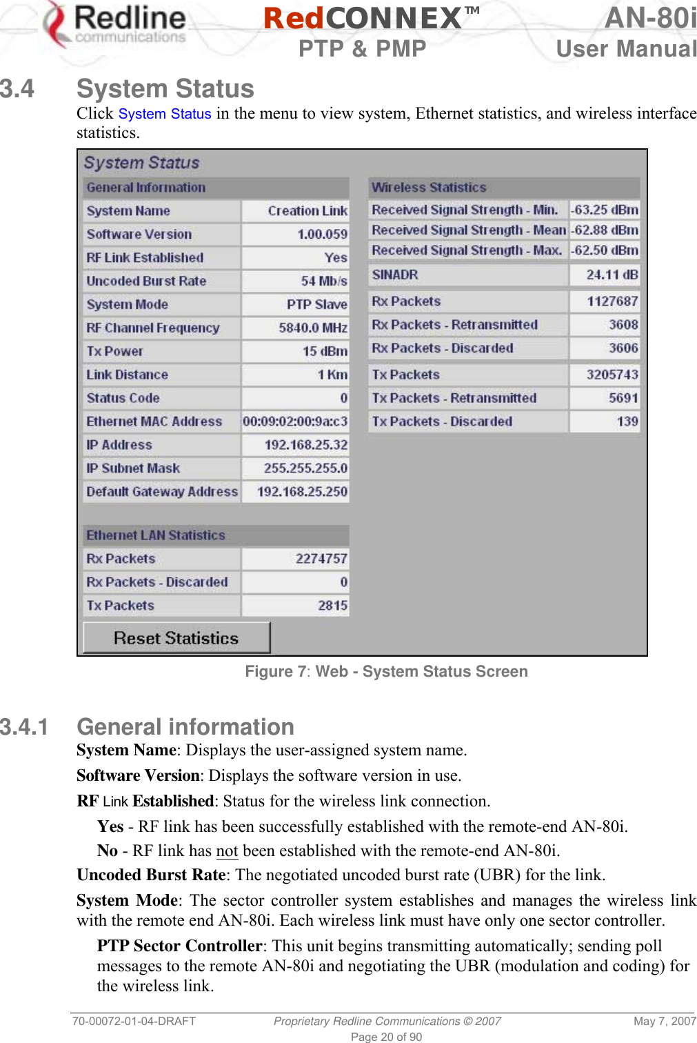
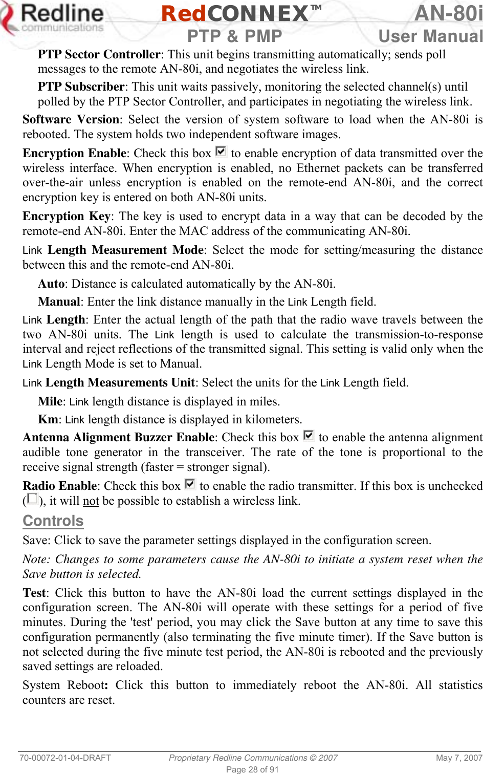
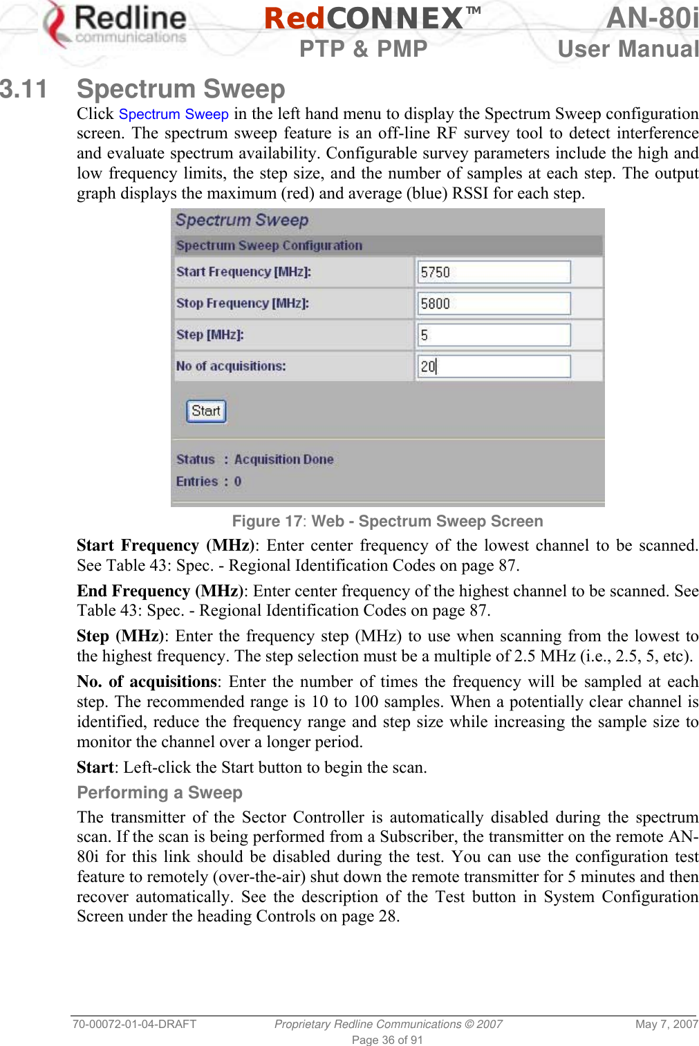
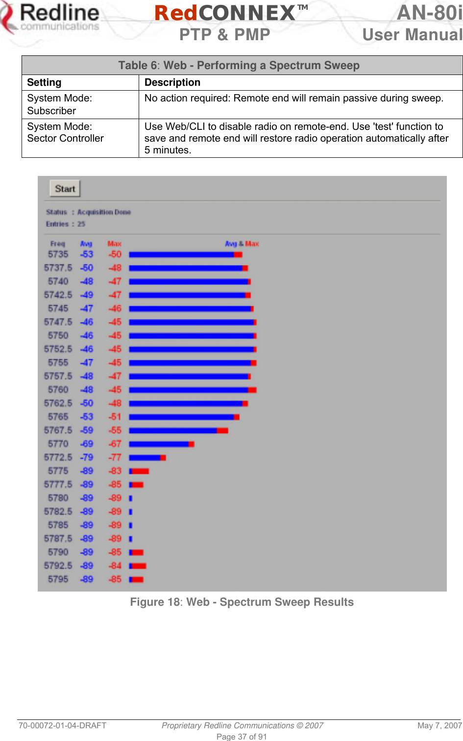
![RedCONNEXTM AN-80i PTP & PMP User Manual 70-00072-01-04-DRAFT Proprietary Redline Communications © 2007 May 7, 2007 Page 21 of 90 PTP Subscriber: This unit waits passively, monitoring the selected channel(s) until polled by the PTP Sector Controller. RF Channel Frequency: User-assigned RF channel. Tx Power: The current transmit power level. If ATPC is enabled, this value may be different than the Tx Power setting in the System Configuration screen. Link Distance [Miles or Km]: Distance between wireless systems. This may be the calculated or user-assigned distance (System Configuration screen). Status Code: Code indicating the condition of the AN-80i system. Status indications are specific for PMP and PTP operation. Ethernet MAC Address: System hardware address. This is also printed on a label affixed to the AN-80i. IP Address: User-assigned IP address of the AN-80i. IP Subnet Mask: User-assigned IP subnet mask. Default Gateway Address: User-assigned IP for the default router or gateway. 3.4.2 Ethernet LAN Statistics Rx Packets: Total packets received on the Ethernet port. Rx Packets: Discarded: Total valid Ethernet frames received on the Ethernet port that are discarded due to lack of buffer space. Tx Packets: Number of packets transmitted on the Ethernet port (including Ethernet frames and error correction bytes). 3.4.3 Wireless Statistics Received Signal Strength: Min: Minimum measured RSSI value. Received Signal Strength: Mean: Average measured RSSI value. Received Signal Strength: Max: Maximum measured RSSI value. SINADR: Average signal to interference, noise, and distortion ratio measured since the last screen refresh. Rx Packets: Total number of packets received over the wireless interface. Rx Packets: Retransmitted Number of packets received over the wireless interface that were retransmitted by the remote-end system (ARQ mechanism re-transmitting unacknowledged packets). Rx Packets - Discarded: Number of received packets discarded due to errors. Tx Packets: Number of packets transmitted over the wireless interface. Tx Packets - Retransmitted: Number of packets re-transmitted over the wireless interface (ARQ mechanism re-transmitting unacknowledged packets). Tx Packets: Discarded: Total number of packets transmitted over the wireless interface that were not acknowledged (discarded by remote-end due to errors). 3.4.4 Controls Reset Statistics: Click this button to zero the counters for the wireless and Ethernet LAN Statistics displayed on this page.](https://usermanual.wiki/Redline-Communications/AN80I.USERS-MANUAL-1/User-Guide-790830-Page-21.png)
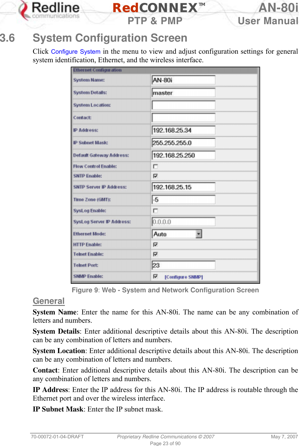
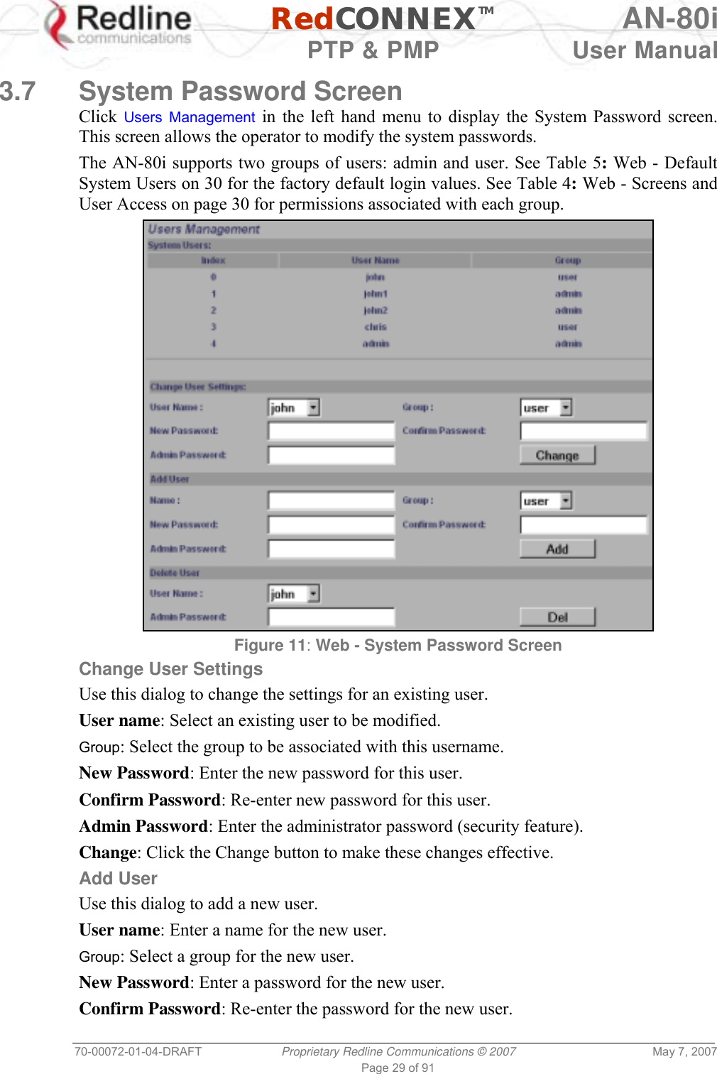
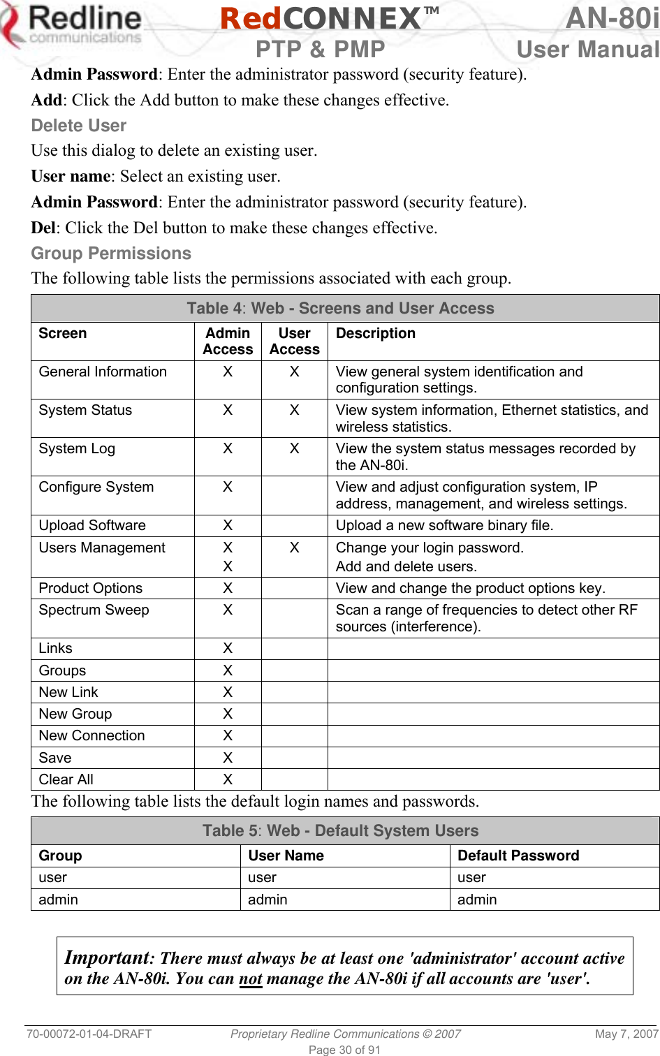
![RedCONNEXTM AN-80i PTP & PMP User Manual 70-00072-01-04-DRAFT Proprietary Redline Communications © 2007 May 7, 2007 Page 24 of 90 Default Gateway Address: Enter the IP address of the default gateway or router on the Ethernet segment connected to the AN-80i Ethernet port. Flow Control Enable: Check this box to enable flow control functions (802.3x) on the AN-80i Ethernet port. Enabling this feature allows the AN-80i to request Ethernet devices to pause transmissions during busy periods. SNTP Enable: Check this box to enable the SNTP protocol support. This feature allows AN-80i systems to time-stamp log messages using a network time server. When enabled, you must enter the network address of the SNTP server in the SNTP Server IP Address field. SNTP Server IP Address: Enter the network address of the SNTP server. Valid only when the SNTP Enable field is checked. Time Zone (GMT): Enter the hours offset from GMT for this time zone. Valid only when the SNTP Enable field is checked. Syslog Enable: Check this box to enable the Syslog protocol support. This feature allows AN-80i log messages to be saved in a central repository. When enabled, you must enter the network address of the Syslog server in the Syslog Server IP Address field. Syslog Server IP Address: Enter the network address of the Syslog server. Valid only when the Syslog Enable field is checked. Ethernet Mode: Select the operating mode of the Ethernet port. Auto - Auto-negotiate the speed connection speed. 10 - Operate at 10Base-T only. 100 - Operate at 100Base-T only. HD - Operate at half-duplex only. FD - Operate in full duplex only. Important: The auto-negotiate feature does not detect the speed and duplex of manually set Ethernet equipment. The auto-negotiate feature works correctly only when both communicating Ethernet devices are configured for auto-negotiate. Duplex mismatches may result in an unexpected loss of communications. HTTP Enable: Check this box to enable the HTTP (Web) interface. If the option is deselected, only CLI commands will be available. Telnet Enable: Check this box to enable a Telnet access (CLI) to the AN-80i. Refer to the CLI commands in CLI Interface on page 58. Telnet Port: Enter Telnet port address (default is 23). SNMP Enable: Check this box to enable the Simple Network Management Protocol (SNMP) agent. When this item is checked, clicking on the blue text [Configure SNMP] adjacent to the check box displays the SNMP Configuration screen.](https://usermanual.wiki/Redline-Communications/AN80I.USERS-MANUAL-1/User-Guide-790830-Page-24.png)
![RedCONNEXTM AN-80i PTP & PMP User Manual 70-00072-01-04-DRAFT Proprietary Redline Communications © 2007 May 7, 2007 Page 25 of 90 Figure 10: Web - Wireless Configuration Screen Wireless Configuration RF Freq. [MHz]: Enter the center frequency for the RF channel. This setting must be identical for both AN-80i systems operating as a wireless link. The options key controls channel availability. Refer to Table 43: Spec. - Regional Identification Codes on page 87 for available channels. Note: To minimize interference, the channel frequencies for AN-80i links operating in close proximity should be separated by a minimum of the channel size in use (to avoid overlapping bands). Auto scan: Check this box to enable the AN-80i PTP Subscriber to automatically scan available channels and locate the current operating frequency of the AN-80i PTP Sector Controller. Tx Power [dBm]: Enter the transmit power level (dBm). This setting is for the transceiver output only. The actual EIRP depends on the gain of the connected antenna (see](https://usermanual.wiki/Redline-Communications/AN80I.USERS-MANUAL-1/User-Guide-790830-Page-25.png)
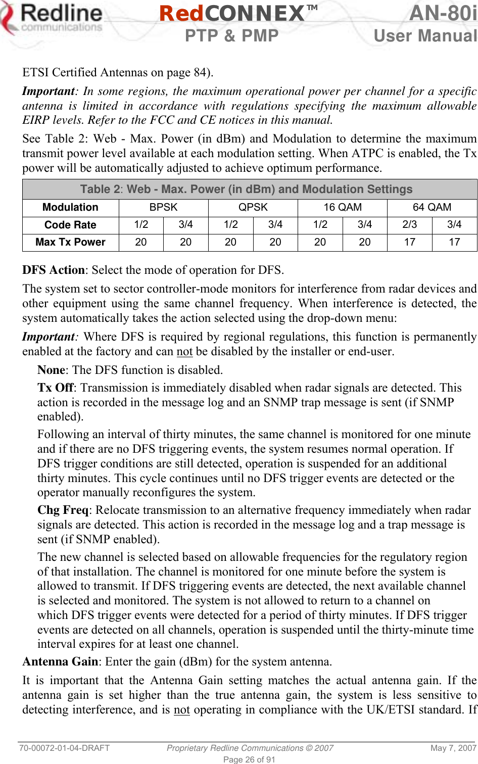
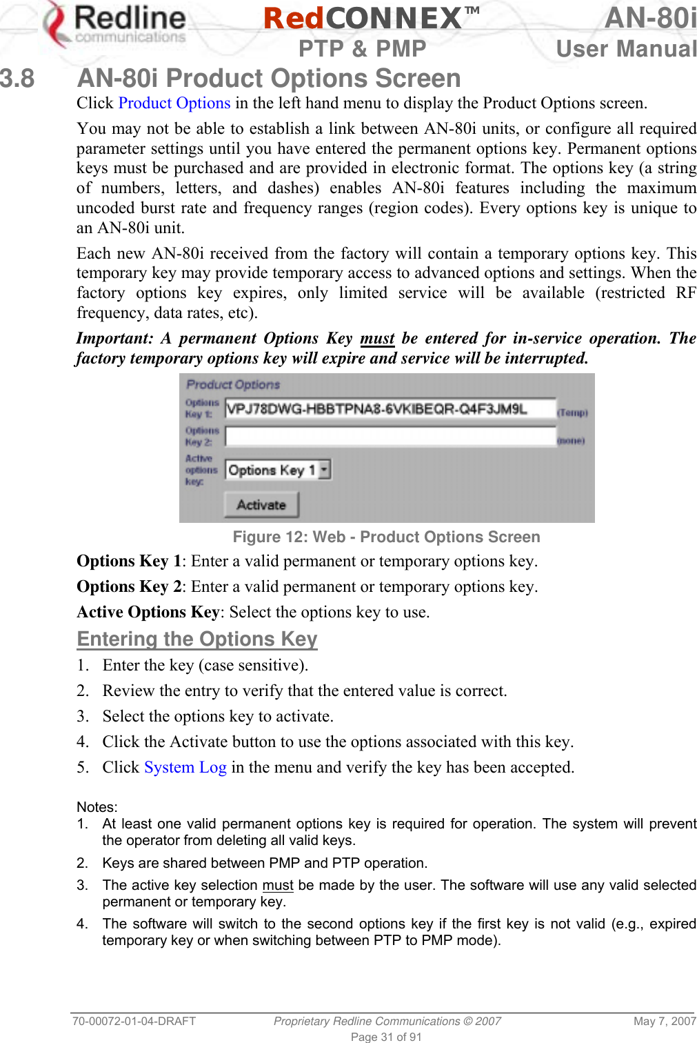
![RedCONNEXTM AN-80i PTP & PMP User Manual 70-00072-01-04-DRAFT Proprietary Redline Communications © 2007 May 7, 2007 Page 27 of 91 the antenna gain is set lower than the true antenna gain, the system is more sensitive to interference and this may result in false DFS triggers. ATPC Enable: Check this box to enable the AN-80i to monitor the received signal and request that the remote system adjustment its transmit level for optimum performance. The ATPC feature must be enabled on both AN-80i units. Adaptive Modulation: Check this box to enable the AN-80i to automatically adjust the transmission modulation and code settings to achieve the highest UBR that will operate with a packet error rate (PER at layer 2) of less than 1x10e-6. If the PER exceeds 1x10e-6, the AN-80i automatically adjusts the modulation and code settings downwards (i.e., from 16 QAM 3/4 to 16 QAM 1/2) to operate at a lower UBR where the PER is acceptable. When disabled, the modulation and code settings are entered manually using the Uncoded Burst Rate setting. See Table 2: Web - Max. Power (in dBm) and Modulation. Channel Width: Select the channel bandwidth. Refer to Table 43: Spec. - Regional Identification Codes on page 87 for available channel widths. Modulation Reduction Level: Enter the number of modulation/coding levels to step down during re-transmission of errored wireless packets. Each step down lowers the UBR. The level can be set from 0 to 7 (recommended value = 2). Uncoded Burst Rate [Mb/s]: Select the desired UBR for the link. If Adaptive Modulation is disabled, the AN-80i will transmit using only the specified settings. See Table 2: Web - Max. Power (in dBm) and Modulation. Ethernet Follows Wireless: Check this box to have the AN-80i disable and enable the Ethernet port function based on the status of the wireless interface. This feature allows switches and routers to trigger configuration changes based on changes to the AN-80i Ethernet port status. Disabled ( ): The AN-80i Ethernet port is always enabled. Enabled ( ): The Ethernet port status is controlled based on the status of the wireless interface. See the following table. Table 3: Web - Ethernet Status Indication Configuration Setting Wireless interface Status Ethernet Port Status Ethernet Follows Wireless Link Up Enabled Link Down Enabled Ethernet Follows Wireless Link Up Enabled Link Down Disabled Important: The Ethernet Follows Wireless setting affects all data and management traffic (HTTP, TELNET, and SNMP). When enabled, it is not possible to establish communications with the AN-80i using the Ethernet port while the wireless interface is down. If the wireless interface is down, the Ethernet Follows Wireless setting can only be set to 'off' by using the IP recovery procedure. See 6.2: Procedure to Reset AN-80i IP Address on page 75. System Mode: Set the operating mode for each AN-80i system.](https://usermanual.wiki/Redline-Communications/AN80I.USERS-MANUAL-1/User-Guide-790830-Page-27.png)