Redline Communications AN80I BROADBAND WIRELESS SYSTEM User Manual 70 00072 01 04 DRAFT
Redline Communications Inc. BROADBAND WIRELESS SYSTEM 70 00072 01 04 DRAFT
Contents
- 1. USERS MANUAL
- 2. USERS MANUAL 1
- 3. USERS MANUAL 2
USERS MANUAL 1
70-00072-01-04-DRAFT Proprietary Redline Communications © 2007 May 7, 2007
Page 1 of 90
RedCONNEXTM
AN-80i PTP & PMP
System
User Manual
RedCONNEXTM AN-80i
PTP & PMP User Manual
70-00072-01-04-DRAFT Proprietary Redline Communications © 2007 May 7, 2007
Page 2 of 90
Copyright Information
All rights reserved May 7, 2007. The information in this document is proprietary
to Redline Communications Inc. This document may not in whole or in part be
copied, reproduced, or reduced to any medium without prior consent, in writing,
from Redline Communications Incorporated.
Contact Information:
Redline Communications Inc.
302 Town Centre Blvd. Suite 100
Markham, ON
Canada L3R 0E8
Web site: http://www.redlinecommunications.com
Sales Inquiries:
North American nainfo@redlinecommunications.com
Toll-free sales 1-866-633-6669
International intlinfo@redlinecommunications.com
Support: www.redlinecommunications.com/support/support_portal.html
Document Control:
70-00072-01-04-AN-80i_User_Manual-20070507a.doc
Disclaimer
The statements, configurations, technical data, and recommendations in this document
are believed to be accurate and reliable, but are presented without express or implied
warranty. Additionally, Redline makes no representations or warranties, either expressed
or implied, regarding the contents of this product. Redline Communications shall not be
liable for any misuse regarding this product. The information in this document is subject
to change without notice.

RedCONNEXTM AN-80i
PTP & PMP User Manual
70-00072-01-04-DRAFT Proprietary Redline Communications © 2007 May 7, 2007
Page 3 of 90
TABLE OF CONTENTS
1 Important Safety & Service Notices....................................................... 9
1.1 Safety Warnings ........................................................................................ 9
1.2 Important Warning Symbols .................................................................... 10
1.3 Important Service Information ................................................................. 10
1.4 Lightning Protection................................................................................. 10
1.5 FCC & IC Notice...................................................................................... 11
1.6 UL Information......................................................................................... 12
1.7 Product Information ................................................................................. 12
2 System Overview................................................................................... 13
2.1 Ethernet Port ........................................................................................... 14
2.2 RF Port .................................................................................................... 14
2.3 Mounting Brackets................................................................................... 14
2.4 Grounding Connection ............................................................................ 14
2.5 Antenna Alignment .................................................................................. 15
2.6 Indoor Power Block (PoE Power Adapter) .............................................. 15
3 Web Interface - PTP............................................................................... 16
3.1 System Login........................................................................................... 16
3.2 System Menu .......................................................................................... 17
3.3 System Information ................................................................................. 18
General................................................................................................ 18
Ethernet............................................................................................... 19
Wireless............................................................................................... 19
3.4 System Status ......................................................................................... 20
3.4.1 General information ............................................................................. 20
3.4.2 Ethernet LAN Statistics........................................................................ 21
3.4.3 Wireless Statistics ............................................................................... 21
3.4.4 Controls ............................................................................................... 21
3.5 System Logs Screen ............................................................................... 22
3.6 System Configuration Screen.................................................................. 23
General................................................................................................ 23
Wireless Configuration ........................................................................ 25
Controls ............................................................................................... 28
3.7 System Password Screen ....................................................................... 29
3.8 AN-80i Product Options Screen .............................................................. 31
Entering the Options Key .................................................................... 31
3.9 Upload Software...................................................................................... 32
3.10 SNMP Settings Screen............................................................................ 33
3.10.1 Change SNMP Community ................................................................. 34
3.10.2 Change SNMP Trap Configuration...................................................... 35
3.11 Spectrum Sweep ..................................................................................... 36
4 PMP Operation....................................................................................... 38
4.1 Introduction.............................................................................................. 38
4.2 PMP Menu............................................................................................... 38

RedCONNEXTM AN-80i
PTP & PMP User Manual
70-00072-01-04-DRAFT Proprietary Redline Communications © 2007 May 7, 2007
Page 4 of 90
4.3 Functional Description............................................................................. 39
4.3.1 Overview.............................................................................................. 39
4.3.2 Minimum Setup Requirements ............................................................ 40
4.3.3 Packet Classification ........................................................................... 40
4.4 PMP Screens .......................................................................................... 41
4.4.1 Configuration Screen........................................................................... 41
Ethernet Settings................................................................................. 41
Wireless Settings................................................................................. 42
4.4.2 Link Screen.......................................................................................... 43
4.4.3 Group Screen ...................................................................................... 44
Group .................................................................................................. 44
Wireless traffic parameters.................................................................. 45
4.4.4 Connection Screen .............................................................................. 46
Connection Configuration.................................................................... 46
Wireless Traffic Parameters ................................................................ 47
4.5 Browse Screens ...................................................................................... 48
4.5.1 Links Screen........................................................................................ 48
4.5.2 Groups Screen .................................................................................... 49
4.5.3 Connections Screen ............................................................................ 50
4.6 Statistics Screens.................................................................................... 51
4.6.1 Link Statistics....................................................................................... 51
4.6.2 Group Statistics.................................................................................. 52
4.6.3 Connection Statistics ........................................................................... 53
4.6.4 System Status - PMP Wireless Statistics ............................................ 54
4.7 Quick Configuration Guide ...................................................................... 54
4.7.1 Configure Pass-Through Operation..................................................... 55
Step 1: Create New Link for Each Subscriber..................................... 55
Step 2: Create Single Pass-through Group......................................... 56
Step 3: Create Connections ................................................................ 56
Step 4: Save Configuration ................................................................. 56
4.7.2 VLAN Configuration............................................................................. 57
Step 1: Change Group to VLAN Tagged............................................. 57
Step 2: Change Connections to VLAN Tagged................................... 57
Step 3: Save Configuration ................................................................. 57
5 CLI Interface........................................................................................... 58
5.1 CLI Command Summary......................................................................... 58
5.2 Connecting with Telnet............................................................................ 59
5.3 CLI Command Set................................................................................... 60
5.3.1 Chgver ................................................................................................. 60
5.3.2 Clear .................................................................................................... 60
5.3.3 Del ....................................................................................................... 60
5.3.4 Enable ................................................................................................. 60
5.3.5 Get....................................................................................................... 61
5.3.6 Load..................................................................................................... 62
5.3.7 New ..................................................................................................... 63
5.3.8 Reset ................................................................................................... 63

RedCONNEXTM AN-80i
PTP & PMP User Manual
70-00072-01-04-DRAFT Proprietary Redline Communications © 2007 May 7, 2007
Page 5 of 90
5.3.9 Save .................................................................................................... 63
5.3.10 Script ................................................................................................... 63
5.3.11 Set ....................................................................................................... 64
5.3.12 Show.................................................................................................... 69
5.3.13 Snmpcommunity.................................................................................. 71
5.3.14 Snmptrap ............................................................................................. 72
5.3.15 Test...................................................................................................... 72
5.3.16 Upgrade............................................................................................... 72
5.3.17 User ..................................................................................................... 73
6 Diagnostics and Troubleshooting ....................................................... 74
6.1 Factory Default Settings .......................................................................... 74
6.2 Procedure to Reset AN-80i IP Address................................................... 75
6.3 Testing and Saving System Parameters ................................................. 76
6.3.1 CLI Interface ........................................................................................ 76
6.3.2 Web Interface ...................................................................................... 76
6.4 Log Messages ......................................................................................... 78
6.5 Status Codes........................................................................................... 81
6.5.1 PTP Status Codes ............................................................................... 81
6.5.2 PMP Status Codes .............................................................................. 81
7 Appendices............................................................................................ 82
7.1 AN-80i Technical Specifications.............................................................. 82
7.2 AN-80i PoE Specifications ...................................................................... 83
7.3 ETSI Certified Antennas.......................................................................... 84
7.3.1 5.4 GHz Radio: ETSI Certified Antennas ............................................ 84
7.3.2 5.8 GHz Radio: ETSI Certified Antennas ............................................ 84
7.4 FCC & IC Certified Antennas .................................................................. 85
7.4.1 5.4 GHz Radio: FCC & IC Certified Antennas ..................................... 85
7.4.2 5.8 GHz Radio: FCC & IC Certified Antennas ..................................... 85
7.5 Regional Codes....................................................................................... 87
7.6 Glossary Of Terms .................................................................................. 88

RedCONNEXTM AN-80i
PTP & PMP User Manual
70-00072-01-04-DRAFT Proprietary Redline Communications © 2007 May 7, 2007
Page 6 of 90
LIST OF TABLES
Table 1: FCC & IC RF Recommended Safe Separation Distances .................... 11
Table 2: Web - Max. Power (in dBm) and Modulation Settings........................... 26
Table 3: Web - Ethernet Status Indication .......................................................... 27
Table 4: Web - Screens and User Access .......................................................... 30
Table 5: Web - Default System Users................................................................. 30
Table 6: Web - Performing a Spectrum Sweep................................................... 37
Table 7: PMP - Basic Pass-Through Group Settings.......................................... 40
Table 8: PMP - Packet Classification .................................................................. 40
Table 9: PMP Maximum Achievable UBR........................................................... 43
Table 10: PMP - Basic Pass-Through Group Configuration Settings.................. 56
Table 11: CLI - Command Summary .................................................................. 58
Table 12: CLI - Root Mode Commands .............................................................. 59
Table 13: CLI - chgver......................................................................................... 60
Table 14: CLI - clear............................................................................................ 60
Table 15: CLI - del............................................................................................... 60
Table 16: CLI - enable......................................................................................... 60
Table 17: CLI - get .............................................................................................. 61
Table 18: CLI - load............................................................................................. 62
Table 19: CLI - new............................................................................................. 63
Table 20: CLI - reset ........................................................................................... 63
Table 21: CLI - save............................................................................................ 63
Table 22: CLI - script........................................................................................... 63
Table 23: CLI - set............................................................................................... 64
Table 24: CLI - show ........................................................................................... 69
Table 25: CLI - snmpcommunity ......................................................................... 71
Table 26: CLI - snmptrap .................................................................................... 72
Table 27: CLI - test.............................................................................................. 72
Table 28: CLI - upgrade ...................................................................................... 72
Table 29: CLI - user ............................................................................................ 73
Table 30: Diag. - Factory Default Settings .......................................................... 74
Table 31: Diag. - Web Interface Diagnostics....................................................... 77
Table 32: Diag. - System Log Messages ............................................................ 78
Table 33: Diag. - PMP Status Code Bits ............................................................. 81
Table 34: Diag. - PMP Status Codes .................................................................. 81
Table 35: Diag. - PMP Status Codes .................................................................. 81
Table 36: Spec. - AN-80i Technical Specifications ............................................. 82
Table 37: Spec. - AN-80i PoE Specifications...................................................... 83
Table 38: Spec. - ETSI Certified Antennas: 5.4 GHz Operation ......................... 84
Table 39: Spec. - ETSI Certified Antennas: 5.8 GHz Operation ......................... 84
Table 40: Spec. - FCC & IC Certified Antennas: 5.4 GHz Operation.................. 85
Table 41: Spec. - FCC & IC Certified Antennas: 5.8 GHz Operation.................. 85
Table 42: Spec. - FCC & IC Certified Antennas: 5.8 GHz PMP Operation ......... 86
Table 43: Spec. - Regional Identification Codes ................................................. 87

RedCONNEXTM AN-80i
PTP & PMP User Manual
70-00072-01-04-DRAFT Proprietary Redline Communications © 2007 May 7, 2007
Page 7 of 90
Table 44: Spec. - Glossary.................................................................................. 88

RedCONNEXTM AN-80i
PTP & PMP User Manual
70-00072-01-04-DRAFT Proprietary Redline Communications © 2007 May 7, 2007
Page 8 of 90
LIST OF FIGURES
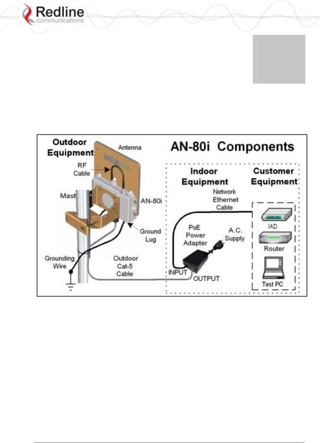
Figure 1: Intro - AN-80i Components .................................................................. 13
Figure 2: Intro - AN-80i with Integrated Antenna................................................. 14
Figure 3: Intro - Indoor Power-over-Ethernet (PoE) Module ............................... 15
Figure 4: Web - Login Screen ............................................................................. 16
Figure 5: Web - System Menu ............................................................................ 17
Figure 6: Web - General Information Screen ...................................................... 18
Figure 7: Web - System Status Screen............................................................... 20
Figure 8: Web - System Log Messages .............................................................. 22
Figure 9: Web - System and Network Configuration Screen............................... 23
Figure 10: Web - Wireless Configuration Screen................................................ 25
Figure 11: Web - System Password Screen ....................................................... 29
Figure 12: Web - Product Options Screen .......................................................... 31
Figure 13: Web - Upload Software Screen ......................................................... 32
Figure 14: Web - SNMP Configuration Screen ................................................... 33
Figure 15: Web - SNMP Community Configuration Screen ................................ 34
Figure 16: Web - SNMP Trap Configuration Screen........................................... 35
Figure 17: Web - Spectrum Sweep Screen......................................................... 36
Figure 18: Web - Spectrum Sweep Results ........................................................ 37
Figure 19: PMP - Main Menu .............................................................................. 38
Figure 20: PMP - Basic Pass-through Group Configuration................................ 39
Figure 21: PMP - VLAN Tagged Traffic Example ............................................... 39
Figure 22: PMP - Ethernet Settings .................................................................... 41
Figure 23: PMP - Wireless Settings .................................................................... 42
Figure 24: PMP - Link Configuration Screen....................................................... 43
Figure 25: PMP - Group Configuration Screen ................................................... 44
Figure 26: PMP - Connection Configuration Screen ........................................... 46
Figure 27: PMP - Links Browse Screen .............................................................. 48
Figure 28: PMP - Groups Browse Screen........................................................... 49
Figure 29: PMP - Connections Browse Screen................................................... 50
Figure 30: PMP - Link Statistics Screen.............................................................. 51
Figure 31: PMP - Group Statistics Screen .......................................................... 52
Figure 32: PMP - Connection Statistics Screen .................................................. 53
Figure 33: PMP - System Status Screen ............................................................ 54
Figure 34: PMP - Pass-through Only Deployment .............................................. 55
Figure 35: CLI - Connecting via Telnet ............................................................... 59
Figure 36: CLI - Recovering Lost IP Address...................................................... 75
Figure 37: Diag - Saving Parameters in NVRAM ................................................ 76

RedCONNEXTM AN-80i
PTP & PMP User Manual
70-00072-01-04-DRAFT Proprietary Redline Communications © 2007 May 7, 2007
Page 9 of 90
Chapter
1
1
1
I
Im
mp
po
or
rt
ta
an
nt
t
S
Sa
af
fe
et
ty
y
&
&
S
Se
er
rv
vi
ic
ce
e
N
No
ot
ti
ic
ce
es
s
1.1 Safety Warnings
1. PoE power adapter caution:
PoE Power adapter Caution
Warning to Service Personnel: 48 VDC
Connecting customer premises Ethernet equipment directly to the 'OUTPUT'
connector on the AN-80i Power-over-Ethernet power adapter may damage
customer network interface equipment. Customer equipment including
personal computers, routers, etc., must only be connected to the 'INPUT' port
on the PoE unit. Only the outdoors Ethernet interface cable to the AN-80i can
be safely connected to the 'OUTPUT' connector.
2. Installation of the system must be contracted to a professional installer.
3. Read this user manual and follow all operating and safety instructions.
4. Keep all product information for future reference.
5. The power requirements are indicated on the product-marking label. Do not exceed
the described limits.
6. Use only a damp cloth for cleaning. Do not use liquid or aerosol cleaners. Disconnect
the power before cleaning.
7. Disconnect power when unit is stored for long periods.
8. The AN-80i must not be located near power lines or other electrical power circuits.
9. The system must be properly grounded to protect against power surges and
accumulated static electricity. It is the user’s responsibility to install this device in
accordance with the local electrical codes: correct installation procedures for
grounding the AN-80i, mast, lead-in wire and discharge unit, location of discharge
unit, size of grounding conductors and connection requirements for grounding
electrodes.

RedCONNEXTM AN-80i
PTP & PMP User Manual
70-00072-01-04-DRAFT Proprietary Redline Communications © 2007 May 7, 2007
Page 10 of 90
1.2 Important Warning Symbols
The following symbols may be encountered during installation or troubleshooting. These
warning symbols mean danger. Bodily injury may result if you are not aware of the safety
hazards involved in working with electrical equipment and radio transmitters. Familiarize
yourself with standard safety practices before continuing.
Electro-Magnetic Radiation High Voltage
1.3 Important Service Information
1. Refer all repairs to qualified service personnel. Do not remove the covers or modify
any part of this device, as this voids the warranty.
2. Locate the serial numbers and record these on your registration card for future
reference. Use the space below to affix serial number stickers. Also, record the MAC
address located on the AN-80i.
1.4 Lightning Protection
WARNING: The following notes are general recommendations for the system. The
wireless equipment should be installed by a qualified professional installer who must
follow local and national codes for electrical grounding and safety. Failure to meet safety
requirements and/or use of non-standard practices and procedures could result in personal
injury and damage to equipment. A direct lightning strike may cause serious damage
even if these guidelines are followed.
All outdoor wireless equipment is susceptible to lightning damage from a direct hit or
induced current from a near strike. Lightning protection and grounding practices in local
and national electrical codes serve to minimize equipment damage, service outages, and
serious injury. Reasons for lightning damage are summarized as:
a) Poorly grounded antenna sites that can conduct high lightning strike energy into
equipment.
b) Lack of properly installed lightning protection equipment that can cause equipment
failures from lightning induced currents.
A lighting protection system provides a means by which the energy may enter earth
without passing through and damaging parts of a structure. A lightning protection system
does not prevent lightning from striking; it provides a means for controlling it and
preventing damage by providing a low resistance path for the discharge of energy to
travel safely to ground. Improperly grounded connections are also a source of noise that
can cause sensitive equipment to malfunction.
A good grounding system disperses most of the surge energy from a lightning strike away
from the building and equipment. The remaining energy on the Ethernet cable shield and
center conductor can be directed safely to ground by using a lightning arrestor in series
with the cable.
If you have determined that it is appropriate to install lightning protection for your
system, the following general industry practices are provided as a guideline only:
RedCONNEXTM AN-80i
PTP & PMP User Manual
70-00072-01-04-DRAFT Proprietary Redline Communications © 2007 May 7, 2007
Page 11 of 90
1. The AC wall outlet ground for the indoor POE adapter should be connected to the
building grounding system. as the AN-80i lightning protectors.
2. Install a lightning arrestor in series with the Ethernet cable at the point of entry to the
building. The grounding wire should be connected to the same termination point used
for the tower or mast.
3. Install a lightning arrestor in series with the Ethernet cable as close to the AN-80i as
practical. The grounding wire should be connected to the same termination point used
for the tower or mast.
4. Provide direct grounding from the AN-80i, the mounting bracket, the antenna, and the
Ethernet cable surge protection to the same ground bus on the building. Use the
grounding screws provided for terminating the ground wires.
1.5 FCC & IC Notice
1. The Model AN-80i and its antenna must be professionally installed.
2. WARNING -- FCC & IC RF Exposure Warnings
To satisfy FCC and IC RF exposure requirements for RF transmitting devices, the
following distances should be maintained between the antenna of this device and
persons during device operation:
Table 1: FCC & IC RF Recommended Safe Separation Distances
Frequency Application Separation Distance
5.4 GHz PTP 20 centimeters or more
5.8 GHz PTP 310 centimeters or more
5.8 GHz PMP 20 centimeters or more
To ensure compliance, operation at closer than these distances is not recommended.
The antenna used for this transmitter must not be collocated in conjunction with any
other antenna or transmitter.
3. High power radars are allocated as primary users (meaning they have priority) of
5250-5350 MHz and 5650-5850 MHz and these radars could cause interference
and/or damage to LE-LAN devices.
4. FCC Information to Users @ FCC 15.21 & 15.105:
This equipment has been tested and found to comply with the limits for a Class A
digital device, pursuant to Part 15 of the FCC Rules. These limits are designed to
provide reasonable protection against harmful interference when the equipment is
operated in a commercial environment. This equipment generates, uses, and can
radiate radio frequency energy and, if not installed and used in accordance with the
instruction manual, may cause harmful interference to radio communications.
5. Warning: Changes or modifications not expressly approved by Redline
Communications could void the user’s authority to operate the equipment.
6. Refer to FCC & IC Certified Antennas beginning on page 85 for a list of certified
antennas.
7. Where DFS is required by regional regulations, this function is permanently enabled
at the factory and can not be disabled by the installer or end-user.

RedCONNEXTM AN-80i
PTP & PMP User Manual
70-00072-01-04-DRAFT Proprietary Redline Communications © 2007 May 7, 2007
Page 12 of 90
1.6 UL Information
1. The suitability of the supplied Ethernet cable is subject to the approval of Authority
Having Jurisdiction and must comply with the local electrical code.
2. The equipment must be properly grounded according with NEC and other local safety
code and building code requirements
3. To meet the over-voltage safety requirements on the telecommunications cables, a
minimum 26 AWG telecommunication line cord must be used.
4. "Pour être en conformance avec les exigences finies de sûreté de sur-tension sur les
câbles de télécommunications un fil de télécommunication ayant un caliber minimum
de 26 AWG doit être utilisé."
5. Reminder to all the BWA system installers: Attention to Section 820-40 of the NEC
which provides guidelines for proper grounding and, in particular, specifies that the
cable ground shall be connected to the grounding system of the building, as close to
the point of cable entry as is practical.
6. AN-80i must be installed in compliance with relevant articles in National Electrical
Code-NEC (and equivalent Canadian Code-CEC) including referenced articles 725,
800 and 810 in NEC.
7. RF coaxial cable connecting an antenna to AN-80i must comply with the local
electrical code.
1.7 Product Information
Use the following table to record important system information:
Product Information
AN-80i SN: MAC Address
PoE SN: Model #:
Antenna Model No.: Antenna SN:
Serial Number Stickers
RedCONNEXTM AN-80i
PTP & PMP User Manual
70-00072-01-04-DRAFT Proprietary Redline Communications © 2007 May 7, 2007
Page 13 of 90
Chapter
2
2
2
S
Sy
ys
st
te
em
m
O
Ov
ve
er
rv
vi
ie
ew
w
The Access Node 80i system is manufactured by Redline Communications -- a world
leader in design and production of Broadband Fixed Wireless (BFW) systems.
Figure 1: Intro - AN-80i Components
The AN-80i is a high-performance, high-speed wireless Ethernet bridge for use in a
commercial, industrial, business, or government environment. The system can operate
with a 5.4 GHz radio installed or a 5.8 GHz radio installed using a time division
duplexing (TDD) RF transceiver to transmit and receive on the same RF channel. The
main AN-80i features include: advanced technologies to address inter-cell interference,
enhanced security features through a proprietary over-the-air encryption scheme, and
Automatic Transmitter Power Control (ATPC) to automatically achieve and maintain
optimum performance.
The AN-80i outdoor unit is housed in a weatherproof aluminum alloy case. The outdoor
unit can be used with a selection of available external antennas. When equipped with a
narrow beam antenna, the AN-80i supports long-range operations of over 50 miles (80
km) in clear line of sight (LOS) conditions. An indoor PoE power adapter provides
operational power for the AN-80i and connection to the Ethernet network.
RedCONNEXTM AN-80i
PTP & PMP User Manual
70-00072-01-04-DRAFT Proprietary Redline Communications © 2007 May 7, 2007
Page 14 of 90
Each wireless link requires two AN-80i units. One AN-80i is configured as the PTP
Sector Controller and controls the wireless link. This function is transparent to all
Ethernet operations. The sector controller AN-80i uses a scheduled request/grant
mechanism to arbitrate requests for bandwidth from the remote unit -- providing non
contention-based traffic with predictable transmission characteristics. The second AN-80i
operates as a PTP Subscriber under control of the sector controller unit.
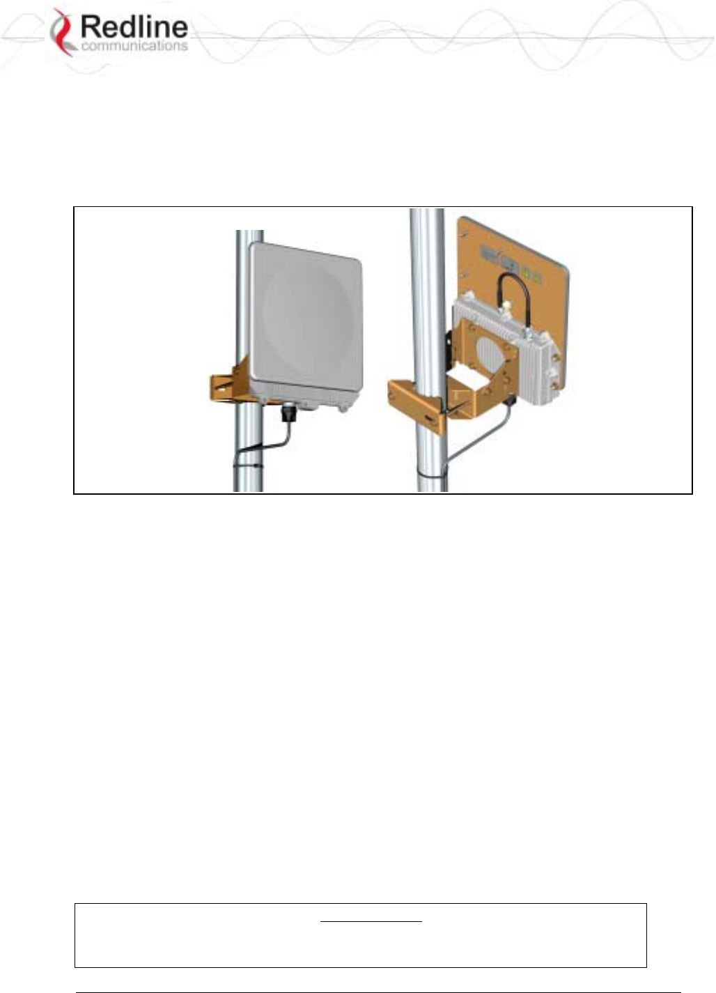
Figure 2: Intro - AN-80i with Integrated Antenna
2.1 Ethernet Port
The AN-80i receives DC power and exchanges data with the indoor network through the
Ethernet port. The AN-80i Ethernet port connects to the PoE Adapter using a
weatherproof Cat. 5e Ethernet cable. The Ethernet port is a female RJ-45 connector.
2.2 RF Port
The RF port is used to sending and receive RF signal to/from the antenna. A short coaxial
cable is provided to connect the transceiver to an external antenna. The RF port is a
female N-type connector.
2.3 Mounting Brackets
There are two mounting brackets available for the AN-80i. The lightweight (two-point)
antenna bracket provides convenient mounting of one foot flat panel antennas. The
heavy-duty (four-point) antenna mounting bracket is available for mounting two foot flat
panel and parabolic antennas.
2.4 Grounding Connection
A ground-lug is provided on the AN-80i chassis. Use this connection to terminate a
grounding wire.
Important: Correct grounding is very important for safe operation of wireless
equipment. Ensure that all grounding connections are made in accordance with
local and national standards.
RedCONNEXTM AN-80i
PTP & PMP User Manual
70-00072-01-04-DRAFT Proprietary Redline Communications © 2007 May 7, 2007
Page 15 of 90
2.5 Antenna Alignment
The AN-80i includes an audible antenna alignment tool to assist in pointing the antenna
for maximum signal strength. The signal will sound infrequently when a low signal is
detected, and more often as the signal strength increases. The audible signal is enabled
and disabled through the user interface:
Web: See Antenna Alignment Buzzer Enable on page 23
Telnet: See buzzer in CLI Set commands on page 64
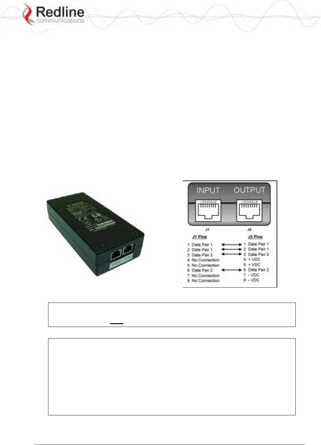
2.6 Indoor Power Block (PoE Power Adapter)
The PoE power adapter provides operational power and connection to a local Ethernet
network. The power block provides two Ethernet interfaces:
INPUT: The 10/100Base-T Ethernet port (RJ-45) for connection to local network
equipment.
OUTPUT: The 10/100Base-T Ethernet port (RJ-45) port to carry signal and power to
the AN-80i.
Figure 3: Intro - Indoor Power-over-Ethernet (PoE) Module
Important: PoE Adapter Type
Use the AN-80i only with CINCON PoE Adapter Model TR60A-POE-L.
PoE Power Adapter Caution
Warning to Service Personnel: 48 VDC
Connecting customer premises Ethernet equipment directly to the 'OUTPUT'
connector on the AN-80i Power-over-Ethernet power adapter may damage
customer network interface equipment. Customer equipment including
personal computers, routers, etc., must only be connected to the 'INPUT' port
on the PoE unit. Only the outdoor Ethernet interface cable to the AN-80i can
be safely connected to the 'OUTPUT' connector.
RedCONNEXTM AN-80i
PTP & PMP User Manual
70-00072-01-04-DRAFT Proprietary Redline Communications © 2007 May 7, 2007
Page 16 of 90
Chapter
3
3
3
W
We
eb
b
I
In
nt
te
er
rf
fa
ac
ce
e
-
-
P
PT
TP
P
The Web Interface provides all required settings and statistics necessary to configure and
monitor the operation of the AN-80i using a standard web browser. An operator can
access and control the AN-80i remotely from any geographical location with HTTP
connectivity to that unit.
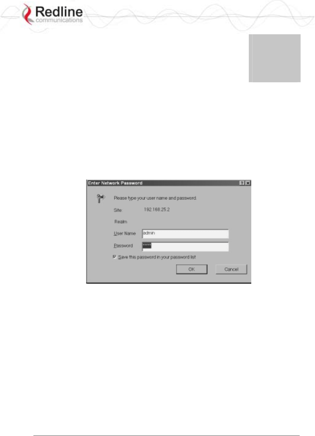
3.1 System Login
On the PC, open a browser (Internet Explorer 6 or higher recommended). For new
systems, enter the default IP address (192.168.25.2). The following dialog should be
displayed:
Figure 4: Web - Login Screen
Login to the AN-80i using your user name and password. See Table 5: Web - Default
System Users on page 30 for the factory default usernames and passwords.
If the IP address, username and/or password have been modified since installation,
contact the network administrator to determine the current settings. If the IP address, or
the user name and password cannot be determined. See Procedure to Reset AN-80i IP
Address on page 75.
RedCONNEXTM AN-80i
PTP & PMP User Manual
70-00072-01-04-DRAFT Proprietary Redline Communications © 2007 May 7, 2007
Page 17 of 90
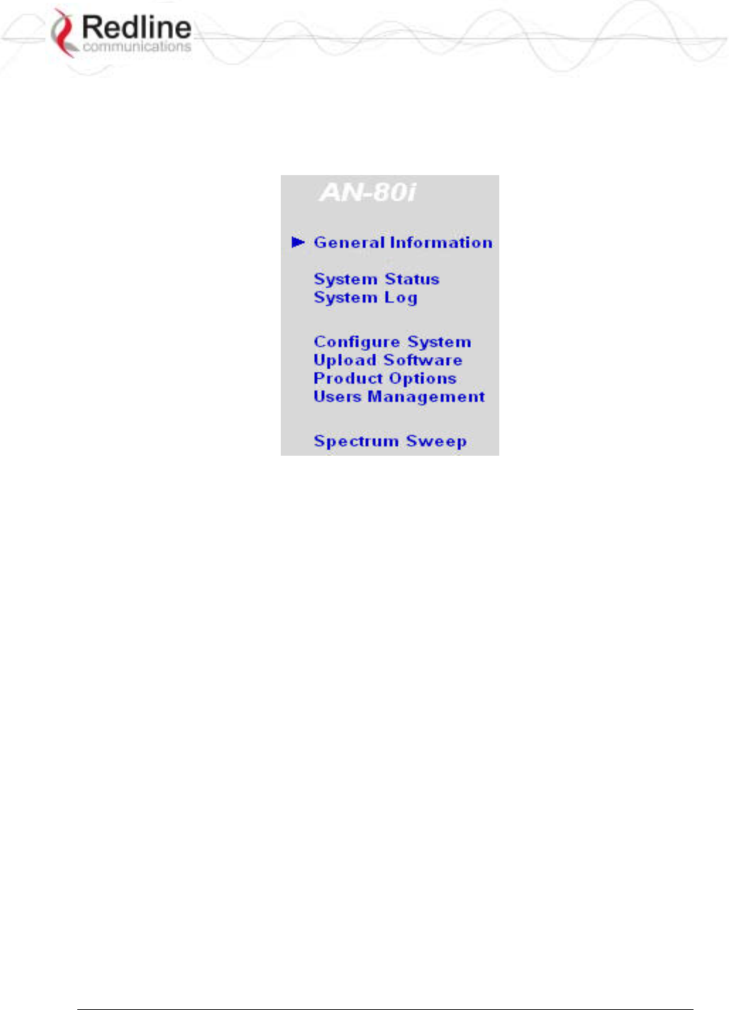
3.2 System Menu
Following a successful login, the General Information screen is displayed. On the left is a
menu of all available screens. Point and click on the blue text of the menu to display that
screen.
Figure 5: Web - System Menu
The administrator (admin) has unrestricted access to all screens. All other users have
viewing access only. See 3.7: System Password Screen on page 29 for details.
RedCONNEXTM AN-80i
PTP & PMP User Manual
70-00072-01-04-DRAFT Proprietary Redline Communications © 2007 May 7, 2007
Page 18 of 90
3.3 System Information
Click General Information to view the system overview screen (read-only). Refer to the
System Configuration screen for information about changing these settings.
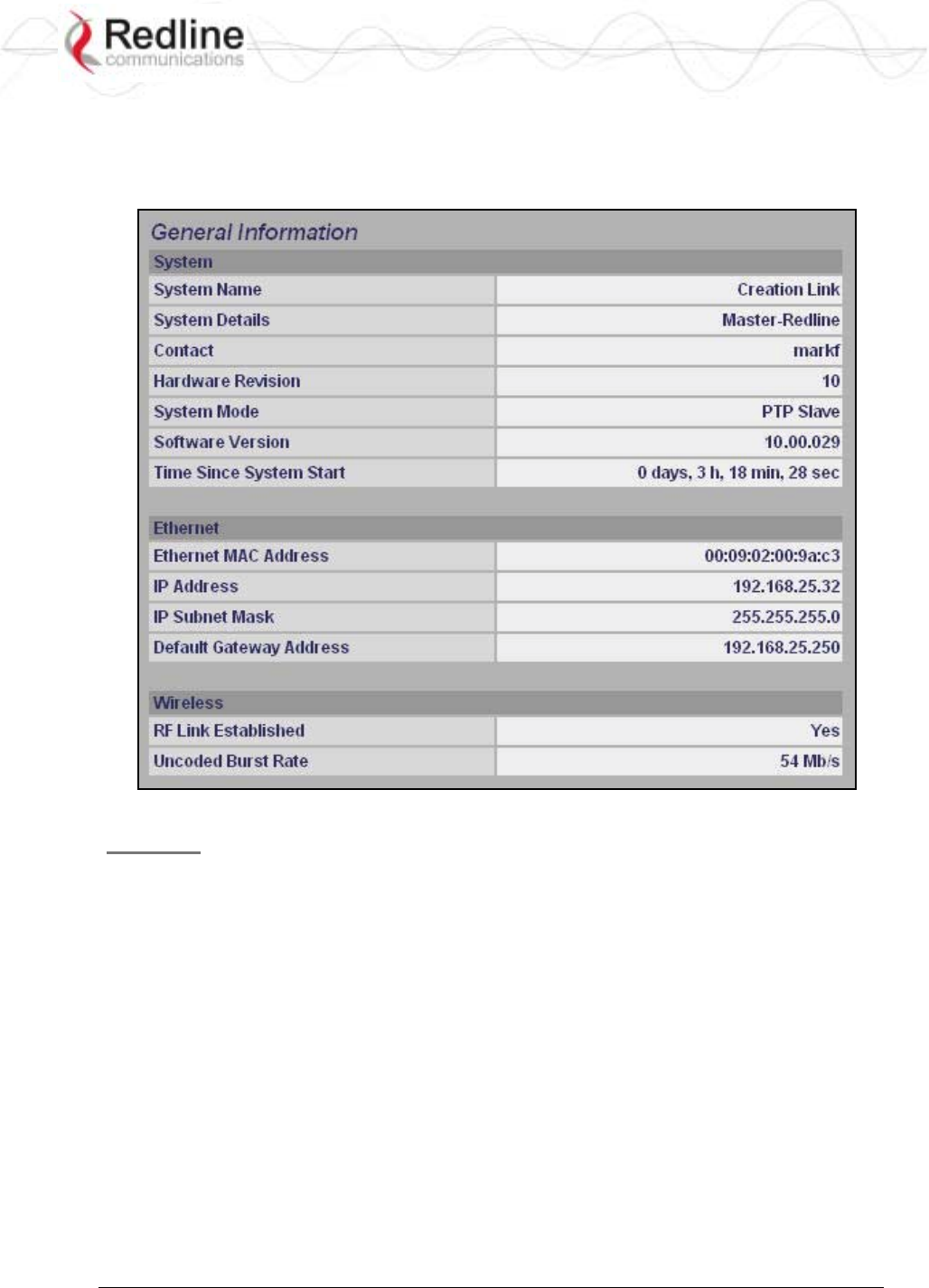
Figure 6: Web - General Information Screen
General
System Name: User-assigned name for this AN-80i.
System Details: User-assigned system details information.
Contact: User-assigned contact information.
Hardware Version: Displays the hardware version of the AN-80i.
System Mode: The system designated as sector controller establishes and manages the
bi-directional data link with a remote end AN-80i. Only one system in a wireless link
must be set for Sector Controller mode.
PTP Master: AN-80i begins transmitting automatically, sends poll messages to locate
the remote AN-80i Slave, and negotiates operating settings for the link.
PTP Slave: AN-80i waits passively, monitoring the selected channel(s) until polled by
the PTP Master.
Software Version: Displays the software version in use.
Time Since System Start: Time since the system was last reset or powered-on.

RedCONNEXTM AN-80i
PTP & PMP User Manual
70-00072-01-04-DRAFT Proprietary Redline Communications © 2007 May 7, 2007
Page 19 of 90
Ethernet
Ethernet MAC Address: Hardware (MAC) address of this AN-80i. This address is also
recorded on a label on the AN-80i chassis.
IP Address: User-assigned IP address of this AN-80i.
IP Subnet Mask: User assigned IP subnet mask.
Default Gateway Address: User-assigned IP address of the default router or gateway.
Wireless
RF Link Established: Status of the wireless link.
Yes - RF link successfully established with remote-end AN-80i.
No - RF link not established with remote-end AN-80i.
Uncoded Burst Rate: The current uncoded burst rate for the link.
RedCONNEXTM AN-80i
PTP & PMP User Manual
70-00072-01-04-DRAFT Proprietary Redline Communications © 2007 May 7, 2007
Page 20 of 90
3.4 System Status
Click System Status in the menu to view system, Ethernet statistics, and wireless interface
statistics.
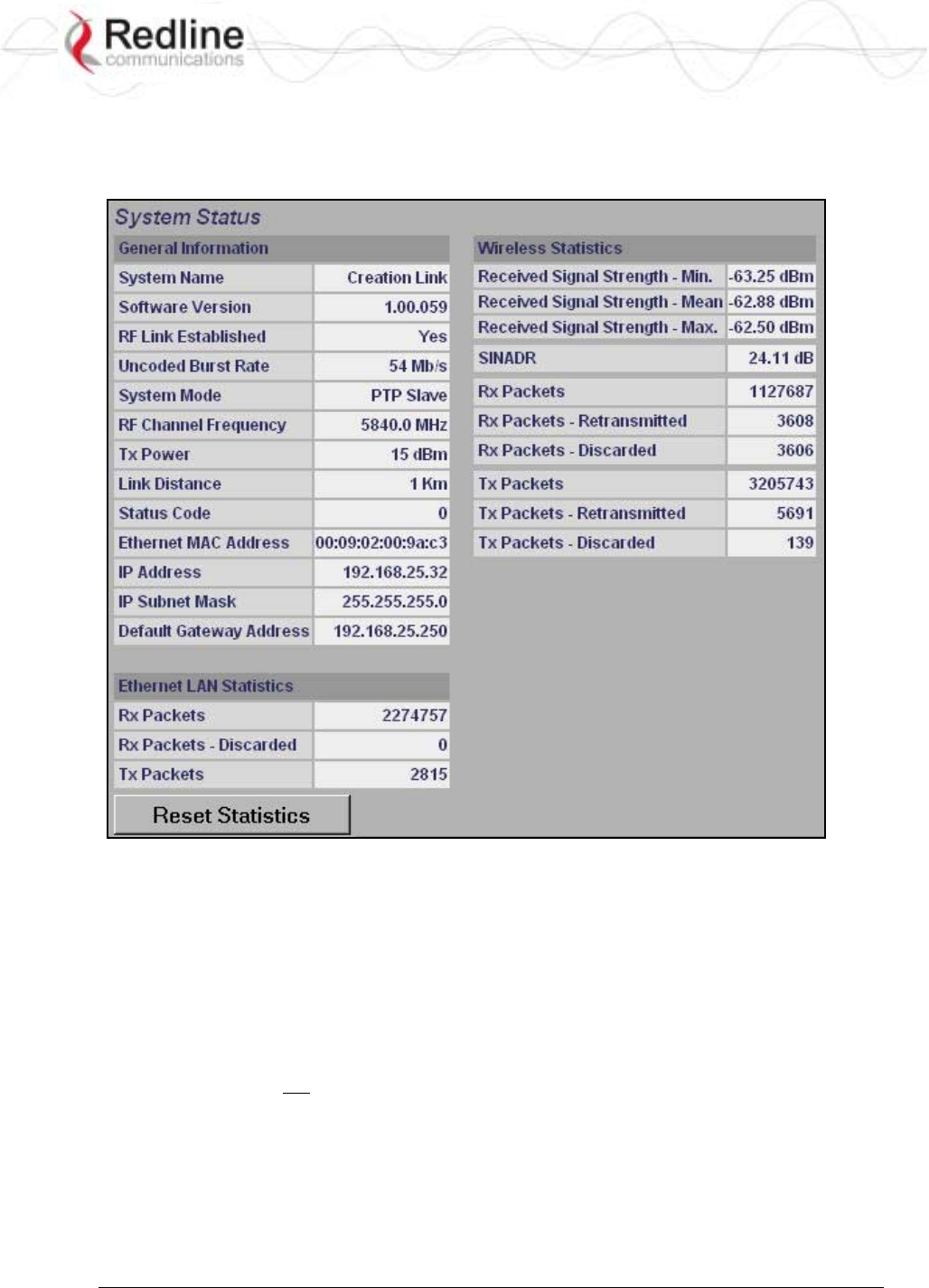
Figure 7: Web - System Status Screen
3.4.1 General information
System Name: Displays the user-assigned system name.
Software Version: Displays the software version in use.
RF Link Established: Status for the wireless link connection.
Yes - RF link has been successfully established with the remote-end AN-80i.
No - RF link has not been established with the remote-end AN-80i.
Uncoded Burst Rate: The negotiated uncoded burst rate (UBR) for the link.
System Mode: The sector controller system establishes and manages the wireless link
with the remote end AN-80i. Each wireless link must have only one sector controller.
PTP Sector Controller: This unit begins transmitting automatically; sending poll
messages to the remote AN-80i and negotiating the UBR (modulation and coding) for
the wireless link.

RedCONNEXTM AN-80i
PTP & PMP User Manual
70-00072-01-04-DRAFT Proprietary Redline Communications © 2007 May 7, 2007
Page 21 of 90
PTP Subscriber: This unit waits passively, monitoring the selected channel(s) until
polled by the PTP Sector Controller.
RF Channel Frequency: User-assigned RF channel.
Tx Power: The current transmit power level. If ATPC is enabled, this value may be
different than the Tx Power setting in the System Configuration screen.
Link Distance [Miles or Km]: Distance between wireless systems. This may be the
calculated or user-assigned distance (System Configuration screen).
Status Code: Code indicating the condition of the AN-80i system. Status indications are
specific for PMP and PTP operation.
Ethernet MAC Address: System hardware address. This is also printed on a label affixed
to the AN-80i.
IP Address: User-assigned IP address of the AN-80i.
IP Subnet Mask: User-assigned IP subnet mask.
Default Gateway Address: User-assigned IP for the default router or gateway.
3.4.2 Ethernet LAN Statistics
Rx Packets: Total packets received on the Ethernet port.
Rx Packets: Discarded: Total valid Ethernet frames received on the Ethernet port that are
discarded due to lack of buffer space.
Tx Packets: Number of packets transmitted on the Ethernet port (including Ethernet frames
and error correction bytes).
3.4.3 Wireless Statistics
Received Signal Strength: Min: Minimum measured RSSI value.
Received Signal Strength: Mean: Average measured RSSI value.
Received Signal Strength: Max: Maximum measured RSSI value.
SINADR: Average signal to interference, noise, and distortion ratio measured since the last
screen refresh.
Rx Packets: Total number of packets received over the wireless interface.
Rx Packets: Retransmitted Number of packets received over the wireless interface that
were retransmitted by the remote-end system (ARQ mechanism re-transmitting
unacknowledged packets).
Rx Packets - Discarded: Number of received packets discarded due to errors.
Tx Packets: Number of packets transmitted over the wireless interface.
Tx Packets - Retransmitted: Number of packets re-transmitted over the wireless interface
(ARQ mechanism re-transmitting unacknowledged packets).
Tx Packets: Discarded: Total number of packets transmitted over the wireless interface that
were not acknowledged (discarded by remote-end due to errors).
3.4.4 Controls
Reset Statistics: Click this button to zero the counters for the wireless and Ethernet LAN
Statistics displayed on this page.
RedCONNEXTM AN-80i
PTP & PMP User Manual
70-00072-01-04-DRAFT Proprietary Redline Communications © 2007 May 7, 2007
Page 22 of 90
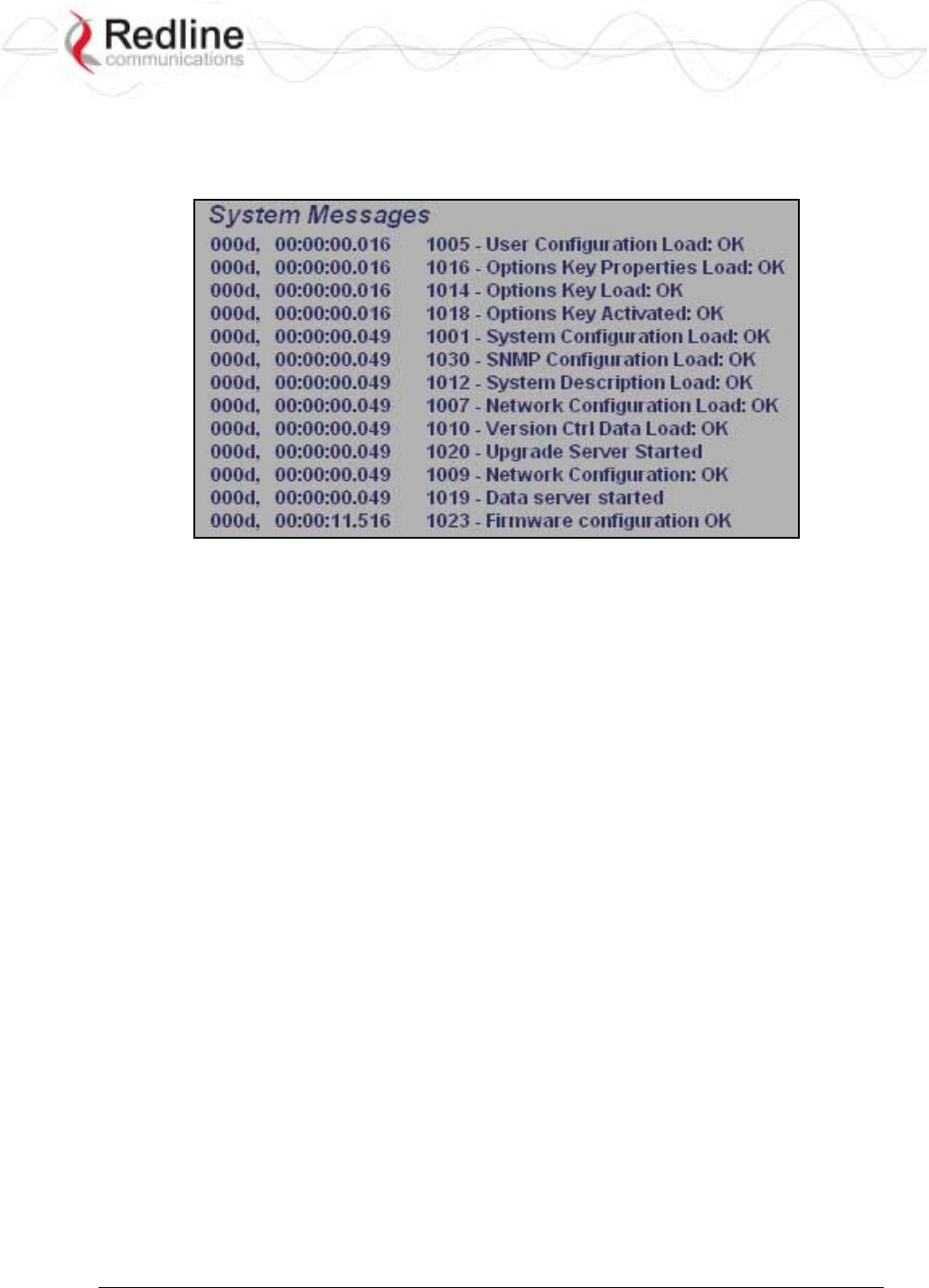
3.5 System Logs Screen
Click System Log in the menu to view the system activity and error messages recorded by
the AN-80i.
Figure 8: Web - System Log Messages
Refer to section 6: Diagnostics and Troubleshooting on page 74 for descriptions of the
system log messages..
RedCONNEXTM AN-80i
PTP & PMP User Manual
70-00072-01-04-DRAFT Proprietary Redline Communications © 2007 May 7, 2007
Page 23 of 90
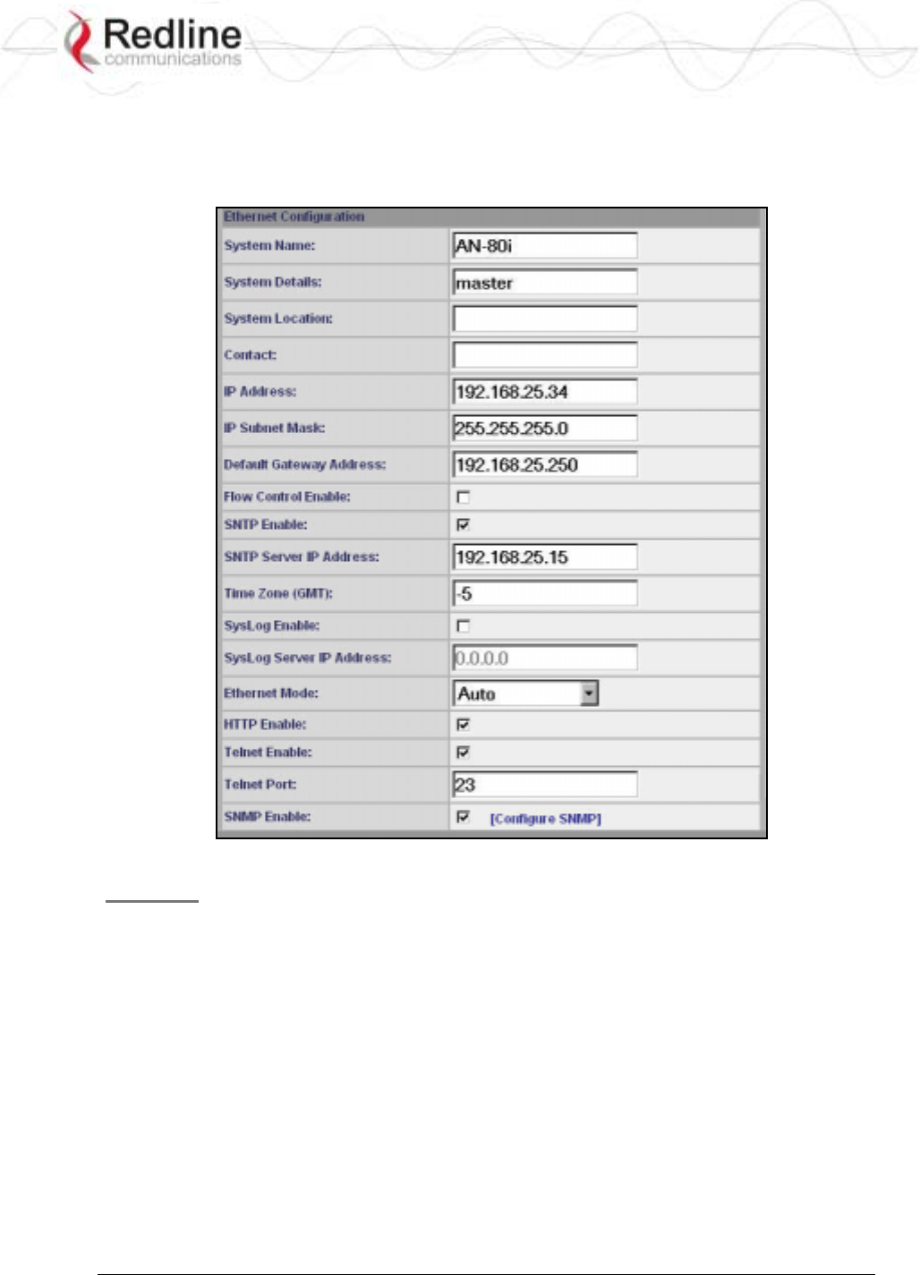
3.6 System Configuration Screen
Click Configure System in the menu to view and adjust configuration settings for general
system identification, Ethernet, and the wireless interface.
Figure 9: Web - System and Network Configuration Screen
General
System Name: Enter the name for this AN-80i. The name can be any combination of
letters and numbers.
System Details: Enter additional descriptive details about this AN-80i. The description
can be any combination of letters and numbers.
System Location: Enter additional descriptive details about this AN-80i. The description
can be any combination of letters and numbers.
Contact: Enter additional descriptive details about this AN-80i. The description can be
any combination of letters and numbers.
IP Address: Enter the IP address for this AN-80i. The IP address is routable through the
Ethernet port and over the wireless interface.
IP Subnet Mask: Enter the IP subnet mask.

RedCONNEXTM AN-80i
PTP & PMP User Manual
70-00072-01-04-DRAFT Proprietary Redline Communications © 2007 May 7, 2007
Page 24 of 90
Default Gateway Address: Enter the IP address of the default gateway or router on the
Ethernet segment connected to the AN-80i Ethernet port.
Flow Control Enable: Check this box to enable flow control functions (802.3x) on
the AN-80i Ethernet port. Enabling this feature allows the AN-80i to request Ethernet
devices to pause transmissions during busy periods.
SNTP Enable: Check this box to enable the SNTP protocol support. This feature
allows AN-80i systems to time-stamp log messages using a network time server. When
enabled, you must enter the network address of the SNTP server in the SNTP Server IP
Address field.
SNTP Server IP Address: Enter the network address of the SNTP server. Valid only
when the SNTP Enable field is checked.
Time Zone (GMT): Enter the hours offset from GMT for this time zone. Valid only
when the SNTP Enable field is checked.
Syslog Enable: Check this box to enable the Syslog protocol support. This feature
allows AN-80i log messages to be saved in a central repository. When enabled, you must
enter the network address of the Syslog server in the Syslog Server IP Address field.
Syslog Server IP Address: Enter the network address of the Syslog server. Valid only
when the Syslog Enable field is checked.
Ethernet Mode: Select the operating mode of the Ethernet port.
Auto - Auto-negotiate the speed connection speed.
10 - Operate at 10Base-T only.
100 - Operate at 100Base-T only.
HD - Operate at half-duplex only.
FD - Operate in full duplex only.
Important: The auto-negotiate feature does not detect the speed and duplex of manually
set Ethernet equipment. The auto-negotiate feature works correctly only when both
communicating Ethernet devices are configured for auto-negotiate. Duplex mismatches
may result in an unexpected loss of communications.
HTTP Enable: Check this box to enable the HTTP (Web) interface. If the option is
deselected, only CLI commands will be available.
Telnet Enable: Check this box to enable a Telnet access (CLI) to the AN-80i. Refer to
the CLI commands in CLI Interface on page 58.
Telnet Port: Enter Telnet port address (default is 23).
SNMP Enable: Check this box to enable the Simple Network Management Protocol
(SNMP) agent. When this item is checked, clicking on the blue text [Configure SNMP]
adjacent to the check box displays the SNMP Configuration screen.
RedCONNEXTM AN-80i
PTP & PMP User Manual
70-00072-01-04-DRAFT Proprietary Redline Communications © 2007 May 7, 2007
Page 25 of 90
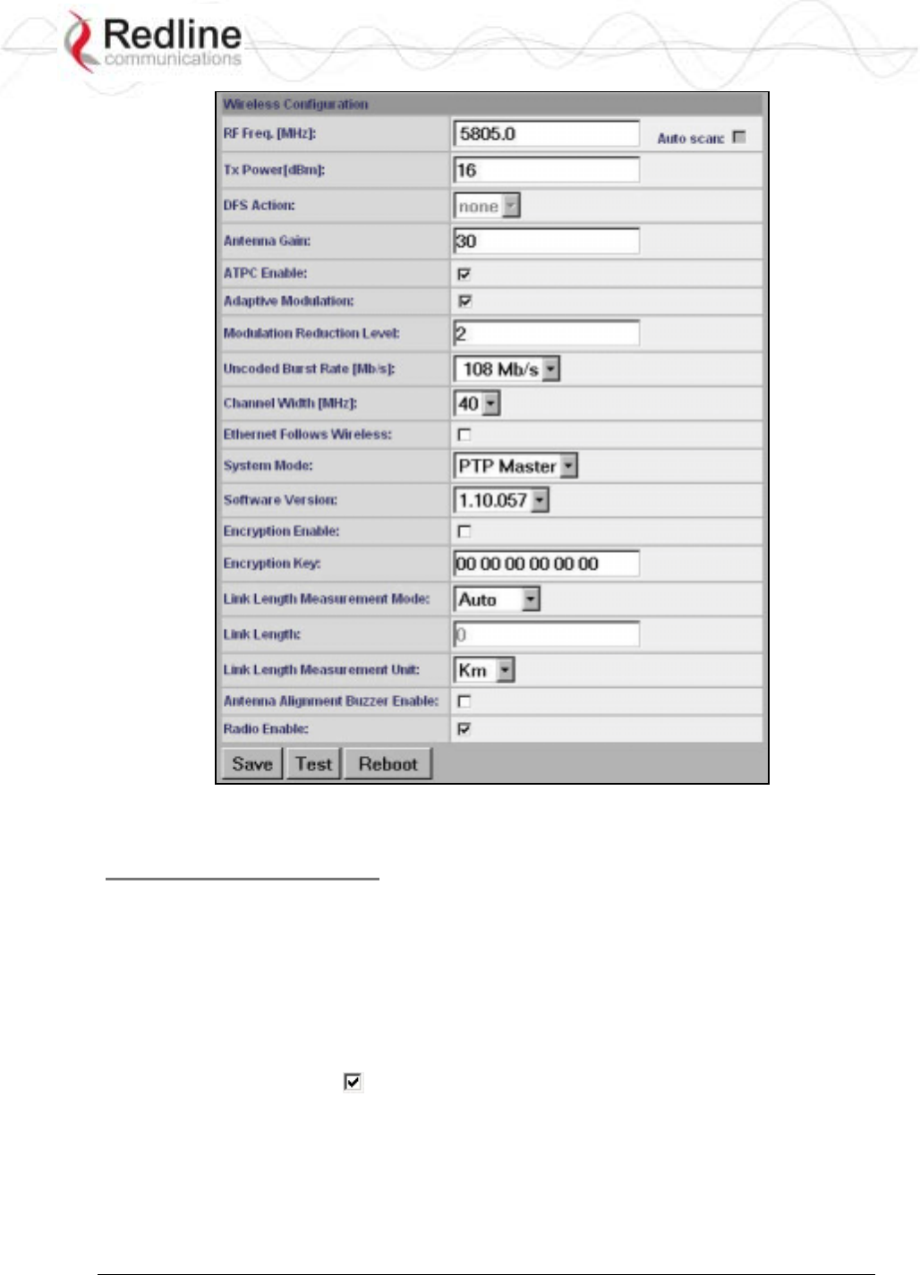
Figure 10: Web - Wireless Configuration Screen
Wireless Configuration
RF Freq. [MHz]: Enter the center frequency for the RF channel. This setting must be
identical for both AN-80i systems operating as a wireless link. The options key controls
channel availability. Refer to Table 43: Spec. - Regional Identification Codes on page 87
for available channels.
Note: To minimize interference, the channel frequencies for AN-80i links operating in
close proximity should be separated by a minimum of the channel size in use (to avoid
overlapping bands).
Auto scan: Check this box to enable the AN-80i PTP Subscriber to automatically scan
available channels and locate the current operating frequency of the AN-80i PTP Sector
Controller.
Tx Power [dBm]: Enter the transmit power level (dBm). This setting is for the
transceiver output only. The actual EIRP depends on the gain of the connected antenna
(see

RedCONNEXTM AN-80i
PTP & PMP User Manual
70-00072-01-04-DRAFT Proprietary Redline Communications © 2007 May 7, 2007
Page 26 of 91
ETSI Certified Antennas on page 84).
Important: In some regions, the maximum operational power per channel for a specific
antenna is limited in accordance with regulations specifying the maximum allowable
EIRP levels. Refer to the FCC and CE notices in this manual.
See Table 2: Web - Max. Power (in dBm) and Modulation to determine the maximum
transmit power level available at each modulation setting. When ATPC is enabled, the Tx
power will be automatically adjusted to achieve optimum performance.
Table 2: Web - Max. Power (in dBm) and Modulation Settings
Modulation BPSK QPSK 16 QAM 64 QAM
Code Rate 1/2 3/4 1/2 3/4 1/2 3/4 2/3 3/4
Max Tx Power 20 20 20 20 20 20 17 17
DFS Action: Select the mode of operation for DFS.
The system set to sector controller-mode monitors for interference from radar devices and
other equipment using the same channel frequency. When interference is detected, the
system automatically takes the action selected using the drop-down menu:
Important: Where DFS is required by regional regulations, this function is permanently
enabled at the factory and can not be disabled by the installer or end-user.
None: The DFS function is disabled.
Tx Off: Transmission is immediately disabled when radar signals are detected. This
action is recorded in the message log and an SNMP trap message is sent (if SNMP
enabled).
Following an interval of thirty minutes, the same channel is monitored for one minute
and if there are no DFS triggering events, the system resumes normal operation. If
DFS trigger conditions are still detected, operation is suspended for an additional
thirty minutes. This cycle continues until no DFS trigger events are detected or the
operator manually reconfigures the system.
Chg Freq: Relocate transmission to an alternative frequency immediately when radar
signals are detected. This action is recorded in the message log and a trap message is
sent (if SNMP enabled).
The new channel is selected based on allowable frequencies for the regulatory region
of that installation. The channel is monitored for one minute before the system is
allowed to transmit. If DFS triggering events are detected, the next available channel
is selected and monitored. The system is not allowed to return to a channel on
which DFS trigger events were detected for a period of thirty minutes. If DFS trigger
events are detected on all channels, operation is suspended until the thirty-minute time
interval expires for at least one channel.
Antenna Gain: Enter the gain (dBm) for the system antenna.
It is important that the Antenna Gain setting matches the actual antenna gain. If the
antenna gain is set higher than the true antenna gain, the system is less sensitive to
detecting interference, and is not operating in compliance with the UK/ETSI standard. If
RedCONNEXTM AN-80i
PTP & PMP User Manual
70-00072-01-04-DRAFT Proprietary Redline Communications © 2007 May 7, 2007
Page 27 of 91
the antenna gain is set lower than the true antenna gain, the system is more sensitive to
interference and this may result in false DFS triggers.
ATPC Enable: Check this box to enable the AN-80i to monitor the received signal
and request that the remote system adjustment its transmit level for optimum
performance. The ATPC feature must be enabled on both AN-80i units.
Adaptive Modulation: Check this box to enable the AN-80i to automatically adjust
the transmission modulation and code settings to achieve the highest UBR that will
operate with a packet error rate (PER at layer 2) of less than 1x10e-6. If the PER exceeds
1x10e-6, the AN-80i automatically adjusts the modulation and code settings downwards
(i.e., from 16 QAM 3/4 to 16 QAM 1/2) to operate at a lower UBR where the PER is
acceptable.
When disabled, the modulation and code settings are entered manually using the
Uncoded Burst Rate setting. See Table 2: Web - Max. Power (in dBm) and Modulation.
Channel Width: Select the channel bandwidth. Refer to Table 43: Spec. - Regional
Identification Codes on page 87 for available channel widths.
Modulation Reduction Level: Enter the number of modulation/coding levels to step
down during re-transmission of errored wireless packets. Each step down lowers the
UBR. The level can be set from 0 to 7 (recommended value = 2).
Uncoded Burst Rate [Mb/s]: Select the desired UBR for the link. If Adaptive
Modulation is disabled, the AN-80i will transmit using only the specified settings. See
Table 2: Web - Max. Power (in dBm) and Modulation.
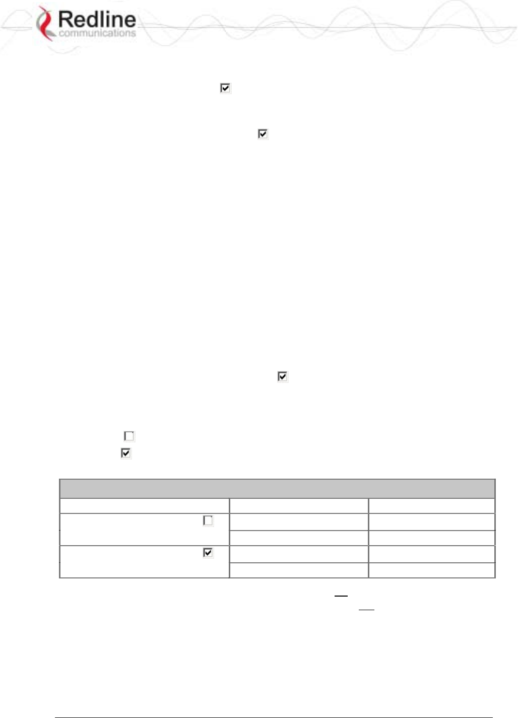
Ethernet Follows Wireless: Check this box to have the AN-80i disable and enable the
Ethernet port function based on the status of the wireless interface. This feature allows
switches and routers to trigger configuration changes based on changes to the AN-80i
Ethernet port status.
Disabled ( ): The AN-80i Ethernet port is always enabled.
Enabled ( ): The Ethernet port status is controlled based on the status of the wireless
interface. See the following table.
Table 3: Web - Ethernet Status Indication
Configuration Setting Wireless interface Status Ethernet Port Status
Ethernet Follows Wireless Link Up Enabled
Link Down Enabled
Ethernet Follows Wireless Link Up Enabled
Link Down Disabled
Important: The Ethernet Follows Wireless setting affects all data and management traffic
(HTTP, TELNET, and SNMP). When enabled, it is not possible to establish
communications with the AN-80i using the Ethernet port while the wireless interface is
down. If the wireless interface is down, the Ethernet Follows Wireless setting can only be
set to 'off' by using the IP recovery procedure. See 6.2: Procedure to Reset AN-80i IP
Address on page 75.
System Mode: Set the operating mode for each AN-80i system.

RedCONNEXTM AN-80i
PTP & PMP User Manual
70-00072-01-04-DRAFT Proprietary Redline Communications © 2007 May 7, 2007
Page 28 of 91
PTP Sector Controller: This unit begins transmitting automatically; sends poll
messages to the remote AN-80i, and negotiates the wireless link.
PTP Subscriber: This unit waits passively, monitoring the selected channel(s) until
polled by the PTP Sector Controller, and participates in negotiating the wireless link.
Software Version: Select the version of system software to load when the AN-80i is
rebooted. The system holds two independent software images.
Encryption Enable: Check this box to enable encryption of data transmitted over the
wireless interface. When encryption is enabled, no Ethernet packets can be transferred
over-the-air unless encryption is enabled on the remote-end AN-80i, and the correct
encryption key is entered on both AN-80i units.
Encryption Key: The key is used to encrypt data in a way that can be decoded by the
remote-end AN-80i. Enter the MAC address of the communicating AN-80i.
Link Length Measurement Mode: Select the mode for setting/measuring the distance
between this and the remote-end AN-80i.
Auto: Distance is calculated automatically by the AN-80i.
Manual: Enter the link distance manually in the Link Length field.
Link Length: Enter the actual length of the path that the radio wave travels between the
two AN-80i units. The Link length is used to calculate the transmission-to-response
interval and reject reflections of the transmitted signal. This setting is valid only when the
Link Length Mode is set to Manual.
Link Length Measurements Unit: Select the units for the Link Length field.
Mile: Link length distance is displayed in miles.
Km: Link length distance is displayed in kilometers.
Antenna Alignment Buzzer Enable: Check this box to enable the antenna alignment
audible tone generator in the transceiver. The rate of the tone is proportional to the
receive signal strength (faster = stronger signal).
Radio Enable: Check this box to enable the radio transmitter. If this box is unchecked
(), it will not be possible to establish a wireless link.
Controls
Save: Click to save the parameter settings displayed in the configuration screen.
Note: Changes to some parameters cause the AN-80i to initiate a system reset when the
Save button is selected.
Test: Click this button to have the AN-80i load the current settings displayed in the
configuration screen. The AN-80i will operate with these settings for a period of five
minutes. During the 'test' period, you may click the Save button at any time to save this
configuration permanently (also terminating the five minute timer). If the Save button is
not selected during the five minute test period, the AN-80i is rebooted and the previously
saved settings are reloaded.
System Reboot: Click this button to immediately reboot the AN-80i. All statistics
counters are reset.
RedCONNEXTM AN-80i
PTP & PMP User Manual
70-00072-01-04-DRAFT Proprietary Redline Communications © 2007 May 7, 2007
Page 29 of 91
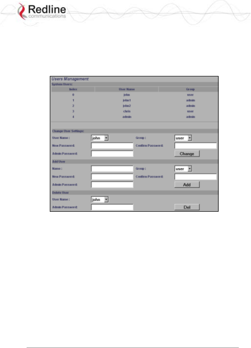
3.7 System Password Screen
Click Users Management in the left hand menu to display the System Password screen.
This screen allows the operator to modify the system passwords.
The AN-80i supports two groups of users: admin and user. See Table 5: Web - Default
System Users on 30 for the factory default login values. See Table 4: Web - Screens and
User Access on page 30 for permissions associated with each group.
Figure 11: Web - System Password Screen
Change User Settings
Use this dialog to change the settings for an existing user.
User name: Select an existing user to be modified.
Group: Select the group to be associated with this username.
New Password: Enter the new password for this user.
Confirm Password: Re-enter new password for this user.
Admin Password: Enter the administrator password (security feature).
Change: Click the Change button to make these changes effective.
Add User
Use this dialog to add a new user.
User name: Enter a name for the new user.
Group: Select a group for the new user.
New Password: Enter a password for the new user.
Confirm Password: Re-enter the password for the new user.
RedCONNEXTM AN-80i
PTP & PMP User Manual
70-00072-01-04-DRAFT Proprietary Redline Communications © 2007 May 7, 2007
Page 30 of 91
Admin Password: Enter the administrator password (security feature).
Add: Click the Add button to make these changes effective.
Delete User
Use this dialog to delete an existing user.
User name: Select an existing user.
Admin Password: Enter the administrator password (security feature).
Del: Click the Del button to make these changes effective.
Group Permissions
The following table lists the permissions associated with each group.
Table 4: Web - Screens and User Access
Screen Admin
Access User
Access Description
General Information X X View general system identification and
configuration settings.
System Status X X View system information, Ethernet statistics, and
wireless statistics.
System Log X X View the system status messages recorded by
the AN-80i.
Configure System X View and adjust configuration system, IP
address, management, and wireless settings.
Upload Software X Upload a new software binary file.
Users Management X
X
X Change your login password.
Add and delete users.
Product Options X View and change the product options key.
Spectrum Sweep X Scan a range of frequencies to detect other RF
sources (interference).
Links X
Groups X
New Link X
New Group X
New Connection X
Save X
Clear All X
The following table lists the default login names and passwords.
Table 5: Web - Default System Users
Group User Name Default Password
user user user
admin admin admin
Important: There must always be at least one 'administrator' account active
on the AN-80i. You can not manage the AN-80i if all accounts are 'user'.
RedCONNEXTM AN-80i
PTP & PMP User Manual
70-00072-01-04-DRAFT Proprietary Redline Communications © 2007 May 7, 2007
Page 31 of 91
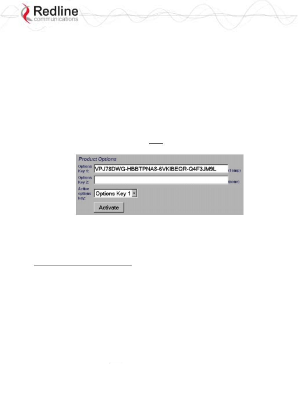
3.8 AN-80i Product Options Screen
Click Product Options in the left hand menu to display the Product Options screen.
You may not be able to establish a link between AN-80i units, or configure all required
parameter settings until you have entered the permanent options key. Permanent options
keys must be purchased and are provided in electronic format. The options key (a string
of numbers, letters, and dashes) enables AN-80i features including the maximum
uncoded burst rate and frequency ranges (region codes). Every options key is unique to
an AN-80i unit.
Each new AN-80i received from the factory will contain a temporary options key. This
temporary key may provide temporary access to advanced options and settings. When the
factory options key expires, only limited service will be available (restricted RF
frequency, data rates, etc).
Important: A permanent Options Key must be entered for in-service operation. The
factory temporary options key will expire and service will be interrupted.
Figure 12: Web - Product Options Screen
Options Key 1: Enter a valid permanent or temporary options key.
Options Key 2: Enter a valid permanent or temporary options key.
Active Options Key: Select the options key to use.
Entering the Options Key
1. Enter the key (case sensitive).
2. Review the entry to verify that the entered value is correct.
3. Select the options key to activate.
4. Click the Activate button to use the options associated with this key.
5. Click System Log in the menu and verify the key has been accepted.
Notes:
1. At least one valid permanent options key is required for operation. The system will prevent
the operator from deleting all valid keys.
2. Keys are shared between PMP and PTP operation.
3. The active key selection must be made by the user. The software will use any valid selected
permanent or temporary key.
4. The software will switch to the second options key if the first key is not valid (e.g., expired
temporary key or when switching between PTP to PMP mode).
RedCONNEXTM AN-80i
PTP & PMP User Manual
70-00072-01-04-DRAFT Proprietary Redline Communications © 2007 May 7, 2007
Page 32 of 91
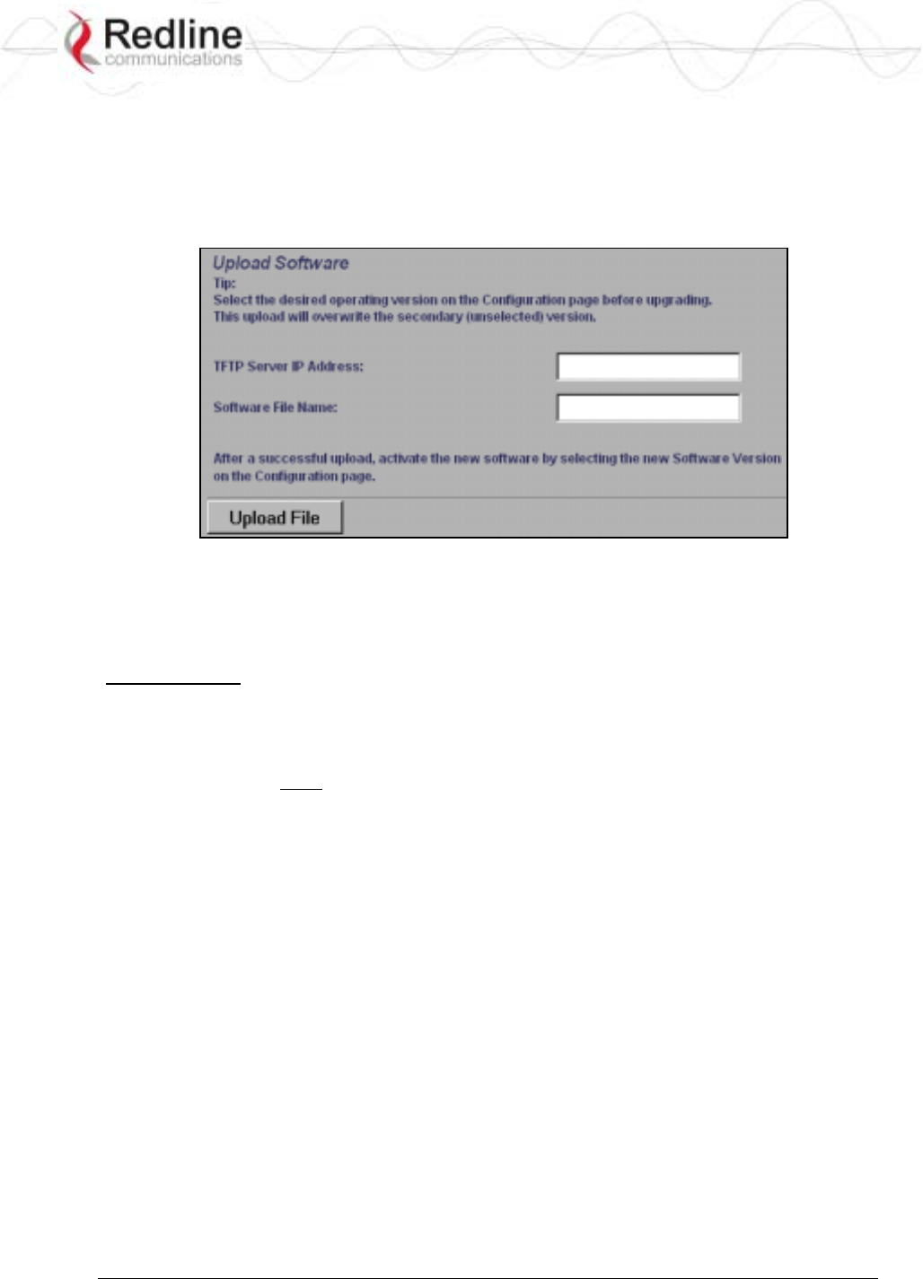
3.9 Upload Software
Click Upload Software in the left hand menu to display the Upload Software screen. This
screen is used to upgrade the AN-80i with new software. The AN-80i contains non-
volatile storage for two versions of the software. The upload overwrites the non-
operational (unselected) version.
Figure 13: Web - Upload Software Screen
TFTP Server IP Address: Enter the IP address of the computer with the software
upgrade file. This computer must be running a TFTP server.
Software File Name: Name of the software binary file (including file extension).
Upgrade Steps
Trivial File Transfer Protocol (TFTP) is used to upload the new software image file from
your computer to the AN-80i. A TFTP server software must be installed and running on
the computer you are using to upload the new software file. In addition, the AN-80i
software binary file must be located in the default upload directory for the TFTP server.
1. Enter the IP Address of the computer running the TFTP server.
2. Enter the full name of the binary file (including the .bin extension).
3. Click the Upload File button to begin the file transfer. The upgrade file size is
approximately two Megabytes and takes a minimum of two to four minutes to
transfer. Slower network connections may take longer -- do not interrupt the transfer
process.
4. When the file transfer is complete, the AN-80i verifies the integrity of the new
software file. If errors were introduced during the transfer process, the software file is
rejected and a warning message is registered in the event log, and you must repeat the
upload.
5. When the transfer has completed successfully, use the System Configuration screen to
select which software version to load on the next system reboot (does not switch
automatically following upload).
RedCONNEXTM AN-80i
PTP & PMP User Manual
70-00072-01-04-DRAFT Proprietary Redline Communications © 2007 May 7, 2007
Page 33 of 91
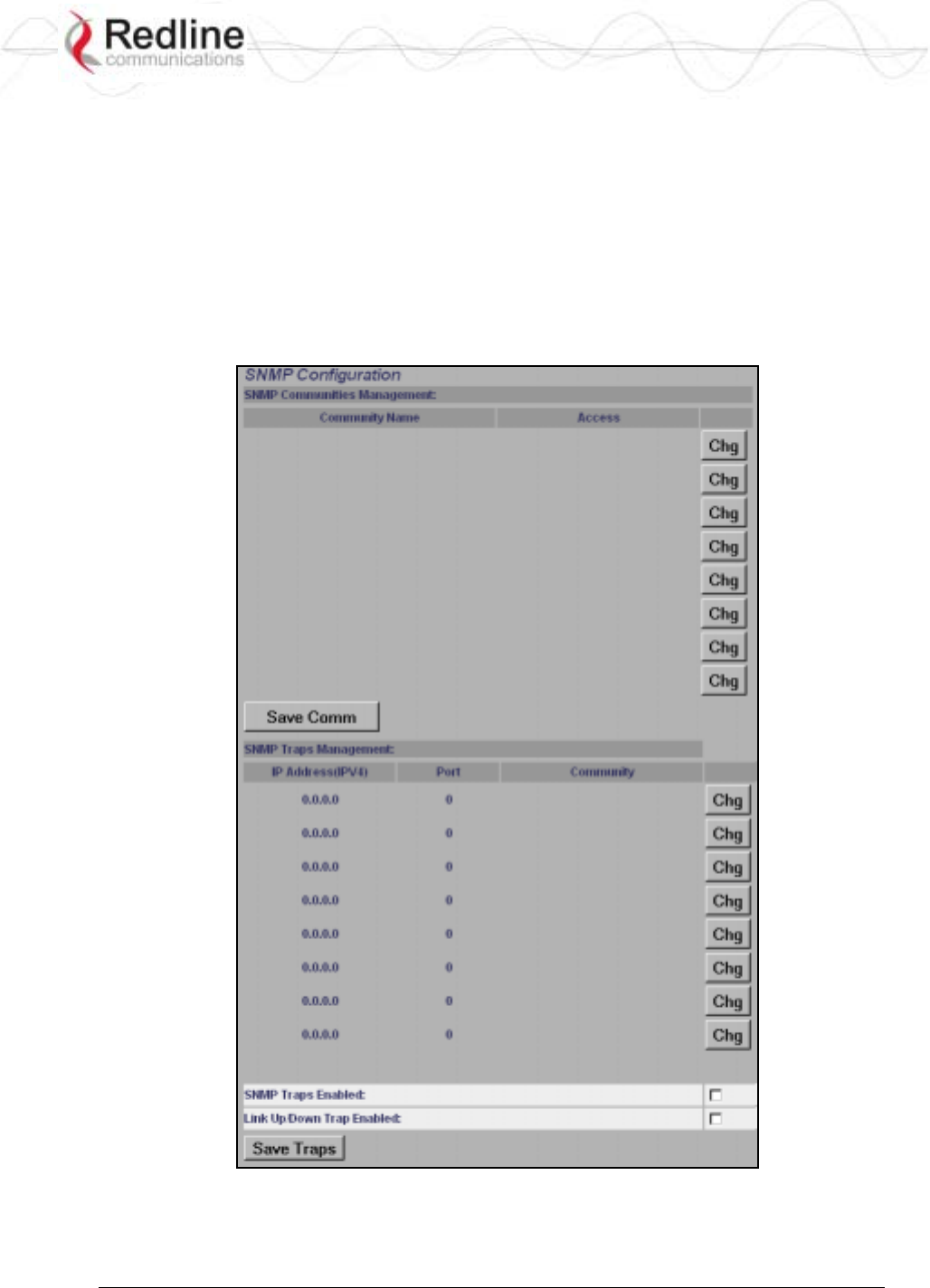
3.10 SNMP Settings Screen
Click Configure SNMP (blue text) on the System Configuration screen to view and edit the
SNMP settings. The hyperlink appears only if the SNMP Enable box is checked.
The SNMP protocol allows an application to interrogate the AN-80i for information
saved in the MIB an to change enabled fields within the MIB. When the SNMP Agent in
the AN-80i detects an error condition, a special message known as a trap can be sent (if
enabled). A Trap Host is an IP system/server that is set up to receive SNMP trap
messages. The SNMP Configuration screen displays a list of the current communities.
The Chg buttons can be used to add, edit, or delete community settings.
Figure 14: Web - SNMP Configuration Screen
SNMP Community Management
Community Name: Displays the SNMP community name for each entry (maximum of
eight entries).
RedCONNEXTM AN-80i
PTP & PMP User Manual
70-00072-01-04-DRAFT Proprietary Redline Communications © 2007 May 7, 2007
Page 34 of 91
Access: Displays the access permissions for each SNMP community.
None: Deny read and write permission for this community.
Read: Grant read access permission only for this community. Deny write permission.
Write: Grant write access permission only for this community. Deny read permission.
Read&Write: Grant read and write access permission for this community.
Chg: Click the Chg button to modify the settings for the adjacent entry.
Save Comm: Click the Save Comm button to save changes to the community settings.
SNMP Traps Management
IP Address(IPv4): IP address associated with this SNMP alarm.
Port: Destination port address associated with this SNMP alarm.
Community: Community associated with this SNMP alarm.
Chg: Click the Chg button to modify the settings for the adjacent entry.
SNMP Traps Enabled: Check this box to enable SNMP traps to be sent. If the box is
not checked, all SNMP traps are disabled.
Link Up/Down Trap Enabled: Check this box to enable an SNMP trap to be generated
for each link up and link down event.
Save Traps: Click the Save Traps button to save changes to the SNMP trap settings.
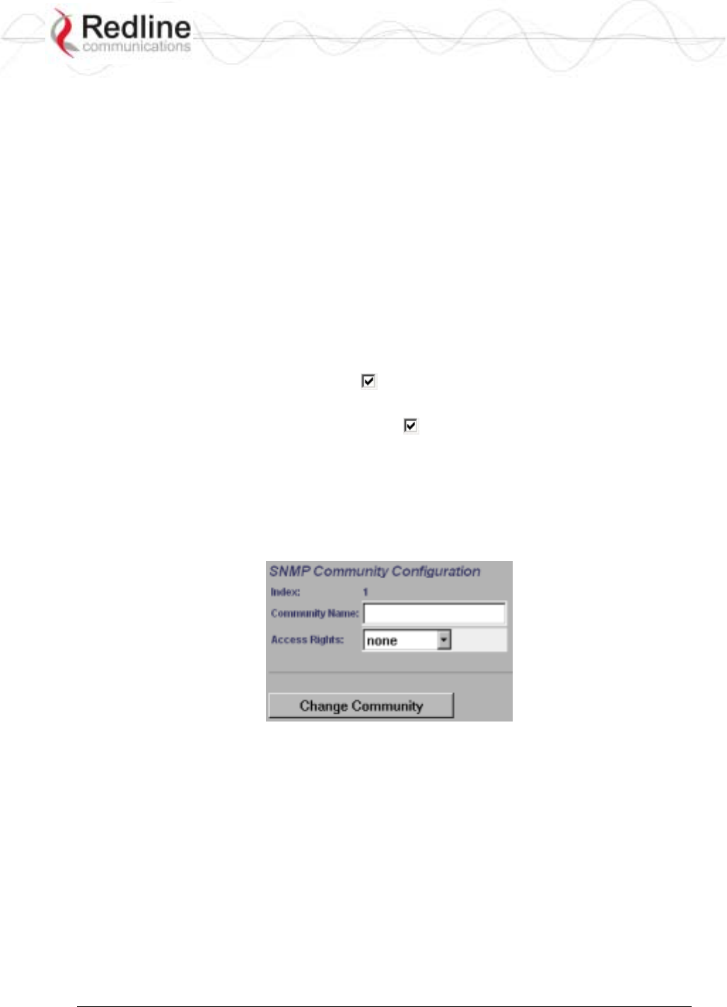
3.10.1 Change SNMP Community
Each entry in the SNMP Community Management table may be changed individually.
Click the Chg button adjacent to any entry to modify the settings.
Figure 15: Web - SNMP Community Configuration Screen
Index: Display the unique reference number for this entry.
Community Name: Enter or modify the SNMP community name for this entry.
Access Rights: Select the access permissions for this entry.
None: Deny read and write permission for this entry.
Read: Grant read access permission only for this entry. Deny write permission.
Write: Grant write access permission only for this entry. Deny read permission.
Read&Write: Grant read and write access permission for this entry.
Change Community: Click the Change Community button to copy these settings to the
community settings table. This action does not permanently save changes. To save
changes to the community settings you must also click the Save Comm button in the
SNMP Configuration screen.
RedCONNEXTM AN-80i
PTP & PMP User Manual
70-00072-01-04-DRAFT Proprietary Redline Communications © 2007 May 7, 2007
Page 35 of 91
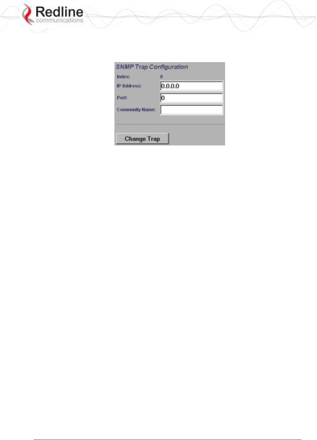
3.10.2 Change SNMP Trap Configuration
Each of the eight entries in the SNMP Traps Management table may be changed
individually. Click the Chg button to modify the settings for the adjacent entry.
Figure 16: Web - SNMP Trap Configuration Screen
Index: Display the table position number for this entry. Position 0 is the first entry.
IP Address: Enter the IP address (IPv4) associated with this SNMP alarm.
Port: Enter the destination port address associated with this SNMP alarm.
Community Name: Enter the SNMP community name for this entry.
Change Trap: Click the Change Trap button to copy these settings to the community
settings table. This action does not permanently save changes. To save changes to the
SNMP trap settings you must click the Save Traps button in the SNMP Configuration
screen.
RedCONNEXTM AN-80i
PTP & PMP User Manual
70-00072-01-04-DRAFT Proprietary Redline Communications © 2007 May 7, 2007
Page 36 of 91
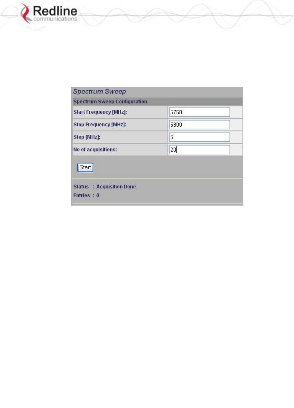
3.11 Spectrum Sweep
Click Spectrum Sweep in the left hand menu to display the Spectrum Sweep configuration
screen. The spectrum sweep feature is an off-line RF survey tool to detect interference
and evaluate spectrum availability. Configurable survey parameters include the high and
low frequency limits, the step size, and the number of samples at each step. The output
graph displays the maximum (red) and average (blue) RSSI for each step.
Figure 17: Web - Spectrum Sweep Screen
Start Frequency (MHz): Enter center frequency of the lowest channel to be scanned.
See Table 43: Spec. - Regional Identification Codes on page 87.
End Frequency (MHz): Enter center frequency of the highest channel to be scanned. See
Table 43: Spec. - Regional Identification Codes on page 87.
Step (MHz): Enter the frequency step (MHz) to use when scanning from the lowest to
the highest frequency. The step selection must be a multiple of 2.5 MHz (i.e., 2.5, 5, etc).
No. of acquisitions: Enter the number of times the frequency will be sampled at each
step. The recommended range is 10 to 100 samples. When a potentially clear channel is
identified, reduce the frequency range and step size while increasing the sample size to
monitor the channel over a longer period.
Start: Left-click the Start button to begin the scan.
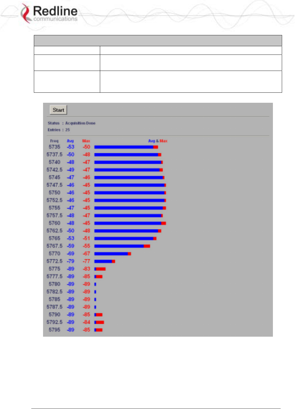
Performing a Sweep
The transmitter of the Sector Controller is automatically disabled during the spectrum
scan. If the scan is being performed from a Subscriber, the transmitter on the remote AN-
80i for this link should be disabled during the test. You can use the configuration test
feature to remotely (over-the-air) shut down the remote transmitter for 5 minutes and then
recover automatically. See the description of the Test button in System Configuration
Screen under the heading Controls on page 28.
RedCONNEXTM AN-80i
PTP & PMP User Manual
70-00072-01-04-DRAFT Proprietary Redline Communications © 2007 May 7, 2007
Page 37 of 91
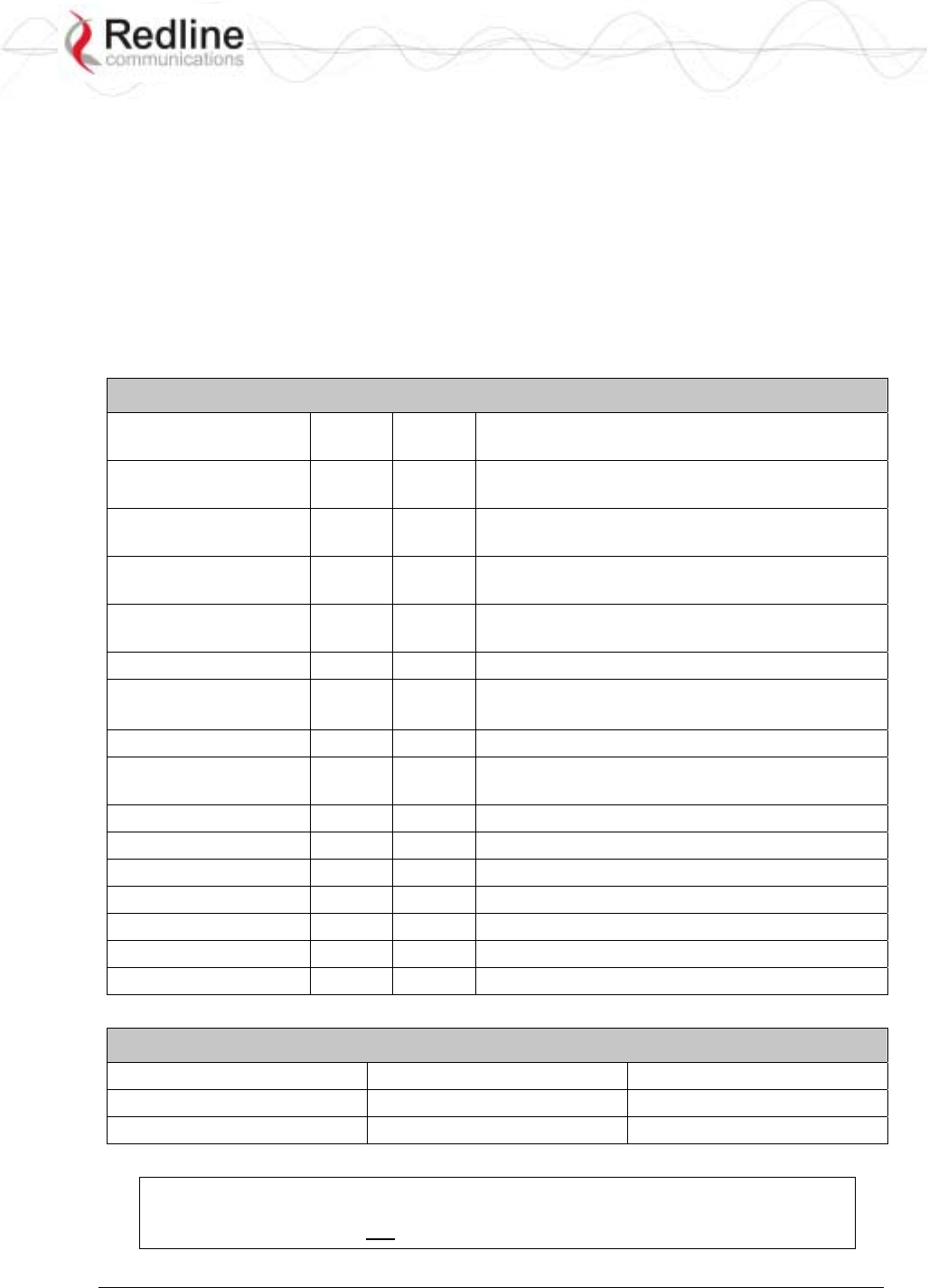
Table 6: Web - Performing a Spectrum Sweep
Setting Description
System Mode:
Subscriber
No action required: Remote end will remain passive during sweep.
System Mode:
Sector Controller
Use Web/CLI to disable radio on remote-end. Use 'test' function to
save and remote end will restore radio operation automatically after
5 minutes.
Figure 18: Web - Spectrum Sweep Results