Remote Diagnostic Technologies TEMPUSIC-1 Tempus IC Patient Monitor User Manual
Remote Diagnostic Technologies Ltd. Tempus IC Patient Monitor
UserManual.wiki
>
Remote Diagnostic Technologies
>
TEMPUSIC 1 User Manual
User manual
Navigation menu
Upload a User Manual
Namespaces
Wiki Guide
HTML
PDF
Info
Views
User Manual
Discussion / Help
Navigation
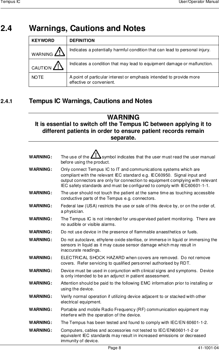
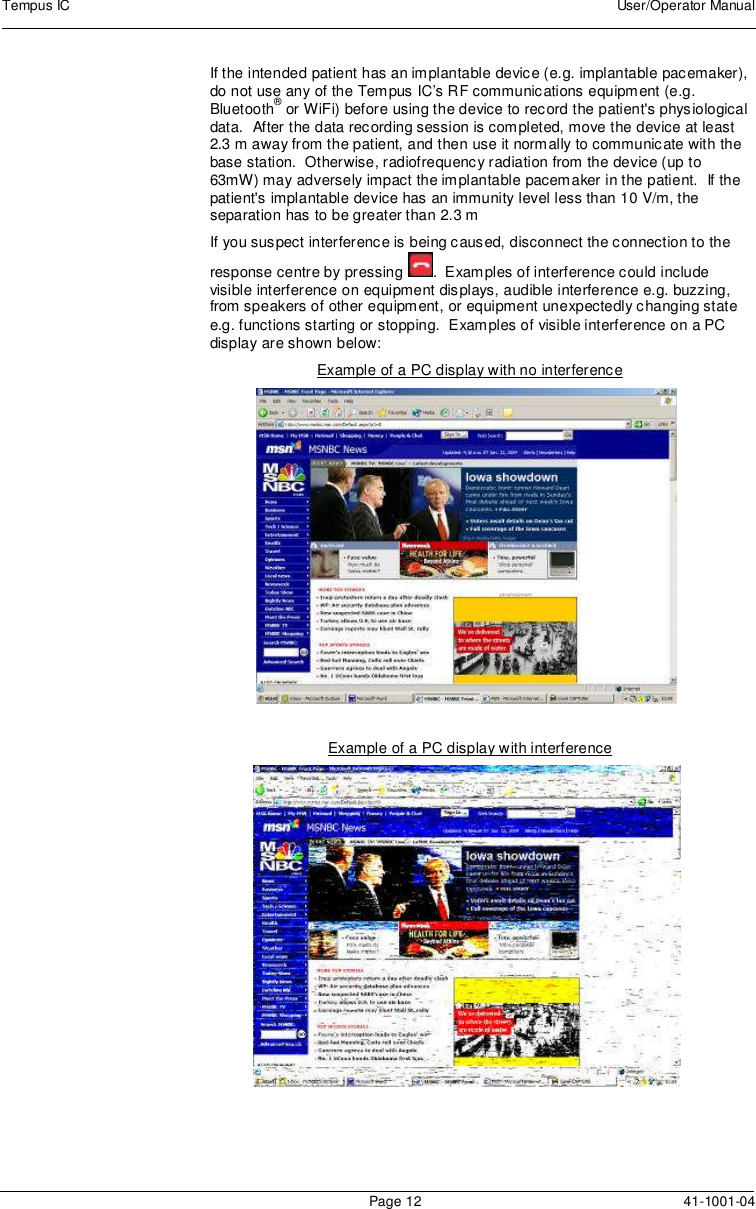
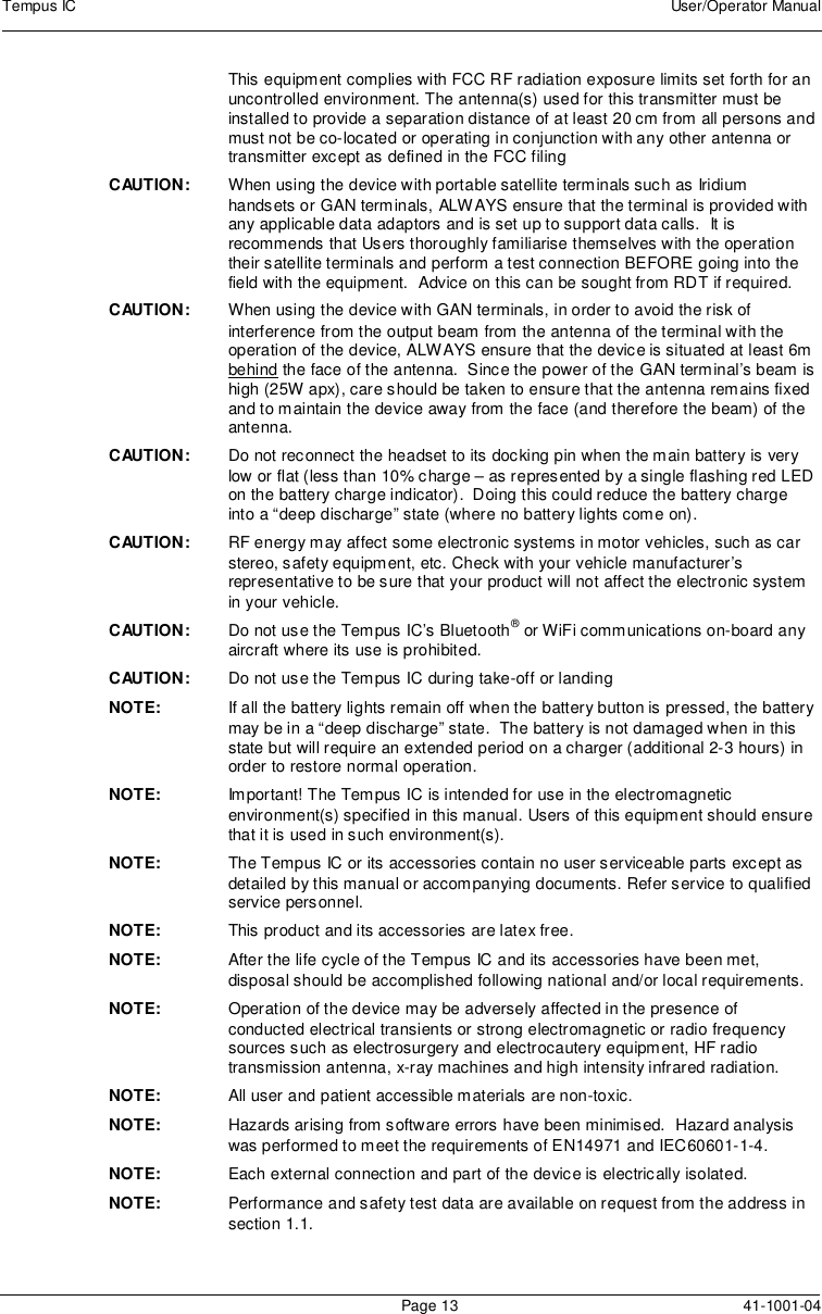
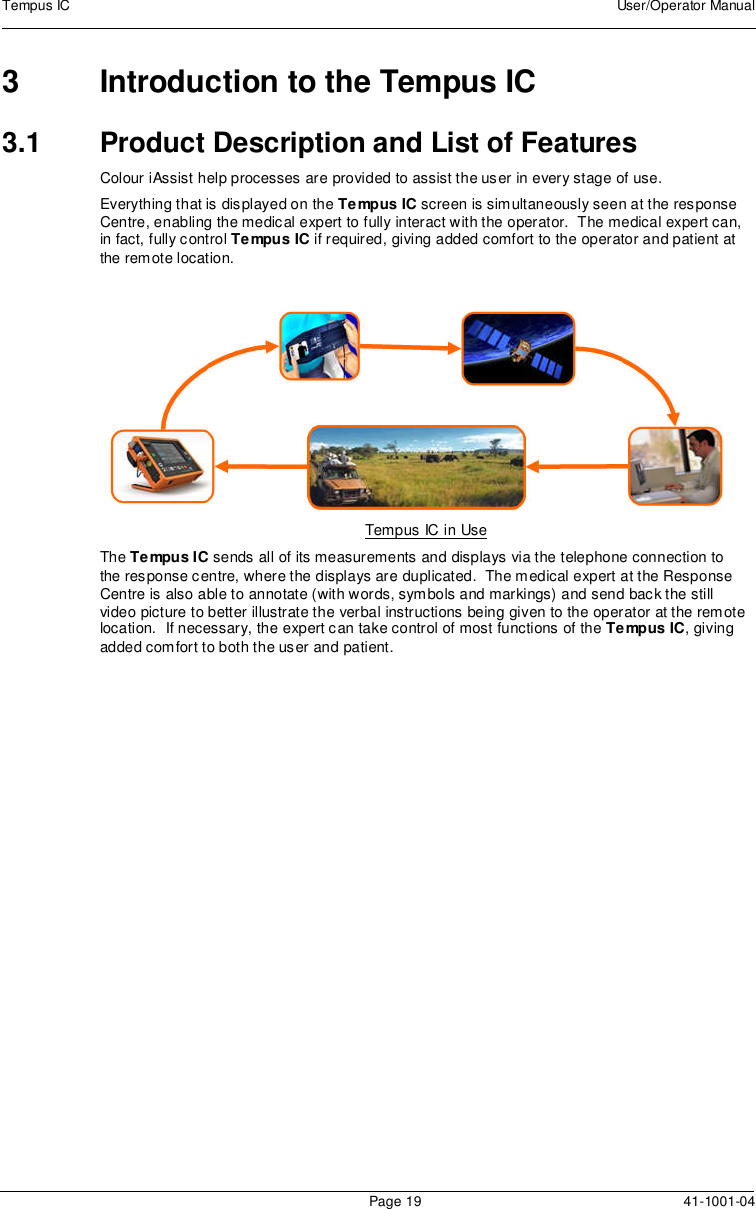
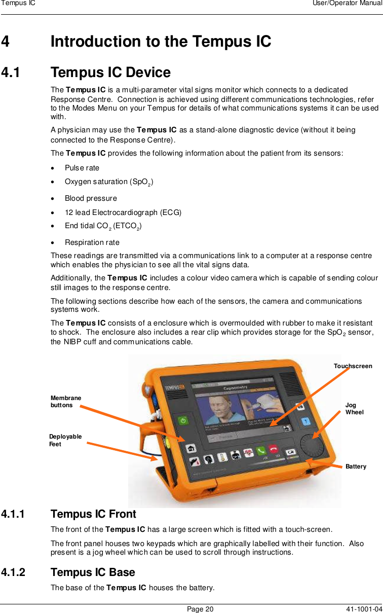
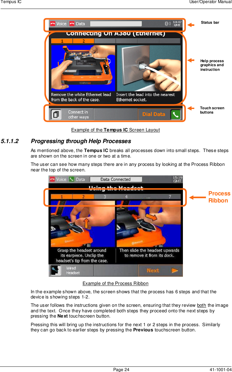
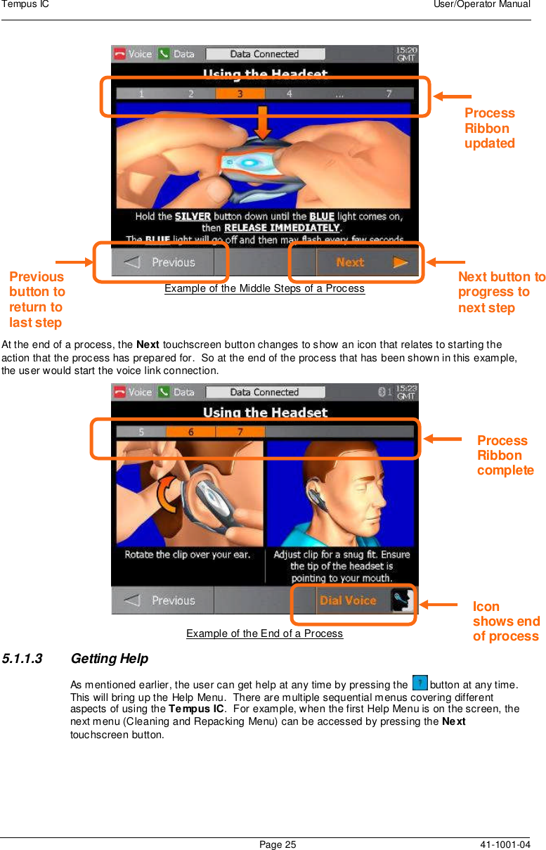
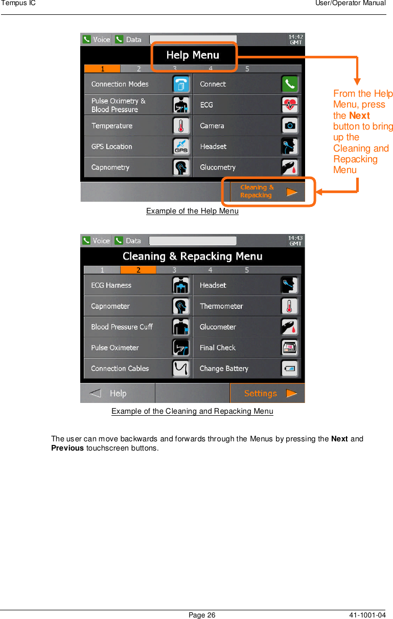
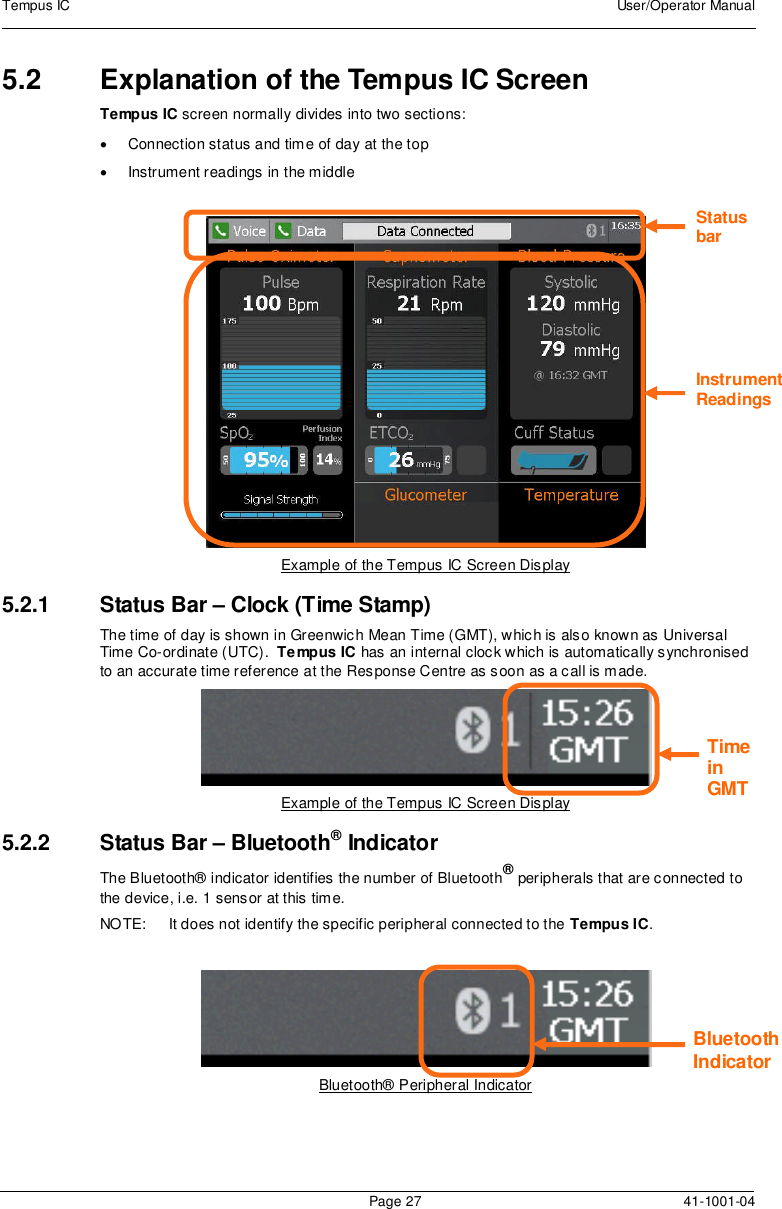
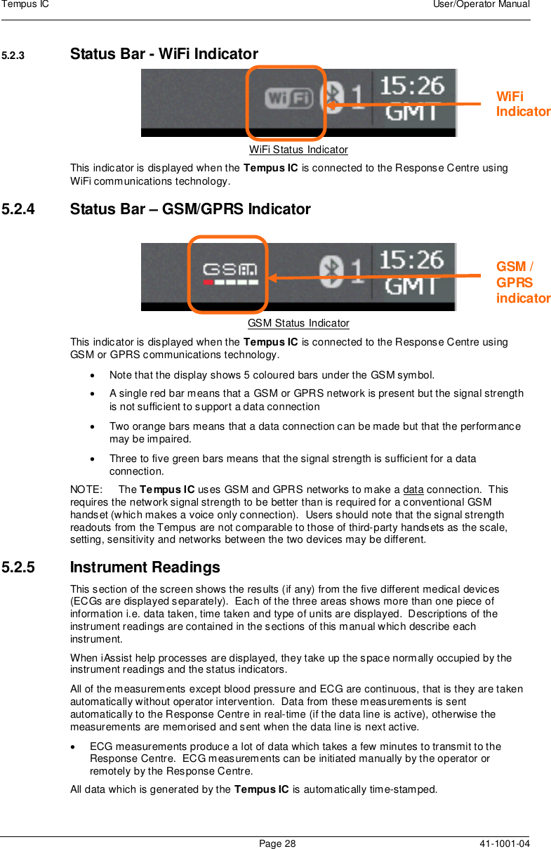
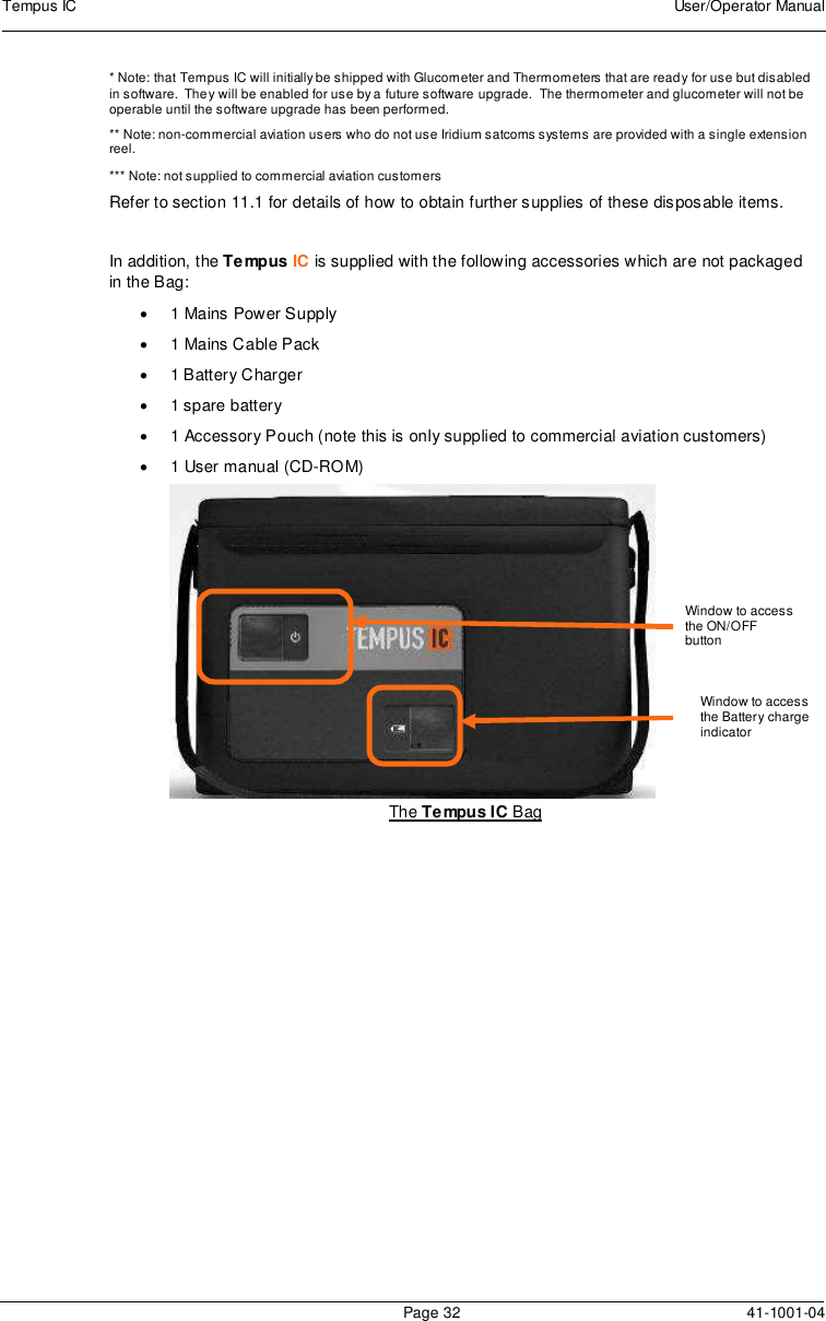
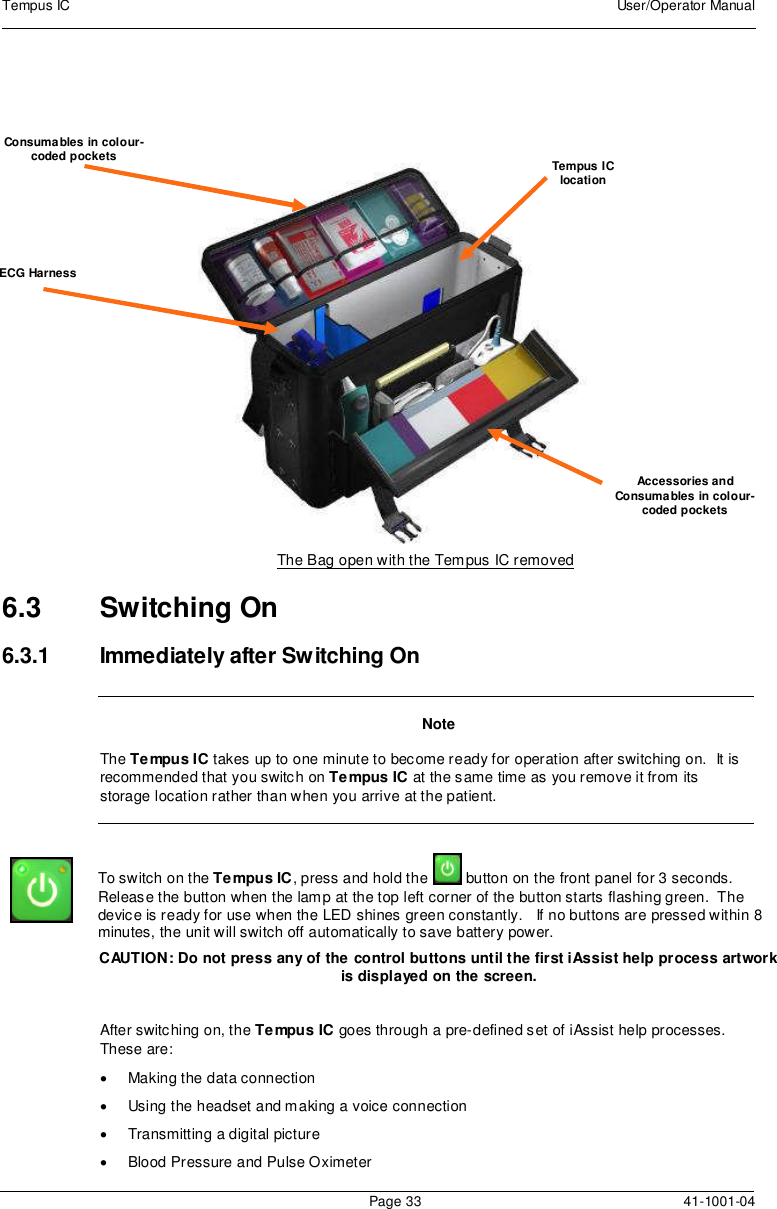
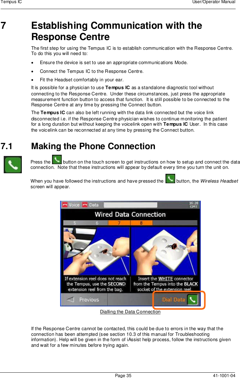
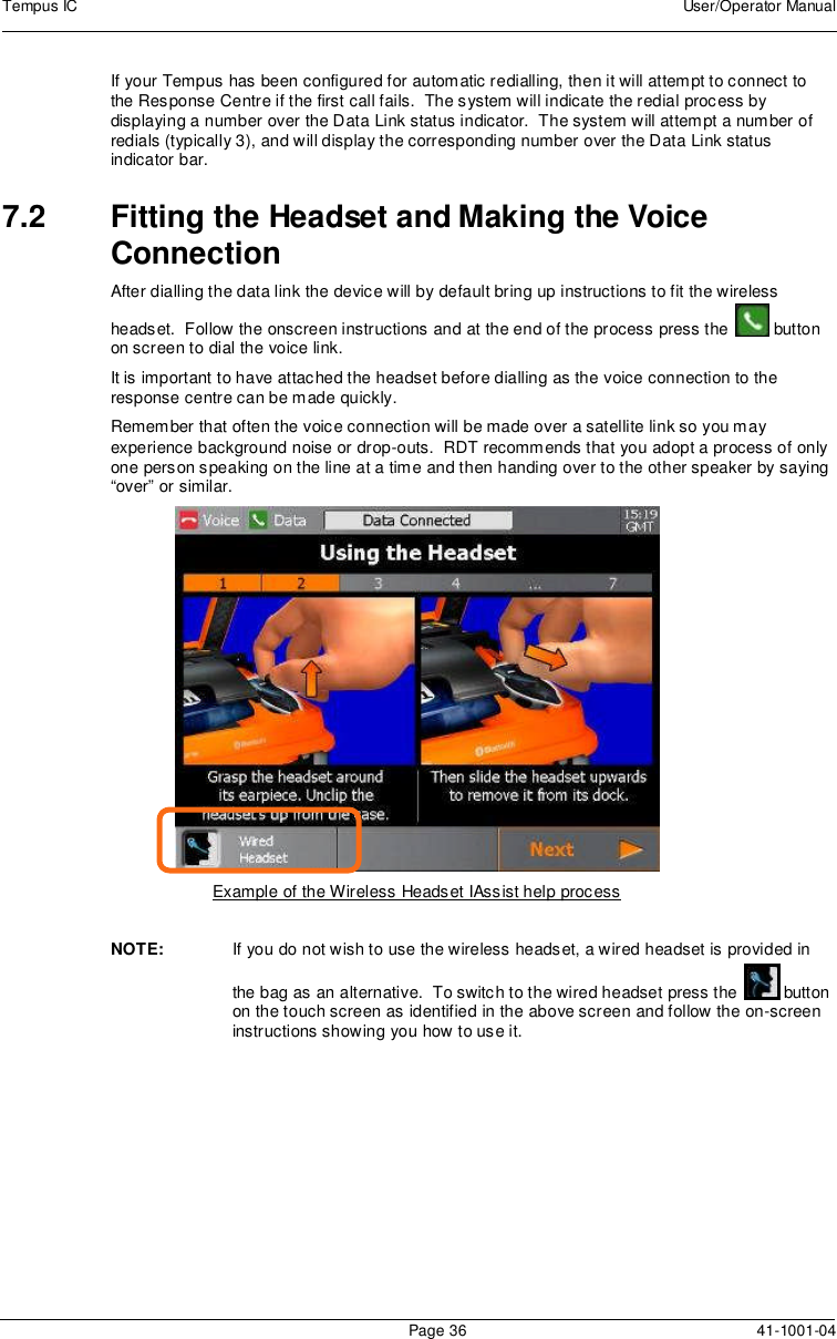
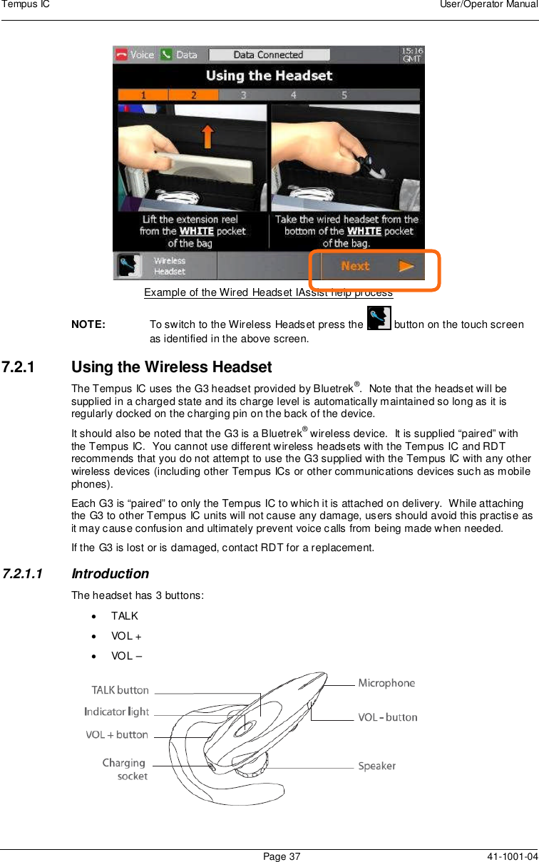
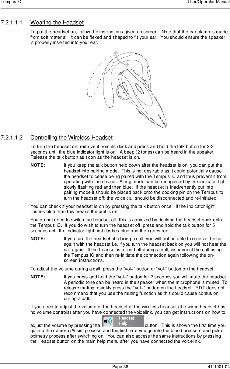
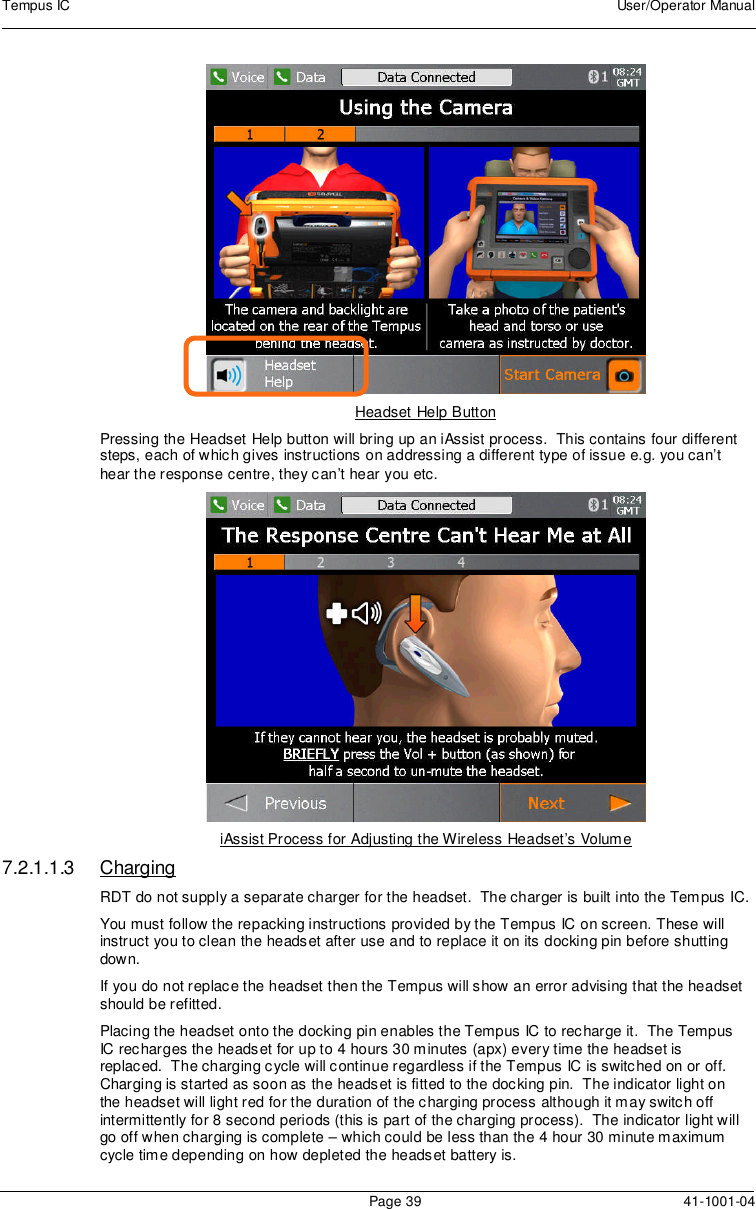
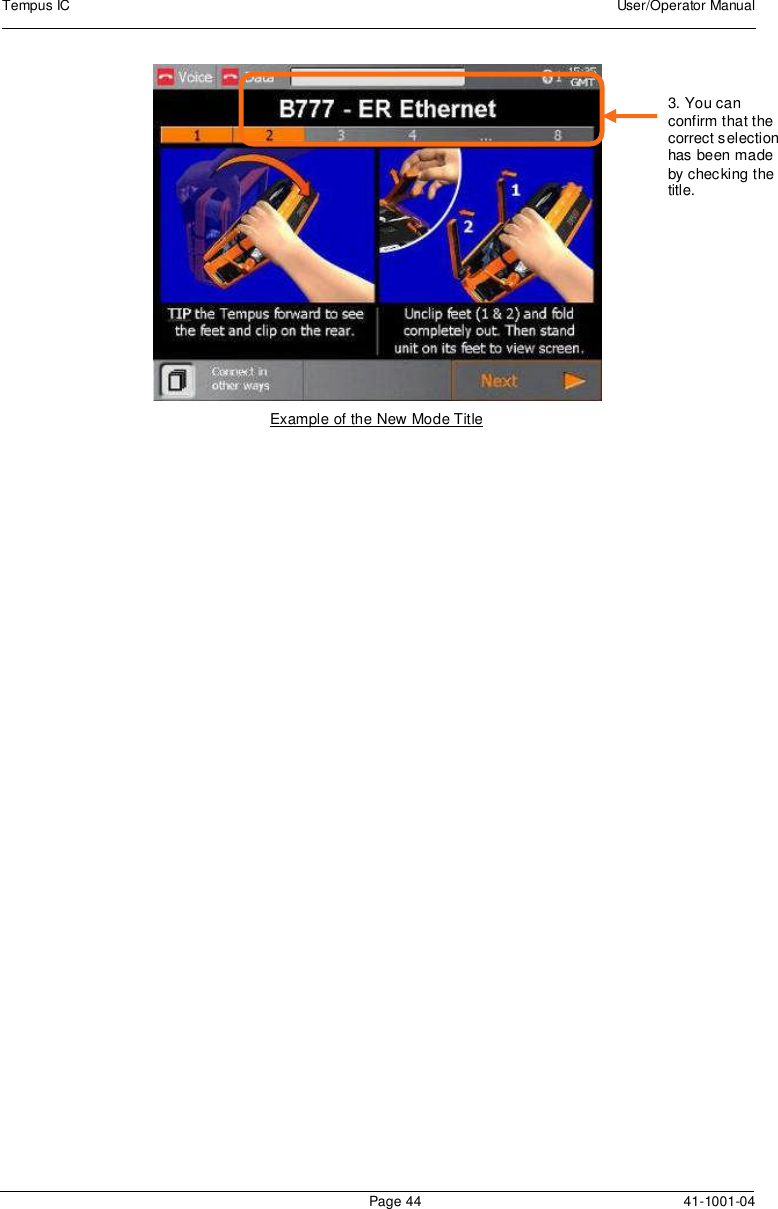
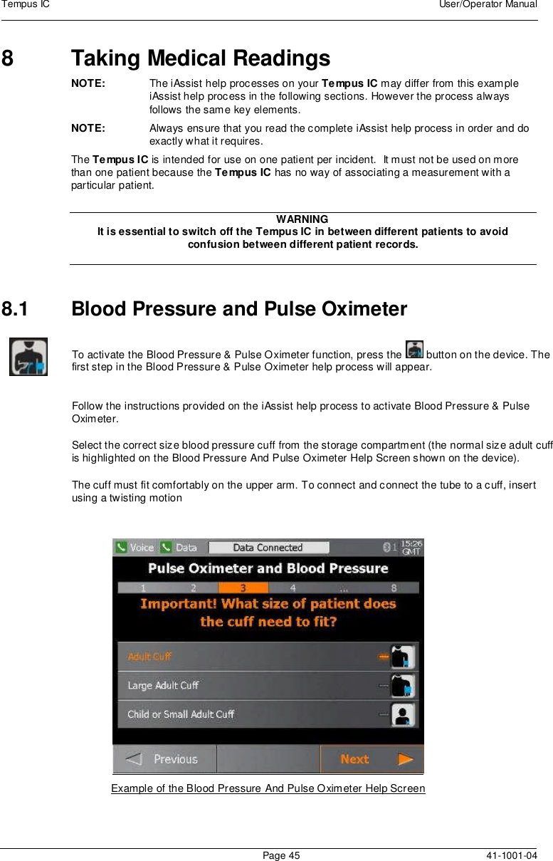
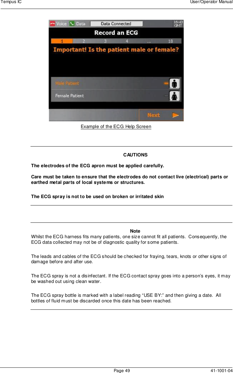
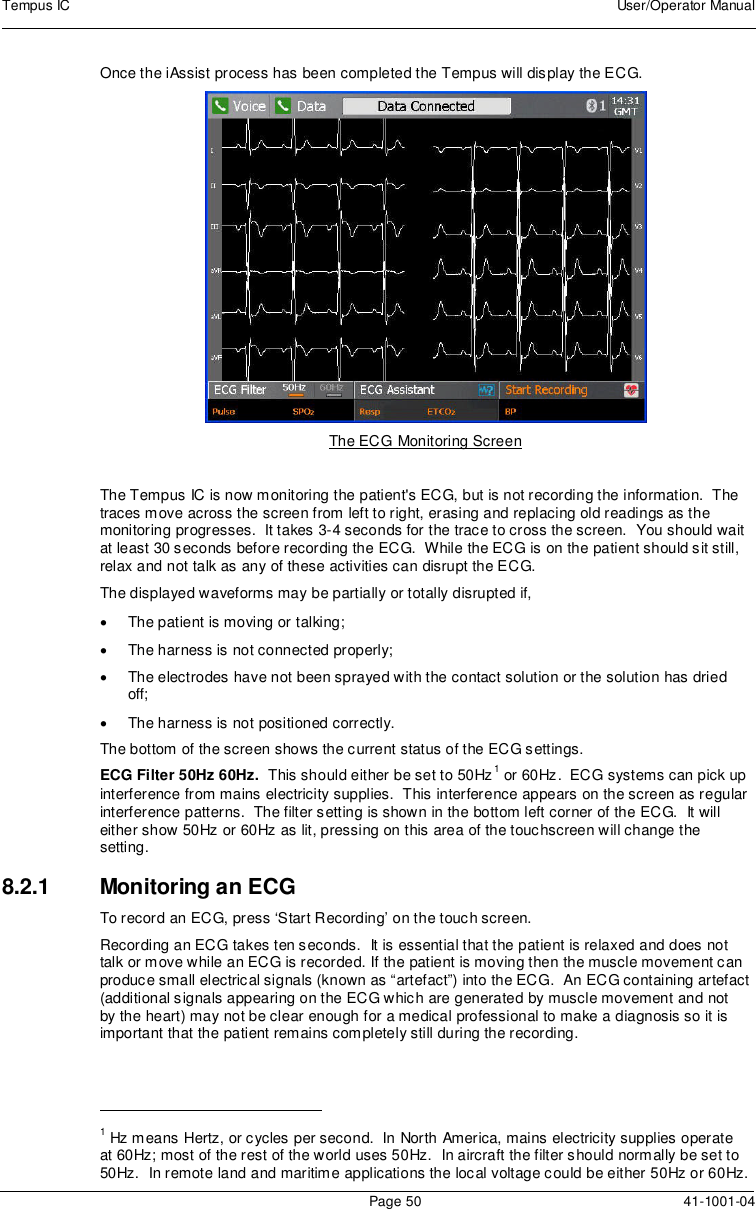
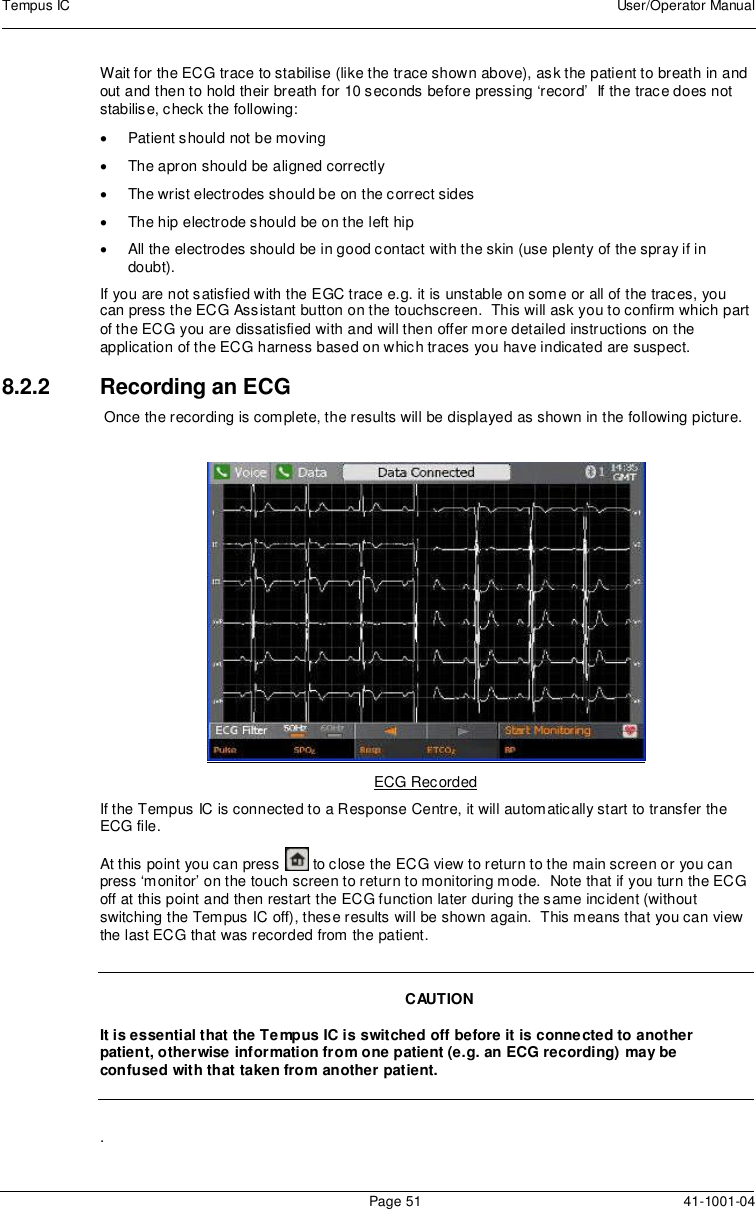
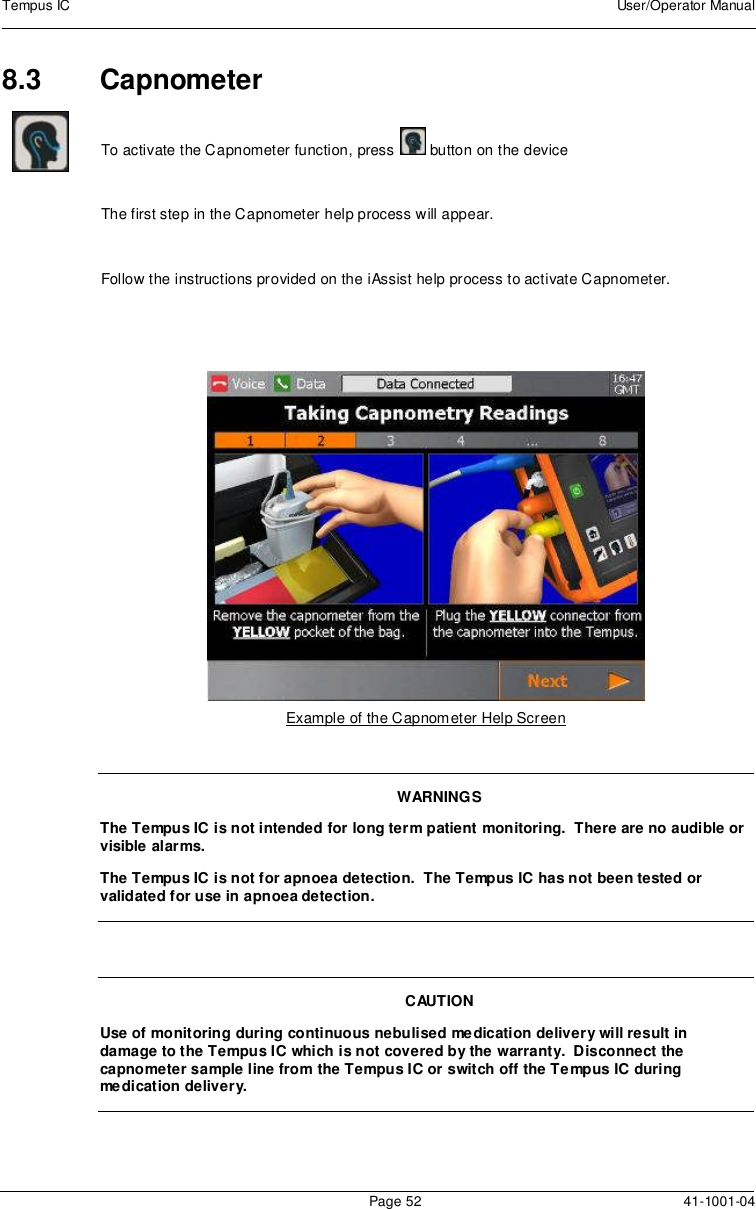

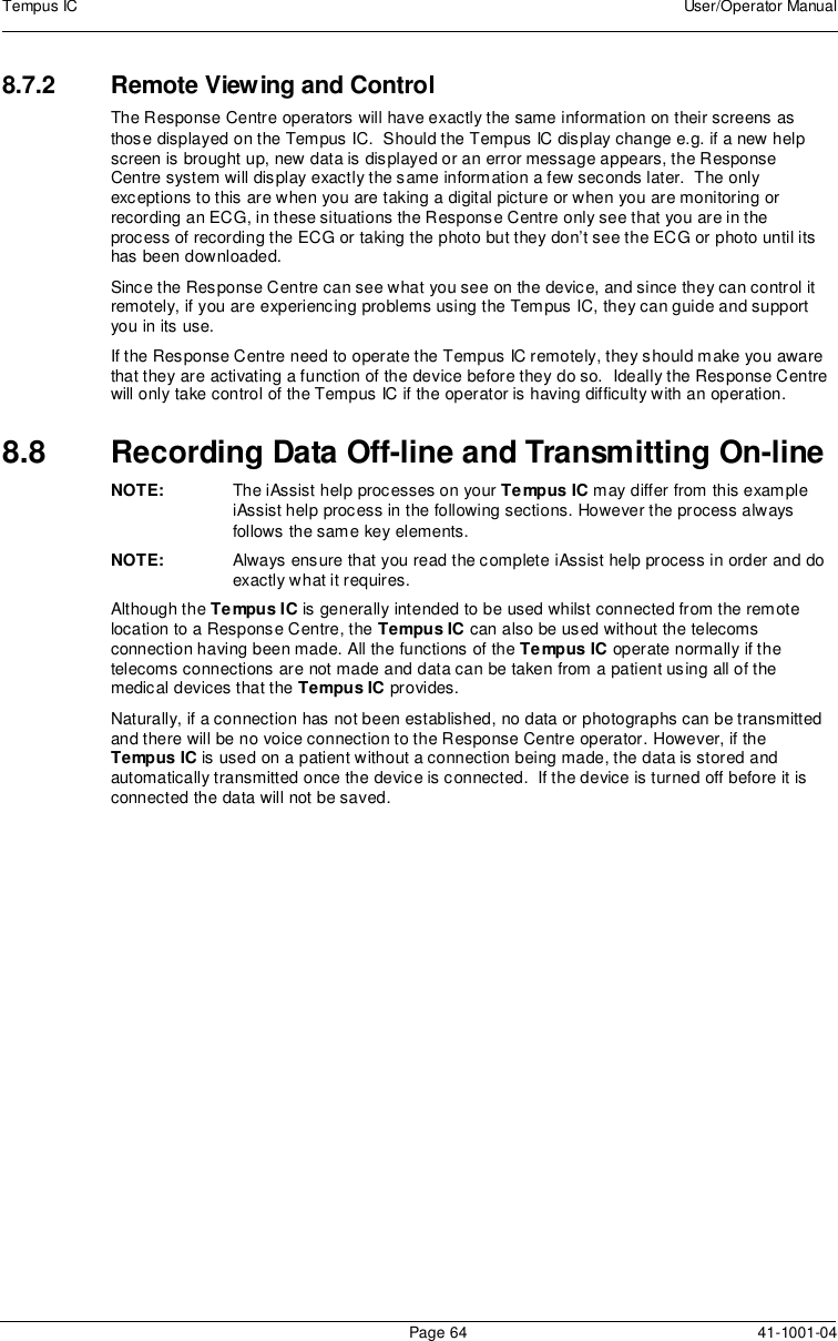
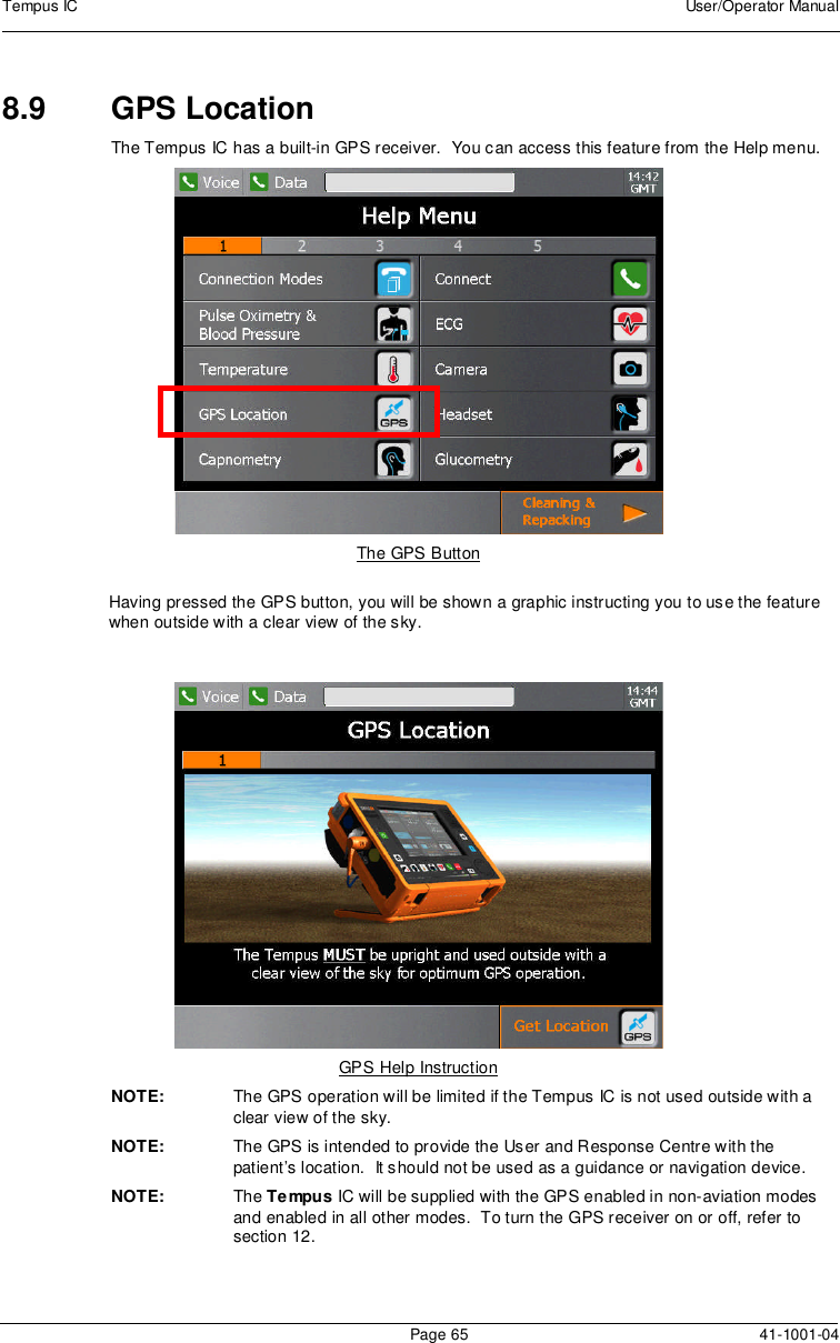
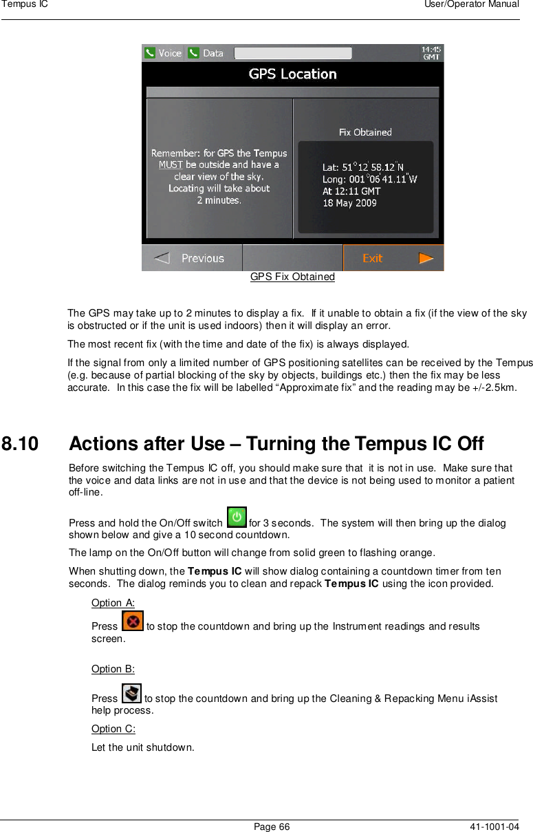
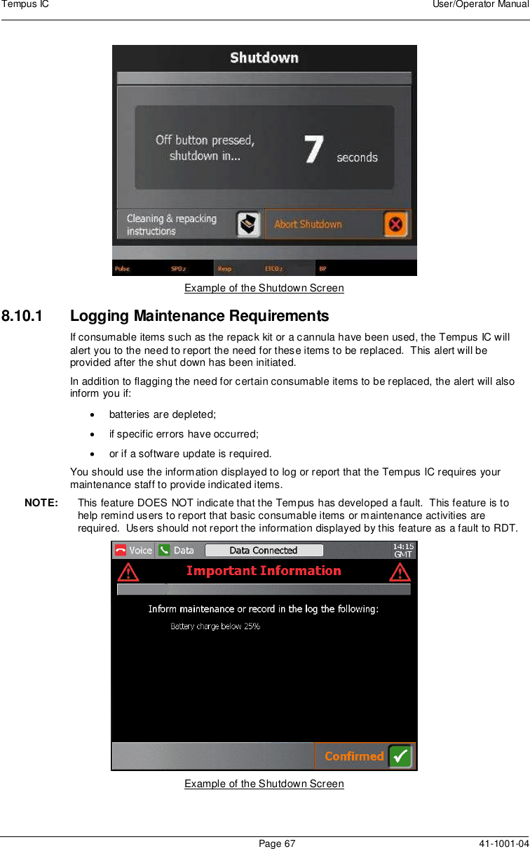
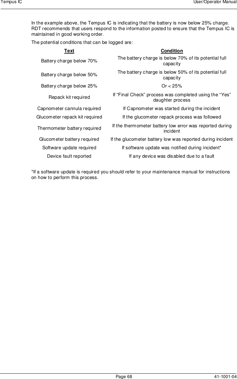
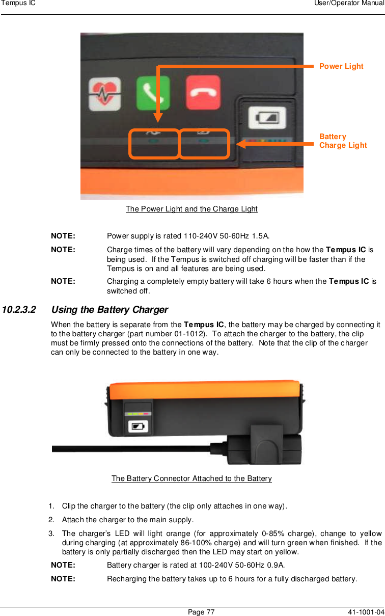
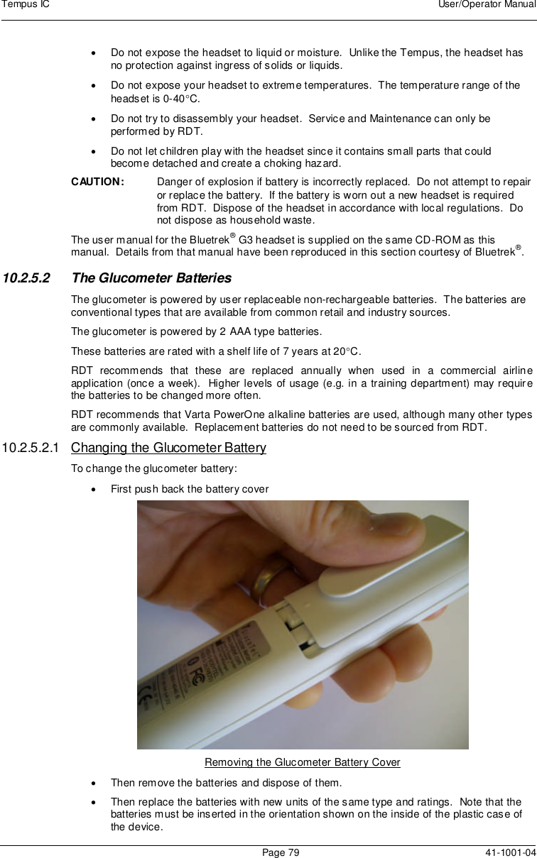
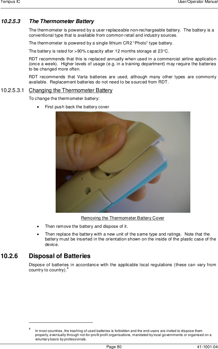
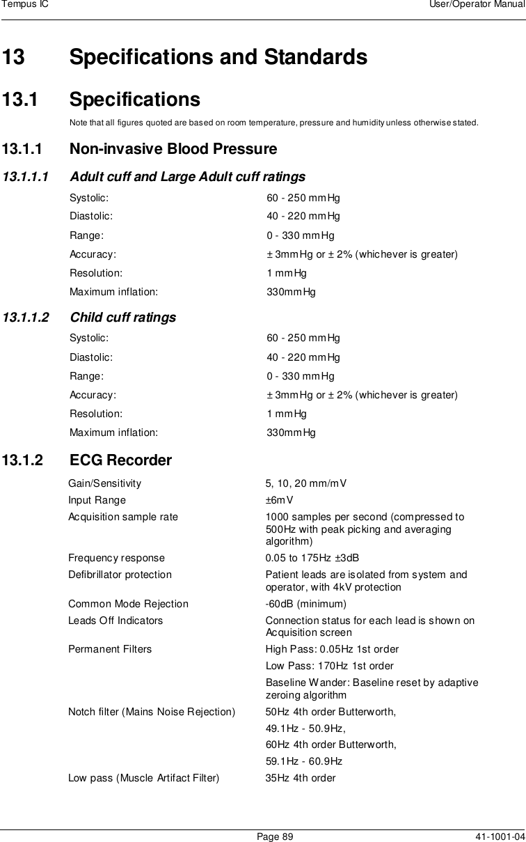
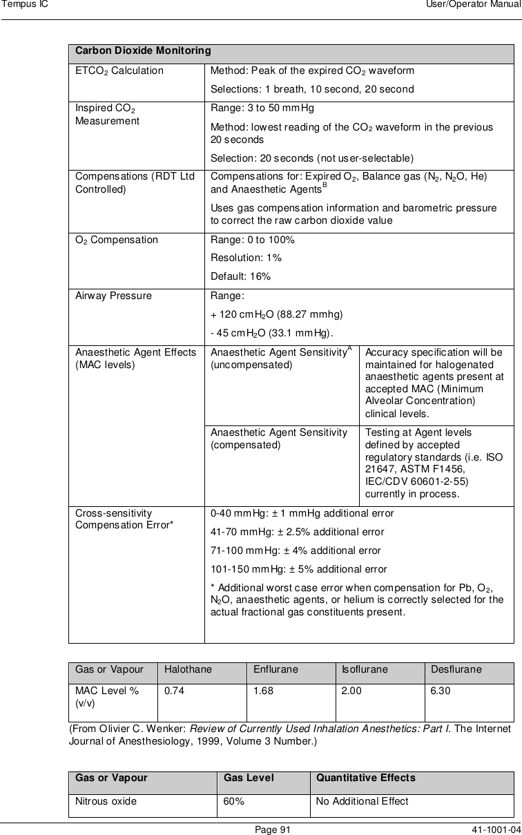
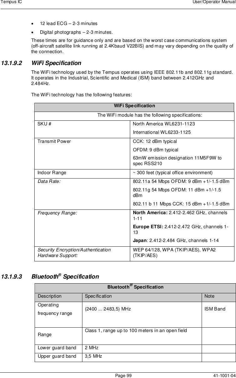
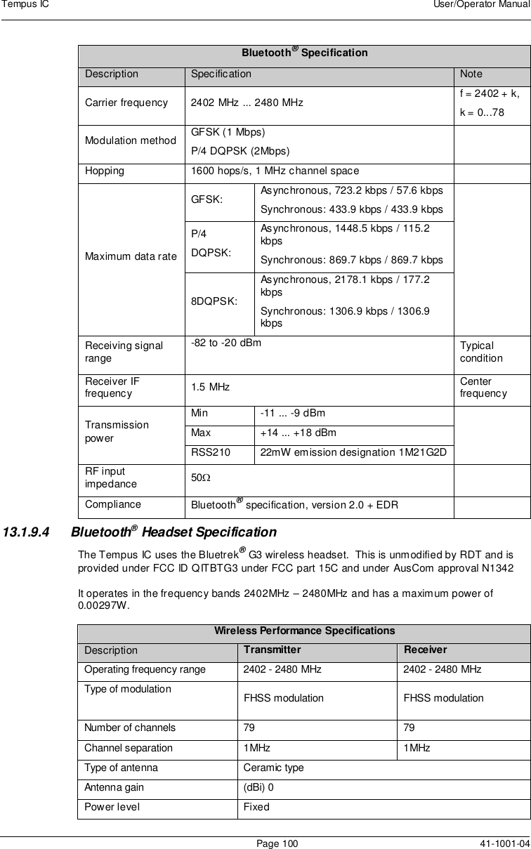
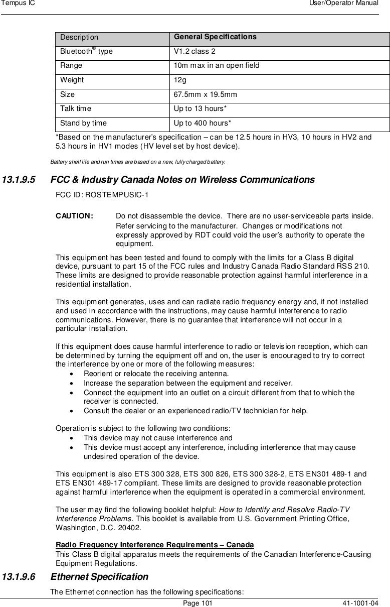
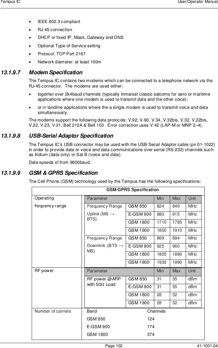
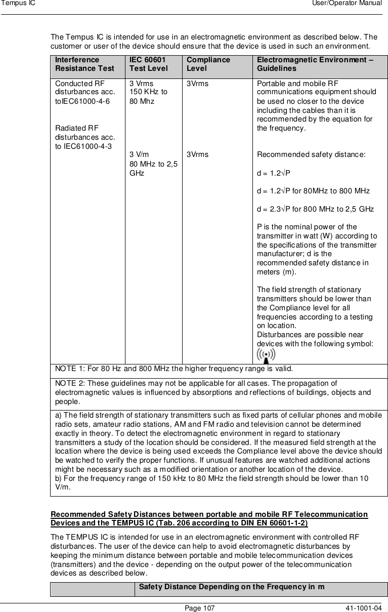
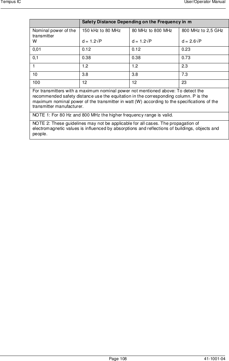
![Tempus IC User/Operator ManualPage 90 41-1001-0413.1.3 ETC02SensorUnless otherwise stated, all CO2measurements are made following an airway adapter zero,with 5% CO2gas, balance N2at 25 degrees C, and Pb = 760 mmHg with 2 litres per minuteflow. The stabilization time for full specification testing of the LoFlo Module over the entiretemperature range is 20 minutes.Range: 0-100 BPMAccuracy: ± 2 BPMRange: 0-10% CO2 displayed valueAccuracy: ± 4%Rise time: <2 secondsDelay time: 5 secondsOperating altitude range: 0-15000 feetThe capnometer is automatically compensated for local atmospheric pressure.Physical characteristics: Module weight is less than 9.6 oz (272.16 g)Module Size: < 2.6" wide x 1.5" high x 3.5" deep [<66.0 x 38.1 x 88.9 mm]Cable length – 19 inches (46 cm)Carbon Dioxide MonitoringMode of Sampling SidestreamPrinciple of Operation Non-dispersive infrared (NDIR) single beam optics, dualwavelength, no moving parts.Initialization Time Measurement displayed in less than 20 seconds, At anambient temperature of 25° C, full specifications within 2minutes.CO2Measurement Range 0 to 150 mmHg 0 to 19.7% 0 to 20 kPa (Barometric Pressuresupplied by RDT Ltd)CO2Calculation Method BTPS (Body Temperature Pressure Saturated)CO2Response Time <3 seconds - includes transport time and rise timeCO2Resolution 0.1 mmHg 0 to 69 mmHg 0.25 mmHg 70 to 150 mmHgCO2Accuracy * 0 - 40 mmHg ± 2 mmHg41 - 70 mmHg ± 5% of reading71 - 100 mmHg ± 8% of reading101 - 150 mmHg ± 10% of readingAbove 80 breath per minute ± 12% of reading* NOTE: Gas temperature at 25° C.CO2Stability Short Term Drift: Drift over four hours shall not exceed 0.8mmHg maximum. Long Term Drift: Accuracy specification willbe maintained over a 120 hour period.CO2Noise RMS noise of the sensor shall be less than or equal to 0.25mmHg at 5% CO2Sampling Rate 100 HzRespiration Rate Range 2 to 150 breaths per minute (BPM)Respiration RateAccuracy ± 1 breathCalibration No routine user calibration required.](https://usermanual.wiki/Remote-Diagnostic-Technologies/TEMPUSIC-1/User-Guide-1250058-Page-91.png)