Renishaw plc MI16-433 RECEIVER FOR MACHINE TOOLS TELEMETRY RX User Manual RMP3 433 USER GUIDE
Renishaw plc RECEIVER FOR MACHINE TOOLS TELEMETRY RX RMP3 433 USER GUIDE
UserManual.wiki
>
Renishaw plc
>
MI16 433 User Manual
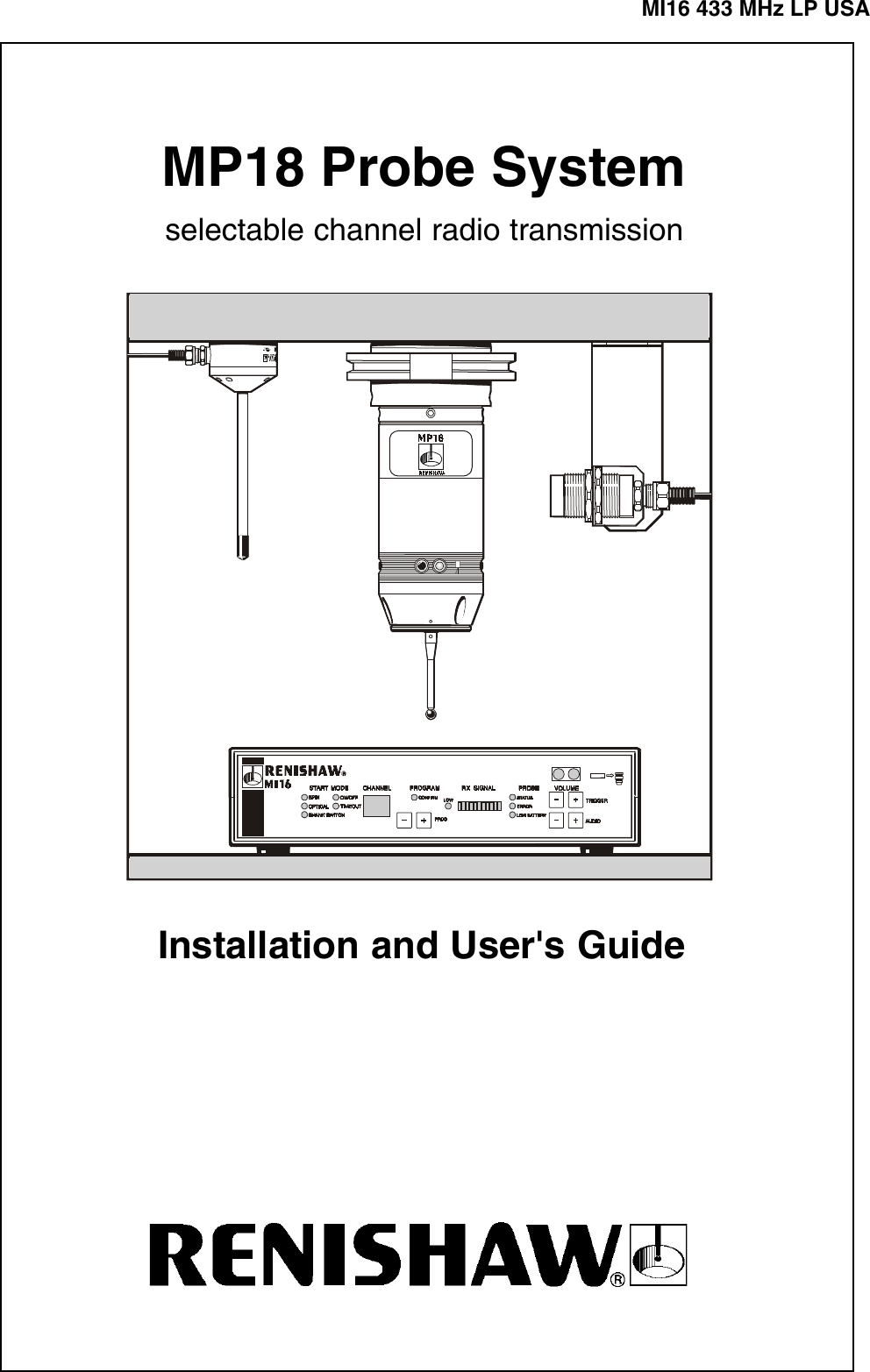
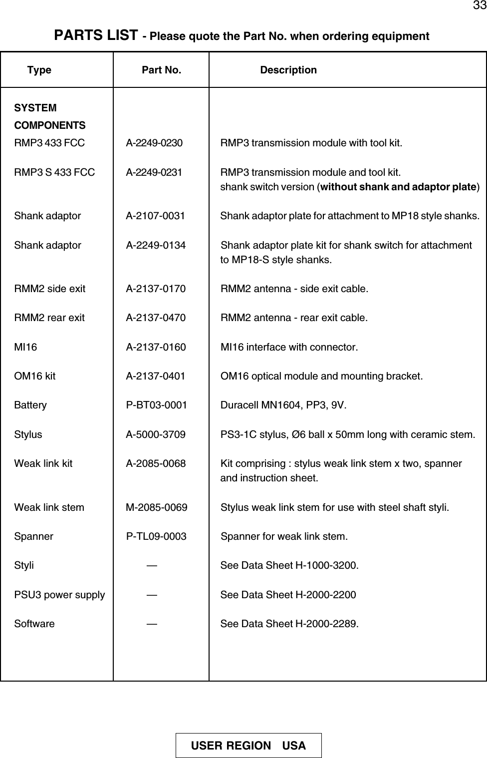
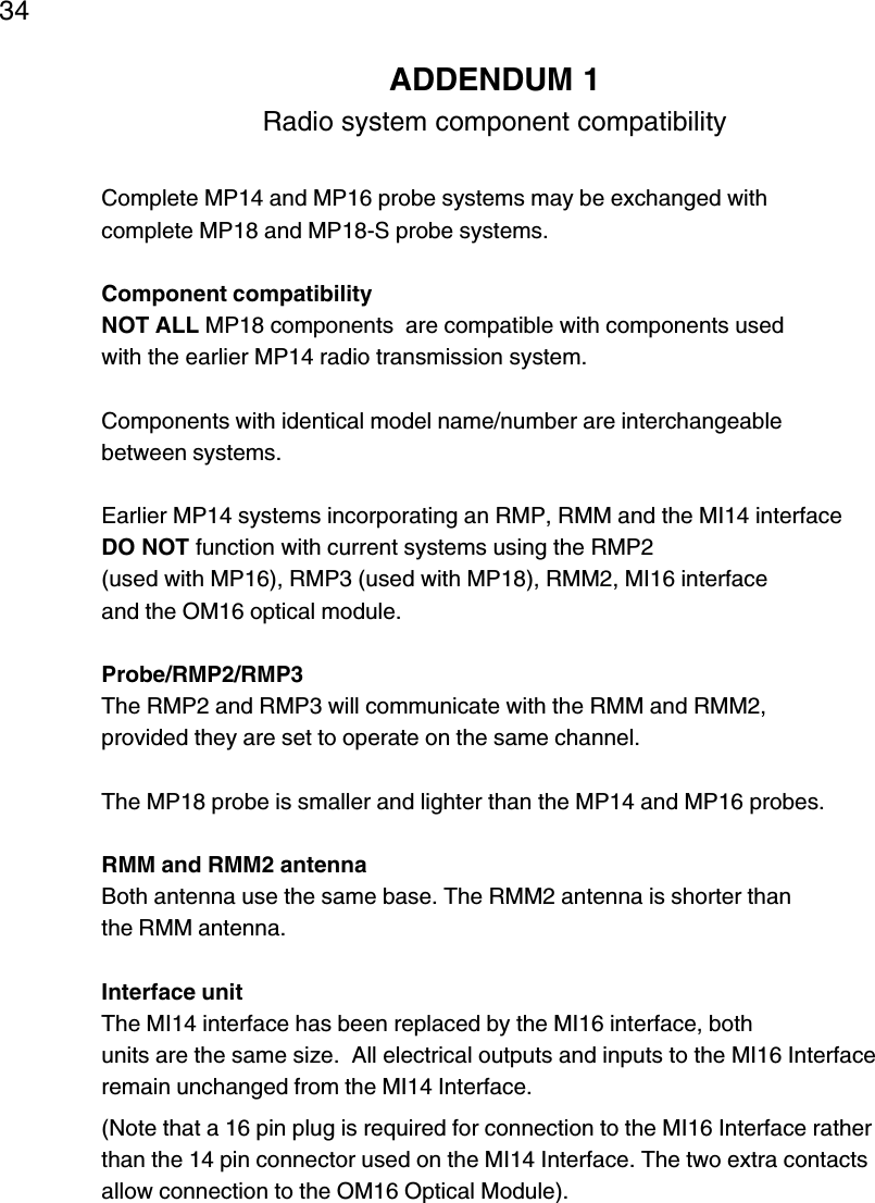
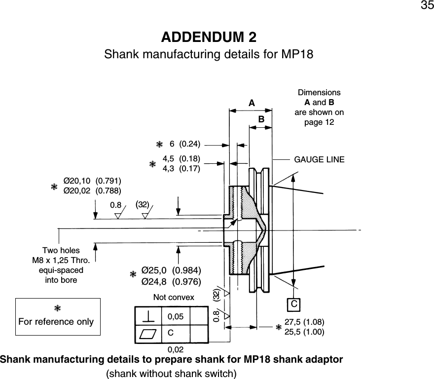
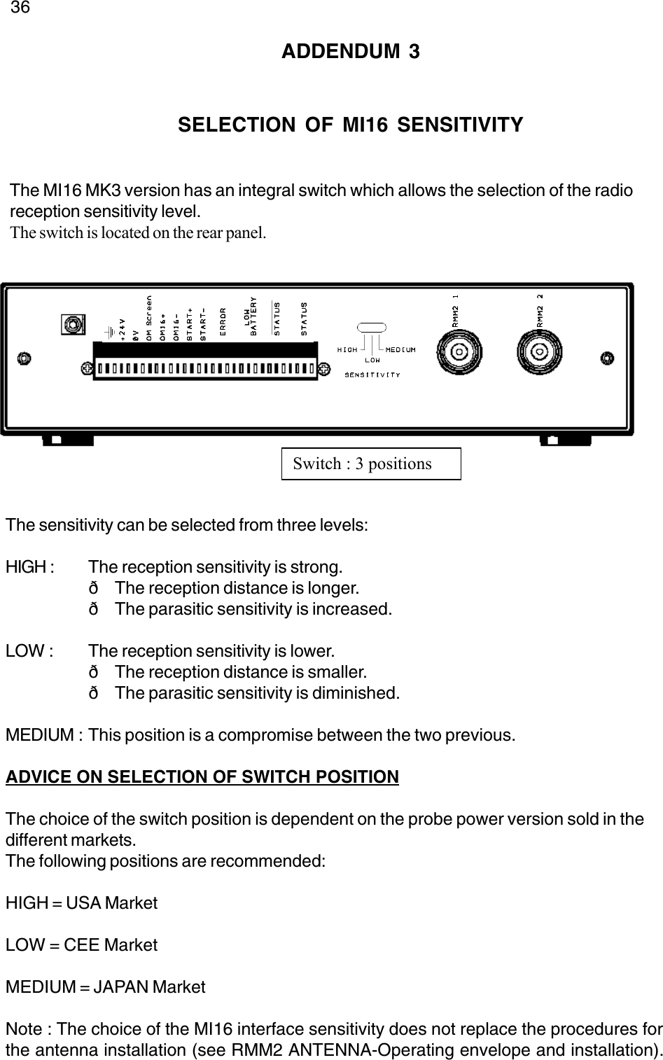
USER GUIDE
Navigation menu
Upload a User Manual
Namespaces
Wiki Guide
HTML
PDF
Info
Views
User Manual
Discussion / Help
Navigation
![Renishaw reserves the right to change specifications without notice.Renishaw plc, New Mills, Wotton-under-Edge, Gloucestershire, GL12 8JR, United Kingdom.International Tel +44 1453 524 524 National Tel 01453 524 524 [07000 RENISHAW]International Fax +44 1453 524 901 National Fax 01453 524 901Telex 437120 RENMET G email genenq@renishaw.comGROUP COMPANIESRenishaw LatinoAmericana Ltda.,Calçada dos Crisântemos 22,C.C. Alphaville,C.e.p. 06453-000, Barueri SP,Brazil.Tel +55 11 7295 2866Fax +55 11 7295 1641email brazil@renishaw.comRenishaw (Hong Kong) Ltd.,Unit 4A, 3/F, New Bright Building,11 Sheung Yuet Road,Kowloon Bay,Hong Kong.The People’s Republic of China.Tel +852 2753 0638Fax +852 2756 8786email hongkong@renishaw.comRenishaw S.A.,15 rue Albert Einstein,Champs sur Marne,77437 Marne la Vallée,Cedex 2,France.Tel +33 1 64 61 84 84Fax +33 1 64 61 65 26email france@renishaw.comRenishaw GmbH,Karl-Benz Strasse 12,72124 Pliezhausen,Germany.Tel +49 7127 9810Fax +49 7127 88237emailgermany@renishaw.comRenishaw S.p.A.,Via dei Prati 5,10044 Pianezza,Torino,Italy.Tel +39 011 9 66 10 52Fax +39 011 9 66 40 83email italy@renishaw.comRenishaw KK,Across City Nakano-Sakaue,38-1, Chuo 1-chome,Nakano-ku,Tokyo 164-0011,Japan.Tel+81 3 5332 6021Fax +81 3 5332 6025email japan@renishaw.comRenishaw Iberica S.A.,Edificio Océano,Calle Garrotxa 10-12,Parque Más Blau,08820 Prat de LLobregat,Barcelona,Spain.Tel +34 93 478 21 31Fax +34 93 478 16 08email spain@renishaw.comRenishaw A.G.,Poststrasse 5,CH 8808 Pfäffikon,Switzerland.Tel +41 55 410 66 66Fax +41 55 410 66 69email switzerland@renishaw.comRenishaw Inc.,5277 Trillium Blvd,Hoffman Estates, Illinois 60192,U.S.A.Tel +1 847 843 3666Fax +1 847 843 1744email usa@renishaw.comREPRESENTATIVE OFFICESAustralia Tel +61 3 9553 8267Melbourne Fax +61 3 9592 6738email australia@renishaw.comThe People’s Republic of ChinaBeijing Tel +86 10 6410 7993Fax +86 10 6410 7992email china@renishaw.comIndonesia Tel +62 21 428 70153Jakarta Fax +62 21 424 3934email indonesia@renishaw.comSingapore Tel +65 897 5466Fax +65 897 5467email singapore@renishaw.comREPRESENTATIVE OFFICESTaiwan Tel +886 4 251 3665Taichung city Fax +886 4 251 3621email taiwan@renishaw.comIndia Tel +91 80 509 5419Bangalore Fax +91 80 509 5421email india@renishaw.comLIAISON OFFICESouth Korea Tel +82 2 565 6878Seoul Fax +82 2 565 6879email southkorea@renishaw.comwww.renishaw.com© Renishaw 2000 Issue date 09.00](https://usermanual.wiki/Renishaw-plc/MI16-433/User-Guide-254625-Page-37.png)