Renishaw plc MI16-433 RECEIVER FOR MACHINE TOOLS TELEMETRY RX User Manual RMP3 433 USER GUIDE
Renishaw plc RECEIVER FOR MACHINE TOOLS TELEMETRY RX RMP3 433 USER GUIDE
USER GUIDE
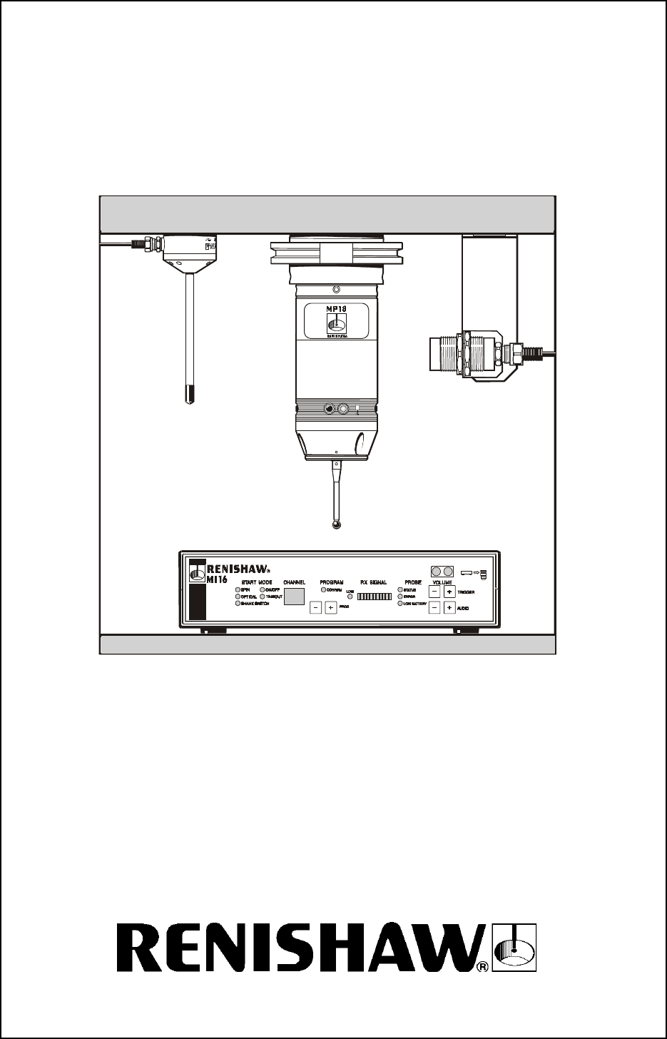
MI16 433 MHz LP USA
MP18 Probe System
selectable channel radio transmission
Installation and User's Guide

2
PATENTS
Features of the MP18 Probe With Channel Selectable Radio Transmission are the
subject of the patents and patent applications listed below :
EP 108521 JP 326, 001/1992 US 4, 599, 524
EP 501680 JP 89, 397/1993 US 4, 636, 960
EP 506318 JP 1, 847, 335 US 4, 636, 960
EP 652413 JP 1, 942, 442 US 5, 272, 817
FCC DECLARATION USA
FCC ID: K
Q
G MI16-433

3
FCC DECLARATION (USA)
FCC Section 15.19
This device complies with Part 15 of the
FCC rules.
Operation is subject to the following two
conditions:
1. This device may not cause harmfull
interference.
2. This device must accept any interference
received, including interference that may
cause undesired operation.
FCC Section 15.105
This equipment has been tested and
found to comply with the limits for a
Class A digital device, pursuant to Part 15
of the FCC rules.
These limits are designed to provide
reasonable protection against harmful
interference when the equipment
is operated in a commercial environment.
This equipment generates, uses, and can
radiate radio frequency energy and,
This product has been tested to the following European Standards
I-ETS 300 220 (October 1993)
ETS 300 683 (June 1997)
if not installed and used in accordance
with the instruction manual, may cause
harmful interference to radio communications.
Operation of this equipment in a residential
area is likely to cause harmful interference,
in which case you will be required to correct
the interference at your own expense.
FCC Section 15.21
The user is cautioned that any changes
or modifications not expressly approved
by Renishaw plc, or authorised
representative could void the user's
authority to operate the equipment.
FCC Section 15.27
The user is also cautioned that any peripheral
device installed with this equipment such as a
computer, must be connected with a high
quality shielded cable to insure compliance
with FCC limits.
4
GB SAFETY
Beware of unexpected movement. The user should remain outside
of the full working envelope of probe head/extension/probe combinations.
Handle and dispose of batteries according to the manufacturer’s
recommendations. Use only the recommended batteries.
Do not allow the battery terminals to contact other metallic objects.
For instructions regarding the safe cleaning of Renishaw products,
refer to the Maintenance section of the relevant product documentation.
Remove power before performing any maintenance operations.
Refer to the machine supplier’s operating instructions.
The unit must be supplied from a 24V DC SELV supply complying with
the essential requirements of BS EN 61010 or similar specification.
D SICHERHEITSANWEISUNGEN
Auf unerwartete Bewegungen achten. Der Anwender soll sich immer
außerhalb des Meßtasterkopf-Arm-Meßtaster-Bereichs aufhalten.
Batterien immer gemäß den Anleitungen des Herstellers handhaben und
diese vorschriftsmäßig entsorgen. Nur die empfohlenen Batterien
verwenden. Die Batterieklemmen nicht in Kontakt mit metallischen
Gegenständen bringen.
Anleitungen über die sichere Reinigung von Renishaw-Produkten sind in
Kapitel MAINTENANCE (WARTUNG) in der Produktdokumentation
enthalten.
Bevor Wartungsarbeiten begonnen werden, muß erst die Stromversorgung
getrennt werden.
Beziehen Sie sich auf die Wartungsanleitungen des Lieferanten.
Die Einheit muß von einer Schutzkleinspannungsversorgung mit 24V DC
gespeist werden, die den wesentlichen Anforderungen von BS EN 61010
oder einer ähnlichen Norm entspricht.
DK SIKKERHED
Pas på uventede bevægelser. Brugeren b¢r holde sig uden for hele
sondehovedets/ forlængerens/ sondens arbejdsområde.
Håndtér og bortskaf batterier i henhold til producentens anbefalinger.
Anvend kun de anbefalede batterier. Lad ikke batteriterminalerne
komme i kontakt med andre genstande af metal.
Se afsnittet MAINTENANCE (VEDLIGEHOLDELSE)
i produktdokumentationen for at få instruktioner
til sikker reng¢ring af Renishaw-produkter.
Afbryd str¢mforsyningen, f¢r der foretages vedligeholdelse.
Se maskinleverand¢rens brugervejledning.
Enheden skal forsynes fra en 24 V d.c. SELV (Separat ekstra lav spænding)
netspænding, der efterlever de vigtige krav i BS EN 61010 eller lignende
specifikation.
5
E SEGURIDAD
Tener cuidado con los movimientos inesperados. El usuario debe quedarse
fuera del grupo operativo completo compuesto por la cabeza de sonda/
extensión/sonda o cualquier combinación de las mismas.
Las baterías deben ser manejadas y tiradas según las recomendaciones
del fabricante. Usar sólo las baterías recomendadas. No permitir que los
terminales de las mismas entren en contacto con otros objetos metálicos.
Para instrucciones sobre seguridad a la hora de limpiar los productos
Renishaw, remitirse a la sección titulada MAINTENANCE
(MANTENIMIENTO) en la documentación sobre el producto.
Quitar la corriente antes de emprender cualquier operación de
mantenimiento.
Remitirse a las instrucciones de manejo del proveedor de la máquina.
La unidad debe de ser alimentada desde un alimentador .V c.c. SELV
(Tensión Extra Baja Separada) que cumpla con los requisitos esenciales
de BS EN 61010 o una especificación similar.
F SECURITE
Attention aux mouvements brusques. L’utilisateur doit toujours rester
en dehors de la zone de sécurité des installations multiples tête de
palpeur/rallonge/palpeur.
Suivre les conseils du fabricant pour manipuler et jeter les batteries.
Utiliser uniquement les batteries recommandées. Veiller à ce que les
bornes de la batterie n’entrent pas en contact avec d’autres objets
métalliques.
Les conseils de nettoyage en toute sécurité des produits Renishaw
figurent dans la section MAINTENANCE de votre documentation.
Mettre la machine hors tension avant d’entreprendre toute opération
de maintenance.
Consulter le mode d’emploi du fournisseur de la machine.
L’appareil doit être alimenté par un courant continu de 24V SELV
(voltage ultra-faible séparé), conformément aux exigences primordiales
de la norme BS EN 61010 ou d’une spécification semblable.
FIN TURVALLISUUTTA
Varo äkillistä liikettä. Käyttäjän tulee pysytellä täysin anturin pään/jatkeen/
anturin yhdistelmiä suojaavan toimivan kotelon ulkopuolella.
Käytä paristoja ja hävitä ne valmistajan ohjeiden mukaisesti.
Käytä ainoastaan suositeltuja paristoja. Älä anna paristonapojen koskettaa
muita metalliesineitä.
Renishaw-tuotteiden turvalliset puhdistusohjeet löytyvät tuoteselosteen
MAINTENANCE (HUOLTOA) koskevasta osasta.
Kytke pois sähköverkosta ennen huoltotoimenpiteitä.
Katso koneen toimittajalle tarkoitettuja käyttöhjeita.
Laite virta on kytkettävä 24V d.c. SELV (Separated Extra Low
Voltage - Erotettu erityisen alhainen jännite) -virtaverkkoon standardin
BS EN 61010 tai vastaavan spesifikaation asettamien perusvaatimusten

6
GR
I SICUREZZA
Fare attenzione ai movimenti inaspettati. Si raccomanda all’utente di tenersi
al di fuori dell’involucro operativo della testina della sonda, prolunghe e altre
varianti della sonda.
Trattare e smaltire le pile in conformità alle istruzioni del fabbricante.
Usare solo pile del tipo consigliato. Evitare il contatto tra i terminali delle
pile e oggetti metallici.
Per le istruzioni relative alla pulizia dei prodotti Renishaw, fare riferimento
alla sezione MAINTENANCE (MANUTENZIONE) della documentazione
del prodotto.
Prima di effettuare qualsiasi intervento di manutenzione, isolare
dall’alimentazione di rete.
Consultare le istruzioni d’uso del fabbricante della macchina.
L’unità deve essere alimentata da un’alimentazione di 24V C.C.
(Tensione Bassa Separata Extra) conforme agli essenziali requisiti
della NS EN 61010 o analoghe specifiche.
NL VEILIGHEID
Oppassen voor onverwachte beweging. De gebruiker dient buiten het
werkende signaalveld van de sondekop/extensie/sonde combinaties
te blijven.
De batterijen volgens de aanwijzingen van de fabrikant hanteren en wegdoen.
Gebruik uitsluitend de aanbevolen batterijen. Zorg ervoor dat de poolklemmen
niet in contact komen met andere metaalhoudende voorwerpen.
Voor het veilig reinigen van Renishaw produkten wordt verwezen naar het
hoofdstuk MAINTENANCE (ONDERHOUD) in de produktendocumentatie.
Voordat u enig onderhoud verricht dient u de stroom uit te schakelen.
De bedieningsinstructies van de machineleverancier raadplegen.
De stroomtoevoer naar de eenheid moet gebeuren via een 24V gelijkstroom
SELV (Separated Extra Low Voltage - Afzonderlijke extra lage spanning)
voeding, overeenkomstig de belangrijkste vereisten van de Britse norm
BSEN61010 of een gelijksoortige standaard.
7
P SEGURANÇA
Tomar cuidado com movimento inesperado. O utilizador deve permanecer
fora do perímetro da área de trabalho das combinações cabeça da sonda/
extensão/sonda.
Manusear e descartar baterias de acordo com as recomendações do
fabricante. Utilizar apenas as baterias recomendadas. Não permitir que os
terminais da bateria entrem em contacto com outros objectos metálicos.
Para instruções relativas à limpeza segura de produtos Renishaw, consultar
a secção MAINTENANCE (MANUTENÇÃO) da documentação do produto.
Desligar a alimentação antes de efectuar qualquer operação de
manutenção.
Consultar as instruções de funcionamento do fornecedor da máquina.
A unidade deve ser abastecida de um abastecimento SELV (Separated
Extra Low Voltage) (baixa voltagem extra separada) de 24 V. c.d., em
conformidade com os requisitos essenciais da norma BS EN 61010 ou de
outra especificação semelhante.
SW SÅKERHET
Se upp för plötsliga rörelser. Användaren bör befinna sig utanför
arbetsområdet för sondhuvudet/förlängningen/sond-kombinationerna.
Hantera och avyttra batterier i enlighet med tillverkarens rekommendationer.
Använd endast de batterier som rekommenderas.
Låt ej batteriuttagen komma i kontakt med andra metallföremål.
För instruktioner angående säker rengöring av Renishaws produkter,
se avsnittet MAINTENANCE (UNDERHÅLL) i produktdokumentationen.
Koppla bort strömmen innan underhåll utförs.
Se maskintillverkarens bruksanvisning.
Enheten måste strömförsörjas från en SELV-källa (Separated Extra Low
Voltage - Separat extra låg spänning) på 24 volt likström, som uppfyller
huvudkraven i BS EN 61010, eller motsvarande specifikation.
8SYSTEM DESCRIPTION
System description… … … … … … … … 9
Features … … … … … … … … … 9
System operation … … … … … … … … 9
System components … … … … … … … 10
System specification … … … … … … … 11
MP18 and MP18-S PROBES
MP18 probe/shank … … … … … … … … 12
MP18-S probe/shank … … … … … … … 13
MP18 probe/shank assembly … … … … … 14
MP18 stylus on centre adjustment … … … … … 14
MP18-S stylus on centre adjustment … … … … 15
RMM2 ANTENNA
Operating envelope and installation … … … … … 16
MI16 INTERFACE
MI16 front panel … … … … … … … … 18
MI16 rear panel … … … … … … … … 19
MI16 audio diagnostics … … … … … … … 20
MI16 output waveforms … … … … … … … 20
MI16 panel mounting kit … … … … … … 20
PSU3 POWER SUPPLY UNIT …… …… … 21
OM16 OPTICAL MODULE ………………22
MI18 BATTERY POWER ………………24
MODES OF OPERATION ………………25
MODE AND CHANNEL SELECTION …… …… … 26
PROGRAMMING THE MI16 INTERFACE …………26
RADIO FREQUENCY AND CHANNEL SEPERATION ……27
PROGRAMMING THE PROBE RMP3 MODULE …… … 28
MAINTENANCE
Stylus spring pressure adjustment … … … … … 29
Diaphragm inspection and replacement … … … … 30
Screw torque values … … … … … … … 31
PARTS LIST … … … … … … … … 32-33
ADDENDUM 1 - compatibility with other systems … … … 34
ADDENDUM 2 - shank manufacture for MP18 … … … 35
ADDENDUM 3 - selection of MI16 sensitivity ... ... ... 36
CONTENTS
Page No.
9
The MP18 Probe is used for job set up and workpiece measurement
on CNC machine tools. Signal transmission between transmitters and
recievers is non line of sight. The radio channel is selectable and signal
transmission range is up to distances of 3m (9.8ft).
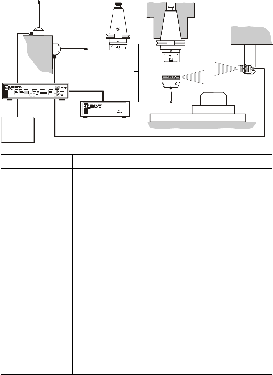
SYSTEM DESCRIPTION
SYSTEM OPERATION
The probe assembly is stored in the machine
tool changer as any other tool, and is transferred
to the machine spindle for probing routines.
The probe head acts as an omni-directional switch
and is effective in the ± X, ±Y and +Z directions.
During operation, the probe stylus is driven
against a workpiece feature. On contact the radio
module probe (RMP3) transmits a probe signal to
the two radio modules machine (RMM2), using
frequency modulated (FM) radio waves.
The signal then passes via cable to the MI16
interface and onto the CNC machine control,
thereby recording the stylus contact position in
the machine tool registers. Two different contact
positions enable features to be measured.
Probing software is available from Renishaw
FEATURES
●Transmission of the probe trigger
signal using FM radio transmission
at 433MHz frequency.
●User selection of the transmission
channel (up to 69 available),
permits many systems to operate
in close proximity, with no
interference between systems.
●Switch on - switch off mode.
●Two receivers to provide cover for
signal transmission dead spots.
●M code switch on and off of the probe,
using an optional optical transmitter
module (OM16).
10
RMM2 x 2
radio module machine
PSU3 power supply unit
optional
MI16
interface unit
MP18-S
typical
shank
OM16
optical
module
optional
Shank
switch
MP18
probe
Shank
adaptor
RMP3
radio
module
probe
Probe
head
SYSTEM COMPONENTS
Machine spindle
Workpiece
Machine table
MP18
typical
shank
Probe head + RMP3 radio module probe + shank adaptor for MP18.
Probe ready shanks are available from Renishaw.
Probe head + RMP3 radio module probe + shank adaptor for MP18 -S.
Custom shanks are supplied on application to Renshaw Custom
Products Department. MP18-S shanks incorporate a shank switch
which switches the probe on, when it is placed in the machine spindle.
Probe to shank adaptor plate (Part No. A-2107-0031).
Probe to shank adaptor plate (Part No. A-2249-0134).
Radio Module Machine - transmits and receives signals
between machine control and Radio Module Probe (RMP3).
Signals received by the RMM2, pass via coaxial cable to the MI16
machine interface, which decodes and converts them into solid state
relay (SSR) outputs for use by the machine tool’s CNC controller.
An M code causes the OM16 optical transmission module, to send
probe switch on/off signal to the RPM3.
The MI16 draws 24V DC power from the CNC machine and presents
a load of up to 500mA. If this supply is not available from the machine
power can be supplied by a Renishaw PSU3 power supply unit.
MP18 probe
Shank for MP18
MP18-S probe
Shank for MP18-S
MP18 shank adaptor
MP18-S shank adaptor
RMM2 with side
or rear cable exit
MI16
machine interface
OM16 - optional
optical module
PSU3 - optional
power supply unit
COMPONENT DESCRIPTION
CNC
machine
control
11
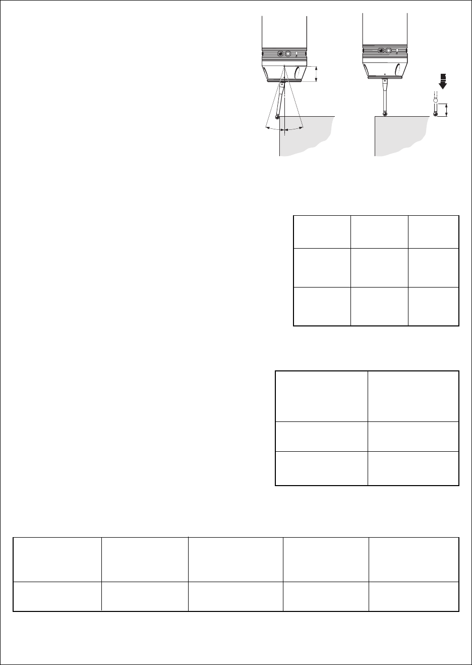
SPECIFICATION
dimensions mm (in)
PROBE REPEATABILITY
Maximum 2 Sigma (2σσ
σσ
σ) Value
Repeatability of 1,0µm (0.00004in) is valid for
test velocity of 480mm/min (1.57ft/min) at
stylus tip, using stylus 50mm (1.97in) long.
SENSE DIRECTIONS and
STYLUS TRIGGER FORCE
Set at factory using stylus 50mm (1.97in) long.
X and Y trigger forces vary around the stylus
seating.
X and Y direction - lowest force 0,75N
75gf
(2.64oz)
X and Y direction - highest force 1,4N
140gf
(4.92oz)
Z direction force 4,9N
490gf
(17.28oz)
PROBE SEALING
IPX8 (BS 5490, IEC 529) 100kPa
(1 atmosphere).
SYSTEM DELAYS
The time delay from the probe stylus contacting
the workpiece, and the MI16 machine interface
providing an output signal to the CNC controller
is 12ms ±10µs.
STYLUS OVERTRAVEL LIMITS
21,5mm
(0.85in)
Z
X/Y
17.5° 17.5°
Stylus
length
50mm
(1.96in)
100mm
(3.93in)
X - Y
21,5mm
(0.84in)
36,5mm
(1.43in)
Z
8mm
(0.31in)
8mm
(0.31in)
TEMPERATURE
PROBE/RMP3
RMM2
MI16 INTERFACE
OM16
ENVIRONMENT
Region
USA
RADIO FREQUENCIES and TRANSMISSION RANGE
.
Nominal
transmission
frequency
433 MHz
Number of
transmission
channels
69
Channel
separation
25 KHz
Transmission
range
3m (9.8ft)
Storage -20°C to 60°C
(-4°F to 140°F)
Operating 0°C to 40°C
(32°F to 104°F)
12
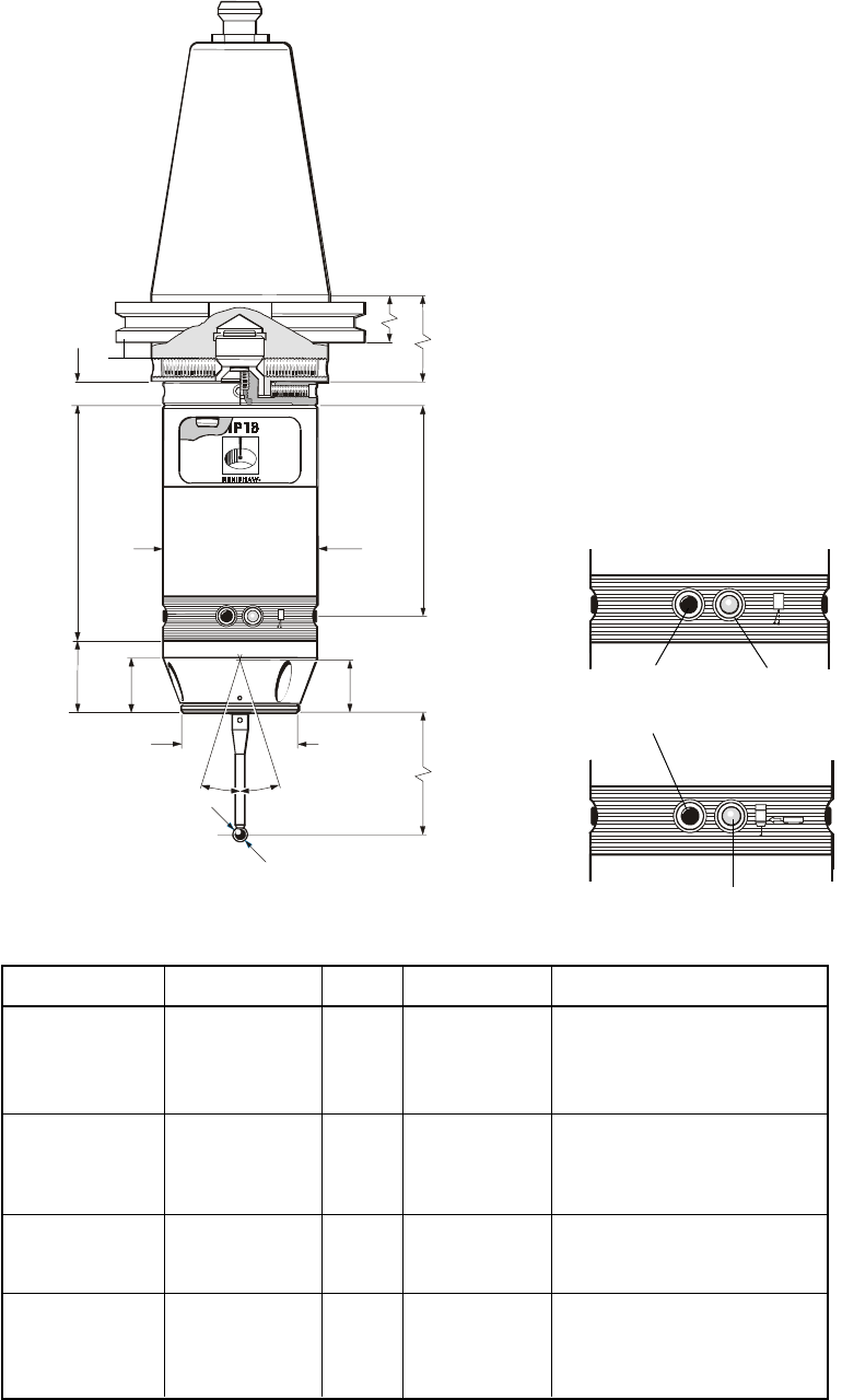
MP18
dimensions mm (in)
BA
9mm
(0.35in)
TAPER SHANK
The shank is attached to the
RMP3 using a shank adaptor.
Part No. A-2107-0031.
The method of attachment
is the same as used for other
Renishaw probes (MP7, MP8,
MP9 and MP10 compact
optical probes).
Shank assembly is shown
on page 14.
Probe ready shanks are
available from Renishaw.
Shank modification details for
shanks obtained from other
sources are given on page 35.
These shanks are not suitable for the MP18-S probes which use a dedicated shank incorporating a shank switch.
Shank Part No. Taper A B
M-2045-0132 30 20,0 (0.787) 9,6 (0.378)
M-2045-0024 40 13,6 (0.535) 11,6 (0.457)
M-2045-0025 45 15,2 (0.598) 15,2 (0.598)
M-2045-0026 50 15,2 (0.598) 15,2 (0.598)
M-2045-0064 30 35,25 (1.388) 19,0 - 19,1 (0.748 - 0.752)
M-2045-0065 40 35,25 (1.388) 19,0 - 19,1 (0.748 - 0.752)
M-2045-0066 45 35,25 (1.388) 19,0 - 19,1 (0.748 - 0.752)
M-2045-0067 50 35,25 (1.388) 19,0 - 19,1 (0.748 - 0.752)
M-2045-0137 40 35,25 (1.388) 19,0 - 19,1 (0.748 - 0.752)
M-2045-0138 45 35,25 (1.388) 19,0 - 19,1 (0.748 - 0.752)
M-2045-0139 50 35,25 (1.388) 19,0 - 19,1 (0.748 - 0.752)
M-2045-0077 30 27,5 (1.083) 27,5 (1.083)
M-2045-0027 40 32,0 (1.260) 32,0 (1.260)
M-2045-0038 45 33,0 (1.299) 33,0 (1.299)
M-2045-0073 50 38,0 (1.496) 38,0 (1.496)
DIN 2080
DIN 69871
ANSI B5.50
1985 (CAT)
BT
Probe-ready shanks available from Renishaw
Please quote the Part No. when ordering equipment
Shank adaptor
RMP3
Taper
shank
17.5° 17.5°
21,5
(0.85)
Ø62
(Ø2.24)
Stylus
length
Ø48 (Ø1.89)
95mm
(3.74in)
29
(1.14) 22
(0.87)
85
(3.35)
Ø6 (Ø0.24)
LED x 4
optical
switch on/off
STATUS LED
Green - stylus seated
Red - stylus deflected
PROGRAMMING LED
13
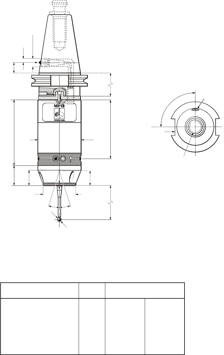
MP18-S
dimensions mm (in)
17.5° 17.5°
21,5
(0.85)
Ø62
(Ø2.24)
Stylus
length
Ø48 (Ø1.89)
95
(3.74)
29
(1.14) 22
(0.87)
85
(3.35)
A
Ø6 (Ø0.24)
B
Ø14,25
(Ø0.56)
7,13
(0.28)
4 (0.16)
Drive slot
90°
To save battery life, the shank switch
must NOT be depressed, during
the time the probe is held in the tool
store.
It may be nesessary to provide a
storage location with a clearance
around the switch.
Thread for pull stud
TAPER SHANK
Complete probe/shank units are
supplied by Renishaw. These
shanks incorporate a switch.
The shank is attached to the
RMP3 using a shank adaptor.
Part No. A-2249-0134.
The method of attachment is
shown on page 15.
BT 40 35 (1.38) 14 (0.55)
BT 50 50 (1.97) 24 (0.94)
ANSI B5.50 - 1985 (CAT) 40 35 (1.38) 14 (0.55)
ANSI B5.50 -1985 (CAT) 50 65 (2.56) 36,8 (1.45)
DIN 69871 40 50,6 (1.99) 14 (0.55)
DIN 69871 50 50,6 (1.99) 36,8 (1.45)
❃ANSI (CAT) MODIFIED 40 35 (1.38) 14 (0.55)
❃ANSI (CAT) MODIFIED 50 65 (2.56) 36,8 (1.45)
Dimensions
ISO
taper A B
Shank type
SHANKS AVAILABLE
❃
These shank specifications are for certain Cincinatti Milacron machines.
Generally to ANSI B5.50 - 1985 (CAT), but with a metric thread for the pull stud.
Orders placed for MP18-S probes require a separate quotation and price.
Please contact Renishaw Custom Products Department.
Taper
shank
RMP3
Shank switch
14
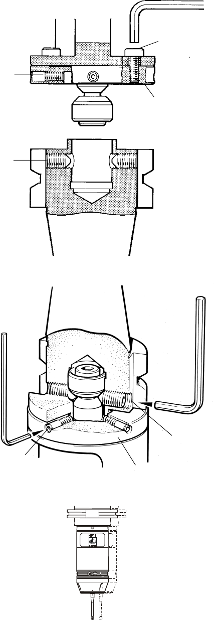
MP18 PROBE/ADAPTOR PLATE/SHANK ASSEMBLY
STYLUS ON-CENTRE ADJUSTMENT
Adaptor plate A-2107-0031
Adaptor plate
Note :
1. DURING ADJUSTMENT CARE SHOULD BE TAKEN NOT
TO ROTATE THE PROBE RELATIVE TO THE SHANK.
2. IF A PROBE/SHANK UNIT IS ACCIDENTALLY DROPPED,
IT SHOULD BE CHECKED FOR ON-CENTRE POSITION.
3. DO NOT HIT OR TAP THE PROBE TO ACHIEVE
ON-CENTRE ADJUSTMENT.
PROBE/SHANK MOUNTING
1. Remove battery covers and battery
- see opposite.
2. Tighten probe/adaptor plate screws A
to 5.1 Nm (3.76 lbf.ft) using special
4mm AF hexagon key (supplied in tool kit).
3. Fully slacken four screws B.
4. Grease two screws C, and fit into shank.
5. Fit probe onto the shank, and visually
position the probe centrally relative to
the shank. Partially tighten screws C
to 2 - 3 Nm (1.47 - 2.2 lbf.ft).
6. Mount the probe/shank assembly into
machine spindle.
2,5mm AF
4mm AF
STYLUS ON-CENTRE ADJUSTMENT
7. Each of the four screws B will move the
probe relative to the shank, in the X or Y
direction as pressure is applied.
Tighten individually, backing off after
each movement.
8. When the stylus tip run-out is less than
20µm, fully tighten screws C to 6 - 8 Nm
(4.4 - 5.9 lbf.ft).
9. For final centering use screws B to move
the probe, progressively slackening on
one side and tightening the opposite screw,
as the final setting is approached, using
two hexagon keys.
Tip run out of 5µm (0.0002 in) should
be achievable.
10. It is important that all four screws B are
tight or tightened to 1,5 - 3,5 Nm
(1.1 - 2.6 lbf.ft) once the final setting
has been achieved.
11. When on-centre adjustment is completed,
replace battery and covers - see opposite.
SHANK
A
B
C
Special short arm
hexagon key 4mm AF
PROBE
SHANK
PROBE
BAdaptor plate
C
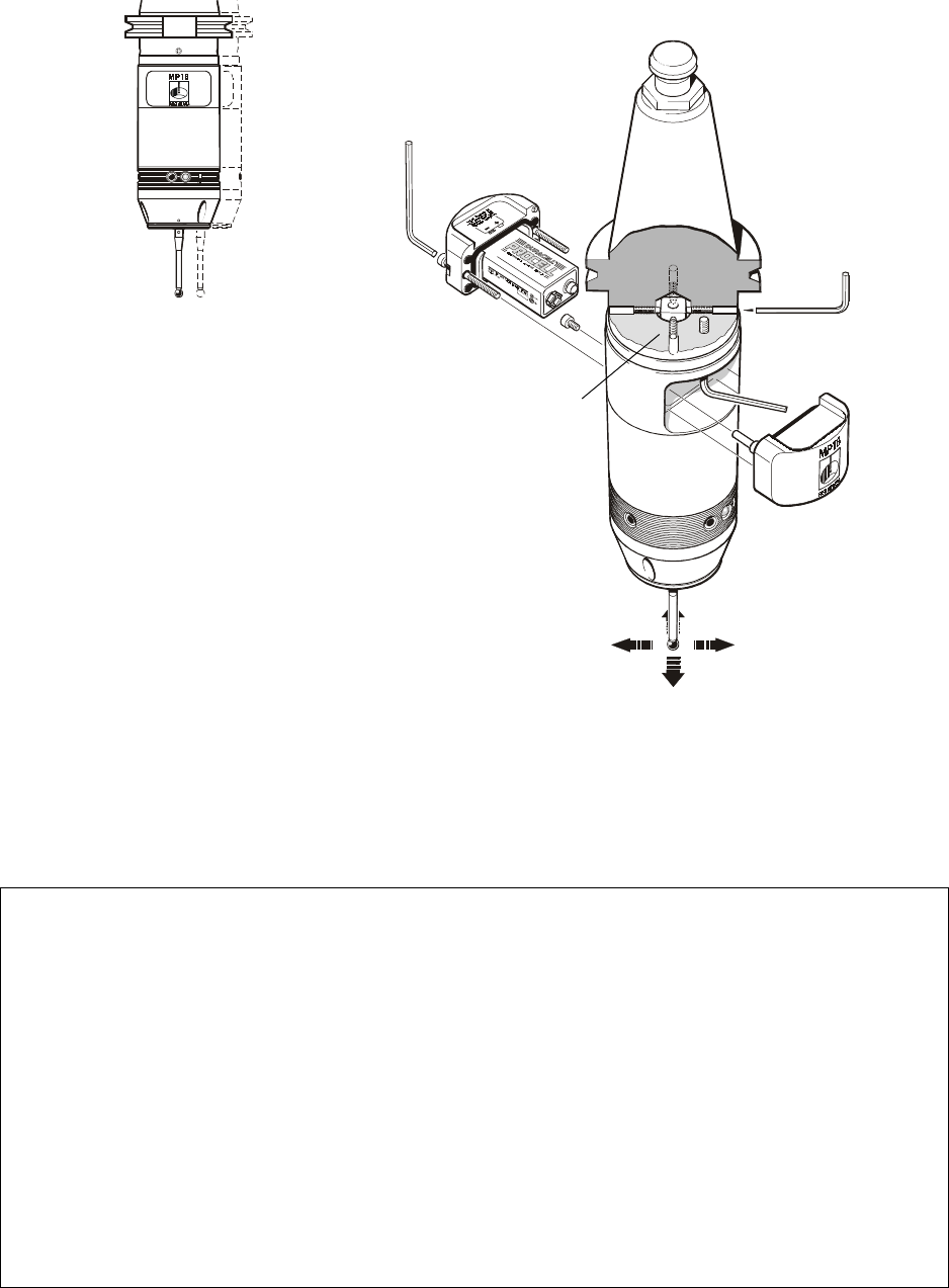
15
A
Four on-centre
adjusting screws
2mm AF
3mm AF
Two clamping
screws
2.5mm AF
Stylus alignment with the spindle
centre line need only be approximate,
except in the following circumstances.
1. When probe vector software is used.
2. When the machine control software
cannot compensate for an offset stylus.
3. The stylus must be parallel to
the spindle axis to prevent stylus stem
contact against the side of deep holes.
MP18-S STYLUS ON-CENTRE ADJUSTMENT
Complete units are supplied on application to
Renishawn Custom Products Department
How to check stylus position
Mount the probe in the machine spindle
and use one of the following procedures.
1. Rotate stylus close to a reference
surface, check if the gap is constant.
2. Rotate stylus against low force dial test
indicator, which does not unseat the probe.
3. Use method advised by machine tool
supplier.
MP18 and MP18-S STYLUS ON-CENTRE ADJUSTMENT
STYLUS ON-CENTRE ADJUSTMENT
1. If adjustment is required, remove
the battery covers and battery.
2. Slacken the two probe/shank
clamping screws half of one turn,
so that the disc washers maintain
a slight clamping grip.
3. There are four adjusting screws A.
Each will move the probe relative
to the shank, in the X or Y direction
as pressure is applied.
Tighten individually. Back off after
each movement.
4. When stylus target position is obtained,
tighten all screws - see page 30.
5. Replace battery and battery covers.
16
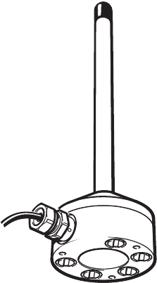
RADIO MODULE MACHINE (RMM2)
Cable side exit and rear exit versions are available
RMM2 RADIO ANTENNA
The RMM2 receives radio signals from the probe,
and passes the signals via a 10m (32ft) coaxial
cable to the MI16 interface.
Two RMM2 units are supplied with each system.
The system can operate with a single RMM,
but there may be areas where the radio signal is
weak. This is a characteristic of all radio systems.
The second RMM2 is positioned to provide good
reception over the probes full working area.
SIGNAL TRANSMISSION ENVELOPE
Radio signals can be transmitted and recieved up
to distance of 15 metres (49ft), in any direction.
Distances greater than this may be achievable
under certain circumstances.
Line of sight between the RMP3 and the RMM2
is not required and the signal can still be received
with the RMP3 fully enclosed in a bore.
Systems operating on the same channel should
be seperated by a distance of 100m (328ft), to
avoid interference with each other.
OPERATING ENVIRONMENT
It is important that the environment is free from
interference at the chosen transmission frequency.
Devices that may make operation difficult include
arc welders, pagers, remote control keys, mobile
phones or another radio probe operating on the
same channel.
An audio monitoring facility is provided to
diagnose causes of interference - see page 18.
RMM2 MOUNTING
Select a flat, metallic surface, ideally away from
corners and bulkheads.
The base of each RMM2 incorporates five
permanent magnets to allow temporary
attachment to a metal surface.
Alternatively three clearance holes are provided
within the base for M4 fixing screws -10mm long
for permanent installation.
RMM2 POSITIONING
Each RMM2 must be installed with care in order
to receive as strong and reliable a signal as
possible from the probe/RMP3 transmission
module.
To guarantee reliability, the MI16 Interface has
two independent reception circuits, each support
one antenna (RMM2). Radio waves are a
coherent form of energy, and reflected signals
may add or subtract to the performance,
resulting in no signal in some positions. To avoid
this, a second RMM2 is recommended.
Commence by connecting a single RMM2 to the
MI16 interface. Position the RMM2 as close as
possible to the working envelope. Activate the
probe/RMP3.
The strength of the radio transmission signal is
observed using the MI16 interface front panel
Rx signal display - see page 18 item 6. Move the
probe around the working envelope and observe
the RX signal display. Identify positions in the
working envelope where the signal is weak or
disappears. A satisfactory signal is indicated by
the RX display signal bars remaining green.
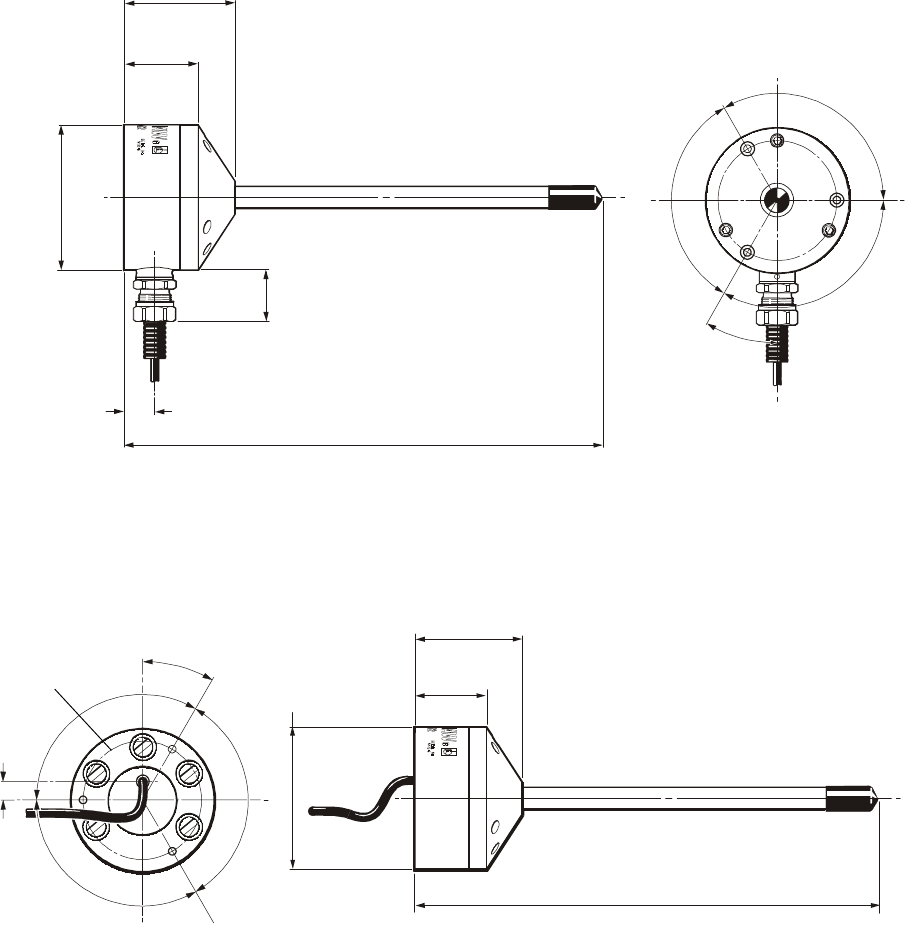
17
60mm (2.36in)
40mm
(1.57in)
Ø82mm
(3.29in)
34mm
(1.39in)
16.5mm (0.65in)
30°
120°
120°
120°
68mm
(2.677in)
PCD
The cable must be protected
from the machine environment
by suitable conduit.
(Thomas and Betts
SHURESEAL 1/4in,
Part No TBEF 0250-50,
or equivalent).
Cable
Conduit
SIDE EXIT CABLE
Disconnect the RMM2 antenna and connect the
second RMM2 cable to either of the MI16
antenna inputs.
Position the second RMM2 such that the regions
of weak signal do not coincide with those
observed with the first RMM2. A good solution is
to mount antennae at 90° to each other.
270mm (10.63in)
Rear view
REAR EXIT CABLE
Top view
60mm (2.36in)
40mm
(1.57in)
270mm (10.63in)
Once a suitable position has been established,
reconnect the first RMM2 and the system is
ready for use.
Ø82mm
(3.29in)
120°
120°
120°
68mm
(2.677in)
PCD
Cable
30°
11,5mm
(0.45in)
dimensions mm (in)
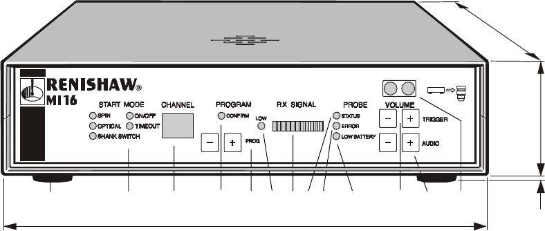
18
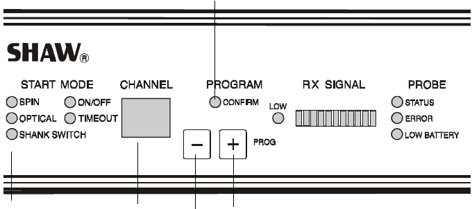
MI16 front panel LED’s display the switch
on/off mode, RMP3 program status, signal
strength, and probe status.
It also provides buttons to select the signal
transmission channel and audio volume.
1START MODE
The selected start mode is indicated
by a lit LED.
2CHANNEL
The display shows the selected
transmission channel.
3PROGRAM CONFIRM
The LED lights to indicate the
successful programming of the RMP3
transmission channel and start mode.
4 PROGRAM BUTTONS
Buttons used to select the required
transmission channel and start
mode for programming of the RMP3.
5LOW Rx SIGNAL LED
Lit when the received signal is too low
(3 or less bargraph segments lit).
6Rx SIGNAL
Indicates the received signal level
(10 segments green for a strong
signal, 0 for probe switched off).
MI16 INTERFACE
dimensions mm (in)
7PROBE STATUS LED
Lit when the probe is seated.
Off when triggered.
8ERROR LED
Lit when an error occurs in the
transmission of the probe signal,
or when the probe is off.
9LOW BATTERY LED
Lit when the battery voltage falls
below 7V. Replace the batteries as
soon as possible after this LED lights up.
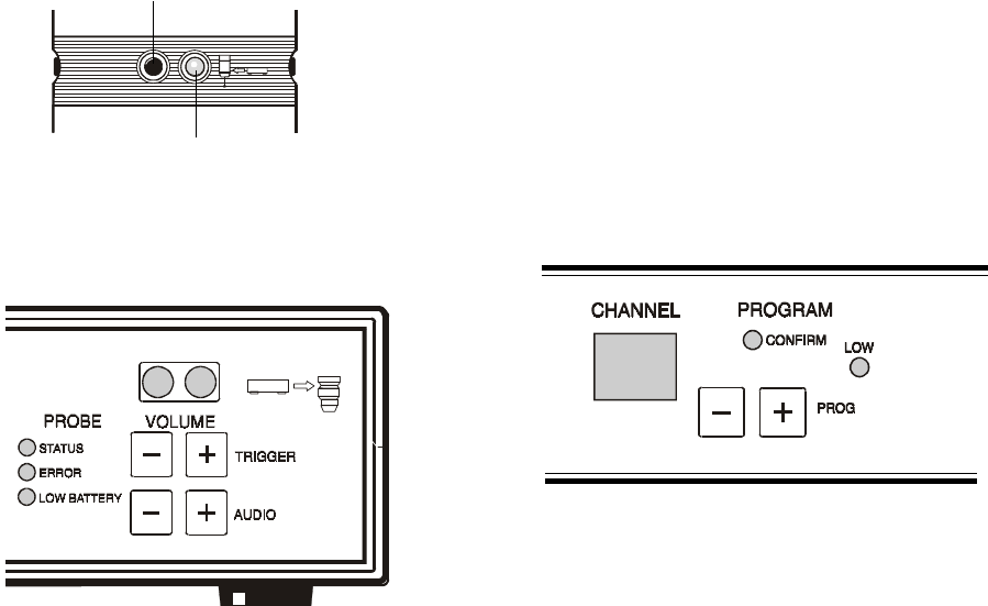
10 AUDIO VOLUME CONTROL
Adjusts the volume of the audible
transmission monitor. Used to diagnose
interference sources.
11 TRIGGER VOLUME CONTROL
Adjusts the volume of the audible
indicator, heard on probe trigger and
to confirm programming operations.
12 PROGRAMMING WINDOW
The LED’s used for RMP3 programming
are mounted behind this window.
To program the RMP3 its programming
LED’s must be aligned with the MI16
programming window.
55mm
(2.16in)
240mm (9.45in)
235mm (9.25in)
5mm
(0.2in)
Self adhesive foot
Ø20mm (0.79in) 1 2 3 4 5 6 7 8 9 10 11 12
The MI16 interface converts probe signals into
an acceptable form for the CNC machine control.
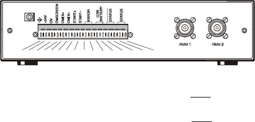
19
1 GROUND
2 +24 VOLTS DC (± 10%)
Capable of supplying 500mA
3 0 VOLTS
4 OM SCREEN
Connection for OM16 cable screen
5 + ve OM16 CONNECTION
6 – ve OM16 CONNECTION
7 + ve MACHINE START
8 - ve MACHINE START
9 ERROR SSR
10 ERROR SSR
11 LOW BATTERY SSR
MI16 REAR PANEL CONNECTIONS
Connections to the CNC machine control, the power supply and RMM2
antennae are located on the MI16 rear panel.
A 16 pin connector is supplied, the pin functions are described below :
12 LOW BATTERY SSR
13 PROBE STATUS SSR
(NORMALLY CLOSED)
14 PROBE STATUS SSR
(NORMALLY CLOSED)
15 PROBE STATUS SSR
(NORMALLY OPEN)
16 PROBE STATUS SSR
(NORMALLY OPEN)
17 BNC CONNECTOR
FOR FIRST ANTENNA
18 BNC CONNECTOR
FOR SECOND ANTENNA
19 CHASSIS GROUND
The MI16 is equipped with an internal power
transformer which ensures that the casing is
isolated from the external power source.
To maintain the isolation the positive (+) and
negative (-) wires must be connected without
contacting the chassis. Use of a shielded cable
is preferred.
INTERFACE GROUNDING
The cable screen must be connected to ground
on the machine controller and to the primary
ground connection on the MI16 Interface connector
(item 1).
The MI16 is equipped with a chassis ground
tab (item 19) which should be used to connect the
MI16 enclosure to the nearest machine ground.
1 2 3 4 5 6 7 8 9 10 11 12 13 14 15 16
19
17 18
20
MI16 AUDIO DIAGNOSTICS
An audio facility, with adjustable volume, is
provided on the MI16 Interface to permit the
identification of interference sources.
In the event of functional disturbances that
suggest radio interference, the audio facility
should be used:
Set the audio volume to maximum, using the
buttons on the front panel of the MI16.
When the RMP3 is active a continuous tone
should be audible, the tone changes when
the probe is triggered.
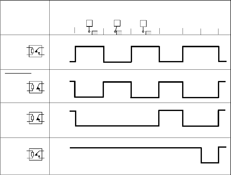
MI16 OUTPUT WAVEFORMS
Probe
reseat
Open
MI 16 OUTPUTS Triggered Seated
PROBE
Seated
Probe
switch
off
Low
battery
Error
low
received
signal (RX)
Probe
trigger
Probe
switch
on
Error
clear
Closed
Normally Open
Closed
Open
Open
Open
Normally
Open
Closed
Normally Closed
PROBE STATUS
ERROR
LOW BATTERY
Closed
Normally Closed
Solid
State Relay Relay
PROBE STATUS
➤
➤
➤
➤
➤
➤
➤
With the RMP3 inactive no tone should be
audible; only background noise.
In either condition the sound should be
observed and any unusual sounds noted.
The frequency of occurrence may then be
correlated to adjacent machinery
(arc welders, paging devices) to identify
the interference source.
If the source of interference cannot be
eliminated, then a change in transmission
channel is recommended.
MI16 PANEL MOUNTING KIT
optional
The MI16 interface panel mounting kit (Renishaw Part No. A-2056-0005) allows the interface to be
mounted in flat panel when a section of the panel is cut out. All MI 16 front features are neatly displayed.
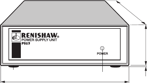
21
The PSU3 supplies power for the MI16 interface when a
24V ±2V dc power supply is not available from the CNC
machine.
The PSU3 is designed for use world-wide.
INPUT
Power to the PSU3 is provided via an IEC mains connector
85 - 264V ac.
47 - 66Hz.
25W maximum.
OUTPUT
24V ±2V dc
0,5 A maximum
The PSU3 is over voltage and over current protected.
Self adhesive foot
Ø12,7mm (0.5in) Green LED
PSU3 POWER SUPPLY UNIT
optional
140mm (5.5in)
3.5mm
(0.14in)
44mm (1.73in)
183mm (7.2in)
dimensions mm (in)
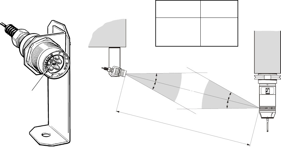
22
OM16 OPTICAL MODULE
optional
OM16 FUNCTION
An M code from the CNC machine control
causes the OM16 to send an optical switch on
or switch off signal to the probe/RMP3.
The appropriate activation mode is selected
and programmed from the MI16 Interface.
The ring of LED’s around the probe body receive
OM16 optical signals in any probe orientation,
provided optical transmitter and receiver LED’s
are mutually in each other view.
OM16 MOUNTING
The module may be mounted directly to the
machine guarding, using the M32 locking nuts
provided on the OM16 body.
OPERATING ENVELOPE
L
Distance L
metres (feet)
OM16
angle A
1 (3.28) ±20°
2 (6.56) ±15°
3 (9.84) ±10°
±A°
Orange LED
Alternatively a mounting bracket is supplied with
the OM16 module. The bracket securing screws
can be loosened to allow the OM16 LED’s to be
directed towards the probe LED’s.
Screws are then re-tightened.
The mounting bracket accepts an M10 size bolt
for attachment to guarding or bulkheads.
OM16 WINDOW
The chosen position for the OM16 should be
selected to avoid direct impact of machining
swarf on the OM16 window. Although the
window is 4mm thick toughened glass, long
term erosion will eventually reduce optical
signal strength.
OM16 LED
An orange LED is lit when a signal is sent.
To assist monitoring system status, the orange
LED must be visible to the operator during use.
The OM16 window and RMP2 LED’s should be wiped clean periodically to remove coolant residues.
Operation outside the temperatures specified for operational use (5°C to 50°C / 41°F to 158°F )
may result in some reduction in transmission range.
The maximum recommended distance between the OM16 and RMP3 is 3 metres.
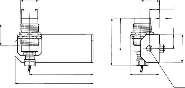
23
OM16 OPTICAL MODULE
dimensions mm (in)
137.5mm (5.41in)
112.5mm (4.43in)
M32x1.5
Ø29mm
(1.14in)
38.3mm (1.51in)
86mm (3.39in)
60mm (2.36in)
51mm (2.01in)
32.5mm (1.28in)
17.5mm (0.69in)
10mm (0.39in)
50mm (1.97in)
25mm
(0.98in)
Ø10.5mm
(0.04in)
WIRING CONNECTIONS
The OM16 is connected to the MI16 Interface with 25 metres
of cable. The cable uses four conductors and the screen.
These should be connected as below:
Cable screen
Connect to ground (MI16 pin 4 - see page 19).
Red and Yellow
Connect both to the +ve OM16 pin on the MI16 Interface
(MI16 pin 5 - see page 19).
Blue and Green
Connect both to the -ve OM16 pin on the MI16 Interface
(MI16 pin 6 - see page 19).
SEALING
The OM16 is sealed to IP68.
A gland suitable for sealing to flexible conduit is supplied as stan-
dard.
The OM16 cable should be protected by flexible conduit.
The recommended type is Thomas and Betts SHURESEAL 1/4in,
Part No. TBEF 0250-50, or equivalent.
24
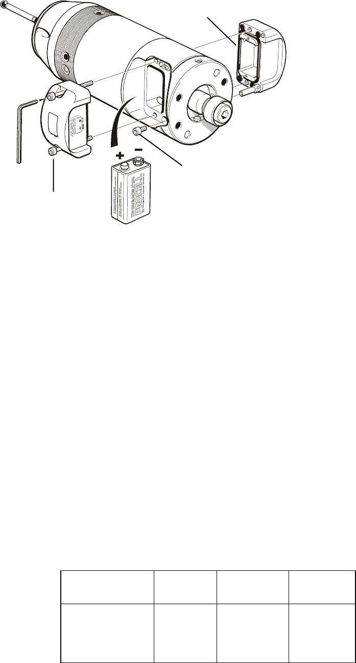
Remove cover to replace exhausted battery
1. Slacken screws (1) and remove battery
cover (2).
2. Remove battery (3).
Do not remove second cover,
to change battery.
Probe/shank mounting and stylus on-centre
adjustment - remove second cover
3. Remove screw (4) and battery cover (5).
To replace battery covers
4. Check that battery cover seals are seated,
and lubricate seals lightly with a mineral
oil or grease.
5. Replace cover (5) - with Renishaw logo.
6. Replace battery with polarity as shown
on label,
7. Replace battery cover (1)
(with battery symbol).
Tighten battery cover screws to
1,1 Nm (0.8 lbf.ft).
Probe battery
Power for the probe is supplied
by one PP3 9V alkaline or lithium
battery. It is essential to select the
type listed in chart, or equivalent.
Low battery warning
When the MI 16 Low Battery
LED lights up, battery voltage
is low and the end of
useable battery life is approaching. (The Low
Battery LED will only light up during the probe
operating mode).
The machine control may also be programmed
to flag up a Low Battery Alarm.
Typical battery reserve life
Using an alkaline battery at 5% usage, the probe
will typically continue to operate for 8 hours, after
the MI 16 Low Battery LED lights up.
Dead battery indication
When the battery voltage drops below the
threshold where performance can be
guaranteed, a probe output relay will also
be forced into its open state, causing the
machine to stop, until a new battery is
inserted. The probe will revert to the
stand-by mode after changing the battery.
TYPICAL BATTERY LIFE EXPECTANCY
BATTERY
(5)
Battery
cover
Battery
cover
(2)
(4)
Screw
2,5mm AF
Cover seal
(3)
Type PP3 9V
battery
(1)
Screw
IMPORTANT
Insert battery as shown
on label
DO NOT leave exhausted
battery in probe
Dispose of exhausted
batteries in accordance
with local regulations
BATTERY
TYPE
Alkaline PP3
MN1604 (Duracell)
Lithium PP3
U9VL-FP
Stand-by
365 days
730 days
5% usage
(72 min/day)
31 days
64 days
Continuous
38 hours
80 hours

25
MODES OF OPERATION
MP18-S PROBE WITH SHANK SWITCH
The MP18-S, is supplied with a modified shank
incorporating a shank switch.
Switch on occurs when the shank is inserted into
the machine spindle causing the switch to
depress and switch the probe on.
The probe switches off when the probe is
TIME OUT PERIOD
This is selectable to 30 sec (± 1sec) or 180 sec
(± 1sec). With prototype RMP3’s or if a Mk1 MI16
is used for programming, then the time out will be
180 sec (± 1sec)
The RMP3 transmission module can be
switched on and off by a number of different
methods:
All options are selectable on the MI16 interface,
and programmed into the RMP3 from the MI16
- see page 26.
When a particular option has been selected,
all other options are disabled.
A standard RMP3 allows any of the options to be
selected except the shank switch method, which
requires a dedicated shank.
removed from the machine spindle.
The shank switch option is selected from the
MI16 machine interface - see page 26.
TAKE CARE
Ensure that the shank switch is not depressed
when the probe is stored in the machine tool
carousel.
MODE
M code
Optical on
Optical off
M code
Optical on
Time out off
Spin on
Spin off
(centrifugal switch)
Spin on
Time out off
SWITCH OFF METHOD
A machine M code causes the OM16
to send an optical signal to the
RMP3, which switches it off.
The RMP3 will switch off once the
timeout period elapses since the last
probe trigger, or since the RMP3 was
last switched on (whichever was
later).
The machine spindle is rotated at 500
rev/min (± 50 rev/min), for a minimum
of 1 sec to ensure reliable switch off.
The RMP3 will switch off once the
timeout period elapses since the last
probe trigger, or since the RMP3 was
last switched on (whichever was
later).
SWITCH ON METHOD
A machine M code causes the OM16
to send an optical signal to the RMP3,
which switches it on.
The machine M code causes the
OM16 to send an optical signal to
the RMP3, which switches it on.
The machine spindle is rotated at
500 rev/min (± 50 rev/min), for a
minimum of 1 sec to ensure reliable
switch on.
The machine spindle is rotated at
500 rev/min (± 50 rev/min), for a
minimum of 1 sec to ensure reliable
switch on.
DEBOUNCE PERIOD
After the probe is switched on it cannot be
switched off again until a period of 2 seconds
has elapsed. Similarly, after switch off, the
probe cannot be switched on again until
2 seconds has elapsed.
MP18 PROBE SWITCH ON / SWITCH OFF OPTIONS
Note for M code probe activation, an OM16 is required.
26
The MI16 Interface and probe/RMP3
transmission module are factory set to
Channel 1. The following procedure
must be followed to set or change the
transmission channel.
The programming of the transmission
channel and the RMP3 activation mode
MODE AND CHANNEL SELECTION
1. The programming mode is entered by
pressing simultaneously the programming
‘+’ and ‘–’ buttons on the front of the MI16
Interface, for approximately 5 seconds.
The Channel Number and Activation Mode
displays will start to flash, to indicate that the
Interface is ready to be programmed.
2. Select the required channel by using the
‘+’ button to increase the channel number,
and the ‘-’ button to reduce the channel
number. 69 channels are available.
3. To change the activation method,
simultaneously press both the ‘+’ and ‘-’
buttons. Each simultaneous press will cause
the activation method to change. The MI16
can be cycled through all the available
activation methods.
is carried out on the MI16 and transferred
to the RMP3 by a short range optical link.
To program the RMP3 it is necessary to bring
the RMP3 close to the front panel of the MI16
Interface. This should be catered for when
selecting the MI16 Interface mounting and
positioning.
4. When a Mk2 MI16 is used, the mode selection
will select 30 sec (± 1sec) time out when the
time out LED is green, or 180 sec (± 1sec)
when the time out LED is red.
5. If neither key is pressed for 5 seconds the
channel number stops flashing, followed by a
double audible beep, and the ‘CONFIRM’ LED
lighting on the MI16 Interface front panel for a
period of 10 seconds. This indicates that
programming of the interface is complete.
If only a change in channel is required, with
no change in activation method, action 5.
may be taken after action 2.
PROGRAMMING THE MI16 INTERFACE
+
–
CHANNEL NUMBER
DISPLAY
CONFIRM LED
ACTIVATION
MODES

27
RADIO FREQUENCY and CHANNEL SEPARATION
1 433.075
2 433.100
3 433.125
4 433.150
5 433.175
6 433.200
7 433.225
8 433.250
9 433.275
10 433.300
11 433.325
12 433.350
13 433.375
14 433.400
15 433.425
16 433.450
17 433.475
18 433.500
19 433.525
20 433.550
21 433.575
22 433.600
23 433.625
Channel
No
Frequency
MHz
Channel
No Frequency
MHz
Channel
No Frequency
MHz
24 433.650
25 433.675
26 433.700
27 433.725
28 433.750
29 433.775
30 433.800
31 433.825
32 433.850
33 433.875
34 433.900
35 433.925
36 433.950
37 433.975
38 434.000
39 434.025
40 434.050
41 434.075
42 434.100
43 434.125
44 434.150
45 434.175
46 434.200
47 434.225
48 434.250
49 434.275
50 434.300
51 434.325
52 434.350
53 434.375
54 434.400
55 434.425
56 434.450
57 434.475
58 434.500
59 434.525
60 434.550
61 434.575
62 434.600
63 434.625
64 434.650
65 434.675
66 434.700
67 434.725
68 434.750
69 434.775
The frequency range is divided into separate channels, each channel
having a typical bandwidth of 25kHz, to permit many systems to operate
in close proximity without the danger of interference.
The operating channel is programmed by push buttons on the MI16.
28
PROGRAMMING THE RMP3 TRANSMISSION MODULE
MI16 INTERFACE
1. To enter the RMP3 programming mode,
remove the probe battery cover and
battery for a period of 10 seconds minimum.
2. Replace the battery cover and battery.
A double green flash from the RMP3
STATUS LED indicates the RMP3 is in
programming mode. The mode is active
for one minute, after which the RMP3
returns to standby status.
3. To program the RMP3 (or check its
current programming configuration) align
the RMP3 programming LED with those
MI16 INTERFACE
RMP3 PROGRAMMING LED
Colour - water clear
on the MI16 front panel. The MI16
programming LED’s are shown below.
4. The MI16 and the RMP3 programming
LED’s must be aligned and held within
100mm (3.93in) of each other for the
optical link to be established.
5. Once the optical link has been established
the interface emits an audible beep every
½ second for 5 seconds and the front panel
displays the current RMP3 configuration.
6. If the RMP3 is now moved away from the
MI16 Interface no programming will take
place. (Useful if the user wishes to verify
the current configuration of the RMP3).
7. If the RMP3 is held in position (see action 4)
a continuous audible beep will be emitted
for 5 seconds, to warn that programming is
about to occur.
If the RMP3 is moved out of range during
this period no programming occurs.
8. At the end of the above period programming
occurs.
9. Successful programming is indicated by a
double audible beep and the ‘CONFIRM’
LED lighting on the MI16 Interface front
panel for 5 seconds.
The RMP3 remains active until the one
minute allowed for programming has
elapsed. At this point the system switches
to standby mode and is ready for use.
10. Incorrect programming is indicated by
continuous audible beeps, flashing of
the channel number display and the
‘CONFIRM’ LED not lighting.
In this event the programming procedure
should be repeated.
LED Colour - black
Programming LED’s.
29
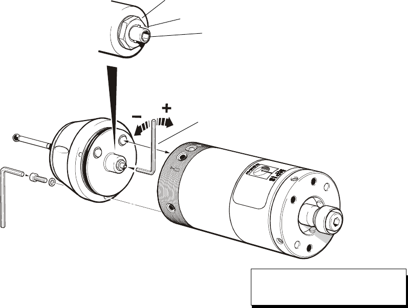
2.5mm AF
Stylus
Locknut 7mm AF
Stop
Adjusting screw
2.0mm AF
Spring pressure within the probe causes the stylus
to sit in one unique position, and return to this position
following each stylus deflection.
Stylus pressure is set by Renishaw.
The user should only adjust spring pressure in special
circumstances e.g. excessive machine vibration or
insufficient pressure to support the stylus weight.
To adjust spring pressure, remove the probe head to
gain access to the spring pressure adjusting screw.
Slacken the locknut, and turn the adjusting screw
anticlockwise to reduce pressure (more sensitive)
or clockwise to increase pressure (less sensitive).
A stop prevents damage, which could be caused
by overtightening the adjusting screw.
Finally tighten the locknut to 1Nm (0.74lbf.ft) and
replace the probe head.
STYLUS SPRING PRESSURE ADJUSTMENT
Gauging force
Align contact pins before
connecting probe head.
DO NOT rotate probe head
when located in radio module
ENSURE THAT THE OMP IS KEPT
CLEAN. DO NOT ALLOW COOLANT
OR PARTICLES TO ENTER THE
PROBE.
STYLUS SPRING PRESSURE
ADJUSTMENT AND USE OF STYLI
OTHER THAN CALIBRATION
STYLUS TYPE, MAY CAUSE
REPEATABILITY TO DIFFER FROM
THE TEST CERTIFICATE RESULTS.
MAINTENANCE
30
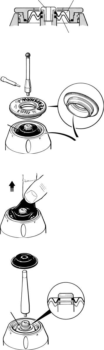
DIAPHRAGM INSPECTION and REPLACEMENT
WARNING:
NEVER ATTEMPT TO REMOVE
DIAPHRAGM WITH METAL OBJECTS
PROBE DIAPHRAGMS
The probe mechanism is protected from coolant
and debris by two diaphragms, these provide
adequate protection under normal working
conditions.
The user should periodically check the outer
diaphragm, for signs of damage and coolant
leakage. If this is evident replace the outer
diaphragm.
The outer diaphragm is resistant to coolant
and oils. However if the outer diaphragm is
damaged, the inner diaphragm could become
weakened with prolonged immersion in certain
coolants and oils.
The user must not remove the inner
diaphragm. If damaged, return the probe
to your supplier for repair.
OUTER DIAPHRAGM INSPECTION
1. Remove the stylus
2. Unscrew the front cover.
3. Inspect outer diaphragm for damage.
4. To remove outer diaphragm, grip near the
middle and pull upwards.
INNER DIAPHRAGM INSPECTION
5. Inspect inner diaphragm for damage.
If damaged return the probe to your
supplier for repair.
DO NOT REMOVE INNER DIAPHRAGM
OUTER DIAPHRAGM REPLACEMENT
6. Screw tool fully into stylus holder.
7. Fit new diaphragm.
8. The diaphragm must locate centrally in
the stylus holder groove.
9. Press diaphragm to expel trapped air.
10. Remove tool.
11. Lightly smear medium grease on front
cover lower surface. Then refit cover
and tighten.
12. Refit stylus
11
Lightly
grease
here
STYLUS HOLDER OUTER DIAPHRAGM
INNER DIAPHRAGM
STYLUS 1 12
STYLUS
TOOL
2
11
3
4
7 9
6 10
8
5
31
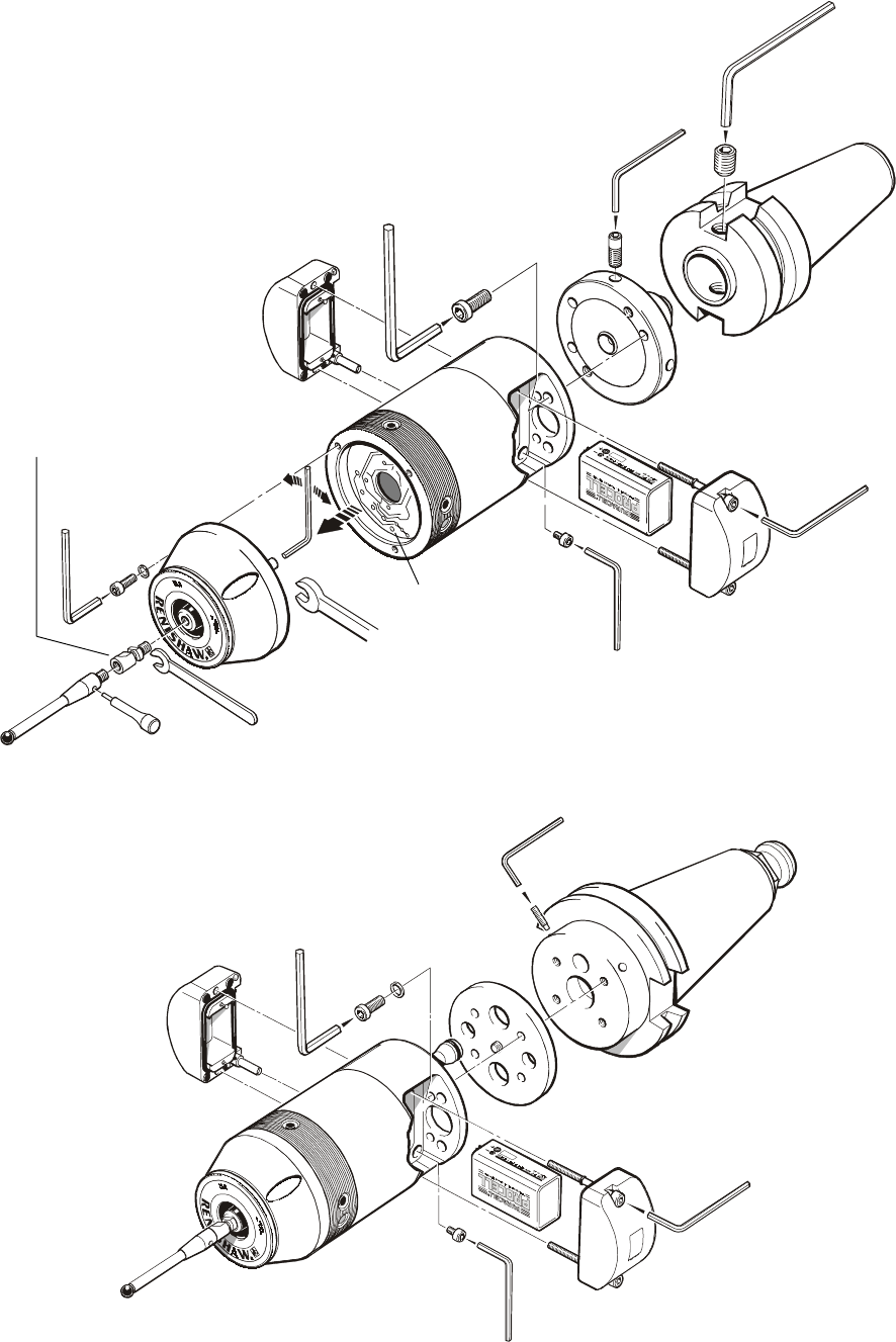
SCREW TORQUE VALUES
4mm AF
6 - 8 Nm
(4.4 - 5.9 lbf.ft)
Shank
MP18 PROBE
MP18-S PROBE
2,5mm AF
6 - 8 Nm
(4.4 - 5.9 lbf.ft)
Special 4mm AF
5,1 Nm
(3.76 lbf.ft)
Adjusting plate
RMP3
Probe head
2,5mm AF
1,1 Nm
(0.8 lbf.ft)
2,5mm AF
1,1 Nm
(0.8 lbf.ft)
7mm AF
1 Nm
(0.74 lbf.ft)
5mm AF
2 Nm
(1.7 lbf.ft)
2 Nm
(1.7 lbf.ft)
Weak link
optional for
steel shaft
styli only 2mm AF
Align RMP3 and
probe head
electrical contacts
2mm AF
1,1 - 3,5 Nm
(1.1 - 2.6 lbf.ft)
3mm AF
2 Nm
(2.21 lbf.ft)
2,5mm AF
1,1 Nm
(0.8 lbf.ft)
2,5mm AF
1,1 Nm
(0.8 lbf.ft)

32
SYSTEM KITS
MP18 KIT ✲ MP18 probe, MI16, RMM2 x two,
shank adaptor, tool kit.
MP18 PROBE ✲ MP18 probe with battery, adaptor plate and
tool kit.
MP18-S PROBE ✲ MP18-S probe with battery, adaptor plate
and tool kit.
MP18-S KIT ✲MP18-S probe, MI16, RMM2 x two,
(ANSI -1985-CAT-SIZE 40) shank adaptor, shank, tool kit.
MP18-S KIT ✲MP18-S probe, MI16, RMM2 x two,
(ANSI -1985-CAT-SIZE 45) shank adaptor, shank, tool kit.
MP18-S KIT ✲MP18-S probe, MI16, RMM2 x two,
(ANSI -1985-CAT-SIZE 50) shank adaptor, shank, tool kit.
MP18-S KIT ✲MP18-S probe, MI16, RMM2 x two,
(ANSI -1978-SIZE 40) shank adaptor, shank, tool kit.
MP18-S KIT ✲MP18-S probe, MI16, RMM2 x two,
(ANSI -1978-SIZE 45) shank adaptor,shank, tool kit.
MP18-S KIT ✲MP18-S probe, MI16, RMM2 x two,
(ANSI -1978-SIZE 50) shank adaptor, shank, tool kit.
MP18-S KIT ✲MP18-S probe, MI16, RMM2 x two,
(DIN 69871-SIZE 40) shank adaptor, shank, tool kit.
MP18-S KIT ✲MP18-S probe, MI16, RMM2 x two,
(DIN 69871-SIZE 45) shank adaptor, shank, tool kit.
MP18-S KIT ✲MP18-S probe, MI16, RMM2 x two,
(DIN 69871-SIZE 50) shank adaptor, shank, tool kit.
MP18-S KIT ✲MP18-S probe, MI16, 2 off RMM2’s,
(BT-1982-SIZE 40) shank adaptor, shank, tool kit.
MP18-S KIT ✲MP18-S probe, MI16, RMM2 x two,
(BT-1982-SIZE 50) shank adaptor, shank, tool kit.
PARTS LIST - Please quote the Part No. when ordering equipment
USER REGION USA
✲ Please contact Renishaw
All MP18-S versions are custom products, requiring a separate quotation and price.
Type Part No. Description

33
SYSTEM
COMPONENTS
RMP3 433 FCC A-2249-0230 RMP3 transmission module with tool kit.
RMP3 S 433 FCC A-2249-0231 RMP3 transmission module and tool kit.
shank switch version (without shank and adaptor plate)
Shank adaptor A-2107-0031 Shank adaptor plate for attachment to MP18 style shanks.
Shank adaptor A-2249-0134 Shank adaptor plate kit for shank switch for attachment
to MP18-S style shanks.
RMM2 side exit A-2137-0170 RMM2 antenna - side exit cable.
RMM2 rear exit A-2137-0470 RMM2 antenna - rear exit cable.
MI16 A-2137-0160 MI16 interface with connector.
OM16 kit A-2137-0401 OM16 optical module and mounting bracket.
Battery P-BT03-0001 Duracell MN1604, PP3, 9V.
Stylus A-5000-3709 PS3-1C stylus, Ø6 ball x 50mm long with ceramic stem.
Weak link kit A-2085-0068 Kit comprising : stylus weak link stem x two, spanner
and instruction sheet.
Weak link stem M-2085-0069 Stylus weak link stem for use with steel shaft styli.
Spanner P-TL09-0003 Spanner for weak link stem.
Styli —See Data Sheet H-1000-3200.
PSU3 power supply —See Data Sheet H-2000-2200
Software —See Data Sheet H-2000-2289.
PARTS LIST - Please quote the Part No. when ordering equipment
Type Part No. Description
USER REGION USA
34
ADDENDUM 1
Radio system component compatibility
Complete MP14 and MP16 probe systems may be exchanged with
complete MP18 and MP18-S probe systems.
Component compatibility
NOT ALL MP18 components are compatible with components used
with the earlier MP14 radio transmission system.
Components with identical model name/number are interchangeable
between systems.
Earlier MP14 systems incorporating an RMP, RMM and the MI14 interface
DO NOT function with current systems using the RMP2
(used with MP16), RMP3 (used with MP18), RMM2, MI16 interface
and the OM16 optical module.
Probe/RMP2/RMP3
The RMP2 and RMP3 will communicate with the RMM and RMM2,
provided they are set to operate on the same channel.
The MP18 probe is smaller and lighter than the MP14 and MP16 probes.
RMM and RMM2 antenna
Both antenna use the same base. The RMM2 antenna is shorter than
the RMM antenna.
Interface unit
The MI14 interface has been replaced by the MI16 interface, both
units are the same size. All electrical outputs and inputs to the MI16 Interface
remain unchanged from the MI14 Interface.
(Note that a 16 pin plug is required for connection to the MI16 Interface rather
than the 14 pin connector used on the MI14 Interface. The two extra contacts
allow connection to the OM16 Optical Module).
35
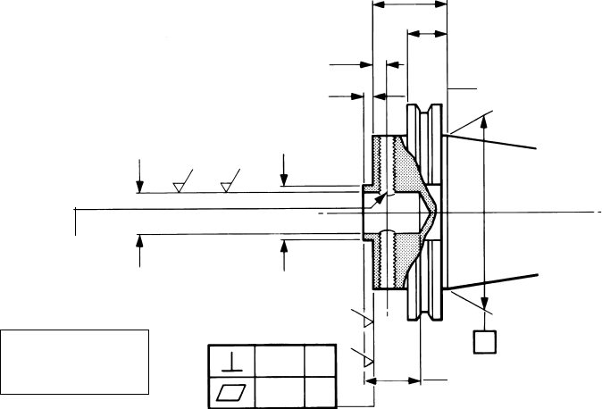
ADDENDUM 2
Shank manufacturing details for MP18
❃
Shank manufacturing details to prepare shank for MP18 shank adaptor
(shank without shank switch)
GAUGE LINE
A
B
❃6 (0.24)
C
Ø20,10 (0.791)
Ø20,02 (0.788)
Two holes
M8 x 1,25 Thro.
equi-spaced
into bore
For reference only 27,5 (1.08)
25,5 (1.00)
0.8 (32)
❃
❃
0.8 (32)
❃
Not convex
❃4,5 (0.18)
4,3 (0.17)
Ø25,0 (0.984)
Ø24,8 (0.976)
0,05
C
0,02
Dimensions
A and B
are shown on
page 12
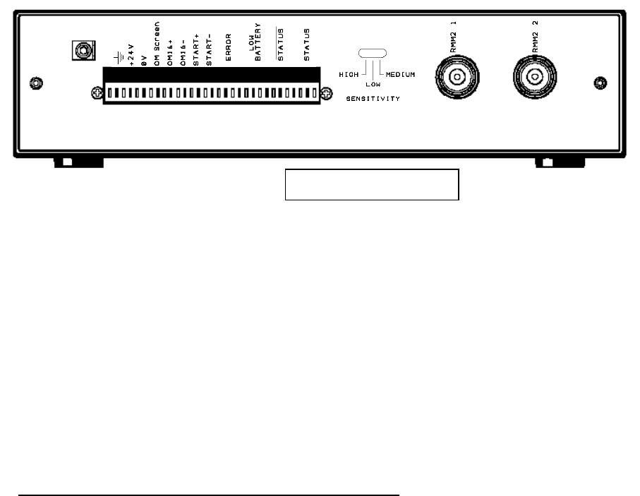
ADDENDUM 3
SELECTION OF MI16 SENSITIVITY
The MI16 MK3 version has an integral switch which allows the selection of the radio
reception sensitivity level.
The switch is located on the rear panel.
Switch : 3 positions
The sensitivity can be selected from three levels:
HIGH : The reception sensitivity is strong.
ðThe reception distance is longer.
ðThe parasitic sensitivity is increased.
LOW : The reception sensitivity is lower.
ðThe reception distance is smaller.
ðThe parasitic sensitivity is diminished.
MEDIUM : This position is a compromise between the two previous.
ADVICE ON SELECTION OF SWITCH POSITION
The choice of the switch position is dependent on the probe power version sold in the
different markets.
The following positions are recommended:
HIGH = USA Market
LOW = CEE Market
MEDIUM = JAPAN Market
Note : The choice of the MI16 interface sensitivity does not replace the procedures for
the antenna installation (see RMM2 ANTENNA-Operating envelope and installation).
36

Renishaw reserves the right to change specifications without notice.
Renishaw plc, New Mills, Wotton-under-Edge, Gloucestershire, GL12 8JR, United Kingdom.
International Tel +44 1453 524 524 National Tel 01453 524 524 [07000 RENISHAW]
International Fax +44 1453 524 901 National Fax 01453 524 901
Telex 437120 RENMET G email genenq@renishaw.com
GROUP COMPANIES
Renishaw Latino
Americana Ltda.,
Calçada dos Crisântemos 22,
C.C. Alphaville,
C.e.p. 06453-000, Barueri SP,
Brazil.
Tel +55 11 7295 2866
Fax +55 11 7295 1641
email brazil@renishaw.com
Renishaw (Hong Kong) Ltd.,
Unit 4A, 3/F, New Bright Building,
11 Sheung Yuet Road,
Kowloon Bay,
Hong Kong.
The People’s Republic of China.
Tel +852 2753 0638
Fax +852 2756 8786
email hongkong@renishaw.com
Renishaw S.A.,
15 rue Albert Einstein,
Champs sur Marne,
77437 Marne la Vallée,
Cedex 2,
France.
Tel +33 1 64 61 84 84
Fax +33 1 64 61 65 26
email france@renishaw.com
Renishaw GmbH,
Karl-Benz Strasse 12,
72124 Pliezhausen,
Germany.
Tel +49 7127 9810
Fax +49 7127 88237
email
germany@renishaw.com
Renishaw S.p.A.,
Via dei Prati 5,
10044 Pianezza,
Torino,
Italy.
Tel +39 011 9 66 10 52
Fax +39 011 9 66 40 83
email italy@renishaw.com
Renishaw KK,
Across City Nakano-Sakaue,
38-1, Chuo 1-chome,
Nakano-ku,
Tokyo 164-0011,
Japan.
Tel+81 3 5332 6021
Fax +81 3 5332 6025
email japan@renishaw.com
Renishaw Iberica S.A.,
Edificio Océano,
Calle Garrotxa 10-12,
Parque Más Blau,
08820 Prat de LLobregat,
Barcelona,
Spain.
Tel +34 93 478 21 31
Fax +34 93 478 16 08
email spain@renishaw.com
Renishaw A.G.,
Poststrasse 5,
CH 8808 Pfäffikon,
Switzerland.
Tel +41 55 410 66 66
Fax +41 55 410 66 69
email switzerland@renishaw.com
Renishaw Inc.,
5277 Trillium Blvd,
Hoffman Estates, Illinois 60192,
U.S.A.
Tel +1 847 843 3666
Fax +1 847 843 1744
email usa@renishaw.com
REPRESENTATIVE OFFICES
Australia Tel +61 3 9553 8267
Melbourne Fax +61 3 9592 6738
email australia@renishaw.com
The People’s Republic of China
Beijing Tel +86 10 6410 7993
Fax +86 10 6410 7992
email china@renishaw.com
Indonesia Tel +62 21 428 70153
Jakarta Fax +62 21 424 3934
email indonesia@renishaw.com
Singapore Tel +65 897 5466
Fax +65 897 5467
email singapore@renishaw.com
REPRESENTATIVE OFFICES
Taiwan Tel +886 4 251 3665
Taichung city Fax +886 4 251 3621
email taiwan@renishaw.com
India Tel +91 80 509 5419
Bangalore Fax +91 80 509 5421
email india@renishaw.com
LIAISON OFFICE
South Korea Tel +82 2 565 6878
Seoul Fax +82 2 565 6879
email southkorea@renishaw.com
www.renishaw.com
© Renishaw 2000 Issue date 09.00