Rentokil Initial 1927 plc GSD-500349 LongReach Radio Module User Manual Connect Radar
Rentokil Initial 1927 plc LongReach Radio Module Users Manual Connect Radar
Contents
- 1. Users Manual - Control Panel
- 2. Users Manual - AutoGate Connect
- 3. Users Manual - Connect Radar
- 4. Users Manual - MMT
- 5. User Manual
- 6. User manual
Users Manual - Connect Radar
Connect
Radar
Instruction Manual
This manual is based on the latest information and is provided subject to alteration.
We reserve the right to change the construction and/or configuration of the product at any time
without obligation and to modify earlier versions of the product.
Instruction Manual Connect Radar 2017 Version 1.1 GSD-100549
Relates to :
Connect Radar – 304776
This product has LongReach Technology Inside
Instruction Manual Connect Radar 2017 Version 1.1 (GSD-100549)
Page 2
No part of this document may be reproduced, republished or retransmitted in any form or by any
means, whether electronically or mechanically, including, but not limited to, by way of photocopying,
faxing or recording without the express written permission. We reserve the right to revise this
document without the obligation to notify any person and/or entity. All other company or product
names mentioned are used for identification purposes only and may be trademarks of their respective
owners.
LIMITATION OF LIABILITY AND DAMAGES
The product and the softwares within are provided on an “as is” basis. The manufacturer and
manufacturer’s resellers (collectively known as “The Sellers”) disclaim all warranties, express, implied
or statutory, including and without limitation the implied warranties of non-infringement,
merchantability or fitness for a particular purpose, or any warranties arising from course of dealing,
course of performance, or usage of trade. In no event will the sellers be liable for damages or loss,
including but not limited to direct, indirect, special, wilful, punitive, incidental, exemplary or
consequential damages, damages for loss of business profits, or damages for loss of business of any
customer or third party arising out of the use or the inability to use the product, including but not
limited to those resulting from defects in the product or documentation. In no event shall the sellers’
total cumulative liability of each and every kind in relation to the product exceed the cost to replace
the product.
Product disposal instructions
for residential users
The Waste of Electrical and Electronic Equipment (WEEE) Directive (2002/96/EC) has
been put in place to recycle products using best available recovery and recycling
techniques to minimise the impact on the environment, treat any hazardous
substances and avoid increasing landfill. The symbol shown above and on the product
means that the product is classed as Electrical or Electronic Equipment and you should
not put it into your domestic waste bin. When you’ve no more use for it, please
dispose of the product according to your local authority’s recycling scheme. For more
information, please contact your local authority or the retailer
where you bought the product.
NOTICES
Instruction Manual Connect Radar 2017 Version 1.1 (GSD-100549)
Page 3
Safety Instructions
•Only use the Battery Pack Part Number 180338 that is supplied by
Rentokil. This battery pack is not rechargeable and should never be
recharged.
•If the Radar is to be stored for a long period of time then the battery
pack should be removed from the device.
•This appliance can be used by children aged from 8 years and above
and persons with reduced physical, sensory or mental capabilities or
lack of experience and knowledge if they have been given
supervision or instruction concerning use of the appliance in a safe
way and understand the hazards involved.
•Children should be supervised to ensure that they do not play with
the appliance.
•Do not use the device if it is damaged.
•Do not expose the device to corrosive liquids.
•Do not use this device near to water sources.
•This device contains Radio Emitting devices and should not be used
near to life support systems.
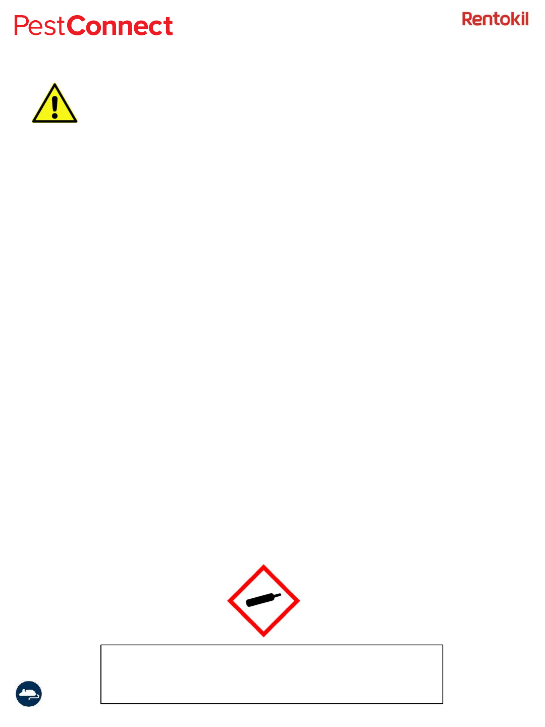
•This device contains a pressurised Carbon Dioxide (CO2) canister and
should not be heated or incinerated. The hazard pictogram below
shall be attached to the product.
Note: If the equipment is used in a manner not specified
by the manufacturer then the protection provided by
the equipment may be impaired.
Instruction Manual Connect Radar 2017 Version 1.1 (GSD-100549)
Page 4
Pest Connect Overview
Pest Connect is a system that enables remote monitoring of devices. Data from sensors are sent
to a Connect Control Panel. The Connect Control Panel establishes a secure connection to a
central server where the data is entered into a database.
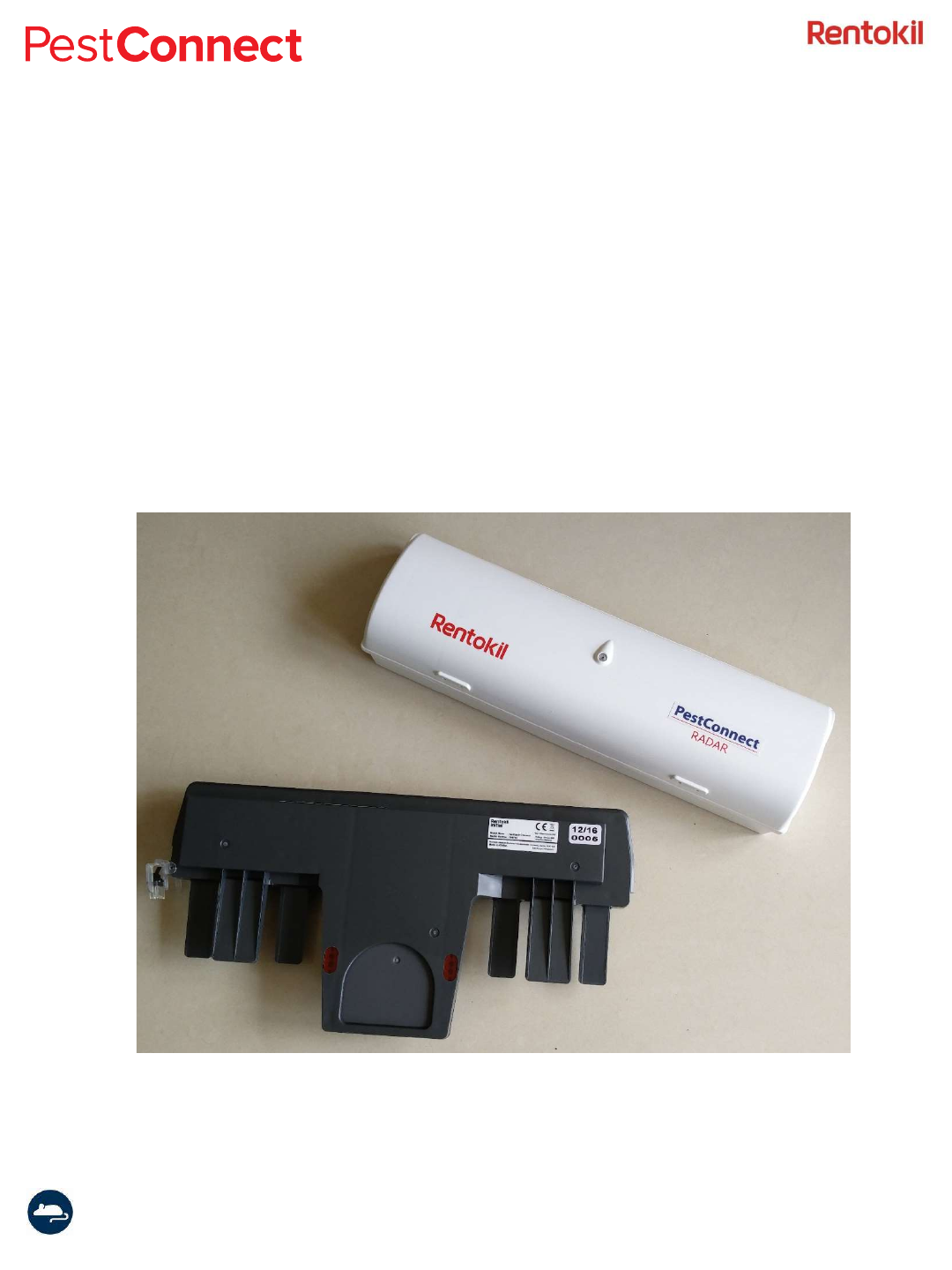
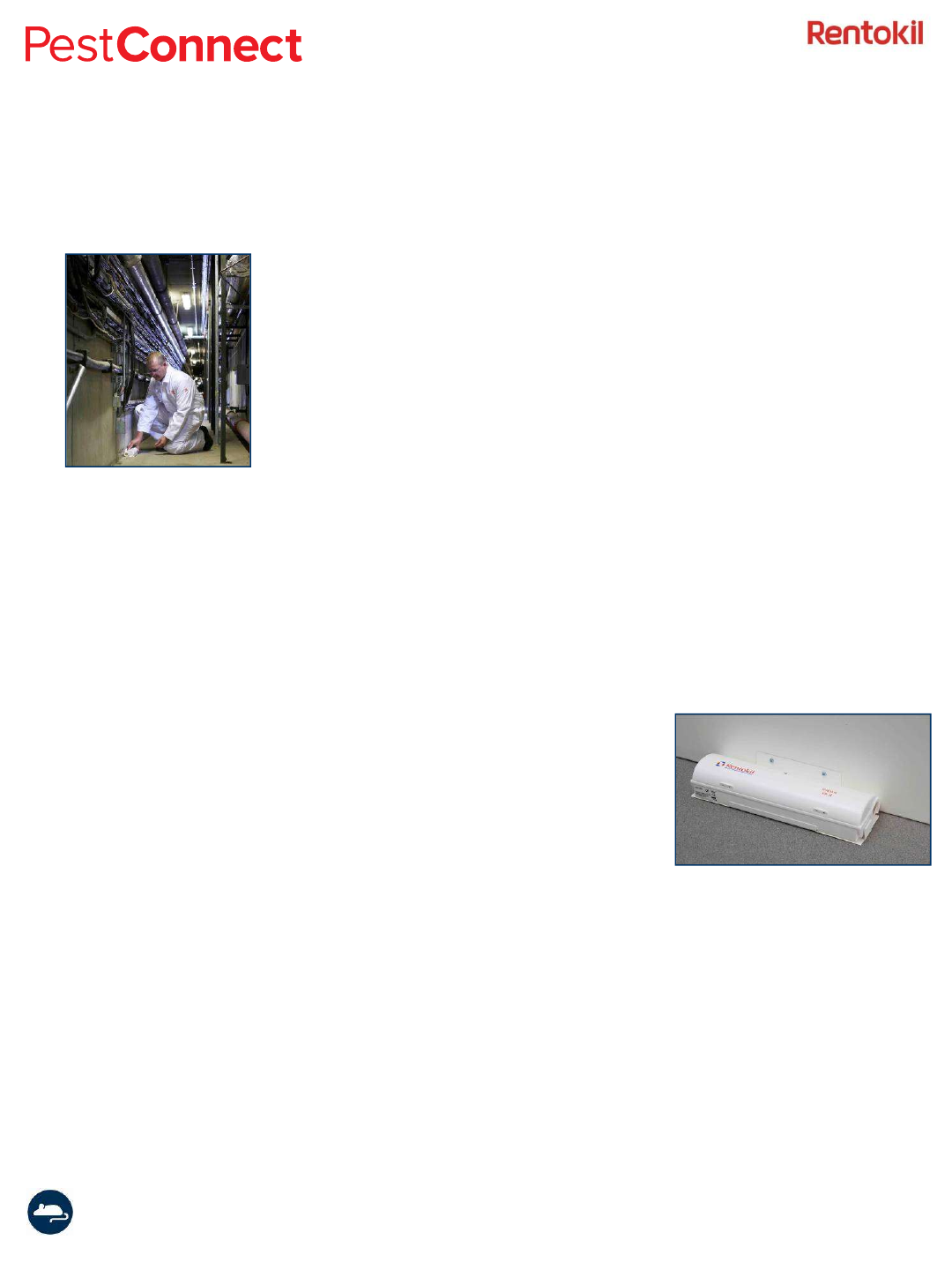
Typical sensors that are used in the Pest Connect system are the Radar Connect mouse trap and
the AutoGate Connect, shown below in Figure 1.
A typical installation will have many sensors communicating to the Connect Control Panel. A
single Control Panel can manage up to 300 sensors and where necessary multiple Control Panels
could be deployed onto a site. In such a system if the sensors fail to connect to the Control Panel
they will scan for alternative Control Panels to ensure high levels of connectivity.
Figure 1: Connect System Overview
Radar Connect
AutoGate Connect
Instruction Manual Connect Radar 2017 Version 1.1 (GSD-100549)
Page 5
Product Description
Radar is a stand alone, battery powered unit that has been designed to
capture, kill and contain mice efficiently, hygienically and humanely. It is
designed primarily for high risk customers, such as food processing
plants, pharmaceutical manufacturing and computer suites, where there
is zero pest tolerance or conventional baiting is not allowed. However,
the many product features of Radar make it suitable for a wide range of
customers as it can operate in a variety of environments. Intruding mice
are captured as soon as they are detected, immediately reducing the risk
to the customer. They are then killed by concentrated release of carbon
dioxide (CO2) into the air tight unit. CO2is capable of killing mice
extremely rapidly and is widely recognised as a humane method of
control. The mouse is unconscious within 15-20 seconds and fatal levels
are reached within 45 seconds of the unit’s activation. Currently, under
existing legislation, CO2is approved for use as a rodenticide or exempt
from registration in many countries. CO2is being fully supported by
Rentokil for this use under the European Biocidal Products Directive.
Radar has been designed by Rentokil to exploit the travelling habits
of mice as opposed to more traditional methods which target their
feeding behaviours, e.g. baiting. Correctly installed units will typically
be placed at wall / floor junctions, relying on a mouse’s natural
curiosity and tendency to run against walls. Radar has two entrances,
one at each end of the unit, to allow mice to run along its
passageway. Two Infrared emitters are continuously pulsing light,
which is reflected off the mouse’s fur, bouncing back to the Infrared
detectors. This activates a circuit that immediately closes both
entrances, trapping the mouse inside a tightly sealed chamber.
Simultaneously, a pressurised canister is locked open to fill the unit
with carbon dioxide. The customer is provided with 24/7 pest control
and can be reassured that the product is both effective and humane,
reducing the risk to their stock and premises.
Radar signals the capture of a mouse sending a message to the Connect Control Panel and then
Server. A technician will receive an alert and arrive promptly to empty, clean, service and reset
the unit. Rigorous testing and quality controls have been implemented at every stage of the
manufacturing process to ensure that Radar is a high quality product that is capable of
supporting a high quality service proposition.

Instruction Manual Connect Radar 2017 Version 1.1 (GSD-100549)
Page 6
Product Functions
The LongReach radio system ensures reliable connectivity over large distances to the
control panels. Beacon signals are emitted from the Control Panels and so the Radar
will connect to the Control Panel with the best connection but in an system with
multiple Control Panels it will select an alternative if the connection to the initial one
fails.
It is important to recognise that in a linear chain of repeaters the system is only as
good as the weakest link. One badly positioned Repeater can cause the loss of
connection of all Sensors and Repeaters beyond it, so it is important to take time to be
happy with the locations you have chosen. In general terms, Square sites tend to
naturally provide multiple routes, whereas long, thin sites will require more care to
ensure that there are no weak points in the system.
The loss of connection to the radio system will cause Sensors to retry the connection
and attempt to make a new one if it can. If connection continues to be unsuccessful
the software automatically increases the time between attempts to conserve battery
life. For normal usage the power consumption of the detector units is comparable to
the standard Radar and MMU products – therefore the recommendation is to replace
all PestConnect installation detector batteries at 12 monthly intervals (all at the same
time) to maximise the installed system performance.
There are some system limitations that should be kept in mind, although typically
should only occur in very large systems:
The maximum number of units that can be connected to a Control Panel is 300 and so
if more devices are required then an additional control panel will be required.
Instruction Manual Connect Radar 2017 Version 1.1 (GSD-100549)
Page 7
Installation
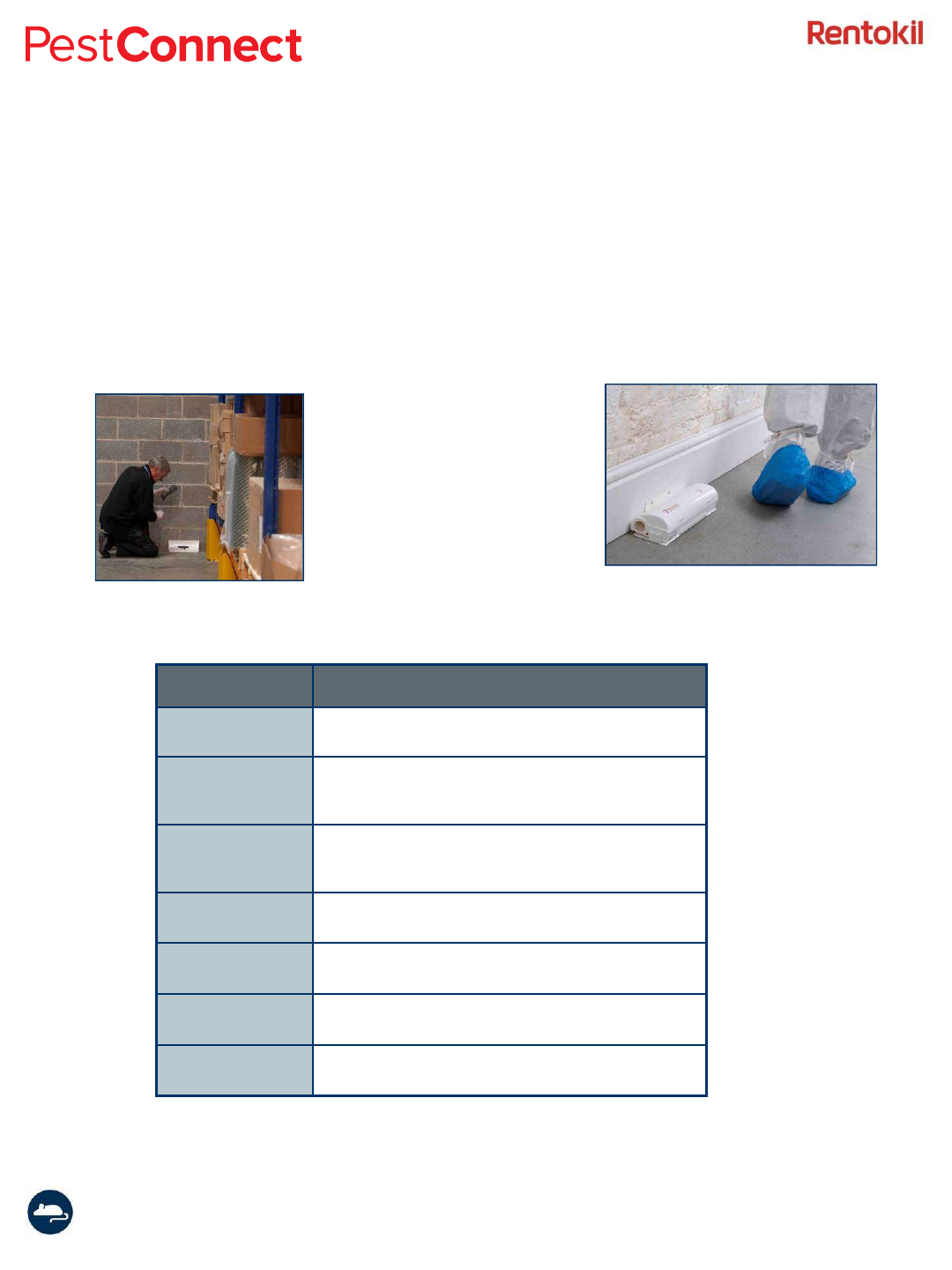
Radar units should be sited along wall / floor junctions, behind machinery and equipment,
i.e. anywhere that bait boxes and mouse monitor units (MMU’s) would normally be
placed. Units should be secured with fixing brackets if possible to prevent the unit being
accidentally moved, knocked or removed by unauthorised persons. The unit ideally should
be sited where the LED is clearly visible to signal an activation.
Environmental
Restrictions Details
Outdoor use Radar has been specifically designed for indoor applications
only. The product is not suitable for outdoor use.
High levels of surface
water
The system electronics can be damaged by water. Take
care to locate units away from areas where local high
pressure washing or hosing down operations are carried
out.
High levels of dust /
grease
It is important that units are kept clean, especially if installed
in areas where high levels of dust or grease are present.
Cleaning guidelines must be followed to prevent damage to
the units.
Knocking / kicking
Care must be taken to locate units away from pedestrian
traffic to avoid false activation. This can be prevented by
mounting units on fixing brackets.
Extreme temperature
(<0°C)
Extremely low temperatures (i.e. unheated warehouses)
could affect Radar’s performance and may result in the unit
entering low battery status mode.
High humidity (> 80%)
or condensation
High humidity and / or condensation could result in damage
to the unit’s control electronics and result in false
activations.
High levels of
vibration
High vibration due to localised machinery / fridge
compressors etc could affect the performance of the unit
and result in false activations.
Instruction Manual Connect Radar 2017 Version 1.1 (GSD-100549)
Page 8
Setup
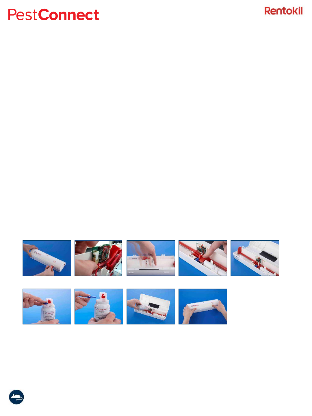
Open the Radar unit using the supplied key. (Figure 1)
The unit is supplied with the battery fitted.
Slide circuit board switch to ‘ON’ – the LED will be red. (Figure 2)
Pass your finger across the first beam and the LED will flicker repeatedly. (Figure 3)
Move your finger to the second beam within four seconds – the solenoid will self test to complete
check and the unit doors will close.
If the Control Panel is operating and in range of the Radar then the LED will flash purple to indicate
that the beacon signal is being received. After a short period* the LED will flash blue to indicate
that it has successfully joined the network. If however there is no beacon signal within range then
the LED will flash red at this point you should check that the Control Panel is powered otherwise
an additional Control Panel could be required on the site.
Once the Radar has joined the network, set the trigger by pressing the red door level down until it
is locked under the blue catch. (Figure 4 & 5)
Remove the blue safety pin from the CO2canister and ensure the canister is within its expiry date
before installing into the unit. (Figure 6 & 7)
Locate the canister in position – it should not need forcing. (Figure 8)
Close the unit securely. (Figure 9)
Note: If the canister resists the fittings, it is likely to be used and in need of disposal
* The time taken to join the network will depend on which radio scheme is being used i.e. which country the units are
deployed. In the European regions the join time should be less than 30 seconds but in North American and some
Asian regions where frequency hopping protocol is used it could take a few minutes to join the network.
Figure 1 Figure 2 Figure 3 Figure 4 Figure 5
Figure 6 Figure 7 Figure 8 Figure 9
Instruction Manual Connect Radar 2017 Version 1.1 (GSD-100549)
Page 9
Radio Check Mode
Setup (cont.)
The LongReach enabled Control Panel should be powered before starting to install the sensors.
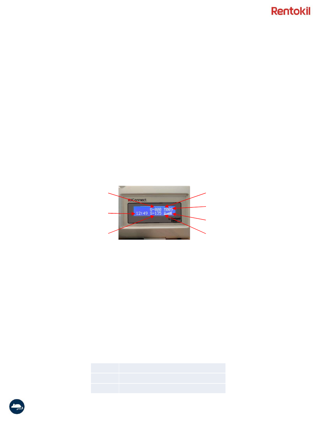
Ensure that the LongReach network has started up by checking that the Network Symbol (shown
below) is no longer flashing on the display.
As each device joins the network the Number of Connected Devices shown will increment. Note:
if the device is switched off it will remain in the device count for 3 hours or until the Control Panel
is reset.
It should be noted that messages are only sent every 15 minutes from a Radar device and so it
could take up to this time for the messages to appear on the queue on the Control Panel. As the
communication is encrypted the negotiation of the session can also take 15 minutes meaning that
the initial message will take up to 30 minutes.
It is possible to put the Radar into Radio Check mode where the signal strength is indicated by the
colour of the flashing LED.
To put the Radar into Radio Check Mode, switch on the Radar and wait for 10 seconds. The LED
will be solid red for the first 10 seconds and then change to orange when Radio Check can start.
Break the infrared beams (in the same way as the normal setup) to start the Radio Check.
The LED will now flash each 2.7 seconds to indicate the state of the connection to the Control
Panel with the following values:
Network Symbol
Number of Connected Devices
Signal Strength
Cellular Symbol
UTC Time
Number of Queued Messages
Number of Sent Messages
Blue Good Signal level
Yellow Functional but should be improved
Red No Signal
Instruction Manual Connect Radar 2017 Version 1.1 (GSD-100549)
Page 10
Connect Status
Switch ON
Technician Test
System Sensing
iR Sensor
Blocked
iR Triggered
Remotely
Triggered
Sensor Blocked
Battery level <5.3V
Mouse
Detected
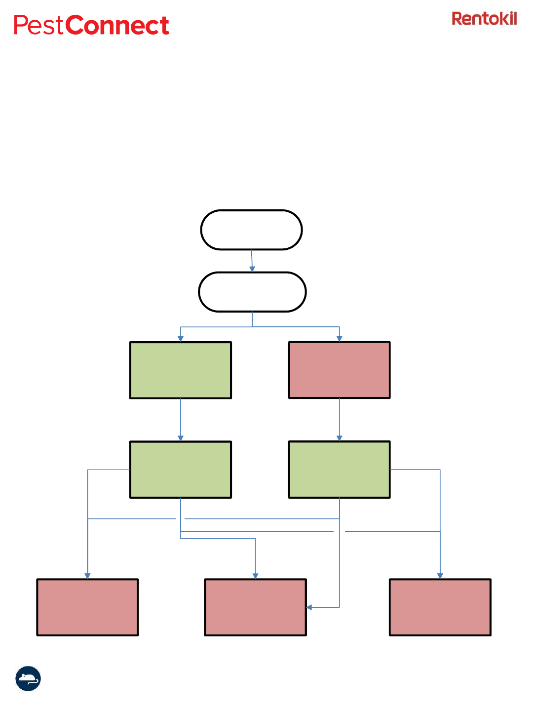
Below are the status messages that can be sent to the Rentokil Data Portals.
When the Radar has been set it will report the status of “System Sensing” to the
servers. If a mouse is detected then the Radar will trigger and report “iR
Triggered” to the servers.
Technician
Test
Technician Test
Failed
System Sensing
after tech test
fail
Instruction Manual Connect Radar 2017 Version 1.1 (GSD-100549)
Page 11
Cleaning / Maintenance
Radar requires no maintenance other than cleaning and management
of the batteries and CO2canisters.
The recommended cleaning product for Radar is the Universal Hard
Surface Wipes (PSU01). These wipes are readily available from Rentokil
Initial Supplies.
Ensure that you wear protective gloves during the cleaning of the unit.
Remove the dead mouse and dispose of it in accordance to standard
protocol. Remove any external dirt, paying particular attention to any
accumulated dirt on the underside of the unit.
Clean the inside of the unit, cleaning any fur, urine, droppings, etc.
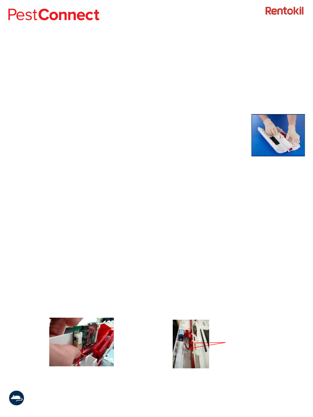
Battery Change
Alkaline batteries should be disposed of in accordance with local, national or state
regulations, or recycled where such facilities exist. It is recommended that battery packs
are replaced every 12 months, irrespective of use, to ensure that they are fit for purpose.
Exhausted batteries are to be removed from the Radar and disposed of as above.
To replace the battery remove the label which holds it in place, remove the connector
from the electronics board and remove the battery.
Remove the battery connector Hook the cable under the clips
Retaining Clips
Instruction Manual Connect Radar 2017 Version 1.1 (GSD-100549)
Page 12
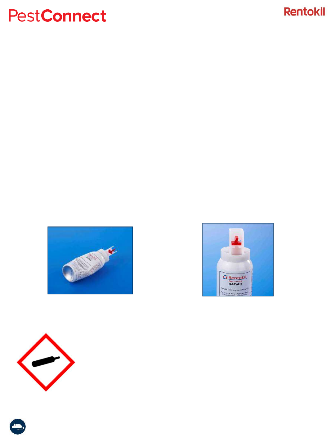
Changing CO2 Canister
A new canister will need to be inserted every time the Radar unit is activated (please ensure a new
canister is within the expiry date). After firing, the red wedge at the neck of the CO2canister it is
held inside by a ratchet that empties it completely. This ensures that empty canisters cannot be
reused by mistake. Empty canisters are not classified as hazardous waste and can therefore be
disposed of in accordance with local, national or state regulations, or recycled where such facilities
exist. However, full canisters are classified as “Hazardous Pesticide Waste” and therefore MUST be
discharged prior to disposal. The canisters should be discharged by holding the canister horizontally
away from the body and pushing the trigger, thus dispensing the contents. It is recommended that
CO2canisters are replaced every 12 months, irrespective of use, to ensure that they are fit for
purpose.
Canisters that have been emptied should be marked as used by pressing a dent into the can as
shown below.
Note: This product contains a pressurised Carbon
Dioxide (CO2) canister. I shall not be heated or
incinerated.
Instruction Manual Connect Radar 2017 Version 1.1 (GSD-100549)
Page 13
LED patterns
LED Meaning Notes
Static Red · Occurs after first turning on the device
· Waiting for the sensors to be tested
· Once technician test is complete sensor will start
in normal mode.
· Times out after 10seconds
Static Yellow · Occurs after 10seconds in Static Red
· Waiting for sensors to be tested, pass hand in
front of the sensors
· Once technician test is complete sensor will start
in radio test mode.
· Times out after 20seconds (will power down at this
point)
Rapid flashing Red Sensing first sensor in technician
test mode
· Occurs when one sensor is obstructed in
Technician test mode (obscuring second sensor
triggers trap)
Flashing Purple Beacon signal found, waiting for
a join request
· Unit is scanning to find PestConnect Control
Panels and comparing signal strengths to select
the best route
Flashing Red No beacon signals found · Check that the control panel is plugged in and
sending beacons
Flashing Blue (2 second
interval)
Test Mode: within radio range · Good radio signal
Flashing Yellow (2
second interval)
Test Mode: low radio signal
<120dB
· Weak signal being received - consider moving the
control panel or installing an additional one.
Flashing Red (2 second
interval)
Test Mode: not in radio range · No beacon signal being received
· Occurs either after scanning or after test mode
· Indicates it is about to arm, and has connection
through to a Control Panel
· Occurs either after scanning or after test mode.
· Indicates it has been unable to make a connection.
It will retry automatically
3 even Red flashes Unable to make final connection
to Control Panel
Awaiting Technician Test (will
start in normal mode if activated)
Awaiting Technician Test, (will
start in radio test mode if
activated)
3 even Blue flashes Making final connection to
Control Panel
Instruction Manual Connect Radar 2017 Version 1.1 (GSD-100549)
Page 14
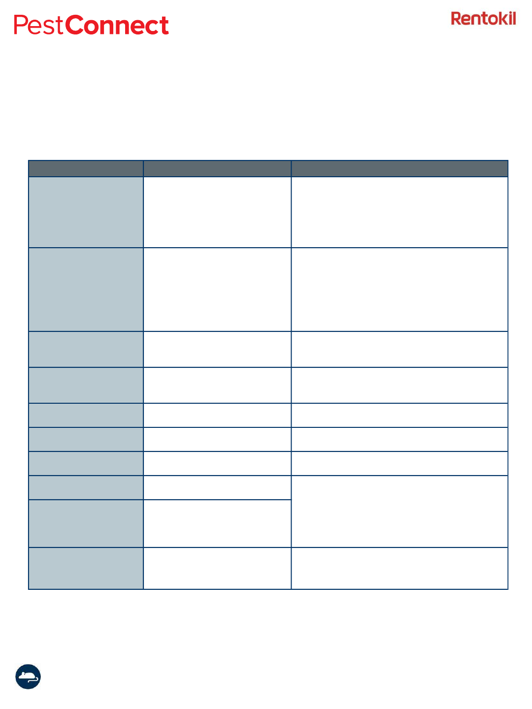
Troubleshooting
Issue
Cause
Solution
No Red LED when Radar is
switched on
Insufficient Power Change the battery
Check that the connector is in tact
and that the cable is routed under
the red door beam.
Radar switched off and on
too quickly.
Switch the Radar off and wait for 5
seconds before switching back on.
Doors do not close Faulty components Enter a quality complaint before
returning the unit
Insufficient tension in the
springs or plastics causing
too much friction
(especially at low
temperatures)
Check that the spring is still located
in the red door beam
M ouse alive in the unit or
found in the electronics /
battery section
Empty or faulty CO2
canister.
Ensure that the Radar is not
damaged by the mouse. If there is
no sign of damage then replace the
CO2 can.
Radar immediately
activating when switched
on OR rapidly flashes red
without breaking the
beams
Infrared detectors are
detecting dust or other
debris.
Clean the iR sensors and black
stickers
Solenoid does not trigger Not enough power in the
battery
Change the battery
LED flashes red when
triggering the solenoid in
the technician test
Not communicating with
the radio module
Switch the Radar off and wait for 5
seconds before switching back on.
Can not activate the
Radar in technicain test
mode
Unit is in high light
conditions and the iR
sensors could be saturated
M ove out of the direct sunlight and
try again.
Instruction Manual Connect Radar 2017 Version 1.1 (GSD-100549)
Page 15
Technical Details
Connect Radar
Power Supply
Battery supply
Use only Rentokil-Initial battery pack FR18
6v output - 4 x AA cell Alkaline battery pack
-20ºC to 50ºC Operating Temperature range
Interfaces:
Local Area Network (LAN)
868-928MHz depending on local Approvals
Rentokil Initial Propriatary Application Layer Protocol
Connect Device connect ivit y
Maximum Number of Radar units
300
per Control Panel
Physical:
Dimensions
308mm x 196mm x 60mm
Material
Perrite Polypropylene PCS18E - HB rated polymer to UL94
Weight
415g (including full gas canister)
Operating Temperature
0ºC to +40ºC
Environmental rating
IP21
Mounting
Possible to mount with bracket (optional FR55)
This product contains the LongReach radio module :
FCC ID: 2AK3PGSD-500349
IC ID: 22407-GSD500349
These will be shown on the approval label attached to the product.
Instruction Manual Connect Radar 2017 Version 1.1 (GSD-100549)
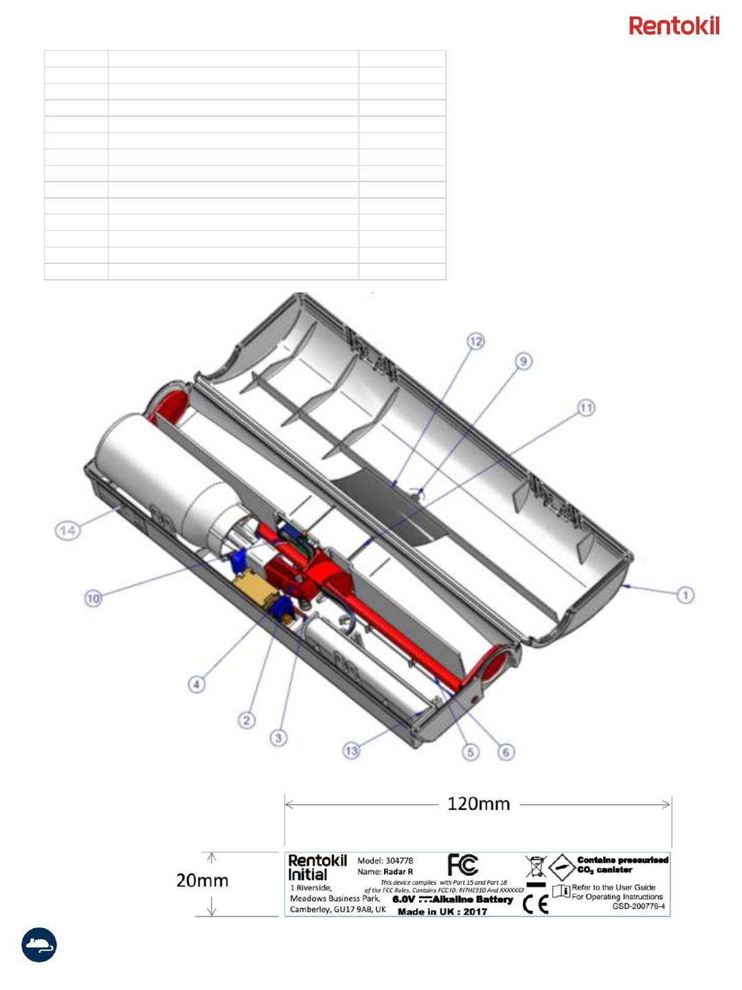
Page 16
Item Description Part Number
1 Main casing 306128
2 Lever - [Red] 360102
3 Lever spring 360106
4 Trigger - [Blue] 360103
5 Door beam 360101
6 Door beam spring 360105
9 Lens 216207
10 Circuit board assy GSD-800731
11 Radar LR Connect Approval Label GSD-200776
12 Sensor label - Black 85670
13 Battery pack 180338
14 LR Radar Antenna Support GSD-300814
15 Sensor label - Black 85670
SAMPLE LABEL