Ricoh RFAPL03 Color Copier User Manual ap c1 fax sm 00002419 eng xml
Ricoh Company Ltd Color Copier ap c1 fax sm 00002419 eng xml
Ricoh >
Contents
- 1. User Manual(Connecting to the Interface) (Short Confidential)
- 2. User Manual(Seting Telephone HandSet) (Short Confidential)
- 3. User Manual(Setting Fax Interface) (Short Confidential)
- 4. User Manual_1 (Short Confidential)
- 5. User Manual_2 (Short Confidential)
User Manual(Setting Fax Interface) (Short Confidential)
Installation Procedure
Before installing this fax unit:
Print out all data in the printer buffer.
Turn off the main power switch and disconnect the power cord and the network
cable.
InstallationInstallation-2
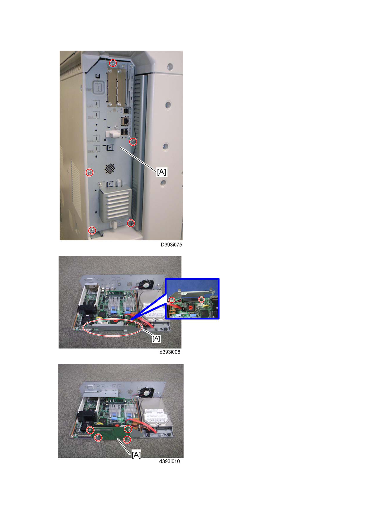
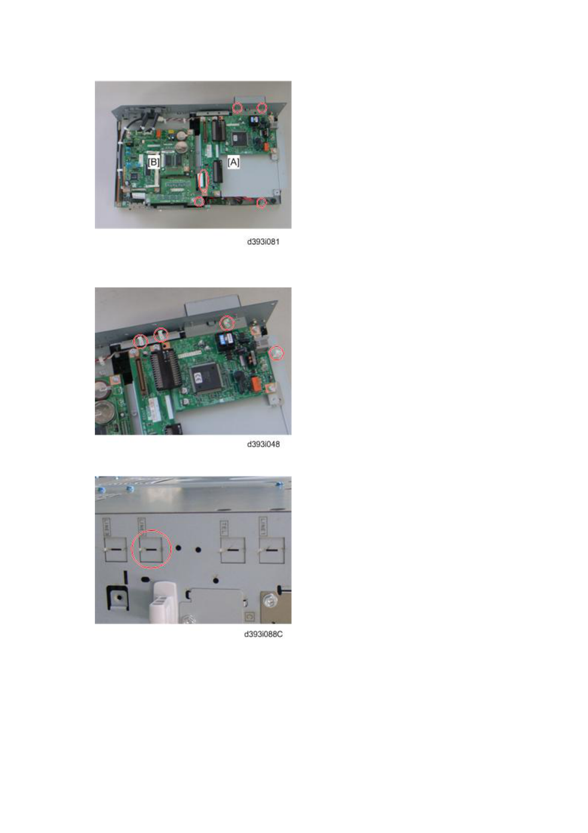
1. Remove the controller board [A] ( x 5).
2. Attach the FCU I/F board bracket [A] to the controller board ( x 2).
InstallationInstallation-3
The molding cover is removed.
3. Attach the FCU I/F board [A] to the FCU I/F board bracket ( x 4).
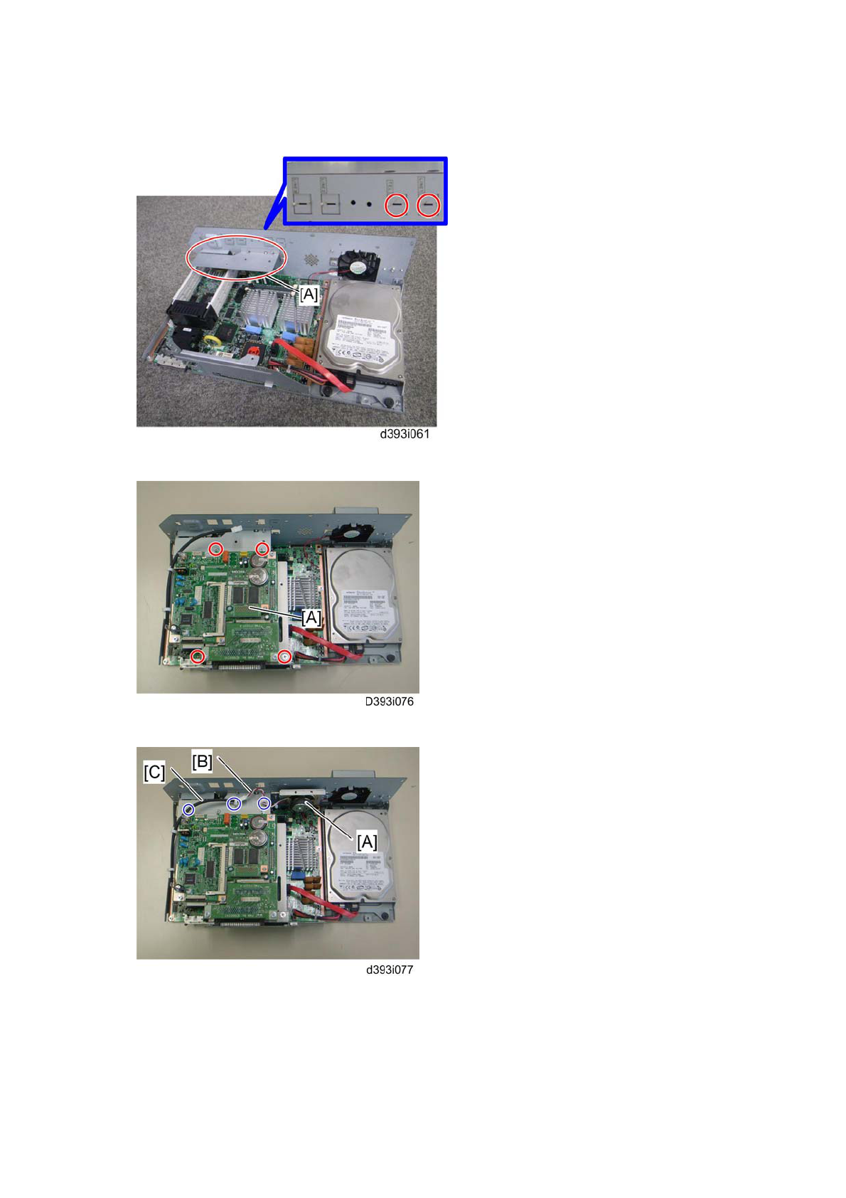
4. Attach the support bracket [A] to the controller box ( x 2).
5. Remove the “TEL” and “LINE1” covers with a screw driver.
6. Install the FCU [A] to the controller board ( x 4).
7. Install the speaker [A] to the controller box (x 2) and connect the speaker cable
[B] with the speaker relay cable [C] ( x 3).
InstallationInstallation-4
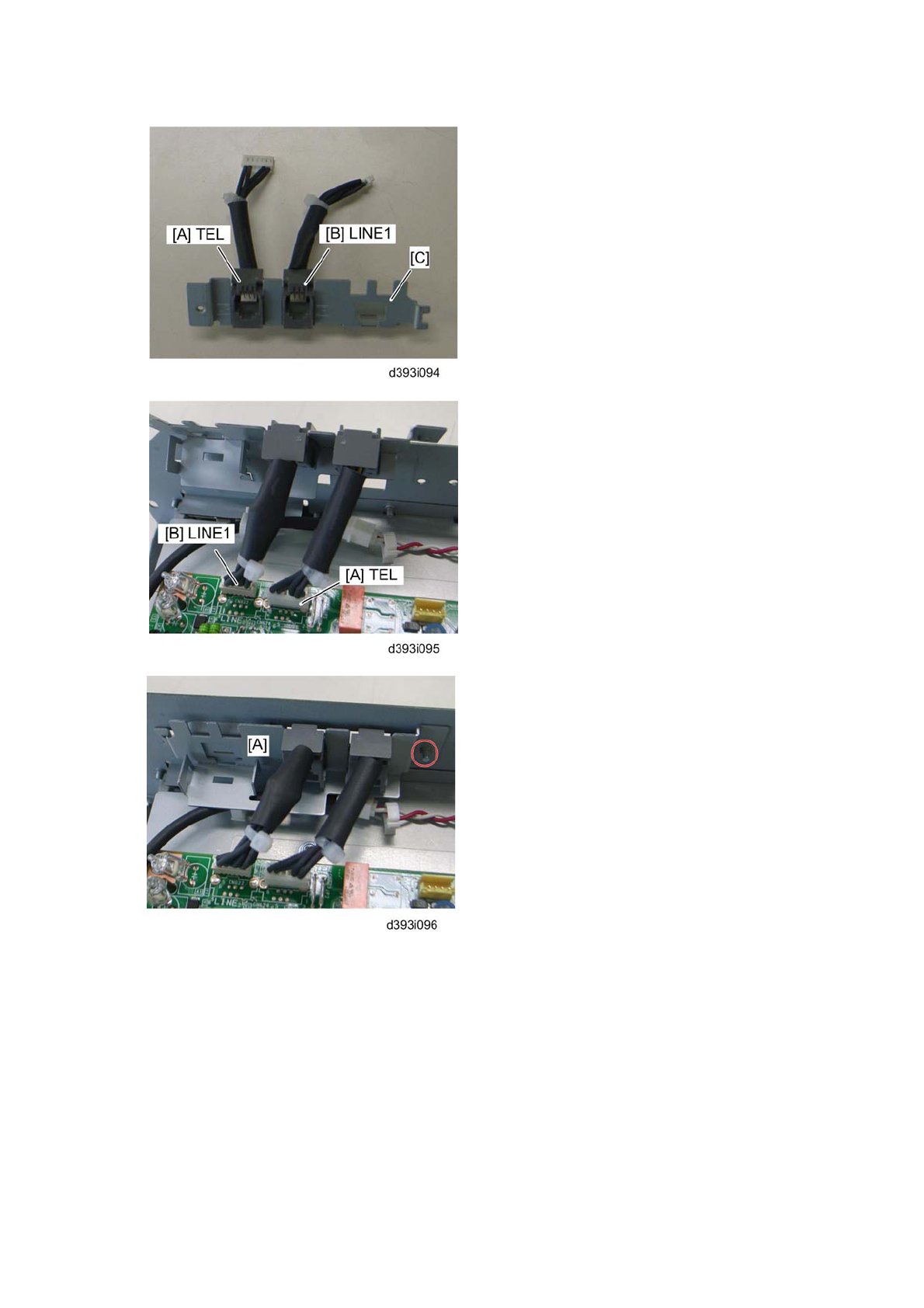
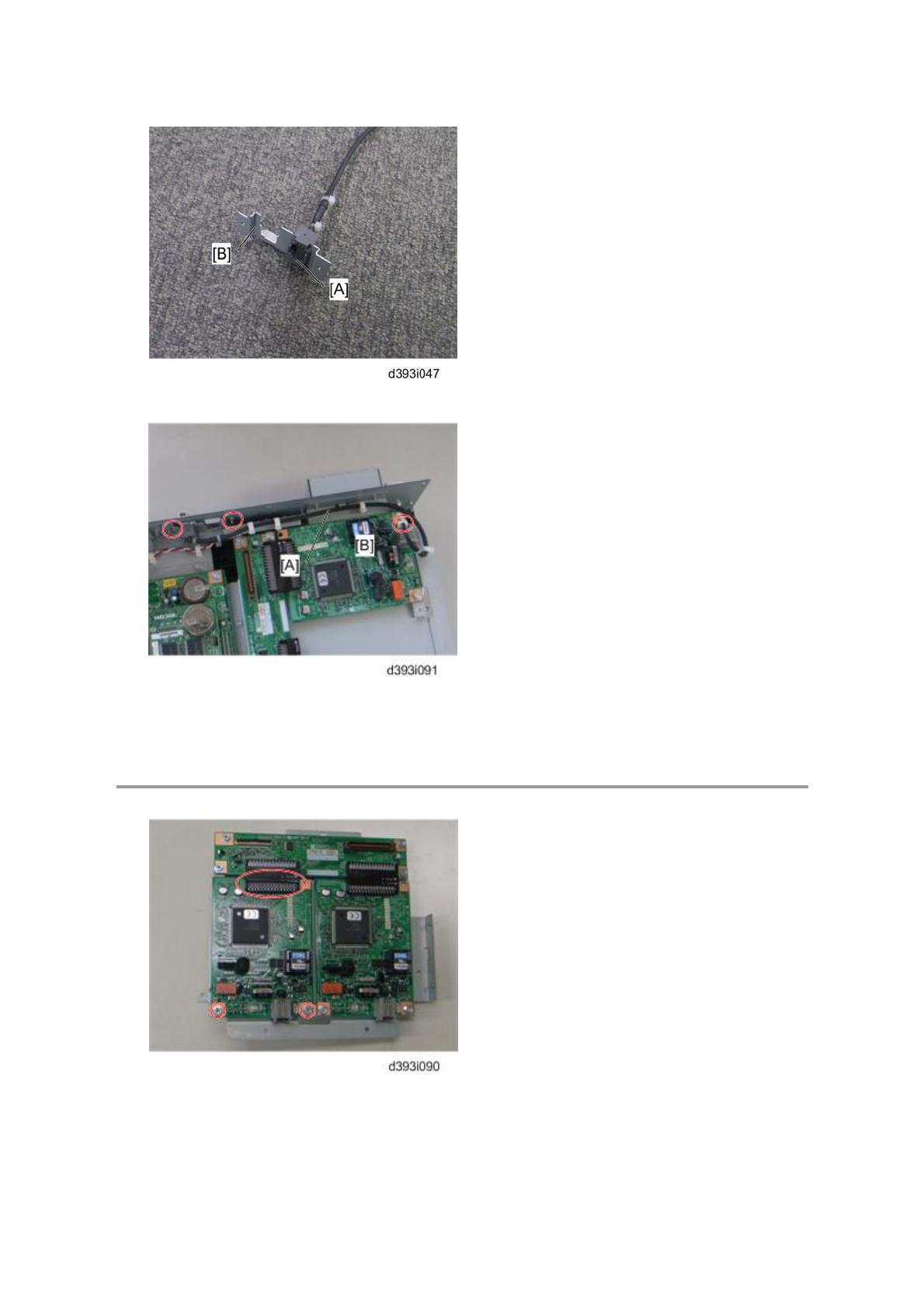
8. Connect the two modular harnesses [A] [B] to the modular bracket [C].
9. Connect the two modular harnesses [A] [B] to the FCU.
10. Attach the modular bracket [A] to the controller box (x 1).
InstallationInstallation-5
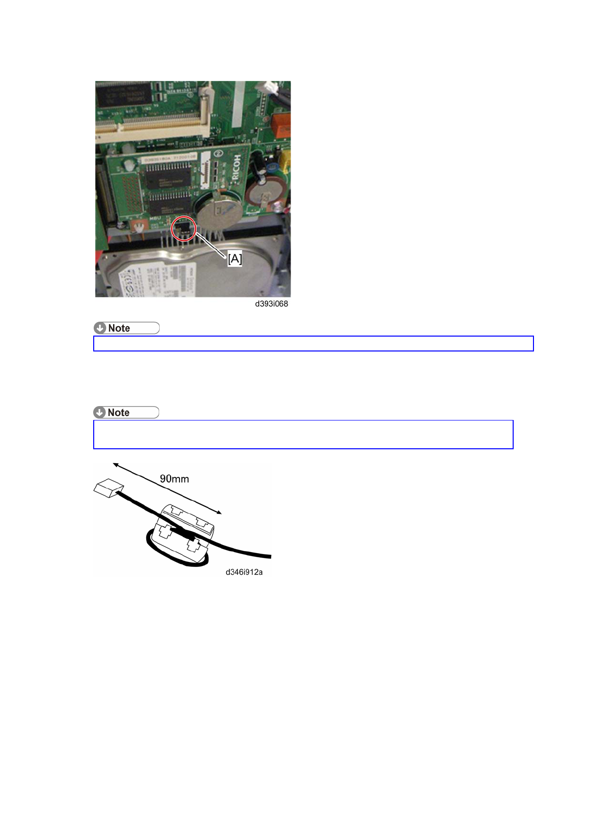
11. Switch the MBU battery jumper switch [A] to “ON” position.
Make sure that the MBU board is firmly connected to the FCU.
12. Reinstall the controller box.
13. Attach the handset support bracket and handset bracket to the copier, and then
connect the handset cord with the ferrite core to the "TEL" jack if you install the
handset to the machine.
For details, refer to the "Hand Set Installation" in the Service Manual for the Fax
Unit (D393).
14. Attach the ferrite core to the telephone cord.
15. Connect the telephone cord to the "LINE 1" jack.
InstallationInstallation-6
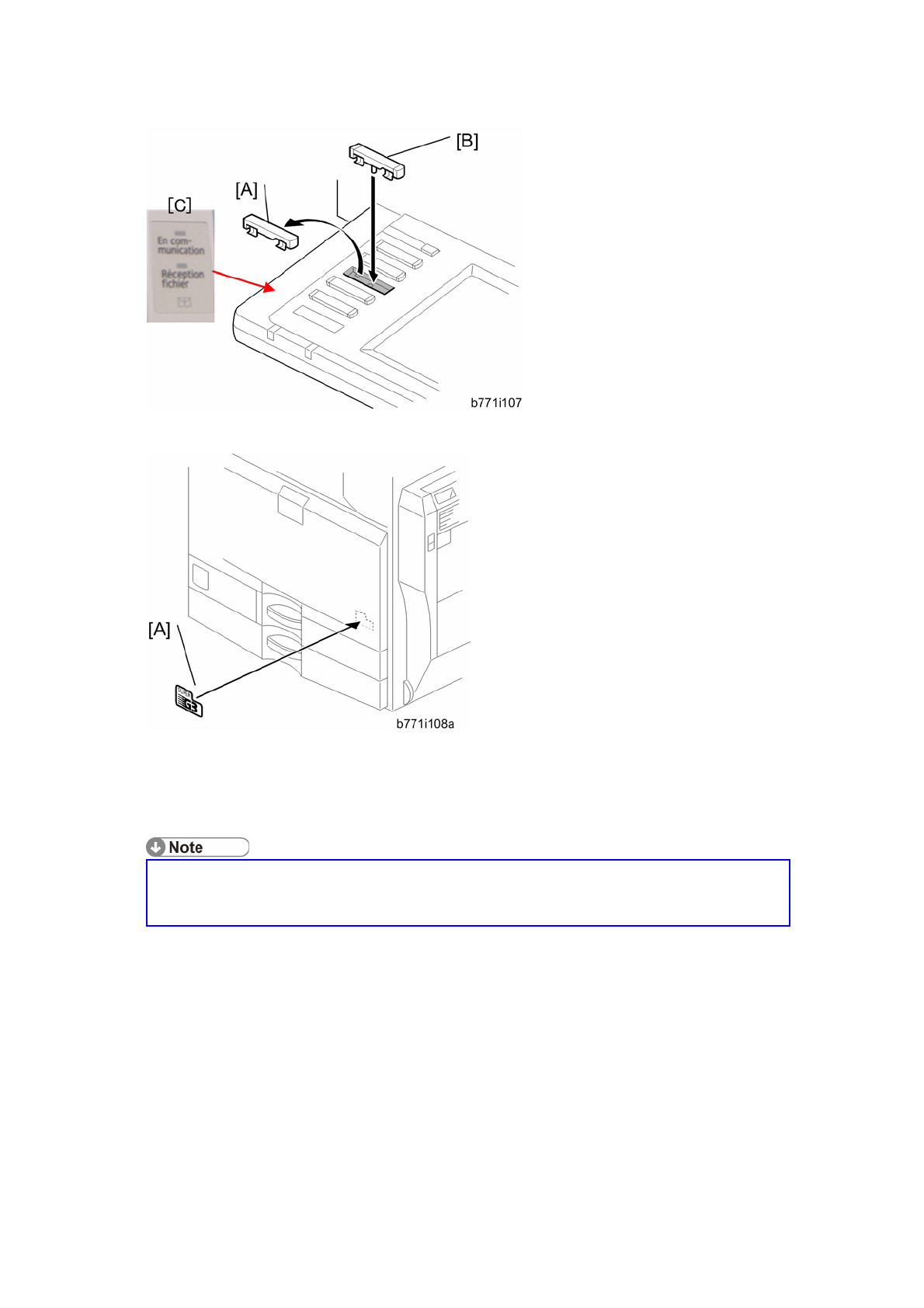
16. Replace bottom from the third key-slot cover [A] to the fax key [B].
17. Attach the Multi-Language Decals [C] (EU only).
18. Attach the decal [A] (SUPER G3) to the front door.
19. Attach the serial number decal under the copier serial number decal on the rear
cover of the machine.
20. Attach FCC decal on the rear cover of the machine (NA only).
21. Put the power plug into the outlet and turn on the main power of the machine.
Make sure that the outlet is grounded.
"SRAM formatted" shows on the operation panel after you have turned the
main switch on. Turn the main switch off and on again for normal use.
22. Make sure that the date and time are correctly set.
InstallationInstallation-7
G3 Interface Unit (D393)
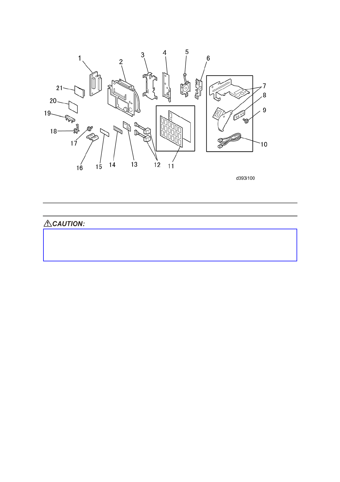
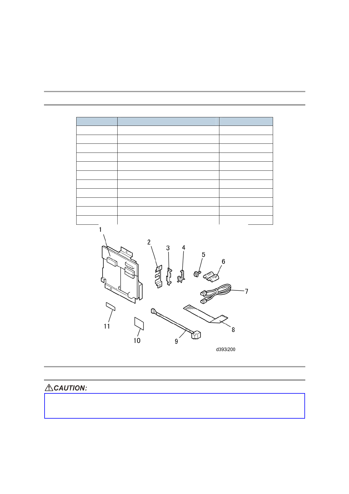
Component Check
Check the quantity and condition of the components against the following list.
No. Description Q’ty
1 SG3 Interface Unit 1
2 Modular Bracket for SG3 1
3 Clamp 2
4 Clamp 4
5 Screw: M3x6 6
6 Ferrite Core 1
7 Telephone Cable (NA only) 1
8 Flat Cable 1
9 Harness 1
10 EMC Address Decal (EU only) 1
11 FCC Decal (NA only) 1
Installation Procedure
Before installing this optional unit:
Print out all data in the printer buffer.
Turn off the main switch and disconnect the power cord and the network cable.
You can add two more SG3 boards to this model. Follow the procedures for adding
the single SG3 board installation or double SG3 boards installation as a customer
InstallationInstallation-8
needs.
For Installing the single G3 Board
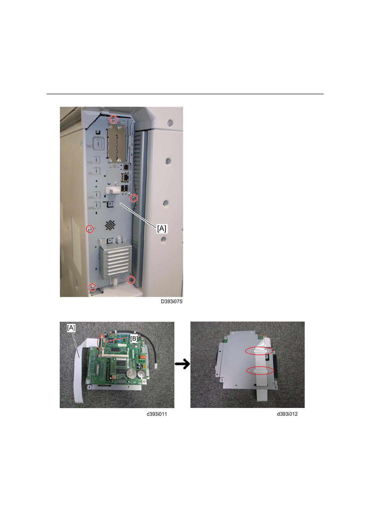
1. Remove the controller box [A] ( x 5).
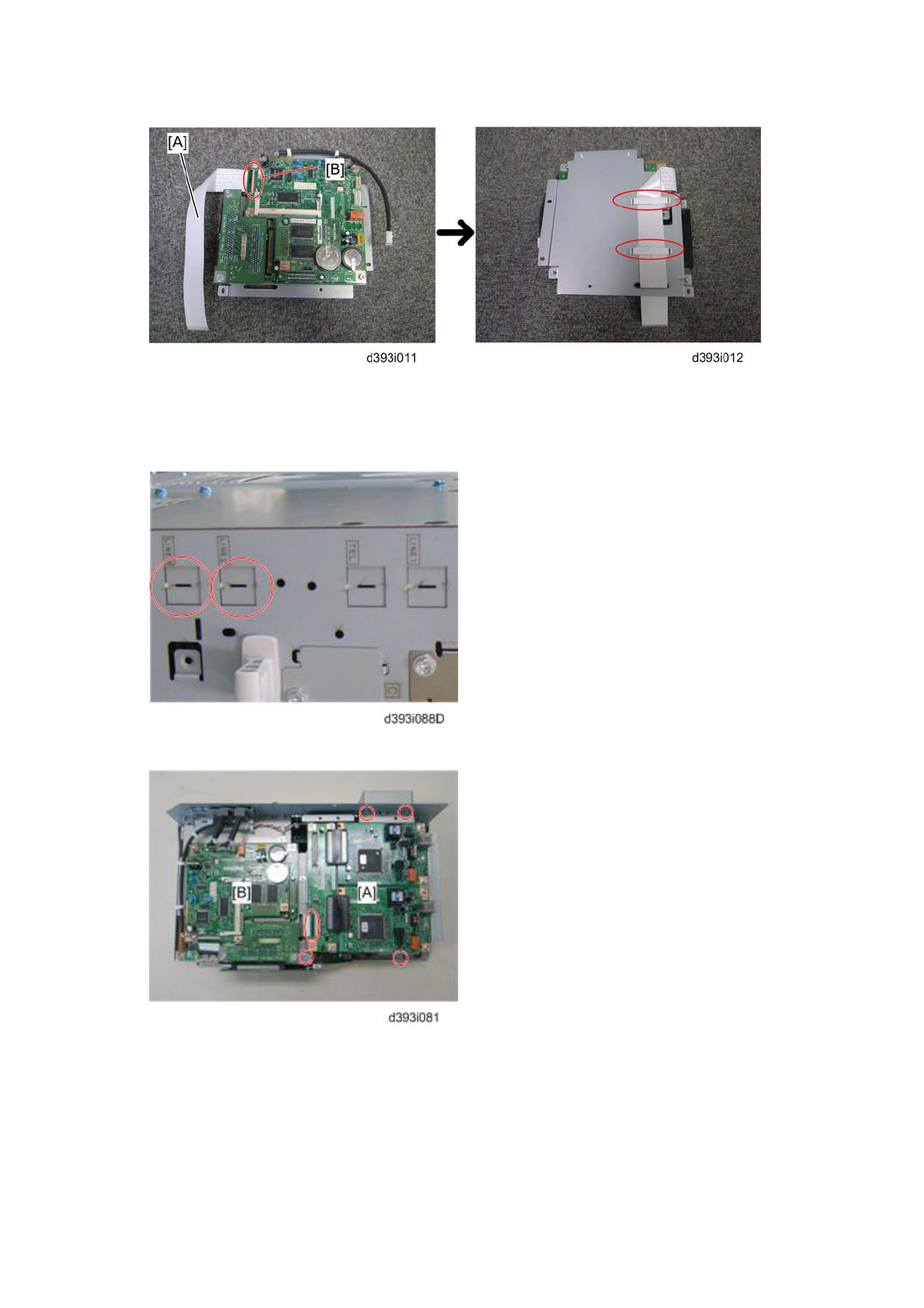
2. Attach one end (short length) of the flat cable [A] to the connector [B] of the FCU
board.
3. Hold the flat cable with two clamps and pass the other end of the flat cable
through the cutout as shown above.
InstallationInstallation-9
4. Connect the SG3 interface unit [A] to the controller board [B] with the flat cable
( x 4).
5. Attach four clamps to the brackets.
6. Remove the "LINE2" cover with a screwdriver.
InstallationInstallation-10
7. Attach the socket of harness [A] (LINE2) to the modular bracket [B] for SG3.
8. Connect the harness [A] to the SG3 interface unit [B] ( x 4).
9. Attach the modular bracket for SG3 to the controller box ( x 2).
10. Reinstall the controller box.
For Installing the Double G3 Boards
1. Remove one of SG3 boards from the SG3 interface units and then attach the
SG3 board to the other SG3 interface unit ( x 2).
2. Remove the controller box.
InstallationInstallation-11
3. Attach one end (short length) of the flat cable [A] to the connector [B] of the FCU
board.
4. Hold the flat cable with two clamps and pass the other end of the flat cable
through the cutout as shown above.
5. Remove the "LINE2" cover and "LINE3" cover with a screwdriver.
6. Connect the SG3 interface unit [A] to the controller board [B] with the flat cable
( x 4).
InstallationInstallation-12
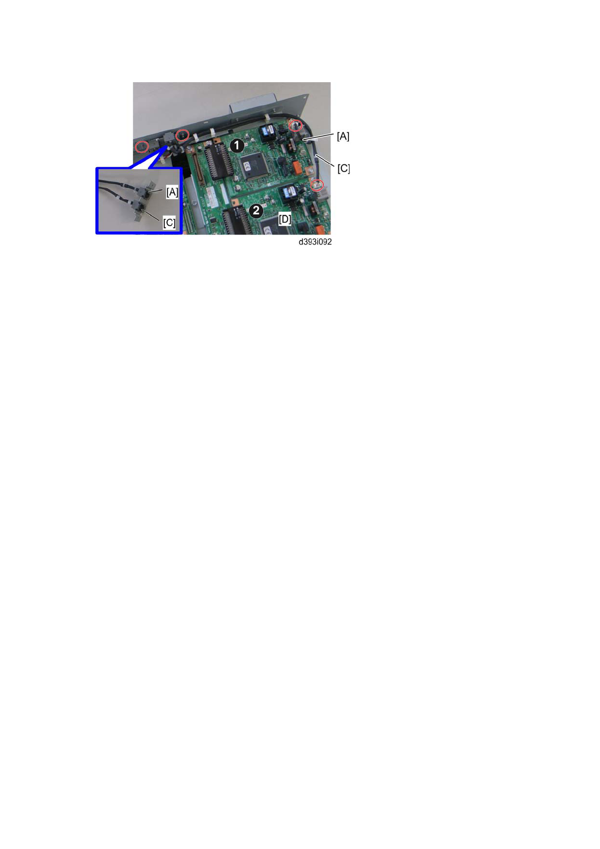
7. Attach the socket of harness [A] (LINE2) and the socket of harness [C] (LINE3)
to the modular bracket for SG3.
8. Connect the harness [A] (LINE2) to the first SG3 board ¶ and the harness [C]
(LINE3) to the second SG3 board · ( x 4).
9. Attach the modular bracket for SG3 to the controller box ( x 2).
10. Reinstall the controller box.
11. Attach the ferrite core to the telephone cord for single SG3 board installation, or
the two ferrite cores to the telephone cords for double-SG3 board installation.
12. Connect the telephone cord to the "LINE 2" jack for single SG3 board installation,
or connect the telephone cords to the "LINE2" and "LINE3" jacks for double-SG3
board installation.
13. Connect the power plug to a power outlet and turn on the main power switch.
14. Enter the service mode. Set bit 1 of communication switch 16 to “1”
(SP1-104-023).
15. Set bit 3 of communication switch 16 to "1" (SP1-104-023) if you have installed
two SG3 boards.
16. Exit the service mode.
17. Turn the main power switch off and on.
18. Print out the system parameter list. Then check that “G3” shows as an option.
19. Set up and program the items required for PSTN-2 communications.
InstallationInstallation-13
Fax Unit Options
Memory Unit (G578)
1. Rear cover (* "Installation Procedure" in the "Fax Unit (D393)")
2. Controller box left cover (* "Installation Procedure" in the "Fax Unit (D393)")
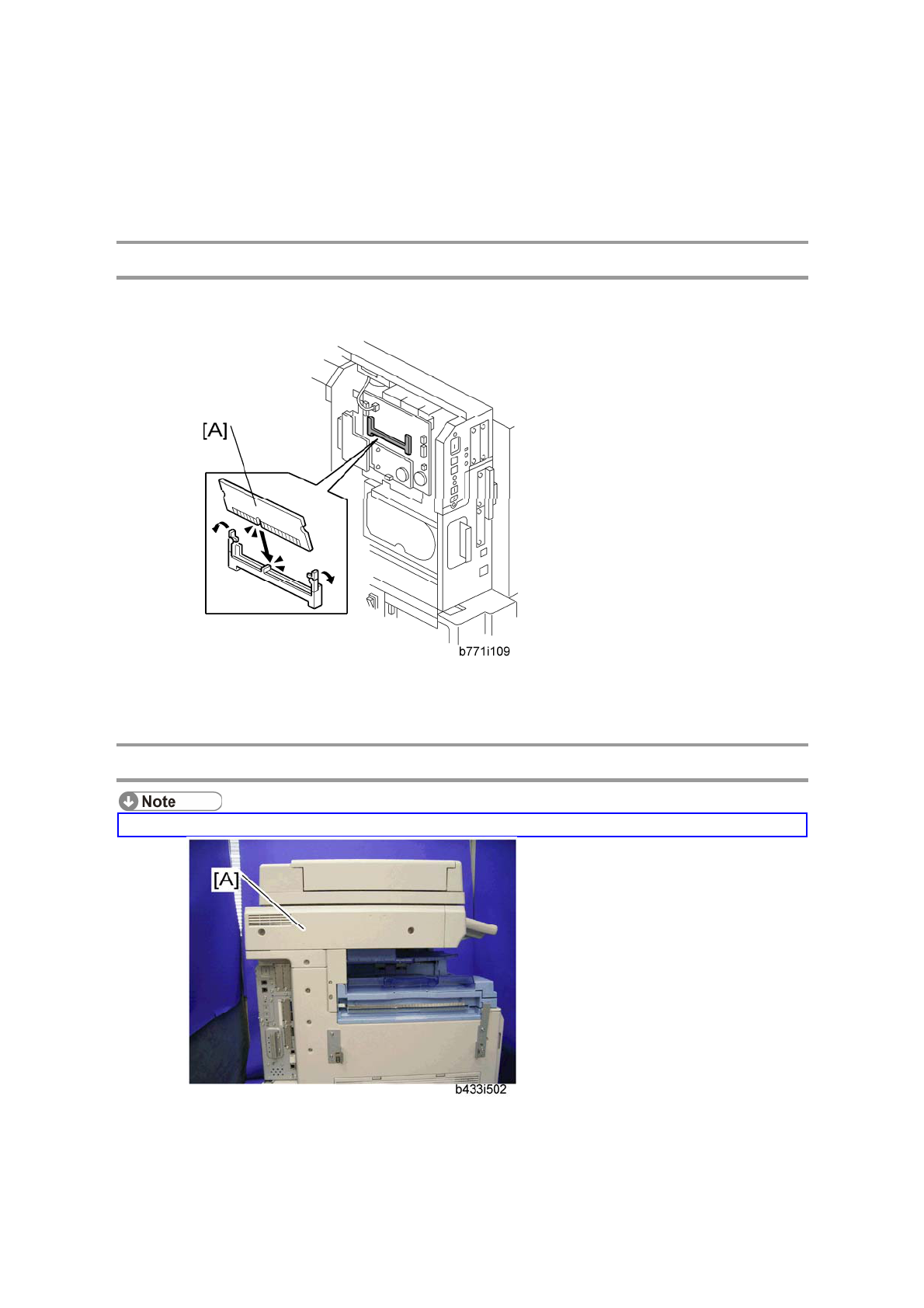
3. Intall the memory option [A] to the FCU.
4. Re-aasemble the machine
Handset (B433)
The optional handset is available for the U.S. version only.
1. Remove the scanner left cover [A] ( x 2).
InstallationInstallation-14
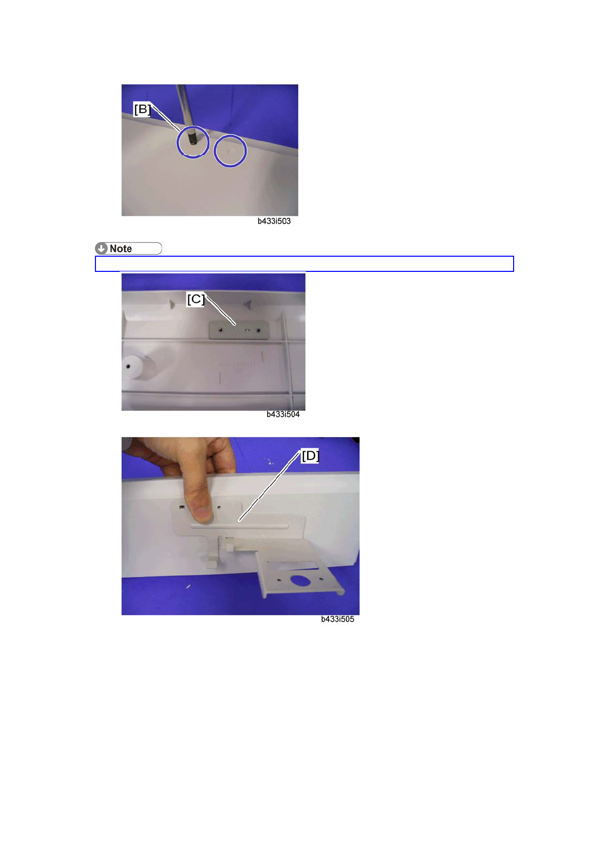
2. Make two holes in the scanner left cover.
Drill a hole from the outside of the cover with a screwdriver.
3. Attach the hand set support bracket [C] inside the scanner left cover.
4. Hold the handset bracket [D] and handset support bracket (set inside the
scanner left cover).
5. Secure the handset bracket [D] ( x 2).
InstallationInstallation-15
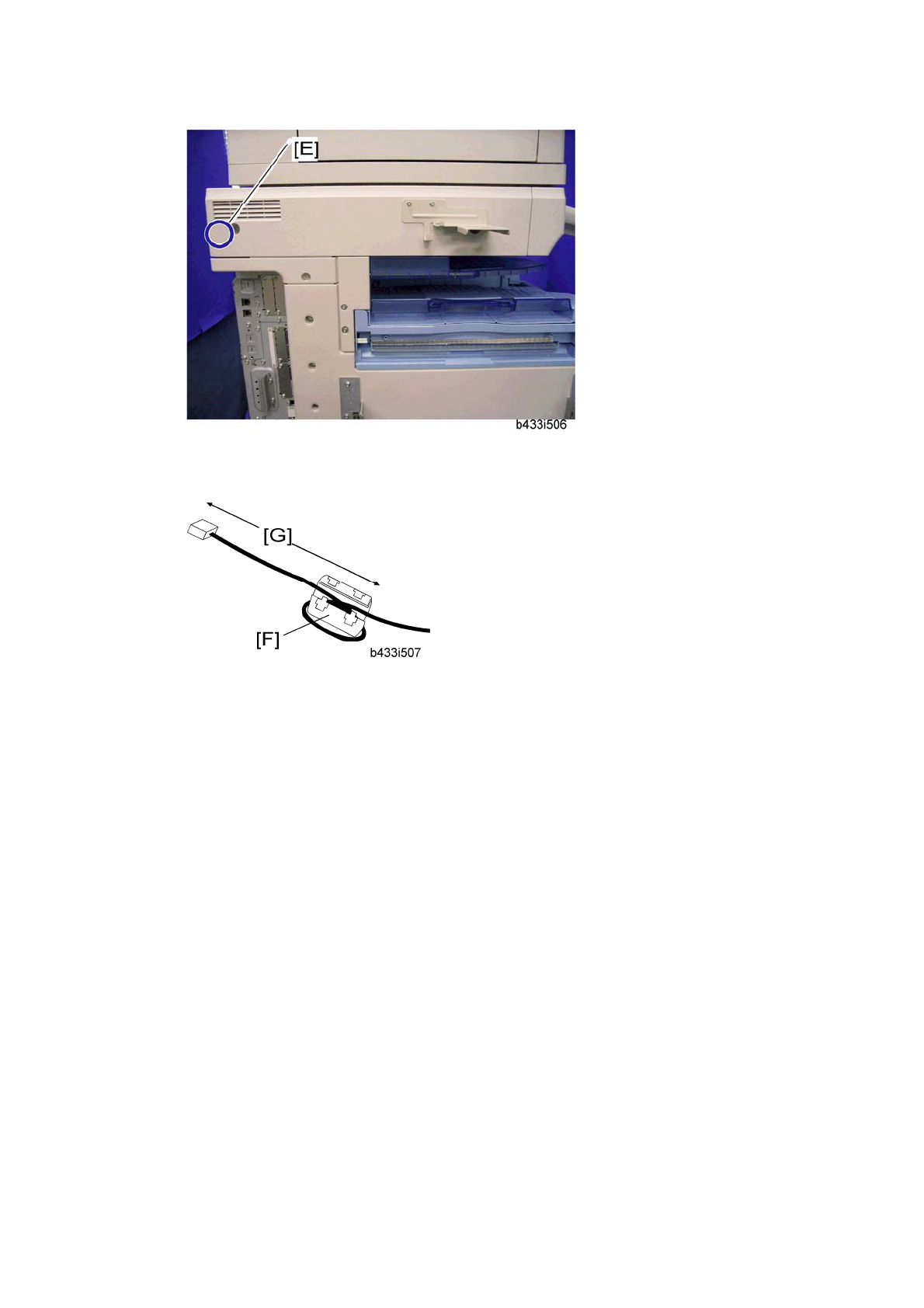
6. Install the scanner left cover on the machine.
7. Attach the clamp to the location [E].
8. Set the handset on the handset bracket.
9. Put the ferrite core [F] on the handset cord as shown. The length [G] must be 90
mm.
10. Clamp the hand set cord.
11. Connect the handset cable to the “TEL” jack at the rear of the machine.
InstallationInstallation-16