Risco RK825DTGL IWISE DT 25M ACT≷, US User Manual 5IN2635 iWISE 815 825DTGL ai
Risco Ltd. IWISE DT 25M ACT≷, US 5IN2635 iWISE 815 825DTGL ai
Risco >
User Manual
Note: For Corridor installations, select position to ”L” and mount the
detector at 2.5m/8’2” height.
FRANÇAIS
Remarque: Pour les installations en couloir, sélectionnez la position
“L” et appliquez l'option de montage à hauteur de 2,5m/8’2”.
Para instalaciones de Pasillo, seleccione la posición “L” e
instale a 2.5m/8’2” de altura.
Nota:
iWISETM
Models: RK815DTGL
RK825DTGL
© RISCO Group 03/2017 5IN2635
Standard Limited Product Warranty (“Limited Warranty”)
RISCO Ltd. (“RISCO") guarantee RISCO’s hardware products (“Products”) to
be free from defects in materials and workmanship when used and stored
under normal conditions and in accordance with the instructions for use
supplied by RISCO, for a period of (i) 24 months from the date of delivery of
the Product (the “Warranty Period”). This Limited Warranty covers the Product
only within the country where the Product was originally purchased and only
covers Products purchased as new.
Contact with customers only. This Limited Warranty is solely for the benefit
of customers who purchased the Products directly from RISCO or from an
authorized distributor of RISCO. RISCO does not warrant the Product to
consumers and nothing in this Warranty obligates RISCO to accept Product
returns directly from end users who purchased the Products for their own use
from RISCO’s customer or from any installer of RISCO, or otherwise provide
warranty or other services to any such end user directly. RISCO’s authorized
distributor or installer shall handle all interactions with its end users in
connection with this Limited Warranty. RISCO’s authorized distributor or
installer shall make no warranties, representations, guarantees or statements
to its end users or other third parties that suggest that RISCO has any
warranty or service obligation to, or any contractual privy with, any recipient
of a Product.
Remedies. In the event that a material defect in a Product is discovered and
reported to RISCO during the Warranty Period, RISCO shall accept return of
the defective Product in accordance with the below RMA procedure and, at
its option, either (i) repair or have repaired the defective Product, or
(ii) provide a replacement product to the customer.
Return Material Authorization. In the event that you need to return your
Product for repair or replacement, RISCO will provide you with a Return
Merchandise Authorization Number (RMA#) as well as return instructions. Do
not return your Product without prior approval from RISCO. Any Product
returned without a valid, unique RMA# will be refused and returned to the
sender at the sender’s expense. The returned Product must be accompanied
with a detailed description of the defect discovered (“Defect Description”) and
must otherwise follow RISCO’s then-current RMA procedure published in
RISCO’s website at www.riscogroup.com in connection with any such return.
If RISCO determines in its reasonable discretion that any Product returned
by customer conforms to the applicable warranty (“Non-Defective Product”),
RISCO will notify the customer of such determination and will return the
applicable Product to customer at customer’s expense. In addition,
RISCO may propose and assess customer a charge for testing and
examination of Non-Defective Product.
Entire Liability. The repair or replacement of Products in accordance with
this Limited W arranty shall be RISCO’s entire liability and customer’s sole
and exclusive remedy in case a material defect in a Product is discovered
and reported as required herein. RISCO’s obligation and this Limited
Warranty are contingent upon the full payment by customer for such Product
and upon a proven weekly testing and examination of the Product
functionality.
Limitations. This Limited Warranty is the only warranty made by RISCO with
respect to the Products. The warranty is not transferable to any third party.
To the maximum extent permitted by applicable law, this Limited Warranty
shall not apply and will be void if: (i) the conditions set forth above are not
met (including, but not limited to, full payment by customer for the Product
and a proven weekly testing and examination of the Product functionality);
(ii) if the Products or any part or component thereof: (a) have been subjected
to improper operation or installation; (b) have been subject to neglect, abuse,
willful damage, abnormal working conditions, failure to follow RISCO’s
instructions (whether oral or in writing); (c) have been misused, altered,
modified or repaired without RISCO’s written approval or combined with,
or installed on products, or equipment of the customer or of any third party;
(d) have been damaged by any factor beyond RISCO’s reasonable control
such as, but not limited to, power failure, electric power surges, or unsuitable
third party components and the interaction of software therewith or (e) any
failure or delay in the performance of the Product attributable to any means
of communication provided by any third party service provider, including, but
not limited to, GSM interruptions, lack of or internet outage and/or telephony
failure. BATTERIES ARE EXPLICITLY EXCLUDED FROM THE WARRANTY
AND RISCO SHALL NOT BE HELD RESPONSIBLE OR LIABLE IN
RELATION THERETO, AND THE ONLY WARRANTY APPLICABLE
THERETO, IF ANY, IS THE BATTERY MANUFACTURER'S WARRANTY.
RISCO does not install or integrate the Product in the end user’s security
system and is therefore not responsible for and cannot guarantee the
performance of the end user’s security system which uses the Product or
which the Product is a component of.
This Limited Warranty applies only to Products manufactured by or for
RISCO. Further, this Limited Warranty does not apply to any software
(including operating system) added to or provided with the Products or any
third-party software, even if packaged or sold with the RISCO Product.
Manufacturers, suppliers, or third parties other than RISCO may provide their
own warranties, but RISCO, to the extent permitted by law and except as
otherwise specifically set forth herein, provides its Products “AS IS”.
Software and applications distributed or made available by RISCO in
conjunction with the Product (with or without the RISCO brand), including,
but not limited to system software, as well as P2P services or any other
service made available by RISCO in relation to the Product, are not covered
under this Limited Warranty. Refer to the Terms of Service at:
https://riscocloud.com/ELAS/WebUI/UserLogin/License for details of your
rights and obligations with respect to the use of such applications,
software or any service. RISCO does not represent that the Product may not
be compromised or circumvented; that the Product will prevent any personal
injury or property loss by burglary, robbery, fire or otherwise, or that the
Product will in all cases provide adequate warning or protection. A properly
installed and maintained alarm may only reduce the risk of a burglary, robbery
or fire without warning, but it is not insurance or a guarantee that such will not
occur or will not cause or lead to personal injury or property loss.
CONSEQUENTLY, RISCO SHALL HAVE NO LIABILITY FOR ANY
PERSONAL INJURY, PROPERTY DAMAGE OR OTHER LOSS BASED ON
ANY CLAIM AT ALL INCLUDING A CLAIM THAT THE PRODUCT FAILED
TO GIVE WARNING. EXCEPT FOR THE WARRANTIES SET FORTH
HEREIN, RISCO AND ITS LICENSORS HEREBY DISCLAIM ALL EXPRESS,
IMPLIED OR STATUTORY, REPRESENTATIONS, WARRANTIES,
GUARANTEES, AND CONDITIONS WITH REGARD TO THE PRODUCTS,
INCLUDING BUT NOT LIMITED TO ANY REPRESENTATIONS,
WARRANTIES, GUARANTEES, AND CONDITIONS OF
MERCHANTABILITY, FITNESS FOR A PARTICULAR PURPOSE, TITLE
AND WARRANTIES AGAINST HIDDEN OR LATENT DEFECTS, TO THE
EXTENT PERMITTED BY LAW. WITHOUT LIMITING THE GENERALITY
OF THE FOREGOING, RISCO AND ITS LICENSORS DO NOT
REPRESENT OR WARRANT THAT: (I) THE OPERATION OR USE OF THE
PRODUCT W ILL BE TIMELY, SECURE, UNINTERRUPTED OR
ERROR-FREE; (ii) THAT ANY FILES, CONTENT OR INFORMATION OF
ANY KIND THAT MAY BE ACCESSED THROUGH THE PRODUCT SHALL
REMAIN SECURED OR NON DAMAGED. CUSTOMER ACKNOWLEDGES
THAT NEITHER RISCO NOR ITS LICENSORS CONTROL THE TRANSFER
OF DATA OVER COMMUNICATIONS FACILITIES, INCLUDING THE
INTERNET, GSM OR OTHER MEANS OF COMMUNICATIONS AND THAT
RISCO’S PRODUCTS, MAY BE SUBJECT TO LIMITATIONS, DELAYS, AND
OTHER PROBLEMS INHERENT IN THE USE OF SUCH MEANS OF
COMMUNICATIONS. RISCO IS NOT RESPONSIBLE FOR ANY DELAYS,
DELIVERY FAILURES, OR OTHER DAMAGE RESULTING FROM SUCH
PROBLEMS. RISCO WARRANTS THAT ITS PRODUCTS DO NOT, TO THE
BEST OF ITS KNOWLEDGE, INFRINGE UPON ANY PATENT, COPYRIGHT,
TRADEMARK, TRADE SECRET OR OTHER INTELLECTUAL PROPERTY
RIGHT IN ANY EVENT RISCO SHALL NOT BE LIABLE FOR ANY
AMOUNTS REPRESENTING LOST REVENUES OR PROFITS, PUNITIVE
DAMAGES, OR FOR ANY OTHER INDIRECT, SPECIAL, INCIDENTAL, OR
CONSEQUENTIAL DAMAGES, EVEN IF THEY WERE FORESEEABLE OR
RISCO HAS BEEN INFORMED OF THEIR POTENTIAL.
ENGLISH
iWISE RK815DTGL/RK825DTGL detectors are the ultimate
motion detectors for professional installations, incorporating Anti-CloakTM
Technology (ACTTM), adhering to new environmentally friendly guidelines.
RK815DTGL/RK825DTGL detectors are available in 10m,
15m and 25m models, and include built-in end-of-line (EOL) resistors to
simplify installation.
Installation / Maintenance
1. Mounting - The RK815DTGL/RK825DTGL can be
mounted either on a flat surface or on a wall corner (corner mounting).
• Using a suitable tool, open the following knockouts on the detector’s
base (see Figure 1).
Note: Back tamper “Breakable plate” not applicable in this version.
2. To select the correct vertical adjustment position for wide angle lens,
use the scale on the bottom left hand side of the PCB as follows:
Mounting height and scale position based on room size:
Mounting Height L - LONG S - SHORT
For RK815DTGL
2.1m-2.7m (6'11"-8’10") 15m (50’) 6m (20’)
For RK825DTGL
1.8m-2.0m (5'11"-6’7") 25m (82’) 8m (26’)
3. Set jumpers (see Jumper Setting section).
Note: Reset the detector after each change made to the settings.
4. Install the front cover back to its place (in a reverse sequence of
the removal.
5. Perform a Walk test (see Walk Test section).
6. Changing Lenses (see Figure 2).
Terminal Wiring (Figure 5)
Terminal Description
- 12 + 12VDC Input
ALARM N.C. Relay
TAMPER N.C. Tamper switch
FAULT/AM
Not applicable in this version.
LED LED operation remote control
When an ”Activation Signal”** is applied to the LED
input terminal, all LEDs will be disabled.
LEDs are enabled if nothing is connected (unless LED
jumper is OFF) or 0V/12V is applied (according to the
LED/SET Input Jumper position, 12V or 0V).
**Activation Signal-
If 12VDC is applied, and the LED/SET Input Jumper is on 12V position
- Or -
0V is applied and LED/SET Input Jumper is on 0V position
Jumper Settings
Jumper Function
See Terminal Wiring section, LED Terminal
Walk Test
1. Two minutes after applying power (warm-up period), walk test the
Detector over the entire protected area to verify proper operation of
the unit (see Figure 6).
2. The MW range can be adjusted by using the potentiometer located
on the PCB. It is important to set the potentiometer to the lowest
possible setting that will still provide enough coverage for the inner
boundary protected area (see Figure 4).
MW range adjustment (Figure 4)
MIN MAX
LEDs Display
LED State Description
Yellow On PIR detection
Flashing Trouble in PIR channel
Green On MW detection
Flashing Trouble in MW channel
Red On ALARM
All LEDs Flashing
(consecutively)
At power-up, the LEDs will flash
consecutively until the end of the warm-
up period (2-3 minutes).
Technical Specification
Electrical
Current consumption 16mA at 12VDC (Typical)
41mA at 12VDC (max.)
Voltage requirements 9 -16VDC***
Alarm contacts 24VDC, 0.1A
Tamper contacts 24VDC, 0.1A
Environmental
RF immunity According to EN50130-4
Operating temperature 0°C to 49°C (14°F to 131°F)
Storage temperature -20°C to 60°C (-4°F to 140°F)
Optical
Filtering White Light Protection
Physical
Size 127.6 x 64.2 x 46.6 mm (5 x 2.5 x 1.84 in.)
Weight 120 gr. (4.2 oz.)
*** Power to be supplied by 5A max. power source using safety
approved wires, with a min Gauge of 20AWG.
Les détecteurs iWISE RK815DTGL/RK825DTGL sont
les tout derniers modèles de détecteurs de mouvement conçus pour
établissements professionnels. Ils intègrent la technologie de
l'Anti-Cloak™ (ACT™), répondant aux nouvelles directives de
protection de l'environnement.
Disponibles en modèles 10m, 15m et 25m, les détecteurs iWISE
RK815DTGL/RK825DTGLcomprennent des résistances
de Fin de ligne (EOL = end-of-line) intégrées qui facilitent l'installation.
Installation
1. Montage – RK815DTGL/RK825DTGL peut être installé
soit sur une surface plane soit en coin (gauche ou droit).
• A l’aide d’un outil adequat, ouvrez les pastilles pré-percées
correspondantes sur la báse du dé tecteur (cf. Figure 1).
2. Pour définir le bon réglage vertical, positionnez l'appareil en
LENTILLE GRAND ANGLE. Servez-vous de l'échelle figurant sur le
côté inférieur gauche de la carte PCB (cf. Figure 6) comme suit:
Hauteur de montage et position selon la taille de la pièce:
Hauteur de montage L - LONG C - COURT (SHORT)
Pour RK815DTGL
2,1m-2,7m (6'11"-8’10") 15m (50’) 6m (20’)
Pour RK825DTGL:
1.8m-2,0m (5'11"-6’7") 25m (82’) 8m (26’)
3. Réglez les cavaliers (cf. § Réglage des cavaliers).
4. Replacez le couvercle frontal (en inversant pour cela l'ordre des
étapes de la procédure de retrait).
5. Exécutez un test de passage (cf. § Test de passage).
6. Changement des lentilles (cf. Figure 2).
Câblage des Terminaux (cf. Figure 5)
Terminal Description
- 12 + Entrée 12VCC
ALARM Relais N.F., 24VCC, 0,1A
TAMPER Relais N.F., 24VCC, 0,1A
Terminal Description
FAULT / AM Non applicable dans cette version.
LED Contrôle à distance des indicateurs LED
Lorsqu'un ”Signal d'Activation”** est appliqué à
l'entrée LED du bloc des terminaux ou bornes de
connexion, les indicateurs LED se désactivent
(cf. aussi l'entrée Test automatique dans le
tableau consacré au Réglage des cavaliers).
Les voyants LED sont activés si rien n'est relié
(sauf si le cavalier LED est éteint (OFF).
**Signal d'Activation-
Si une tension de 12VCC est appliquée et que le Cavalier d'entrée
LED/SET est en position 12V -Ou-
Si la Terre (GND) est reliée, le Cavalier d'entrée LED/SET est en
position 0V.
Réglage des cavaliers
Cavalier Fonction
SW1-1: LED Définit le fonctionnement des indicateurs LED du
détecteur.
Marche (ON)
(Défaut)
L'activation des indicateurs LED dépend du
paramétrage du contrôle à distance de leur
fonctionnement (cf. § Câblage des Terminaux, borne
de connexion LED).
Arrêt (OFF) Les indicateurs LED sont désactivés.
SW1-2: ACT Définit si le mode ACT est activé ou non
Marche (ON) ACT activé.
Important! N'utilisez pas le mode ACT™ dans une
zone en dehors de laquelle le passage d'objets
en mouvement vous paraît logique et attendu, un
couloir par exemple.
Arrêt (OFF)
(Défaut)
ACT désactivé.
SW1-3: Green Line
RK815DTGL/RK825DTGL comprend une caractéristique
‘Green Line’, concept qui permet aux détecteurs de respecter les
directives environnementales en évitant les émissions excessives.
Marche (ON)
"Green Line" activée: Pour désactiver le module HF
pendant les périodes d'inactivité, les indicateurs LED
doivent être désactivés à distance.
Arrêt (OFF)
(Défaut)
Green Line désactivé (OFF): le canal HF est
constamment activé.
SW1-4: Non applicable dans cette version.
J1 - Alarm EOL Les cavaliers J1, J2 permettent de sélectionner
J2 - Tamper EOL les résistances EOL (fin de ligne)
d'Autoprotection, Alarme et FAULT/AM (1K,
2,2K, 4,7K, 5,6K, 6,8K et 12K) en fonction de la
centrale (cf. Figure 3 ci-dessous).
Suivez les indications du diagramme de connexion
du bloc des terminaux de la Figure 3 pour relier le
détecteur à une zone EOL Double (DEOL).
J4 - Entrée Détermine la polarité de l'entrée externe.
LED/SET
Cf. § Câblage des Terminaux, bornes de connexion
LED (Mise en service).
Cf. § Câblage des Terminaux, bornes de connexion
LED (Mise en service).
Test de passage
1. Deux minutes après avoir réalisé la mise sous tension (séquence
d'échauffement), effectuez un test de passage pour vérifier l'efficacité
du détecteur sur la totalité de la zone à protéger.
2. Assurez-vous d'avoir bien réinstallé le couvercle frontal avant de
mettre le détecteur sous tension (cf. Figure 6).
3.Le potentiomètre situé sur la carte PCB permet de régler la portée de
détection hyperfréquence. Il est important de régler le potentiomètre
sur le niveau le plus bas possible qui fournira cependant une couverture
suffisante sur la totalité de la zone à protéger.
Réglage de la portée HF (cf. Figure 4)
MIN MAX
Affichage LED
LED Position Signification
Jaune Allumée (ON) Détection IRP
Clignotante Panne de canal IRP
Verte Allumée (ON) Détection HF (hyperfréquence)
Clignotante Panne de canal HF
Rouge Allumée (ON) Indique une ALARME
Toutes
diodes LED Clignotante
(l'une après
l'autre)
Lors de la mise sous tension, les
diodes LED clignotent de manière
ininterrompue, l'une après l'autre,
jusqu'à la fin de la séquence
d'échauffement (2 à 3 minutes).
Spécifications techniques
Electriques
Consommation électrique 14.8 mA à 12VCC (en utilisation
typique)
39.5 mA à 12VCC (max. avec
tous les voyants LED allumés)
Tension requise 9 -16VCC
Contacts d'alarme 24VCC, 0,1A
Temps minimal de changement d’état: 2.2 seconds
Contacts d'autoprotection 24VCC, 0,1A
Rétsistance de la boucle de Détection:
Etat ouvert: plus que 10
Etat fermé: moins que 18ohm
Ondulations résiduelles maximales
admissibles:
0.25 créte à créte
Environnementales
Immunité RF Selon EN50130-4
Température de fonctionnement De 0ºC à 49ºC (14ºF à 131ºF)
Température de stockage De -20ºC à 60ºC (-4ºF à 140ºF)
Indice de protection: IP 31/IK 02
Taille du càble à utiliser: Fil de diamétre au moins 0.5 mm
pour une longueur ne dépassant
pas 300 métres
Optiques
Filtrage Protection anti-lumière blanche
Physiques
Dimensions 127.6 x 64.2 x 46.6 mm
(5 x2.5 x 1.84 in.)
Poids 120g
Organisme de certification
AFNOR CERTIFICATION: 11 rue Francis de Pressensé
93571 LA PLAINE SAINT-DENIS Cedex, http://www.marque-nf.com
CNPP: BP 2265, 27950 ST MARCEL, http://www.cnpp.com
ESPAÑOL
Los detectores RK815DTGL/RK825DTGL son la última
palabra en detectores de movimiento para instalaciones profesionales,
incorporando la tecnología Anti-Cloak™ (ACT™), adhiriéndose a las
nuevas directrices respetuosas con el medioambiente.
Los detectores RK815DTGL/RK825DTGL están disponibles
en versiones de 10m, 15m y 25m, e incluyen resistencias incorporadas
de final de línea (EOL) para simplificar la instalación.
Instalación / Mantenimiento
1. Montaje - El RK815DTGL/RK825DTGL puede montarse
en una superficie plana o en un rincón de pared (montaje en rincón).
• Usando una herramienta apropiada, abra los siguientes agujeros
pre-marcados en la base del detector (ver Figura 1).
2. Para selecccionar la posición correcta de ajuste vertical para lentes
gran angular utilice la escala en el lado izquierdo del PCB, según
se indica:
Altura de montaje y posición de la escala según el tamaño de
la habitación:
Altura de Montaje L - LONG S - SHORT
Para RK815DTGL
2.1m-2.7m (6'11"-8’10") 15m (50’) 6m (20’)
Para RK825DTGL
1.8m-2.0m (5'11"-6’7") 25m (50’) 8m (26’)
3. Configure los puentes (véase la sección Configuración de Puentes).
4. Coloque de nuevo la tapa delantera en su lugar (de modo inverso
al de retirarla)
5. Realice una prueba de Movimiento (véase la sección Prueba de
Movimiento).
6. Cambiando las Lentes (ver Figura 2).
Cableado del Terminal (ver Figura 5)
Terminal Descripción
- 12 + Entrada de 12VCC
ALARM Relé N.C.
TAMPER Conmutador del Tamper N.C.
FAULT/AM
(Fallo/AM) No se aplica en esta versión.
LED Control remoto del funcionamiento del LED
Cuando se aplica una ”Señal de Activación”** al terminal
de entrada del LED, se desactivan todos los LEDs.
Los LEDs se activan si no hay nada conectado (a menos
que el puente del LED esté en OFF) o se aplican 0V/12V
(según la posición del Puente LED/SETInput, 12V ó 0V)
**Señal de Activación-
Si se aplican 12VCC, y el puente (jumper) LED/SET INPUT está en la
posición 12V - O -
Se aplican 0V y el puente (jumper) LED/SET INPUT está en la posición 0V.
Configuración de los Puentes
Puente Función
SW1-1: LED Usado para determinar el funcionamiento de los LEDs
del detector.
ON
(Predeterm.) Los LEDs están habilitados, permitiendo el control del
LED a través del terminal de entrada del LED
OFF Los LEDs están deshabilitados.
SW1-2: ACT Usado para determinar si el modo ACT está habilitado
o deshabilitado
ON
ACT Habilitado
Importante: No use el modo ACT™ si usted espera
que haya objetos en movimiento fuera del área
protegida requerida, p.ej. un pasillo.
OFF
(Predeterm.)
ACT Deshabilitado.
SW1-3: Green Line
El RK815DTGL/RK825DTGL incluye una característica
Green Line que sigue las directivas medioambientales evitando un
exceso de emisión.
ON
La característica Green Line está habilitada: Para
desactivar el módulo de MW, los LEDs deben
deshabilitarse remotamente mediante el terminal LED.
NOTA: Cuando ‘Green Line’ está activado (MW
desactivado), el detector aún se activará (sólo PIR).
OFF
(Predeterm.)
La característica Green Line está deshabilitada: el
MW está constantemente en uso
SW1-4: SELF
TEST
(Auto Test)
Usado para testar las tecnologías de detección.
J1 - Alarm EOL
J2 - Tamper EOL
EOL (Fin de Línea)
Los puentes J1 y J2 permiten la selección de la
resistencia del Tamper y de la Alarma (1K, 2.2K,
4.7K, 5.6K, 6.8K) según el panel de control
Siga el diagrama de conexión del bloque de
terminales de la Figura 3 cuando conecte el
detector a una Zona de Doble Fin-de-Línea
(DEOL).
J4 - LED/SET
INPUT
(ENTRADA
LED/SET)
Usado para determinar la polaridad de la entrada
externa.
Véase la sección Cableado del Terminal, Terminal
LED
Véase la sección Cableado del Terminal, Terminal
LED
Prueba de Movimiento
1. Dos minutos después de la puesta en marcha (periodo de
calentamiento), haga la prueba de movimiento al detector en toda el
área protegida para verificar el correcto funcionamiento de la unidad
(véase Figura 6).
2. El rango de MW puede ajustarse mediante el potenciómetro situado
en el PCB (placa de circuito impreso). Es importante ajustar el
potenciómetro a la configuración más baja posible que aún pueda
proporcionar suficiente cobertura al límite interno del área protegida.
Ajuste del Rango de MW (véase Figura 4)
MIN MAX
Visualización de los LEDs
LED Estado Descripción
Amarillo Encendido Detección PIR
Parpadeando Problema en el canal PIR
Verde Encendido Detección MW
Parpadeando Problema en el canal MW
Rojo Encendido ALARMA
Todos los LEDs Parpadeando
(sucesivamente) Al poner en marcha, los LEDs
parpadearán consecutivamente
hasta el final del periodo de
calentamiento (2-3 minutos).
Especificaciones Técnicas
Eléctricas
Consumo de corriente 16mA a 12VCC (Típico)
41mA a 12VCC (Máx.)
Requisitos de voltaje 9 -16VCC
Contactos de Alarma 24VCC, 0.1A
Contactos de Tamper 24VCC, 0.1A
Ambientales
Inmunidad a RF Según EN50130-4
Temperatura de funcionamiento 0ºC a 49ºC (14°F a 131°F)
Temperatura de almacenamiento -20ºC a 60ºC (-4°F a 140°F)
Óptica
Filtrado Protección contra luz blanca
Físicas
Tamaño 127.6 x 64.2 x 46.6 mm
(5 x 2.5 x 1.84 pul)
Peso 120 gr. (4.2 oz.)
Reinicie el detector después de que se haga un cambio en las
configuraciones.
Nota:
Nota: Volver manipulaciones "rompible placa" no se aplica en esta
versión.
Remarque: Retour falsification "cassable plaque" pas applicable
dans cette version.
A Détecteur
B Couloir
1 Trop puissant
2 Pas assez puissant
3 Réglage correct
A Detector
B Pasillo
1 Energía excesiva
2 Energía baja
3 Ajuste correcto
A Detector
B Corridor
1 Over power
2 Under power
3 Correct adjustment
Jumper Function
SW1-1: LED Used to determine the operation of the detector’s LEDs
ON
(Default)
LEDs are enabled, allowing LED control via the LED
input terminal.
OFF LEDs are disabled
SW1-2: ACT Used to determine if ACT mode is enabled or disabled
ON
ACT Enabled
Important: Do not use ACT™ mode if you are
expecting that there will be moving objects outside the
required protected area, a corridor for example.
OFF
(Default)
ACT Disabled.
SW1-3: Green Line
The RK815DTGL/RK825DTGL includes a Green Line feature
that follows environmental guidelines by avoiding surplus emission.
ON Green Line feature is enabled: To deactivate the MW
module, the LEDs must be remotely disabled by the
LED terminal.
Note: W hen ‘Green Line’ is on (Microwave off), the
detector will still activate (PIR only)
OFF
(Default)
Green Line feature in disabled: MW is constantly in
use.
SW1-4: Self
Test Not applicable in this version.
J1 - Alarm EOL
J2 - Tamper EOL
Jumpers J1 and J2 allow the selection of Tamper
and Alarm resistance (1K, 2.2K, 4.7K, 5.6K, 6.8K)
according to the control panel (see Figure 3).
Follow the terminal block connection diagram in
Figure 3 when connecting the detector to a
Double End Of Line (DEOL) Zone.
J4 - LED/SET
INPUT
Used to determine the polarity of the external input.
See Terminal Wiring section, LED Terminal
ITALIANO
I rivelatori iWISE RK815DTGL/RK825DTGLsono rivelatori
di movimento che integrano le tecnologie più avanzate per le installazioni
professionali. Questi rivelatori includono la tecnologia (ACT™) e la
funzione Green Line per evitare emissioni superflue nell’ambiente.
iRK815DTGL/RK825DTGL sono disponibili nei modelli 10,
15 e 25 metri ed hanno le resistenze di fine linea integrate nel circuito
per semplificarne al massimo l’installazione.
Installazione / Manutenzione
1. Installazione - RK815DTGL/RK825DTGL può essere
installato sia su di una superficie piana che ad angolo.
• Utilizzando uno strumento appropriato aprire i fori a sfondare, di
seguito elencati, della base del contenitore come illustrato in Figura 1.
Nota: Il foro a sfondare per il tamper antirimozione non è applicabile
in questa versione.
2. Per selezionare la posizione corretta della scheda elettronica con la lente
grandangolo montata, usare i riferimenti ( LONG / SHORT) situati nella
parte inferiore sinistra della scheda elettronica seguendo le indicazioni
della tabella di seguito illustrata:
Altezza di installazione e regolazione scheda elettronica in funzione
dell’area di copertura:
2. Para usar a posição correta de ajuste vertical para lentes de ângulo
aberto, use a escala localizada no lado esquerdo inferior do PCB,
como segue:
Altura de montagem e posição da escala baseada no tamanho
do local:
Altura de Montagem L - LONGA C - CURTA
Para RK815DTGL
2.1m-2.7m (6'11"-8’10") 15m (50’) 6m (20’)
Para RK825DTGL
1.8m-2.0m (5'11"-6’7") 25m (82’) 8m (26’)
Nota: Para instalações de Corredor, selecione a posição “L” e instale
a 2.5m/8’2” de altura.
3. Configure os jumpers (ver a seção Configuração de Jumpers).
Nota: Reajuste o detector depois de cada modificação feita nas
configurações.
4. Recoloque a tampa dianteira em seu lugar (na seqüência contrária à
da remoção)
5. Realize uma prova de Caminhada (ver a seção Prova de Caminhada).
Prova de Movimento
Importante: As distâncias podem variar de acordo com as condições
térmicas ambientais.
1. Dois minutos depois de ativar (período de aquecimento), caminhe
para testar o Detector através de toda a área protegida para verificar
a correta operação da unidade (ver Figura 6).
2. O alcance de Microondas deve ser ajustado usando-se o
potenciômetro, que está localizado no PCB. É importante colocar o
potenciômetro na configuração mais baixa possível que ainda possa
proporcionar suficiente cobertura para toda a área protegida.
Ajuste do Alcance do Microondas (ver Figura 4)
MIN MAX
Visualização dos LEDs
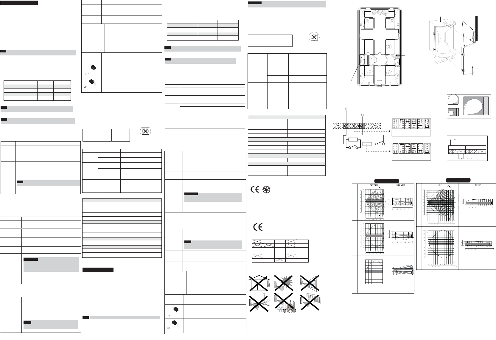
Figure 1.
Back cover - Knockouts
Range
Adjustment Bolt
Thread
Figure 2.
Lens Replacement
Sleeve Cut
Corners
Short Pin
(Facing
upwards)
6. Troca de Lentes (ver. Figura 2).
Terminais de Fiação (ver. Figura 5)
Back tamper
“Breakable” plate -
Figure 4.
Lens
3. Predisporre i ponticelli (Vedere la sezione relativa).
Nota: Ad ogni modifica delle predisposizioni/regolazioni, effettuare
sempre un reset del rivelatore rimuovendo e applicando tensione.
4. Rimontare il coperchio frontale e stringere la vite di blocco coperchio.
5. Effettuare una prova di copertura (Sezione Prova di movimento).
6. Sostituzione delle Lenti (vedere Figura 2).
Cablaggio Morsettiera (vedere Figura 5)
Morsetto Descrizione
- 12 + Ingresso di alimentazione 12V
ALARM Relé N.C.
TAMPER Interruttore N.C.
FAULT/AM Non applicabile in questa versione.
LED Controllo remoto dei LED e funzione GREEN LINE (con
ponticello GREEN LINE inserito)
Quando viene applicato un ”Segnale di Attivazione”** al
morsetto LED, tutti i LED vengono disabilitati e, se il
ponticello GREEN LINE è INSERITO, la sezione
microonda viene disabilitata.
Nota: affinché la microonda venga disabilitata non ci deve
essere alcun comando sul morsetto SET.
I LED sono abilitati se al morsetto LED non è collegato
niente (a meno che il ponticello LED sia estratto).
**Per Segnale di attivazione si intende quanto segue-
- Viene applicata una tensione 12 Vcc e il ponticello LED/SET Input è
nella posizione 12v
- Viene applicato un riferimento di alimentazione 0V e il ponticello
LED/SET Input è nella posizione 0V
Predisposizione microinterruttori e ponticelli
Prova di movimento (Walk Test)
1. Due o tre minuti dopo aver alimentato il rivelatore (preriscaldamento)
effettuare la prova di copertura dell’area da proteggere verificando
la risposta del rivelatore tramite l’accensione dei LED (vedere
Figura 6).
2. La portata della microonda va regolata tramite l’apposito
potenziometro situato sulla scheda elettronica. Regolare il
potenziometro della microonda al minimo possibile riferito all’area
da proteggere.
Regolazione Portata MW (vedere Figura 4)
MIN MAX
LED Stato Descrizione
LED Stato Descrizione
Giallo Illuminato Rilevazione del canale PIR
Lampeggiante Anomalia del canale PIR
Verde Illuminato Rilevazione del canale MW
Lampeggiante Anomalia del canale MW
Rosso Illuminato ALLARME
Tutti i LED Lampeggiante
(consecutivamente) All’alimentazione tutti i LED
lampeggiano in sequenza fino alla
fine del periodo di preriscaldamento
(2-3 minuti).
Specifiche Tecniche
**Sinal de Acionamento-
Se 12VDC é aplicado, e o Jumper de Entrada do LED/SET está na
posição 12V - OU -
oV é aplicado e o Jumper de Entrada do LED/SET está na posição 12V
Configuração dos Jumpers
Especificações Técnicas
Elétricas
Consumo de Corrente 16mA a 12VDC (Típico)
41mA a 12VDC (Máx.)
Requisitos de voltagem 9 -16VDC
Contatos de alarme 24VDC, 0.1A
Contatos de Tamper 24VDC, 0.1A
Ambientais
Imunidade a RF De acordo com EN50130-4
Temperatura de operação 0°C a 49°C (14°F a 131°F)
Temperatura de armazenamento -20°C a 60°C (-4°F a 140°F)
Ótica
Filtragem Proteção contra luz branca
Físicas
Tamanho 127.6 x 64.2 x 46.6 mm
(5 x 2.5 x 1.84 pol.)
Peso 120 gr. (4.2 oz.)
U.S. Patent Number:
This product is protected under Patent No. US 7,126,476 B2.
Other patents pending.
RED Compliance Statement:
Hereby, RISCO Group declares that this equipment is in compliance
with the essential requirements and other relevant provisions of Directive
2014/53/EU For the CE Declaration of Conformity please refer to our
Not applicable in
this version
Figure 3.
Schematic of EOL Resistors
Tamper / Alarm EOL Jumpers
Figure 6.
RK815DTGL/RK825DTGL
Lenses and Microwave Range
MW range adjustment
Figure 5.
Terminal Wiring
website: www.riscogroup.com.
Clarification
EN50131-1 Grade 2
EN50131-2-4 Grade 2
EN50130-5 Class II
EN50130-4
RK815DTGL/RK825DTGL applicable countries
(European version):
PORTUGUÊS
Os detectores RK815DTGL/RK825DTGL são a última
palavraem detectores de movimento para instalações profissionais,
incorporando a tecnologia Anti-Cloak™ e (ACT™), aderindo às novas
normas amistosas do meio-ambiente.
Os detectores RK815DTGL/RK825DTGL estão disponíveis
em modelos de 10m, 15m e 25m, e incluem resistências embutidas de
fim-de-linha (EOL) para simplificar a instalação.
Instalação / Manutenção
1. Montagem - O iWISE 815DTGL/825DTGL pode ser montado
numa superfície plana ou num canto da parede (montagem de canto).
• Usando uma ferramenta apropriada, abra os seguintes furos
pré-marcados na base do detector (ver Figura 1).
Nota: Voltar adulterar "quebrável chapa" não se aplica a esta versão.
RK815DTGL/RK825DTGL applicable countries
(German Version): AT, CZ, SL, DE, TR, RU, EE
AT BE CY CZ DK
EE FI FR DE GR
HU IE IT LV LT
LU MT NL PL PT
SE SL ES SK GB
BG RO TR CH NO
12VDC
+ 12 - ALARM TAMPER FAULT/AM LED
1
B
2 A
3
RK815DTGL
Nota: Per installazioni con Lente Corridoio selezionare sempre la
posizione “L” e montare il rivelatore a 2.5m di altezza.
PANEL DEOL
+12- ALARM TAMPER FAULT/AM LED
J1 - ALARM EOL JUMPERS
No 1K 2.2K 4.7K 5.6K 6.8K
Resistor
(Factory Settings)
TAMPER
J2 - TAMPER EOL JUMPERS
ALARM
No 1K 2.2K 4.7K 5.6K 6.8K
Resistor
(Factory Settings)
RK825DTGL
Feet
Meters
Feet
Feet
Feet
Meters
Feet
Meters
Feet
A Rivelatore
B Corridoio
1 Regolazione Alta
2 Regolazione Bassa
3 Regolazione corretta
A Detector
B Corredor
1 Energia em excesso
2 Energia fraca
3 Ajuste correto
RL17 (Corridor)
RL125H (Wide Angle)
Microint./Pontic.
Funzione
OFF
(Default)
La funzione Green Line è disabilitata. La sezione a
microonda (MW) è sempre accesa.
SW1-4: Self
Test Non applicabile in questa versione.
J1 - Alarm EOL
J2 - Tamper EOL I ponticelli J1 e J2 permettono la selezione dei
valori resistivi da assegnare ai circuiti di Tamper
e di Allarme (1K, 2.2K, 4.7K, 5.6K, 6.8K) in
funzione della centrale d’allarme utilizzata (vedere
la Figura 3 in basso).
Seguire lo schema di collegamento dei morsetti
illustrato in Figura 3 quando si vuole collegare il
sensore ad una centrale d’allarme usando il
doppio bilanciamento resistivo (DEOL).
J4- LED/SET
INPUT Usato per impostare la polarità dei comandi di
attivazione per gli ingressi LED e SET.
Posizionato sul lato 12V richiede come comando di
attivazione una tensione positiva. Fare riferimento
alla sezione relativa il Cablaggio Morsettiera,
morsetto LED.
Posizionato su 0V richiede come comando di
attivazione un riferimento negativo di alimentazione
0V. Fare riferimento alla sezione relativa il Cablaggio
Morsettiera, morsetto LED.
LED Estado Descrição
Amarelo Aceso Detecção de Infravermelho
Passivo
Piscando Problema no canal de
Infravermelho Passivo
Verde Aceso Detecção no Microondas
Piscando Problema no canal de
Microondas
Vermelho Aceso ALARME
Todos os LEDs Piscando
(sucessivamente)
Ao conectar, os LEDs piscarão
consecutivamente até o final do
período de aquecimento (2-3
minutos). Ao final do período de
aquecimento, o LED VERMELHO
continuará piscando até o final
da iniciação do AM.
Altezza di installazione L - LONG S - SHORT
Per il modello RK815DTGL
2.1m - 2.7m 15m 6m
Per il modello RK825DTGL
1.8m - 2.0m 25m 8m
Terminal Descrição
- 12 + Entrada de 12VDC
ALARME Relé N.F.
TAMPER Chave do tamper N.F.
FALHA/AM Não aplicável nesta versão.
LED Controle remoto da operação do LED
Quando um “Sinal de Acionamento”** é aplicado ao
terminal de entrada do LED, todos os LEDs serão
desativados .
Os LEDs são ativados se nada estiver conectado (a
menos que o jumper do LED esteja em OFF) ou 0V/12V
for aplicado (segundo a posição do Jumper de Entrada
do LED, 12V ou 0V)
Jumper Função
SW1-1: LED Usado para determinar a operação dos LEDs do
detector.
ON
(Predeterm.)
LEDs estão habilitados, permitindo o controle do LED
através do Terminal de Entrada do LED
OFF LEDs estão desativados.
SW1-2: ACT Usado para determinar se o modo ACT está
habilitado ou desativado.
ON ACT Habilitado
Importante: Não use o modo ACT™ se pensa que
possam existir objetos que se movam fora da área
protegida requerida, um corredor por exemplo.
OFF
(Predeterm.)
ACT Desativado.
SW1-3: Green Line
O RKDT810DTGL/RK815DTGL/RK825DTGL inclui uma característica
Green Line que segue as diretrizes de proteção ao meio ambiente,
evitando a emissão de energia em excesso.
ON A característica Green Line está habilitada: Para
desativar o módulo de microondas quando os LED’s
forem desativados remotamente.
NOTA: Quando ‘Green Line’ é ativado (Microondas
Desligado), o detector ainda estará funcionando
(apenas Infravermelhor Passivo).
OFF
(Predeterm.)
A característica Green Line está desativada: o
Microondas está constantemente em uso
SW1-4: Auto
Teste
Não se aplica a esta versão.
J1 - Alarm EOL Os jumpers J1 e J2 permitem a seleção da
J2 - Tamper EOL resistência do Tamper e do Alarme (1K, 2.2K, 4.7K,
5.6K, 6.8K) de acordo com o painel de controle
(ver Figura 3 abaixo).
Siga o diagrama de conexão do bloco de terminais
na Figura 3, ao conectar o detector a uma Zona
de Duplo Fim-de-Linha (DEOL).
J4 - ENTRADA Usado para determinar a polaridade da entrada
DO LED/SET externa.
Ver a seção Terminais de Fiação, terminai LED.
Ver a seção Terminais de Fiação, terminai LED.
RL115D (Wide Angle)
Feet
Meters
Feet
Feet
Meters
Feet
RL15 (Corridor)
Feet
Meters
Feet
RL115C (Curtain)
Feet
30
6
20
4
Feet
10
2
4
10
0 0
2
10 2
4
0 0
Meters 0
2
4
6
8
10
12
20 6 Feet 0
10
20
30
40
30 8
Meters
0 2
4 6 8
10 12
Feet
0 10
20 30
40
Elettriche
Assorbimento di corrente 16mA a 12V − (Nominale)
41mA at 12V − (Massimo)
Alimentazione richiesta da 9V
−
a 16V−
Contatti di allarme 24V −, 0.1A
Contatti Tamper 24V −, 0.1A
Ambientali
Immunità RF Conforme a EN50130-4
Temp. funzionamento da 0ºC a 49ºC
Temp. stoccaggio da -20ºC a 60ºC
Ottica
Filtro Protezione contro le luci bianche
Fisiche
Dimensioni 127.6 x 64.2 x 46.6 mm
Peso 120 gr.
Microint./Pontic. Funzione
SW1-1: LED Usato per abilitare o disabilitare il funzionamento
dei LED.
ON
(Default) I LED sono abilitati ed è possibile anche controllarli
via comando remoto tramite l’ingresso LED.
OFF I LED sono disabilitati. Non è possibile alcun
controllo remoto.
SW1-2: ACT Usato per abilitare o disabilitare la funzione ACT
ON ACT abilitato
Importante: Non usare la funzione ACT™ se nel
luogo di installazione del rivelatore si prevede
movimento di oggetti al di fuori dell’area protetta
come, ad esempio, il movimento di persone in un
corridoio attiguo.
OFF
(Default)
ACT disabilitato.
SW1-3: Green Line
RK815DTGL/RK825DTGL include la funzione Green Line
che evita emissioni radio superflue nell’ambiente.
ON
La funzione Green Line è abilitata: Per disabilitare
la sezione microonda (MW) va applicato un
comando di attivazione al morsetto LED (0V o 12V
in funzione della polarità configurata tramite il
ponticello LED/SET INPUT). I LED verranno in
questo caso disabilitati. La sezione microonda
viene disabilitata in questo modo solo se al
morsetto SET non viene applicata alcuna tensione.
NOTA: Quando la funzione Green Line è attiva
(Microonda spenta), il rivelatore si attiva usando
la sola sezione ad infrarossi (PIR).
? -Connect the equipment into an outlet on a circuit different from that to which the receiver is connected.
? -Consult the dealer or an experienced radio/TV technician for help.
FCC Caution.
This device complies with part 15 of the FCC Rules. Operation is subject to the following two
conditions:
(1) This device may not cause harmful interference, and
(2) this device must accept any interference received, including interference that may cause
undesired operation.
Any Changes or modifications not expressly approved by the party responsible for compliance
could void the user's authority to operate the equipment.
Note: This equipment has been tested and found to comply with the limits for a Class B digital
device, pursuant to part 15 of the FCC Rules. These limits are designed to provide reasonable
protection against harmful interference in a residential installation. This equipment generates
uses and can radiate radio frequency energy and, if not installed and used in accordance with the
instructions, may cause harmful interference to radio communications. However, there is no
guarantee that interference will not occur in a particular installation. If this equipment does
cause harmful interference to radio or television reception, which can be determined by turning
the equipment off and on, the user is encouraged to try to correct the interference by one or
more of the following measures:
-Reorient or relocate the receiving antenna.
-Increase the separation between the equipment and receiver.
-Connect the equipment into an outlet on a circuit different from that to which the receiver is
connected.
-Consult the dealer or an experienced radio/TV technician for help.
IC Warning
This device complies with Industry Canada licence-exempt RSS standard(s). Operation is subject
to the following two conditions:
(1) This device may not cause interference, and
(2) This device must accept any interference, including interference that may cause undesired
operation of the device.
Le présent appareil est conforme aux CNR d'Industrie Canada applicables aux appareils radio
exempts de licence. L'exploitation est autorisée aux deux conditions suivantes:
(1) l'appareil ne doit pas produire de brouillage, et
(2) l'utilisateur de l'appareil doit accepter tout brouillage radioélectrique subi, même si le
brouillage est susceptible d'en compromettre le fonctionnement