Rockwell Collins 6229210 TRANSPONDER User Manual P1
Rockwell Collins Inc TRANSPONDER P1
UserManual.wiki
>
Rockwell Collins
>
6229210 User Manual
>
User Manual P1
Contents
1.
User Manual P1
2.
User Manual P2
3.
User Manual P3 1
4.
User Manual P3 2
5.
User Manual P4
6.
User Manual P5
7.
User Manual P6
User Manual P1
Navigation menu
Upload a User Manual
Namespaces
Wiki Guide
HTML
PDF
Info
Views
User Manual
Discussion / Help
Navigation
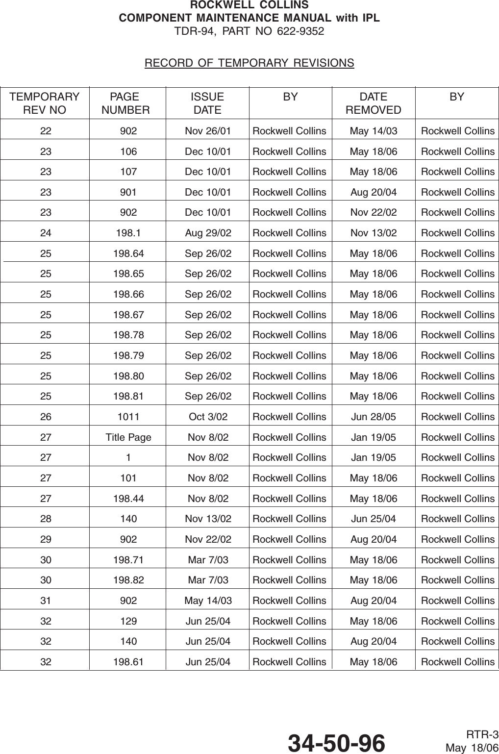
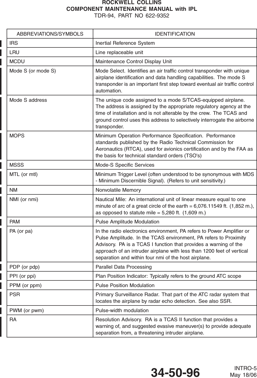
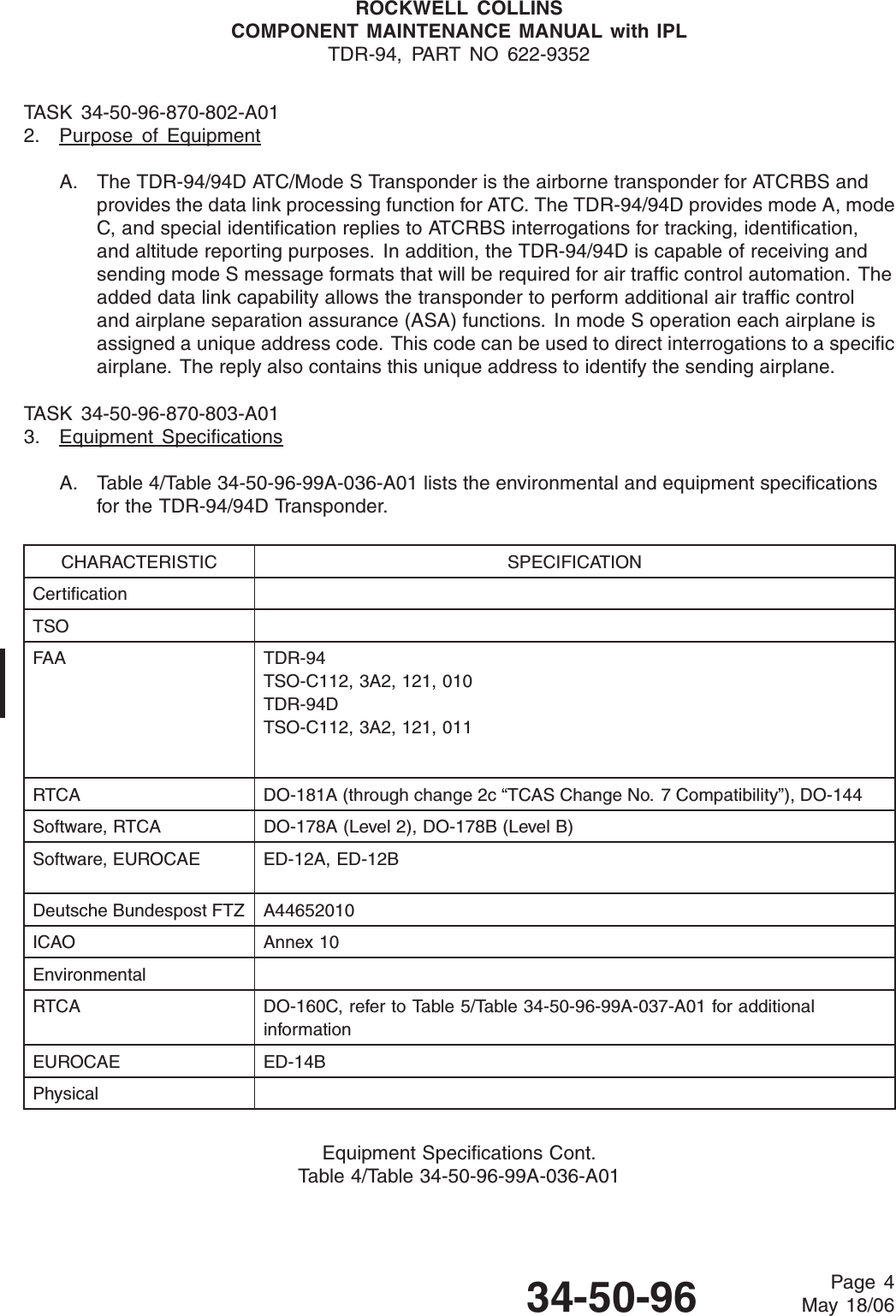
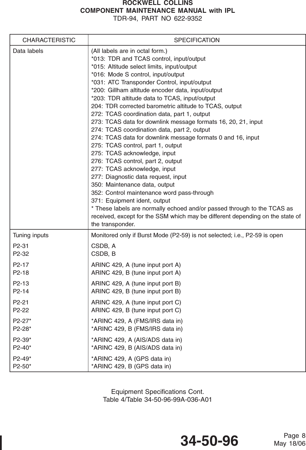
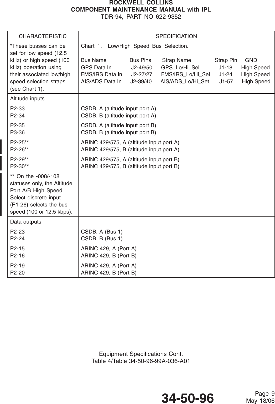
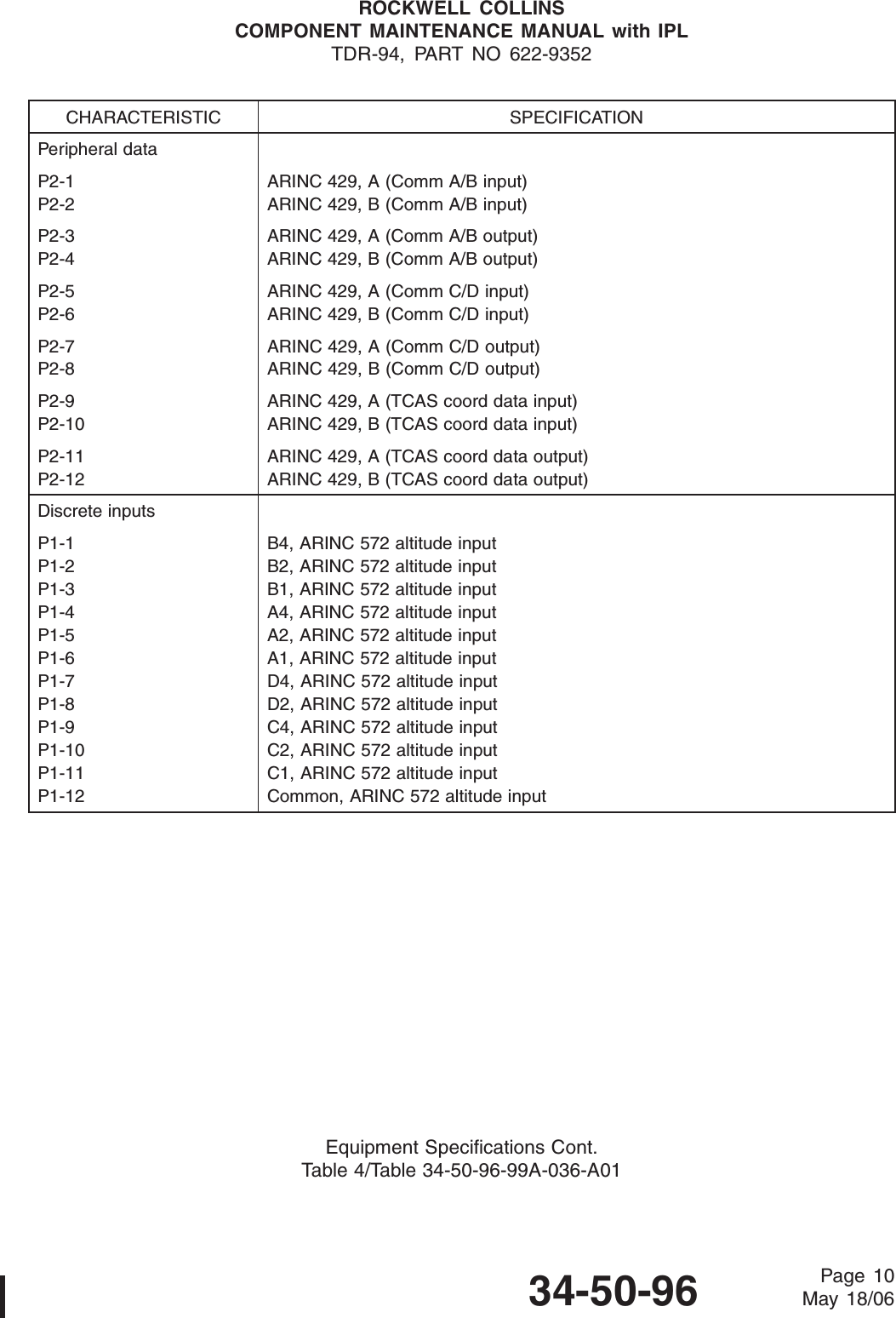
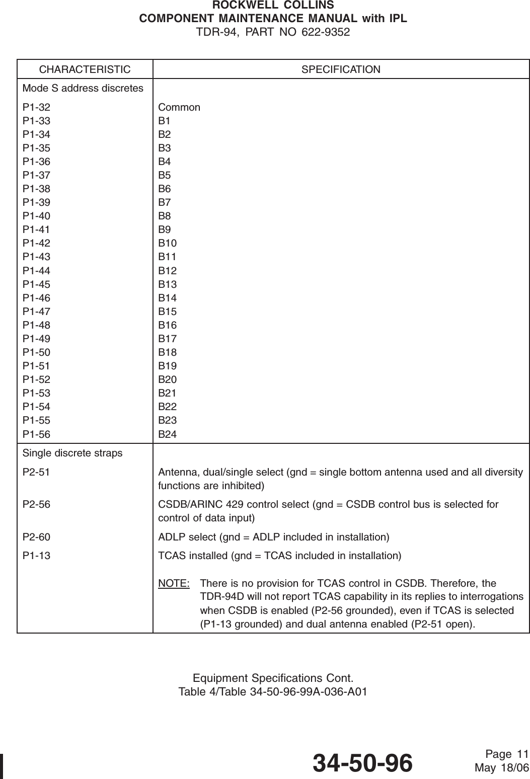
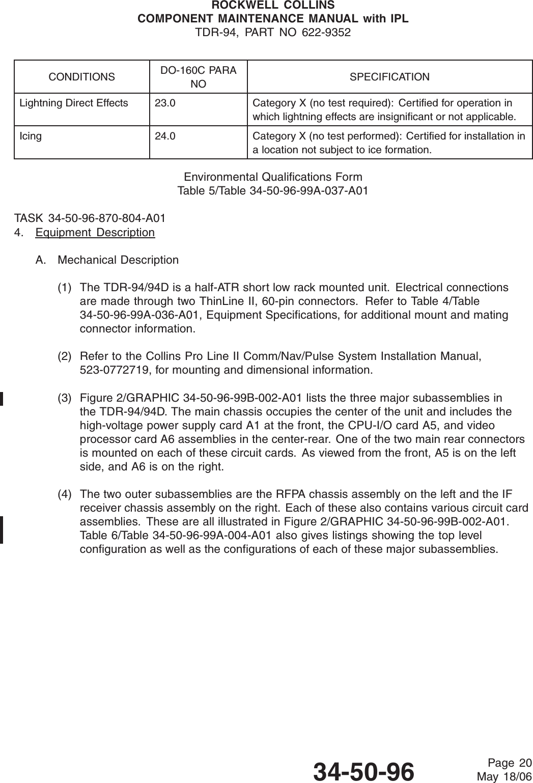
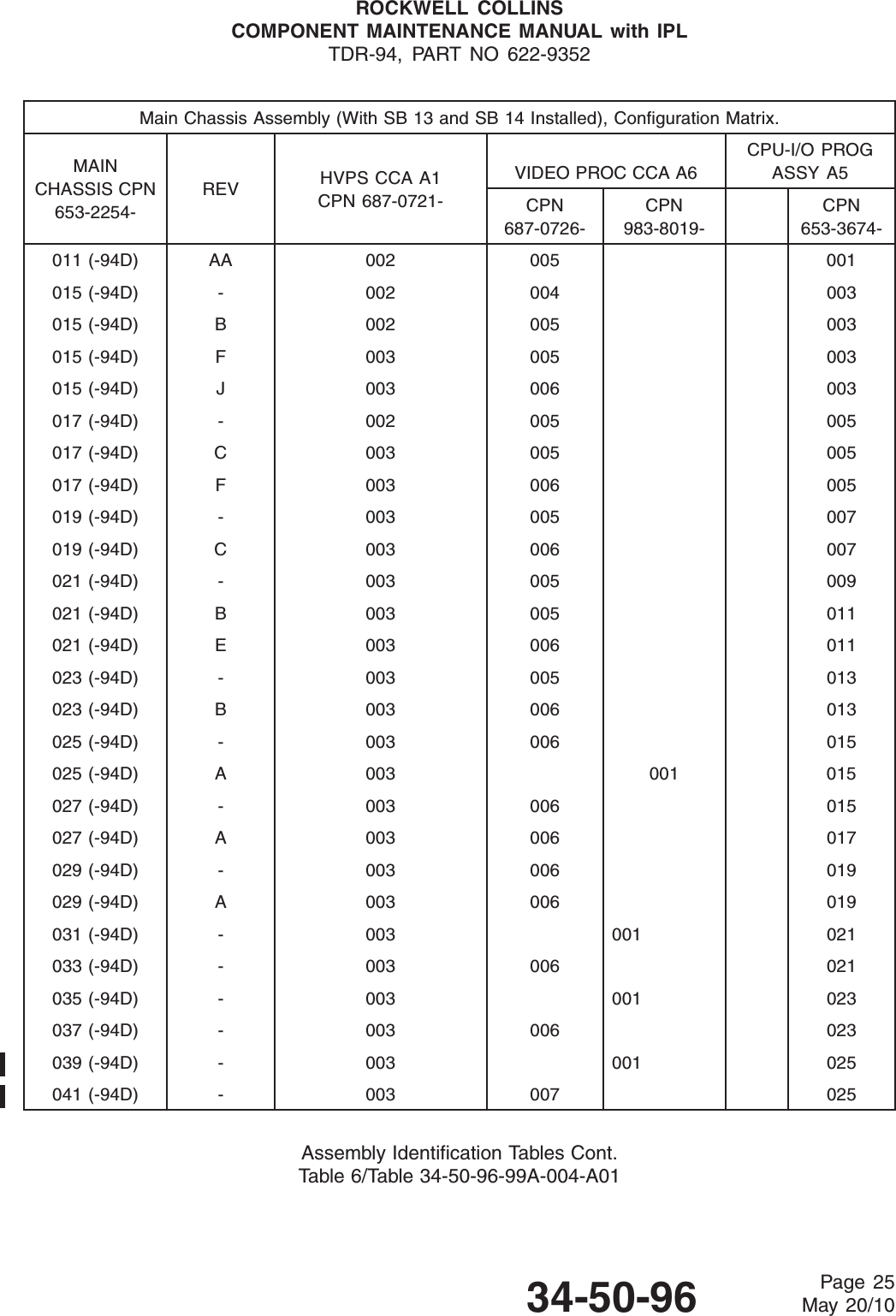
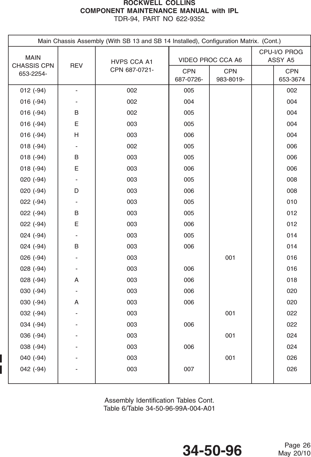
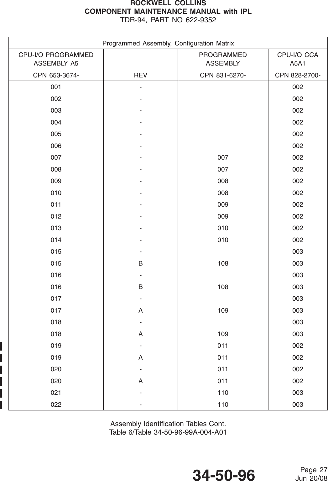
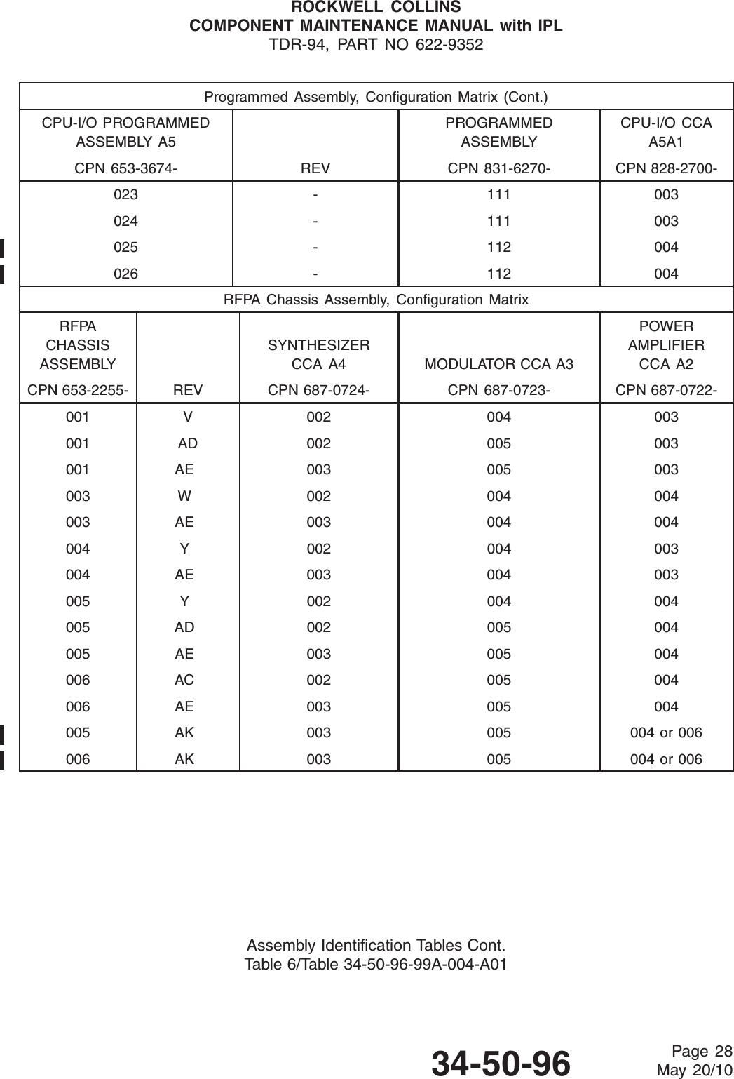
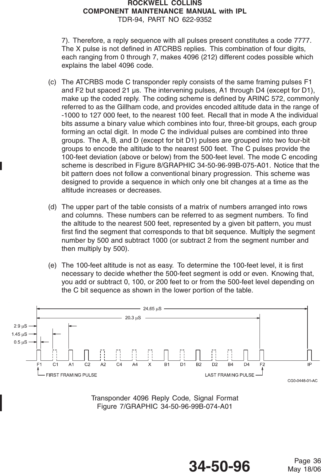
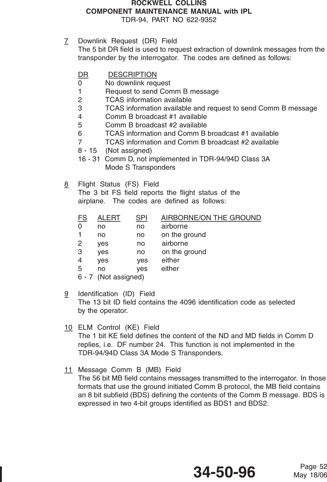


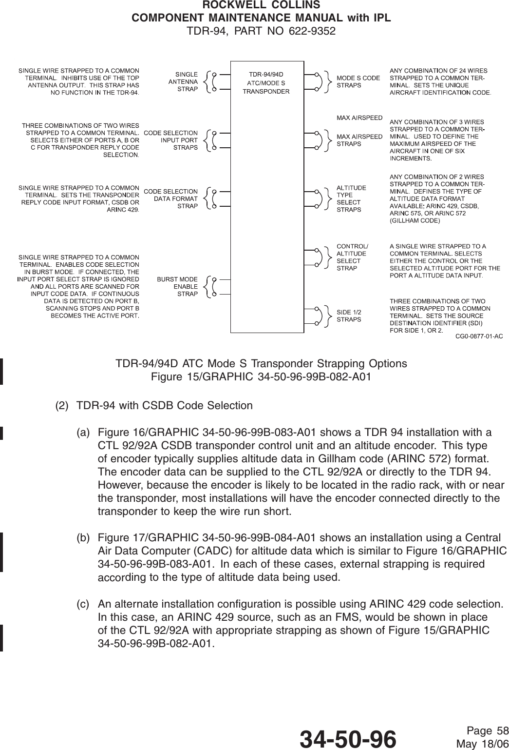
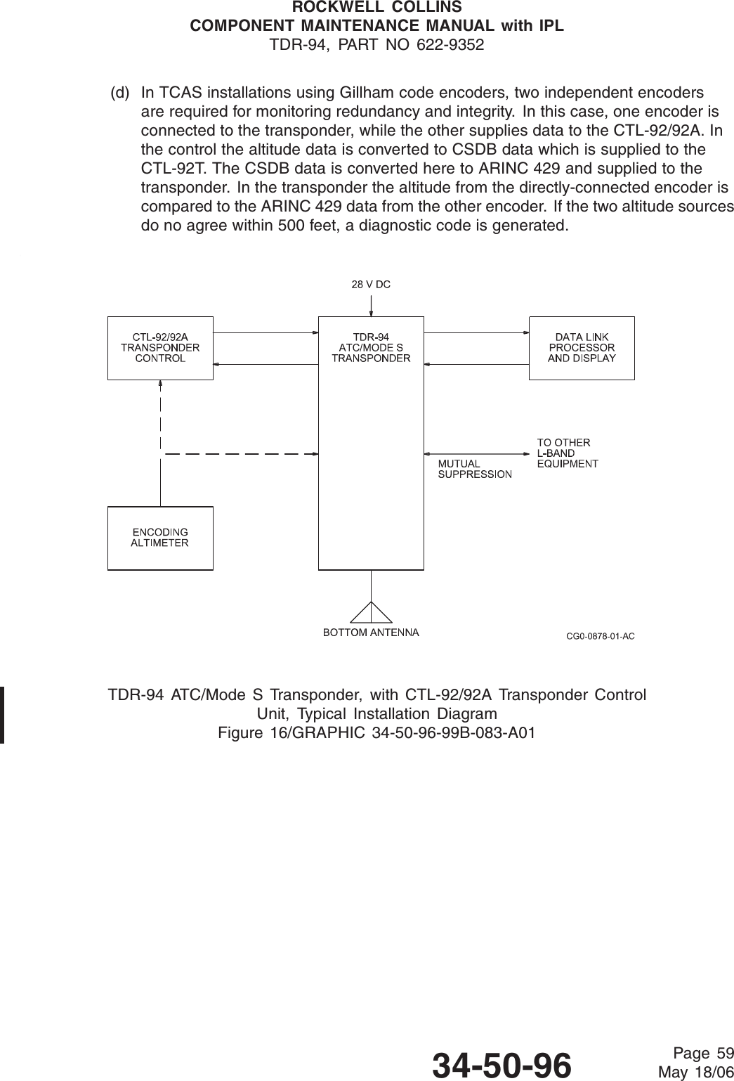
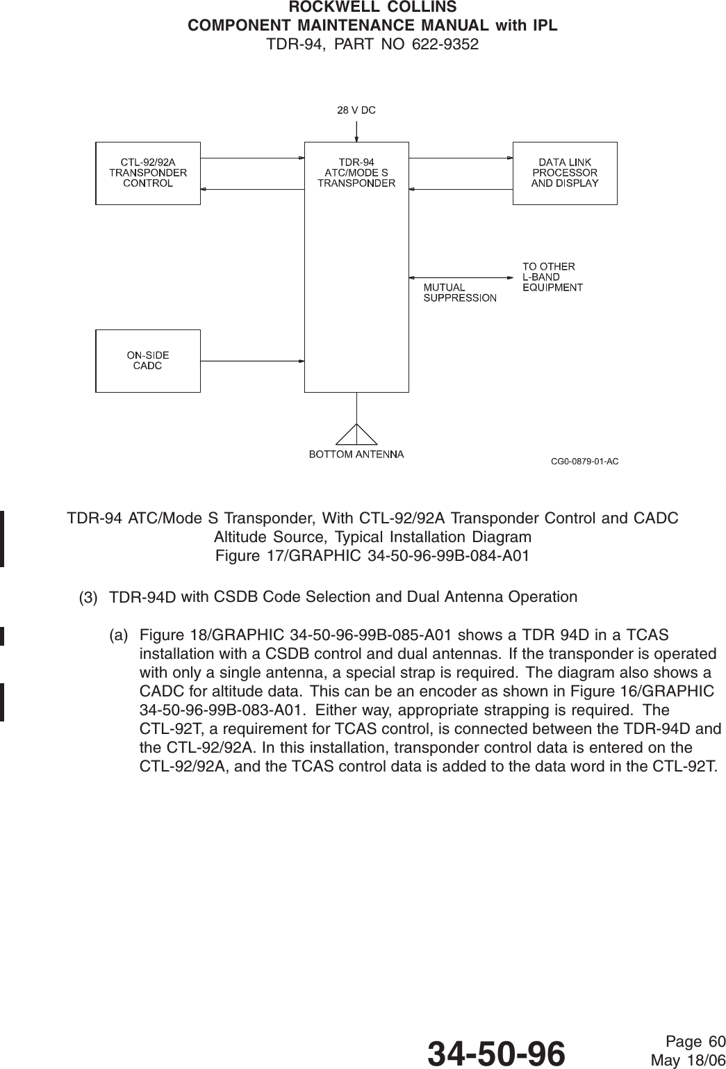
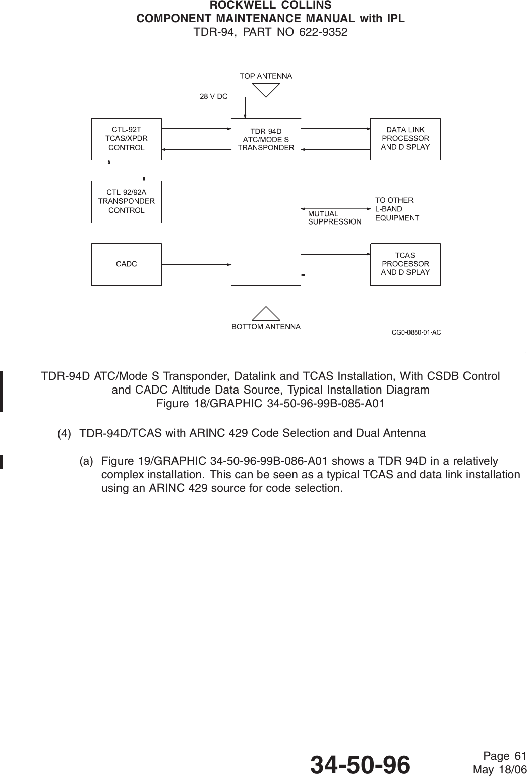
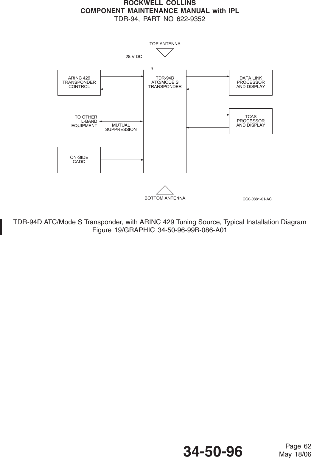
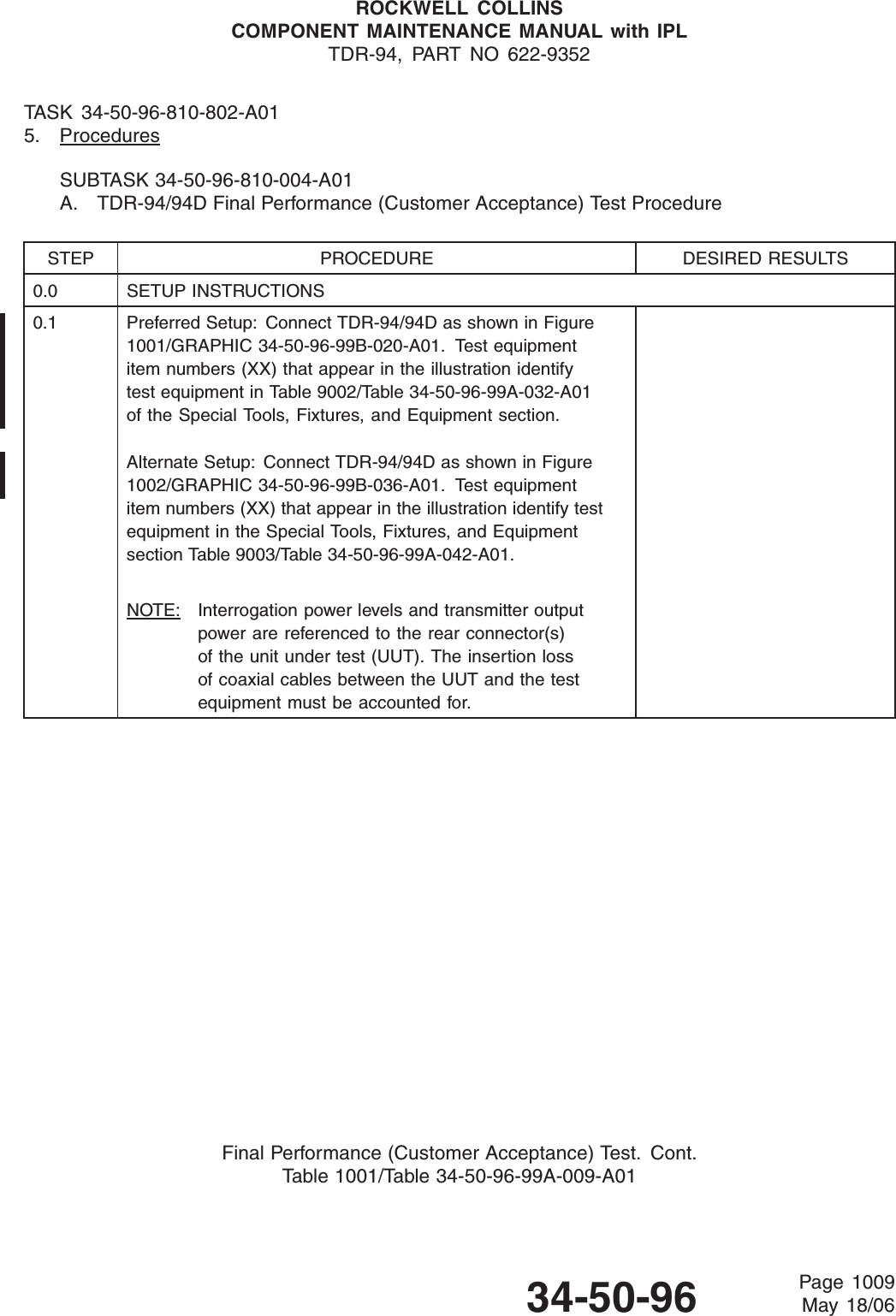
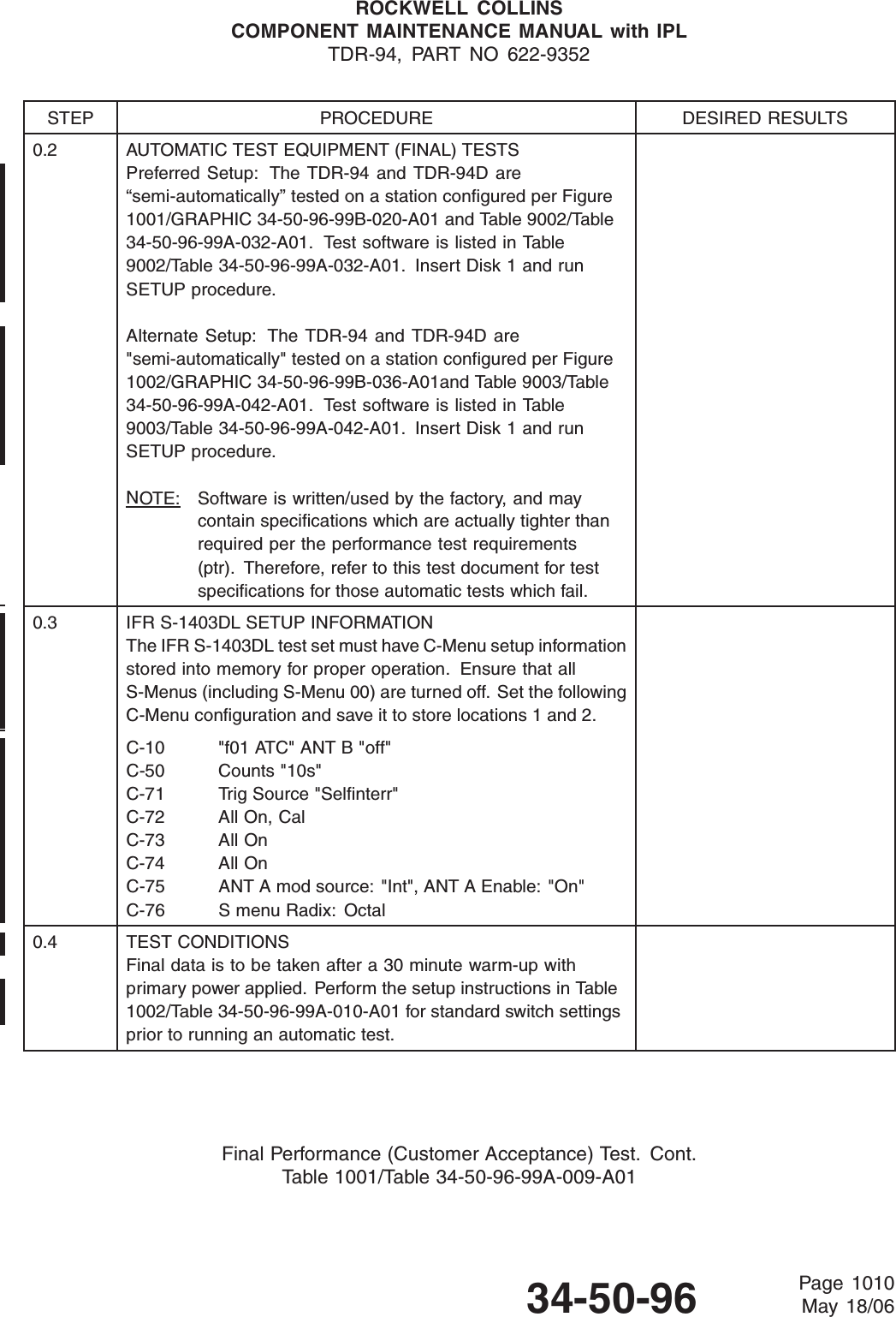
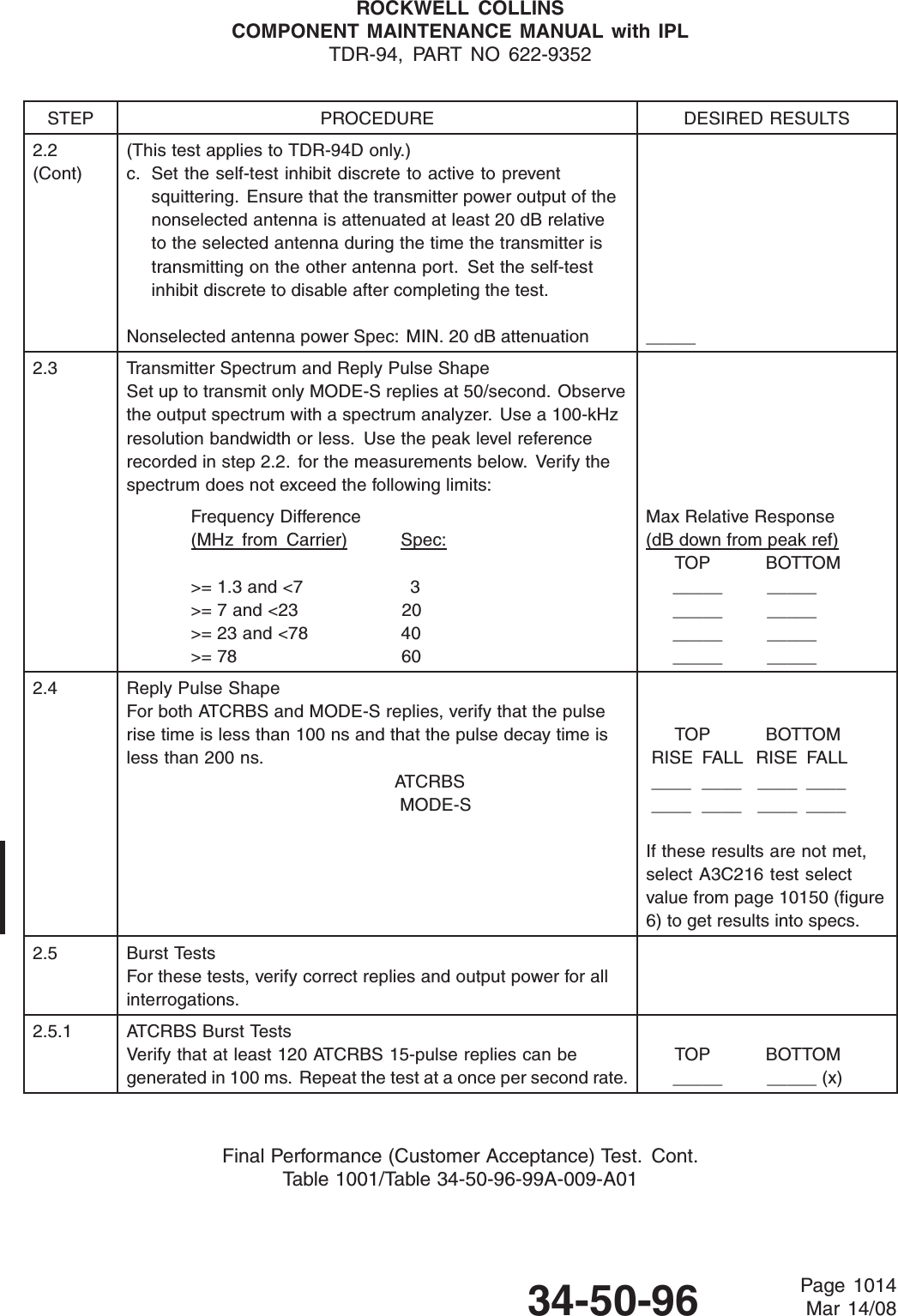
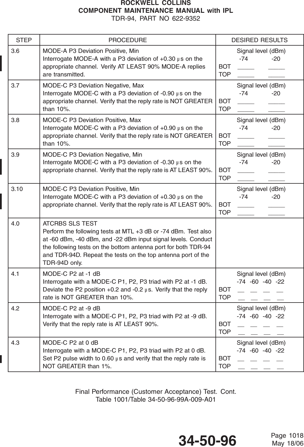
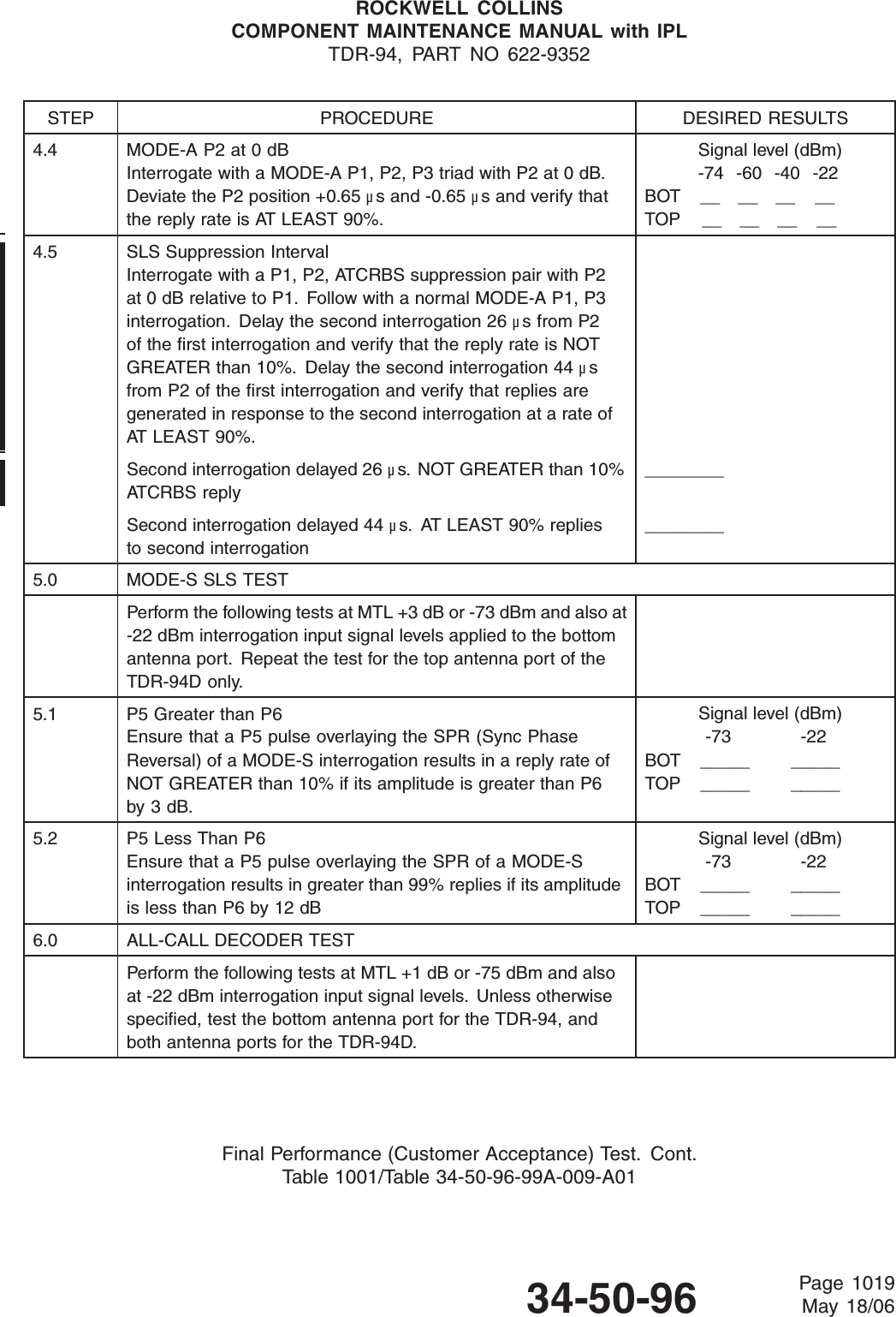
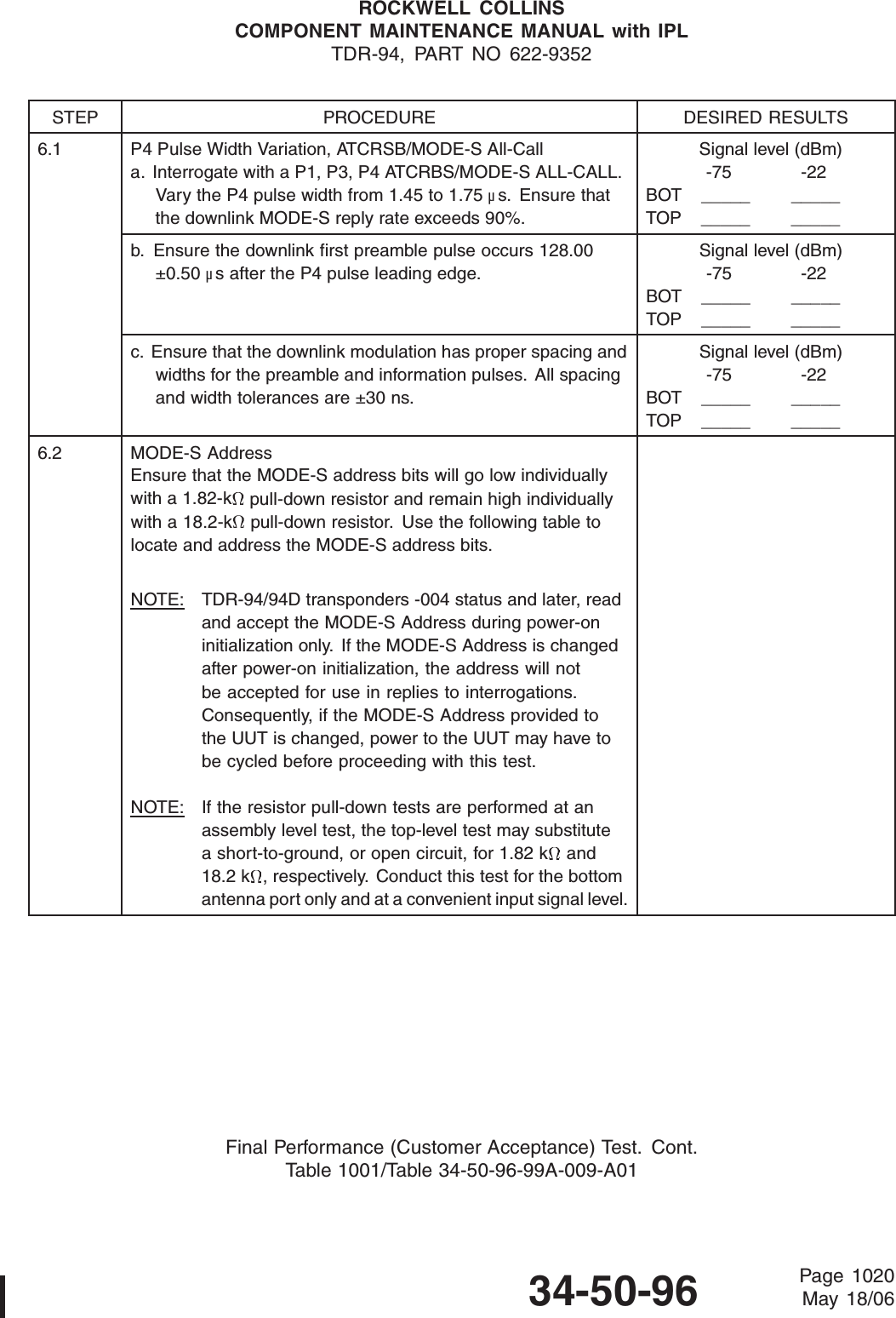
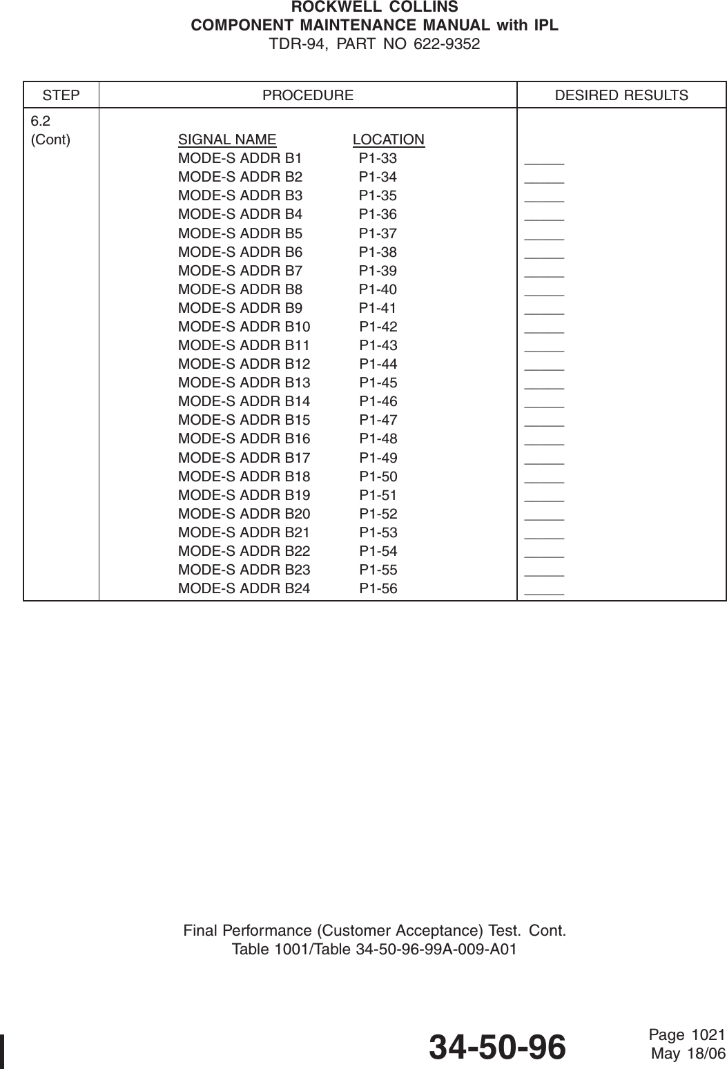
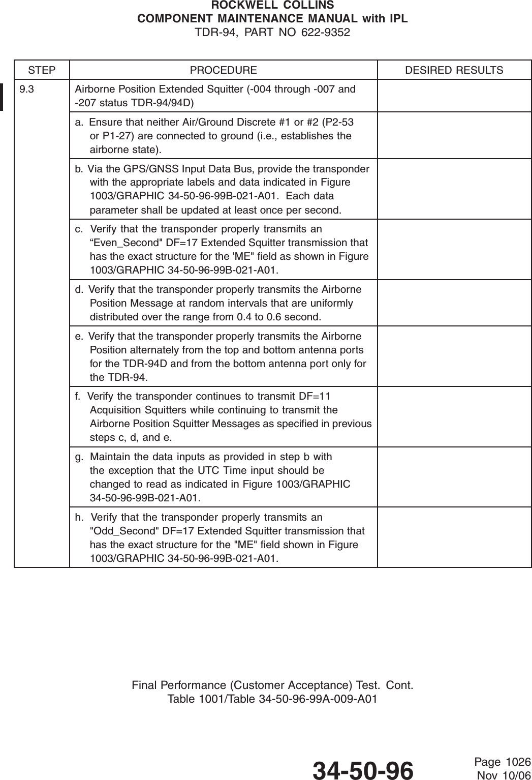
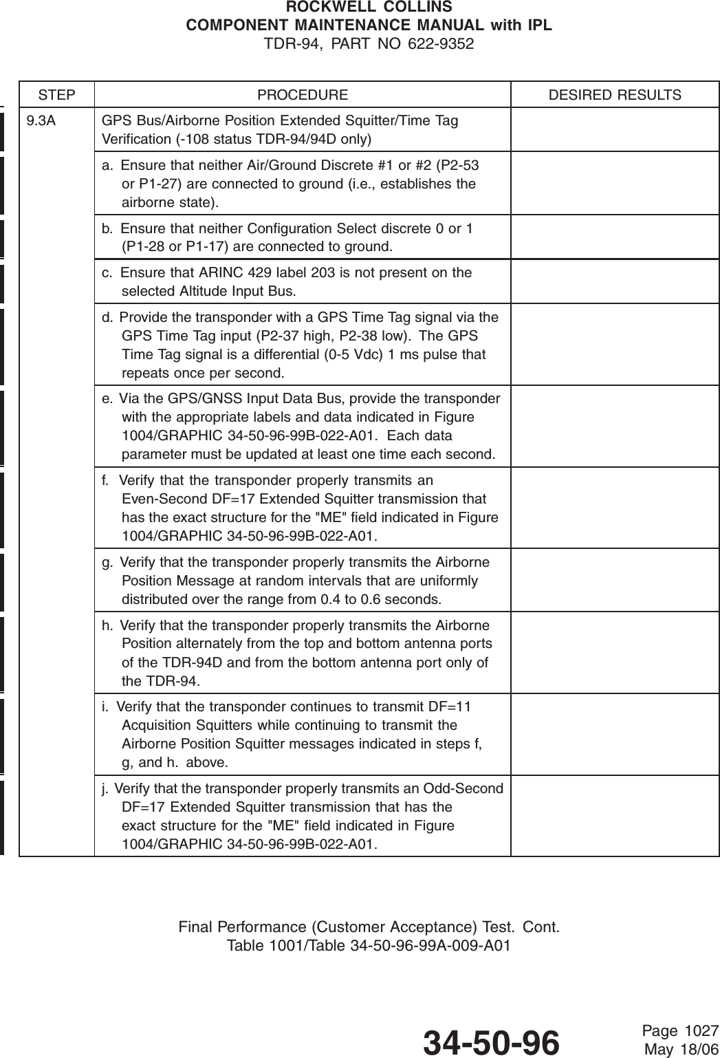
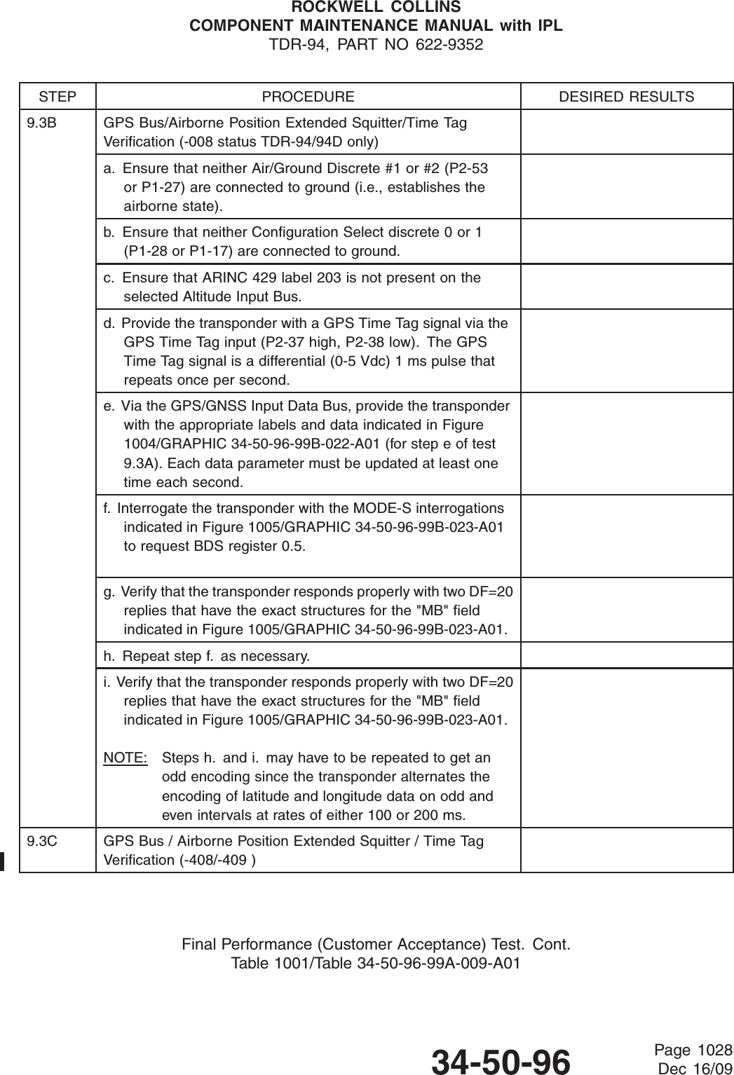
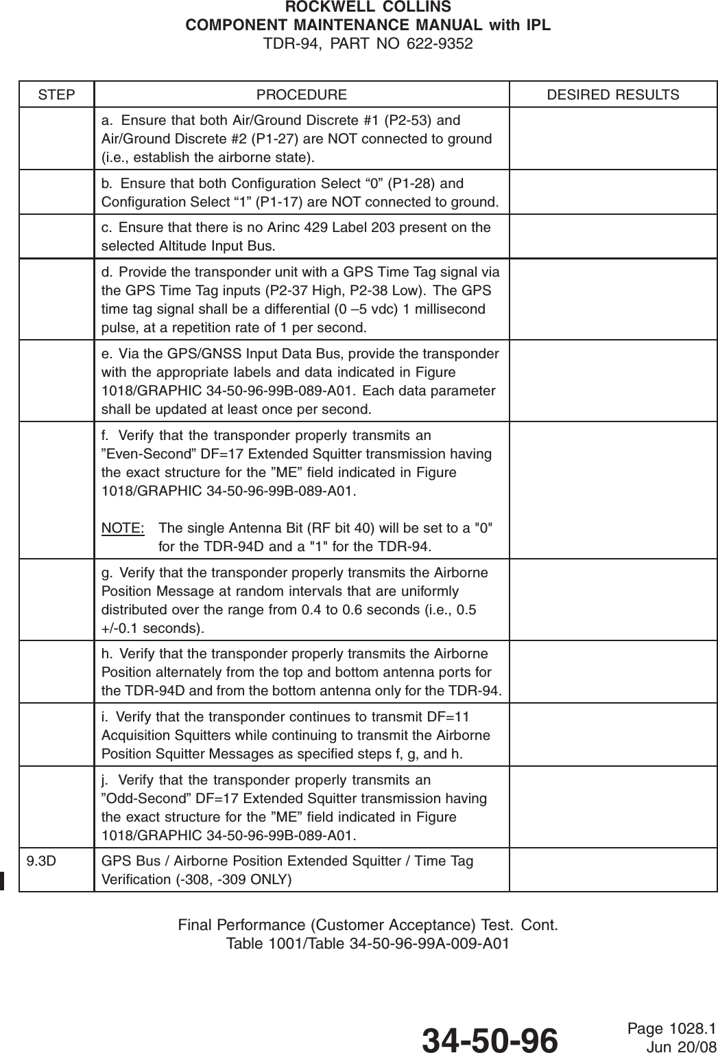
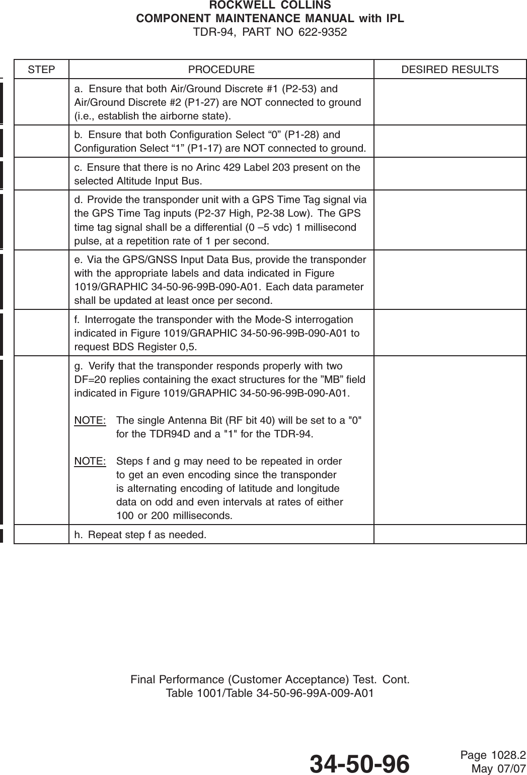
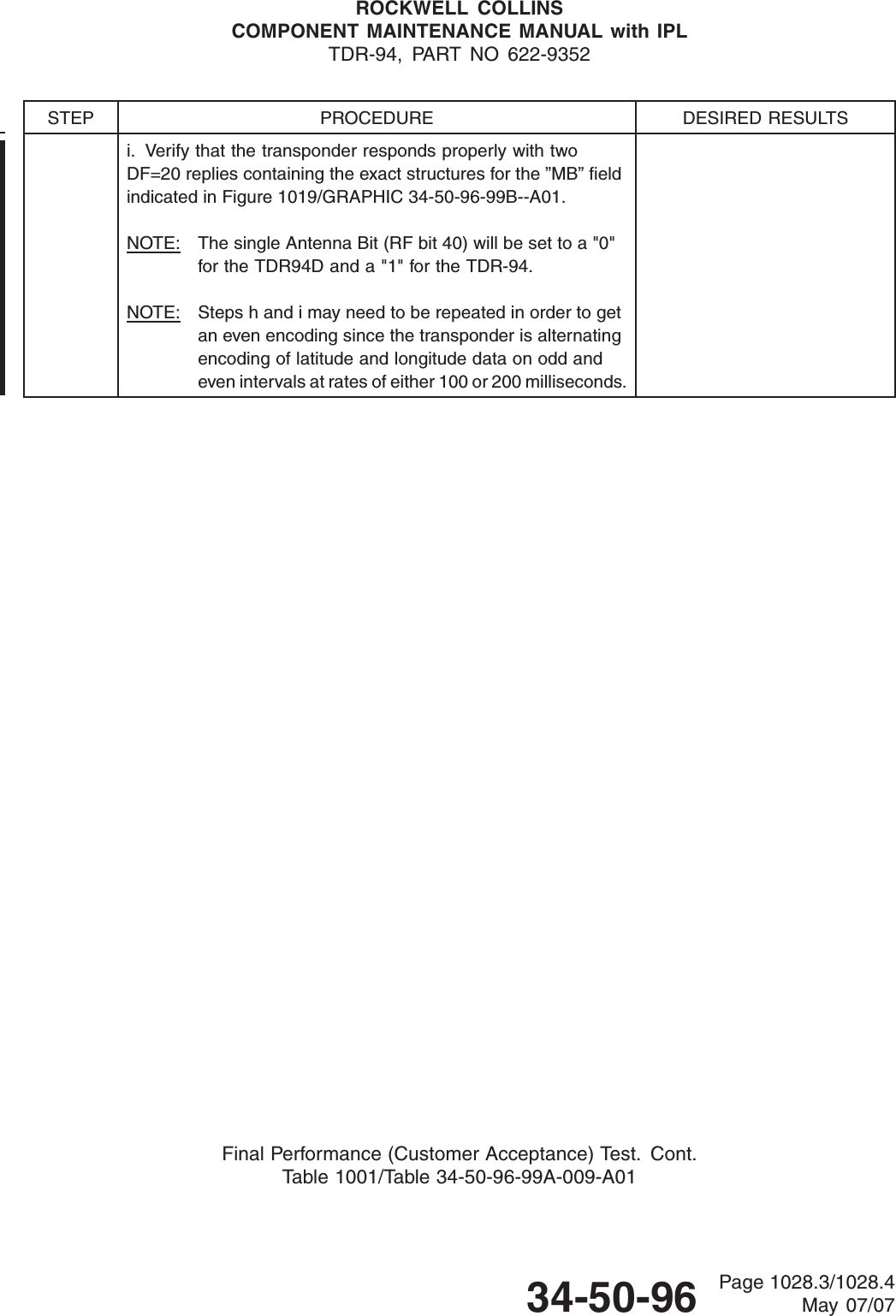
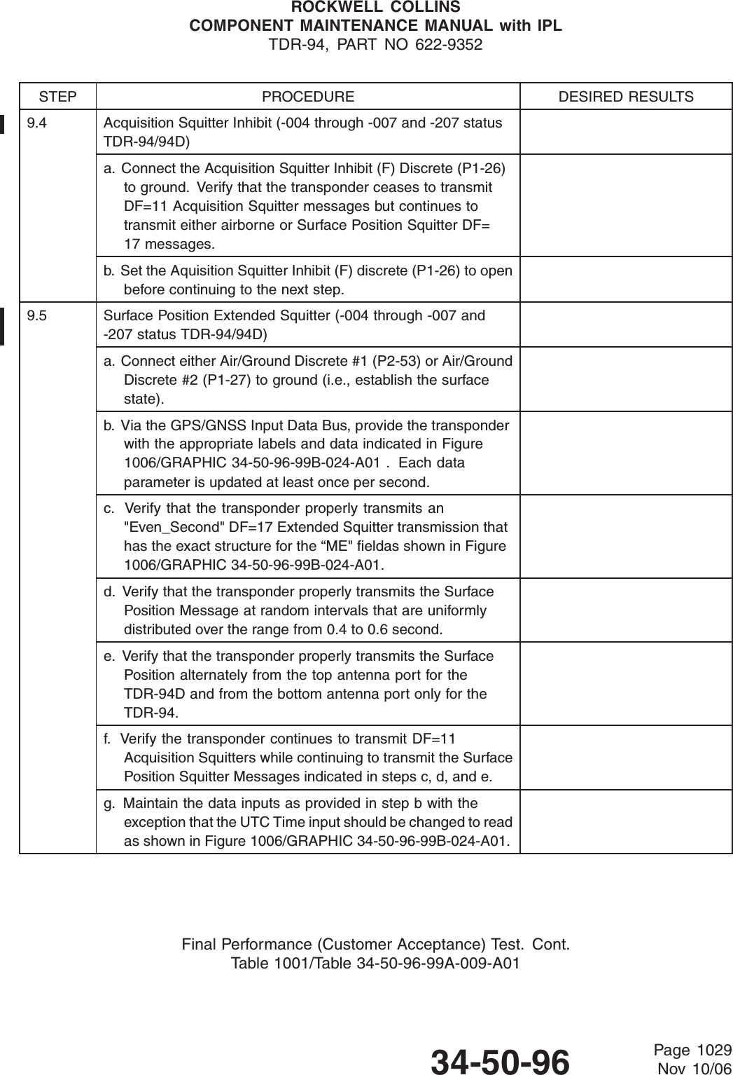
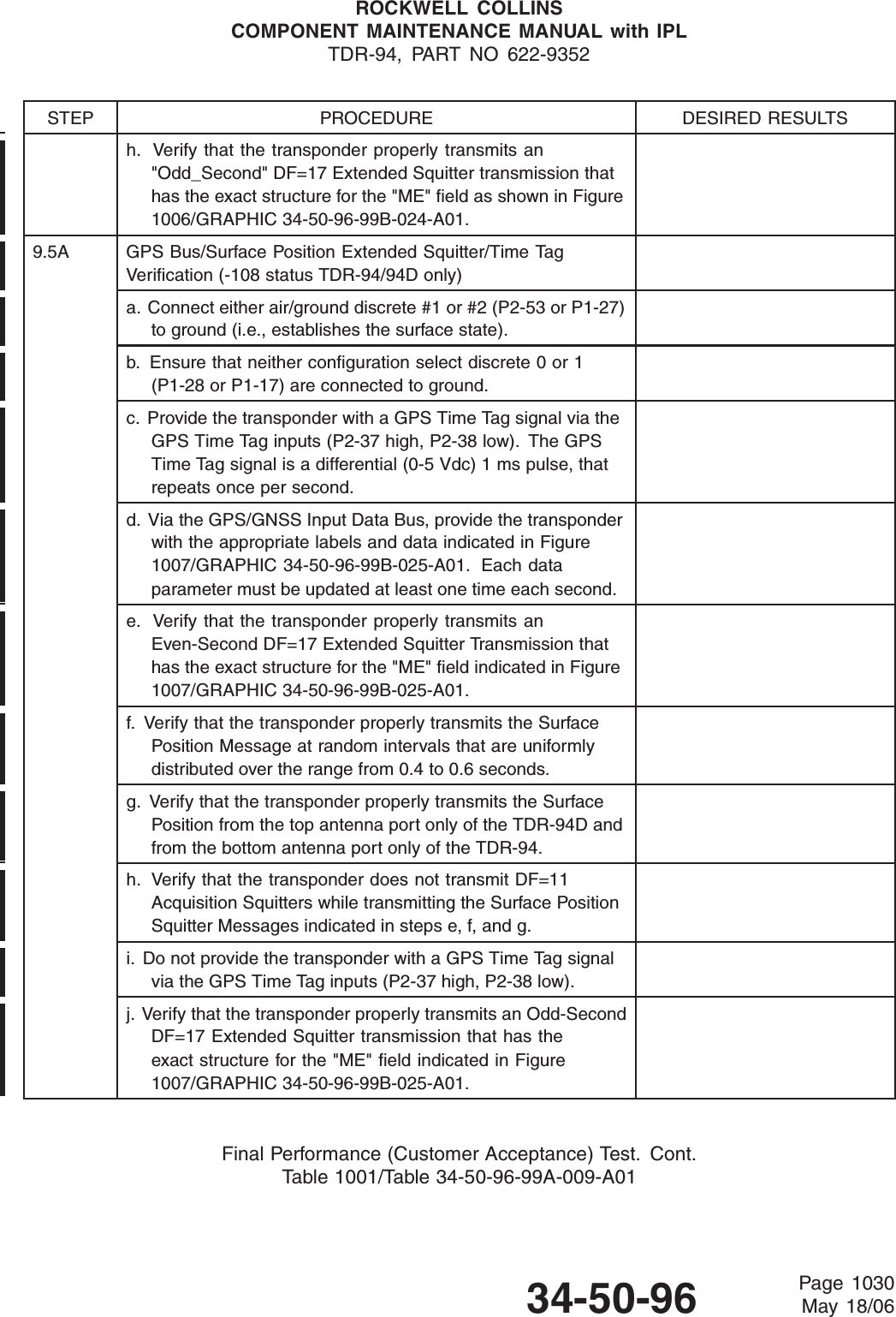
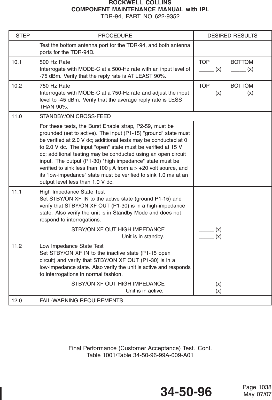
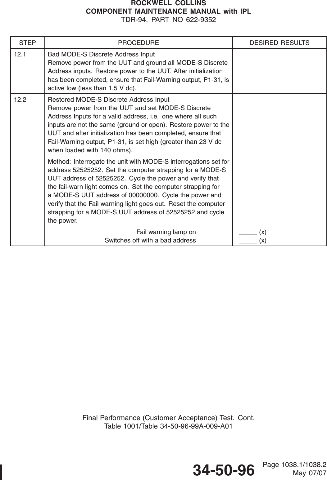
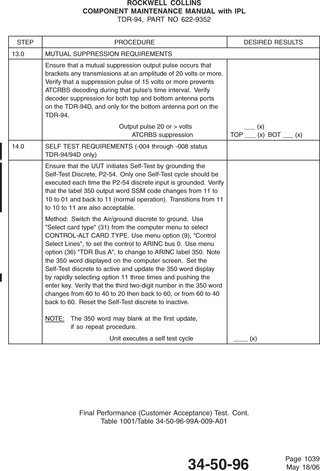
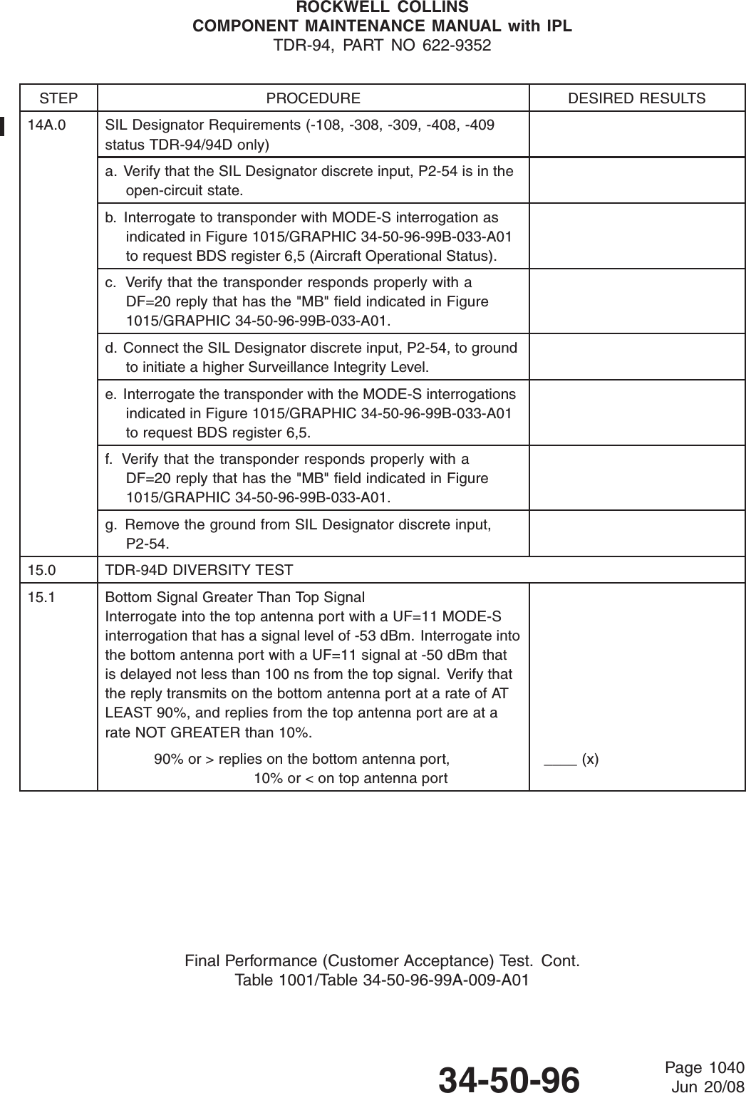
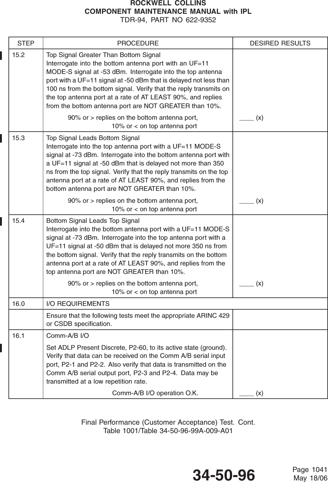
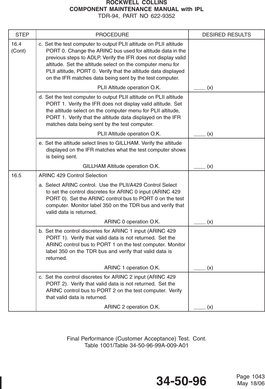
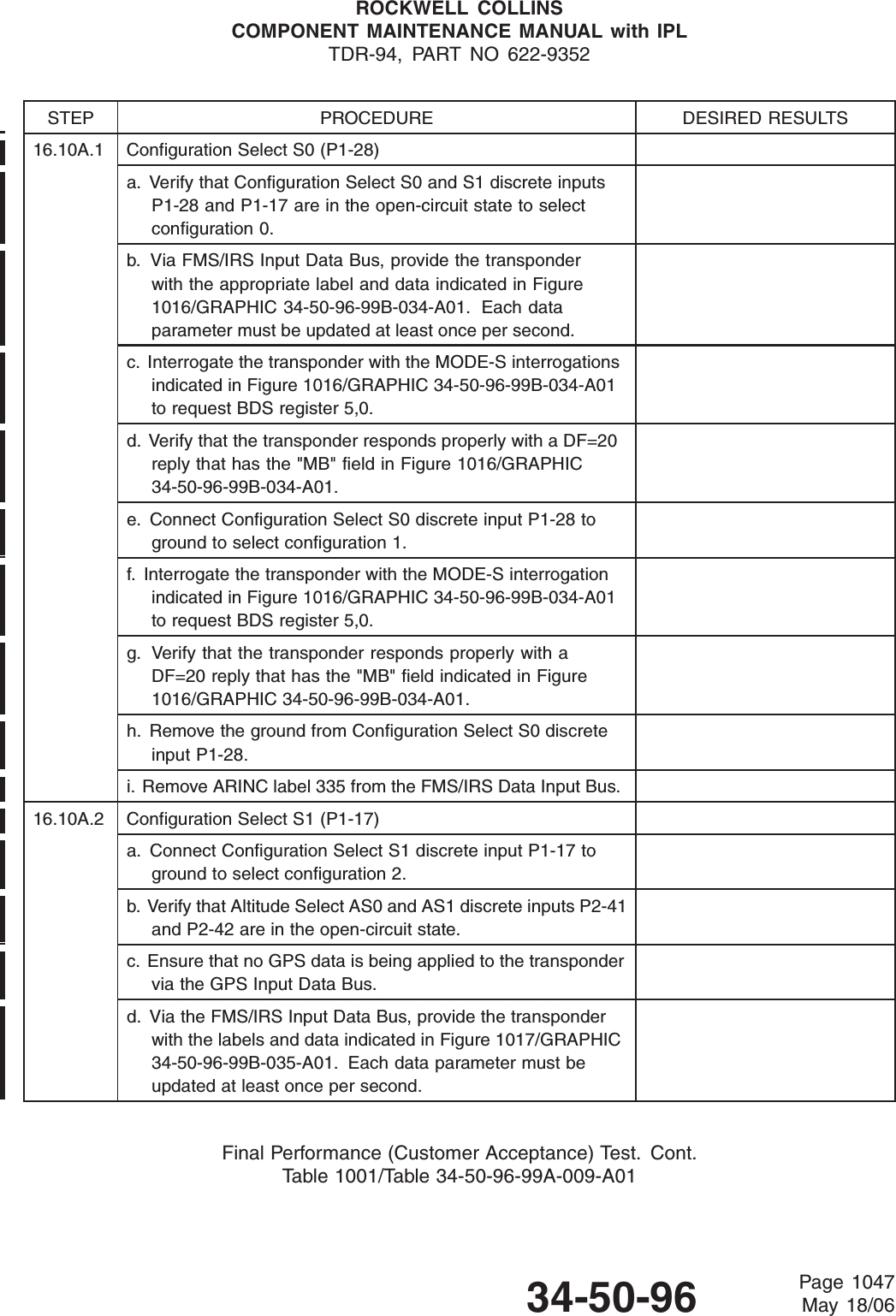
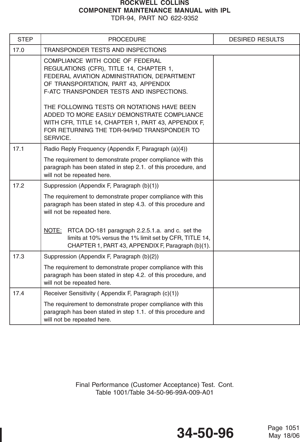
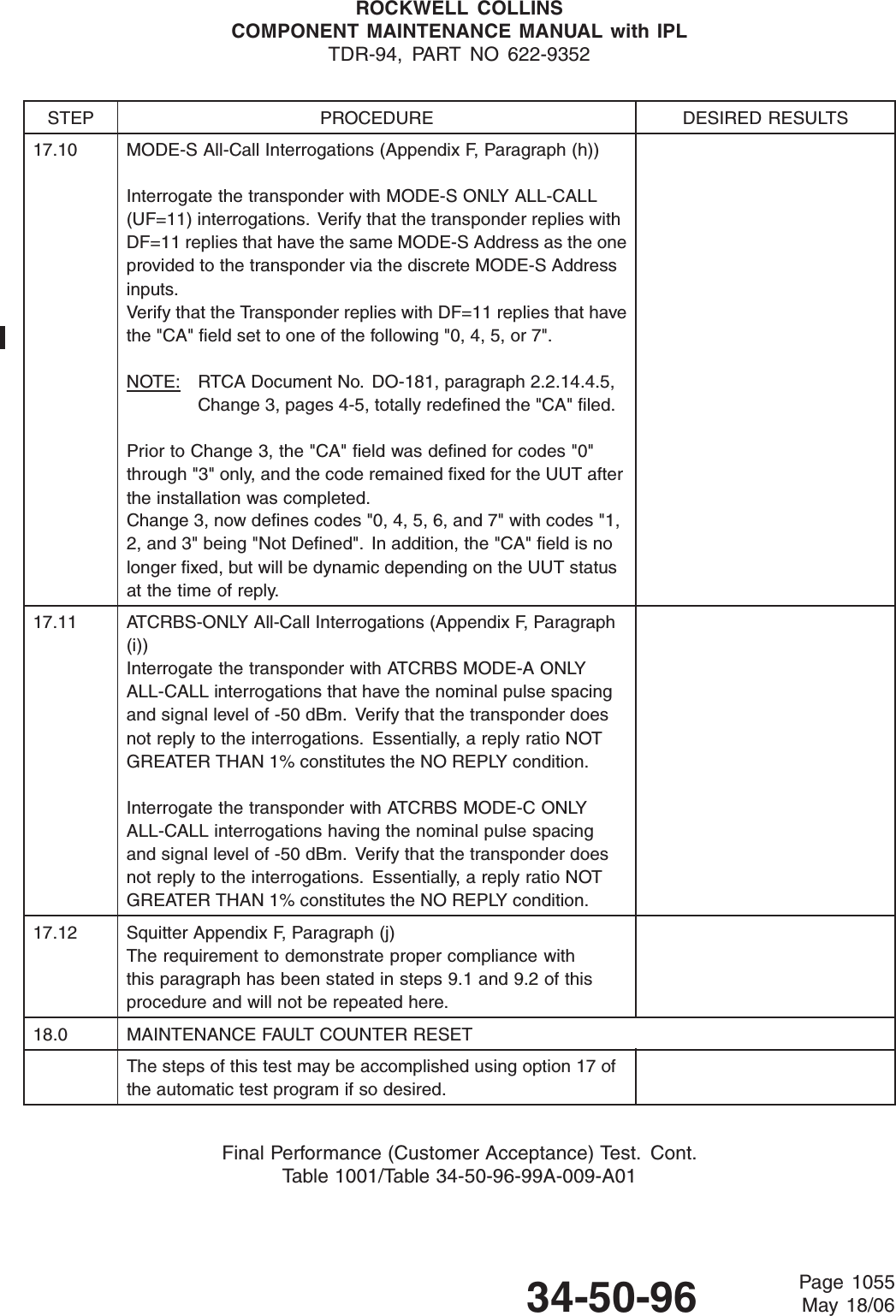
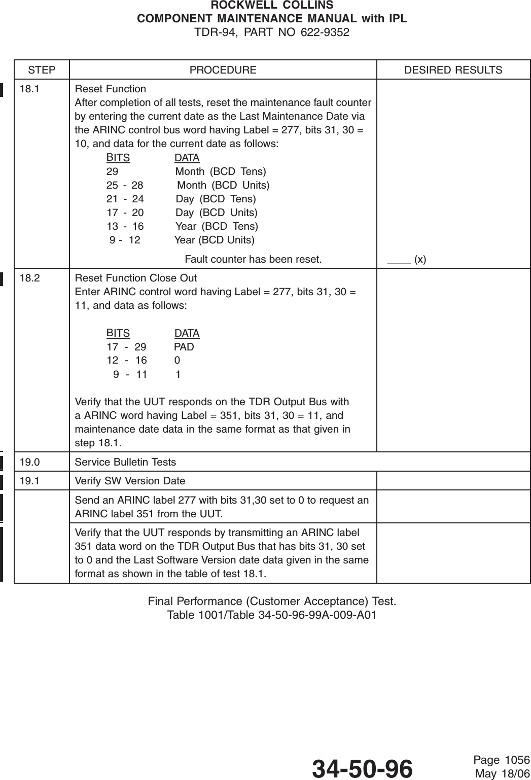
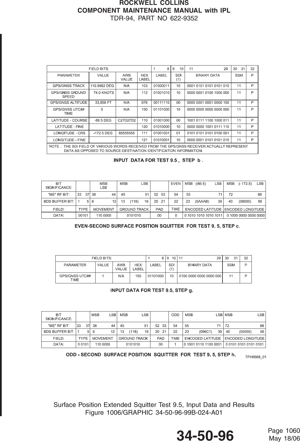
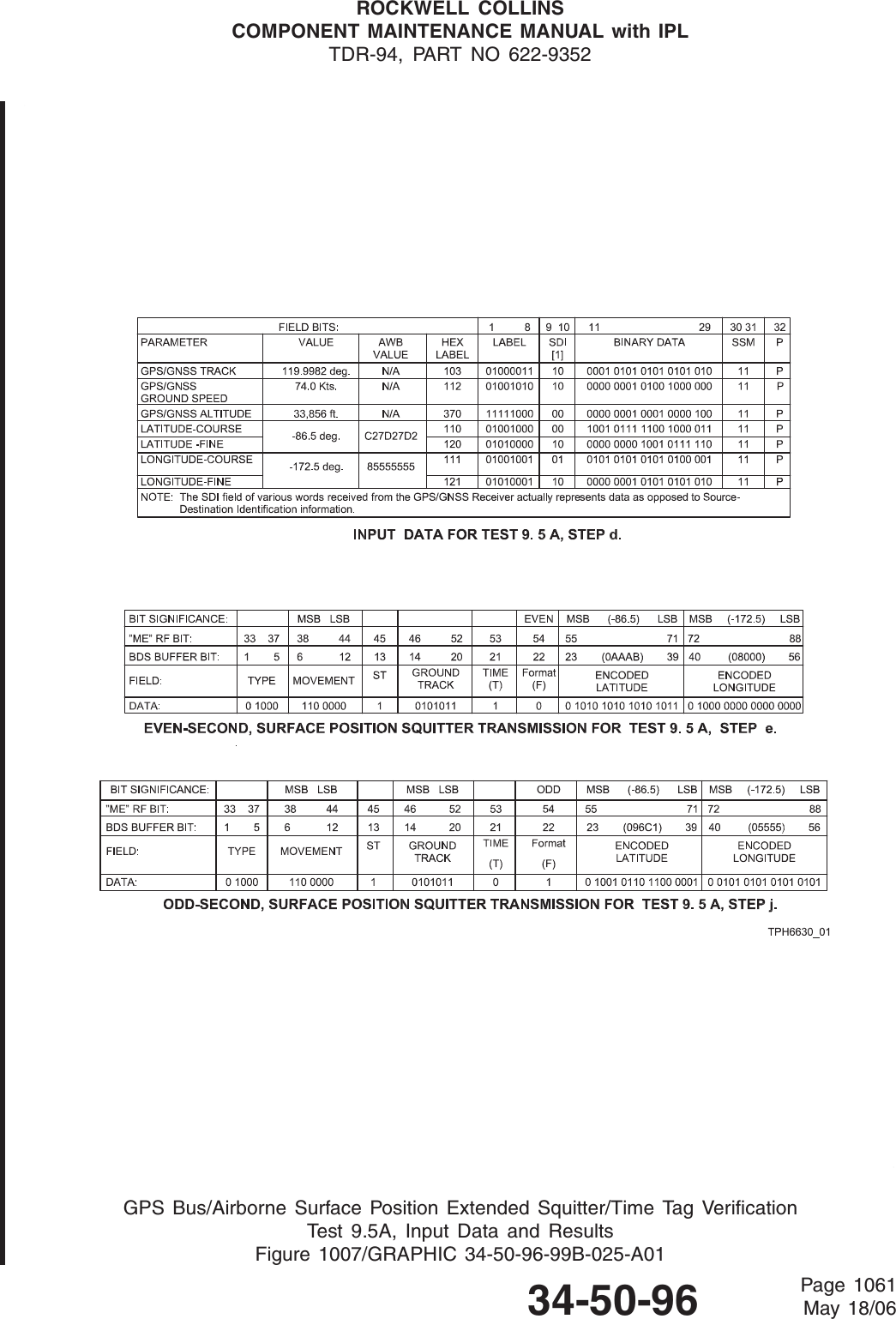
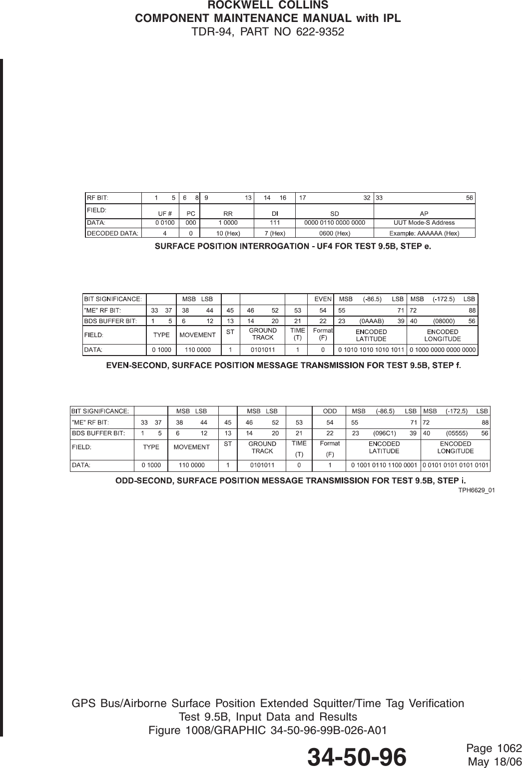
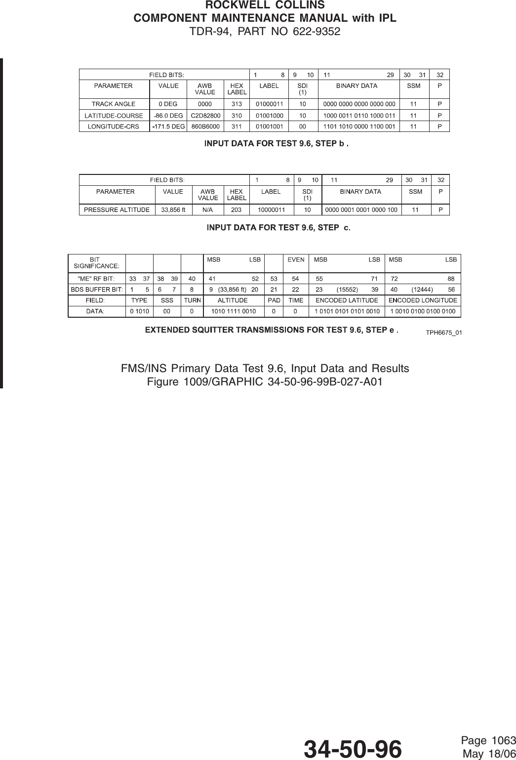
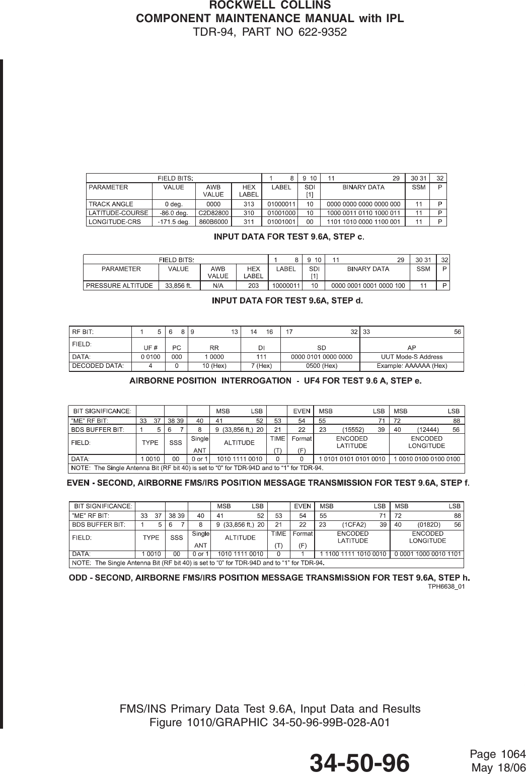
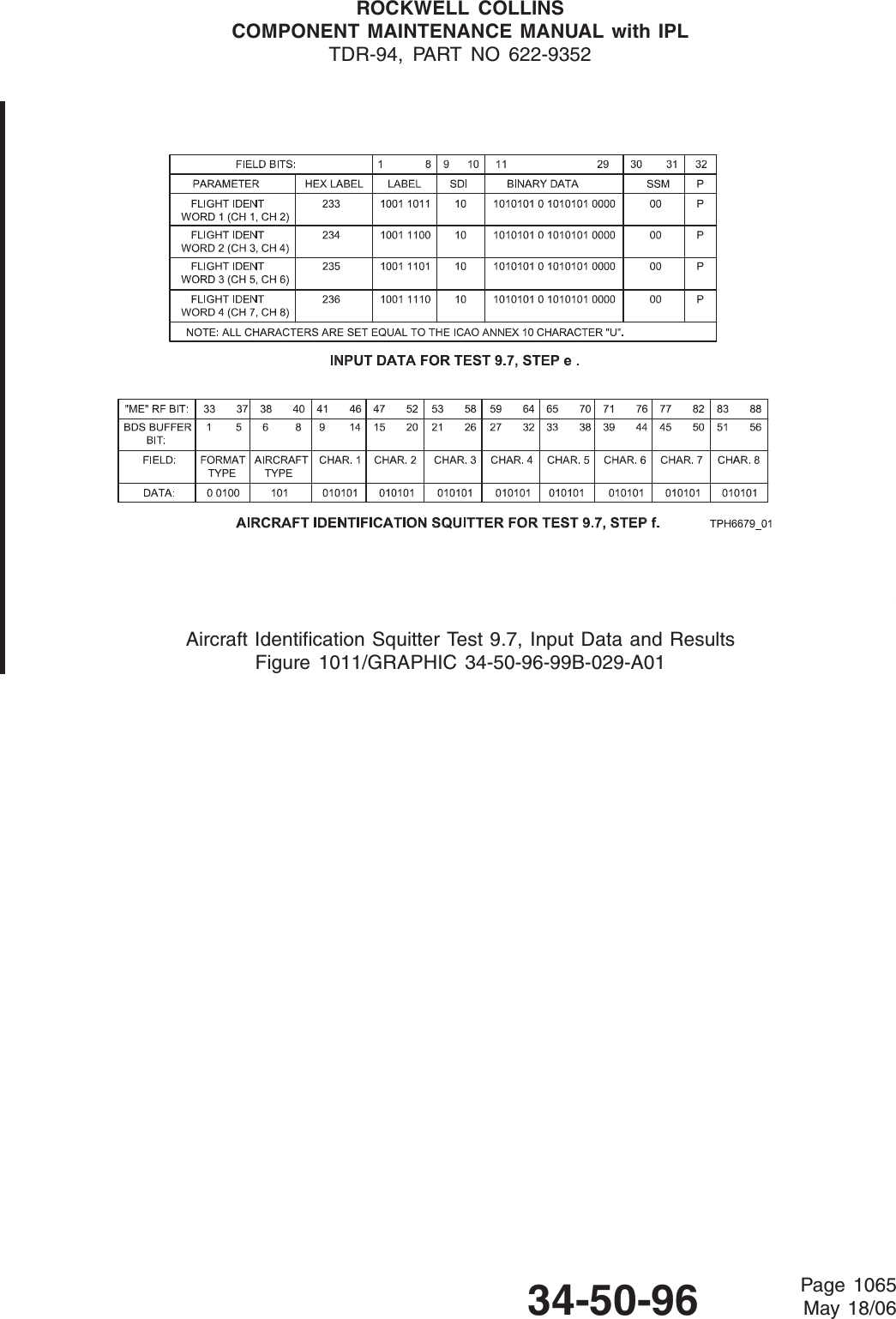
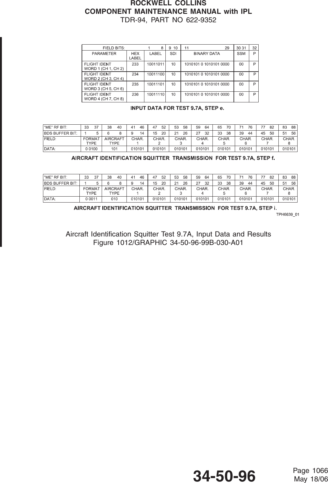
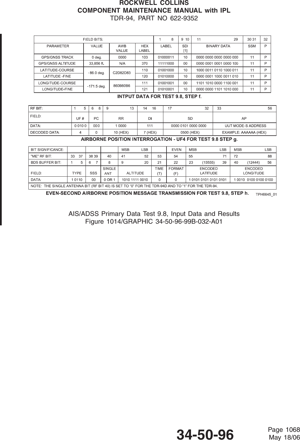
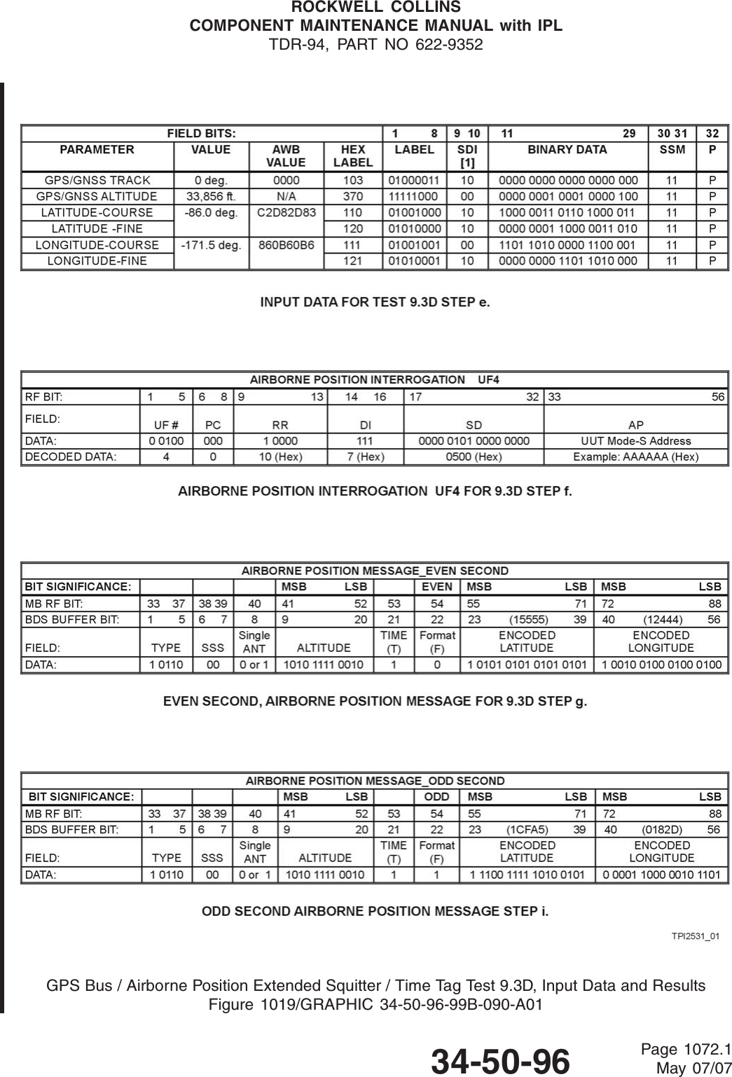
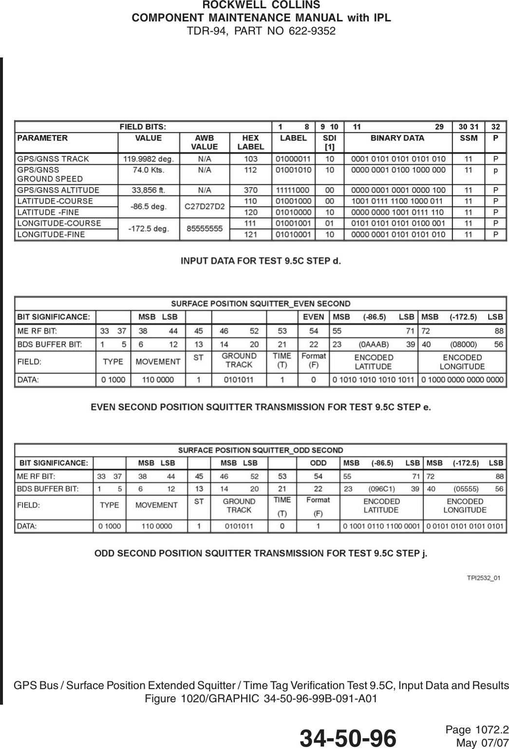
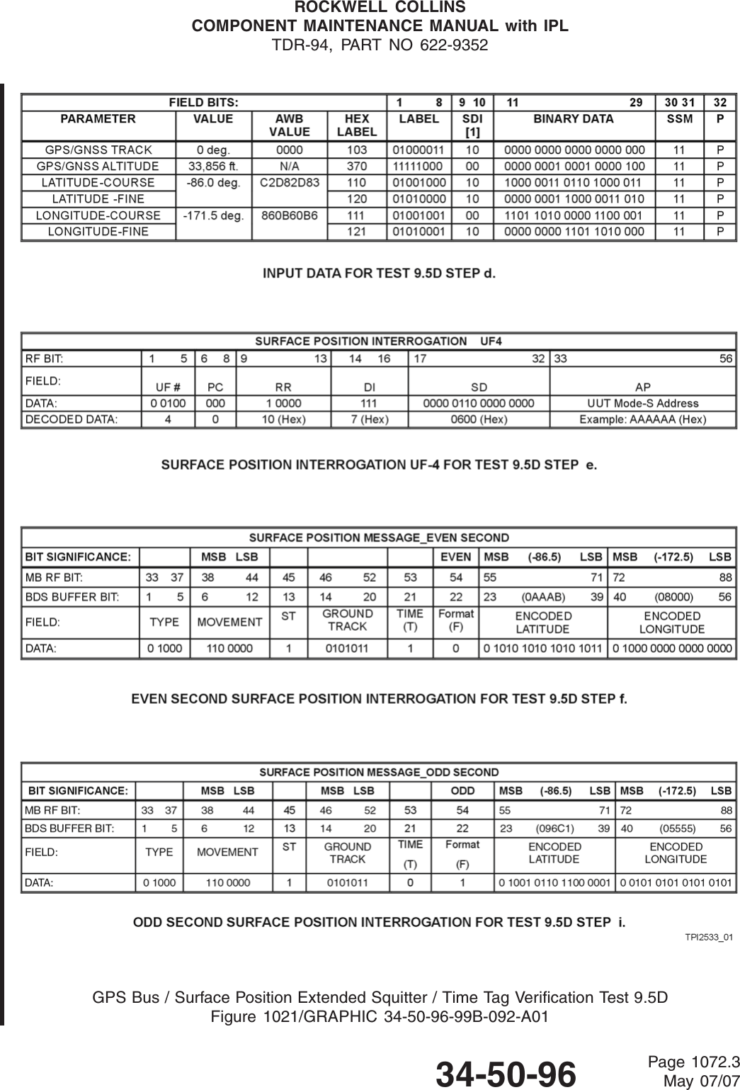
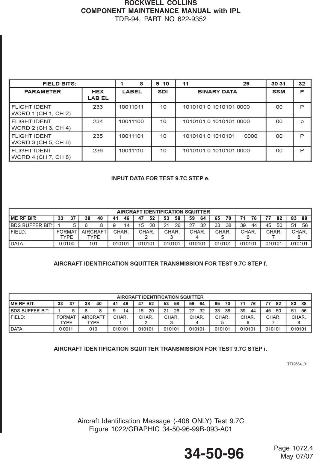
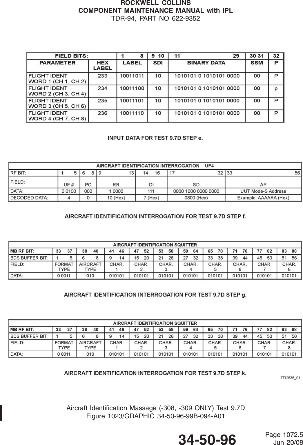
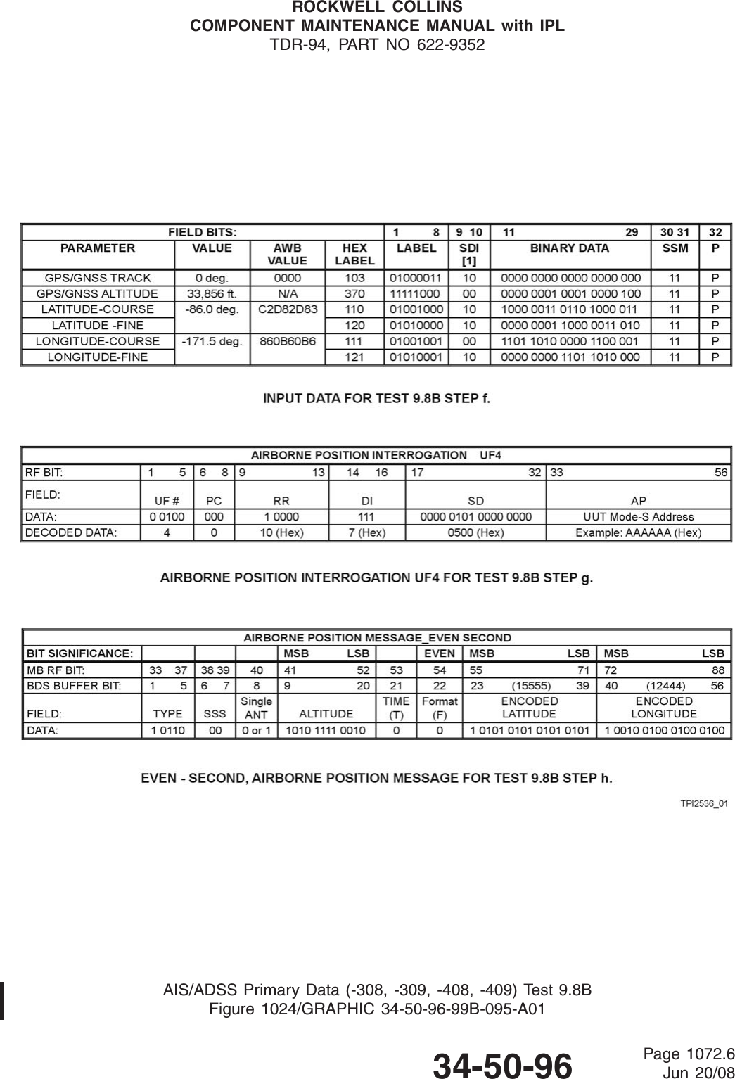
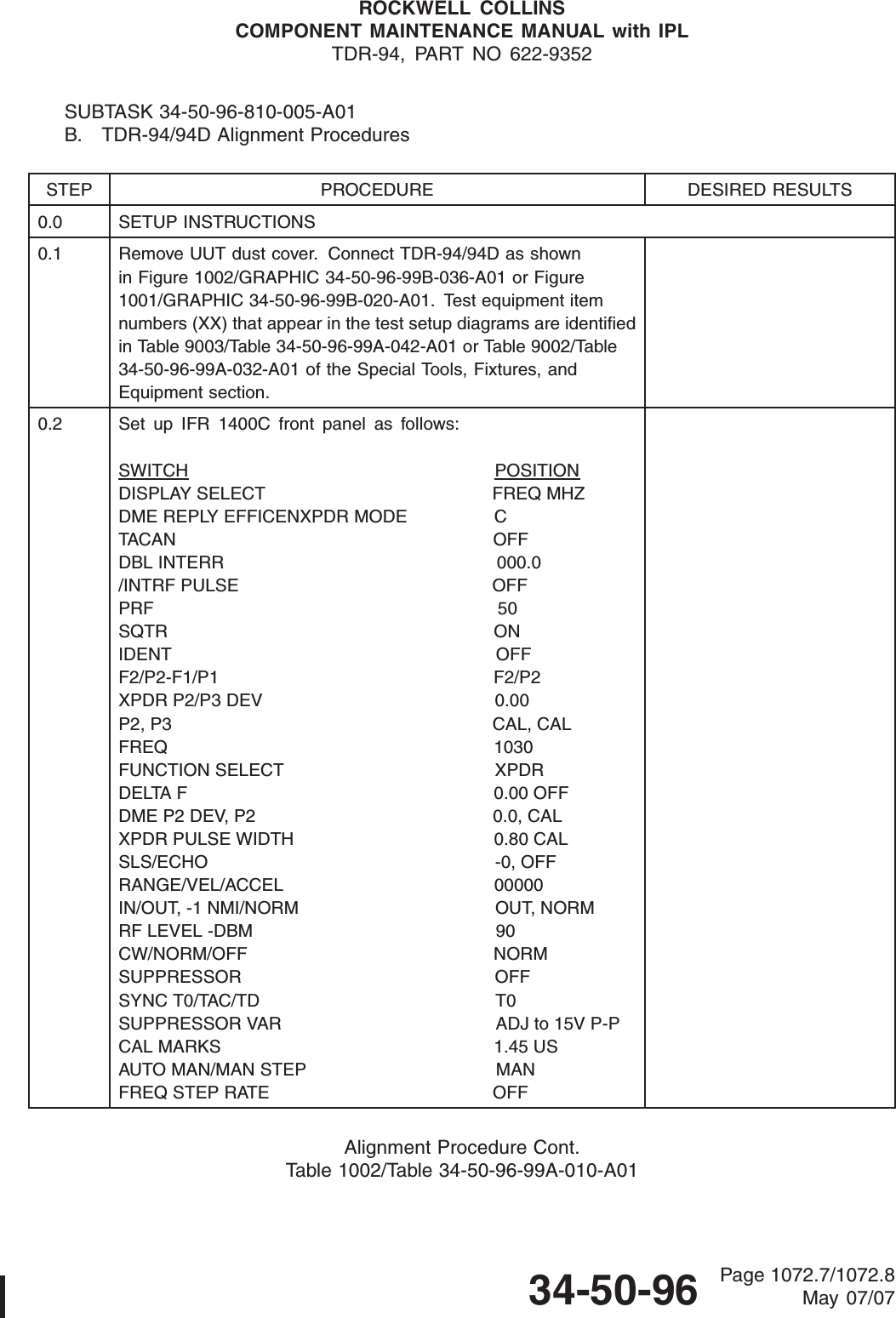
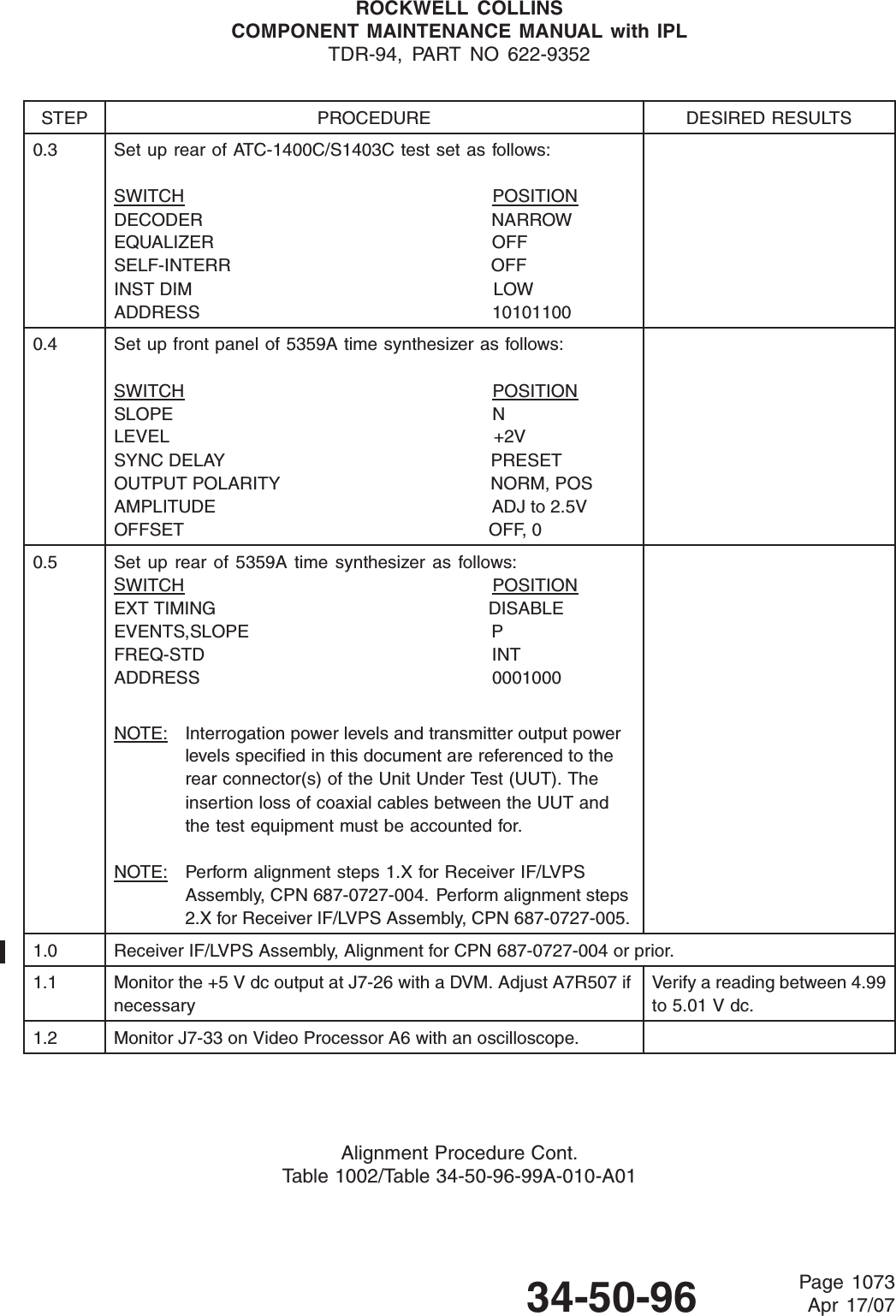
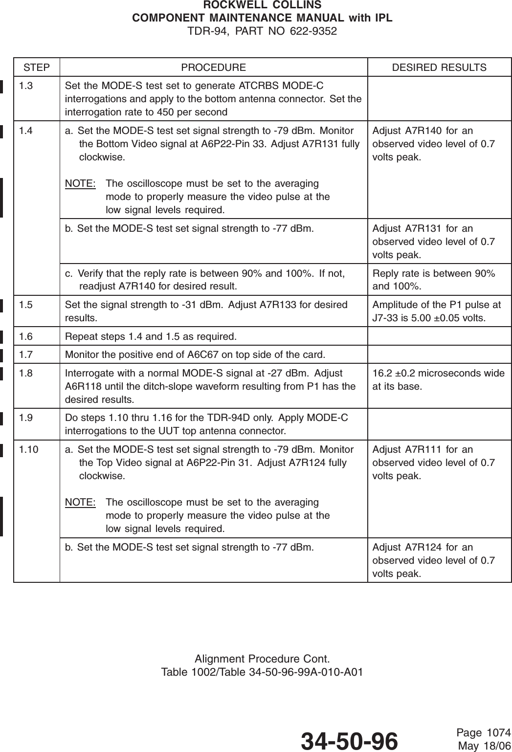
![ROCKWELL COLLINSCOMPONENT MAINTENANCE MANUAL with IPLTDR-94, PART NO 622-9352STEP PROCEDURE DESIRED RESULTS16.2 ADLP Present Discrete (P2-60)Verify that when this discrete is ground, the Comm-A/Bserial/output bus, P2-3 and P2-4, transmits appropriate ARINC429 words at a 100 kBps rate.Present Discrete operation O.K. ____ (x)16.3 TX/XT I/O Ports (Applies to TDR-94D only)Ensure that data can be received on the TX port, P2-9 andP2-10, and transmitted on the XT port, P2-11 and P2-12.Ensure that grounding the TCAS Select [F] Discrete input,P1-13, results in periodic transmissions on the XT bus. Whenthe TCAS Select [F] discrete input is open, there should be notransmissions on the XT bus. Verify that the word transmissionshave a bit rate of 100 kbps.DatacanbereceivedontheTXport.Data can be transmitted on the XT port.TCAS Select operation O.K.____ (x)____ (x)____ (x)16.4 Altitude Inputsa. Set the S-1403 function to 1 (ATCRBS).Set IFR display select to XPDR CODE.Set XPDR CODE switch on IFR to AC2 FEET.Set ARINC altitude on the test computer to output standardARINC 429 on PORT 0.Set the altitude select on the computer menu for ARINC 429altitude, PORT 0Verify that the altitude data displayed on the IFR matchesdata being sent by the test computer.ARINC Altitude operation O.K. ____ (x)b. Set ARINC altitude on the test computer to output standardARINC 429 on PORT 1. Verify the IFR does not displayvalid altitude. Set the altitude select on the computer menufor ARINC 429 altitude, PORT 1. Verify that the altitudedata displayed on the IFR matches data being sent by thetest computer.ARINC Altitude operation O.K. ____ (x)Final Performance (Customer Acceptance) Test. Cont.Table 1001/Table 34-50-96-99A-009-A0134-50-96 Page 1042May 18/06](https://usermanual.wiki/Rockwell-Collins/6229210.User-Manual-P1/User-Guide-1856819-Page-178.png)