Rockwell Collins 8222577 HPA-901B High Power Amplifier User Manual
Rockwell Collins Inc HPA-901B High Power Amplifier
User Manual

Page 1 of 42
ITS ELECTRONICS INC.
MICROWAVE COMPONENTS AND SUBSYSTEMS
The information contained herein is proprietary to ITS Electronics Inc. and is to be used by the recipient for the sole purpose for which it has been supplied.
It shall not be disclosed, in whole or in part to any other party without the prior written permission of ITS Electronics Inc.
0DU48
ITS Electronics Inc.
200 Edgeley Blvd., Unit #24-27
Concord, Ontario, CANADA L4K 3Y8
Tel: (905) 660-0405
Fax: (905) 660-0406
Linear High Power Amplifier
COMPONENT MAINTENANCE MANUAL
WITH
ILLUSTRATED PARTS LIST
ITS Electronics Part Number Rockwell Collins Part Number
PA-1A6-6048-8M 822−2577−XXX
XX-XX-XX
Page 2 of 42
ITS ELECTRONICS INC.
MICROWAVE COMPONENTS AND SUBSYSTEMS
The information contained herein is proprietary to ITS Electronics Inc. and is to be used by the recipient for the sole purpose for which it has been supplied.
It shall not be disclosed, in whole or in part to any other party without the prior written permission of ITS Electronics Inc.
COMPONENT MAINTENANCE MANUAL
PART NUMBER PA-1A6-6048-8M
RECORD OF REVISIONS
Revision
Number Revision
Date Date
Filed By

Page 3 of 42
ITS ELECTRONICS INC.
MICROWAVE COMPONENTS AND SUBSYSTEMS
The information contained herein is proprietary to ITS Electronics Inc. and is to be used by the recipient for the sole purpose for which it has been supplied.
It shall not be disclosed, in whole or in part to any other party without the prior written permission of ITS Electronics Inc.
COMPONENT MAINTENANCE MANUAL
PART NUMBER PA-1A6-6048-8M
RECORD OF TEMPORARY REVISIONS
Temporary
Revision
Number
Issue
Date Date
Inserted/
Inserted By
Date
Removed/
Removed By
Date
Incorporated

Page 4 of 42
ITS ELECTRONICS INC.
MICROWAVE COMPONENTS AND SUBSYSTEMS
The information contained herein is proprietary to ITS Electronics Inc. and is to be used by the recipient for the sole purpose for which it has been supplied.
It shall not be disclosed, in whole or in part to any other party without the prior written permission of ITS Electronics Inc.
COMPONENT MAINTENANCE MANUAL
PART NUMBER PA-1A6-6048-8M
SERVICE BULLETIN LIST
Service Bulletin /
Revision Number Issue Date Date
Incorporated Title

Page 5 of 42
ITS ELECTRONICS INC.
MICROWAVE COMPONENTS AND SUBSYSTEMS
The information contained herein is proprietary to ITS Electronics Inc. and is to be used by the recipient for the sole purpose for which it has been supplied.
It shall not be disclosed, in whole or in part to any other party without the prior written permission of ITS Electronics Inc.
COMPONENT MAINTENANCE MANUAL
PART NUMBER PA-1A6-6048-8M
TABLE OF CONTENTS
SUBJECT TITLE PAGE
Description and Operation 6
Testing and Fault Isolation 12
Automatic Test Requirements Not Applicable
Disassembly 24
Cleaning 32
Check 32
Repair 32
Assembly 33
Fits and Clearances Not Applicable
Special Tools, Fixtures, and Equipment Not Applicable
Illustrated Parts List 39

Page 6 of 42
ITS ELECTRONICS INC.
MICROWAVE COMPONENTS AND SUBSYSTEMS
The information contained herein is proprietary to ITS Electronics Inc. and is to be used by the recipient for the sole purpose for which it has been supplied.
It shall not be disclosed, in whole or in part to any other party without the prior written permission of ITS Electronics Inc.
1 Introduction
This manual provides instructions to perform fault isolation, test and maintenance on
the HPA−901B, ITS product P/N: PA-1A6-6048-8M, Rockwell Collins Part Number
(RCPN) 822−2577−XXX, linear High Power Amplifier (HPA).
1.1 Abbreviations
AMSS Aeronautical Mobile Satellite Services
ARINC Aeronautical Radio, Inc.
ATP Acceptance Test Procedures
BIT Built-in Test
DUT Device under Test
HPA High Power Amplifier
Hz Hertz
ITS ITS Electronics, Inc.
LED Light Emitting Diode
LRU Line Replaceable Unit
MCU Modular Concept Unit
MHz Megahertz
PC Personal Computer
PSMCPT Power Supply, Monitoring, Control and Pilot Tone
RAM Random-access Memory
RF Radio Frequency
RMS Root Mean Square
ROM Read-Only Memory
SDI Source Destination Identifier
SRU Shop Replaceable Unit
VA Volt-Ampere
VAC Volt Alternating Current
VSWR Voltage Standing Wave Ratio
W Watt
2 Description and Operation
2.1 General
The HPA is an 8-MCU 60 watt (W) L-Band linear high power amplifier. It is
intended for use as part of a system that provides the Aeronautical Mobile
Satellite Services (AMSS).
2.2 Electrical Description
The HPA will operate from an aircraft supplied power of 115 volt alternating
current (VAC) root mean square (RMS), single phase, 400 hertz (Hz) nominal,

Page 7 of 42
ITS ELECTRONICS INC.
MICROWAVE COMPONENTS AND SUBSYSTEMS
The information contained herein is proprietary to ITS Electronics Inc. and is to be used by the recipient for the sole purpose for which it has been supplied.
It shall not be disclosed, in whole or in part to any other party without the prior written permission of ITS Electronics Inc.
600 volts−amperes (VA) maximum, 500 VA nominal. Its operation frequency
range is 1626.5 to 1660.5 megahertz (MHz).
The HPA is a forced-air cooled in accordance with ARINC 600. The
architecture, internal layout, front and rear views are shown in Figure 2.1,
Figure 2.2 and Figure 2.3. Its front and rear panel connector details are shown
in Figure 2.4 and Figure 2.5.
Upon application of power, and at other times when the test mode is
commanded via the ARINC 429 serial input bus, the HPA will perform
microprocessor RAM and ROM tests. Continuous monitoring of the following
functions is performed:
• Power Supply
• Control Bus Input
• RF Power Input
• VSWR
• Temperature
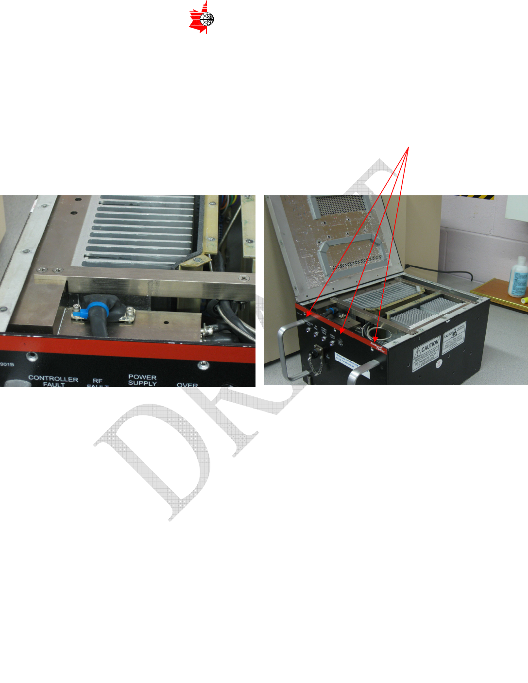
Four front−panel LED indicators are identified as follows:
• OVER TEMP: Illuminated when an overtemperature condition exists
(thermal limiting)
• POWER SUPPLY FAULT: Illuminated when an internal power supply
fault is detected
• RF FAULT: Illuminated when an internal RF fault is detected
• CONTROLLER FAULT: Illuminated when an internal control function
fault is detected.
The HPA has two external electrical connectors:
• Front Panel Connector
• Rear Panel Connector
The Front Panel Connector is MS3102 type circular connector. It is not wired or
used on the aircraft. This connector is for the HPA testing at the manufacturer
or another shop facility. This connector pin-out is indicated as in Figure 2.4.
The Rear Panel Connector is of the “low insertion force, shell size 2” type, as
defined in ARINC Specification 600. This connector is wired on the aircraft. It
provides main interface with ARINC 429 buses, discrete Mute control and SDI.
This connector pin-out is indicated as in Figure 2.5.
Page 8 of 42
ITS ELECTRONICS INC.
MICROWAVE COMPONENTS AND SUBSYSTEMS
The information contained herein is proprietary to ITS Electronics Inc. and is to be used by the recipient for the sole purpose for which it has been supplied.
It shall not be disclosed, in whole or in part to any other party without the prior written permission of ITS Electronics Inc.
Figure 2.1 HPA Architecture and Internal Layout
Page 9 of 42
ITS ELECTRONICS INC.
MICROWAVE COMPONENTS AND SUBSYSTEMS
The information contained herein is proprietary to ITS Electronics Inc. and is to be used by the recipient for the sole purpose for which it has been supplied.
It shall not be disclosed, in whole or in part to any other party without the prior written permission of ITS Electronics Inc.
Figure 2.2 HPA Front View
Figure 2.3 HPA Rear View
Page 10 of 42
ITS ELECTRONICS INC.
MICROWAVE COMPONENTS AND SUBSYSTEMS
The information contained herein is proprietary to ITS Electronics Inc. and is to be used by the recipient for the sole purpose for which it has been supplied.
It shall not be disclosed, in whole or in part to any other party without the prior written permission of ITS Electronics Inc.
Pin
Function Internal
Connection
A RS-232
Transmit To Controller
B RS-232 Receive
To Controller
C RS-232 Ground
To Controller
Figure 2.4 HPA Front Panel and Test Connector Details
Pin Function Internal
Connection
TP1A
ARINC 429
Input A To Controller
TP1B
ARINC 429
Input B To Controller
TP1C
ARINC 429
Output A To Controller
TP1D
ARINC 429
Output B To Controller
TP3A
HPA Mute
Top/Port A To Controller
TP3B
HPA Mute
Top/Port B To Controller
TP3C
HPA Mute
Starboard A To Controller
TP3D
HPA Mute
Starboard B To Controller
TP5A
SDI #1 To Controller
TP5B
SDI #2 To Controller
TP5D
SDI Common To Controller
TPC1
RF Input To RF Module
MPC1
RF Output To RF Module
BP1 115 VAC Input
(Hot) To Power
Supply
BP7 115 VAC Input
(Cold) To Power
Supply
BP8 Chassis Ground To Power
Supply
Figure 2.5 HPA Rear Connector Details
Top Plug
Bottom Plug
Page 11 of 42
ITS ELECTRONICS INC.
MICROWAVE COMPONENTS AND SUBSYSTEMS
The information contained herein is proprietary to ITS Electronics Inc. and is to be used by the recipient for the sole purpose for which it has been supplied.
It shall not be disclosed, in whole or in part to any other party without the prior written permission of ITS Electronics Inc.
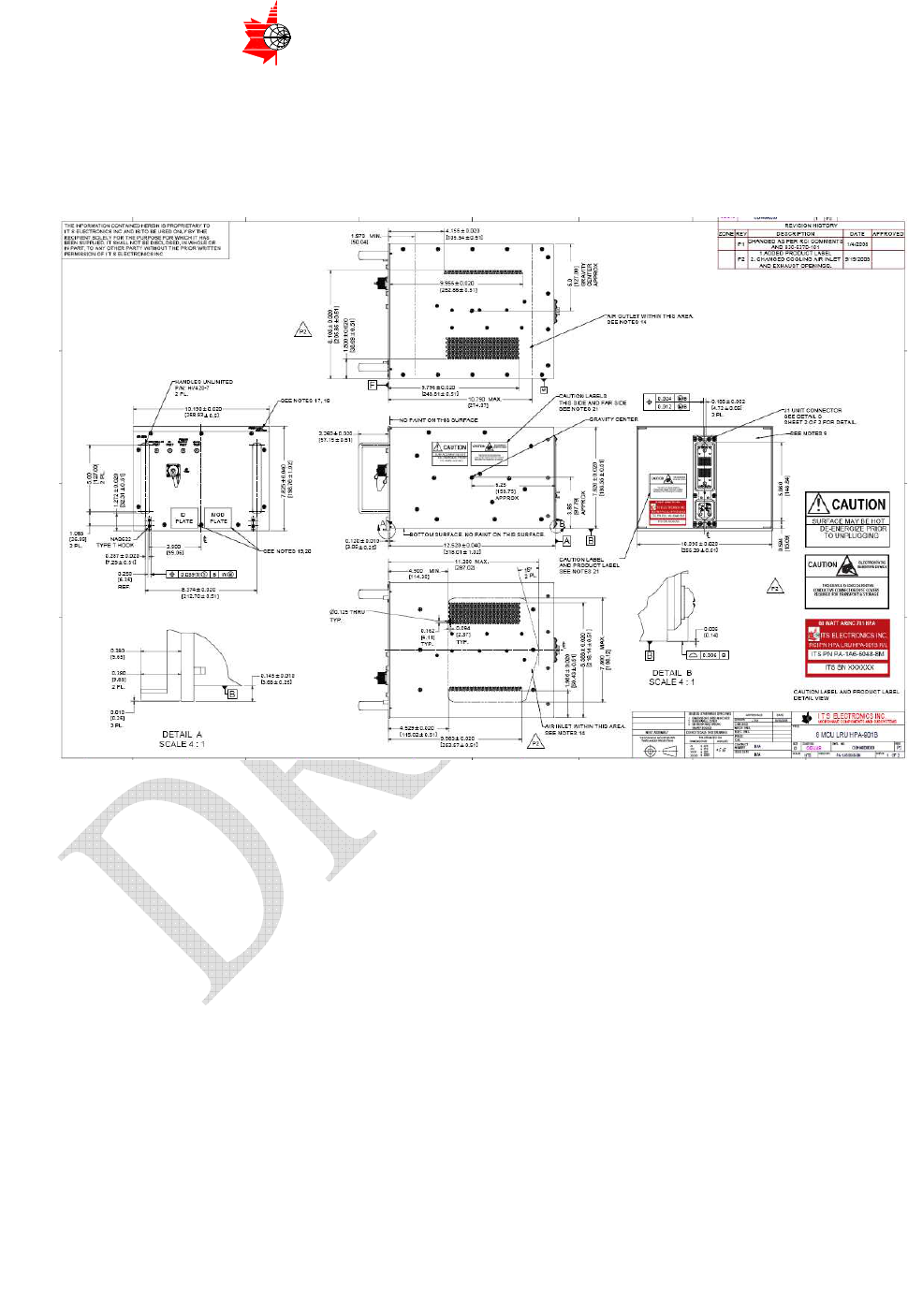
2.3 Mechanical Description
The HPA mechanical outline details are described in Figure 2.6 (Drawing
Number is ODH4800000
)
.
Figure 2.6 HPA Mechanical Outline
The HPA mechanical construction is illustrated in Figure 2.1.
The HPA is intended for installations on the aircraft in the Equipment Racks
that are compliant to the requirements of ARINC Specification 600. Therefore,
the HPA Enclosure is designed to conform to the ARINC Specification 600. The
Enclosure size is 8 Modular Concept Units (8-MCU).
The Enclosure assembly is comprised of:
• bottom, left and right side panel/chassis
• front panel
• rear panel
• top panel
• two handles
• two hold-down hooks
• associated hardware

Page 12 of 42
ITS ELECTRONICS INC.
MICROWAVE COMPONENTS AND SUBSYSTEMS
The information contained herein is proprietary to ITS Electronics Inc. and is to be used by the recipient for the sole purpose for which it has been supplied.
It shall not be disclosed, in whole or in part to any other party without the prior written permission of ITS Electronics Inc.
All Enclosure parts are metallic. The panels’ material is aluminum alloy. Interior
and bottom surface finish is chemical conversion coating. Exterior (except
bottom) surface finish is paint.
The HPA cooling medium is forced air moving through the HPA in the upward
or downward direction. To provide the interface between the HPA and the
aircraft cooling system, the Enclosure top and bottom panels have air
inlet/outlet apertures (sets of multiple individual openings).
The two Shop Replaceable Units are mounted to the sides of the Enclosure.
A low insertion force, shell size 2 Connector, as defined in ARINC Specification
600, is mounted to the rear panel.
An MS3201 type Connector is mounted to the front panel.
The four LEDs are mounted to the front panel.
The two handles and two hold-down hooks are mounted to the front panel.
The forced air enters either from the inlet of the top lid or from the bottom lid
and goes through the heat sinks of the two SRUs to cool the internal
components. The hot air exits from the outlet of the opposite lid.
2.4 The HPA Family Tree and Block Diagram
The HPA consists of the following SRUs:
• Power Supply, Monitoring, Control and Pilot Tone (PSMCPT) Module
(Part No. H4800200)
• RF Module (Part No. H4800900)
3 LRU on-line Fault Diagnosis
HPA has BIT to provide seven-byte information for fault diagnosis purpose. The
details of the BIT information are in Table 3.1. Each state has its own hex-value
“mask” when turned on. The masks of the turned on states aggregate to the hex
value of a byte. For example, if “Low Input Power” (mask “02”) and “Input Power
Overdrive” (mask “04”) are turned on, the hex value of the first byte will be “06” (i.e.
“02”+”04”).
In Table 3.1, only the states marked in the “Fault” column turned on will represent
LRU failure.

Page 13 of 42
ITS ELECTRONICS INC.
MICROWAVE COMPONENTS AND SUBSYSTEMS
The information contained herein is proprietary to ITS Electronics Inc. and is to be used by the recipient for the sole purpose for which it has been supplied.
It shall not be disclosed, in whole or in part to any other party without the prior written permission of ITS Electronics Inc.
Effect
Flag Byte
No. Mask
Description Mute +32V Shutdown Fault
01 Return Loss
02 Low Input Power
04 Input Power Overdrive
08 Output Power Too High X
10 N/A
20 N/A
40 N/A
Pwr 1
80 N/A
01 HPA 1 Over-Temp Warning
02 HPA 1 Over-Temp Mute X
04 HPA 1 Over-Temp
Shutdown X X
08 HPA 1 Under-Temp
10 HPA 2 Over-Temp Warning
20 HPA 2 Over-Temp Mute X
40 HPA 2 Over-Temp
Shutdown X X
t1 2
80 HPA 2 Under-Temp
01 MCU Over-Temp Warning
02 MCU Over-Temp Mute X
04 MCU Over-Temp
Shutdown X X
08 MCU Under-Temp
10 N/A
20 N/A
40 N/A
t2 3
80 N/A
01 9V Over-Voltage x
02 32V Over-Voltage x
04 Spare Over-Voltage
08 N/A
10 32V Over-Current
Measured X X x
20 32V Over-Current Low
Cutoff X x
40 32V Over-Current High
Cutoff X X x
Ov 4
80 N/A
01 9V Under-Voltage x
02 32V Under-Voltage x
04 Spare Under-Voltage
08 N/A
10 32V Under-Current
Measured x
Uv 5
20 N/A
Page 14 of 42
ITS ELECTRONICS INC.
MICROWAVE COMPONENTS AND SUBSYSTEMS
The information contained herein is proprietary to ITS Electronics Inc. and is to be used by the recipient for the sole purpose for which it has been supplied.
It shall not be disclosed, in whole or in part to any other party without the prior written permission of ITS Electronics Inc.
40 N/A
80 N/A
01 Application ROM CRC X x
02 EEPROM CRC X x
04 RAM Array Fault X x
08 RAM Data Line Fault X x
10 RAM Addr Line Fault X x
20 N/A
40 N/A
Mem 6
80 N/A
01 Pilot Tone Tx Lock X x
02 Pilot Tone Rx Lock X x
04 ARINC Rx Timeout
08 ARINC HW Failure x
10 N/A
20 N/A
40 N/A
Msc 7
80 N/A
Table 3.1 Seven-byte BIT information matrix

Page 15 of 42
ITS ELECTRONICS INC.
MICROWAVE COMPONENTS AND SUBSYSTEMS
The information contained herein is proprietary to ITS Electronics Inc. and is to be used by the recipient for the sole purpose for which it has been supplied.
It shall not be disclosed, in whole or in part to any other party without the prior written permission of ITS Electronics Inc.
3.1 LRU Remove/Replace/Back-to-Normal-Status Verification Procedures
Once the LRU BIT test shows “FAULT” state, follow the below described procedures
to remove the faulty LRU from the aircraft and install a replacement LRU.
Send the faulty LRU back to the original manufacturer for repair.
3.2 Tool list
No tools are needed.
3.3 LRU Removal Procedures
WARNING:
THE HPA LRU WEIGHS 30 LBS
REMOVE IT WITH CARE TO PREVENT PERSONAL INJURY
Step 1: Release the two hold-down hooks and pull out the LRU from the rack
3.4 LRU Installation Procedures
WARNING:
THE HPA LRU WEIGHS 30 LBS
INSTALL IT WITH CARE TO PREVENT PERSONAL INJURY
Step 1: Push the LRU into the rack and fix the two hold-down hooks
3.5 LRU Repair Verification Procedures
After installing the LRU properly by the above procedures, check if the BIT
result shows no error.

Page 16 of 42
ITS ELECTRONICS INC.
MICROWAVE COMPONENTS AND SUBSYSTEMS
The information contained herein is proprietary to ITS Electronics Inc. and is to be used by the recipient for the sole purpose for which it has been supplied.
It shall not be disclosed, in whole or in part to any other party without the prior written permission of ITS Electronics Inc.
4 LRU Shop Testing, Fault Isolation and Procedures
4.1 LRU Test Environment Setup Procedures
Test Conditions
Unless specified otherwise, the tests shall be performed at the following
conditions:
Ambient Temperature: +25°C ±5°C
Altitude: 0 to 6,000 feet mean sea level
Vibration and Shock: None
Relative Humidity: 20% to 85%, non-condensing
Power Source: 115.0 ±2.3 VAC at 400 ±8 Hertz
Forced Air Cooling (minimum air flow rate): 34 Kg/hr
Suggested Test Equipment
Arbitrary Waveform Generator - Agilent PSG-D Series E8267C
ARINC Bus Box - Ballard Model BB1020
Signal Generators 1 and 2 - Hewlett-Packard 8648C
Splitter - Mini-Circuits ZFSC-2-2500
Power Meter - Hewlett-Packard E4419B
Power Sensors - Hewlett-Packard 9300A
Spectrum Analyzer - Hewlett-Packard E4407B
High Power RF Cable - 500 W, N-male to N-male
Directional Coupler - 10 dB, A.M.Electronics SMC4030-10
40 dB Attenuator - 100 W, Weinschel 48-40-XX
10 dB Attenuator - Mini-Circuits BW-S10W2
Personal Computer - with standard serial port and USB port
Power Supply - Hewlett-Packard 6813A
Note
The test equipment models listed here are for reference only. Available
equivalents may be used.
Note
The Arbitrary Waveform Generator may be substituted with the Signal
Generator 1 for single-tone measurements, and with the Signal Generators
1 and 2 and the Splitter for two-tone measurements.
Page 17 of 42
ITS ELECTRONICS INC.
MICROWAVE COMPONENTS AND SUBSYSTEMS
The information contained herein is proprietary to ITS Electronics Inc. and is to be used by the recipient for the sole purpose for which it has been supplied.
It shall not be disclosed, in whole or in part to any other party without the prior written permission of ITS Electronics Inc.
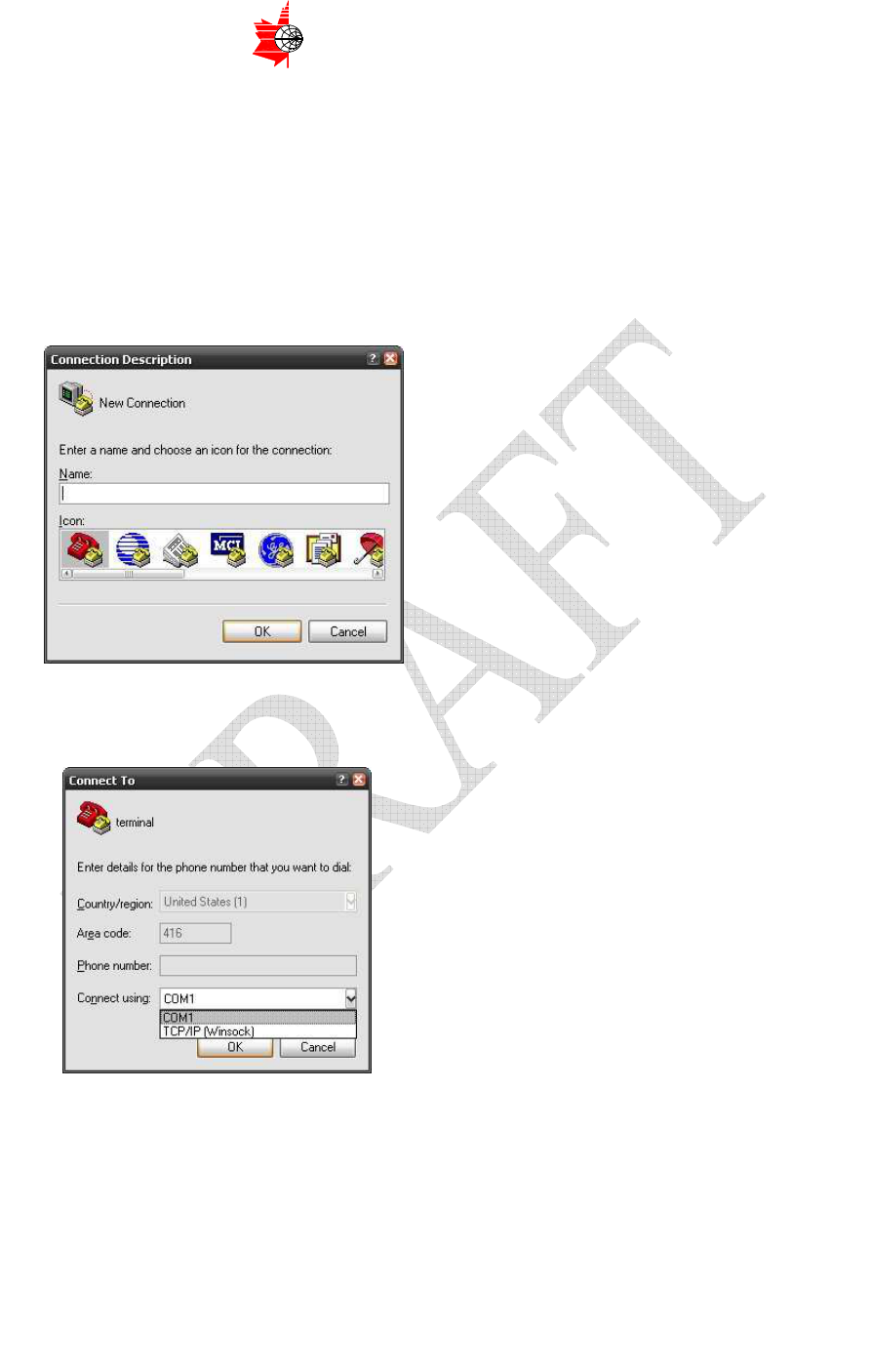
4.2 PC Test Environment Setup Procedures
1. Use mouse to click “Start”, then choose “Programs”, then click
“Accessories”, then “Communications” and then choose
“Hyperterminal”
2. A setup window, as in Figure 4.1, will show up. Enter a name that you
want to give to the connection, choose an icon for the connection and
click “OK”
Figure 4.1 Hyperterminal setup (1)
3. A connection setup window, as in Figure 4.2, will show up. Choose the
appropriate connection port and click “OK”
Figure 4.2 Hyperterminal setup (2)
4. A port property setup window, as in Figure 4.3, will show up. Choose
the values as shown in Figure 4.3 and click “OK”
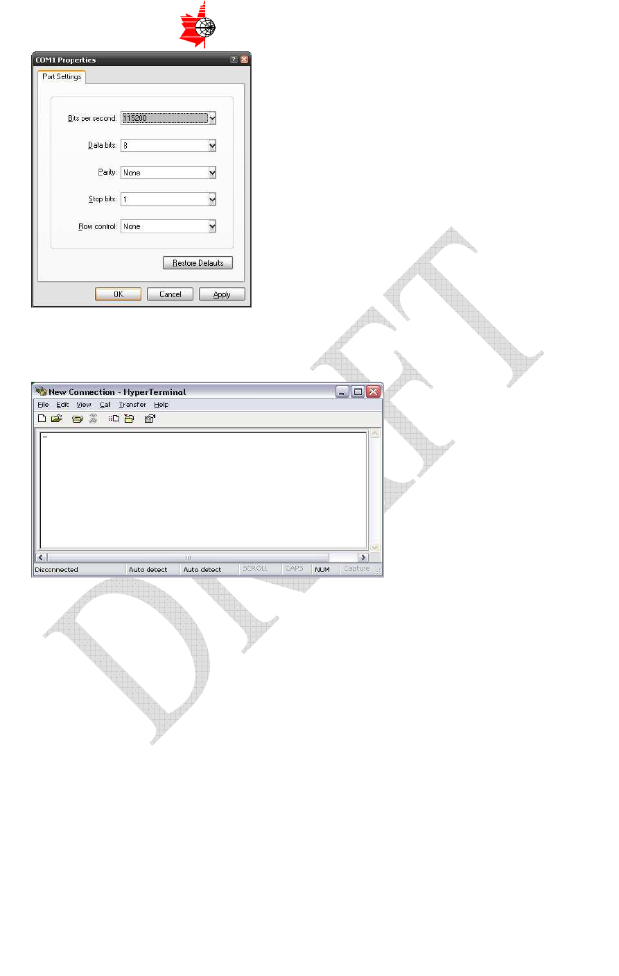
Page 18 of 42
ITS ELECTRONICS INC.
MICROWAVE COMPONENTS AND SUBSYSTEMS
The information contained herein is proprietary to ITS Electronics Inc. and is to be used by the recipient for the sole purpose for which it has been supplied.
It shall not be disclosed, in whole or in part to any other party without the prior written permission of ITS Electronics Inc.
Figure 4.3 Hyperterminal setup (3)
5. A text-based Hyperterminal window will show up as in Figure 4.4.
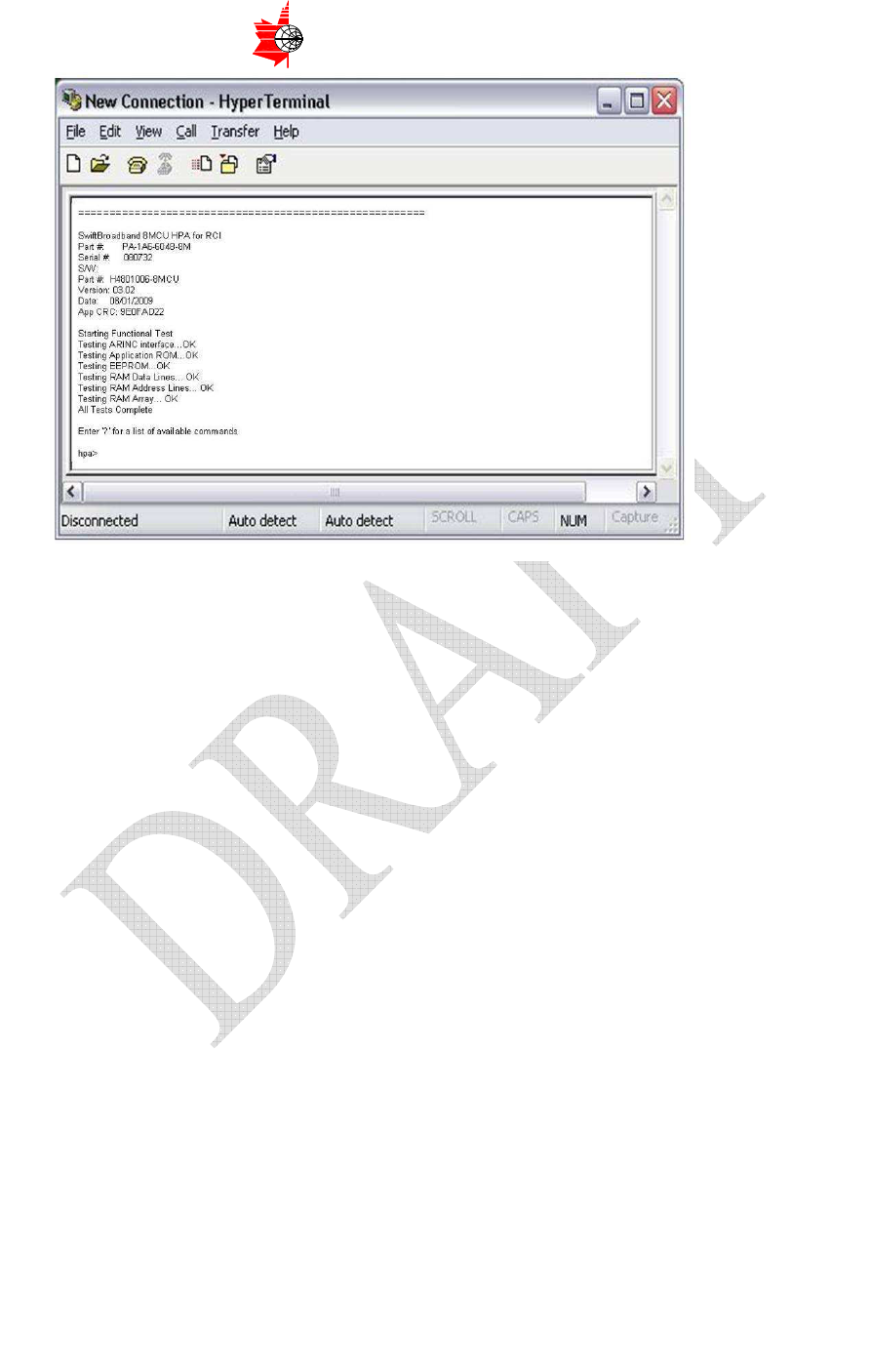
Figure 4.4 Hyperterminal setup (4)
6. After few seconds, a welcome message and command prompt will
show up as in Figure 4.5. If nothing shows up, check the connection
cable and setup. If connection is correct, then it means the LRU has
failed.
Page 19 of 42
ITS ELECTRONICS INC.
MICROWAVE COMPONENTS AND SUBSYSTEMS
The information contained herein is proprietary to ITS Electronics Inc. and is to be used by the recipient for the sole purpose for which it has been supplied.
It shall not be disclosed, in whole or in part to any other party without the prior written permission of ITS Electronics Inc.
Figure 4.5 Hyperterminal setup (5)
4.3 LRU Hardware Fault Verification Procedures
Fault Verification by BIT
Step 1: After connecting the LRU to PC and test equipments and setting
up the Hyperterminal in PC properly, if nothing shows up, then it
means the LRU failed.
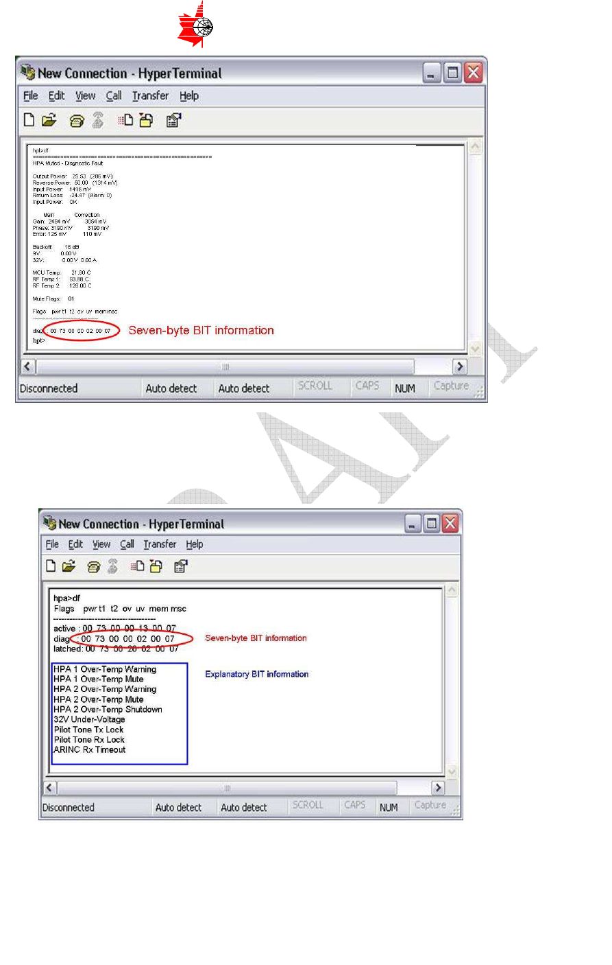
Step 2: Type the command “d1” (note: it is the numerical digit “one”, not the
alphabet “l”) and press “enter”. The diagnostic information will be
shown in Figure 4.6 as an example.
The seven hex-value numbers, titled as “diag”, in Figure 4.6
represent the seven bytes of BIT results.
Page 20 of 42
ITS ELECTRONICS INC.
MICROWAVE COMPONENTS AND SUBSYSTEMS
The information contained herein is proprietary to ITS Electronics Inc. and is to be used by the recipient for the sole purpose for which it has been supplied.
It shall not be disclosed, in whole or in part to any other party without the prior written permission of ITS Electronics Inc.
Figure 4.6 BIT diagnostic information
Step 3: Type the command “df” and press “enter”, the explanatory BIT
diagnostic information will be displayed as in Figure 4.7.
Figure 4.7 Explanatory BIT diagnostic information
For example, in Figure 4.6 and Figure 4.7, the second BIT byte is “73” in hex
value. By Table 3.1, this is equivalent to “01”+“02”+”10”+”20”+”40”, which
Page 21 of 42
ITS ELECTRONICS INC.
MICROWAVE COMPONENTS AND SUBSYSTEMS
The information contained herein is proprietary to ITS Electronics Inc. and is to be used by the recipient for the sole purpose for which it has been supplied.
It shall not be disclosed, in whole or in part to any other party without the prior written permission of ITS Electronics Inc.
means “HPA 1 Over-Temp Warning”, “HPA 1 Over-Temp Mute”, “HPA 2
Over-Temp Warning”, “HPA 2 Over-Temp Mute” and “HPA 2 Over-Temp
Shutdown” as in the first five lines of the explanatory message in Figure 4.7.
The fifth BIT byte is “02”, which means “32V Under-Voltage” as in the sixth
line of the explanatory message in Figure 4.7. The seventh BIT byte is “07”
(ie. “01”+”02”+”04”), which means “Pilot Tone Tx Lock”, “Pilot Tone Rx Lock”
and “ARINC Rx Timeout” according to Table 3.1, as in the last three lines of
the explanatory message in Figure 4.7.
Since “32V Under-Voltage”
is turned on here and marked as a “FAULT State”
in Table 3.1, we can conclude that the LRU is faulty.
Fault Verification by Acceptance Test Procedures (ATP)
If BIT test shows no fault, test the “Intermodulation, Power Dissipation” per
ATP by the following procedures.
Run the ARINC 429 user interface software (filename “RCI HPA-901B
ARINC429 M&C.exe”) on the PC.
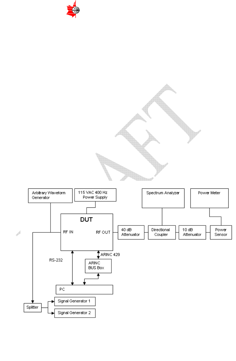
Step 1: Connect the Arbitrary Waveform Generator to the RF IN of the DUT as
shown in Figure 4.8.
Figure 4.8 ATP setup

Page 22 of 42
ITS ELECTRONICS INC.
MICROWAVE COMPONENTS AND SUBSYSTEMS
The information contained herein is proprietary to ITS Electronics Inc. and is to be used by the recipient for the sole purpose for which it has been supplied.
It shall not be disclosed, in whole or in part to any other party without the prior written permission of ITS Electronics Inc.
Step 2: Set the output power of the Arbitrary Waveform Generator to two tone
mode, –14 dBm total power. Or, if using two separate signal generators, set the
output power of each tone to -17 dBm.
Step 3: Set the tone frequencies to 1626.5 and 1660.5 MHz (band middle, 34 MHz
spacing).
Step 4: Apply power to the DUT as required.
Step 5: Set the DUT gain to the 0 dB back-off.
Step 6: Adjust output power of the Arbitrary Waveform Generator so that the
output of the DUT is 47.8 dBm (60W).
Step 7: Measure the intermodulation product level and AC power consumption.
Step 8: Calculate power dissipation by subtracting 60 Watt from the measured AC
power consumption.
Step 9: Reduce the output power of the DUT to 47 dBm (50W).
Step 10: Measure the intermodulation product level.
Step 11: If the results are beyond the threshold limits as stated in Table 4.1, the
LRU has failed the test.

Page 23 of 42
ITS ELECTRONICS INC.
MICROWAVE COMPONENTS AND SUBSYSTEMS
The information contained herein is proprietary to ITS Electronics Inc. and is to be used by the recipient for the sole purpose for which it has been supplied.
It shall not be disclosed, in whole or in part to any other party without the prior written permission of ITS Electronics Inc.
4.4 SRU Hardware Fault Isolation Procedures
From the results of the test procedures described above, the faulty SRU can be
isolated according to Table 4.1.
Shop Diagnostic Results
Test Threshold limits beyond which
represent LRU failure status
Most
likely
faulty
SRU
2nd most
likely faulty
SRU
BIT 9V Over Voltage
PSCPT -
BIT 32V Over Voltage
PSCPT -
BIT 32V Over-Current Measured
RF Module PSMCPT Module
BIT 32V Over-Current Low Cutoff
RF Module PSMCPT Module
BIT 32V Over-Current High Cutoff
RF Module PSMCPT Module
BIT 9V Under-Voltage
PSMCPT
Module -
BIT 32V Under-Voltage
PSMCPT
Module -
BIT 32V Under-Current Measured
RF Module PSMCPT Module
BIT Application ROM CRC
PSMCPT
Module -
BIT EEPROM CRC
PSMCPT
Module -
BIT RAM Array Fault
PSMCPT
Module -
BIT RAM Data Line Fault
PSMCPT
Module -
BIT RAM Addr Line Fault
PSMCPT
Module -
BIT Pilot Tone Tx Lock
PSMCPT
Module -
BIT Pilot Tone Rx Lock
PSMCPT
Module -
BIT ARINC HW Failure
PSMCPT
Module -
Intermodulation product level at 60W
should be −31.5 dBc or lower
RF Module PSMCPT Module
Intermodulation product level at 50W
should be −42.5 dBc or lower
RF Module PSMCPT Module
ATP
Paragraph
7.1.5 The power consumption shall not exceed
300 W
RF Module PSMCPT Module
Table 4.1 SRU Fault Isolation Criteria
Page 24 of 42
ITS ELECTRONICS INC.
MICROWAVE COMPONENTS AND SUBSYSTEMS
The information contained herein is proprietary to ITS Electronics Inc. and is to be used by the recipient for the sole purpose for which it has been supplied.
It shall not be disclosed, in whole or in part to any other party without the prior written permission of ITS Electronics Inc.
5 Disassembly Instruction of the HPA−901B
5.1 General: this section describes how to disassemble the High Power
Amplifier HPA-901B
5.2 Materials: Refer to Table A1 in Appendix A for the parts necessary to
assemble the unit
5.3 Disassembly Procedure
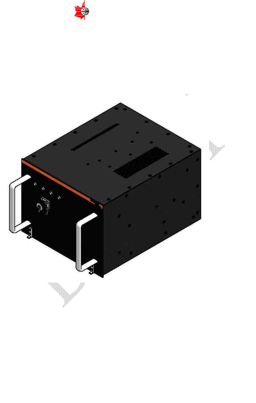
Figure 5.1 Fully Assembled HPA−901B
Page 25 of 42
ITS ELECTRONICS INC.
MICROWAVE COMPONENTS AND SUBSYSTEMS
The information contained herein is proprietary to ITS Electronics Inc. and is to be used by the recipient for the sole purpose for which it has been supplied.
It shall not be disclosed, in whole or in part to any other party without the prior written permission of ITS Electronics Inc.
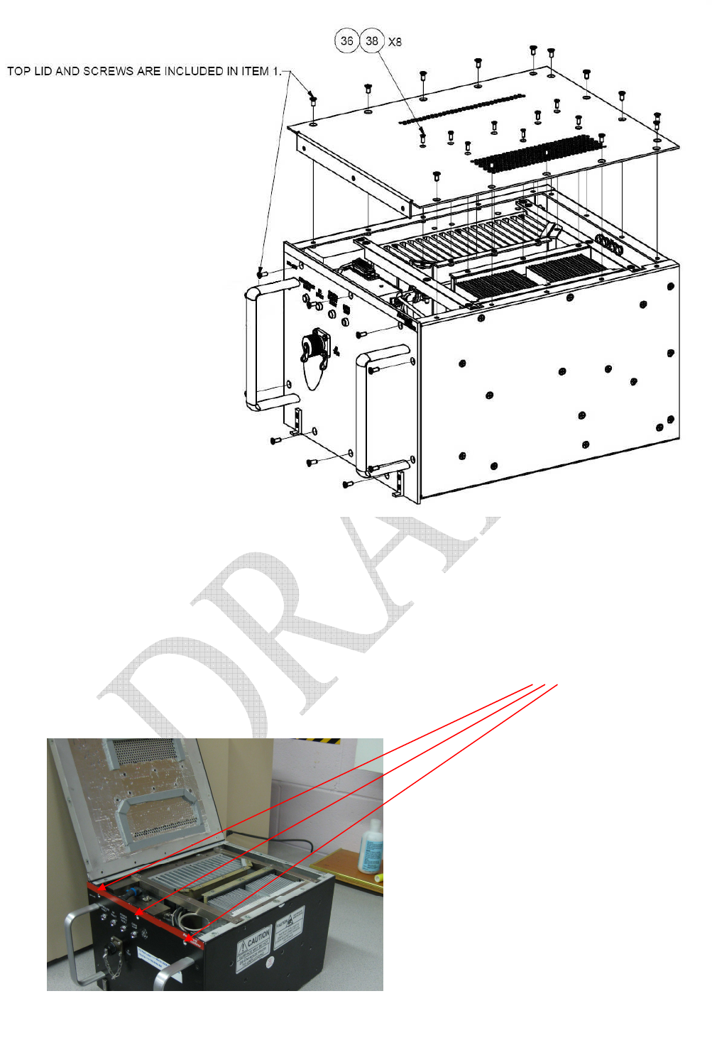
5.4 Top Lid and Front Panel Disassembly
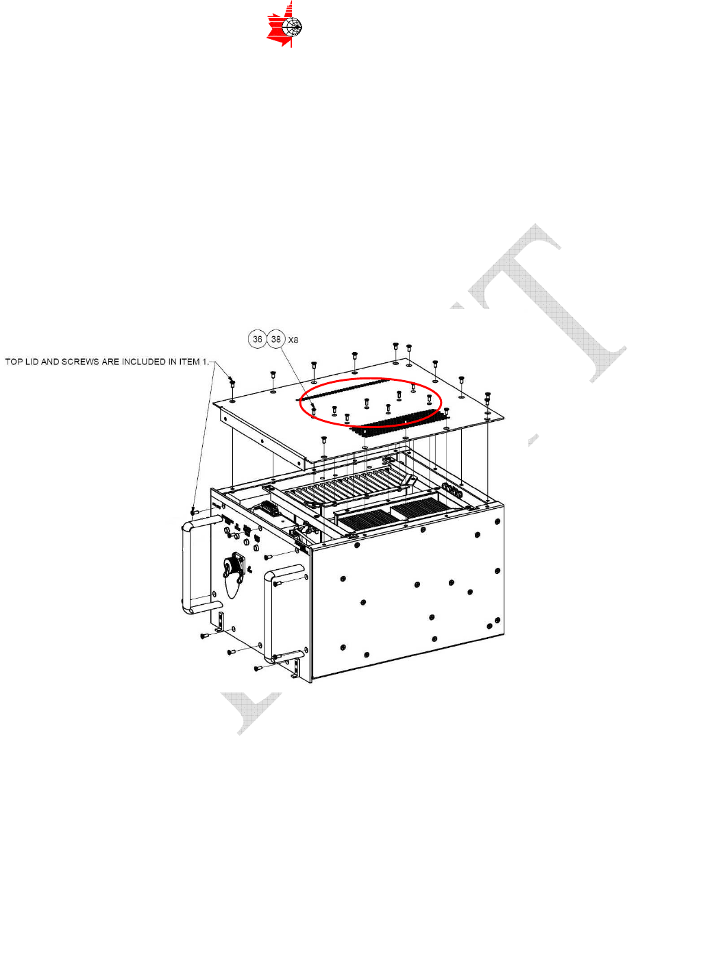
− Remove eight #4-40 x 5/16" Flat Head Philips Screws (38) that secure the HPA
Lid Assembly to the Housing (Figure 5.1).
− Remove the rest of the Flat Head Philips Screws from the top lid. All screws have
been assembled with Loctite locking compound, so higher initial torque force
must be applied to unlock the screws
− Remove top three screws from the front panel as shown on the Figure 5.2.
− Remove Top Panel
Figure 5.2 HPA with Removed Lid
Figure 5.1
Page 26 of 42
ITS ELECTRONICS INC.
MICROWAVE COMPONENTS AND SUBSYSTEMS
The information contained herein is proprietary to ITS Electronics Inc. and is to be used by the recipient for the sole purpose for which it has been supplied.
It shall not be disclosed, in whole or in part to any other party without the prior written permission of ITS Electronics Inc.
5.5 Front Panel Disassembly
− Remove two #4x40 3/8” Screws to uninstall D-Sub Connector (2) from the
housing (see Figure 5.3)
− Remove the rest of the screws from the front panel
− Remove front panel
Figure 5.3
Page 27 of 42
ITS ELECTRONICS INC.
MICROWAVE COMPONENTS AND SUBSYSTEMS
The information contained herein is proprietary to ITS Electronics Inc. and is to be used by the recipient for the sole purpose for which it has been supplied.
It shall not be disclosed, in whole or in part to any other party without the prior written permission of ITS Electronics Inc.
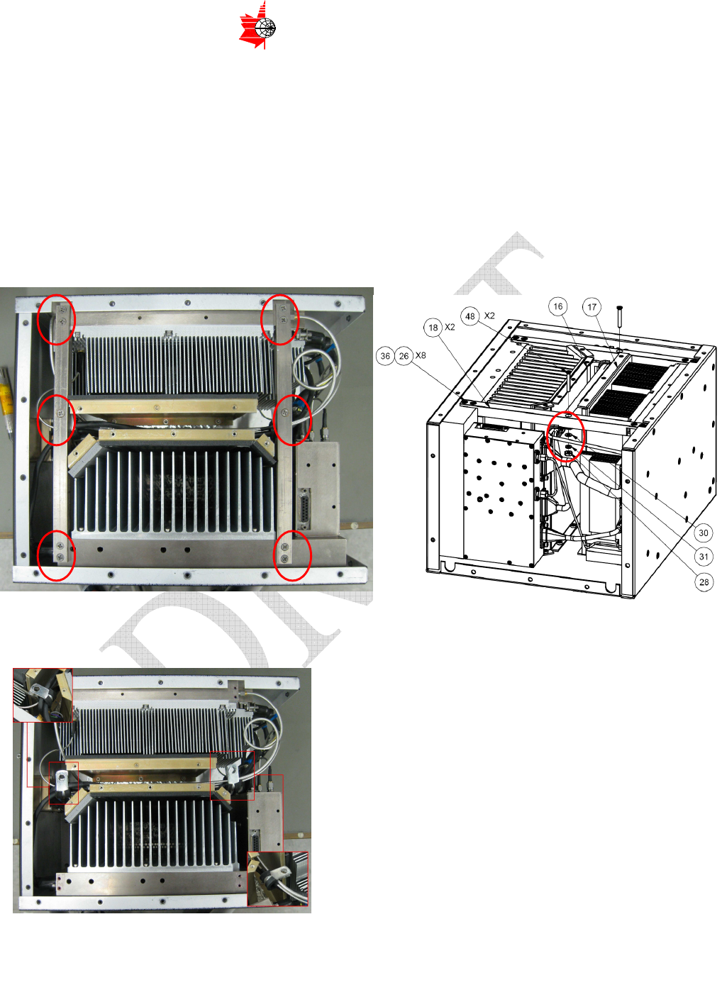
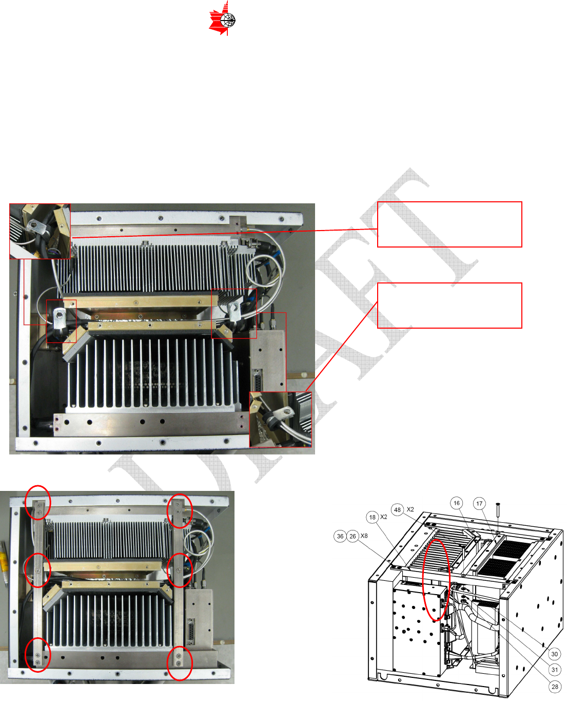
5.6 Top Bracket Removal
− Remove #4-40 x 5/16" Flat Head Philips Screws (36) holding two top brackets
(18).
− Remove two middle screws item (48) securing two steel plated clamps item
(47). Please note – middle screws have hardware on the back side of the
bracket. See Figure 5.3 a) and b) below
− Remove the clamps item (47) holding cables and harnesses together. See
Figure 5.5
a) Figure 5.4 b)
Figure 5.5 Top view after brackets removed
Page 28 of 42
ITS ELECTRONICS INC.
MICROWAVE COMPONENTS AND SUBSYSTEMS
The information contained herein is proprietary to ITS Electronics Inc. and is to be used by the recipient for the sole purpose for which it has been supplied.
It shall not be disclosed, in whole or in part to any other party without the prior written permission of ITS Electronics Inc.
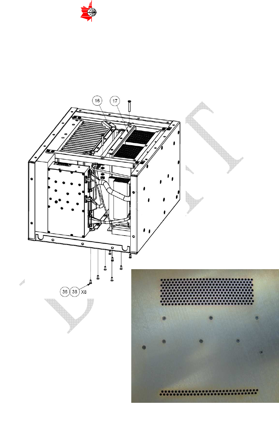
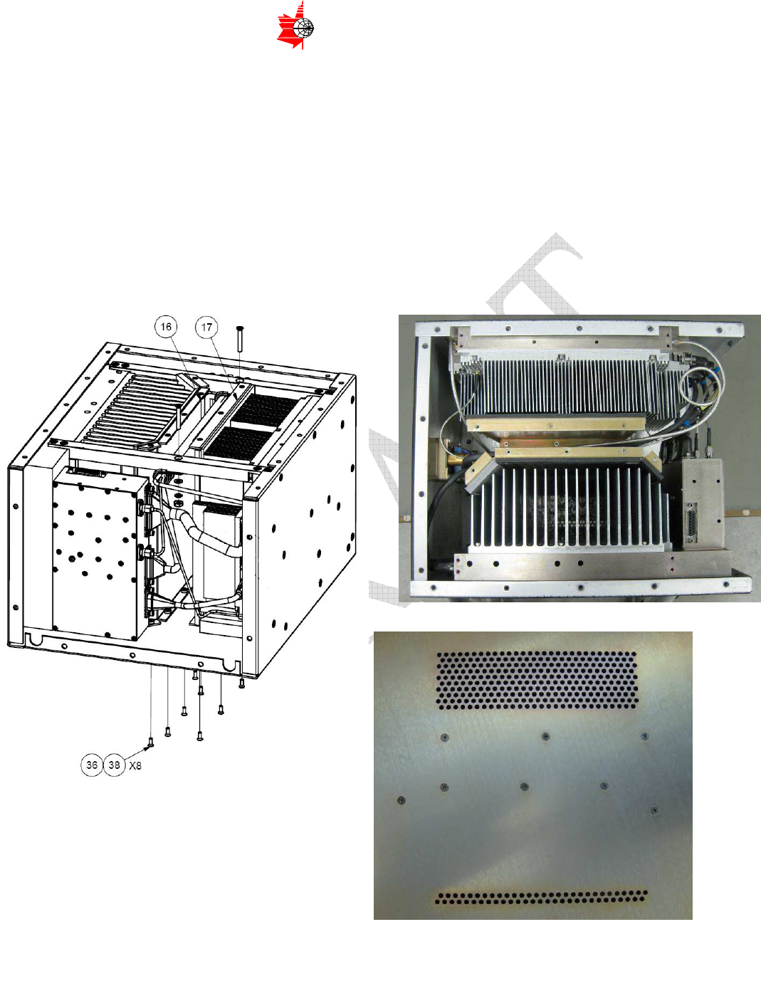
5.7 RF and DC Heat-sink Gasket Cover Assemblies Removal
− Remove 8 screws item (38) located on the bottom cover Figure 5.6 a) and b)
in order to uninstall RF and DC Heat-sink Gasket Cover Assemblies items
(16) and (17). Please note, all the screws are locked with Loctite 290
compound, so higher initial torque force must be applied
a)
Figure 5.6 b)
Page 29 of 42
ITS ELECTRONICS INC.
MICROWAVE COMPONENTS AND SUBSYSTEMS
The information contained herein is proprietary to ITS Electronics Inc. and is to be used by the recipient for the sole purpose for which it has been supplied.
It shall not be disclosed, in whole or in part to any other party without the prior written permission of ITS Electronics Inc.
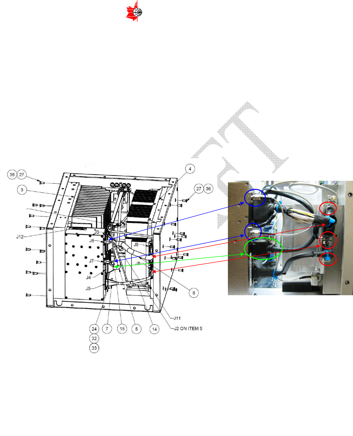
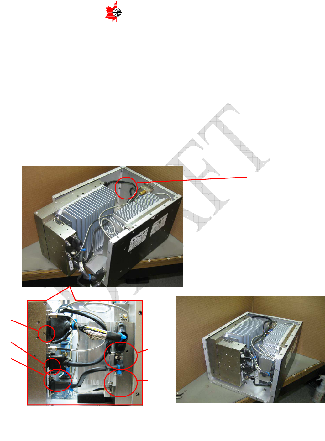
5.8 Power Supply Removal
− Remove four screws from J8 and J9 of RF module as shown on the picture
Figure 5.7 a) and b) (shown with red arrows) then disconnect Pilot Tone
Cables 1 and 2. items (14) and (15)
− Disconnect J6 and J7 Semi-rigid cable connectors of the Power Supply
Module (shown with blue arrows)
− Remove screws item (27) from the left side cover of the drawing Figure 5.7 to
uninstall Power Supply sub-assembly
− In order to remove Power Supply assembly first shift it for approximately 3’’ to
gain the access to the rest of the cables and then remove two connectors (J4
and J15 shown on the drawings Figure 5.7 a) and b) and on Figure 5.8 a) and
b) with green color)
− Remove Power Supply from the housing
b)
a) Figure 5.7
Page 30 of 42
ITS ELECTRONICS INC.
MICROWAVE COMPONENTS AND SUBSYSTEMS
The information contained herein is proprietary to ITS Electronics Inc. and is to be used by the recipient for the sole purpose for which it has been supplied.
It shall not be disclosed, in whole or in part to any other party without the prior written permission of ITS Electronics Inc.
a) b)
Figure 5.8
Figure 5.9 Power Supply Assembly
Page 31 of 42
ITS ELECTRONICS INC.
MICROWAVE COMPONENTS AND SUBSYSTEMS
The information contained herein is proprietary to ITS Electronics Inc. and is to be used by the recipient for the sole purpose for which it has been supplied.
It shall not be disclosed, in whole or in part to any other party without the prior written permission of ITS Electronics Inc.
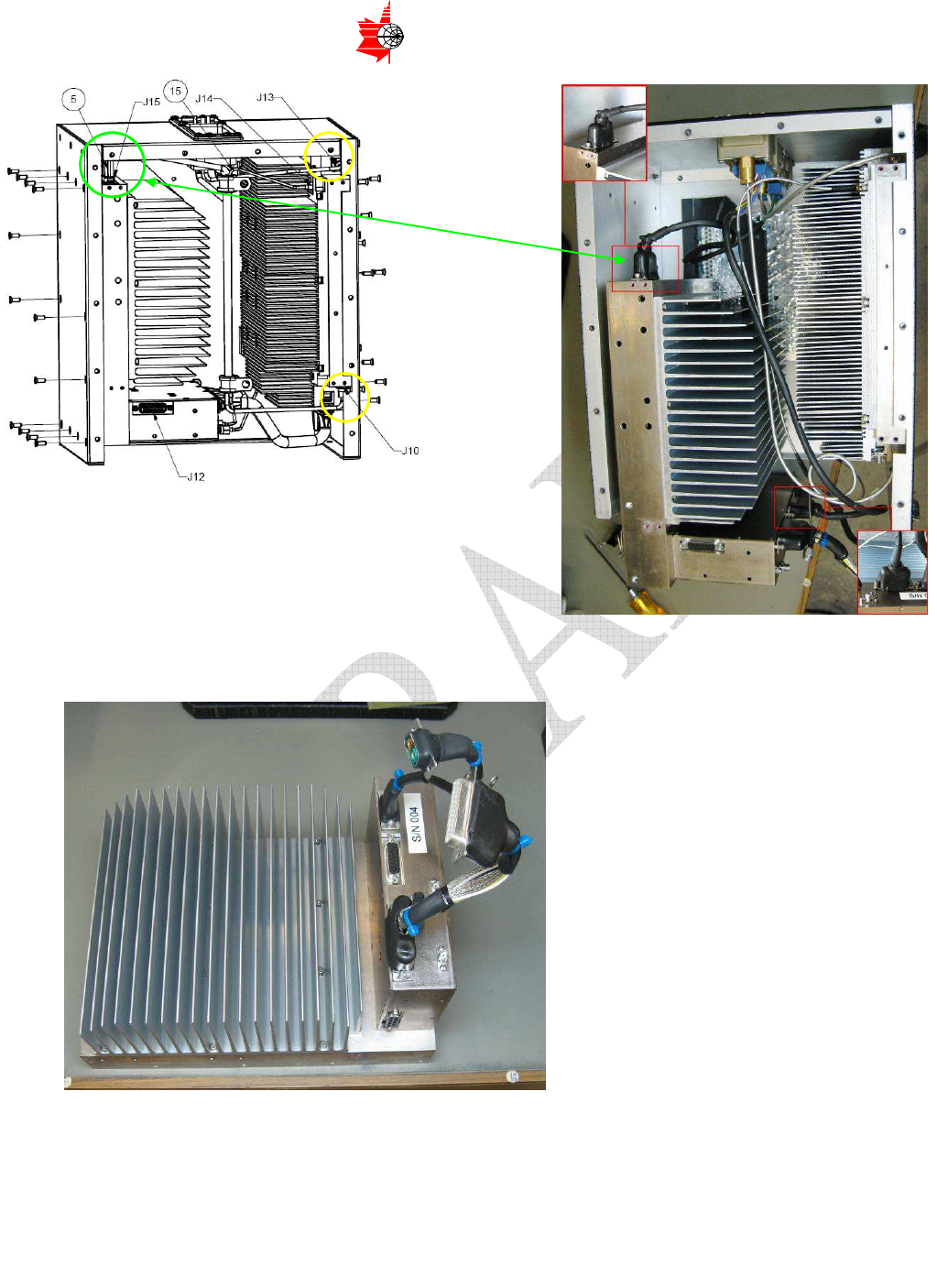
5.9 RF Module Removal:
− Remove all the screws item (27) holding RF Module from the right side on the
Figure 5.7 a). Please note all screws are locked with Loctite 290 compound,
so higher initial torque force must be applied
− Shift RF Module off the side panel for approx. 2" distance
− Disconnect two Semi-rigid Cables J10 and J13 at locations shown on Figure
5.8 a) with yellow circles and on the Figure 5.10 below
− Remove RF Module from the housing
Figure 5.10
Figure 5.11 RF Module Sub-assembly
J13 J10

Page 32 of 42
ITS ELECTRONICS INC.
MICROWAVE COMPONENTS AND SUBSYSTEMS
The information contained herein is proprietary to ITS Electronics Inc. and is to be used by the recipient for the sole purpose for which it has been supplied.
It shall not be disclosed, in whole or in part to any other party without the prior written permission of ITS Electronics Inc.
6 Cleaning
− No cleaning operation for HPA901B is required
7 Check
− Checking is limited to visual inspection of the following
• Ensure that the air channels are not obstructed.
• Ensure that all connectors are secure.
• Ensure that the HPA is mounted securely.
8 Repair
− Because of the complexity of the HPA901B, field servicing is not practical.
Should a fault be identified within a unit, the unit should be returned to the
factory, in its original packing material if possible, for repair or replacement.
− Refurbished replacement units will be functionally tested prior to being
shipped to the customer. Based on the type of fault, ITS Electronics Inc. will
determine the types of tests required to verify the integrity and serviceability
of the unit. These tests will be listed on the functional test sheet that
accompanies the unit.
Page 33 of 42
ITS ELECTRONICS INC.
MICROWAVE COMPONENTS AND SUBSYSTEMS
The information contained herein is proprietary to ITS Electronics Inc. and is to be used by the recipient for the sole purpose for which it has been supplied.
It shall not be disclosed, in whole or in part to any other party without the prior written permission of ITS Electronics Inc.
9 Assembly
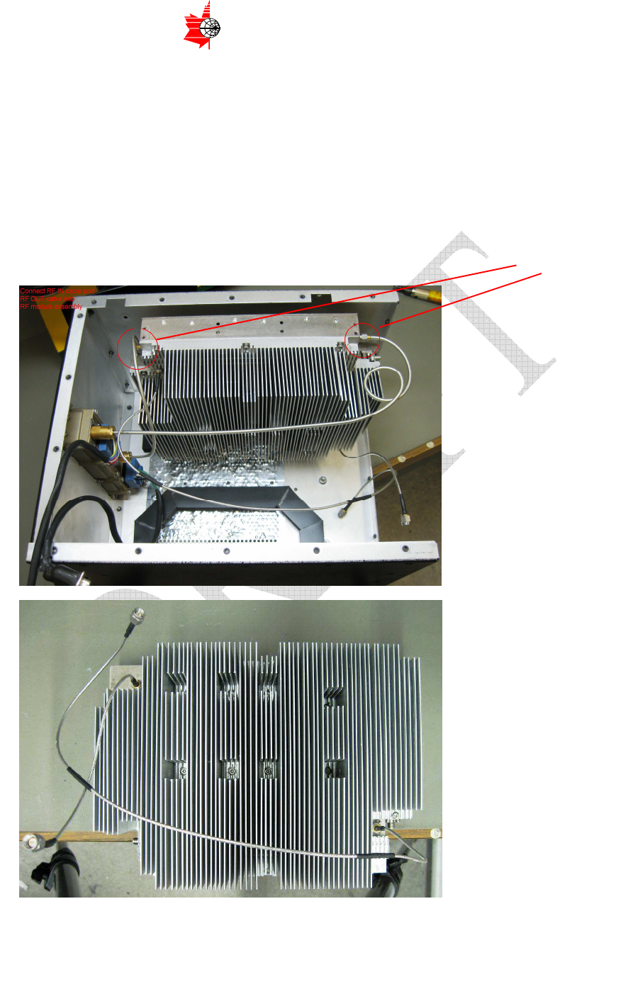
9.1 RF Module Installation
− Place RF Module into the housing Figure 8.1 a)
− Connect Semi-rigid Cables to J10 and J13 as shown on Figure 8.1 b)
− Install 13 screws item (27) securing RF module to the housing.
All screws must be assembled with Loctite 290 locking compound
a) Figure 8.1 b)
J13 J10
Page 34 of 42
ITS ELECTRONICS INC.
MICROWAVE COMPONENTS AND SUBSYSTEMS
The information contained herein is proprietary to ITS Electronics Inc. and is to be used by the recipient for the sole purpose for which it has been supplied.
It shall not be disclosed, in whole or in part to any other party without the prior written permission of ITS Electronics Inc.
9.2 Power Supply Installation
− Place Power Supply onto the housing away from the back cover to more
easily plug connectors and cables as shown on the Figure 8.2 a)
− Install two connectors J4 and J15 as shown on the drawings Figure 8.2 a)
and b)
− Install Pilot Tone Cables 1 and 2 item (14) and (15) – J6 and J7 of the Power
Supply Module and J8 and J9 of RF module as shown on the picture Figure
8.2 b)
− Align Power Supply Module mounting holes with side cover
− Install 12 screws item (27) as shown on the drawing Figure 5.7 to secure
Power Supply sub-assembly in place
All screws must be assembled with Loctite 290 locking compound
Figure 8.2
a)
c)
b) Installed RF and Power Supply
J4
J15
J6
J7
J8
J9
Page 35 of 42
ITS ELECTRONICS INC.
MICROWAVE COMPONENTS AND SUBSYSTEMS
The information contained herein is proprietary to ITS Electronics Inc. and is to be used by the recipient for the sole purpose for which it has been supplied.
It shall not be disclosed, in whole or in part to any other party without the prior written permission of ITS Electronics Inc.
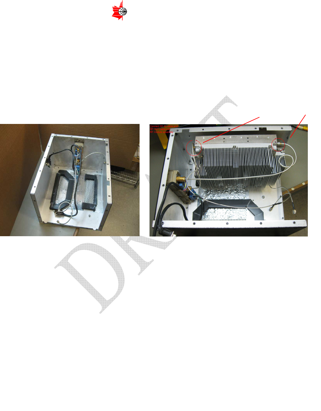
9.3 RF and DC Heat-sink Gasket Cover Assemblies Installation
− Place items(16) and (17) - RF and DC Heat-sink Gasket Cover Assemblies
into the housing as shown on the Figure 8.3 a) and b)
− Install 8 screws item (38) to the bottom cover Figure 8.3 a) and c) in order to
secure RF and DC Heat-sink Gasket Cover Assemblies.
All screws must be assembled with Loctite 290 locking compound
b)
a)
Figure 8.3 c)
Page 36 of 42
ITS ELECTRONICS INC.
MICROWAVE COMPONENTS AND SUBSYSTEMS
The information contained herein is proprietary to ITS Electronics Inc. and is to be used by the recipient for the sole purpose for which it has been supplied.
It shall not be disclosed, in whole or in part to any other party without the prior written permission of ITS Electronics Inc.
9.4 Top Bracket Installation
− Install 2 steel plated clamps item (47) to the cables and harnesses per Figure
8.4 a)
− Place Top bracket item (18) onto the housing
− Install two middle screws item (48) with nut, flat and lock washers items (28),
(30) and (31) holding clamps item (47), see Figure 8.4 b) and c)
− Install #4-40 x 5/16" Flat Head Philips Screws item (36) holding the brackets.
All screws without lock washers must be assembled with Loctite 290 locking compound
a)
b) c)
Figure 8.4
Use this clamp to hold
J1, J2 and cable B from item
5 and item 15
Use this clamp to hold
J1 and cable B from item 5
and item 15
Page 37 of 42
ITS ELECTRONICS INC.
MICROWAVE COMPONENTS AND SUBSYSTEMS
The information contained herein is proprietary to ITS Electronics Inc. and is to be used by the recipient for the sole purpose for which it has been supplied.
It shall not be disclosed, in whole or in part to any other party without the prior written permission of ITS Electronics Inc.
9.5 Front Panel Assembly
− Place the front panel onto the housing
− Plug D-Sub Connector item (2) on the J12 on the Power Supply module as
shown on Figure 8.5 a) and secure with two #4x40 3/8” screws
− Install the front panel screws except top three as shown on the picture 8.5 b)
All screws must be assembled with Loctite 290 locking compound
a) Figure 8.5 b)
Page 38 of 42
ITS ELECTRONICS INC.
MICROWAVE COMPONENTS AND SUBSYSTEMS
The information contained herein is proprietary to ITS Electronics Inc. and is to be used by the recipient for the sole purpose for which it has been supplied.
It shall not be disclosed, in whole or in part to any other party without the prior written permission of ITS Electronics Inc.
9.6 Top Lid and Front Panel Assembly
− Place top lid onto the housing as shown on the Figure 8.6
− Align RF and DC Heat-sink Gasket Covers with the top lid holes
− Install eight #4-40 x 5/16" Flat Head Philips Screws (38) that secure the top lid to
the RF and DC Heat-sink Gasket Covers items (16) and (17) as shown on Figure
5.1 with red circle.
− Install top three screws from the front panel as shown on the Figure 8.5 b)
− Install the rest of Flat Head Philips Screws on the top lid.
All screws must be assembled with Loctite 290 locking compound
Figure 8.6

Page 39 of 42
ITS ELECTRONICS INC.
MICROWAVE COMPONENTS AND SUBSYSTEMS
The information contained herein is proprietary to ITS Electronics Inc. and is to be used by the recipient for the sole purpose for which it has been supplied.
It shall not be disclosed, in whole or in part to any other party without the prior written permission of ITS Electronics Inc.
Appendix A. ILLUSTRATED PARTS LIST
A.1 General
• The Illustrated Parts List (IPL) includes a list, as in Table A1 and illustration
drawings, Figure A1 ~ Figure A7.
• A Numerical Index is included in this section.
• Supplier (vendor) information includes the name, address, and CAGE code
for each supplier.
A.2 Explanation and Usage
• Each SRU or part has its unique cross reference index, the “ITEM NO.”,
specified in Table A1 as well as in the drawings.
• The number of a specific SRU or part in a HPA is shown in the “QTY” column.
• The measurement unit of a specific SRU or part in a HPA is shown in the
“UM” column. “EA” means that SRU or part is counted individually as one
piece. “IN” means that material is counted in length (inches) while “CC”
means that material measured in volume (cubic centimeters).
• Each SRU or part has its own unique identification as in the “PART
NUMBER” column
• The characteristics of a specific SRU or part is describe in the “PART
DESCRIPTION” column
• The “MANUFACTURER” column shows the manufacturer of that SRU or part.
For the general parts, such as washer, screw, no manufacturer is specified.

Page 40 of 42
ITS ELECTRONICS INC.
MICROWAVE COMPONENTS AND SUBSYSTEMS
The information contained herein is proprietary to ITS Electronics Inc. and is to be used by the recipient for the sole purpose for which it has been supplied.
It shall not be disclosed, in whole or in part to any other party without the prior written permission of ITS Electronics Inc.
ITEM
QTY
UM
PART NUMBER
PART DESCRIPTION
MANUFACTURER
1 1 EA H4800400 8MCU Enclosure Churchill
2 1 EA 16-500324 15 pos male , D-sub connector, shell nickel plated,
solder cup 50 micro inch gold plated CONEC
3 1 EA H4800200
Power Supply Module Assembly
ITS
4 1 EA H4800900 RF Module Assembly ITS
5 1 EA H4802700
ARINC Harness Assembly
ITS
6 1 EA H4802800 DC to RF Control DB25 Wiring Harness ITS
7 1 EA H4802900 DC to RF 32V Power 2W2 Wiring Harness ITS
8 NOT IN USE
9 4 EA CR1-3008-0000-I LED, CR series T1 3/4, high effic. red, no res., IP66,
#24 MIL-W-22759/33 wires
WILBRECHT
10 A/R EA 05805A500BK HT-805(A)-. 500 Black, Black Medium Grade Cellular
Silicone
Rogers Co.
11 A/R EA 05805A250GY HT-805(A)-. 250 Gray, Gray, Medium Grade Cellular
Silicone
Rogers Co.
12 NOT IN USE
13 1 EA H4804300 Service Connector Wiring Harness ITS
14 1 EA H4800700
Pilot Tone Cable 1
ITS
15 1 EA H4800800 Pilot Tone Cable 2 ITS
16 1 EA H4804500
DC HEATSINK GASKET COVER ASSEMBLY
ITS
17 1 EA H4804600 RF HEATSINK GASKET COVER ASSEMBLY ITS
18 2 EA H4800021
TOP BRACKET
ITS
19 1 EA MS25043-10DA Dust Cap with sash chain. (BLACK) ITT Cannon
20 4 EA 5805-23-P WAVE SHAPE SPRING WASHER, STNLS 301-304,
PASSIVATED, ID=0.350"" OD=0.492"" THK=0.007" Seastrom
21 4 EA 909-0059 #10 FLAT WASHER N TYPE B, OD. 0.406 x 0.040 not specified
22 4 EA 909-0060 #10 HELICAL SPRING LOCK WASHER, 0.334" MAX.
OD, 0.047"THK.
not specified
23 4 EA 909-0055 #4-40 x 1/2" PAN HEAD PHILLIPS SCREW not specified
24 14 EA 909-0073
#4-40 x 3/8" SCKT. HEAD SCREW
not specified
25 4 EA 909-0069 #4-40 HEX. NUT, 3/16" HEX. x 3/32" not specified
26 8 EA 909-0119
#6-32 x 1/4" FLAT HEAD PHILLIPS SCREW
not specified
27 25 EA 909-0621 BLACK PAINTED HEAD #6-32 x 3/8"L 100 deg flat
head phillips machine screw Churchill
28 12 EA 909-0063 #6-32 HEX NUT, 5/16" HEX.x 0.108 not specified
29 10 EA 909-0067 #6-32 x 1/2" PAN HEAD PHILLIPS SCREW not specified
30 22 EA 909-0022
#6 FLAT WASHER OD: 0.312 x 0.032, TYPE B, N
not specified
31 12 EA 909-0579 #6 SPRING LOCK WASHER OD: 0.266 x 0.040 not specified
32 18 EA 909-0003
#4 Helical Spring Lock Washer, 0.031 THK.
not specified
33 22 EA 909-0106 #4 FLAT WASHER 0.209 O.D. x 0.032 THK. (NAS620-
C4)
not specified
34 4 EA 909-0244 #10-32 x 1/2" SOCKET HEAD SCREW not specified
35 2 EA HV420-7 #HV420-7 Oval-Internal Thread Handle. 5" x2.25" HANDLE UNLIMITED
36 2 CC 290 LOCTITE 290 LOCTITE
37 10 IN LC136-1-500 LACING TAPE ALPHA
38 16 EA 909-0174
#4-40 x 5/16" FLAT HEAD PHILLIPS SCREW
not specified
39 13.5 IN FIT-221V3/32 HEAT SHRINK TUBING (0.094" ID) ALPHA WIRE
40 2 IN FIT-221V5/16
HEAT SHRINK TUBING (0.312" ID)
ALPHA WIRE
41 1.5 IN FIT-221V1/4 HEAT SHRINK TUBING (0.250" ID) ALPHA WIRE
42 1.5 IN PLF100-3/4-BLK-4
HEAT SHRINK TUBING (0.75" ID)
PLASTRONIC
43 1.5 IN PLF100-1-BLK-4 HEAT SHRINK TUBING (1" ID) PLASTRONIC
44 1 EA PLT1M-M76 TEFZEL 4" BLUE CABLE TIE PANDUIT
45 1 EA ABMM-AT-CO 4 way adhesive backed mount, Black, 0.75"x0.75",
Material: ABS PANDUIT
46 1 IN Sn63Pb37
SOLDER WIRE Sn63Pb37
KESTER
47 2 EA SPN-6 STEEL PLATED SANTOPRENE CLAMP, 3/8" ID RICHCO
48 2 EA 909-0247
#6-32 x 1" FLAT HEAD PHILLIPS SCREW
not specified
Table A1 - HPA Part List

Page 41 of 42
ITS ELECTRONICS INC.
MICROWAVE COMPONENTS AND SUBSYSTEMS
The information contained herein is proprietary to ITS Electronics Inc. and is to be used by the recipient for the sole purpose for which it has been supplied.
It shall not be disclosed, in whole or in part to any other party without the prior written permission of ITS Electronics Inc.
A.3 Vendors (Suppliers)
VODU48 ITS Electronics Inc.
200 Edgeley Blvd., Unit #24-27
Concord, Ontario, CANADA L4K 3Y8
VCAGE ALPHA
Address and CAGE code to be supplied by ITS
Address and CAGE code to be supplied by ITS
VCAGE ALPHAWIRE
Address and CAGE code to be supplied by ITS
Address and CAGE code to be supplied by ITS
VCAGE Churchill
Address and CAGE code to be supplied by ITS
Address and CAGE code to be supplied by ITS
VCAGE CONEC
Address and CAGE code to be supplied by ITS
Address and CAGE code to be supplied by ITS
VCAGE HANDLE UNLIMITED
Address and CAGE code to be supplied by ITS
Address and CAGE code to be supplied by ITS
VCAGE ITT Cannon
Address and CAGE code to be supplied by ITS
Address and CAGE code to be supplied by ITS
VCAGE KESTER
Address and CAGE code to be supplied by ITS
Address and CAGE code to be supplied by ITS
VCAGE Loctite
Address and CAGE code to be supplied by ITS
Address and CAGE code to be supplied by ITS
VCAGE PANDUIT
Address and CAGE code to be supplied by ITS
Address and CAGE code to be supplied by ITS
VCAGE PLASTRONIC
Address and CAGE code to be supplied by ITS
Address and CAGE code to be supplied by ITS

Page 42 of 42
ITS ELECTRONICS INC.
MICROWAVE COMPONENTS AND SUBSYSTEMS
The information contained herein is proprietary to ITS Electronics Inc. and is to be used by the recipient for the sole purpose for which it has been supplied.
It shall not be disclosed, in whole or in part to any other party without the prior written permission of ITS Electronics Inc.
VCAGE RICHCO
Address and CAGE code to be supplied by ITS
Address and CAGE code to be supplied by ITS
VCAGE Rogers Co.
Address and CAGE code to be supplied by ITS
Address and CAGE code to be supplied by ITS
VCAGE Seastrom
Address and CAGE code to be supplied by ITS
Address and CAGE code to be supplied by ITS
VCAGE WILBRECHT
Address and CAGE code to be supplied by ITS
Address and CAGE code to be supplied by ITS