Rohde and Schwarz NV830X UHF 1.8kW maximum Digital TV transmitter User Manual 32 SLX8000 12 12 07 01 00
Rohde & Schwarz Inc UHF 1.8kW maximum Digital TV transmitter 32 SLX8000 12 12 07 01 00
Contents
- 1. User Manual Part 1
- 2. User Manual Part 2
- 3. User Manual Part 3
User Manual Part 1


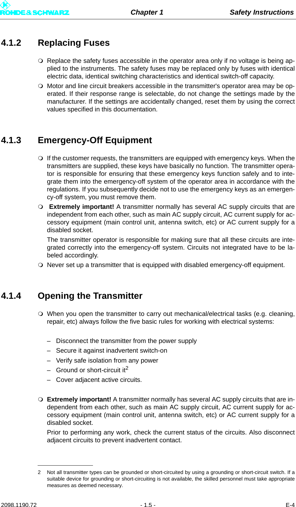


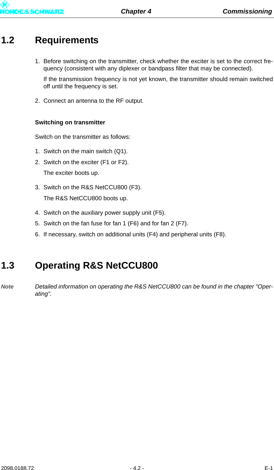
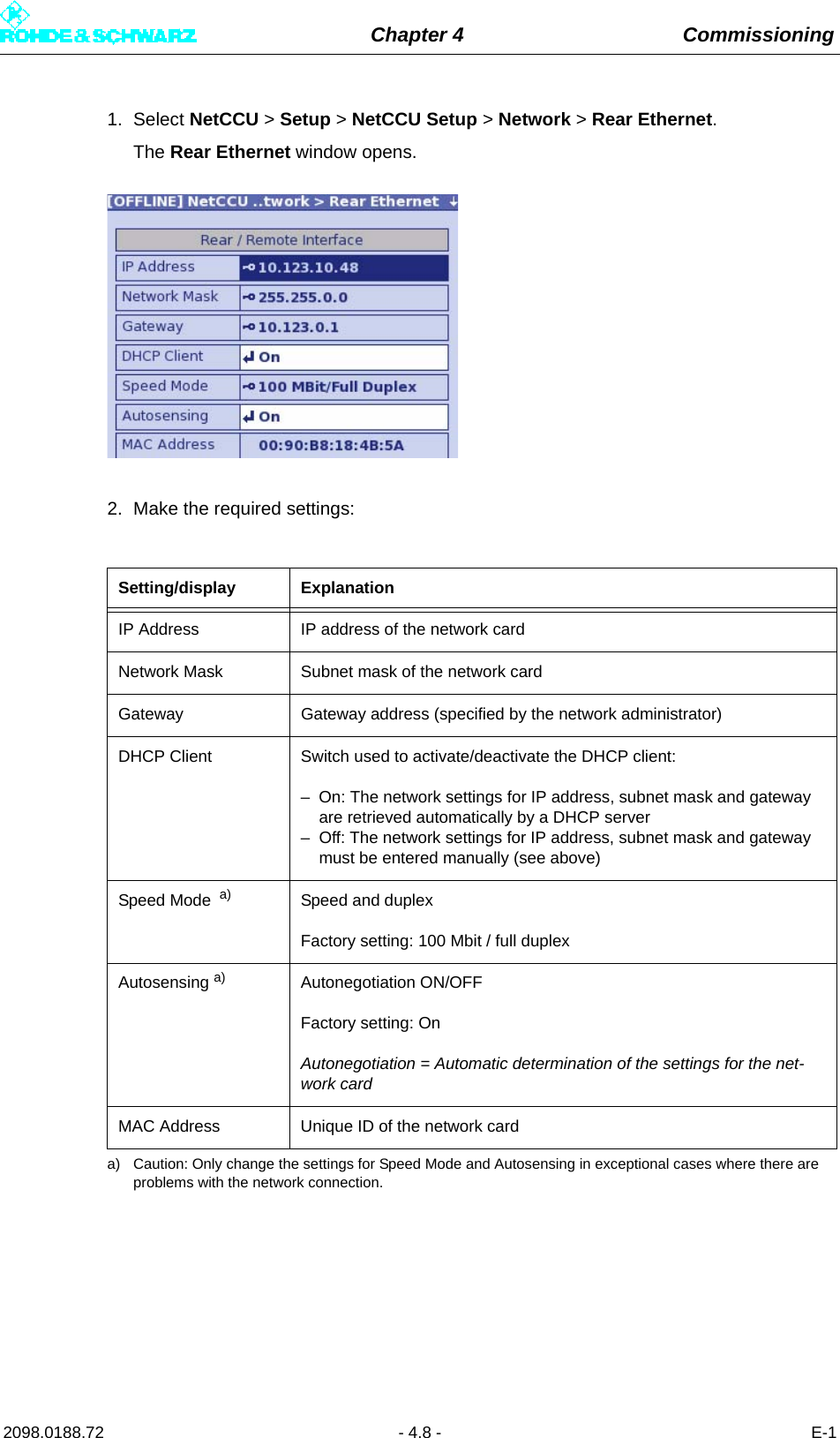
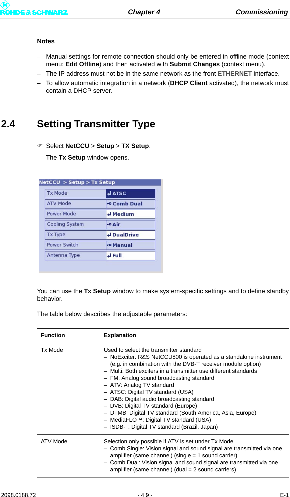
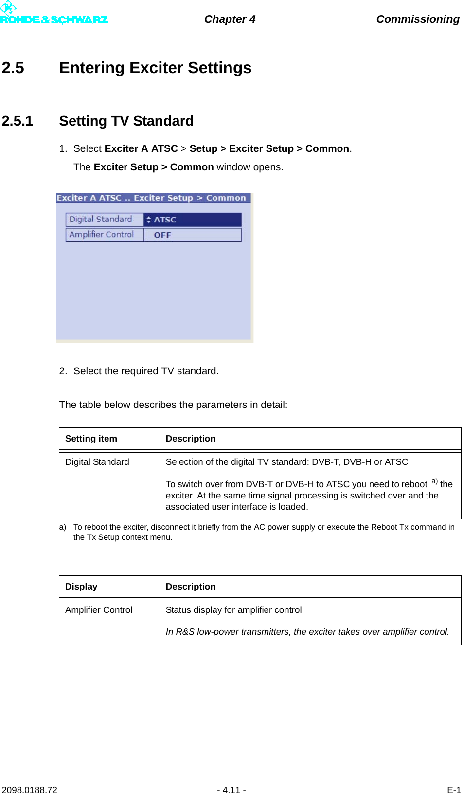
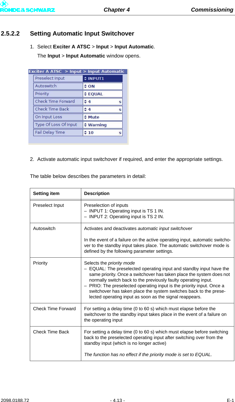
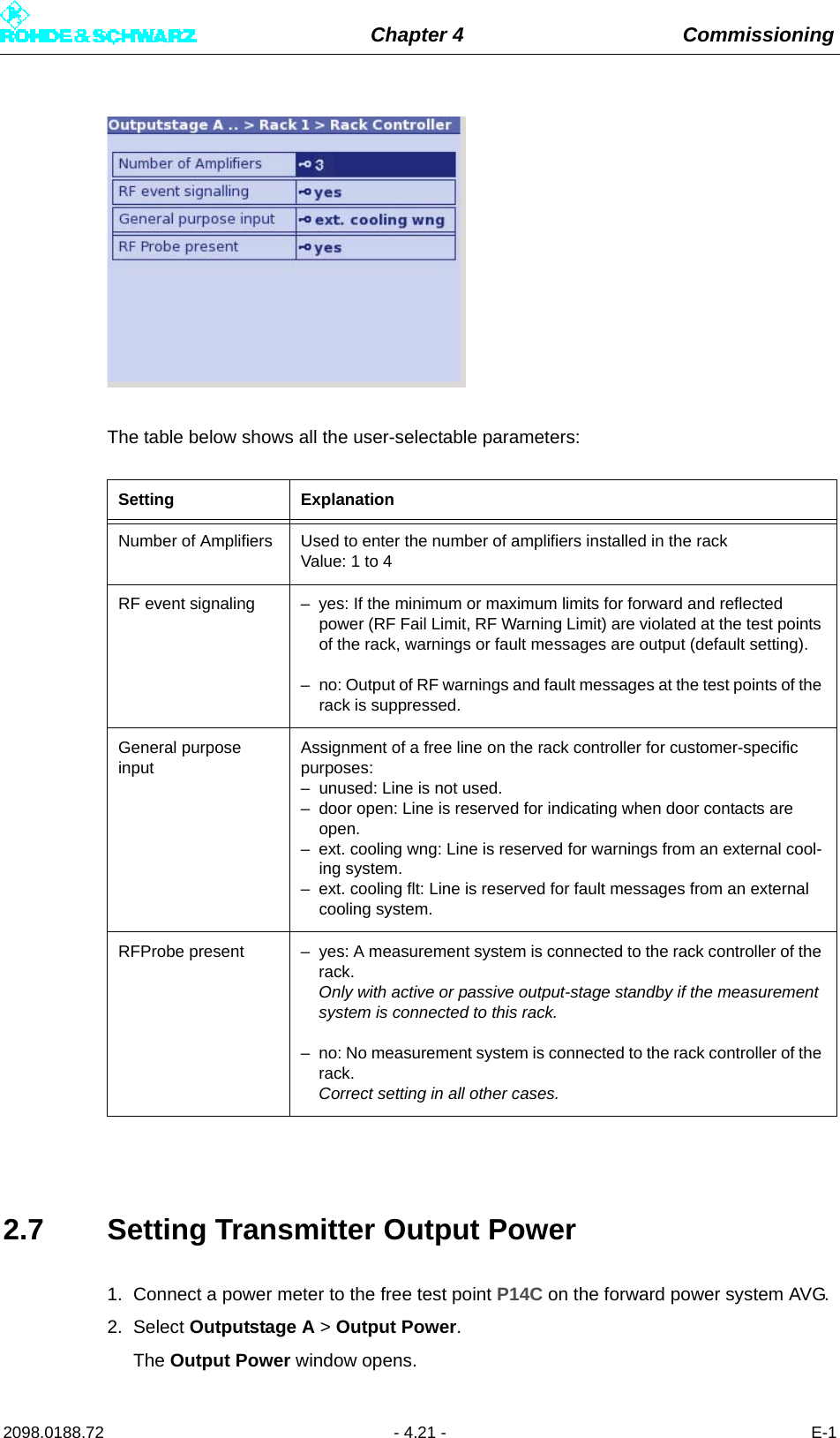
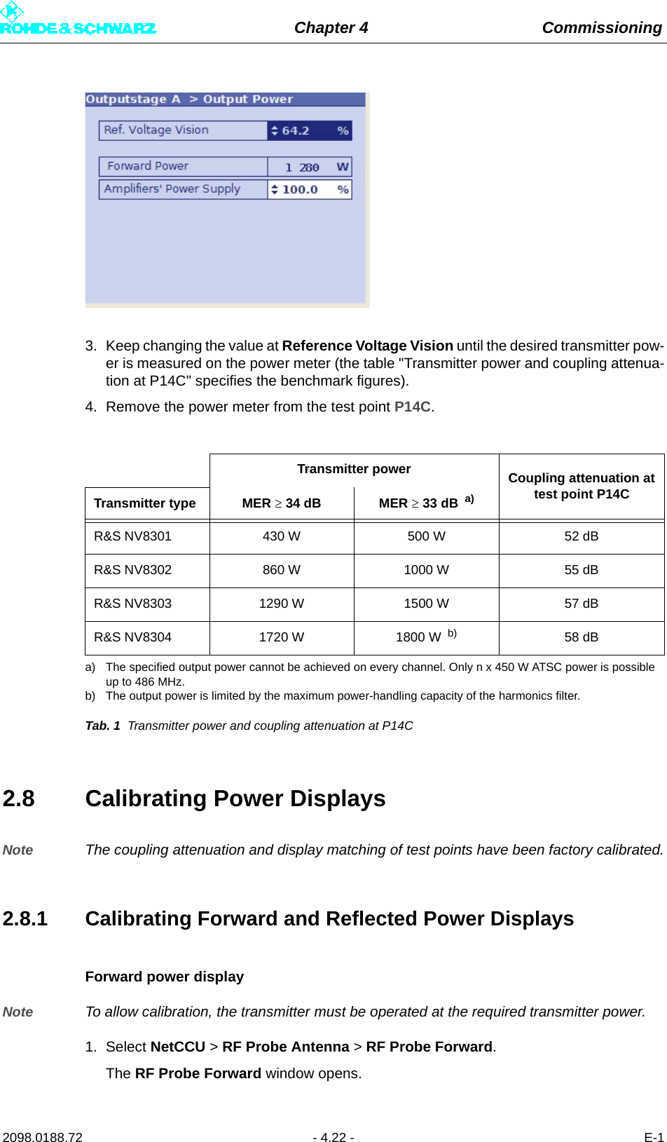
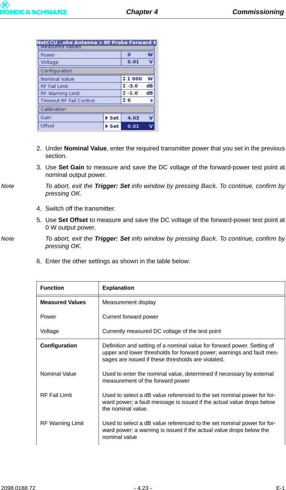
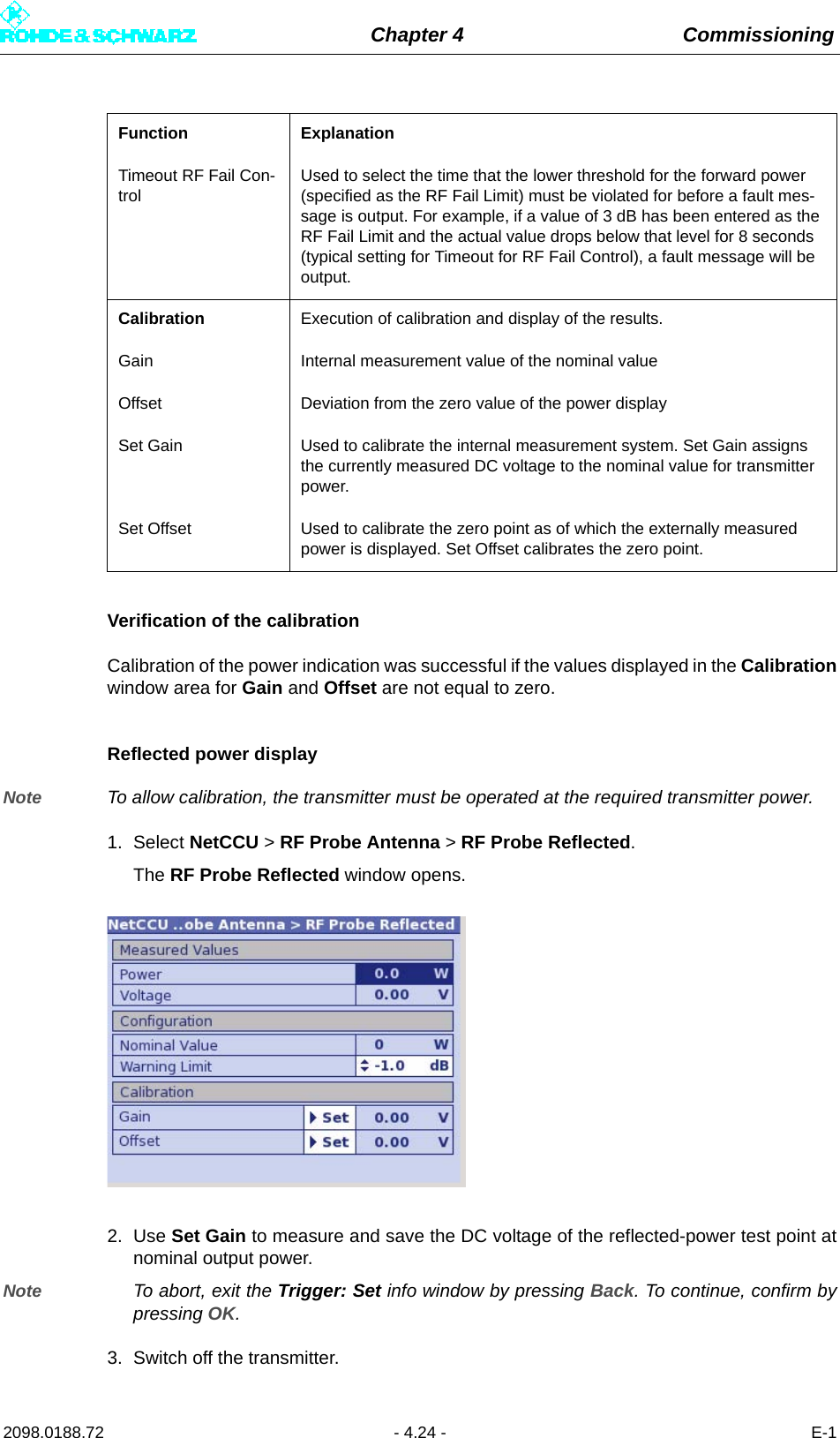
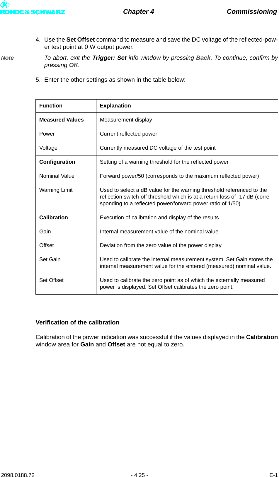
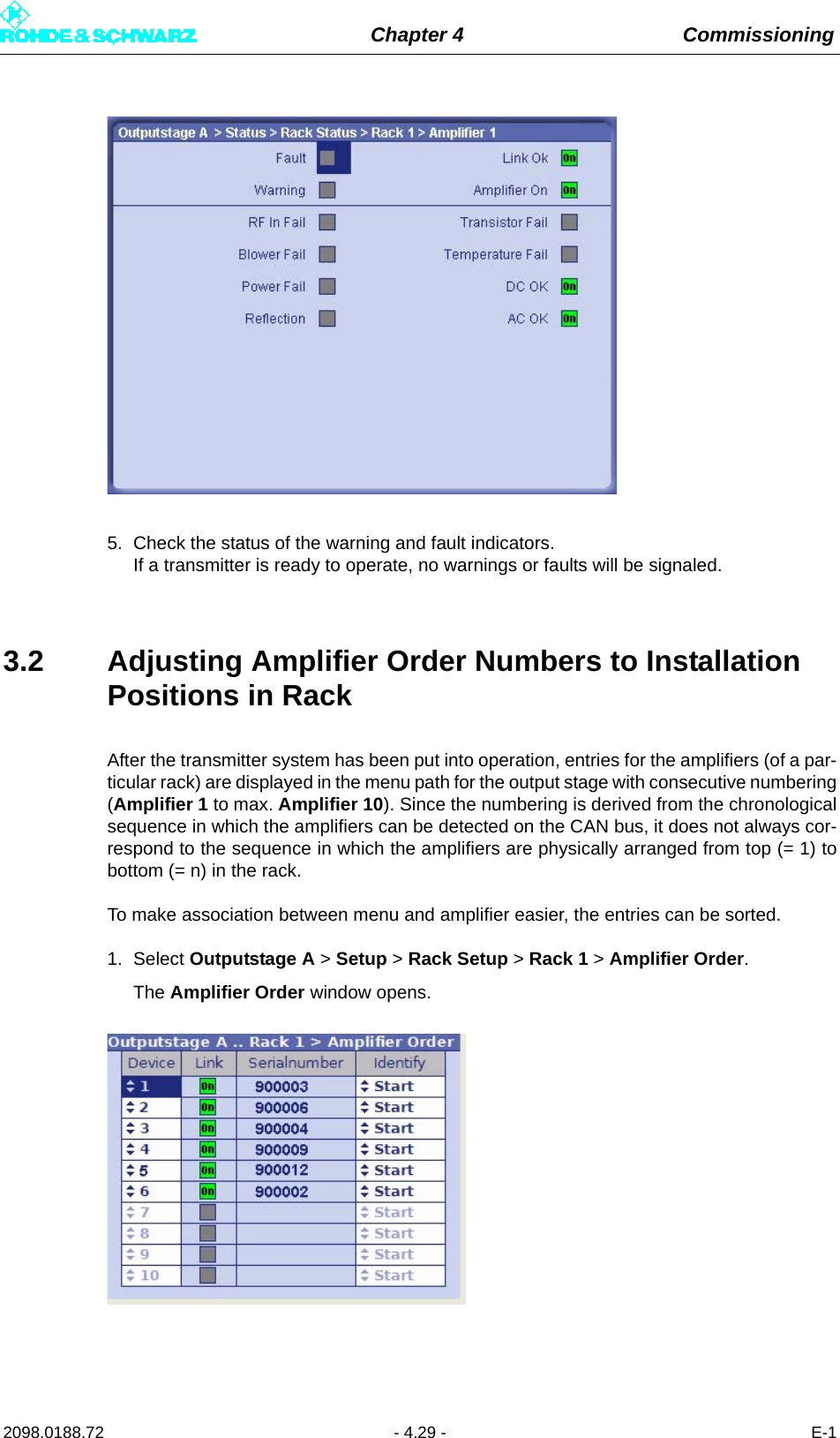
![Chapter 4 Commissioning2098.0188.72 - 4.12 - E-12.5.2 Configuring Input Interfaces2.5.2.1 Specifying Data Format for Data Streams Input 1 and Input 21. Select Exciter A ATSC > Input > Input Config.The Input > Input Config window opens.2. Go to Presel. Mode and select the value Auto for Input1 and Input2.The data format is recognized automatically.The table below describes the parameters in detail:Setting item ExplanationPresel. Mode[Input 1/Input 2]Sets the data format for the two data streams (main and standby sig-nals) on inputs TS 1 IN or TS 2 IN.The options are as follows:– AUTO: The data format is recognized automatically– ASI: Manual setting for an ASI transport stream– SMPTE: Manual setting for an SMPTE transport streamDisplay ExplanationPacket Length[Input 1/Input 2]Displays the packet length detected at the respective inputMeas.Data Rate [bps][Input 1/Input 2]Displays the data rate measured at the respective input without null packetsReq. Data Rate [bps][Input 1/Input 2]Display for checking the measured data rate. The maximum data pro-cessing rate is displayed.Active Mode Displays the data format detected or set at the respective input:– ASI: As described– SMTPE: As described– AUTO: Auto is selected and there is no data stream](https://usermanual.wiki/Rohde-and-Schwarz/NV830X.User-Manual-Part-1/User-Guide-1672826-Page-130.png)
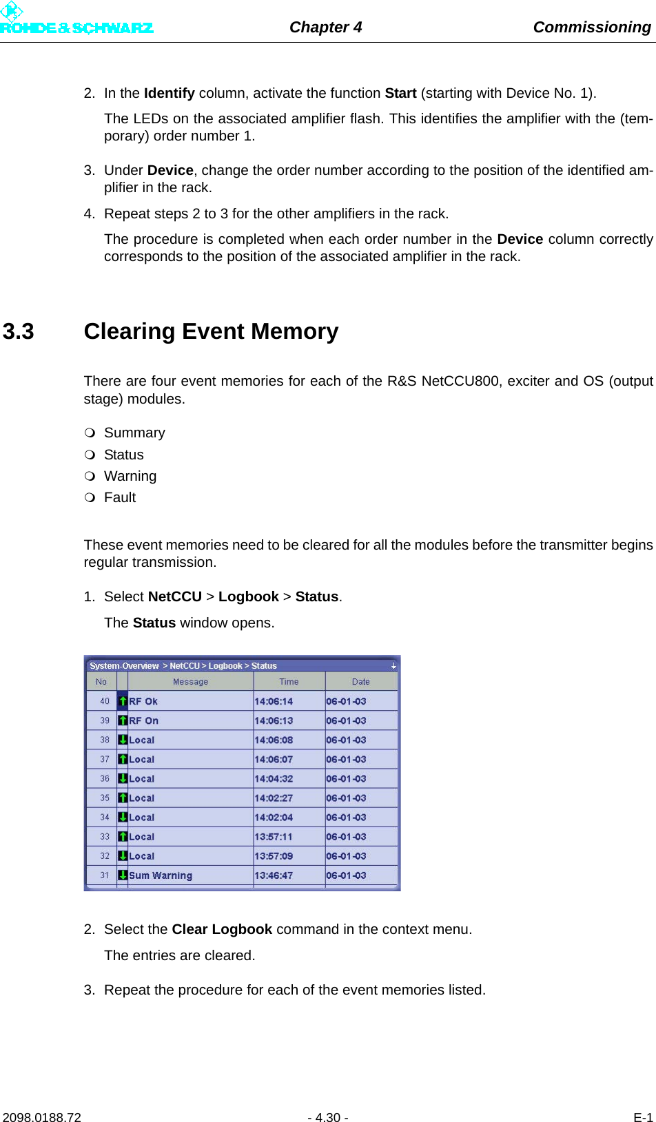
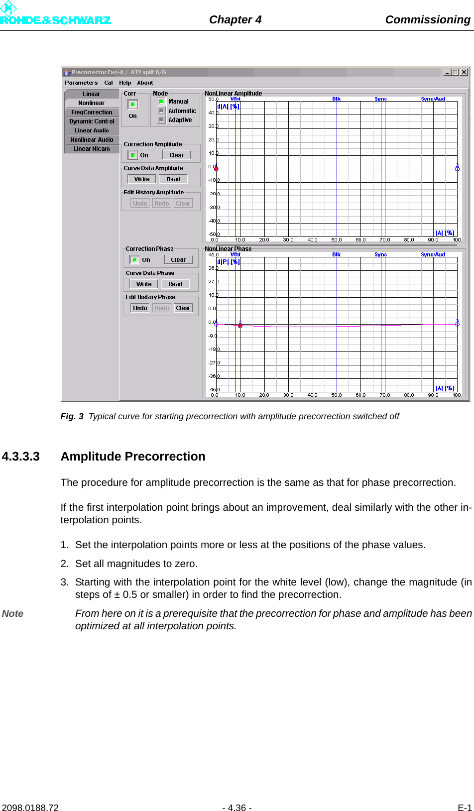
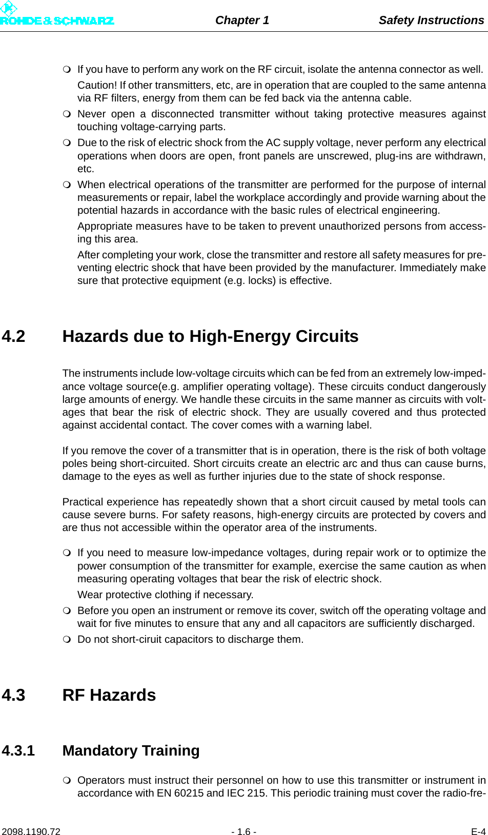
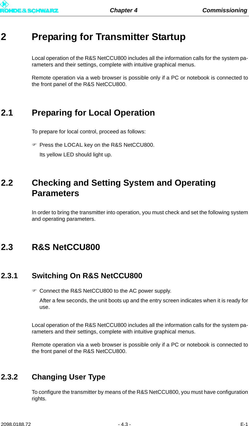
![Chapter 4 Commissioning2098.0188.72 - 4.31 - E-14 PrecorrectionThis section describes the non-linear precorrection sequence in manual mode.4.1 Functions of Nonlinear Precorrector4.1.1 GeneralIn the basic version, the graphical user interface of the non-linear precorrector for DTV andvideo signals consists of the Nonlinear control panel and the FreqCorrection control pan-el. In the case of ATV split, two further control panels are provided: Dynamic Control forthe video precorrector and Nonlinear Audio for the audio signal. In combined mode an au-dio phase precorrector is also provided for audio.4.1.2 Linear Basic PrecorrectionThe basic functions of the non-linear precorrector can be accessed via the Nonlinear andNonlinear Audio control panels. Additional functions can be performed in the other controlpanels.Every non-linear precorrector consists of an amplitude precorrector and a phase precorrec-tor, each independently affecting the phase distortion and amplitude distortion of the samesignal. The setting of the characteristic is displayed in a graphic in which the X axis repre-sents the instantaneous signal amplitude. The figures 0% and 100% stand for no signal am-plitude and maximum amplitude respectively. The Y axis represent the effect and is scaledto ±50 % for amplitude precorrection and ±45° for phase precorrection. 50% means that at100% amplitude the level is increased by 3 dB.Every precorrector has a series of frequency reference points which are used to model thecharacteristic. Frequency reference points can be user-defined, shifted in the X and Y di-rections, be given a fixed or free slope and be deleted. In the X direction a frequency refer-ence point can only be shifted between the two adjacent reference points. The connectionsbetween frequency reference points are computed by means of spline functions.Every characteristic consists of at least two points, one of which must be at 0% and the oth-er at 100%.In the case of amplitude precorrection the first point is at [0%, 0%] and cannot be shifted.The second point is at 100% and can be shifted without restriction in the Y direction. A risingor falling straight line between the two points represents only an amplification or attenuationof the signal and does not create non-linear products.In the case of phase precorrection the first point is at 0% and the second point is at 100%.Both points can be shifted without restriction in the Y direction. A straight line parallel to theamplitude axis creates only a signal phase shift and does not create non-linear products.](https://usermanual.wiki/Rohde-and-Schwarz/NV830X.User-Manual-Part-1/User-Guide-1672826-Page-149.png)