Rohde and Schwarz NV830X UHF 1.8kW maximum Digital TV transmitter User Manual 32 SLX8000 12 12 07 01 00
Rohde & Schwarz Inc UHF 1.8kW maximum Digital TV transmitter 32 SLX8000 12 12 07 01 00
Contents
- 1. User Manual Part 1
- 2. User Manual Part 2
- 3. User Manual Part 3
User Manual Part 2
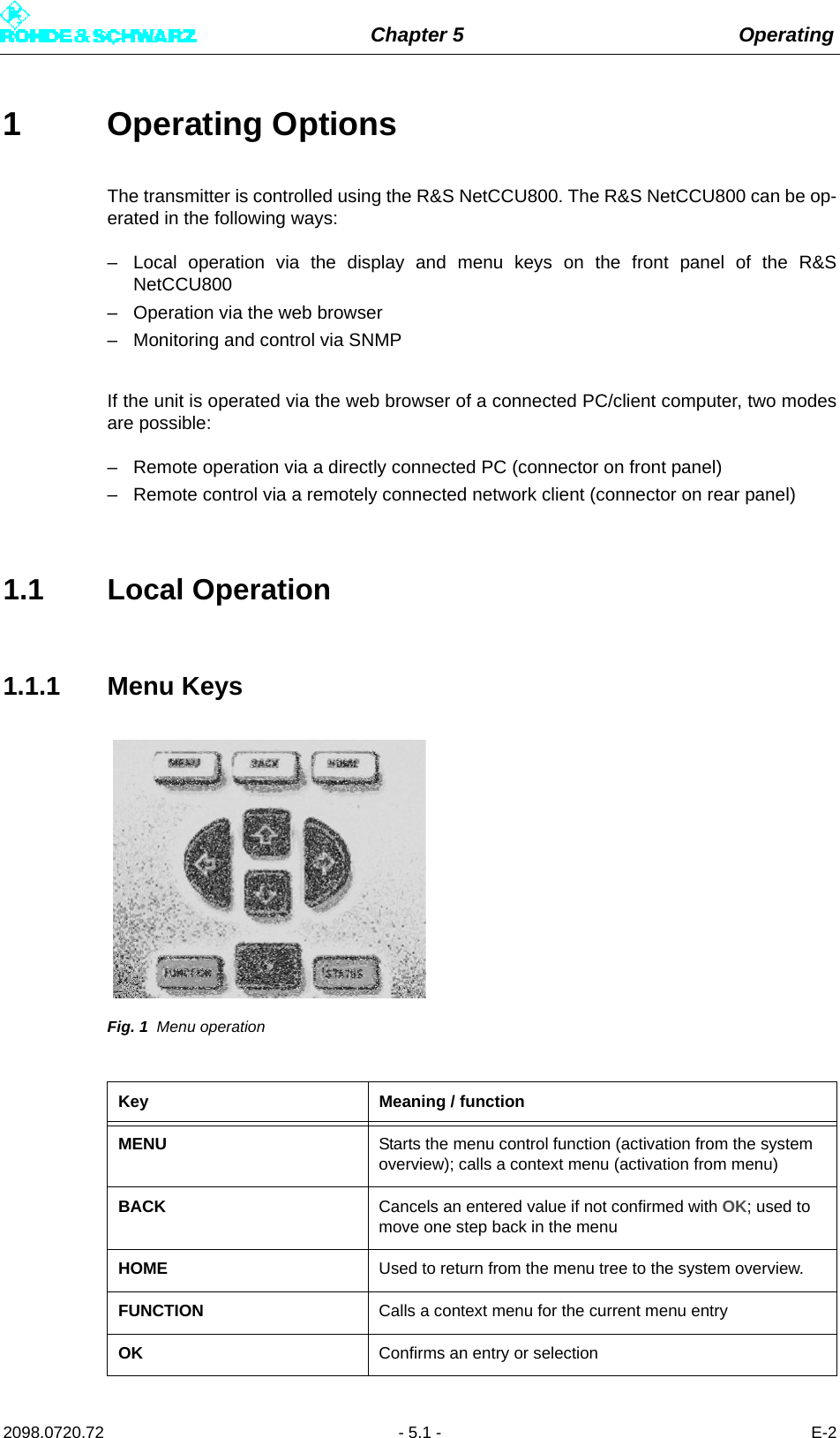
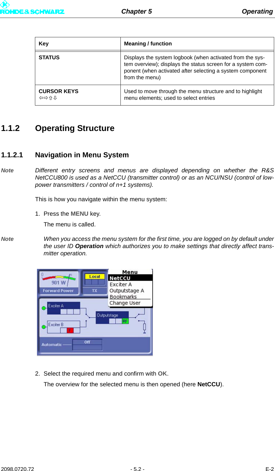
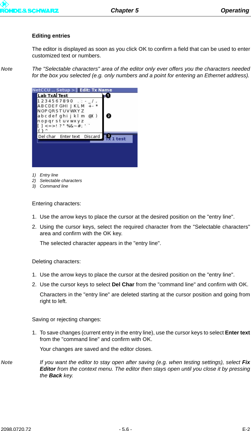
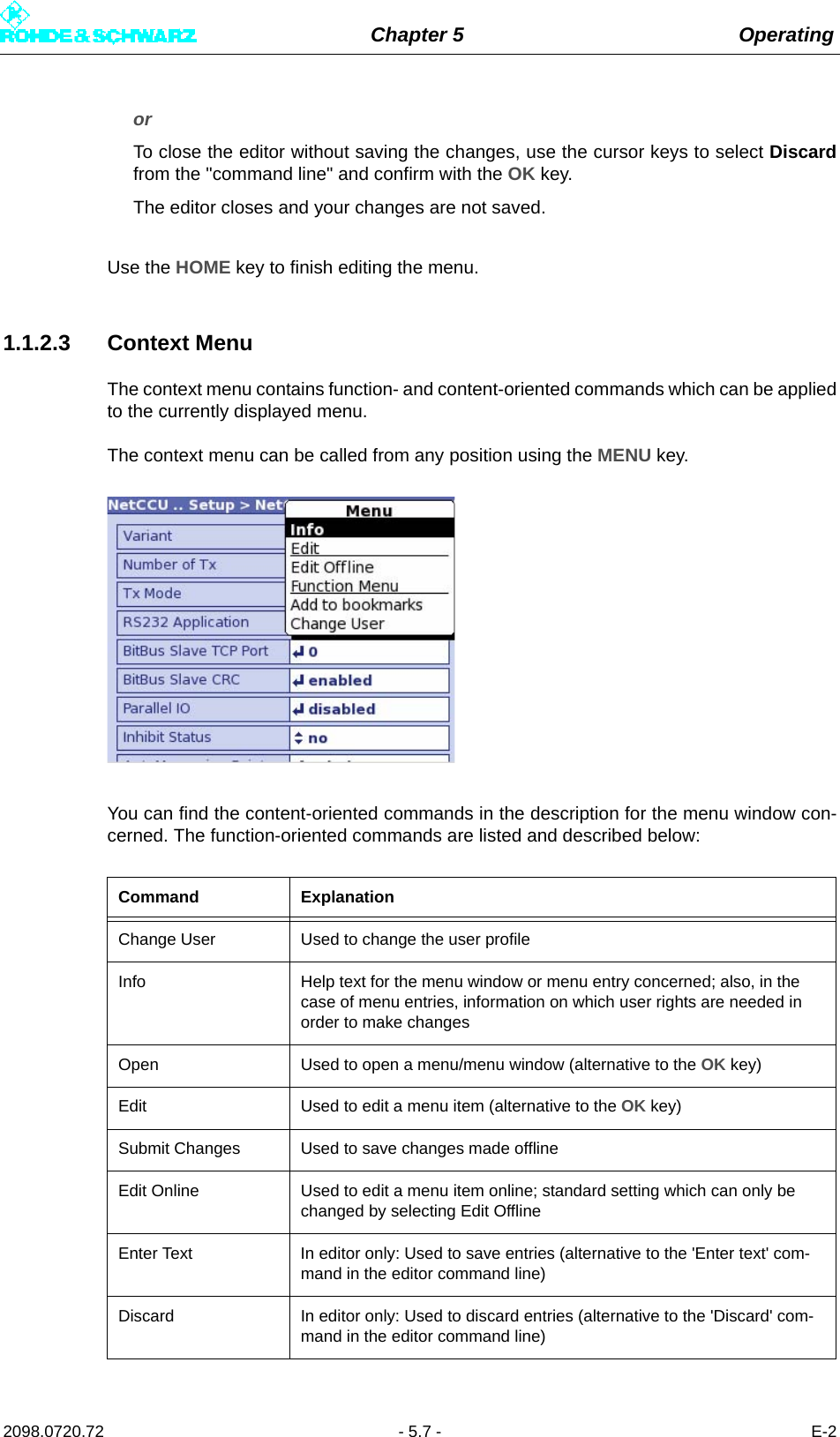
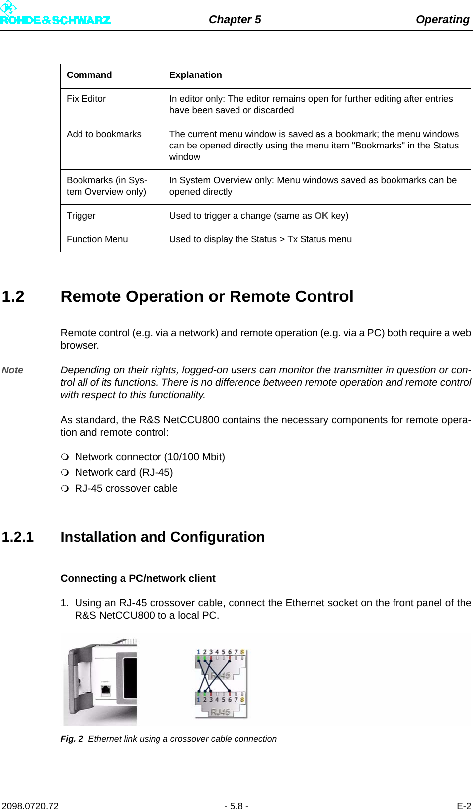
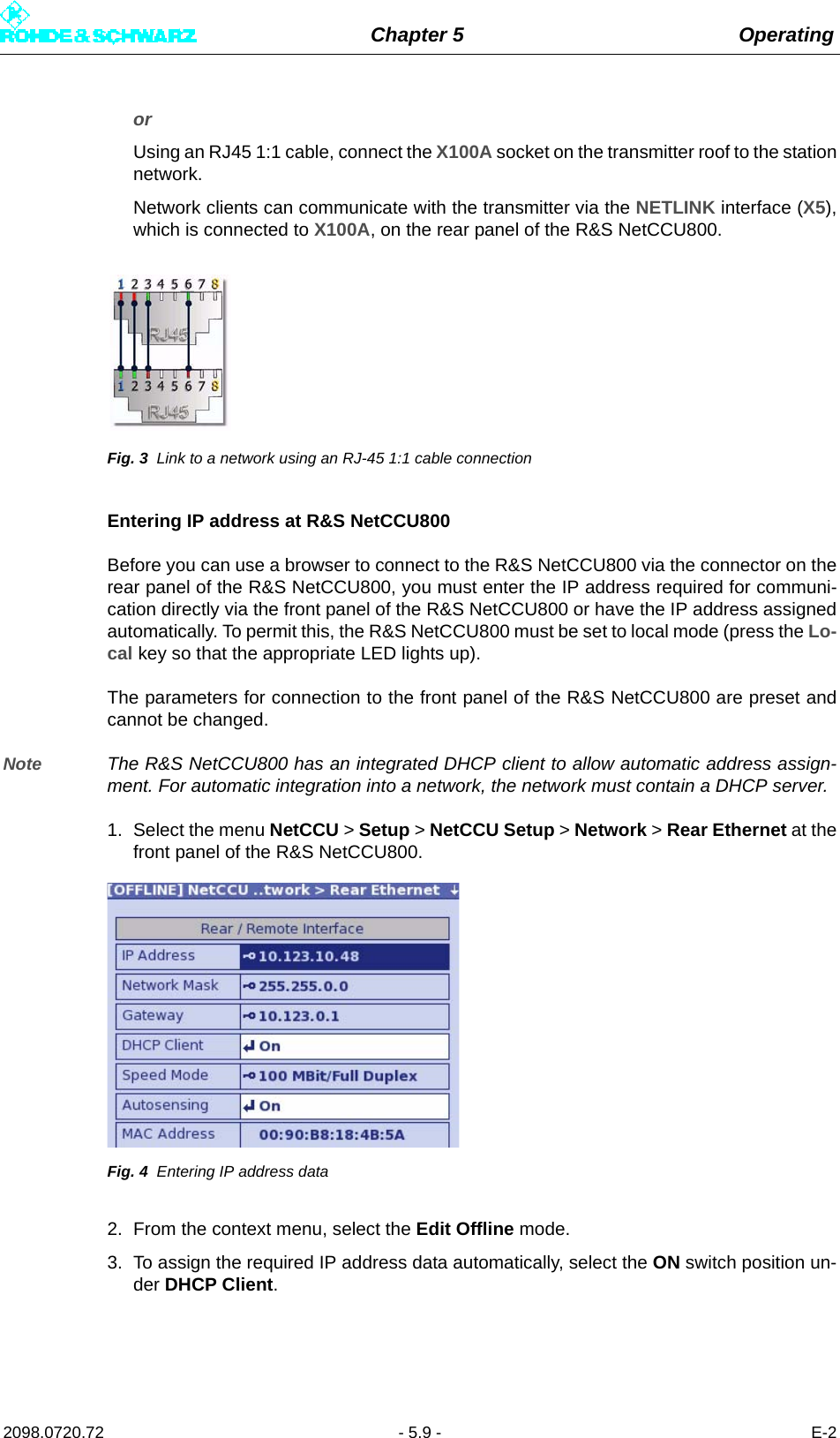
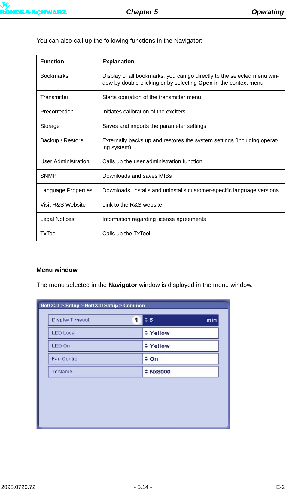
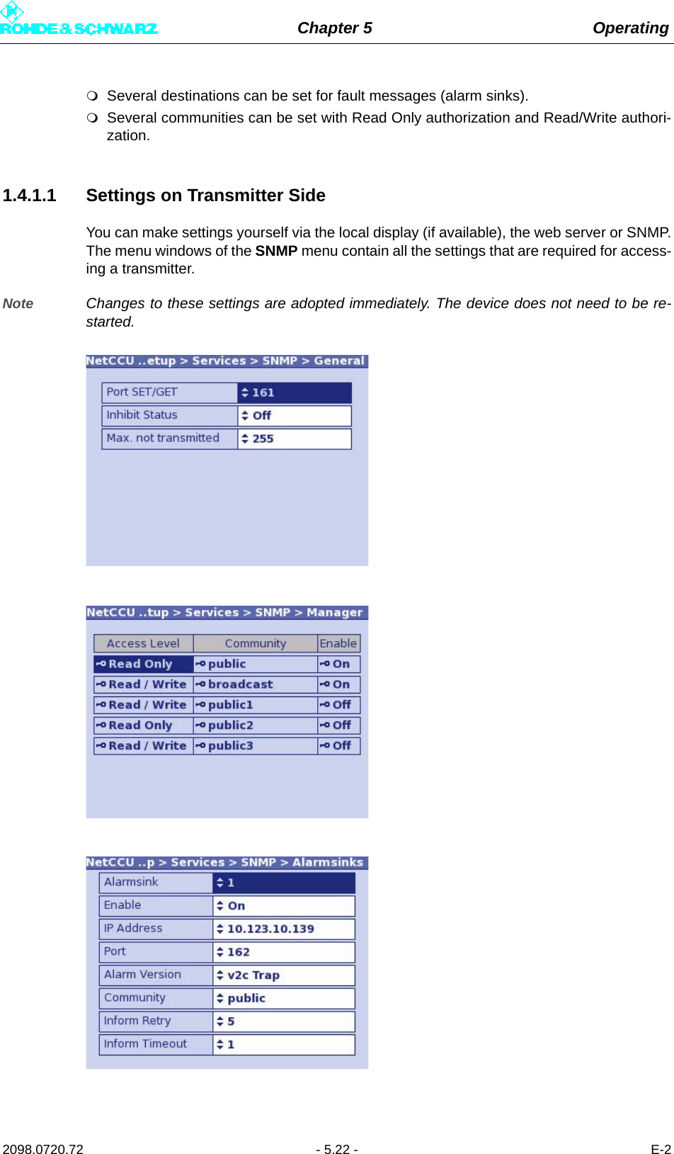
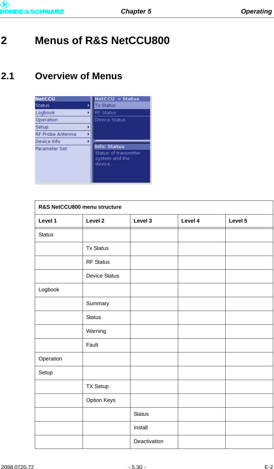
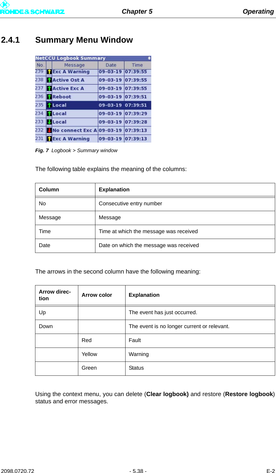
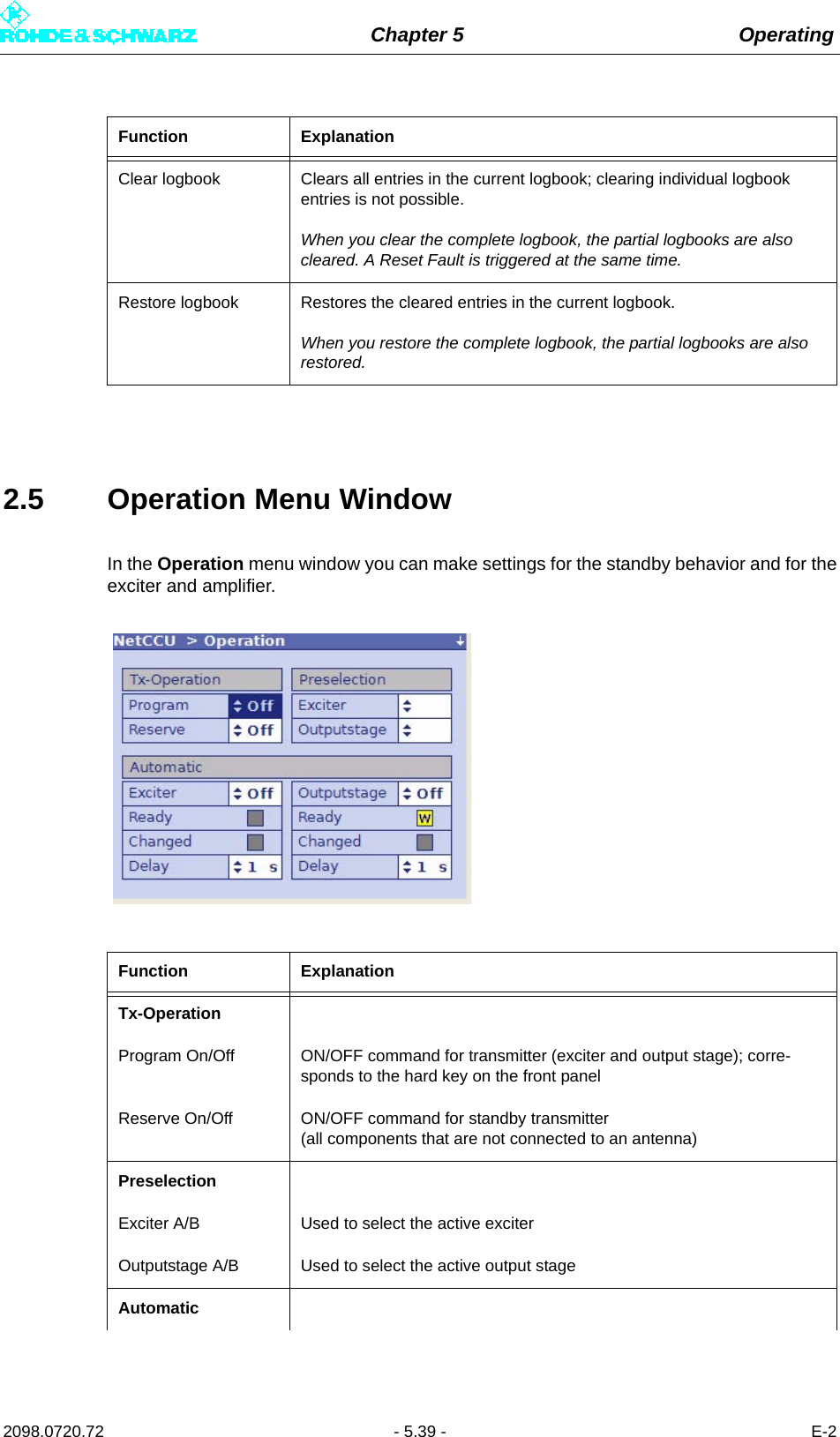
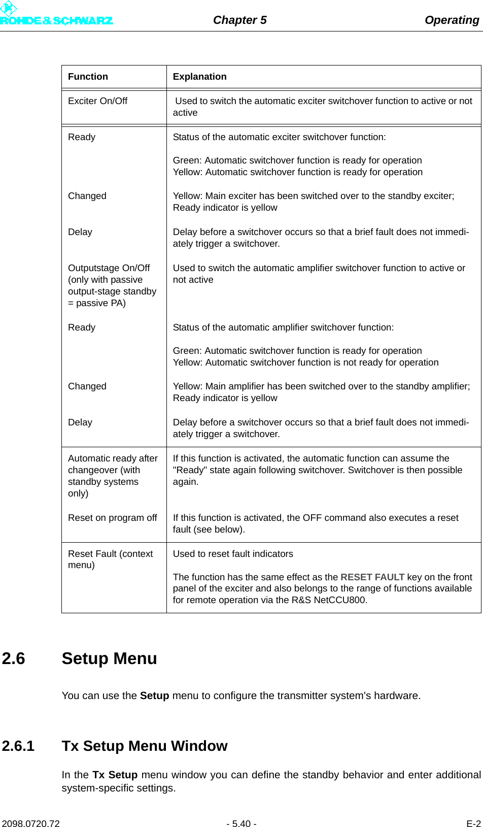
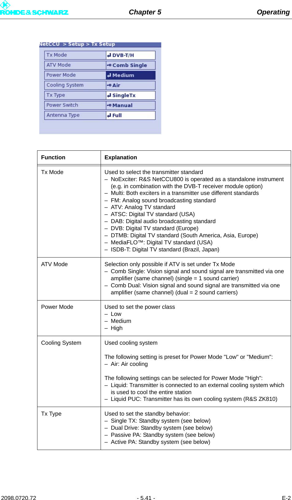
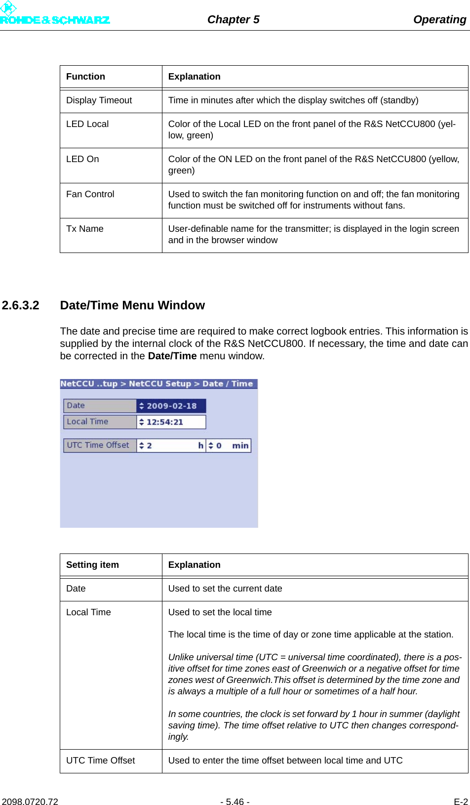
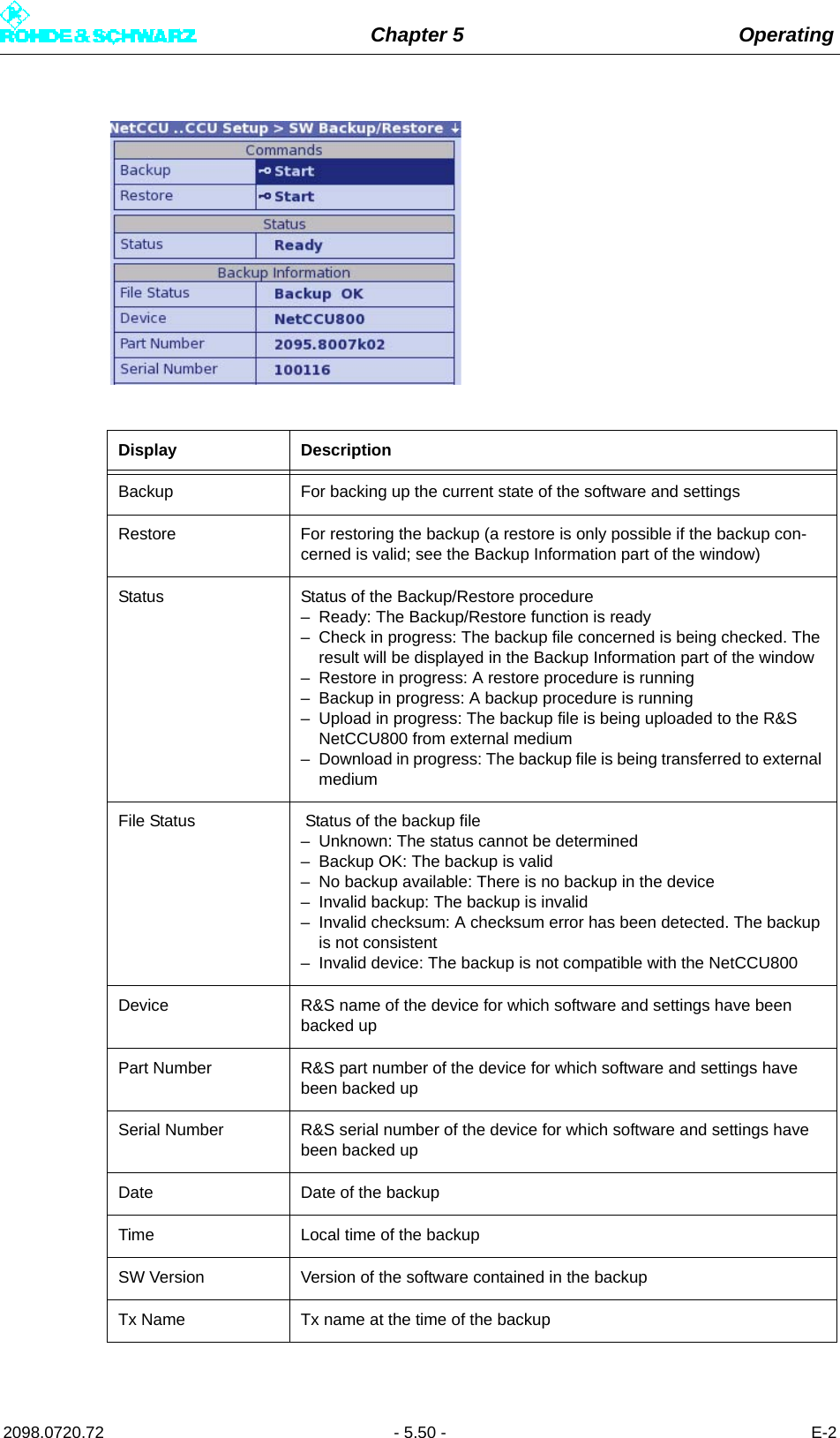
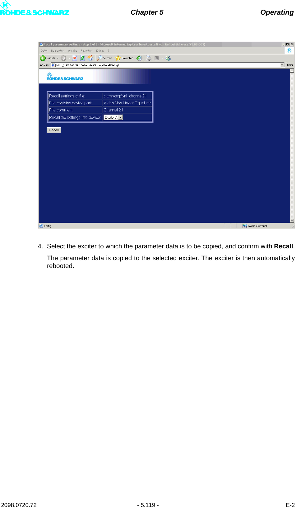
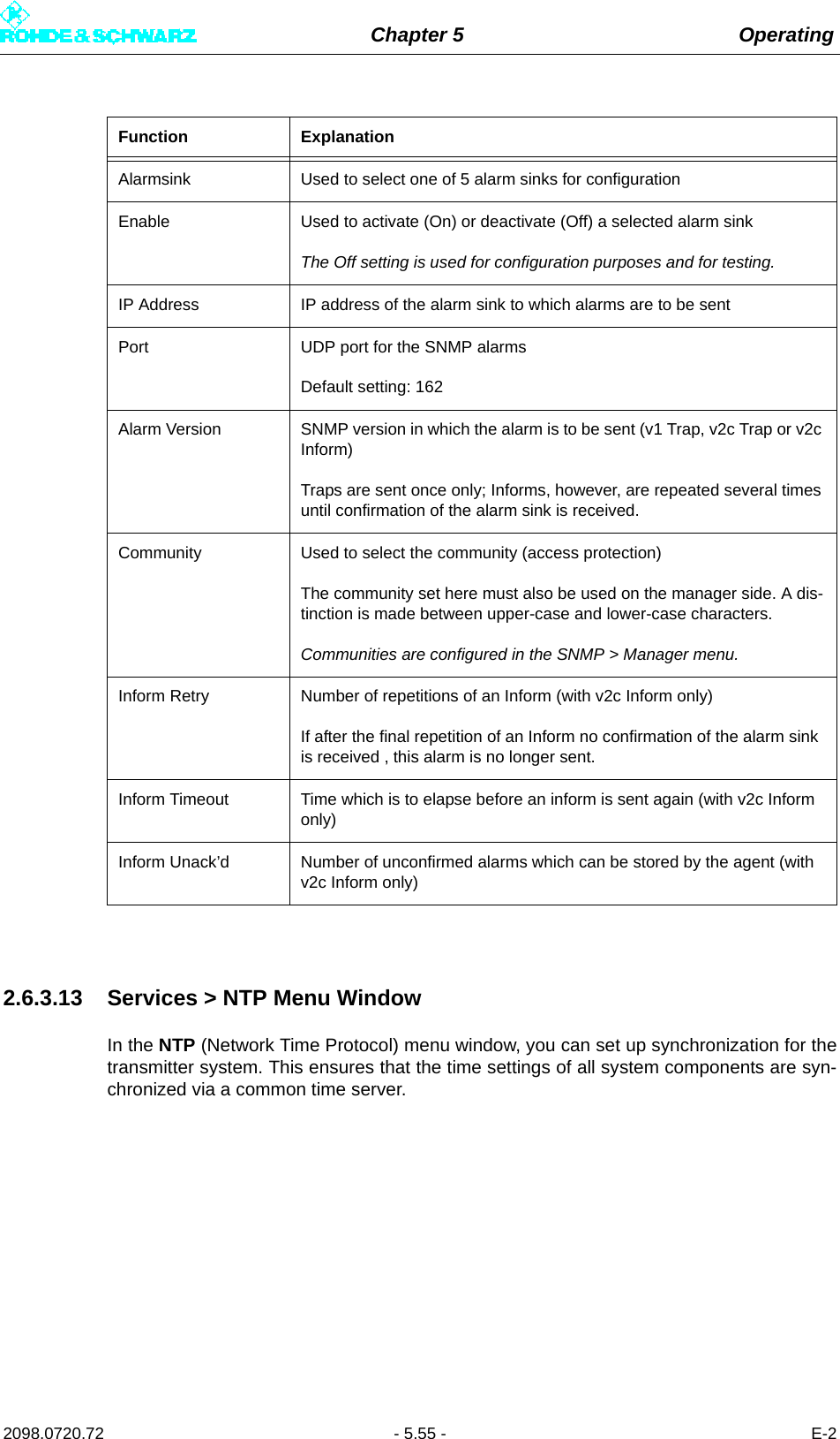
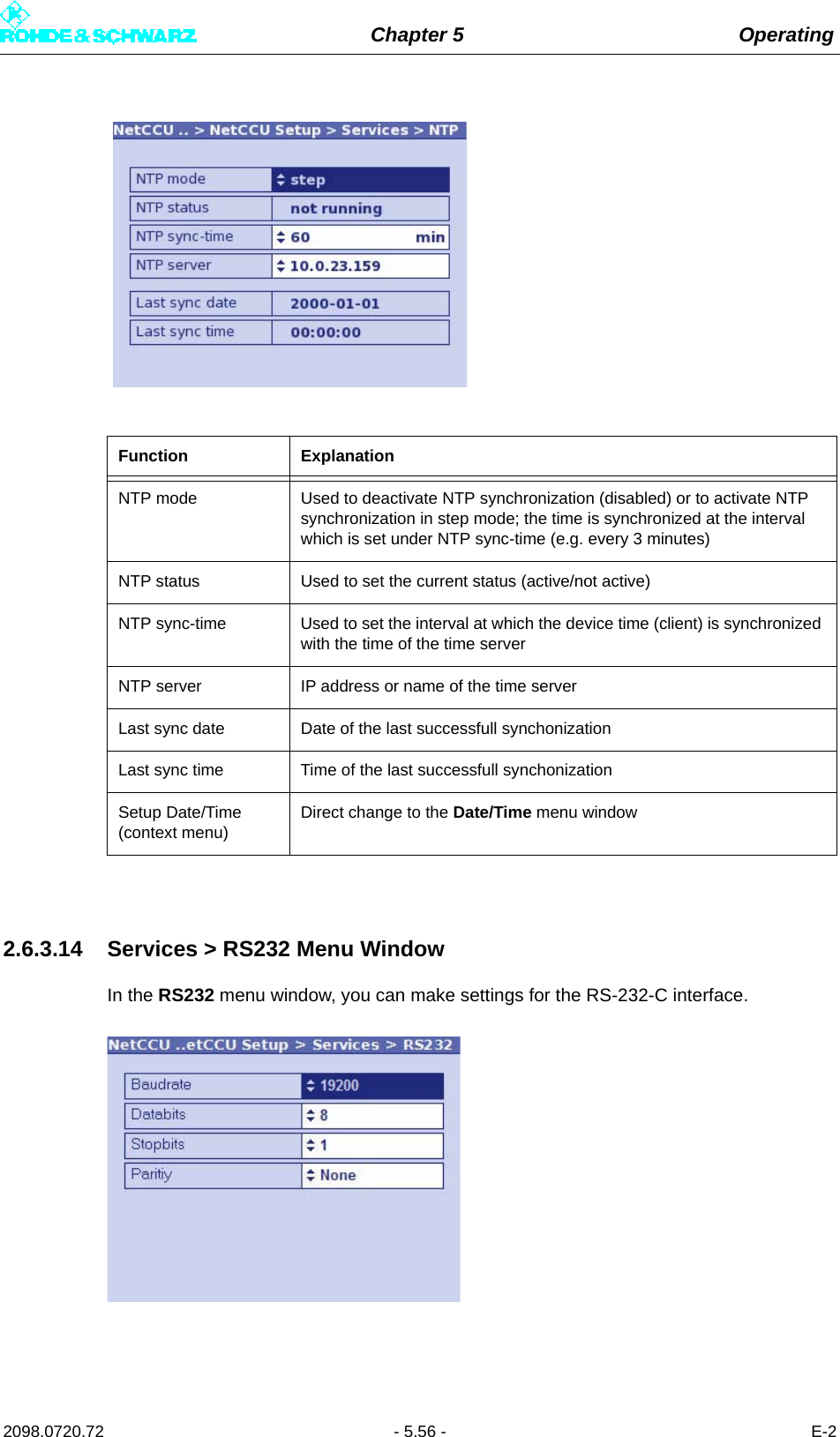
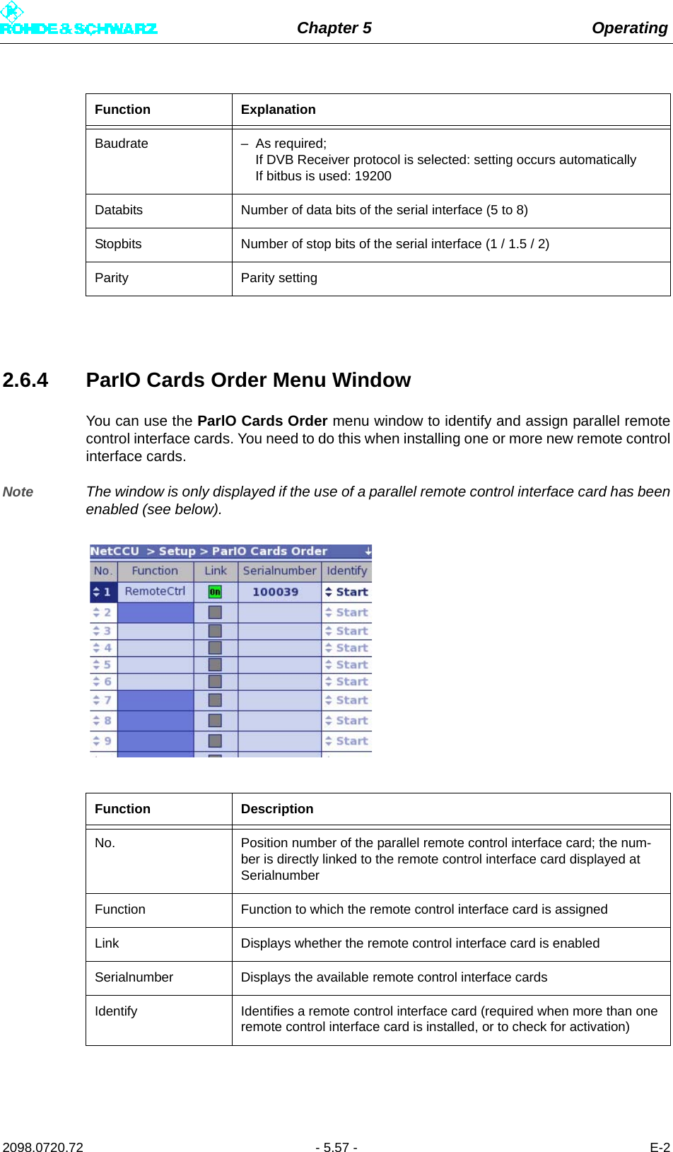
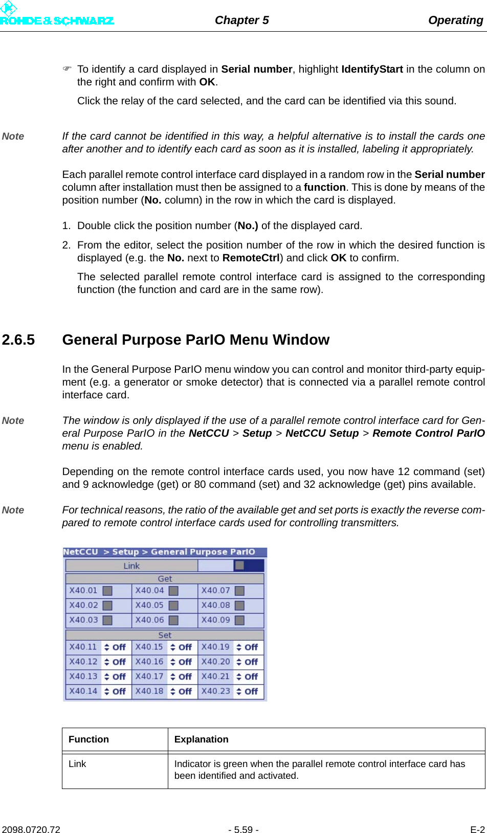
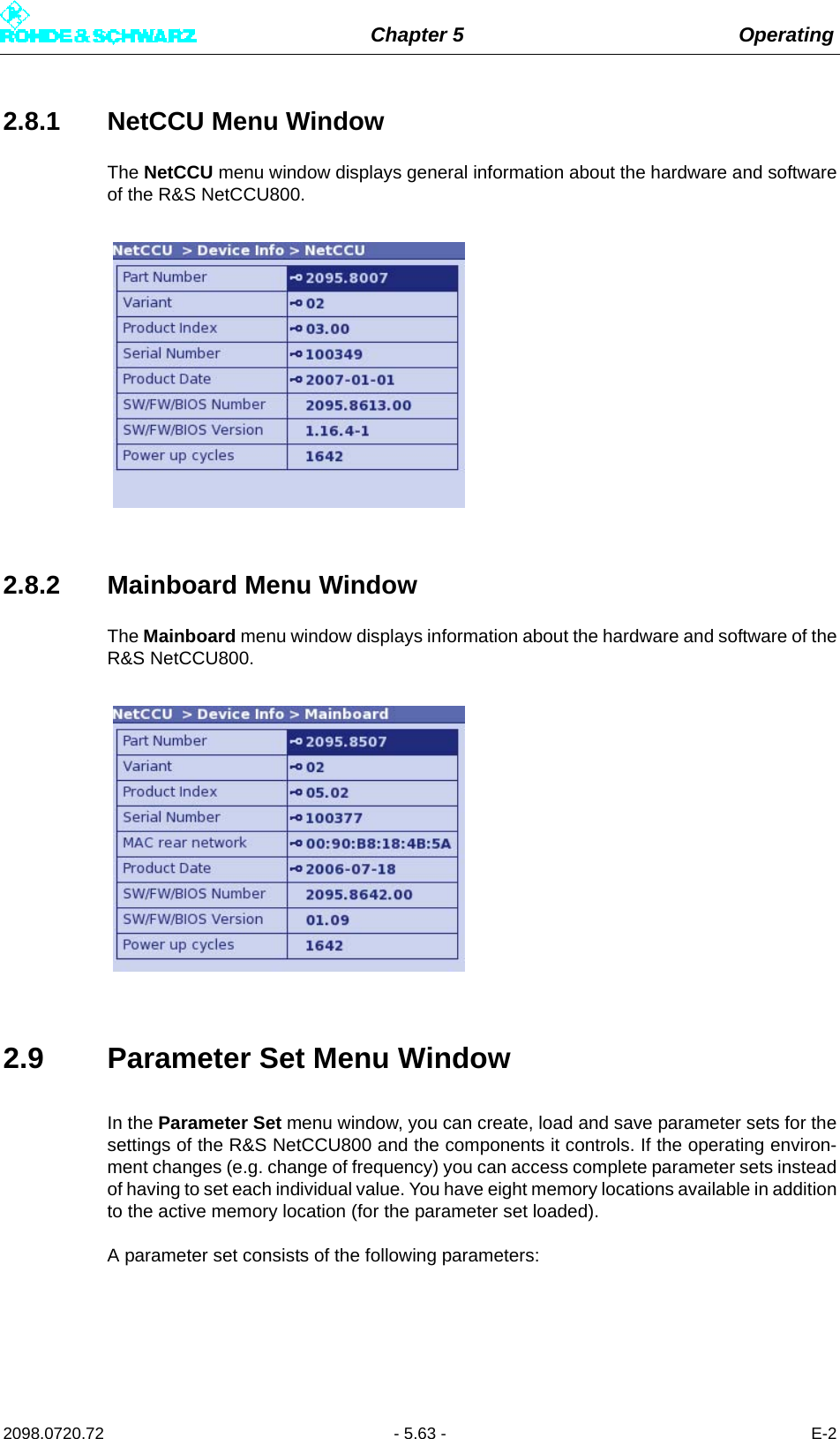
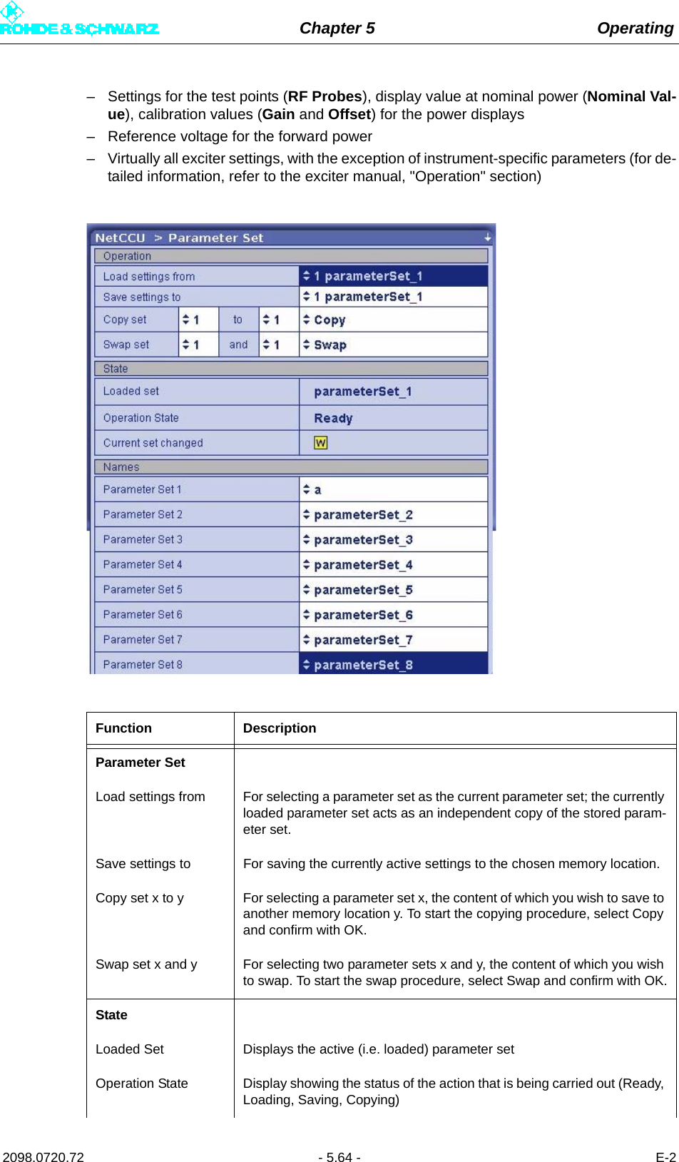
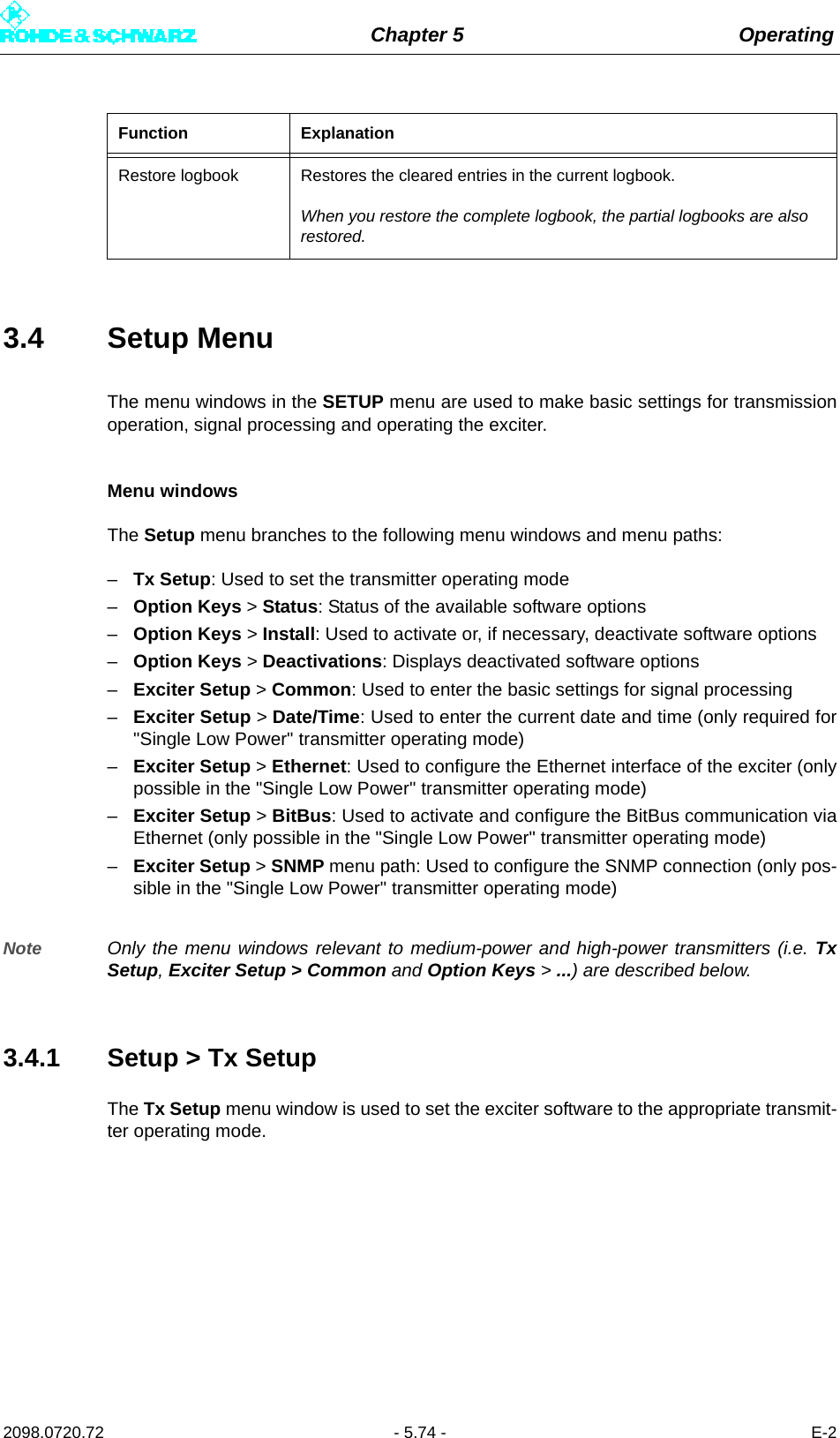
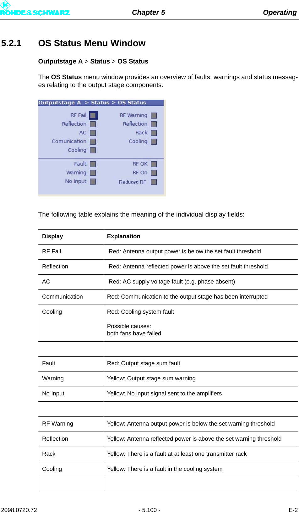
![Chapter 5 Operating2098.0720.72 - 5.54 - E-22.6.3.11 Services > SNMP > Manager Menu Window2.6.3.12 Services > SNMP > Alarmsinks Menu WindowFunction ExplanationAccess Level [1 … 5] Used to select access authorization for one of five user groups– Read Only: For GET (only read access to the agent)– Read / Write: For SET (read and write access to the agent)Community [1 … 5] Used to set the SNMP community string (a type of password) for a user groupDefault setting: "public" for read only (GET) and "broadcast" for read / write (SET)Case-sensitive!Enable Used to activate (On) or deactivate (Off) a communityThe Off setting is used for configuration purposes and for testing.](https://usermanual.wiki/Rohde-and-Schwarz/NV830X.User-Manual-Part-2/User-Guide-1672827-Page-60.png)
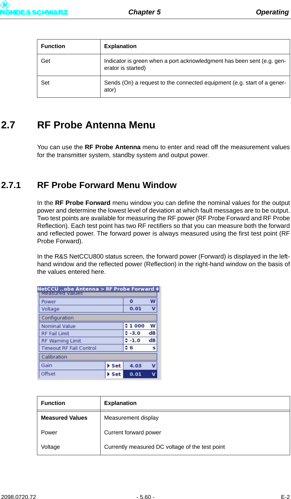
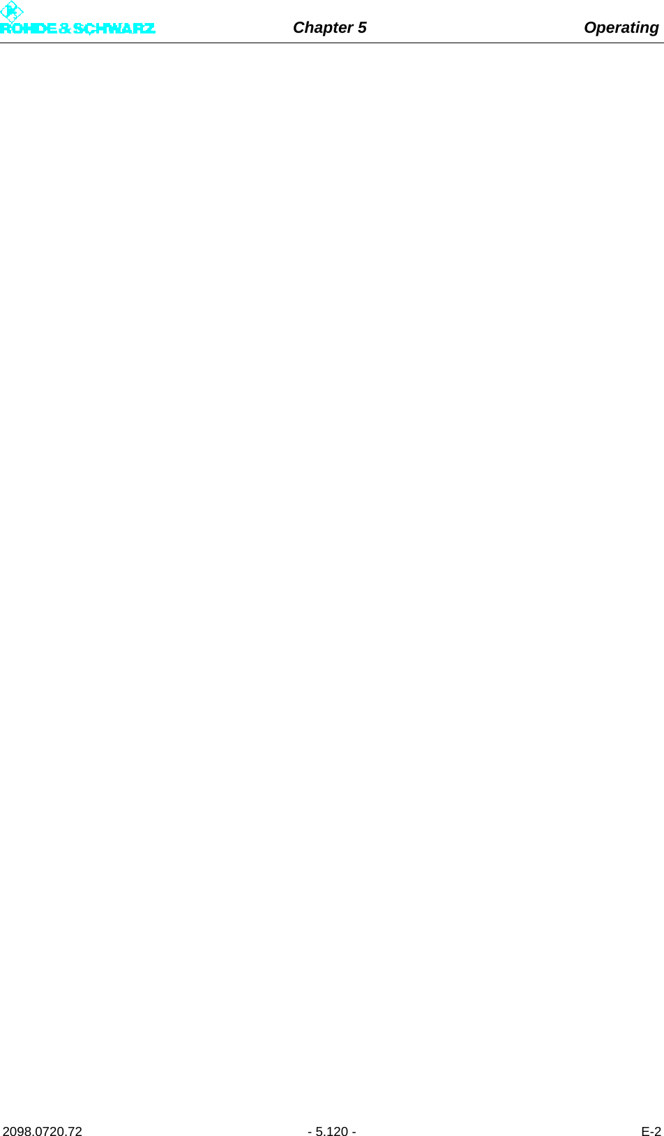
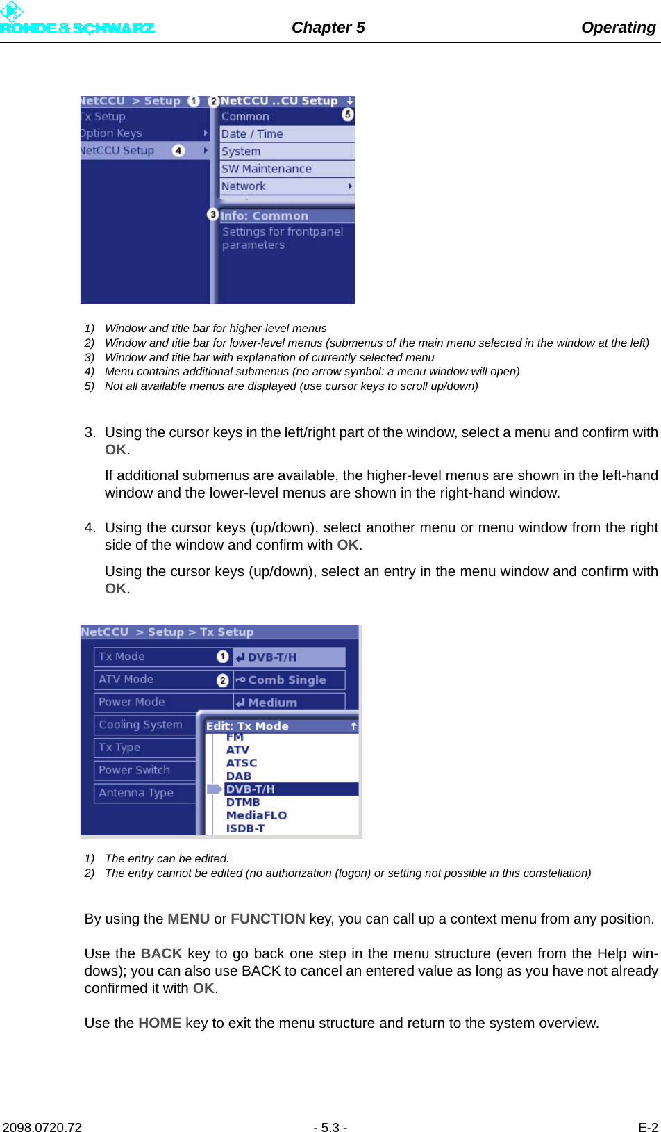
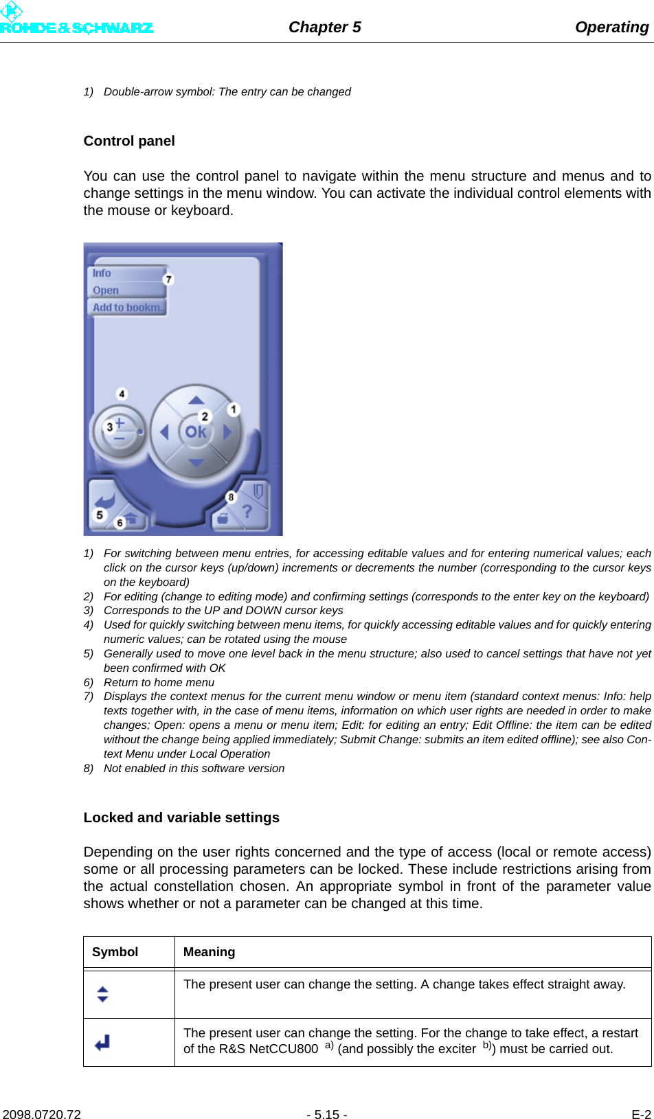
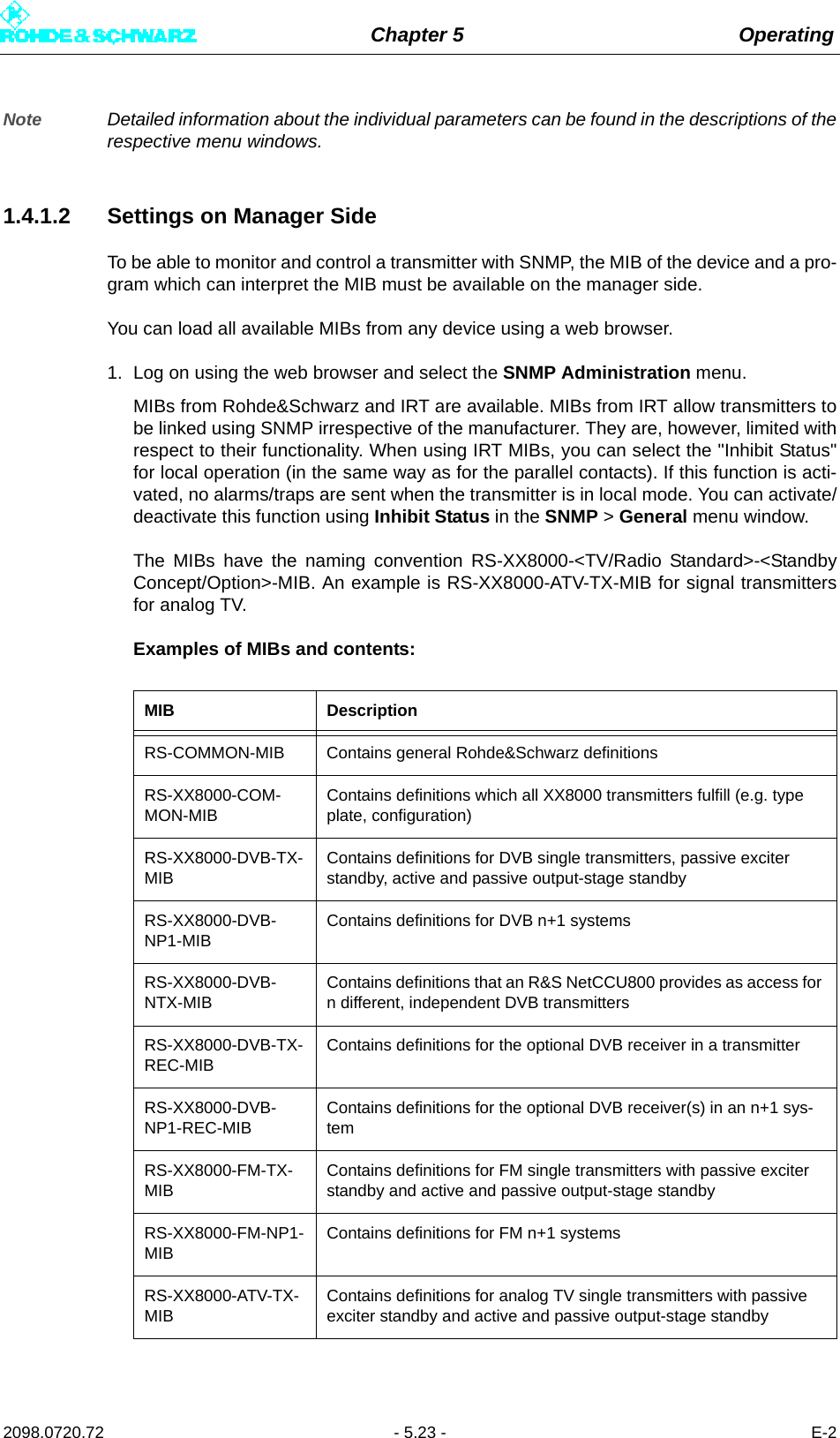
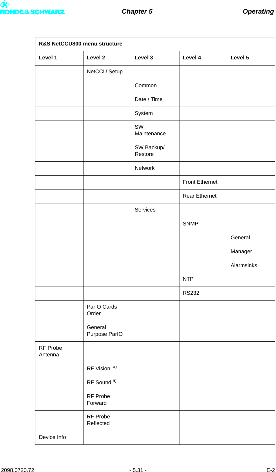
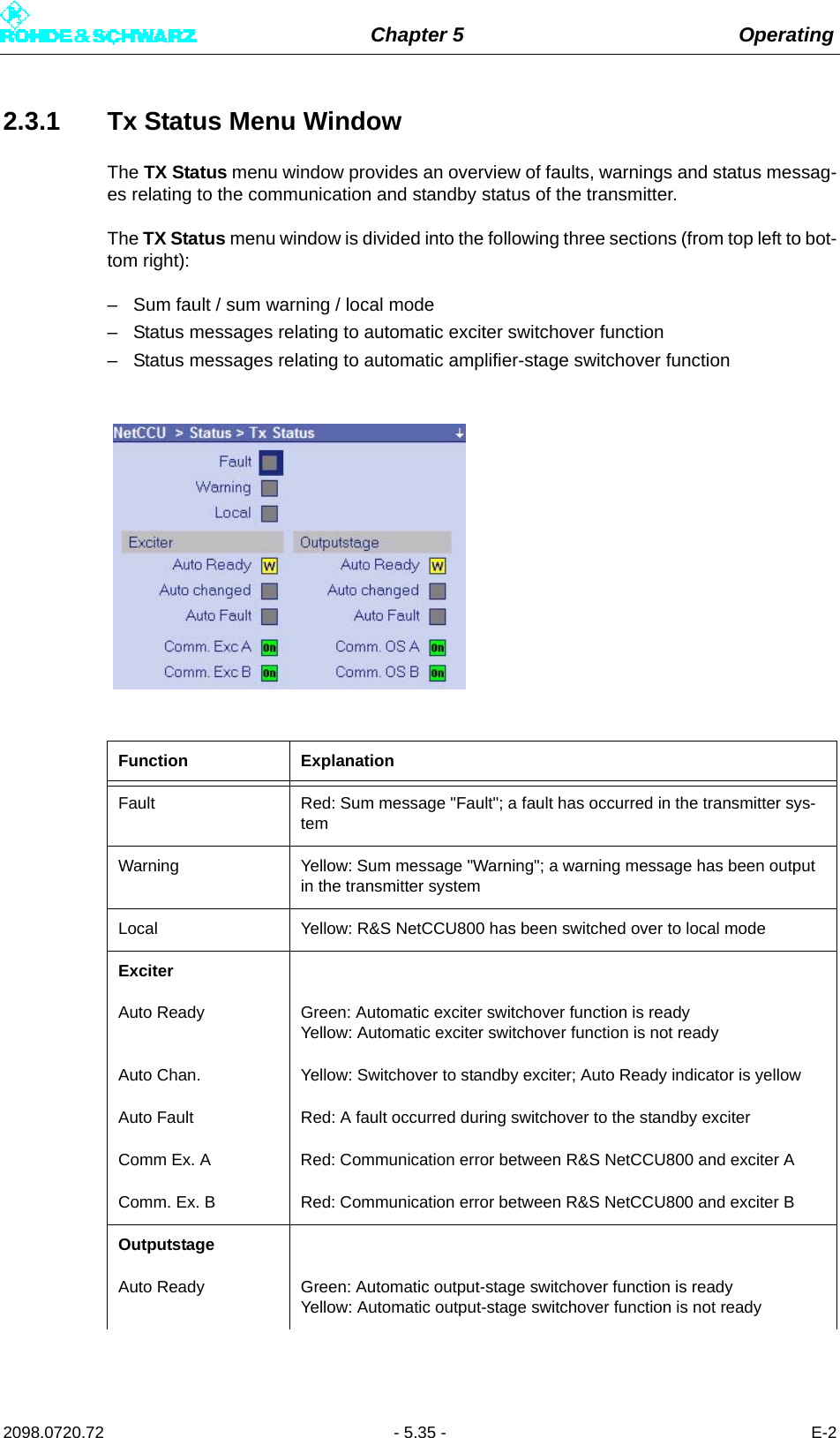
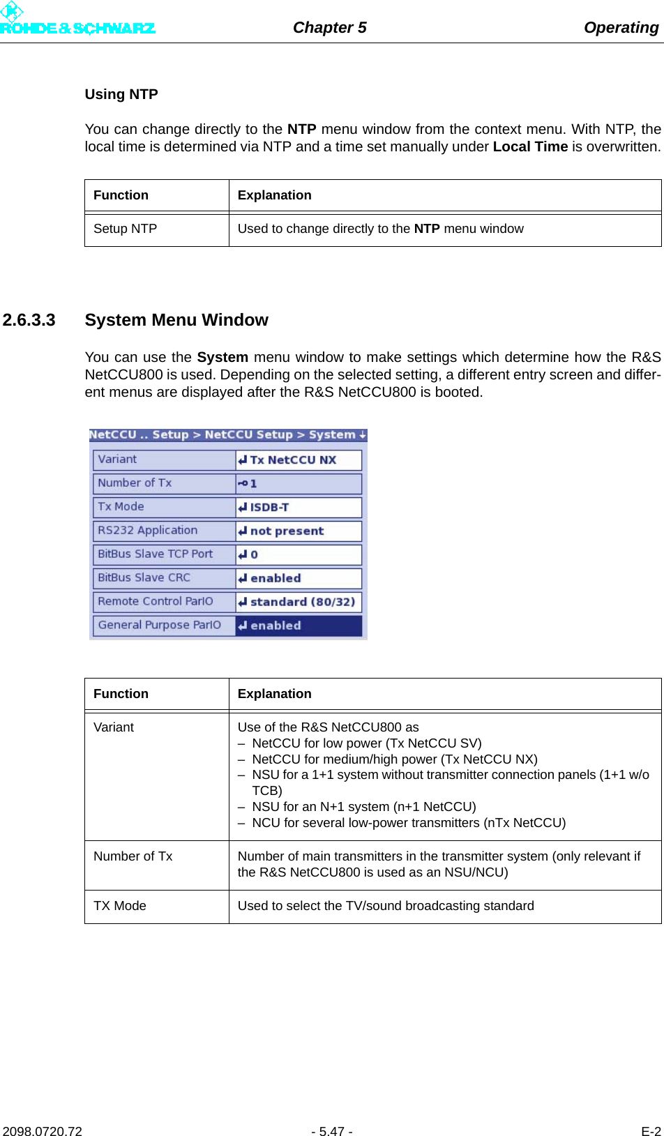
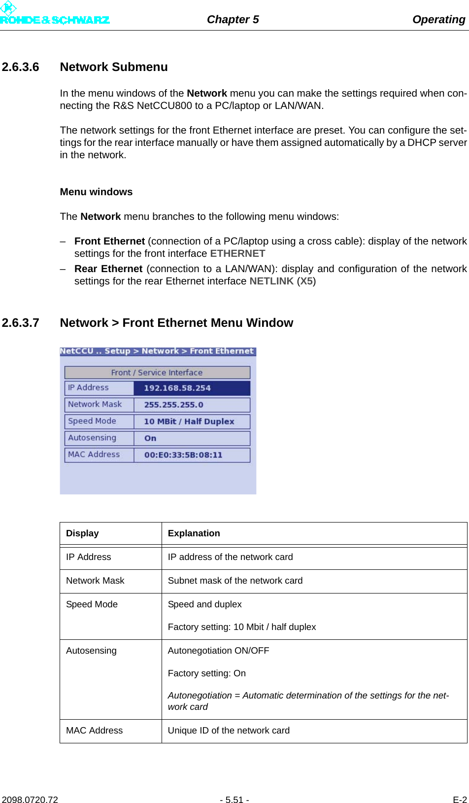
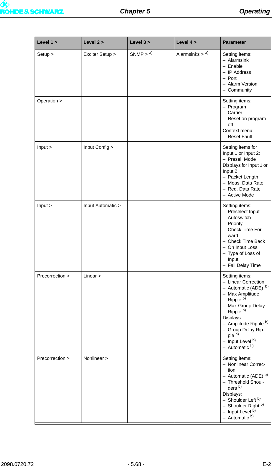
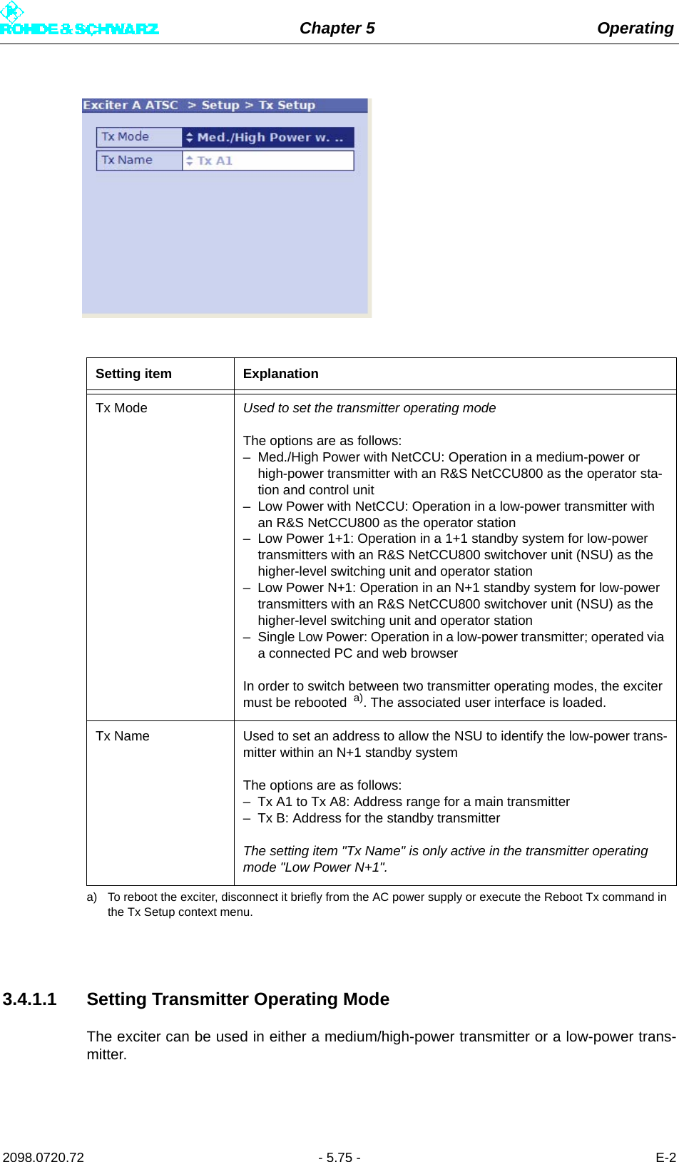
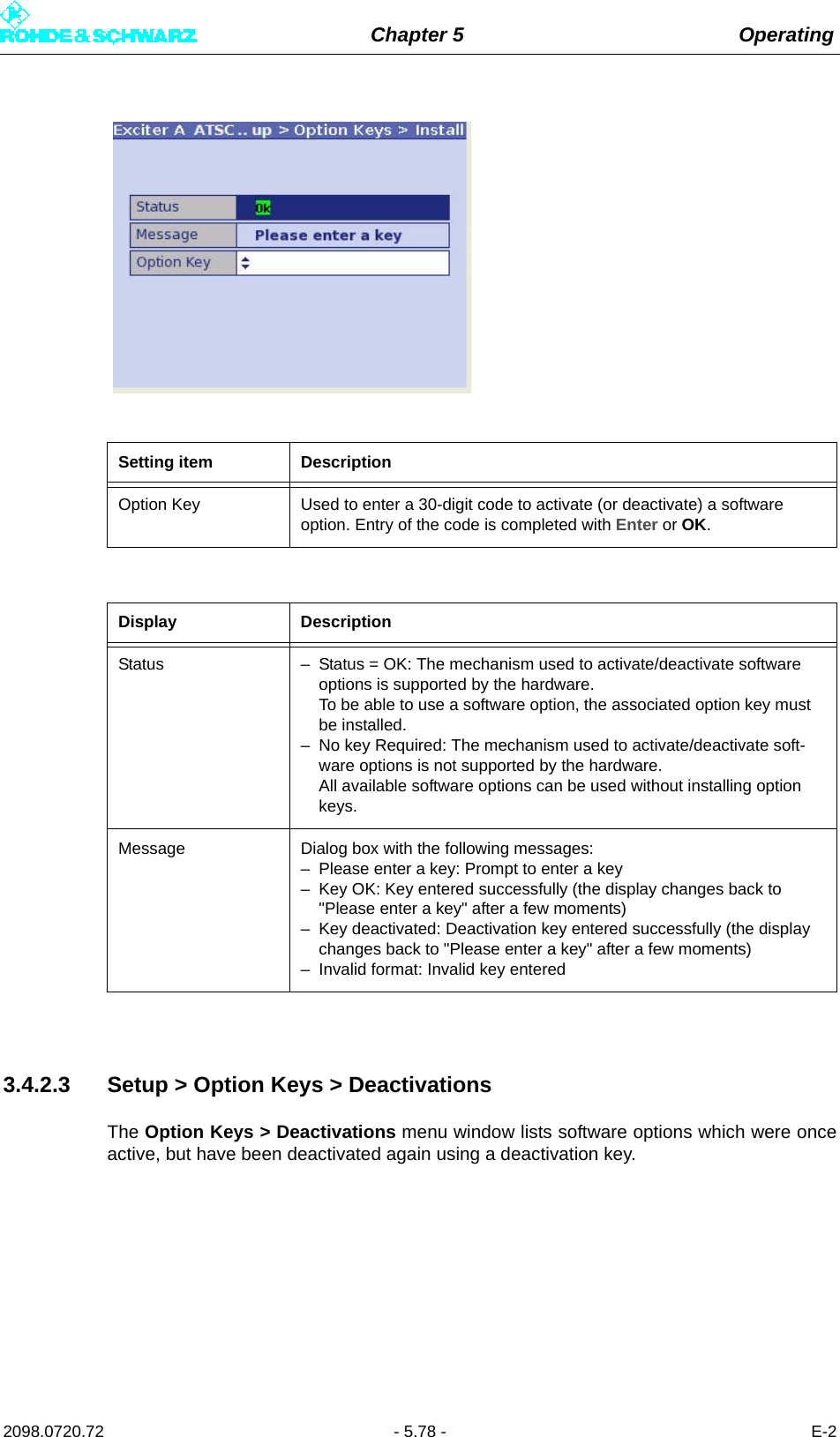
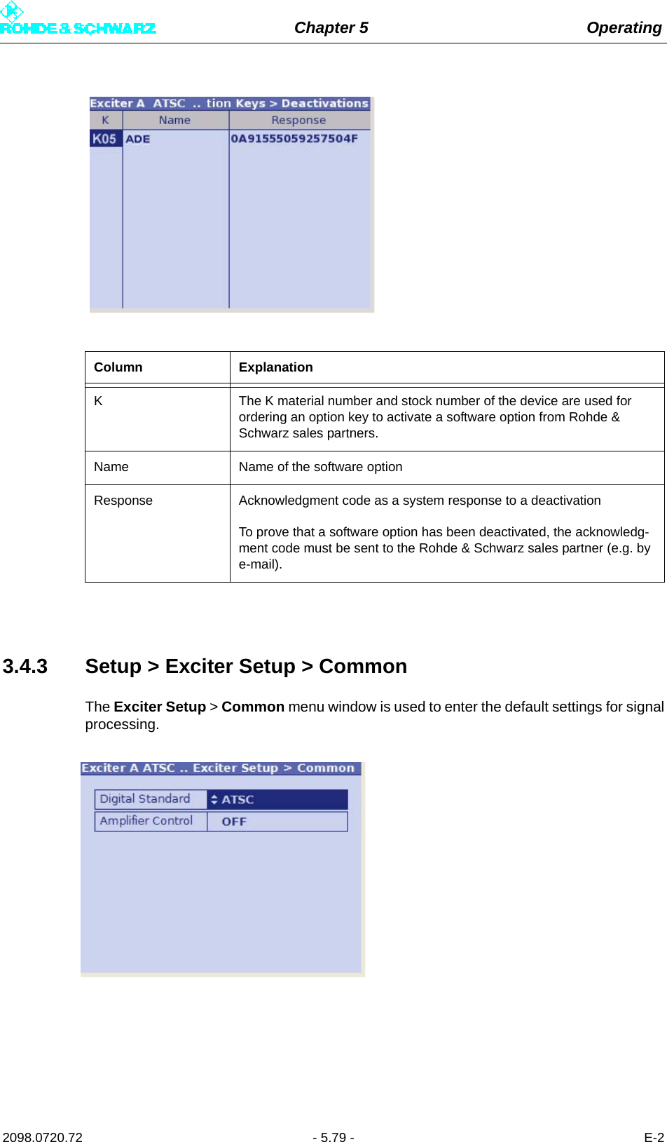
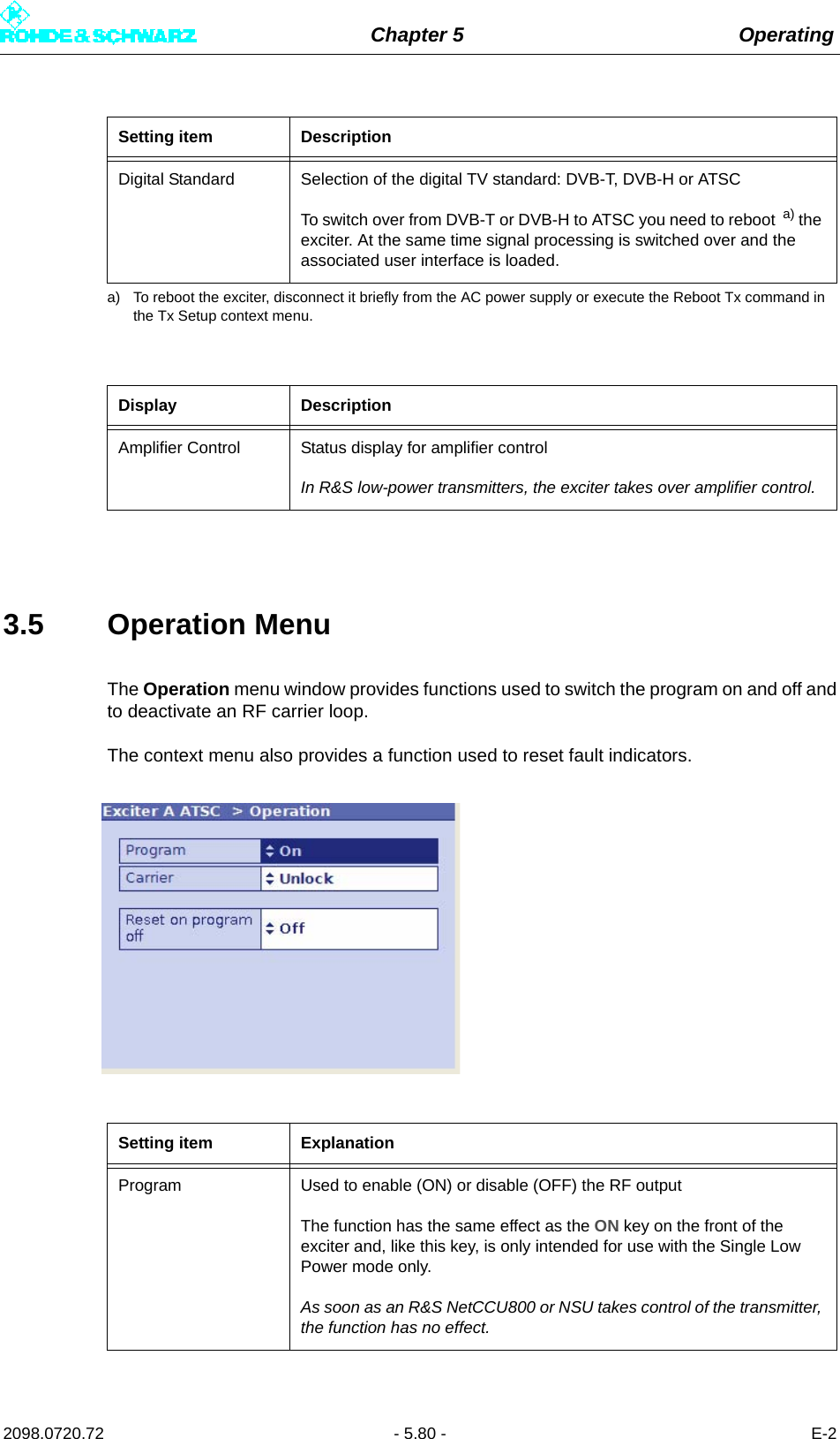
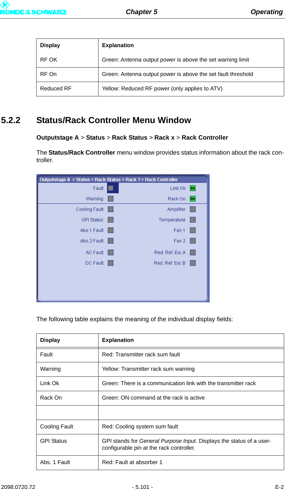
![Chapter 5 Operating2098.0720.72 - 5.67 - E-2Setup > Tx Setup > Setting items:–Tx Mode–Tx NameSetup > Option Keys > Status > Displays:–K–Name– Status: activated/not activated– ValiditySetup > Option Keys > Install > Setting items:– Option KeyDisplays:–Status– MessageSetup > Option Keys > Deactivation > Displays:–K–Name– ResponseSetup > Exciter Setup > Common > Setting items:– Digital StandardDisplays:– Amplifier ControlSetup > Exciter Setup > Date / Time > Setting items:–Date–TimeSetup > Exciter Setup > Ethernet > Setting items/dis-plays for the rear Eth-ernet interface:– IP Address– Subnet Mask– GatewayDisplays for the Front Ethernet port:– IP Address– Subnet Mask–MACSetup > Exciter Setup > BitBus > a) Setting items:– BitBus Protocol–TCP Port– ChecksumDisplays:– ConnectedContext menu:– ReconnectSetup > Exciter Setup > SNMP > a) General > a) Setting items:– Port SET/GET– Inhibit Status– Max. not transmit-tedSetup > Exciter Setup > SNMP > a) Manager > a) Setting items:– Access Level [1 to 5]– Community [1 to 5]– Enable [1 to 5]Level 1 > Level 2 > Level 3 > Level 4 > Parameter](https://usermanual.wiki/Rohde-and-Schwarz/NV830X.User-Manual-Part-2/User-Guide-1672827-Page-73.png)
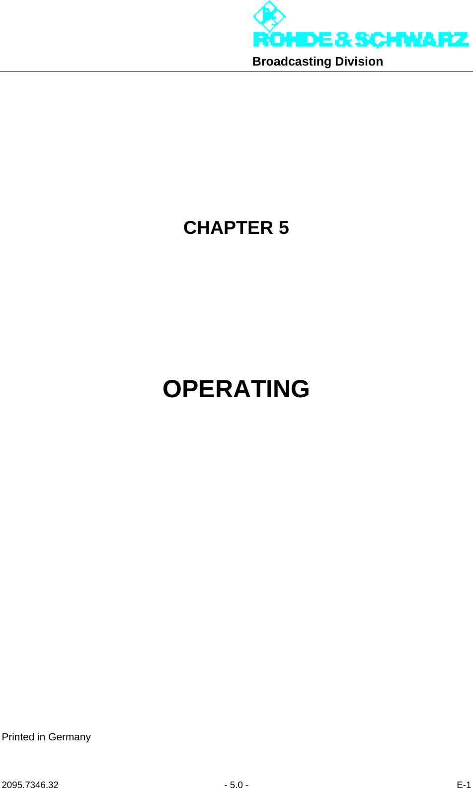
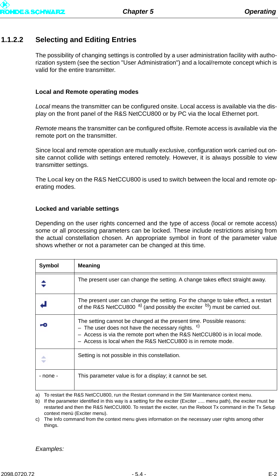
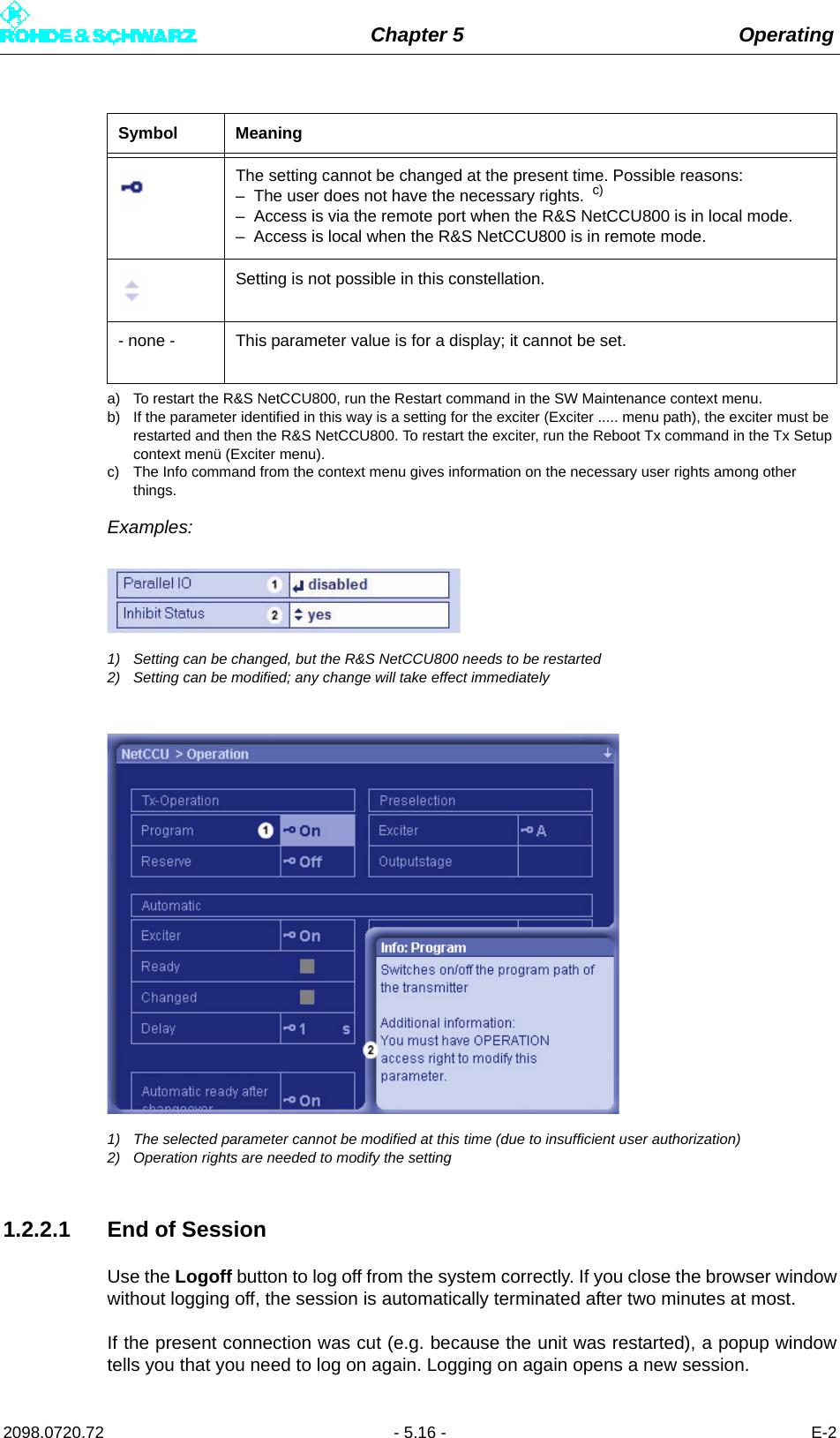
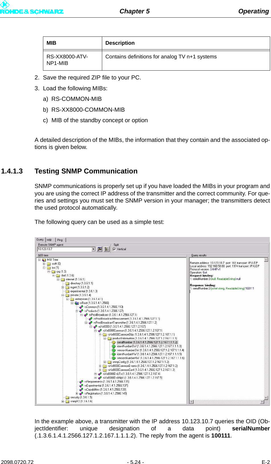
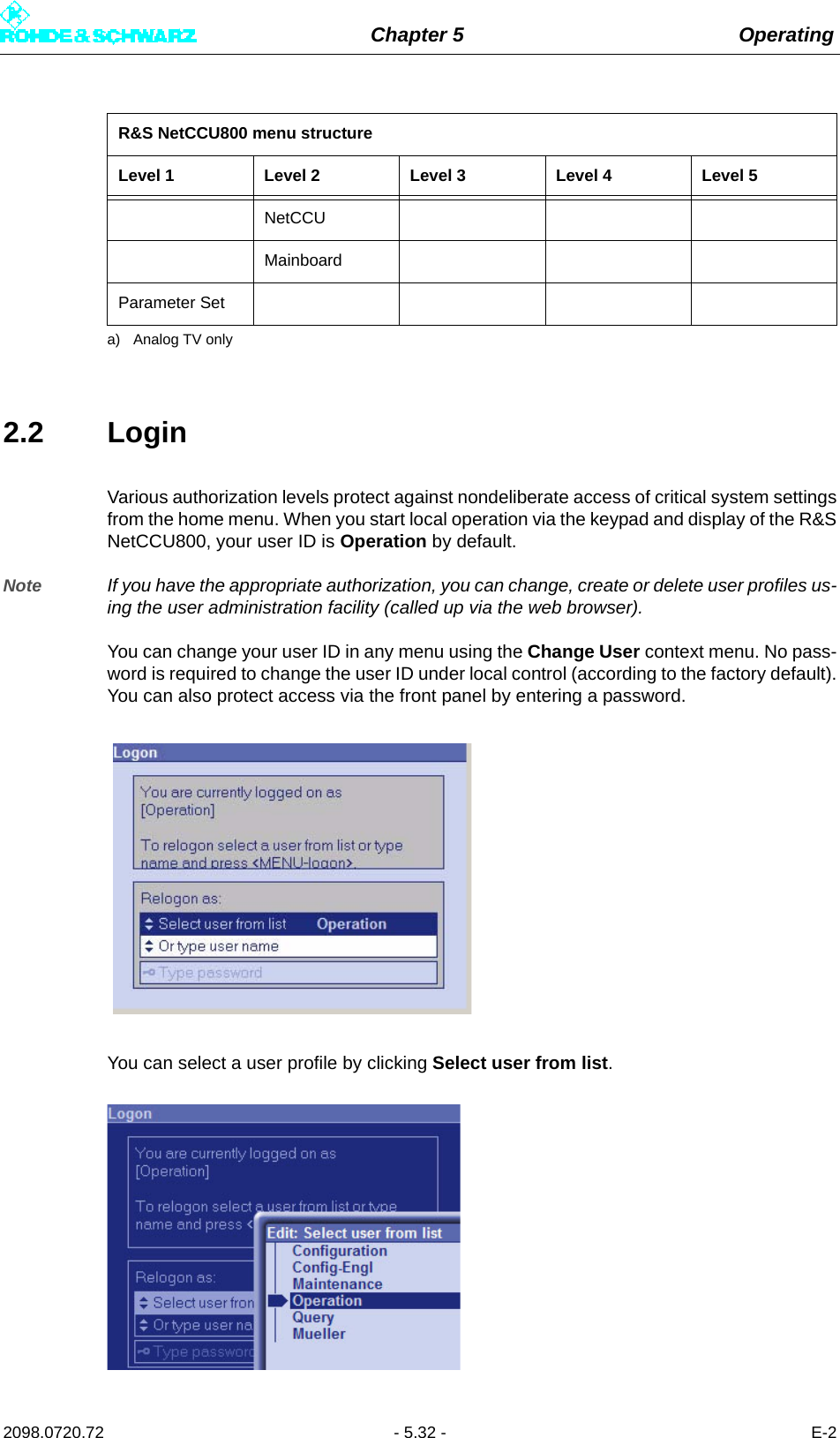
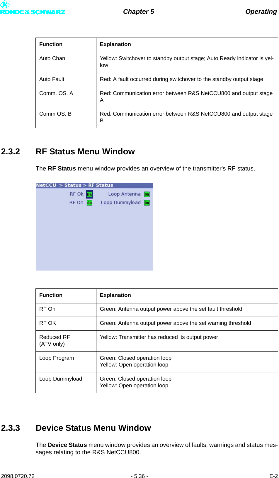
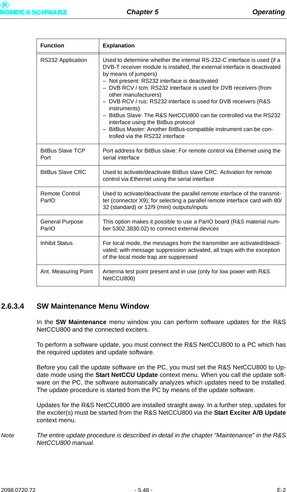
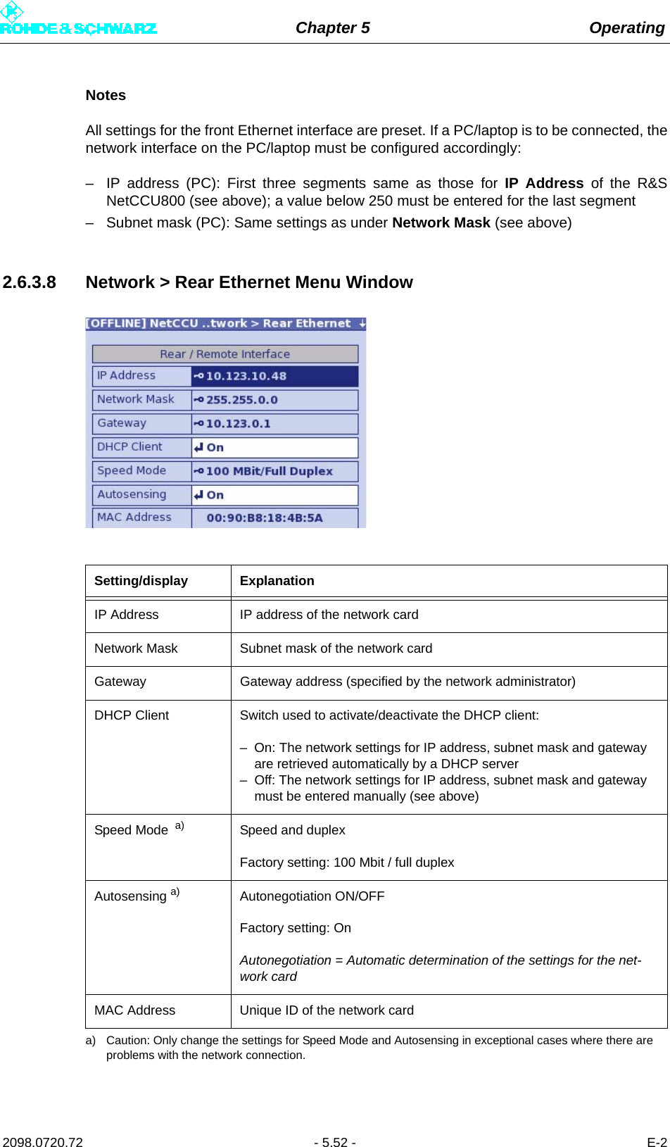
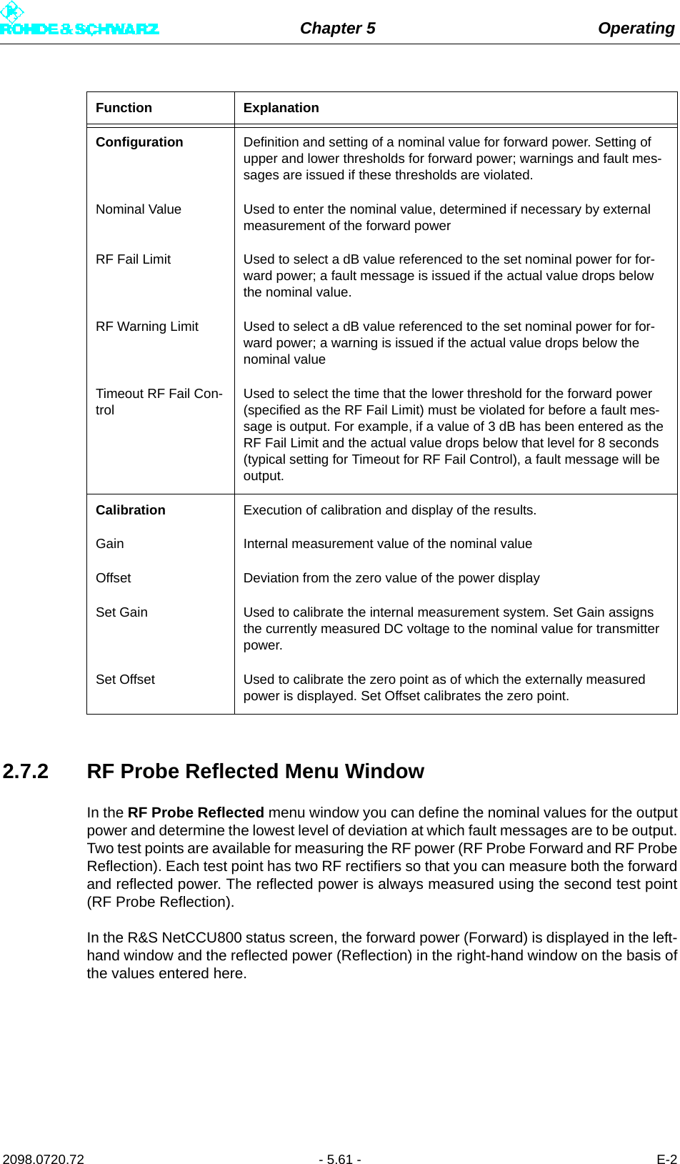
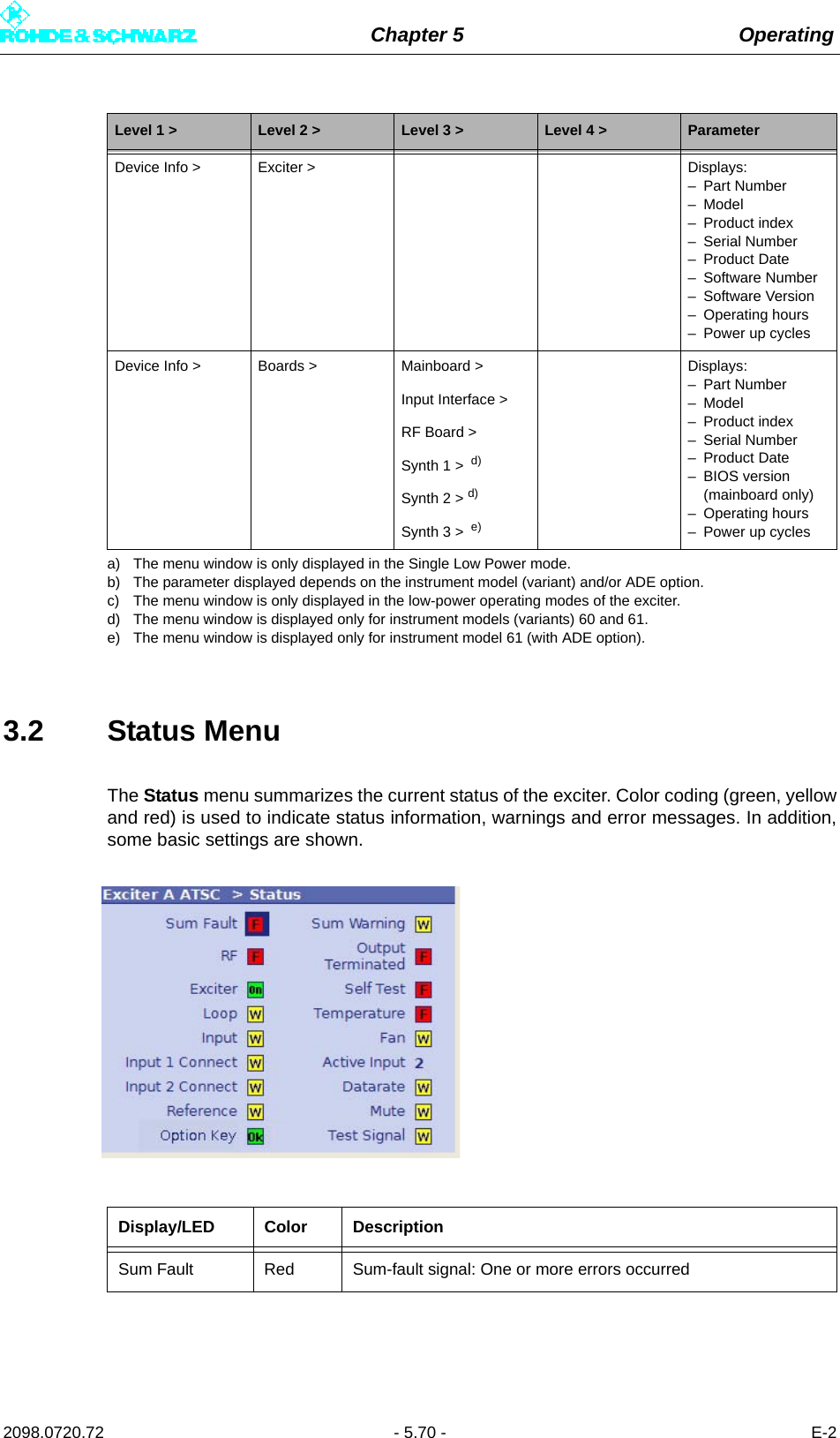
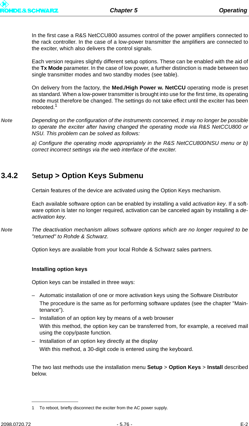
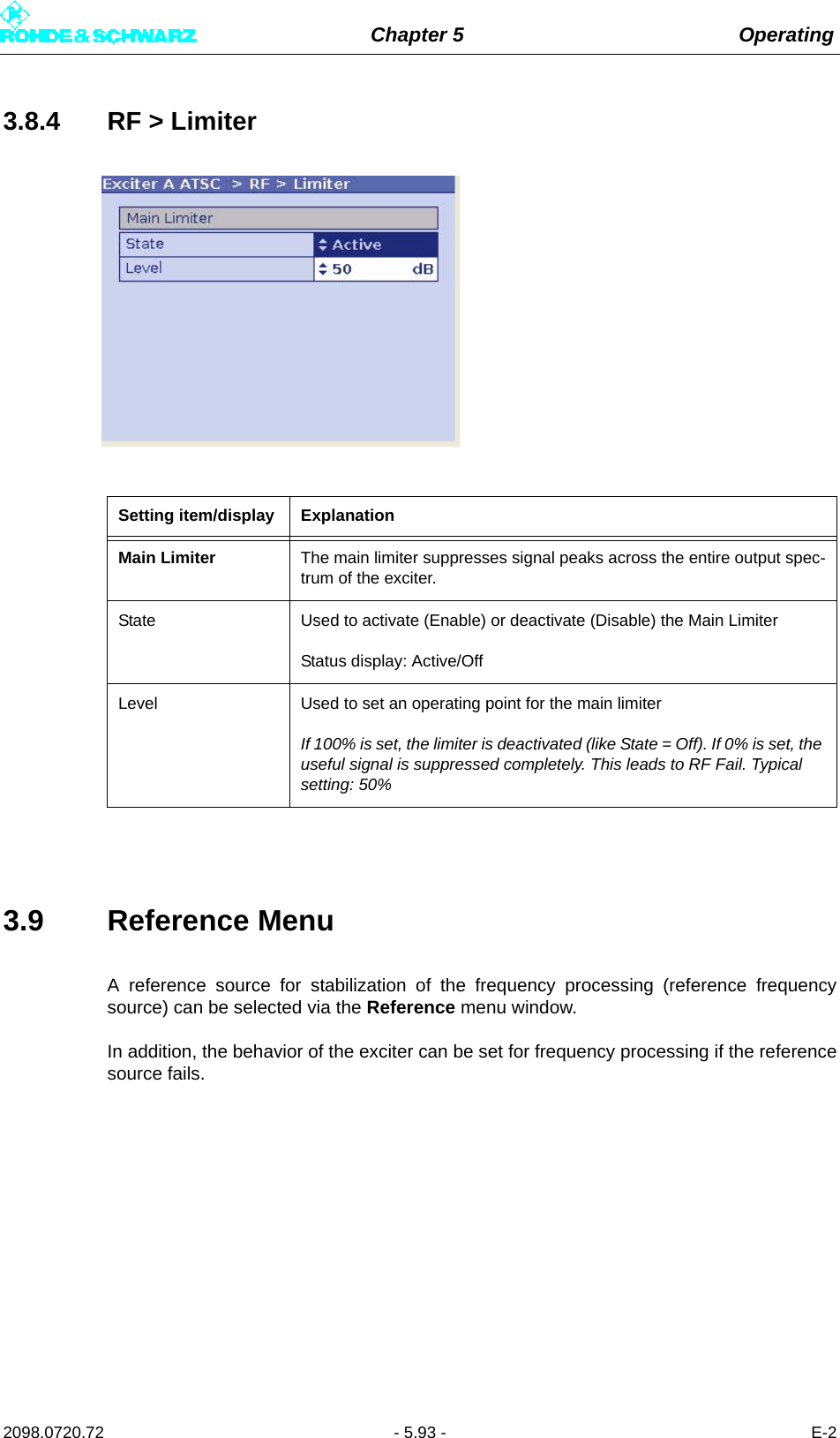
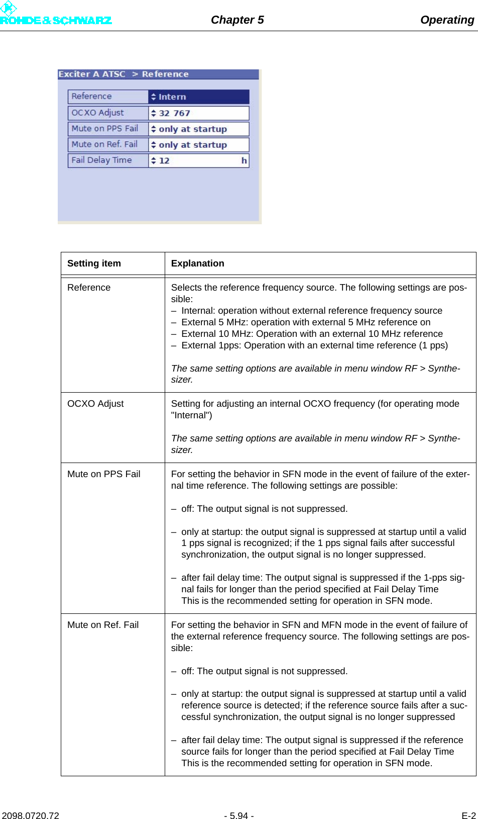
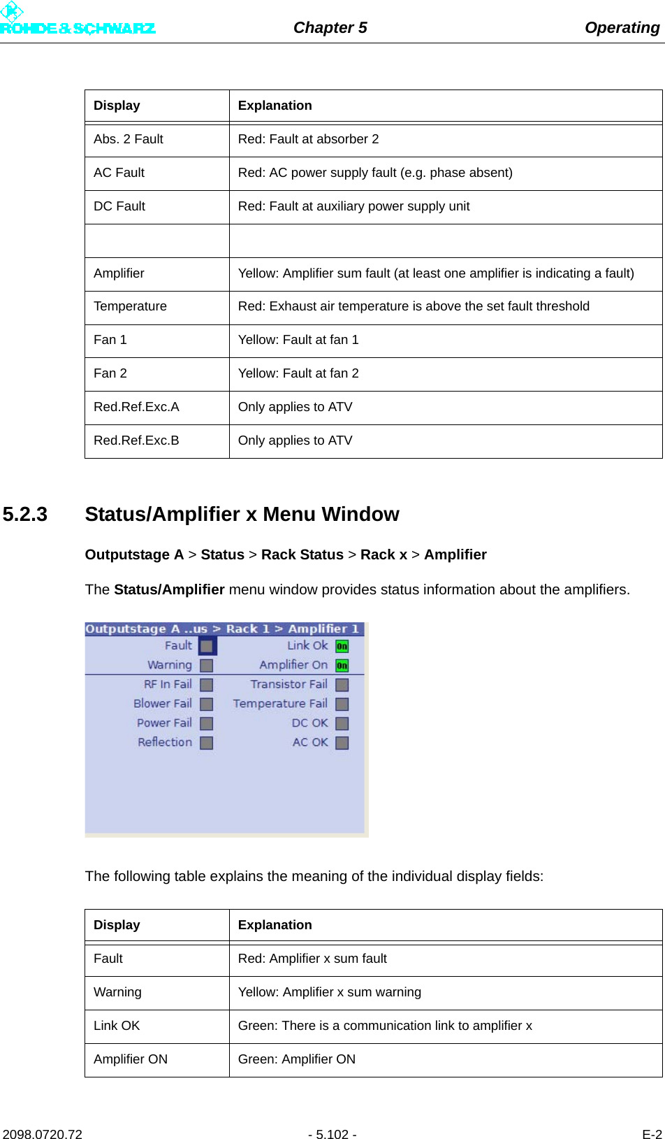
![Chapter 5 Operating2098.0720.72 - 5.69 - E-2RF > Synthesizer > Setting items:– Frequency– Reference–OCXO AdjustRF > Output > Setting items:– RF Output– Regulation– Manual RF Level– Output Attenuation–RF Slope– Modulation SlopeDisplays:– AGC RegulationRF > IQ Adjust > Setting items:– Auto I/Q Adjust (Start/Break)– I/Q Test Signal– Bias Coarse [I/Q]– Bias Fine [I/Q]– Gain [I/Q]– PhaseDisplays– Auto I/Q Adjust (Adjusted/Not Adjusted/In Progress)– LO1 FrequencyRF > Limiter > Setting points for main limiter:–State– LevelAmplifier > c) Setup > c) Setting items:– Ref Voltage– Nominal Power– RF Fail LimitDisplays:– RF Fail–Amplifier– Actual PowerAmplifier > c) Calibration > c) Setting items:– Ref Voltage– Nominal Power– CalibrationDisplays:– Actual Power– Calibration Power– Calibration OffsetReference > Setting items– Reference–OCXO Adjust– Mute on PPS Fail– Mute on Ref. Fail– Fail Delay TimeLevel 1 > Level 2 > Level 3 > Level 4 > Parameter](https://usermanual.wiki/Rohde-and-Schwarz/NV830X.User-Manual-Part-2/User-Guide-1672827-Page-75.png)
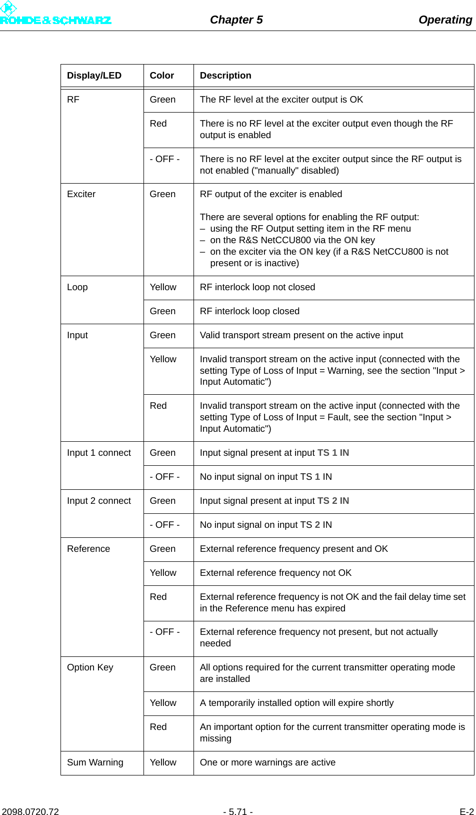
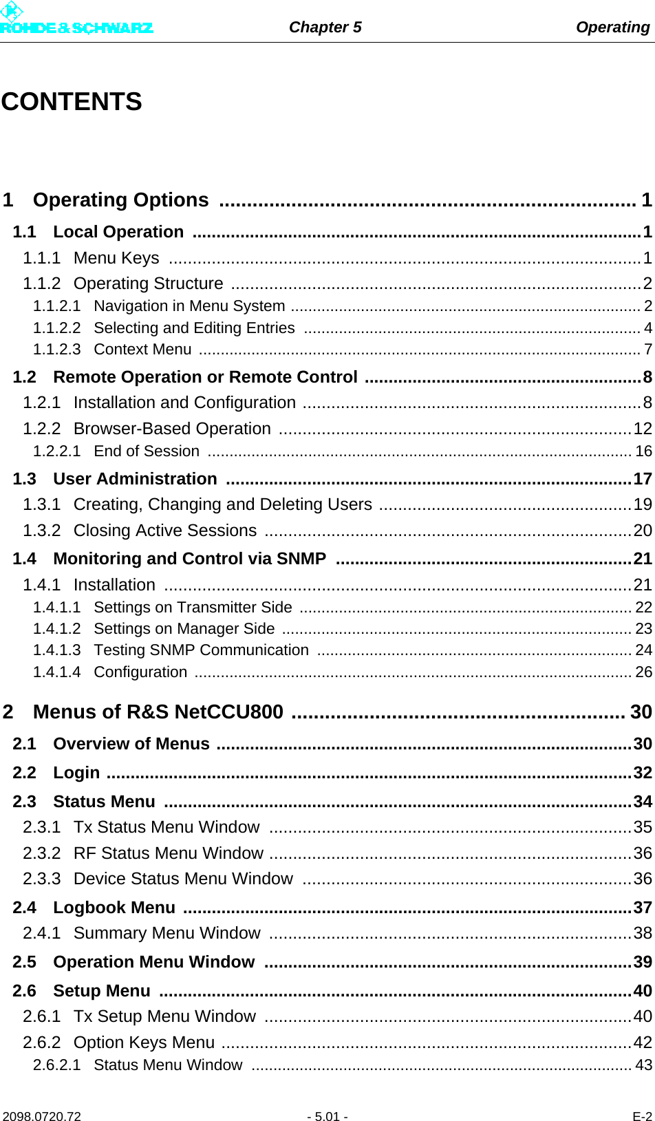
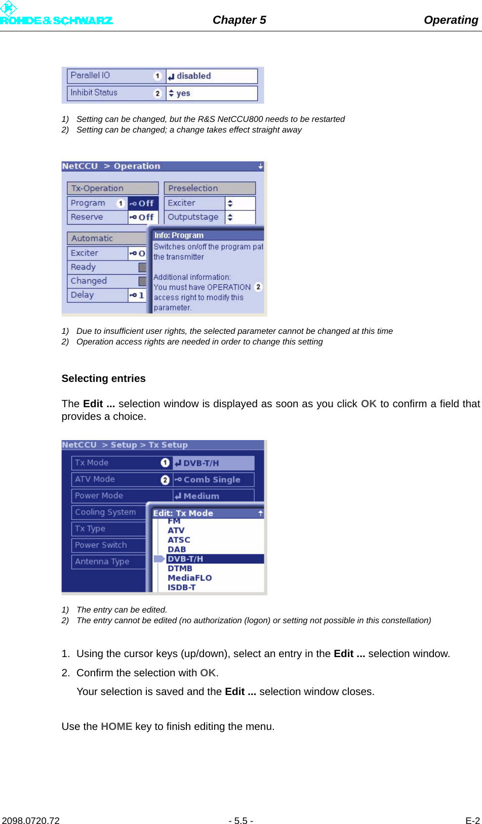
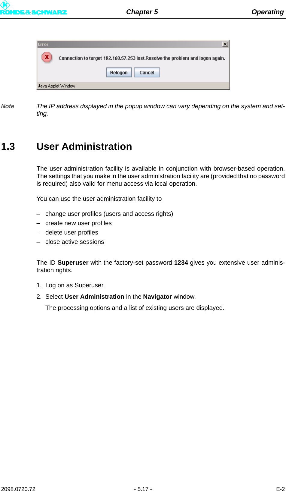
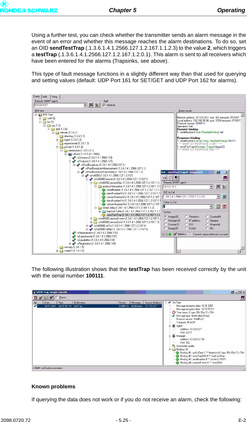
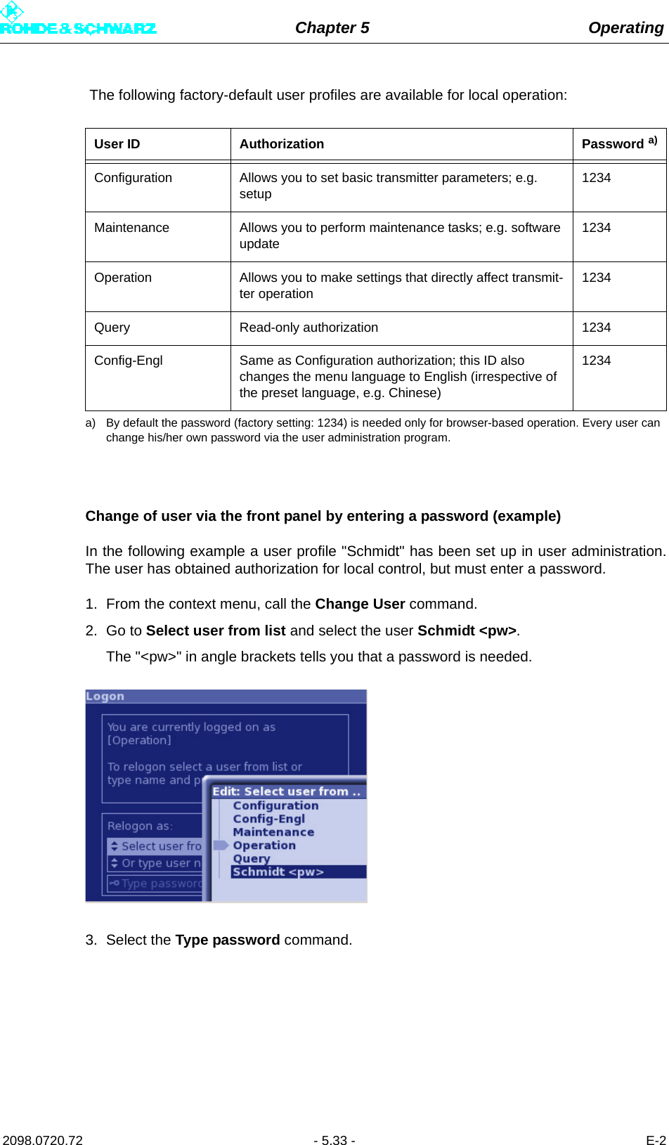
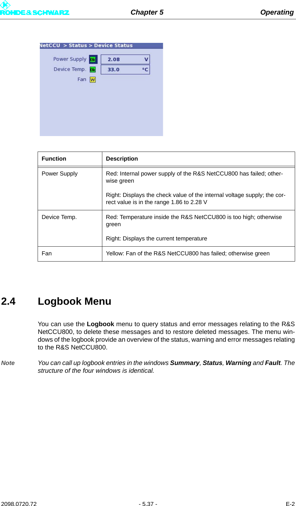
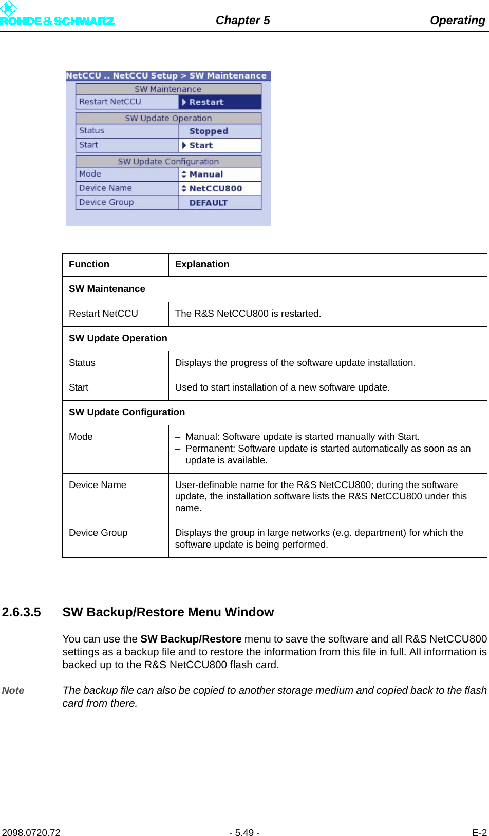
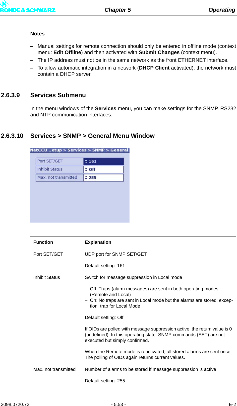
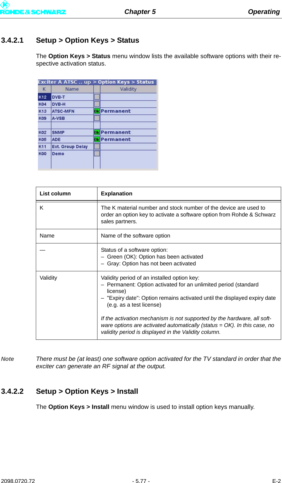
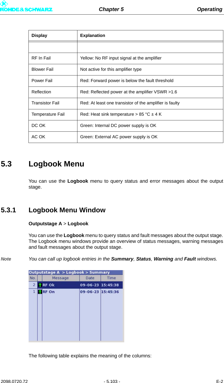
![Chapter 5 Operating2098.0720.72 - 5.72 - E-23.2.1 Status Displays, Warnings, and Error MessagesWhen warnings and error messages occur, this usually means that transmission operationis impaired. Different signal colors are used to distinguish the severity of an impairment orthe "quality" of the defect. The following applies:Note This type of LED signaling using colors and abbreviations (OK, W, F, etc) is identical for thecomplete menu.Indications with and without memory effectStatus displays (green) and warnings (yellow) always reflect the current status of the excit-er. On the other hand, error messages (red) remain active even after the reason for the errorhas passed or the error has been corrected. If the error has been corrected, you can resetthe error display with the RESET key.3.3 Logbook MenuThe logbook is used to record changes in state (events) of the exciter. Output TerminatedRed The cable-break sensor has reported that the RF output is not terminatedSelf Test Red A hardware fault has occurred in one or more modules of the exciter; detailed information about the fault is recorded in the log-bookTemperature Red At least one module is overheatingFan Yellow A fan has failed; there is a possibility of overheatingRed Both fans have failed; there is an acute risk of overheating Datarate Yellow Wrong data rate on the active inputMute Yellow Output signal from signal processing disabledTest signal Yellow Exciter is set to test modeStatus display green [OK] Transmission is not impaired.Warning yellow [W] Although the exciter is functional, external influ-ences may impair transmission or transmission operation.Error message red [F] A severe error has occurred so that transmission operation is generally not possible.Display/LED Color Description](https://usermanual.wiki/Rohde-and-Schwarz/NV830X.User-Manual-Part-2/User-Guide-1672827-Page-78.png)
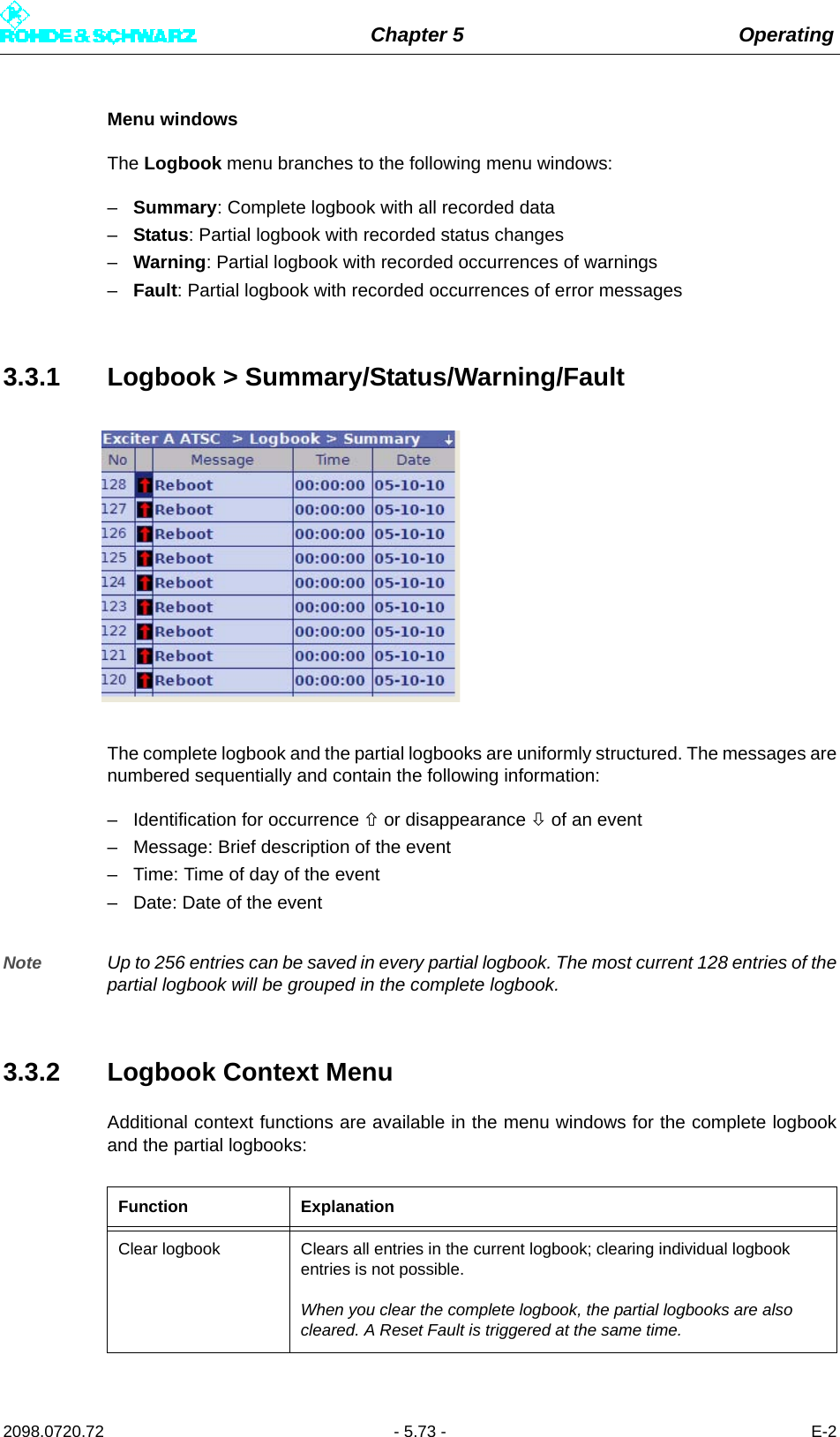
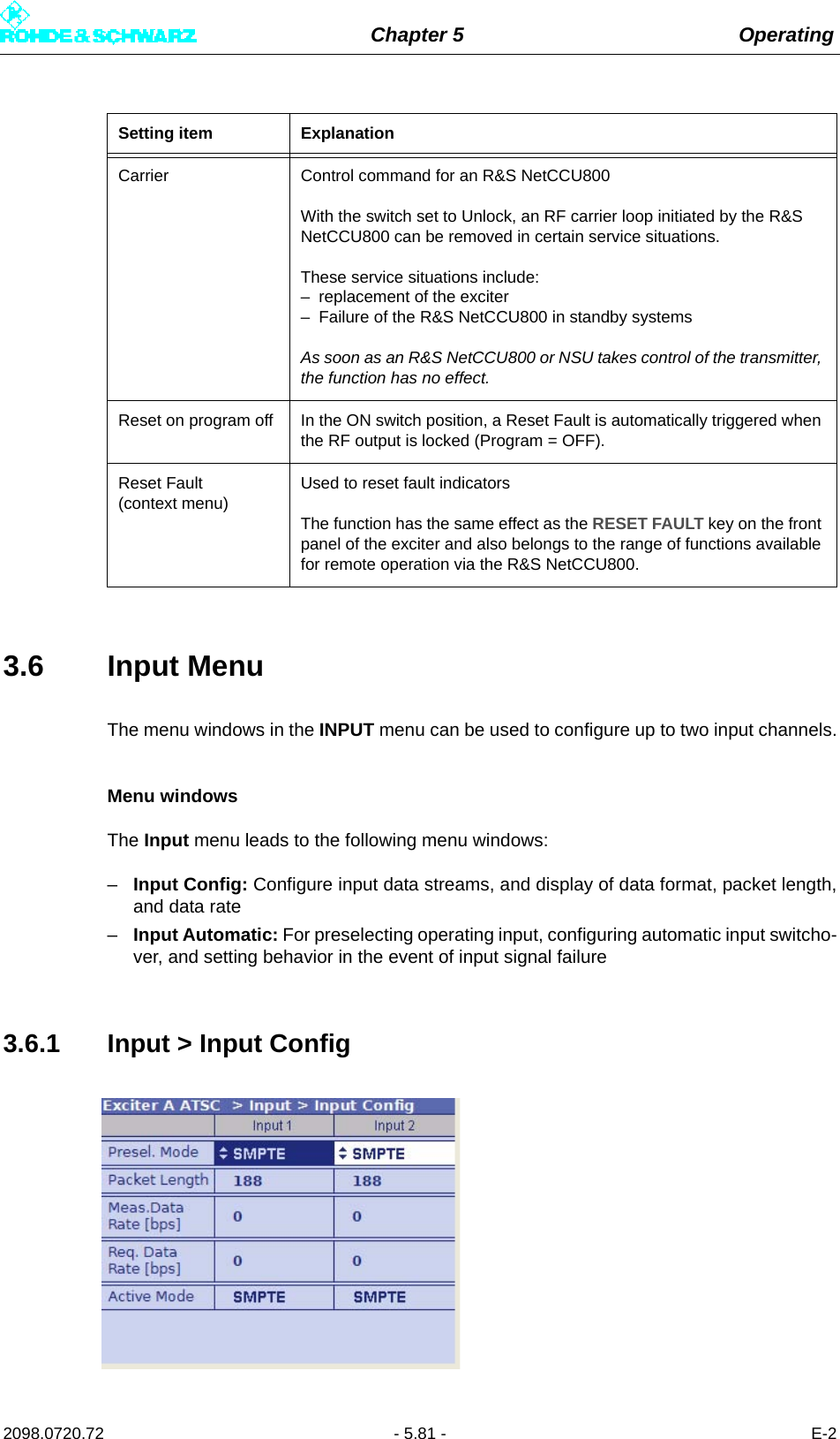
![Chapter 5 Operating2098.0720.72 - 5.82 - E-23.6.1.1 Checking Measured Data RateBy comparing the Meas. Data Rate [bps] and Req. Data Rate [bps], it is possible to checkthat the input buffers (FIFOs) are neither overflowing nor underflowing (both cases wouldresult in transmission interruptions).Maximum data processing rateFirst, all null packets are removed from the transport stream. The associated useful datarate is measured and displayed under Measured Data Rate. Trouble-free operation is pos-sible provided that this measurement value remains below the value for Required DataRate.Note After the useful data rate has been measured, stuffing to the required data rate is per-formed, i.e. the difference between Required Data Rate and Measured Data Rate is com-pensated by inserting null packets.Setting item ExplanationPresel. Mode[Input 1/Input 2]Sets the data format for the two data streams (main and standby sig-nals) on inputs TS 1 IN or TS 2 IN.The options are as follows:– AUTO: The data format is recognized automatically– ASI: Manual setting for an ASI transport stream– SMPTE: Manual setting for an SMPTE transport streamDisplay ExplanationPacket Length[Input 1/Input 2]Displays the packet length detected at the respective inputMeas.Data Rate [bps][Input 1/Input 2]Displays the data rate measured at the respective input without null packetsReq. Data Rate [bps][Input 1/Input 2]Display for checking the measured data rate. The maximum data pro-cessing rate is displayed.Active Mode Displays the data format detected or set at the respective input:– ASI: As described– SMTPE: As described– AUTO: Auto is selected and there is no data stream](https://usermanual.wiki/Rohde-and-Schwarz/NV830X.User-Manual-Part-2/User-Guide-1672827-Page-88.png)
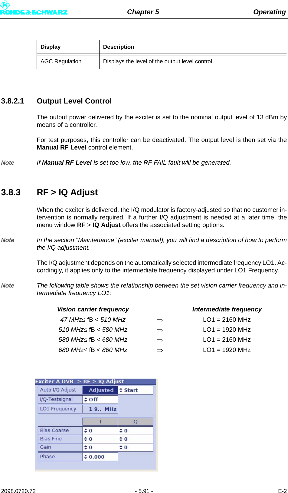
![Chapter 5 Operating2098.0720.72 - 5.92 - E-2Setting item/Dis-plays ExplanationAuto I/Q-Adjust Automatic I/Q adjustmentThe switch offers the following options:– Start: starts the automatic I/Q adjustment. The calculation takes approx. 1 minute. During this time (display Calc), the RF output signal is suppressed.– Break: immediately stops the adjustment. The modulator must then be adjusted again in any case.Important: Before performing the I/Q adjustment, make sure that the exciter has been in operation for at least 30 minutes. During adjustment, transmitter parameters must not be changed.The values for the actuators Bias Coarse, Bias Fine, Gain and Phase determined during automatic I/Q adjustment are displayed under the setting items of the same name for manual adjustment.The values are valid only for the intermediate frequency displayed under LO1 Frequency and can, if required, be checked and optimized with a manual I/Q adjustment (see section "Adjustment of I/Q modulator").I/Q Test Signal Switches a test signal on or off to manually perform the I/Q adjustment.Bias Coarse [I/Q] For coarse setting and display of an actuator for suppressing the undes-ired center carrier; setting range: -1023 to +1023Bias Fine [I/Q] For fine setting and display of an actuator for suppressing the undesired center carrier; setting range: -32767 to + 32767Gain [I/Q] For setting and display of an actuator for suppressing the undesired car-rier in the sideband; setting range: 0 to 255Phase For setting and display of an actuator for suppressing the undesired car-rier in the sideband; setting range: -14 to +14Display ExplanationAuto I/Q Adjust Status display of automatic I/Q adjustment:– In Progress: an adjustment has been started; the calculation is cur-rently being performed.– Adjusted: After completion of the adjustment, the display changes from "In Progress" to "Adjusted". This status is valid until a new and automatic I/Q adjustment is carried out. The "Adjusted" display does not necessarily mean that the modulator is (currently still) adjusted.– Not Adjusted: An error has occurred during the last adjustment. The automatic I/Q adjustment has to be repeated. If the automatic I/Q adjustment is still not functioning after several attempts, contact tech-nical support.LO1 Frequency Display of the intermediate frequency LO1 which is automatically set in the modulator (1.92 GHz or 2.16 GHz)The adjustment values of the above actuators are only valid for the dis-played intermediate frequency.](https://usermanual.wiki/Rohde-and-Schwarz/NV830X.User-Manual-Part-2/User-Guide-1672827-Page-98.png)
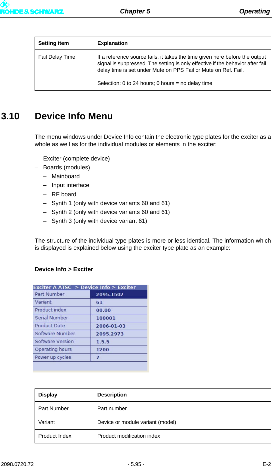
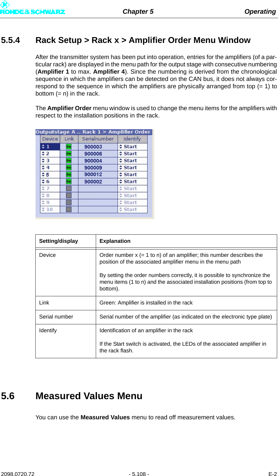
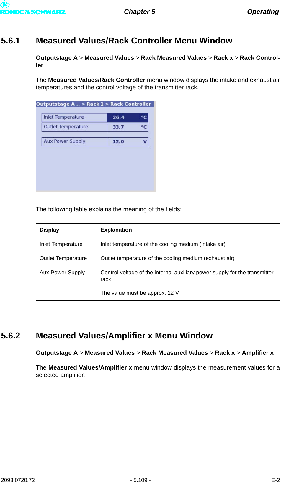
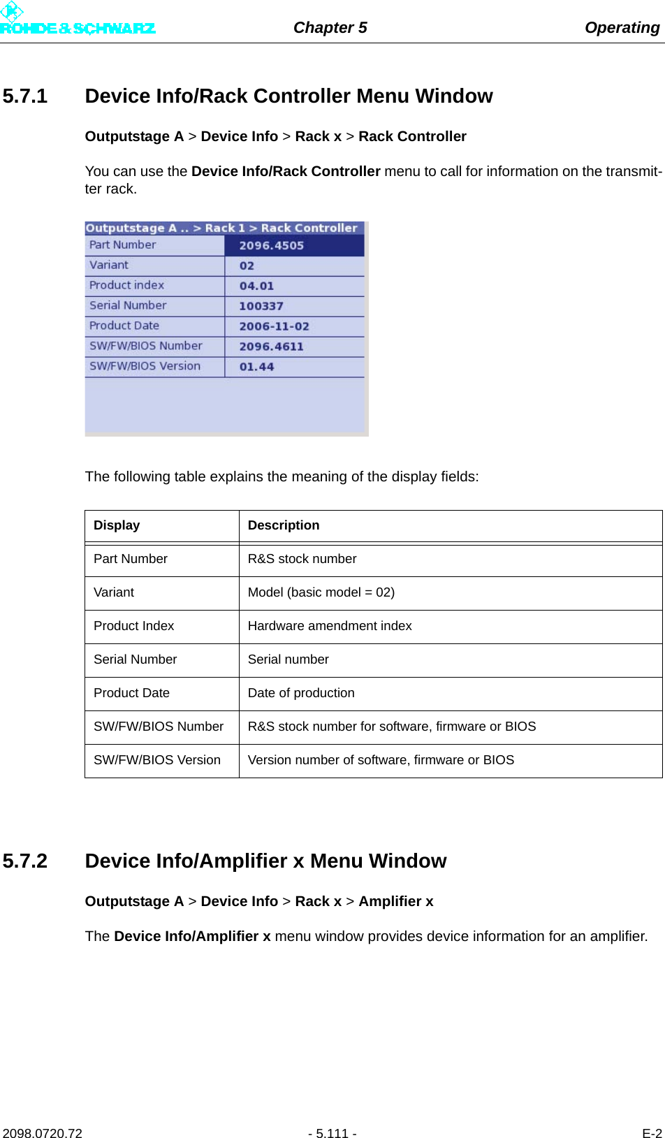
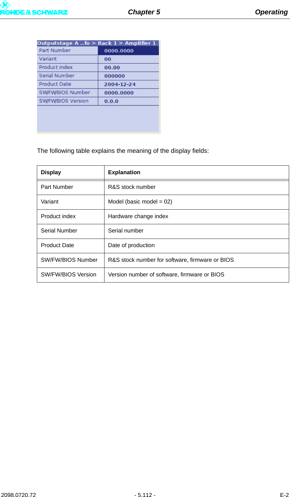
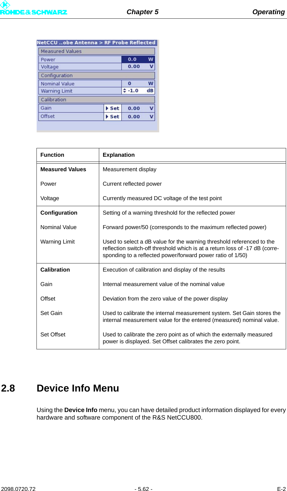
![Chapter 5 Operating2098.0720.72 - 5.110 - E-2The following table explains the meaning of the fields:5.7 Device Info MenuYou can use the Device Info menu to call for information on the transmitter rack. Display ExplanationI[xA] Module current of an output stage module, x = 1 to 4 a)a) With the amplifier type R&S VH8300A1, the measured current values I[4A] and I[1B] to I[4B] are not dis-played.I[xB] Module current of an output stage module, x = 1 to 4 a) b) c)b) With the amplifier type R&S VH8200A1, the measured current values I[1B] and I[4B] are not displayed.c) With the amplifier type R&S VM8530A1, the measured current values I[3B] and I[4B] are not displayed. The displayed measurement values correspond to the individual transistor currents.I[Drv] Current of the driver stageU[DC] Supply voltage of the amplifierI[DC] Total DC currentU[DC_CTRL] Reference voltage of the amplifierU[REG] AGC voltage of the amplifierPWR[A] Detector voltage of the power detector DET_APWR[B] Detector voltage of the power detector DED_BPWR[Out] Forward voltage of the output-power detectorPWR[Refl] Reflected voltage of the reflected-power detectorPWR[Ref] Reference voltage of the output-power detector](https://usermanual.wiki/Rohde-and-Schwarz/NV830X.User-Manual-Part-2/User-Guide-1672827-Page-116.png)