Rohde and Schwarz NV830X UHF 1.8kW maximum Digital TV transmitter User Manual 32 SLX8000 12 12 07 01 00
Rohde & Schwarz Inc UHF 1.8kW maximum Digital TV transmitter 32 SLX8000 12 12 07 01 00
Contents
- 1. User Manual Part 1
- 2. User Manual Part 2
- 3. User Manual Part 3
User Manual Part 2

Broadcasting Division
2095.7346.32 - 5.0 - E-1
CHAPTER 5
OPERATING
Printed in Germany

Chapter 5 Operating
2098.0720.72 - 5.01 - E-2
CONTENTS
1 Operating Options ........................................................................... 1
1.1 Local Operation ..............................................................................................1
1.1.1 Menu Keys ...................................................................................................1
1.1.2 Operating Structure ......................................................................................2
1.1.2.1 Navigation in Menu System ................................................................................ 2
1.1.2.2 Selecting and Editing Entries ............................................................................. 4
1.1.2.3 Context Menu ..................................................................................................... 7
1.2 Remote Operation or Remote Control ..........................................................8
1.2.1 Installation and Configuration .......................................................................8
1.2.2 Browser-Based Operation ..........................................................................12
1.2.2.1 End of Session ................................................................................................. 16
1.3 User Administration .....................................................................................17
1.3.1 Creating, Changing and Deleting Users .....................................................19
1.3.2 Closing Active Sessions .............................................................................20
1.4 Monitoring and Control via SNMP ..............................................................21
1.4.1 Installation ..................................................................................................21
1.4.1.1 Settings on Transmitter Side ............................................................................ 22
1.4.1.2 Settings on Manager Side ................................................................................ 23
1.4.1.3 Testing SNMP Communication ........................................................................ 24
1.4.1.4 Configuration .................................................................................................... 26
2 Menus of R&S NetCCU800 ............................................................ 30
2.1 Overview of Menus .......................................................................................30
2.2 Login ..............................................................................................................32
2.3 Status Menu ..................................................................................................34
2.3.1 Tx Status Menu Window ............................................................................35
2.3.2 RF Status Menu Window ............................................................................36
2.3.3 Device Status Menu Window .....................................................................36
2.4 Logbook Menu ..............................................................................................37
2.4.1 Summary Menu Window ............................................................................38
2.5 Operation Menu Window .............................................................................39
2.6 Setup Menu ...................................................................................................40
2.6.1 Tx Setup Menu Window .............................................................................40
2.6.2 Option Keys Menu ......................................................................................42
2.6.2.1 Status Menu Window ....................................................................................... 43

Chapter 5 Operating
2098.0720.72 - 5.02 - E-2
2.6.2.2 Install Menu Window ........................................................................................ 44
2.6.2.3 Deactivations Menu Window ............................................................................ 44
2.6.3 NetCCU Setup Menu ..................................................................................45
2.6.3.1 Common Menu Window ................................................................................... 45
2.6.3.2 Date/Time Menu Window ................................................................................. 46
2.6.3.3 System Menu Window ...................................................................................... 47
2.6.3.4 SW Maintenance Menu Window ...................................................................... 48
2.6.3.5 SW Backup/Restore Menu Window ................................................................. 49
2.6.3.6 Network Submenu ............................................................................................ 51
2.6.3.7 Network > Front Ethernet Menu Window ......................................................... 51
2.6.3.8 Network > Rear Ethernet Menu Window .......................................................... 52
2.6.3.9 Services Submenu ........................................................................................... 53
2.6.3.10 Services > SNMP > General Menu Window .................................................... 53
2.6.3.11 Services > SNMP > Manager Menu Window ................................................... 54
2.6.3.12 Services > SNMP > Alarmsinks Menu Window ................................................ 54
2.6.3.13 Services > NTP Menu Window ......................................................................... 55
2.6.3.14 Services > RS232 Menu Window ..................................................................... 56
2.6.4 ParIO Cards Order Menu Window .............................................................57
2.6.5 General Purpose ParIO Menu Window ......................................................59
2.7 RF Probe Antenna Menu ..............................................................................60
2.7.1 RF Probe Forward Menu Window ..............................................................60
2.7.2 RF Probe Reflected Menu Window ............................................................61
2.8 Device Info Menu ..........................................................................................62
2.8.1 NetCCU Menu Window ..............................................................................63
2.8.2 Mainboard Menu Window ...........................................................................63
2.9 Parameter Set Menu Window ......................................................................63
3 Menus of Exciter A/B ..................................................................... 66
3.1 Overview of Menus .......................................................................................66
3.2 Status Menu ..................................................................................................70
3.2.1 Status Displays, Warnings, and Error Messages .......................................72
3.3 Logbook Menu ..............................................................................................72
3.3.1 Logbook > Summary/Status/Warning/Fault ...............................................73
3.3.2 Logbook Context Menu ..............................................................................73
3.4 Setup Menu ...................................................................................................74
3.4.1 Setup > Tx Setup .......................................................................................74
3.4.1.1 Setting Transmitter Operating Mode ................................................................ 75
3.4.2 Setup > Option Keys Submenu ..................................................................76
3.4.2.1 Setup > Option Keys > Status .......................................................................... 77
3.4.2.2 Setup > Option Keys > Install ........................................................................... 77
3.4.2.3 Setup > Option Keys > Deactivations ............................................................... 78

Chapter 5 Operating
2098.0720.72 - 5.03 - E-2
3.4.3 Setup > Exciter Setup > Common ..............................................................79
3.5 Operation Menu ............................................................................................80
3.6 Input Menu ....................................................................................................81
3.6.1 Input > Input Config ....................................................................................81
3.6.1.1 Checking Measured Data Rate ........................................................................ 82
3.6.2 Input > Input Automatic ..............................................................................83
3.6.2.1 Automatic Input Switchover .............................................................................. 84
3.6.2.2 Behavior with Defective Input Signal ................................................................ 85
3.7 Precorrection Menu ......................................................................................85
3.7.1 Precorrection > Linear ................................................................................85
3.7.2 Precorrection > Nonlinear ..........................................................................87
3.8 RF Menu ........................................................................................................88
3.8.1 RF > Synthesizer ........................................................................................88
3.8.1.1 Reference Frequency Source .......................................................................... 89
3.8.1.2 Holdover Mode (if reference frequency fails) ................................................... 90
3.8.2 RF > Output ................................................................................................90
3.8.2.1 Output Level Control ........................................................................................ 91
3.8.3 RF > IQ Adjust ............................................................................................91
3.8.4 RF > Limiter ................................................................................................93
3.9 Reference Menu ............................................................................................93
3.10 Device Info Menu ..........................................................................................95
4 Adjustment of I/Q Modulator ........................................................ 97
5 Menus of Outputstage A/B ............................................................ 98
5.1 Overview of Menus .......................................................................................98
5.2 Status Menu ..................................................................................................99
5.2.1 OS Status Menu Window .........................................................................100
5.2.2 Status/Rack Controller Menu Window ......................................................101
5.2.3 Status/Amplifier x Menu Window ..............................................................102
5.3 Logbook Menu ............................................................................................103
5.3.1 Logbook Menu Window ............................................................................103
5.4 Output Power Menu ....................................................................................104
5.4.1 Output Power Menu Window ....................................................................104
5.5 Setup Menu .................................................................................................105
5.5.1 OS Setup Menu Window ..........................................................................105
5.5.2 Rack Setup > Rack Order Menu Window ................................................106
5.5.3 Rack Setup > Rack x > Rack Controller Menu Window ...........................107
5.5.4 Rack Setup > Rack x > Amplifier Order Menu Window ............................108

Chapter 5 Operating
2098.0720.72 - 5.04 - E-2
5.6 Measured Values Menu ..............................................................................108
5.6.1 Measured Values/Rack Controller Menu Window ....................................109
5.6.2 Measured Values/Amplifier x Menu Window ............................................109
5.7 Device Info Menu ........................................................................................110
5.7.1 Device Info/Rack Controller Menu Window ..............................................111
5.7.2 Device Info/Amplifier x Menu Window ......................................................111
6 Other Menus ................................................................................. 113
6.1 TxTool Menu: Saving Transmitter Information ........................................113
6.1.1 Functions in LogBooks Window ...............................................................114
6.2 SW Backup/Restore Menu: Backing Up Complete System ....................115
6.3 Storage Menu: Saving Exciter Data ..........................................................116
6.3.1 Saving Parameter Data ............................................................................117
6.3.2 Recalling Parameter Data ........................................................................118
Chapter 5 Operating
2098.0720.72 - 5.1 - E-2
1 Operating Options
The transmitter is controlled using the R&S NetCCU800. The R&S NetCCU800 can be op-
erated in the following ways:
– Local operation via the display and menu keys on the front panel of the R&S
NetCCU800
– Operation via the web browser
– Monitoring and control via SNMP
If the unit is operated via the web browser of a connected PC/client computer, two modes
are possible:
– Remote operation via a directly connected PC (connector on front panel)
– Remote control via a remotely connected network client (connector on rear panel)
1.1 Local Operation
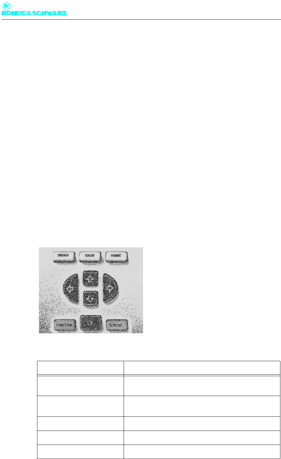
1.1.1 Menu Keys
Fig. 1 Menu operation
Key Meaning / function
MENU Starts the menu control function (activation from the system
overview); calls a context menu (activation from menu)
BACK Cancels an entered value if not confirmed with OK; used to
move one step back in the menu
HOME Used to return from the menu tree to the system overview.
FUNCTION Calls a context menu for the current menu entry
OK Confirms an entry or selection
Chapter 5 Operating
2098.0720.72 - 5.2 - E-2
1.1.2 Operating Structure
1.1.2.1 Navigation in Menu System
Note Different entry screens and menus are displayed depending on whether the R&S
NetCCU800 is used as a NetCCU (transmitter control) or as an NCU/NSU (control of low-
power transmitters / control of n+1 systems).
This is how you navigate within the menu system:
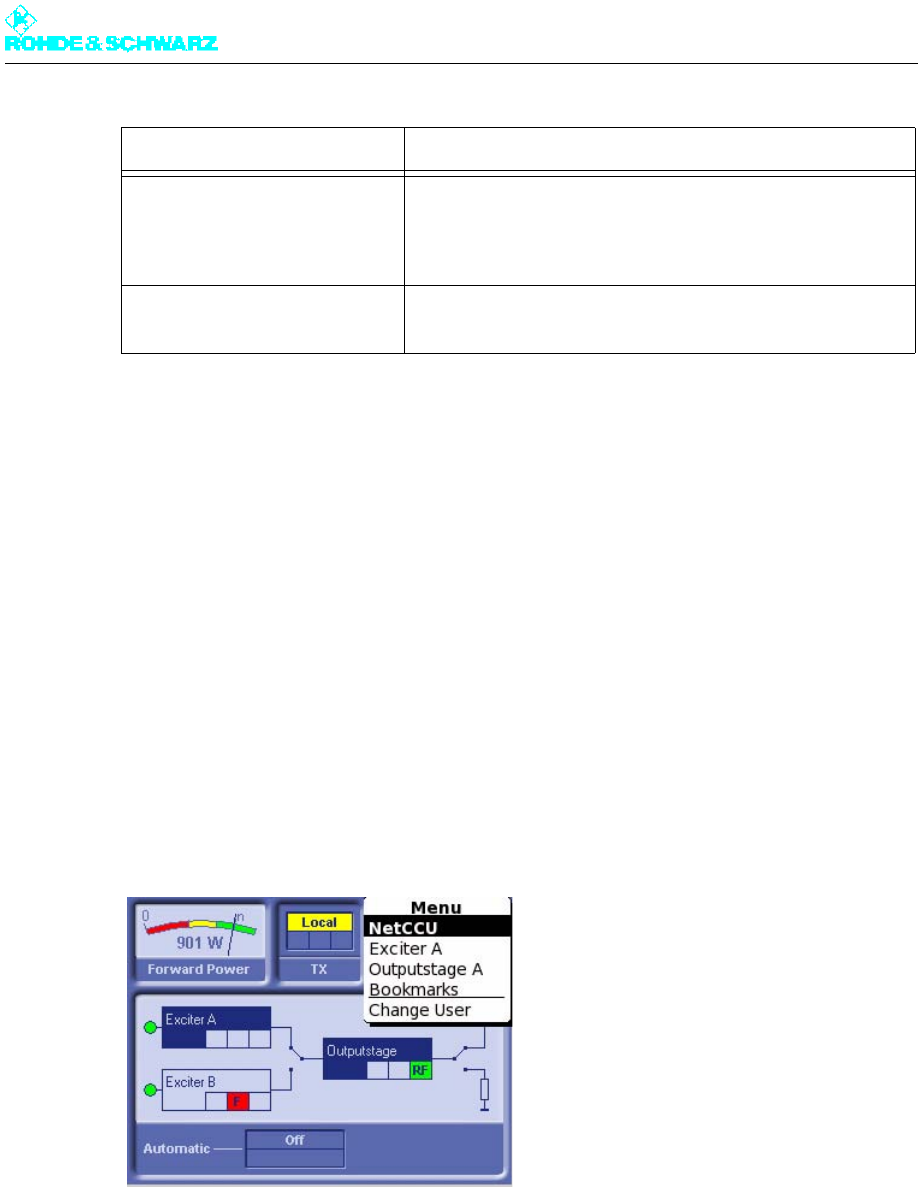
1. Press the MENU key.
The menu is called.
Note When you access the menu system for the first time, you are logged on by default under
the user ID Operation which authorizes you to make settings that directly affect trans-
mitter operation.
2. Select the required menu and confirm with OK.
The overview for the selected menu is then opened (here NetCCU).
STATUS Displays the system logbook (when activated from the sys-
tem overview); displays the status screen for a system com-
ponent (when activated after selecting a system component
from the menu)
CURSOR KEYS
Used to move through the menu structure and to highlight
menu elements; used to select entries
Key Meaning / function
Chapter 5 Operating
2098.0720.72 - 5.3 - E-2
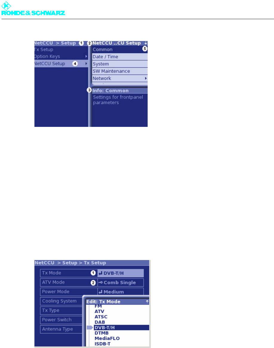
1) Window and title bar for higher-level menus
2) Window and title bar for lower-level menus (submenus of the main menu selected in the window at the left)
3) Window and title bar with explanation of currently selected menu
4) Menu contains additional submenus (no arrow symbol: a menu window will open)
5) Not all available menus are displayed (use cursor keys to scroll up/down)
3. Using the cursor keys in the left/right part of the window, select a menu and confirm with
OK.
If additional submenus are available, the higher-level menus are shown in the left-hand
window and the lower-level menus are shown in the right-hand window.
4. Using the cursor keys (up/down), select another menu or menu window from the right
side of the window and confirm with OK.
Using the cursor keys (up/down), select an entry in the menu window and confirm with
OK.
1) The entry can be edited.
2) The entry cannot be edited (no authorization (logon) or setting not possible in this constellation)
By using the MENU or FUNCTION key, you can call up a context menu from any position.
Use the BACK key to go back one step in the menu structure (even from the Help win-
dows); you can also use BACK to cancel an entered value as long as you have not already
confirmed it with OK.
Use the HOME key to exit the menu structure and return to the system overview.
Chapter 5 Operating
2098.0720.72 - 5.4 - E-2
1.1.2.2 Selecting and Editing Entries
The possibility of changing settings is controlled by a user administration facility with autho-
rization system (see the section "User Administration") and a local/remote concept which is
valid for the entire transmitter.
Local and Remote operating modes
Local means the transmitter can be configured onsite. Local access is available via the dis-
play on the front panel of the R&S NetCCU800 or by PC via the local Ethernet port.
Remote means the transmitter can be configured offsite. Remote access is available via the
remote port on the transmitter.
Since local and remote operation are mutually exclusive, configuration work carried out on-
site cannot collide with settings entered remotely. However, it is always possible to view
transmitter settings.
The Local key on the R&S NetCCU800 is used to switch between the local and remote op-
erating modes.
Locked and variable settings
Depending on the user rights concerned and the type of access (local or remote access)
some or all processing parameters can be locked. These include restrictions arising from
the actual constellation chosen. An appropriate symbol in front of the parameter value
shows whether or not a parameter can be changed at this time.
Examples:
Symbol Meaning
The present user can change the setting. A change takes effect straight away.
The present user can change the setting. For the change to take effect, a restart
of the R&S NetCCU800 a) (and possibly the exciter b)) must be carried out.
a) To restart the R&S NetCCU800, run the Restart command in the SW Maintenance context menu.
b) If the parameter identified in this way is a setting for the exciter (Exciter ..... menu path), the exciter must be
restarted and then the R&S NetCCU800. To restart the exciter, run the Reboot Tx command in the Tx Setup
context menü (Exciter menu).
The setting cannot be changed at the present time. Possible reasons:
– The user does not have the necessary rights. c)
– Access is via the remote port when the R&S NetCCU800 is in local mode.
– Access is local when the R&S NetCCU800 is in remote mode.
c) The Info command from the context menu gives information on the necessary user rights among other
things.
Setting is not possible in this constellation.
- none - This parameter value is for a display; it cannot be set.
Chapter 5 Operating
2098.0720.72 - 5.5 - E-2
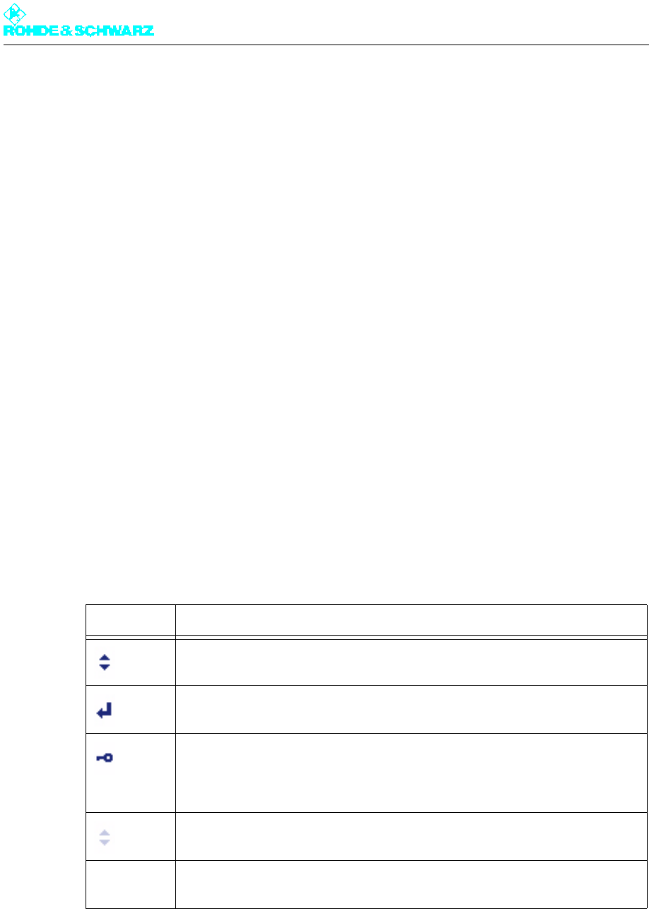
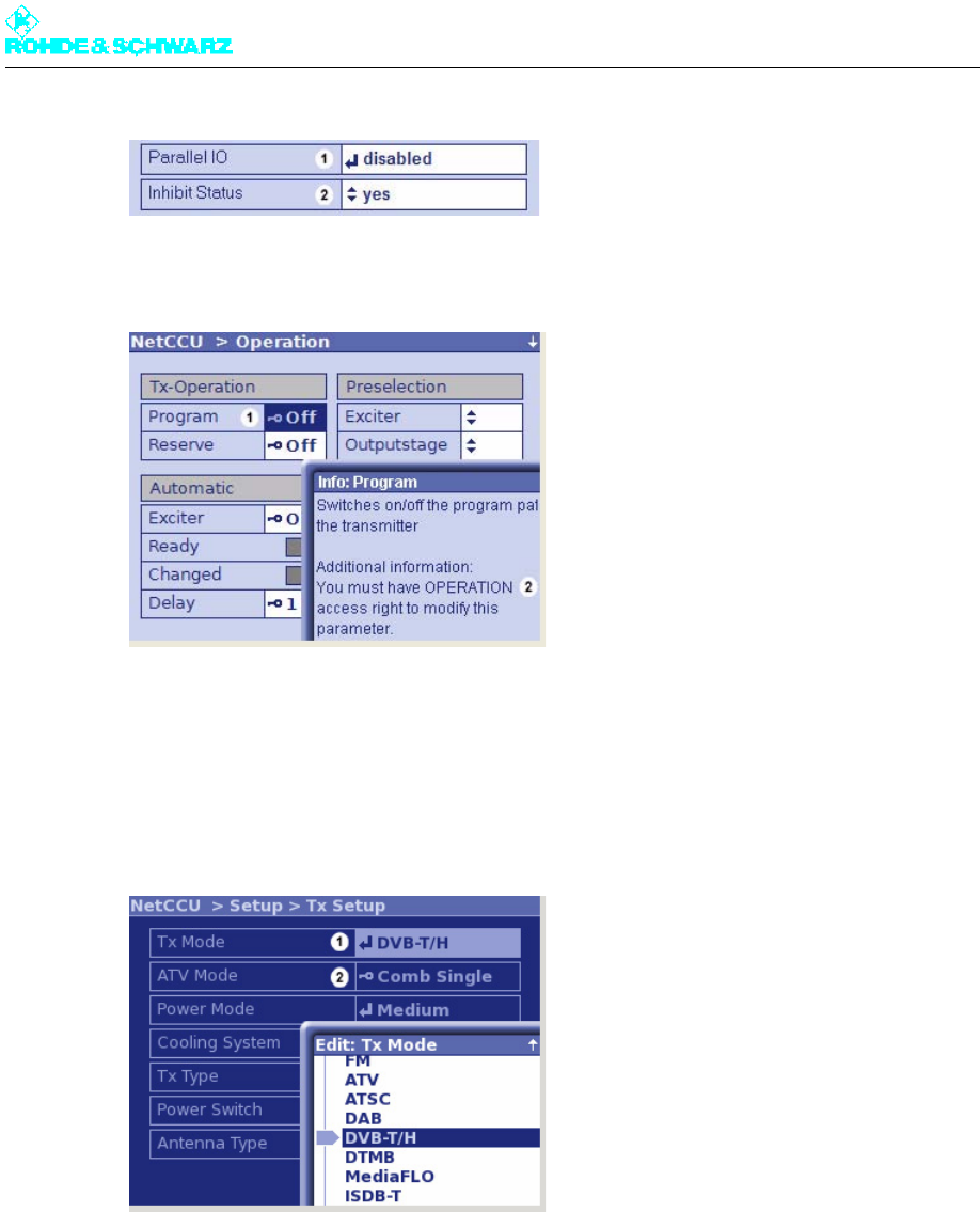
1) Setting can be changed, but the R&S NetCCU800 needs to be restarted
2) Setting can be changed; a change takes effect straight away
1) Due to insufficient user rights, the selected parameter cannot be changed at this time
2) Operation access rights are needed in order to change this setting
Selecting entries
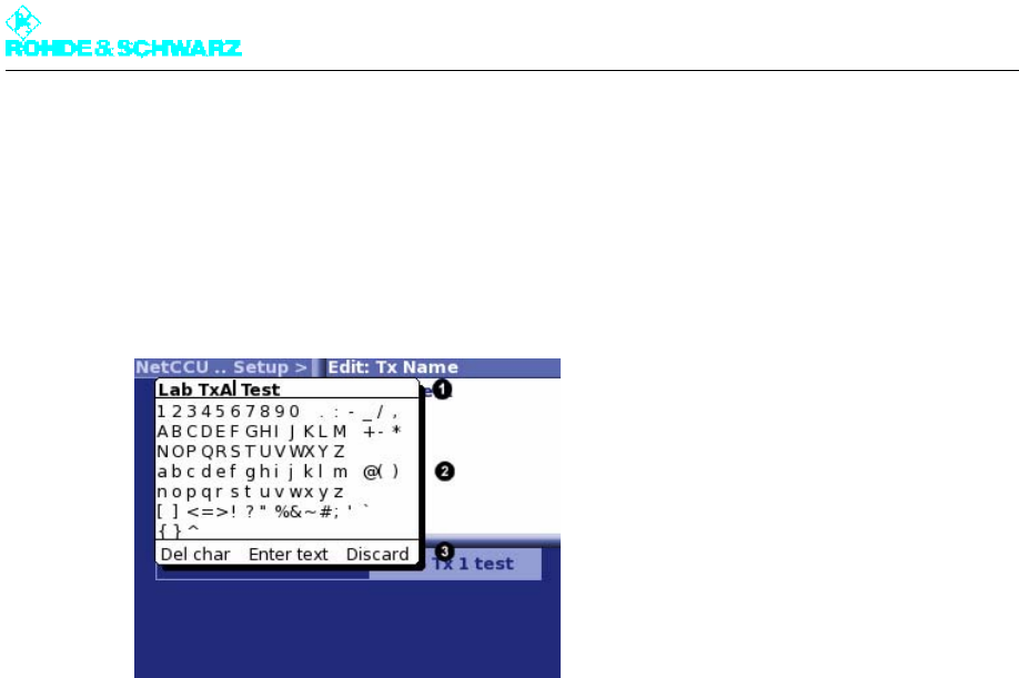
The Edit ... selection window is displayed as soon as you click OK to confirm a field that
provides a choice.
1) The entry can be edited.
2) The entry cannot be edited (no authorization (logon) or setting not possible in this constellation)
1. Using the cursor keys (up/down), select an entry in the Edit ... selection window.
2. Confirm the selection with OK.
Your selection is saved and the Edit ... selection window closes.
Use the HOME key to finish editing the menu.
Chapter 5 Operating
2098.0720.72 - 5.6 - E-2
Editing entries
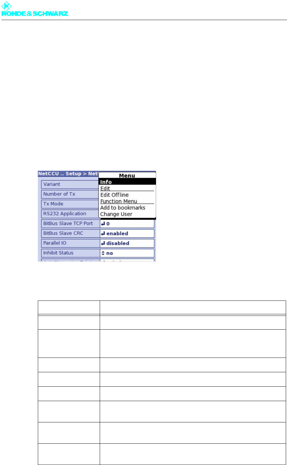
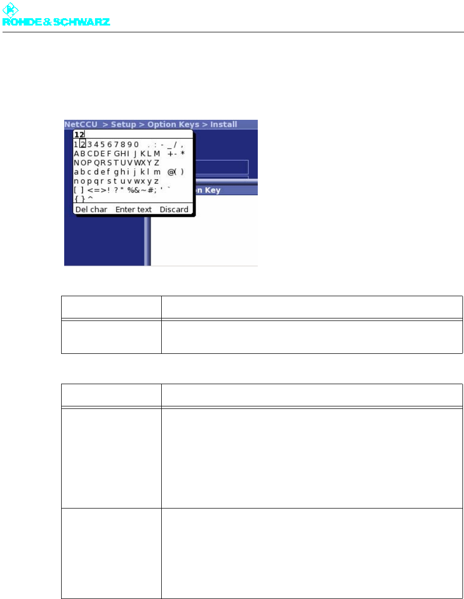
The editor is displayed as soon as you click OK to confirm a field that can be used to enter
customized text or numbers.
Note The "Selectable characters" area of the editor only ever offers you the characters needed
for the box you selected (e.g. only numbers and a point for entering an Ethernet address).
1) Entry line
2) Selectable characters
3) Command line
Entering characters:
1. Use the arrow keys to place the cursor at the desired position on the "entry line".
2. Using the cursor keys, select the required character from the "Selectable characters"
area and confirm with the OK key.
The selected character appears in the "entry line".
Deleting characters:
1. Use the arrow keys to place the cursor at the desired position on the "entry line".
2. Use the cursor keys to select Del Char from the "command line" and confirm with OK.
Characters in the "entry line" are deleted starting at the cursor position and going from
right to left.
Saving or rejecting changes:
1. To save changes (current entry in the entry line), use the cursor keys to select Enter text
from the "command line" and confirm with OK.
Your changes are saved and the editor closes.
Note If you want the editor to stay open after saving (e.g. when testing settings), select Fix
Editor from the context menu. The editor then stays open until you close it by pressing
the Back key.
Chapter 5 Operating
2098.0720.72 - 5.7 - E-2
or
To close the editor without saving the changes, use the cursor keys to select Discard
from the "command line" and confirm with the OK key.
The editor closes and your changes are not saved.
Use the HOME key to finish editing the menu.
1.1.2.3 Context Menu
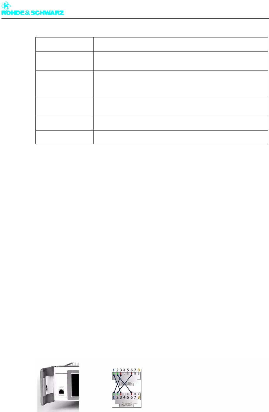
The context menu contains function- and content-oriented commands which can be applied
to the currently displayed menu.
The context menu can be called from any position using the MENU key.
You can find the content-oriented commands in the description for the menu window con-
cerned. The function-oriented commands are listed and described below:
Command Explanation
Change User Used to change the user profile
Info Help text for the menu window or menu entry concerned; also, in the
case of menu entries, information on which user rights are needed in
order to make changes
Open Used to open a menu/menu window (alternative to the OK key)
Edit Used to edit a menu item (alternative to the OK key)
Submit Changes Used to save changes made offline
Edit Online Used to edit a menu item online; standard setting which can only be
changed by selecting Edit Offline
Enter Text In editor only: Used to save entries (alternative to the 'Enter text' com-
mand in the editor command line)
Discard In editor only: Used to discard entries (alternative to the 'Discard' com-
mand in the editor command line)
Chapter 5 Operating
2098.0720.72 - 5.8 - E-2
1.2 Remote Operation or Remote Control
Remote control (e.g. via a network) and remote operation (e.g. via a PC) both require a web
browser.
Note Depending on their rights, logged-on users can monitor the transmitter in question or con-
trol all of its functions. There is no difference between remote operation and remote control
with respect to this functionality.
As standard, the R&S NetCCU800 contains the necessary components for remote opera-
tion and remote control:
Network connector (10/100 Mbit)
Network card (RJ-45)
RJ-45 crossover cable
1.2.1 Installation and Configuration
Connecting a PC/network client
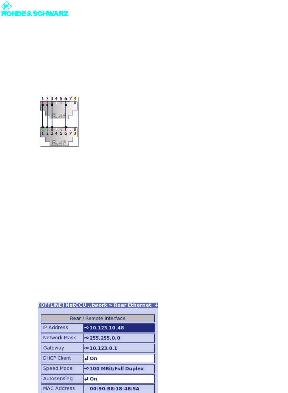
1. Using an RJ-45 crossover cable, connect the Ethernet socket on the front panel of the
R&S NetCCU800 to a local PC.
Fig. 2 Ethernet link using a crossover cable connection
Fix Editor In editor only: The editor remains open for further editing after entries
have been saved or discarded
Add to bookmarks The current menu window is saved as a bookmark; the menu windows
can be opened directly using the menu item "Bookmarks" in the Status
window
Bookmarks (in Sys-
tem Overview only)
In System Overview only: Menu windows saved as bookmarks can be
opened directly
Trigger Used to trigger a change (same as OK key)
Function Menu Used to display the Status > Tx Status menu
Command Explanation
Chapter 5 Operating
2098.0720.72 - 5.9 - E-2
or
Using an RJ45 1:1 cable, connect the X100A socket on the transmitter roof to the station
network.
Network clients can communicate with the transmitter via the NETLINK interface (X5),
which is connected to X100A, on the rear panel of the R&S NetCCU800.
Fig. 3 Link to a network using an RJ-45 1:1 cable connection
Entering IP address at R&S NetCCU800
Before you can use a browser to connect to the R&S NetCCU800 via the connector on the
rear panel of the R&S NetCCU800, you must enter the IP address required for communi-
cation directly via the front panel of the R&S NetCCU800 or have the IP address assigned
automatically. To permit this, the R&S NetCCU800 must be set to local mode (press the Lo-
cal key so that the appropriate LED lights up).
The parameters for connection to the front panel of the R&S NetCCU800 are preset and
cannot be changed.
Note The R&S NetCCU800 has an integrated DHCP client to allow automatic address assign-
ment. For automatic integration into a network, the network must contain a DHCP server.
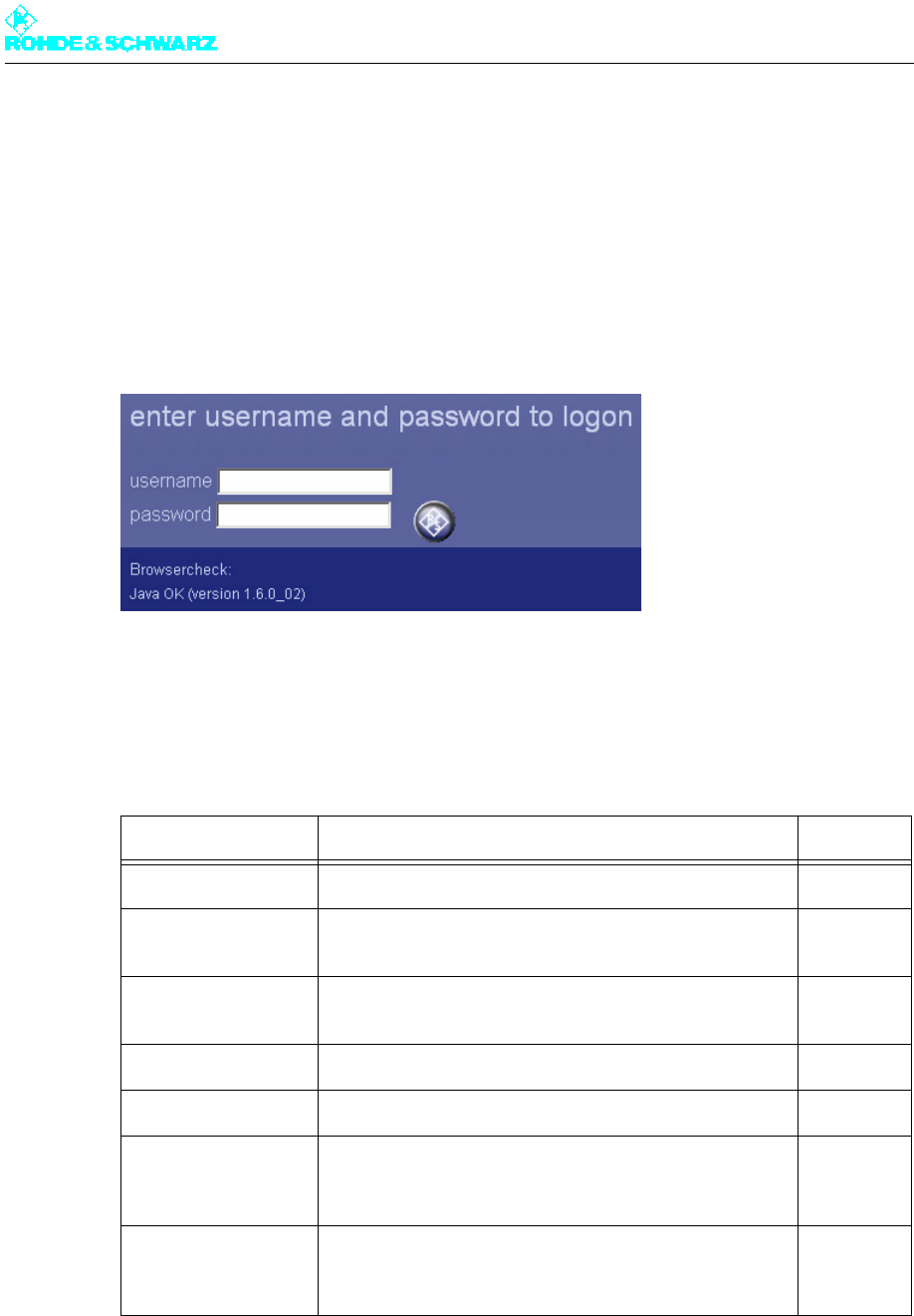
1. Select the menu NetCCU > Setup > NetCCU Setup > Network > Rear Ethernet at the
front panel of the R&S NetCCU800.
Fig. 4 Entering IP address data
2. From the context menu, select the Edit Offline mode.
3. To assign the required IP address data automatically, select the ON switch position un-
der DHCP Client.

Chapter 5 Operating
2098.0720.72 - 5.10 - E-2
or (for manual entry)
Select the OFF switch position under DHCP Client and enter the parameters IP Ad-
dress, Subnet Mask and Gateway.
4. In the context menu, select Submit Changes.
The changes will be made.
Configuring the browser
Before you can operate the R&S NetCCU800 via your browser, the following conditions
must be satisfied:
– Javascript must be enabled.
– "Java Platform Standard Edition" must be installed and activated.
Note If you are still using an older software version on the R&S NetCCU800, you may sometimes
have to enable setting of cookies. From version 1.11.0 and higher, however, this is no longer
necessary.
The next section uses Microsoft Internet Explorer to explain how you can check whether
these conditions have been met or what changes you need to make.
Note Please note that the settings described here need not necessarily match your current
browser settings one hundred percent.
The necessary changes and settings can be found in the Tools > Internet Options menu
on your Internet Explorer.
Checking and adapting the settings for Java Applets
1. Select the Security tab.
2. For the Internet zone select the Custom Level option.
3. In the tree structure go to Scripting > Scripting of Java applets and select the Enable
option.
Installing Java (Sun) JRE if necessary; checking and adapting the settings
1. Select the Advanced tab.
2. Check whether the entry Java (Sun) JRE ... is present and enabled.
3. If necessary, download and install (standard installation) the Java Runtime Environment
from the Sun website "www.java.com".
4. Then select the Internet Explorer's Advanced tab again and check whether the software
is installed and enabled.
ATTENTION!
Please note that the modified settings described here may adversely affect the security of
your Internet connections.
Chapter 5 Operating
2098.0720.72 - 5.11 - E-2
Launching program
Note To be able to operate the R&S NetCCU800 via a PC connected to the front panel, the R&S
NetCCU800 must be set to local mode (press the Local key so that the appropriate LED
lights up).
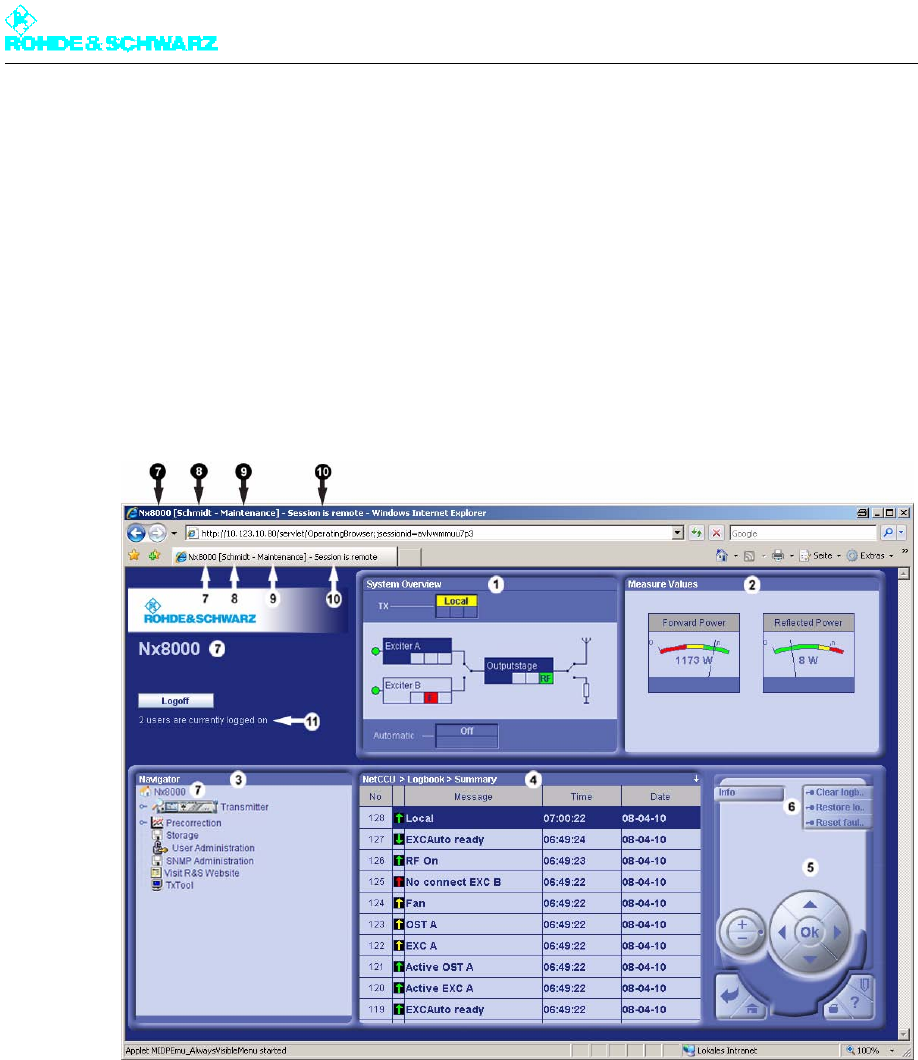
1. Start the browser on your PC or client.
2. Enter the same IP address as you entered at the R&S NetCCU800.
The login screen appears.
3. Log on using the ID you require and confirm with OK.
The corresponding entry screen appears.
Factory-set user IDs
Note The IDs Superuser and Guest are only available for the web browser.
Can't log on?
Logging on can fail for the following reasons:
User ID Authorization Password
Configuration Allows you to set basic transmitter parameters; e.g. setup 1234
Maintenance Allows you to perform maintenance tasks; e.g. software
update
1234
Operation Allows you to make settings that directly affect transmitter
operation
1234
Query Read-only authorization 1234
Guest Read-only authorization – see Query 1234
Config-Engl Same as Configuration authorization; this ID also
changes the menu language to English (irrespective of
the preset language, e.g. Chinese)
1234
Superuser For configuring, creating and deleting user profiles, and
for displaying and deleting active sessions; no authoriza-
tion for setting transmitter parameters – see Query
1234
Chapter 5 Operating
2098.0720.72 - 5.12 - E-2
– Three other users already logged on via the web browser. The maximum permitted num-
ber of simultaneous sessions has been reached. On the other hand it is always possible
to log on as Superuser.
– Incorrect ID and/or password entered.
After three failed attempts at logging on, the requesting IP address is prevented from
logging on for 30 minutes.
1.2.2 Browser-Based Operation
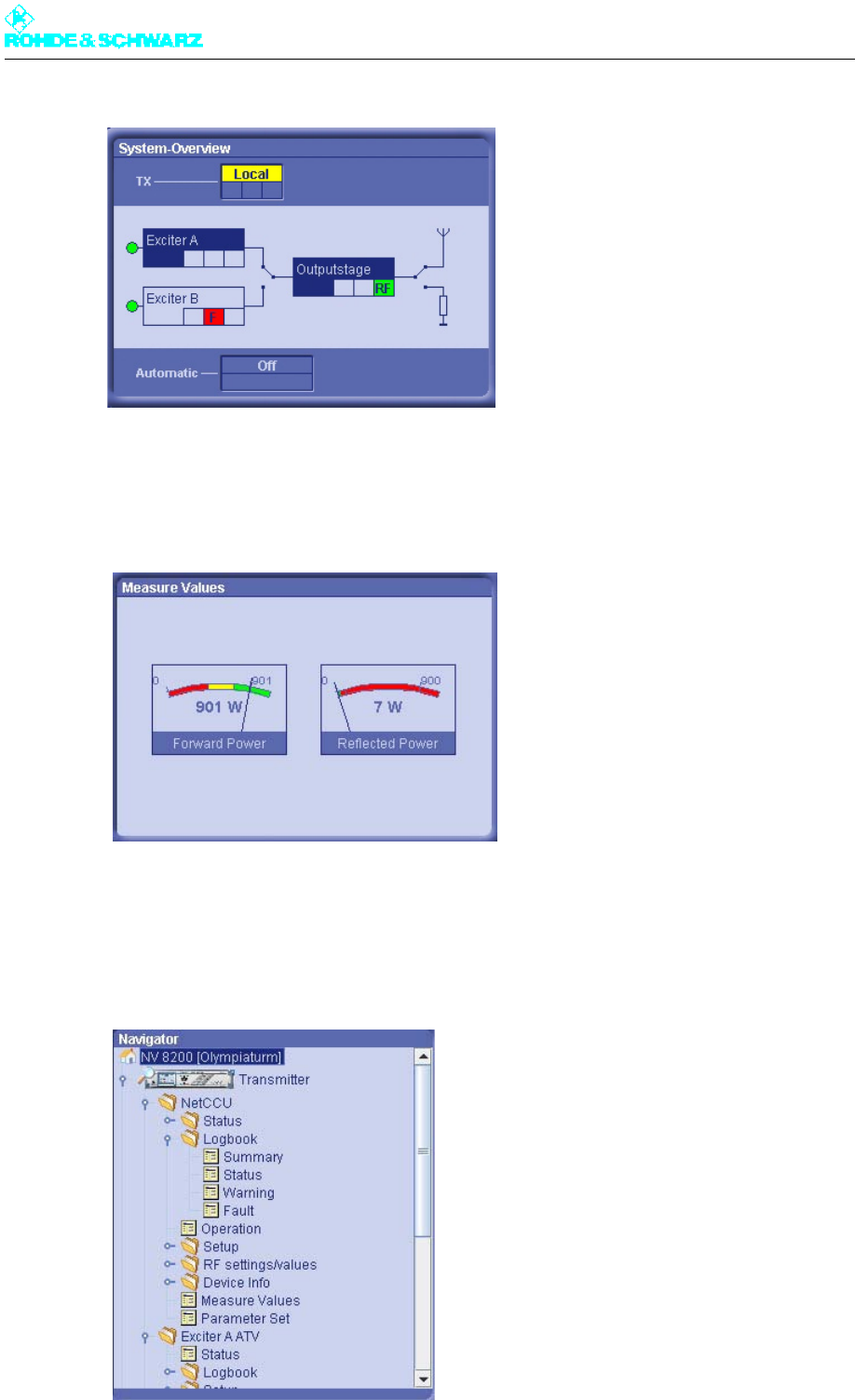
When you log on, the following entry screen will appear:
1) System Overview: current transmitter status
2) Measure Values: display of the forward and reflected power
3) Navigator: display and navigation through the transmitter menus
4) Menu window: displays the menus selected in the navigator
5) Control panel: Elements for navigating within the menu system and displaying and editing menu entries
6) Context menu (in this example the remotely logged on user cannot run any commands (key symbol), since
the R&S NetCCU800 is in local mode)
7) Transmitter name display
8) User name display (according to login details)
9) Group membership display (authorization level)
10) Session type display: In the case of "Session is remote" the user logged on via the remote Ethernet port; in
the case of "Session is local" the user logged in via the local Ethernet port
11) Total number of users logged on via web browser
System Overview
The System Overview window provides an overview showing the current status of the
transmitter and its components.
Chapter 5 Operating
2098.0720.72 - 5.13 - E-2
Measure Values
The current forward power and reflected power are displayed in the Measure Values win-
dow.
Navigator
The Navigator shows the menus of all transmitter components. You can open individual
folders or menus under Transmitter by double-clicking them. The selected menus are dis-
played in the menu window.
Chapter 5 Operating
2098.0720.72 - 5.14 - E-2
You can also call up the following functions in the Navigator:
Menu window
The menu selected in the Navigator window is displayed in the menu window.
Function Explanation
Bookmarks Display of all bookmarks: you can go directly to the selected menu win-
dow by double-clicking or by selecting Open in the context menu
Transmitter Starts operation of the transmitter menu
Precorrection Initiates calibration of the exciters
Storage Saves and imports the parameter settings
Backup / Restore Externally backs up and restores the system settings (including operat-
ing system)
User Administration Calls up the user administration function
SNMP Downloads and saves MIBs
Language Properties Downloads, installs and uninstalls customer-specific language versions
Visit R&S Website Link to the R&S website
Legal Notices Information regarding license agreements
TxTool Calls up the TxTool
Chapter 5 Operating
2098.0720.72 - 5.15 - E-2
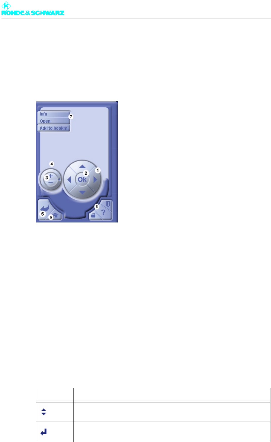
1) Double-arrow symbol: The entry can be changed
Control panel
You can use the control panel to navigate within the menu structure and menus and to
change settings in the menu window. You can activate the individual control elements with
the mouse or keyboard.
1) For switching between menu entries, for accessing editable values and for entering numerical values; each
click on the cursor keys (up/down) increments or decrements the number (corresponding to the cursor keys
on the keyboard)
2) For editing (change to editing mode) and confirming settings (corresponds to the enter key on the keyboard)
3) Corresponds to the UP and DOWN cursor keys
4) Used for quickly switching between menu items, for quickly accessing editable values and for quickly entering
numeric values; can be rotated using the mouse
5) Generally used to move one level back in the menu structure; also used to cancel settings that have not yet
been confirmed with OK
6) Return to home menu
7) Displays the context menus for the current menu window or menu item (standard context menus: Info: help
texts together with, in the case of menu items, information on which user rights are needed in order to make
changes; Open: opens a menu or menu item; Edit: for editing an entry; Edit Offline: the item can be edited
without the change being applied immediately; Submit Change: submits an item edited offline); see also Con-
text Menu under Local Operation
8) Not enabled in this software version
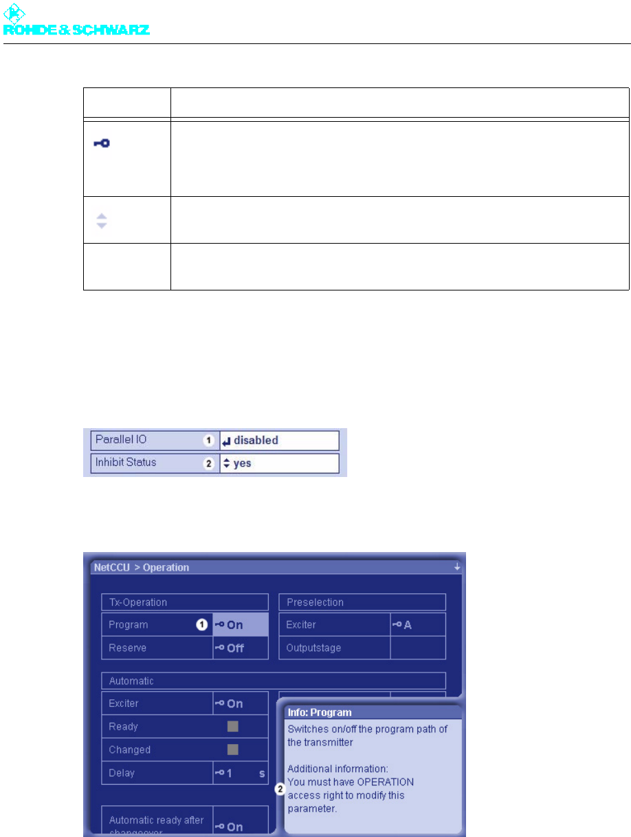
Locked and variable settings
Depending on the user rights concerned and the type of access (local or remote access)
some or all processing parameters can be locked. These include restrictions arising from
the actual constellation chosen. An appropriate symbol in front of the parameter value
shows whether or not a parameter can be changed at this time.
Symbol Meaning
The present user can change the setting. A change takes effect straight away.
The present user can change the setting. For the change to take effect, a restart
of the R&S NetCCU800 a) (and possibly the exciter b)) must be carried out.
Chapter 5 Operating
2098.0720.72 - 5.16 - E-2
Examples:
1) Setting can be changed, but the R&S NetCCU800 needs to be restarted
2) Setting can be modified; any change will take effect immediately
1) The selected parameter cannot be modified at this time (due to insufficient user authorization)
2) Operation rights are needed to modify the setting
1.2.2.1 End of Session
Use the Logoff button to log off from the system correctly. If you close the browser window
without logging off, the session is automatically terminated after two minutes at most.
If the present connection was cut (e.g. because the unit was restarted), a popup window
tells you that you need to log on again. Logging on again opens a new session.
The setting cannot be changed at the present time. Possible reasons:
– The user does not have the necessary rights. c)
– Access is via the remote port when the R&S NetCCU800 is in local mode.
– Access is local when the R&S NetCCU800 is in remote mode.
Setting is not possible in this constellation.
- none - This parameter value is for a display; it cannot be set.
a) To restart the R&S NetCCU800, run the Restart command in the SW Maintenance context menu.
b) If the parameter identified in this way is a setting for the exciter (Exciter ..... menu path), the exciter must be
restarted and then the R&S NetCCU800. To restart the exciter, run the Reboot Tx command in the Tx Setup
context menü (Exciter menu).
c) The Info command from the context menu gives information on the necessary user rights among other
things.
Symbol Meaning

Chapter 5 Operating
2098.0720.72 - 5.17 - E-2
Note The IP address displayed in the popup window can vary depending on the system and set-
ting.
1.3 User Administration
The user administration facility is available in conjunction with browser-based operation.
The settings that you make in the user administration facility are (provided that no password
is required) also valid for menu access via local operation.
You can use the user administration facility to
– change user profiles (users and access rights)
– create new user profiles
– delete user profiles
– close active sessions
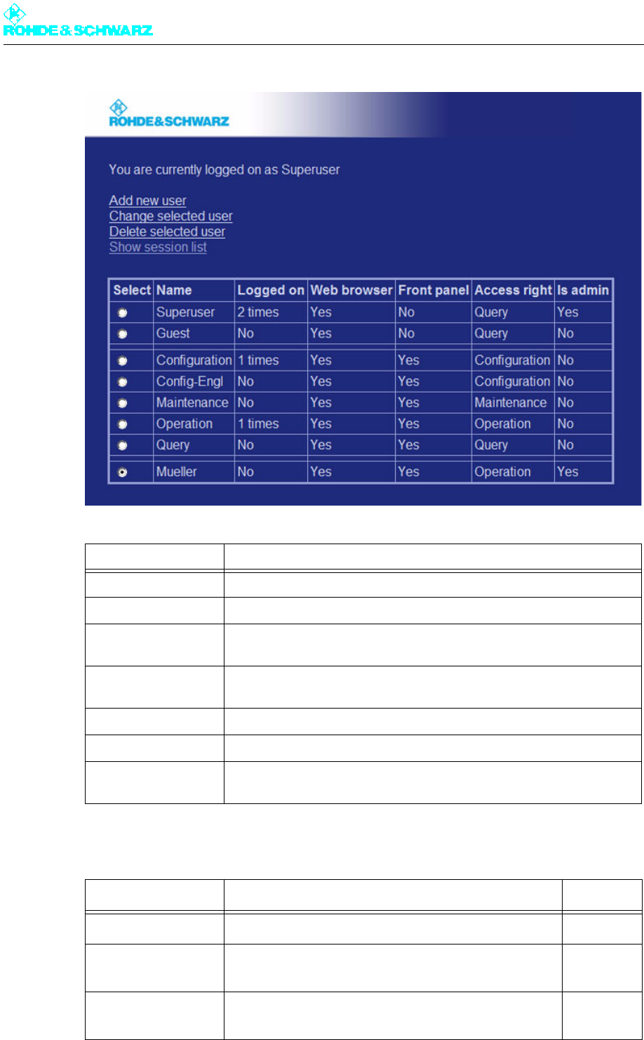
The ID Superuser with the factory-set password 1234 gives you extensive user adminis-
tration rights.
1. Log on as Superuser.
2. Select User Administration in the Navigator window.
The processing options and a list of existing users are displayed.
Chapter 5 Operating
2098.0720.72 - 5.18 - E-2
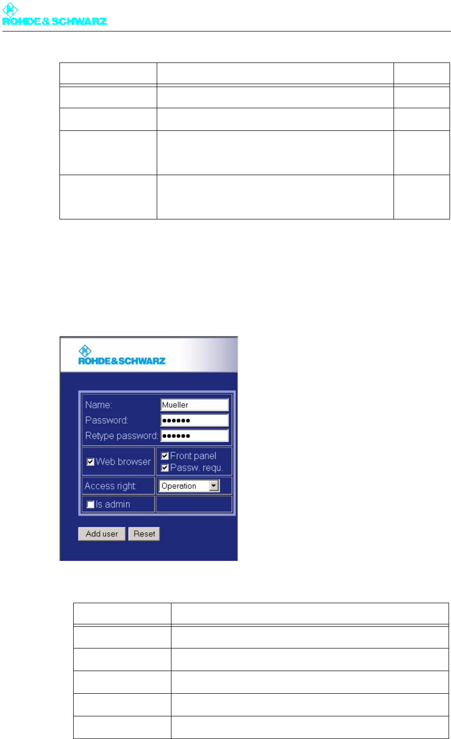
The following users are factory-set. Only the password can be changed for these users.
Display Meaning
Select Selects the user to be processed
Name User ID
Logged on The user is not logged on (No) or is logged on once/several times (X
times) at the system
Web browser The user ID and authorization permit operation via the web browser
(Yes, No)
Front panel The user ID and authorization permit local operation (Yes, No)
Access right Authorization to access transmitter parameters
Is Admin Additional user administration authorization (configuration, creation and
deletion of user profiles)
User ID Authorization Password
Configuration Allows you to set basic transmitter parameters; e.g. setup 1234
Maintenance Allows you to perform maintenance tasks; e.g. software
update
1234
Operation Allows you to make settings that directly affect transmitter
operation
1234
Chapter 5 Operating
2098.0720.72 - 5.19 - E-2
1.3.1 Creating, Changing and Deleting Users
Creating users
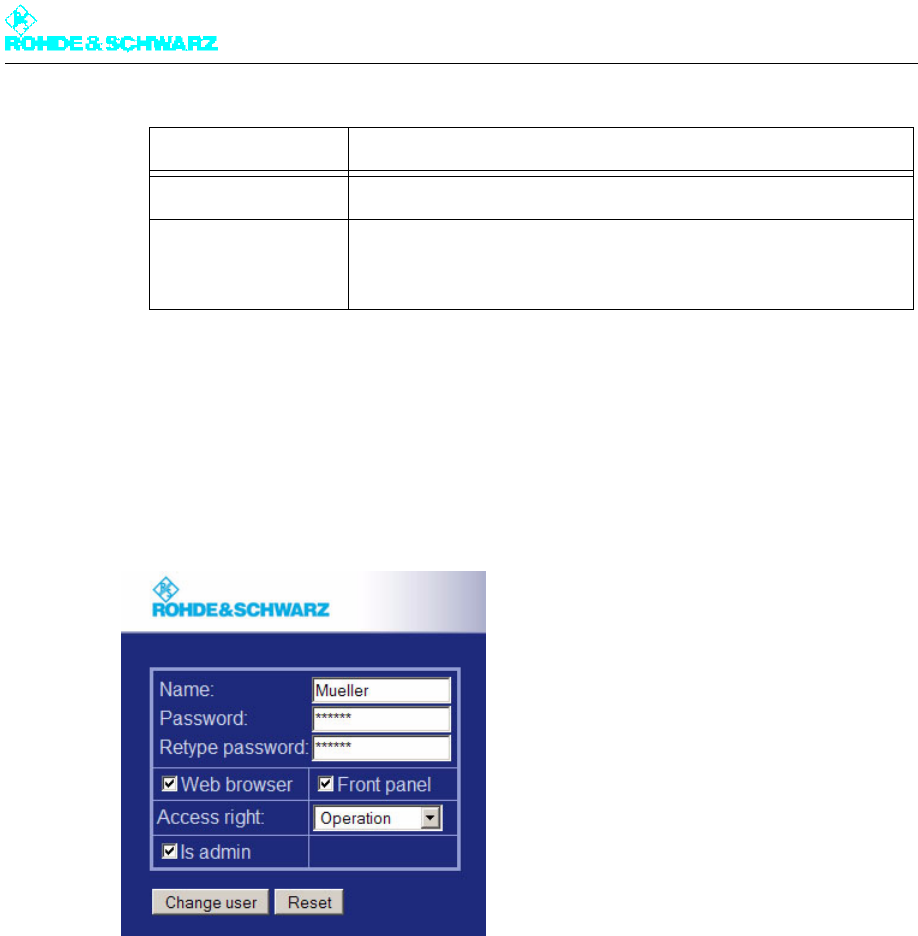
1. Select Add new user.
2. Create the required user profile.
Query Read-only authorization 1234
Guest Read-only authorization – see Query 1234
Config-Engl Same as Configuration authorization; this ID also
changes the menu language to English (irrespective of
the preset language, e.g. Chinese)
1234
Superuser For configuring, creating and deleting user profiles, and
for displaying and deleting active sessions; no authoriza-
tion for setting transmitter parameters – see Query
1234
Entry/selection Explanation
Name: User ID (case-sensitive)
Password: Must be at least 6 characters in length (case-sensitive)
Retype password: Enter the password again (case-sensitive)
Web browser The user ID permits menu access via the web browser
Front panel The user ID permits local operation
User ID Authorization Password
Chapter 5 Operating
2098.0720.72 - 5.20 - E-2
3. Confirm your entries with Add user; clicking Reset discards your entries.
Changing users
Note All users have the right to change their own password.
1. Mark the required user.
2. Select Change selected user.
3. Change the user profile in the way described under "Creating users".
4. Confirm your changes with Change User; clicking Reset discards your changes.
Deleting users
1. Mark the required user.
2. Select Delete selected user.
The user is deleted.
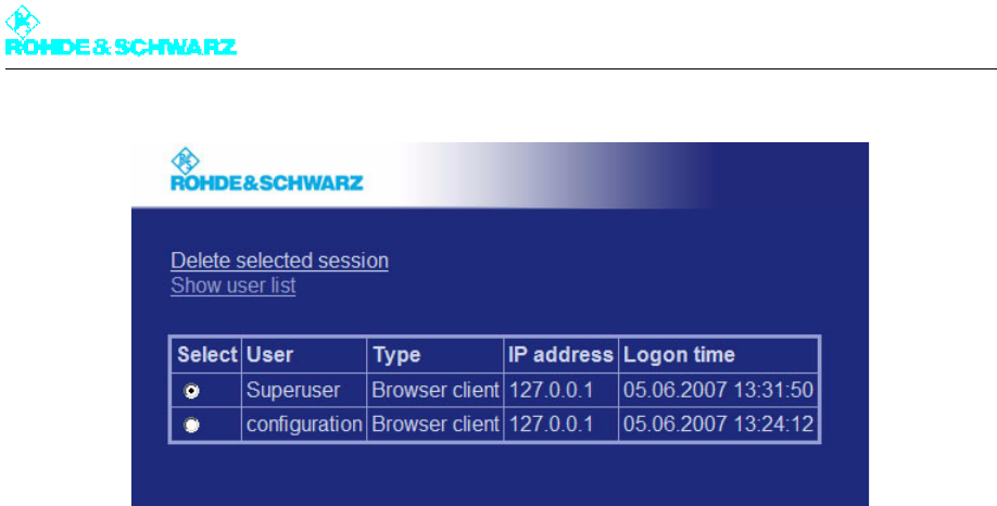
1.3.2 Closing Active Sessions
If you are logged on as Superuser, you can view detailed information on logged-on users
and close active sessions.
1. After logging on, select Show session list.
Access right Selects a factory-set authorization level
Is admin The user is also given user administration rights (configuration, cre-
ation and deletion of users; no access to the user profiles Super-
user and Guest)
Entry/selection Explanation
Chapter 5 Operating
2098.0720.72 - 5.21 - E-2
2. Mark the session (the user) that you want to close.
3. Select Delete selected session.
The marked session is closed.
4. Return to the previous browser window by clicking Show user list.
1.4 Monitoring and Control via SNMP
SNMP (Simple Network Management Protocol) is used for monitoring and controlling a
wide variety of different units in a network. Detailed information about this topic can be
found under http://www.wikipedia.org/.
A description of the unit - the MIB (Management Information Base) - must be loaded in the
central unit ("manager") from which the transmitters are monitored.
A monitored unit contains a program ("agent") which can answer queries from the manager
and execute commands. Furthermore, the agent may of its own accord generate a mes-
sage and send it to the manager. In this way, the central unit can be informed of a fault.
1.4.1 Installation
The MIBs required for monitoring and controlling a transmitter are stored as a ZIP archive
directly in the transmitter control unit and can be downloaded from there using any network-
compatible unit. All of the information required for configuration is contained in the MIBs
themselves.
When the transmitter is put into operation, both the agent in the transmitter and the manag-
er must be configured. Additional steps may be necessary if the transmitter is connected
via routers, firewalls or similar devices as they may block data packets.
The XX8000 transmitter family supports the versions SNMPv1 and SNMPv2c.
Alarms can be sent as v1Traps, v2Traps or v2Informs.
Chapter 5 Operating
2098.0720.72 - 5.22 - E-2
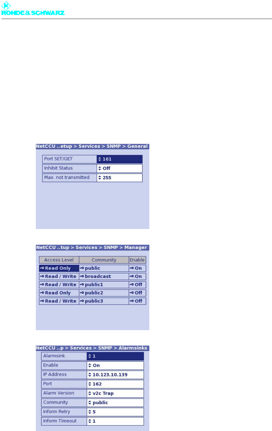
Several destinations can be set for fault messages (alarm sinks).
Several communities can be set with Read Only authorization and Read/Write authori-
zation.
1.4.1.1 Settings on Transmitter Side
You can make settings yourself via the local display (if available), the web server or SNMP.
The menu windows of the SNMP menu contain all the settings that are required for access-
ing a transmitter.
Note Changes to these settings are adopted immediately. The device does not need to be re-
started.

Chapter 5 Operating
2098.0720.72 - 5.23 - E-2
Note Detailed information about the individual parameters can be found in the descriptions of the
respective menu windows.
1.4.1.2 Settings on Manager Side
To be able to monitor and control a transmitter with SNMP, the MIB of the device and a pro-
gram which can interpret the MIB must be available on the manager side.
You can load all available MIBs from any device using a web browser.
1. Log on using the web browser and select the SNMP Administration menu.
MIBs from Rohde&Schwarz and IRT are available. MIBs from IRT allow transmitters to
be linked using SNMP irrespective of the manufacturer. They are, however, limited with
respect to their functionality. When using IRT MIBs, you can select the "Inhibit Status"
for local operation (in the same way as for the parallel contacts). If this function is acti-
vated, no alarms/traps are sent when the transmitter is in local mode. You can activate/
deactivate this function using Inhibit Status in the SNMP > General menu window.
The MIBs have the naming convention RS-XX8000-<TV/Radio Standard>-<Standby
Concept/Option>-MIB. An example is RS-XX8000-ATV-TX-MIB for signal transmitters
for analog TV.
Examples of MIBs and contents:
MIB Description
RS-COMMON-MIB Contains general Rohde&Schwarz definitions
RS-XX8000-COM-
MON-MIB
Contains definitions which all XX8000 transmitters fulfill (e.g. type
plate, configuration)
RS-XX8000-DVB-TX-
MIB
Contains definitions for DVB single transmitters, passive exciter
standby, active and passive output-stage standby
RS-XX8000-DVB-
NP1-MIB
Contains definitions for DVB n+1 systems
RS-XX8000-DVB-
NTX-MIB
Contains definitions that an R&S NetCCU800 provides as access for
n different, independent DVB transmitters
RS-XX8000-DVB-TX-
REC-MIB
Contains definitions for the optional DVB receiver in a transmitter
RS-XX8000-DVB-
NP1-REC-MIB
Contains definitions for the optional DVB receiver(s) in an n+1 sys-
tem
RS-XX8000-FM-TX-
MIB
Contains definitions for FM single transmitters with passive exciter
standby and active and passive output-stage standby
RS-XX8000-FM-NP1-
MIB
Contains definitions for FM n+1 systems
RS-XX8000-ATV-TX-
MIB
Contains definitions for analog TV single transmitters with passive
exciter standby and active and passive output-stage standby
Chapter 5 Operating
2098.0720.72 - 5.24 - E-2
2. Save the required ZIP file to your PC.
3. Load the following MIBs:
a) RS-COMMON-MIB
b) RS-XX8000-COMMON-MIB
c) MIB of the standby concept or option
A detailed description of the MIBs, the information that they contain and the associated op-
tions is given below.
1.4.1.3 Testing SNMP Communication
SNMP communications is properly set up if you have loaded the MIBs in your program and
you are using the correct IP address of the transmitter and the correct community. For que-
ries and settings you must set the SNMP version in your manager; the transmitters detect
the used protocol automatically.
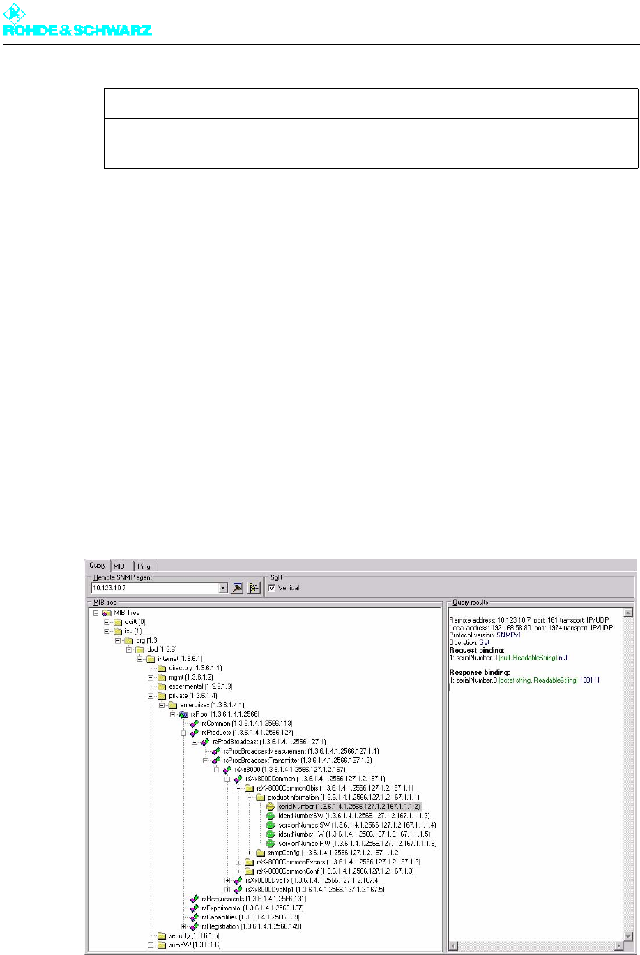
The following query can be used as a simple test:
In the example above, a transmitter with the IP address 10.123.10.7 queries the OID (Ob-
jectIdentifier: unique designation of a data point) serialNumber
(.1.3.6.1.4.1.2566.127.1.2.167.1.1.1.2). The reply from the agent is 100111.
RS-XX8000-ATV-
NP1-MIB
Contains definitions for analog TV n+1 systems
MIB Description
Chapter 5 Operating
2098.0720.72 - 5.25 - E-2
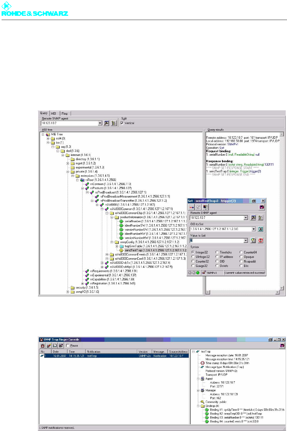
Using a further test, you can check whether the transmitter sends an alarm message in the
event of an error and whether this message reaches the alarm destinations. To do so, set
an OID sendTestTrap (.1.3.6.1.4.1.2566.127.1.2.167.1.1.2.3) to the value 2, which triggers
a testTrap (.1.3.6.1.4.1.2566.127.1.2.167.1.2.0.1). This alarm is sent to all receivers which
have been entered for the alarms (Trapsinks, see above).
This type of fault message functions in a slightly different way than that used for querying
and setting values (default: UDP Port 161 for SET/GET and UDP Port 162 for alarms).
The following illustration shows that the testTrap has been received correctly by the unit
with the serial number 100111.
Known problems
If querying the data does not work or if you do not receive an alarm, check the following:

Chapter 5 Operating
2098.0720.72 - 5.26 - E-2
– Has the network been connected correctly? Does the SNMP connection function exclu-
sively via the remote Ethernet interface of the device (R&S NetCCU800: X5 – NETLINK,
R&S Sx800/SX801: X2, R&S xLx8000: X32 – ETHERNET REMOTE)?
– Are the network settings (IP address, gateway) correct?
– Has the correct Community been entered for accessing the manager and the transmitter
(case-sensitive)?
– Is a PC firewall blocking incoming SNMP packets?
– Has the program which receives alarms been started and correctly configured?
– In large networks: Is a router or firewall blocking the SNMP packets?
– Is message suppression (Inhibit Status in the SNMP > General menu) activated?
1.4.1.4 Configuration
This chapter provides an overview of the available properties.
RS-XX8000-COMMON-MIB
This MIB contains general data that supports every unit:
– Type plate: serial number, software version, etc
– SNMP configuration: table for alarm destinations and alarm versions
– Triggering of a test trap
– Counter for counting the transmitted traps
– List of the alarm messages last transmitted
– Parameters which are used in several other MIBs
This information always applies to the instrument that is being monitored via SNMP.
RS-XX8000-DVB-TX-MIB
This MIB contains the parameters for:
– the standby concepts "single transmitter", "passive exciter standby", "active output-
stage standby" and "passive output-stage standby"
– all power classes (low-power, medium-power and high-power)
– air-cooled and liquid-cooled transmitters
Different parameters are available depending on the system being queried. For example,
cmdTxOpModeExcAutomatic (.1.3.6.1.4.1.2566.127.1.2.167.4.1.1.1.7) gives the reply
NoSuchName if you query a single transmitter since this transmitter does not have an au-
tomatic exciter function. It is easy to find out which parameters are valid by checking the
"module compliances" (e.g. under .1.3.6.1.4.1.2566.127.1.2.167.4.5.2).
Example: DVB configuration, passive exciter standby, medium power, optional DVB receiv-
er module with two inputs.
Valid MIBs:
Chapter 5 Operating
2098.0720.72 - 5.27 - E-2
– RS-COMMON-MIB
– RS-XX8000-COMMON-MIB
– RS-XX8000-DVB-TX-MIB
– RS-XX8000-DVB-TX-REC-MIB
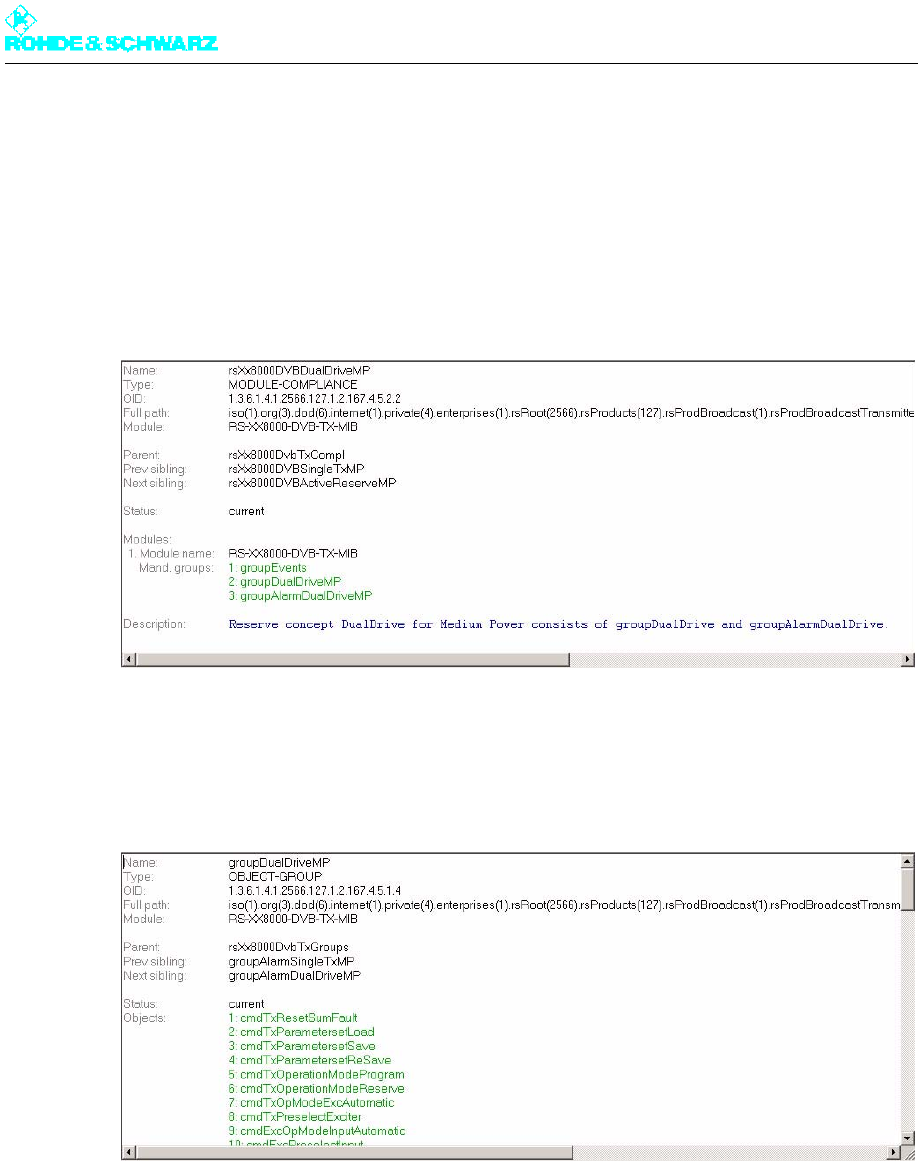
The valid OIDs for the transmitter are contained in the "Module Compliance" path. The OID
contains references to the individual groups.
Fig. 5 RS-XX8000-DVB-TX-MIB
1) Name and OID for DualDrive MediumPower
2) Reference to groupEvents - 1.3.6.1.4.1.2566.127.1.2.167.4.5.1.1
3) Reference to groupDualDriveMP - 1.3.6.1.4.1.2566.127.1.2.167.4.5.1.4
4) Reference to groupAlarmDualDriveMP - 1.3.6.1.4.1.2566.127.1.2.167.4.5.1.5
Fig. 6 List of parameters (excerpt) for groupDualDriveMP
1) Name and OID for DualTuner
2) Reference to groupDualTuner - 1.3.6.1.4.1.2566.127.1.2.167.2.5.1.3
3) groupAlarmDualTuner - 1.3.6.1.4.1.2566.127.1.2.167.2.5.1.5
The groups contain all valid OIDs. The valid OIDs for the receiver module are contained in
the "Module Compliance" path of the RS-XX8000-DVB-TX-REC-MIB. The OID contains
references to the individual groups. The groups contain all valid OIDs.
Chapter 5 Operating
2098.0720.72 - 5.28 - E-2
RS-XX8000-DVB-NP1-MIB
This MIB contains all the parameters required for any DVB n+1 system, irrespective of the
following features of the individual transmitter:
– variant
– power class
– cooling system
Once again, unavailable parameters receive the reply NoSuchName, e.g. parameters from
the transmitter A8 if only a 4+1 system is available (see module compliances under
.1.3.6.1.4.1.2566.127.1.2.167.5.5.2).
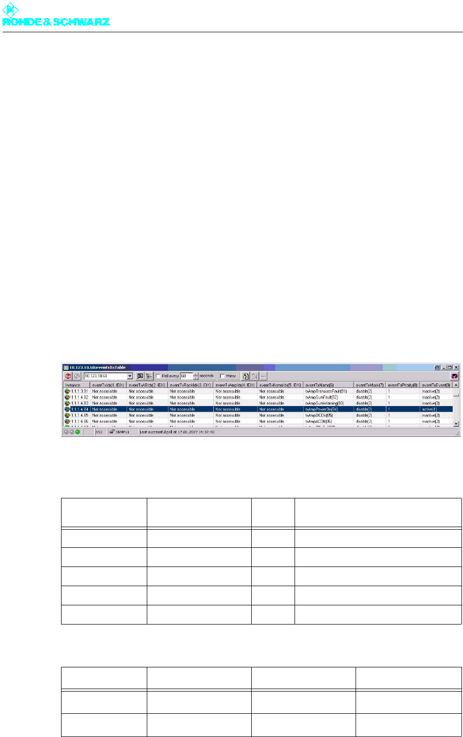
Setting alarms
The transmitter-specific alarms offer an extensive range of configuration possibilities.
Depending on the available system, it is possible to set detailed alarms: for example, for
every item of status information in every amplifier in every rack of every transmitter in a me-
dium-power n+1 system. In addition, it is also possible to assign a freely selectable priority
and to check the current status.
In the illustration above, the following information is contained in the highlighted row (de-
pending on the used MIB; here: DVB n+1 medium-power system):
Tab. 1 "Instance" column (1.1.1.4.84) in numeric order
Position of code
number Meaning of position Value Meaning of value
1 Transmitter 1 Transmitter TxB
2 Output stage 1 Output stage A
3 Transmitter rack 1 Transmitter rack No. 1
4 Amplifier 4 Amplifier No. 4
5 Event 84 Amplifier ON/OFF
Column Meaning Value Explanation
eventTxName(6) Designation of event txAmpPowerOn(84) Amplifier ON/OFF
eventTxMask(7) Message for event disable(2) No alarm is sent

Chapter 5 Operating
2098.0720.72 - 5.29 - E-2
Tab. 2 Meaning of other columns
The columns containing the value Not accessible are "index" columns (identified by IDX).
OIDs of these columns cannot be queried; they are used for internal purposes only.
Example: DVB, N+1, low power
Valid MIBs:
– RS-COMMON-MIB
– RS-XX8000-COMMON-MIB
– RS-XX8000-DVB-NP1-MIB
Valid OIDs in "Module Compliance" path for N+1 low power:
– Name: rsXx8000DVBNplus1LP
– OID: 1.3.6.1.4.1.2566.127.1.2.167.5.5.2.2
Groups:
– groupNsuLP - 1.36.1.4.1.2566.127.1.2.167.5.5.1.6
– groupAlarmNsuLP" - 1.3.6.1.4.1.2566.127.1.2.167.5.5.1.7
– groupTxLP - 1.3.6.1.4.1.2566.127.1.2.167.5.5.1.8
– groupAlarmTxLP - 1.3.6.1.4.1.2566.127.1.2.167.5.5.1.9
– groupEvents - 1.3.6.1.4.1.2566.127.1.2.167.5.5.1.5
eventTxPriority(8) Priority for event Value freely selectable
by customer
Default setting when
supplied: 1
eventTxEvent(9) Current status of
amplifier
active(1)
(inactive(2))
Amplifier ON
(Amplifier OFF)
Column Meaning Value Explanation
Chapter 5 Operating
2098.0720.72 - 5.30 - E-2
2 Menus of R&S NetCCU800
2.1 Overview of Menus
R&S NetCCU800 menu structure
Level 1 Level 2 Level 3 Level 4 Level 5
Status
Tx Status
RF Status
Device Status
Logbook
Summary
Status
Warning
Fault
Operation
Setup
TX Setup
Option Keys
Status
Install
Deactivation

Chapter 5 Operating
2098.0720.72 - 5.31 - E-2
NetCCU Setup
Common
Date / Time
System
SW
Maintenance
SW Backup/
Restore
Network
Front Ethernet
Rear Ethernet
Services
SNMP
General
Manager
Alarmsinks
NTP
RS232
ParIO Cards
Order
General
Purpose ParIO
RF Probe
Antenna
RF Vision a)
RF Sound a)
RF Probe
Forward
RF Probe
Reflected
Device Info
R&S NetCCU800 menu structure
Level 1 Level 2 Level 3 Level 4 Level 5
Chapter 5 Operating
2098.0720.72 - 5.32 - E-2
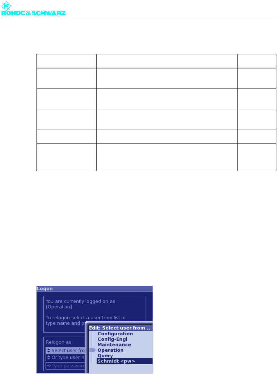
2.2 Login
Various authorization levels protect against nondeliberate access of critical system settings
from the home menu. When you start local operation via the keypad and display of the R&S
NetCCU800, your user ID is Operation by default.
Note If you have the appropriate authorization, you can change, create or delete user profiles us-
ing the user administration facility (called up via the web browser).
You can change your user ID in any menu using the Change User context menu. No pass-
word is required to change the user ID under local control (according to the factory default).
You can also protect access via the front panel by entering a password.
You can select a user profile by clicking Select user from list.
NetCCU
Mainboard
Parameter Set
a) Analog TV only
R&S NetCCU800 menu structure
Level 1 Level 2 Level 3 Level 4 Level 5
Chapter 5 Operating
2098.0720.72 - 5.33 - E-2
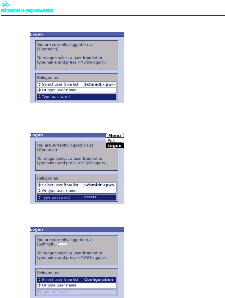
The following factory-default user profiles are available for local operation:
Change of user via the front panel by entering a password (example)
In the following example a user profile "Schmidt" has been set up in user administration.
The user has obtained authorization for local control, but must enter a password.
1. From the context menu, call the Change User command.
2. Go to Select user from list and select the user Schmidt <pw>.
The "<pw>" in angle brackets tells you that a password is needed.
3. Select the Type password command.
User ID Authorization Password a)
a) By default the password (factory setting: 1234) is needed only for browser-based operation. Every user can
change his/her own password via the user administration program.
Configuration Allows you to set basic transmitter parameters; e.g.
setup
1234
Maintenance Allows you to perform maintenance tasks; e.g. software
update
1234
Operation Allows you to make settings that directly affect transmit-
ter operation
1234
Query Read-only authorization 1234
Config-Engl Same as Configuration authorization; this ID also
changes the menu language to English (irrespective of
the preset language, e.g. Chinese)
1234
Chapter 5 Operating
2098.0720.72 - 5.34 - E-2
4. Enter the password in the editor.
5. Use the Logon command from the context menu to log on.
User "Schmidt" is then logged on:
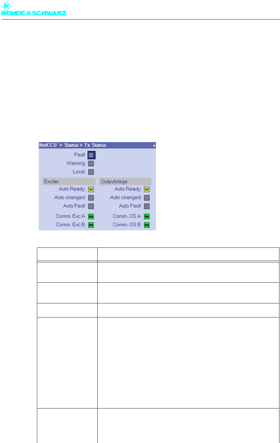
2.3 Status Menu
The Status menu provides an overview of faults, warnings and status messages relating to
the individual components and functions of the transmitter.
Chapter 5 Operating
2098.0720.72 - 5.35 - E-2
2.3.1 Tx Status Menu Window
The TX Status menu window provides an overview of faults, warnings and status messag-
es relating to the communication and standby status of the transmitter.
The TX Status menu window is divided into the following three sections (from top left to bot-
tom right):
– Sum fault / sum warning / local mode
– Status messages relating to automatic exciter switchover function
– Status messages relating to automatic amplifier-stage switchover function
Function Explanation
Fault Red: Sum message "Fault"; a fault has occurred in the transmitter sys-
tem
Warning Yellow: Sum message "Warning"; a warning message has been output
in the transmitter system
Local Yellow: R&S NetCCU800 has been switched over to local mode
Exciter
Auto Ready Green: Automatic exciter switchover function is ready
Yellow: Automatic exciter switchover function is not ready
Auto Chan. Yellow: Switchover to standby exciter; Auto Ready indicator is yellow
Auto Fault Red: A fault occurred during switchover to the standby exciter
Comm Ex. A Red: Communication error between R&S NetCCU800 and exciter A
Comm. Ex. B Red: Communication error between R&S NetCCU800 and exciter B
Outputstage
Auto Ready Green: Automatic output-stage switchover function is ready
Yellow: Automatic output-stage switchover function is not ready
Chapter 5 Operating
2098.0720.72 - 5.36 - E-2
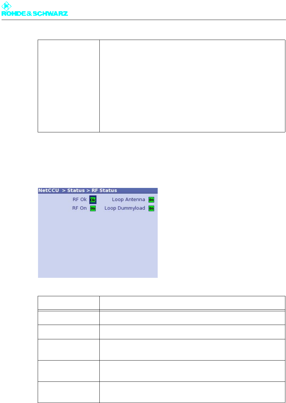
2.3.2 RF Status Menu Window
The RF Status menu window provides an overview of the transmitter's RF status.
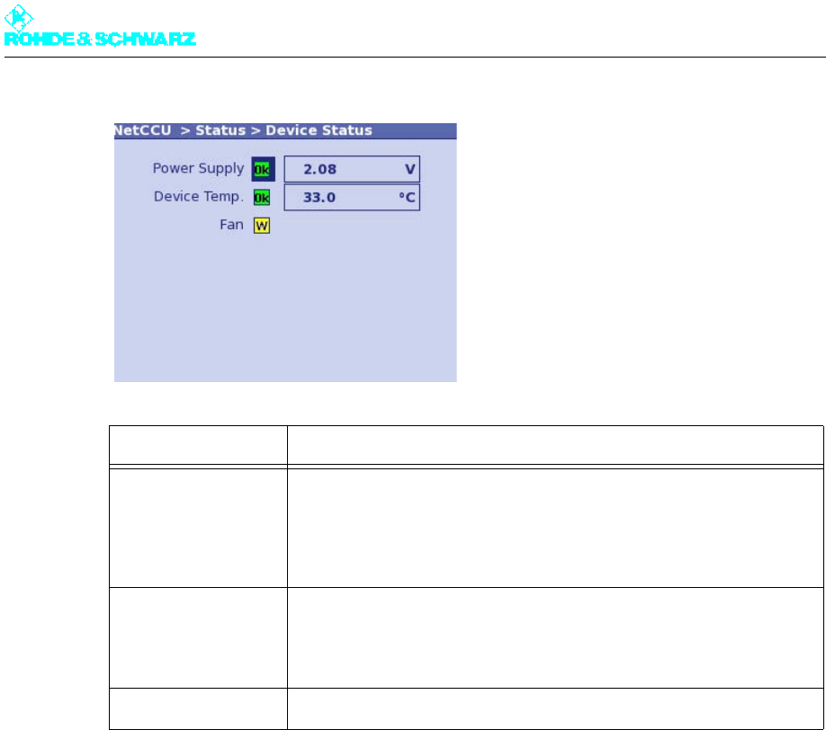
2.3.3 Device Status Menu Window
The Device Status menu window provides an overview of faults, warnings and status mes-
sages relating to the R&S NetCCU800.
Auto Chan. Yellow: Switchover to standby output stage; Auto Ready indicator is yel-
low
Auto Fault Red: A fault occurred during switchover to the standby output stage
Comm. OS. A Red: Communication error between R&S NetCCU800 and output stage
A
Comm OS. B Red: Communication error between R&S NetCCU800 and output stage
B
Function Explanation
RF On Green: Antenna output power above the set fault threshold
RF OK Green: Antenna output power above the set warning threshold
Reduced RF
(ATV only)
Yellow: Transmitter has reduced its output power
Loop Program Green: Closed operation loop
Yellow: Open operation loop
Loop Dummyload Green: Closed operation loop
Yellow: Open operation loop
Function Explanation
Chapter 5 Operating
2098.0720.72 - 5.37 - E-2
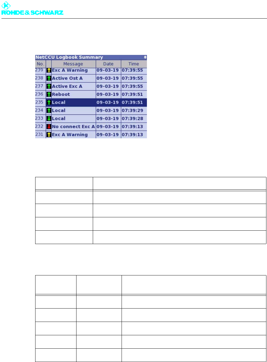
2.4 Logbook Menu
You can use the Logbook menu to query status and error messages relating to the R&S
NetCCU800, to delete these messages and to restore deleted messages. The menu win-
dows of the logbook provide an overview of the status, warning and error messages relating
to the R&S NetCCU800.
Note You can call up logbook entries in the windows Summary, Status, Warning and Fault. The
structure of the four windows is identical.
Function Description
Power Supply Red: Internal power supply of the R&S NetCCU800 has failed; other-
wise green
Right: Displays the check value of the internal voltage supply; the cor-
rect value is in the range 1.86 to 2.28 V
Device Temp. Red: Temperature inside the R&S NetCCU800 is too high; otherwise
green
Right: Displays the current temperature
Fan Yellow: Fan of the R&S NetCCU800 has failed; otherwise green
Chapter 5 Operating
2098.0720.72 - 5.38 - E-2
2.4.1 Summary Menu Window
Fig. 7 Logbook > Summary window
The following table explains the meaning of the columns:
The arrows in the second column have the following meaning:
Using the context menu, you can delete (Clear logbook) and restore (Restore logbook)
status and error messages.
Column Explanation
No Consecutive entry number
Message Message
Time Time at which the message was received
Date Date on which the message was received
Arrow direc-
tion Arrow color Explanation
Up The event has just occurred.
Down The event is no longer current or relevant.
Red Fault
Yellow Warning
Green Status
Chapter 5 Operating
2098.0720.72 - 5.39 - E-2
2.5 Operation Menu Window
In the Operation menu window you can make settings for the standby behavior and for the
exciter and amplifier.
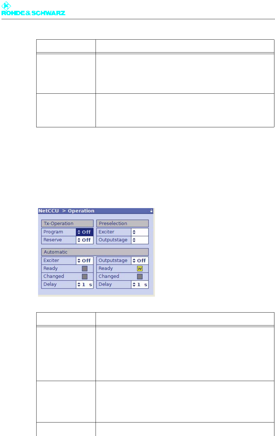
Function Explanation
Clear logbook Clears all entries in the current logbook; clearing individual logbook
entries is not possible.
When you clear the complete logbook, the partial logbooks are also
cleared. A Reset Fault is triggered at the same time.
Restore logbook Restores the cleared entries in the current logbook.
When you restore the complete logbook, the partial logbooks are also
restored.
Function Explanation
Tx-Operation
Program On/Off ON/OFF command for transmitter (exciter and output stage); corre-
sponds to the hard key on the front panel
Reserve On/Off ON/OFF command for standby transmitter
(all components that are not connected to an antenna)
Preselection
Exciter A/B Used to select the active exciter
Outputstage A/B Used to select the active output stage
Automatic

Chapter 5 Operating
2098.0720.72 - 5.40 - E-2
2.6 Setup Menu
You can use the Setup menu to configure the transmitter system's hardware.
2.6.1 Tx Setup Menu Window
In the Tx Setup menu window you can define the standby behavior and enter additional
system-specific settings.
Exciter On/Off Used to switch the automatic exciter switchover function to active or not
active
Ready Status of the automatic exciter switchover function:
Green: Automatic switchover function is ready for operation
Yellow: Automatic switchover function is ready for operation
Changed Yellow: Main exciter has been switched over to the standby exciter;
Ready indicator is yellow
Delay Delay before a switchover occurs so that a brief fault does not immedi-
ately trigger a switchover.
Outputstage On/Off
(only with passive
output-stage standby
= passive PA)
Used to switch the automatic amplifier switchover function to active or
not active
Ready Status of the automatic amplifier switchover function:
Green: Automatic switchover function is ready for operation
Yellow: Automatic switchover function is not ready for operation
Changed Yellow: Main amplifier has been switched over to the standby amplifier;
Ready indicator is yellow
Delay Delay before a switchover occurs so that a brief fault does not immedi-
ately trigger a switchover.
Automatic ready after
changeover (with
standby systems
only)
If this function is activated, the automatic function can assume the
"Ready" state again following switchover. Switchover is then possible
again.
Reset on program off If this function is activated, the OFF command also executes a reset
fault (see below).
Reset Fault (context
menu)
Used to reset fault indicators
The function has the same effect as the RESET FAULT key on the front
panel of the exciter and also belongs to the range of functions available
for remote operation via the R&S NetCCU800.
Function Explanation

Chapter 5 Operating
2098.0720.72 - 5.41 - E-2
Function Explanation
Tx Mode Used to select the transmitter standard
– NoExciter: R&S NetCCU800 is operated as a standalone instrument
(e.g. in combination with the DVB-T receiver module option)
– Multi: Both exciters in a transmitter use different standards
– FM: Analog sound broadcasting standard
– ATV: Analog TV standard
– ATSC: Digital TV standard (USA)
– DAB: Digital audio broadcasting standard
– DVB: Digital TV standard (Europe)
– DTMB: Digital TV standard (South America, Asia, Europe)
– MediaFLO™: Digital TV standard (USA)
– ISDB-T: Digital TV standard (Brazil, Japan)
ATV Mode Selection only possible if ATV is set under Tx Mode
– Comb Single: Vision signal and sound signal are transmitted via one
amplifier (same channel) (single = 1 sound carrier)
– Comb Dual: Vision signal and sound signal are transmitted via one
amplifier (same channel) (dual = 2 sound carriers)
Power Mode Used to set the power class
– Low
– Medium
– High
Cooling System Used cooling system
The following setting is preset for Power Mode "Low" or "Medium":
– Air: Air cooling
The following settings can be selected for Power Mode "High":
– Liquid: Transmitter is connected to an external cooling system which
is used to cool the entire station
– Liquid PUC: Transmitter has its own cooling system (R&S ZK810)
Tx Type Used to set the standby behavior:
– Single TX: Standby system (see below)
– Dual Drive: Standby system (see below)
– Passive PA: Standby system (see below)
– Active PA: Standby system (see below)
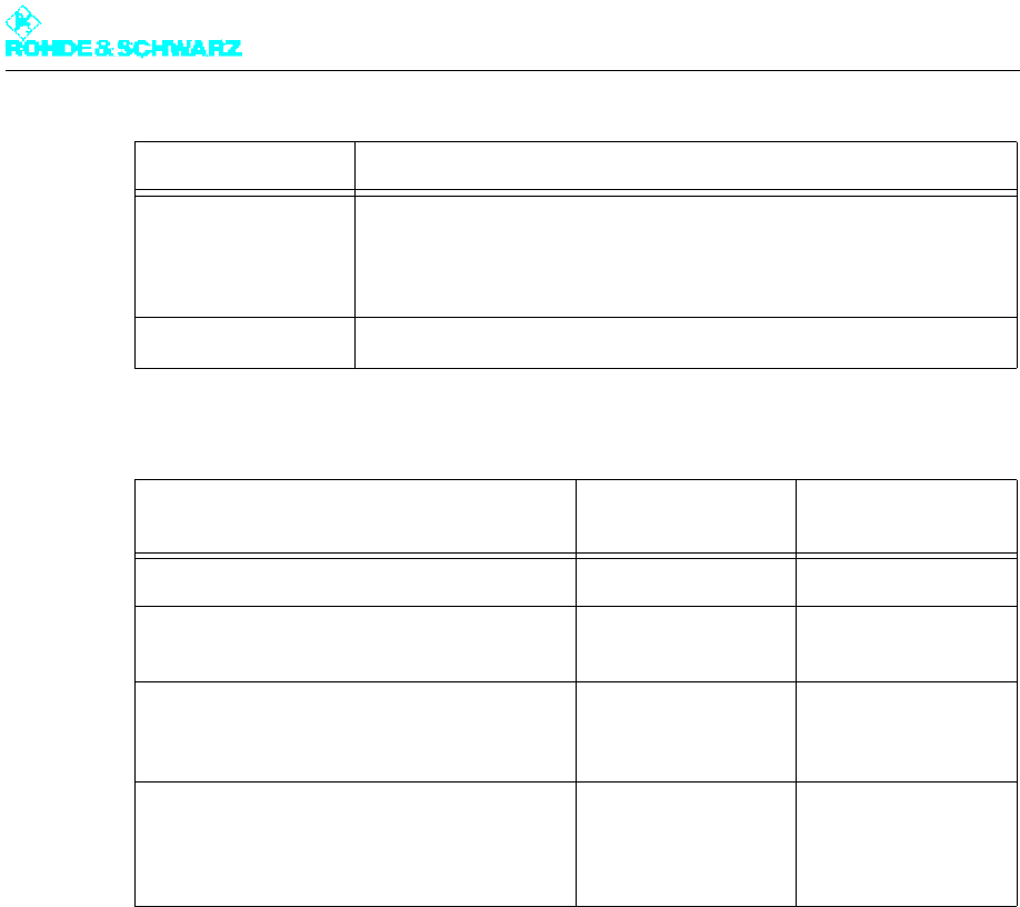
Chapter 5 Operating
2098.0720.72 - 5.42 - E-2
Basic setup of transmitter standby systems
2.6.2 Option Keys Menu
Certain features of the device are activated using the Option Keys mechanism.
Each available software option can be enabled by installing a valid activation key. If a soft-
ware option is later no longer required, activation can be canceled again by installing a de-
activation key.
Note The deactivation mechanism allows software options which are no longer required to be
"returned" to Rohde & Schwarz.
Option keys are available from your local Rohde & Schwarz sales partners.
Installing option keys
Option keys can be installed in three ways:
Power Switch Used to set the hardware configuration for antenna switchover. The fol-
lowing options are available:
– "Manual" for manual antenna switchover
– "Automatic" for electronic antenna switchover
Antenna Type Country-specific setting for the antenna type; the default setting is Full
Transmitter standby system Setting:
Tx Type Setting:
Power Switch
Single transmitter system (without standby) Single Tx Manual
2 exciters / 1 output stage;
if one exciter fails, switchover to second exciter
Dual Drive Manual
2 exciters / 2 output stages;
if one exciter or output stage fails, switchover
to other exciter or output stage
Passive PA Automatic
2 exciters / 2 output stages;
if one output stage fails, transmission at half
power (failure of an exciter has no negative
consequences)
Active PA Manual / Automatic
Function Explanation
Chapter 5 Operating
2098.0720.72 - 5.43 - E-2
– Automatic installation of one or more activation keys using the Software Distributor
The procedure is the same as for performing software updates (see the chapter "Main-
tenance").
– Installation of an option key by means of a web browser
With this method, the option key can be transferred from, for example, a received mail
using the copy/paste function.
– Installation of an option key directly at the display
With this method, a 30-digit code is entered using the keyboard.
The two last methods use the installation menu Setup > Option Keys > Install described
below.
2.6.2.1 Status Menu Window
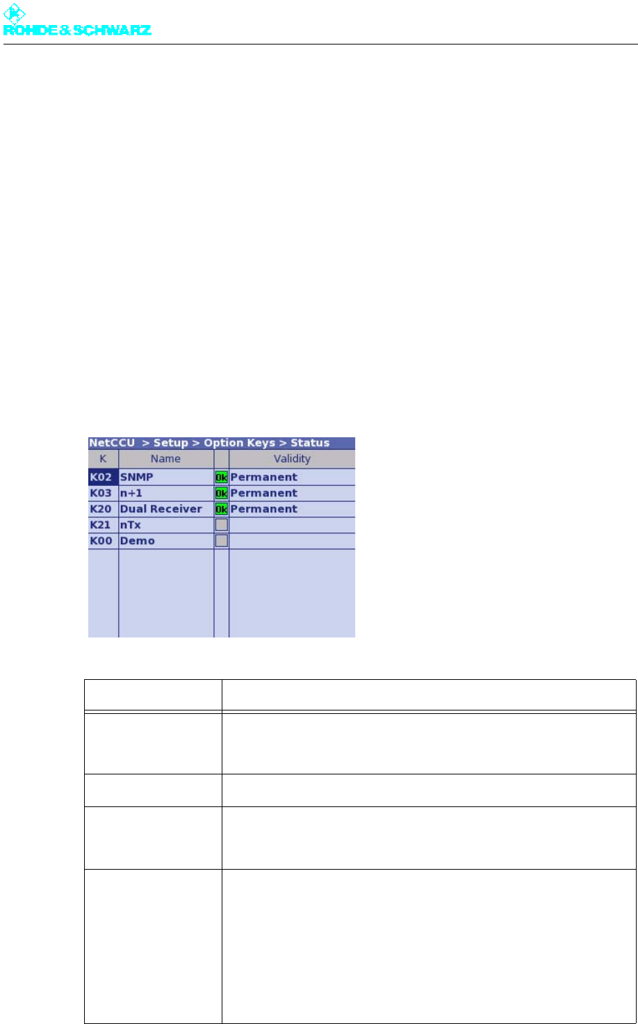
The Setup > Option Keys > Status menu window lists the available software options with
their respective activation status.
List column Explanation
K The K material number and stock number of the device are used to
order an option key to activate a software option from Rohde & Schwarz
sales partners.
Name Name of the software option
— Status of a software option:
– Green (OK): Option has been activated
– Gray: Option has not been activated
Validity Validity period of an installed option key:
– Permanent: Option activated for an unlimited period (standard
license)
– "Expiry date": Option remains activated until the displayed expiry date
(e.g. as a test license)
If the activation mechanism is not supported by the hardware, all soft-
ware options are activated automatically (status = OK). In this case, no
validity period is displayed in the Validity column.
Chapter 5 Operating
2098.0720.72 - 5.44 - E-2
2.6.2.2 Install Menu Window
The Setup > Option Keys > Install menu window is used to install option keys manually.
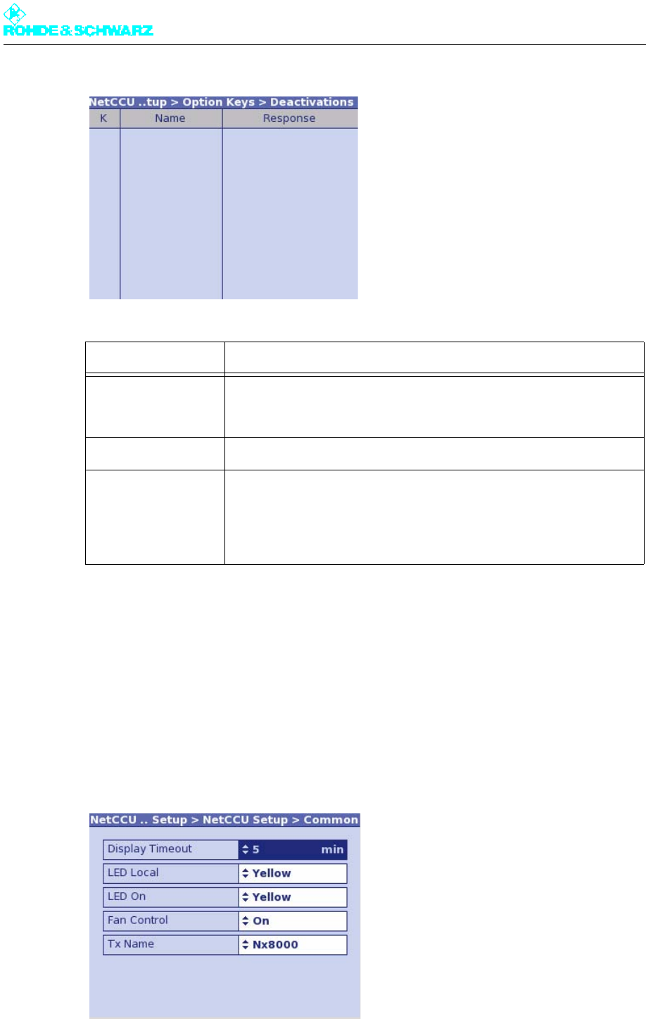
2.6.2.3 Deactivations Menu Window
The Setup > Option Keys > Deactivations menu window lists software options which
were once active, but have been deactivated again using a deactivation key.
Setting item Description
Option Key Used to enter a 30-digit code to activate (or deactivate) a software
option. Entry of the code is completed with Enter or OK.
Display Description
Status – Status = OK: The mechanism used to activate/deactivate software
options is supported by the hardware.
To be able to use a software option, the associated option key must
be installed.
– No key Required: The mechanism used to activate/deactivate soft-
ware options is not supported by the hardware.
All available software options can be used without installing option
keys.
Message Dialog box with the following messages:
– Please enter a key: Prompt to enter a key
– Key OK: Key entered successfully (the display changes back to
"Please enter a key" after a few moments)
– Key deactivated: Deactivation key entered successfully (the display
changes back to "Please enter a key" after a few moments)
– Invalid format: Invalid key entered
Chapter 5 Operating
2098.0720.72 - 5.45 - E-2
2.6.3 NetCCU Setup Menu
You can make basic system settings in the NetCCU Setup menu.
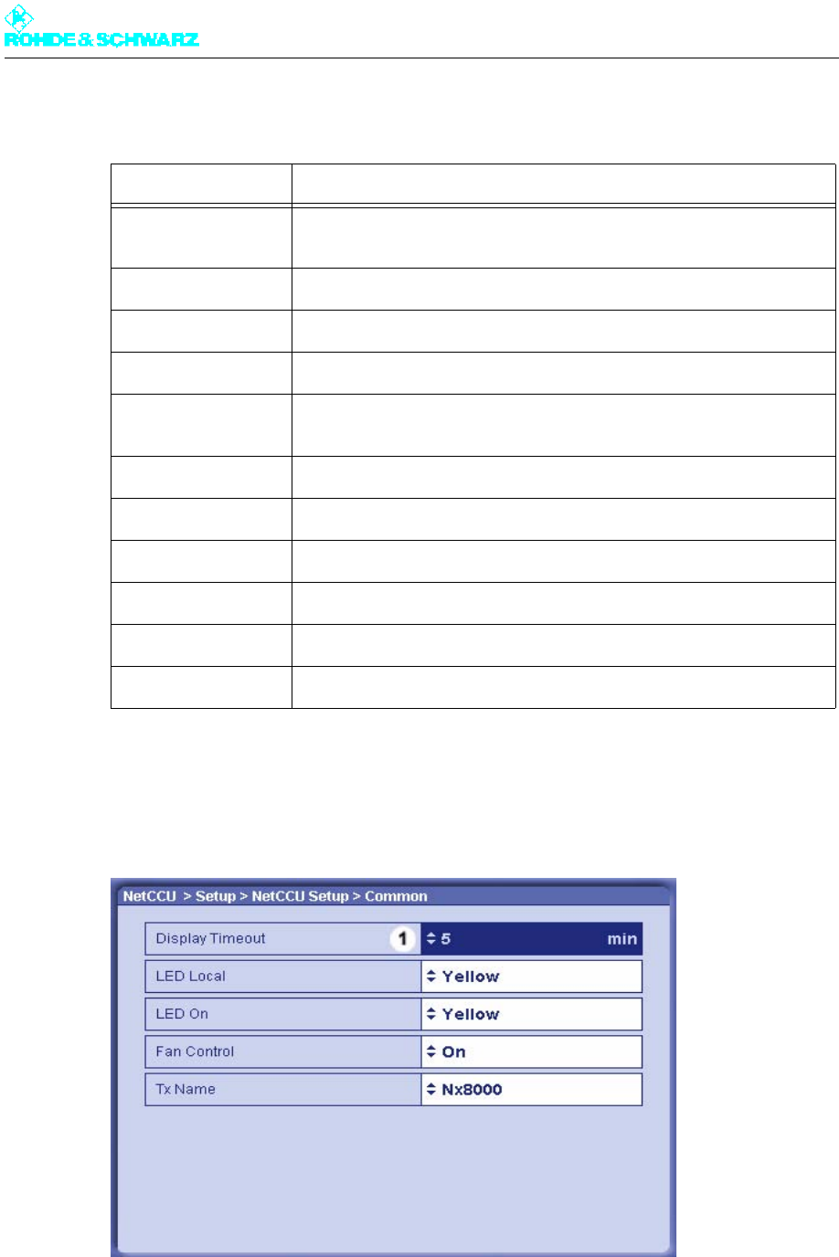
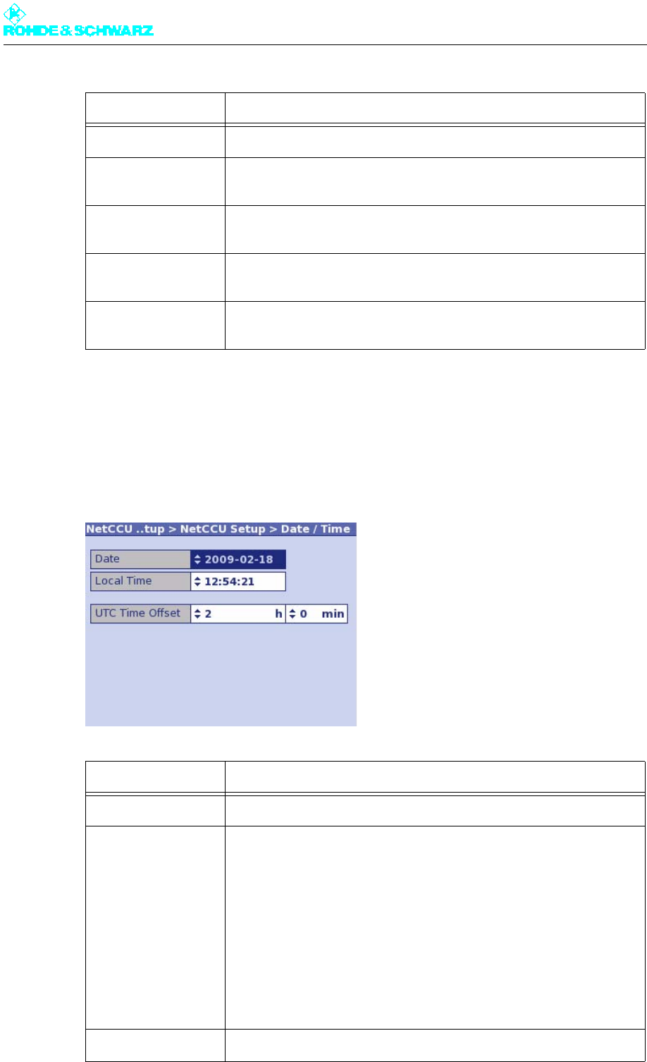
2.6.3.1 Common Menu Window
In the Common menu window, general settings for the system can be made.
Column Explanation
K The K material number and stock number of the device are used for
ordering an option key to activate a software option from Rohde &
Schwarz sales partners.
Name Name of the software option
Response Acknowledgment code as a system response to a deactivation
To prove that a software option has been deactivated, the acknowledg-
ment code must be sent to the Rohde & Schwarz sales partner (e.g. by
e-mail).
Chapter 5 Operating
2098.0720.72 - 5.46 - E-2
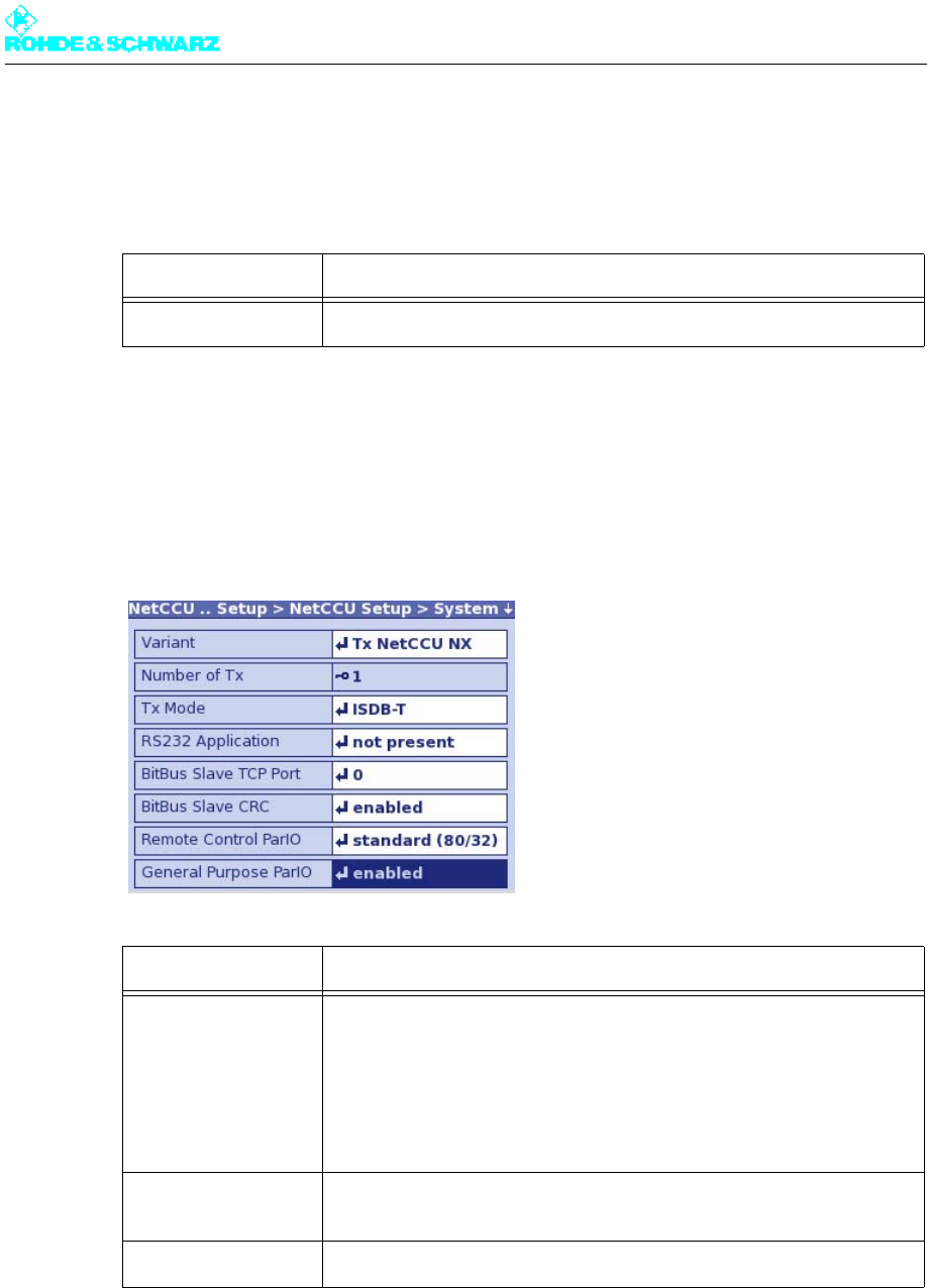
2.6.3.2 Date/Time Menu Window
The date and precise time are required to make correct logbook entries. This information is
supplied by the internal clock of the R&S NetCCU800. If necessary, the time and date can
be corrected in the Date/Time menu window.
Function Explanation
Display Timeout Time in minutes after which the display switches off (standby)
LED Local Color of the Local LED on the front panel of the R&S NetCCU800 (yel-
low, green)
LED On Color of the ON LED on the front panel of the R&S NetCCU800 (yellow,
green)
Fan Control Used to switch the fan monitoring function on and off; the fan monitoring
function must be switched off for instruments without fans.
Tx Name User-definable name for the transmitter; is displayed in the login screen
and in the browser window
Setting item Explanation
Date Used to set the current date
Local Time Used to set the local time
The local time is the time of day or zone time applicable at the station.
Unlike universal time (UTC = universal time coordinated), there is a pos-
itive offset for time zones east of Greenwich or a negative offset for time
zones west of Greenwich.This offset is determined by the time zone and
is always a multiple of a full hour or sometimes of a half hour.
In some countries, the clock is set forward by 1 hour in summer (daylight
saving time). The time offset relative to UTC then changes correspond-
ingly.
UTC Time Offset Used to enter the time offset between local time and UTC
Chapter 5 Operating
2098.0720.72 - 5.47 - E-2
Using NTP
You can change directly to the NTP menu window from the context menu. With NTP, the
local time is determined via NTP and a time set manually under Local Time is overwritten.
2.6.3.3 System Menu Window
You can use the System menu window to make settings which determine how the R&S
NetCCU800 is used. Depending on the selected setting, a different entry screen and differ-
ent menus are displayed after the R&S NetCCU800 is booted.
Function Explanation
Setup NTP Used to change directly to the NTP menu window
Function Explanation
Variant Use of the R&S NetCCU800 as
– NetCCU for low power (Tx NetCCU SV)
– NetCCU for medium/high power (Tx NetCCU NX)
– NSU for a 1+1 system without transmitter connection panels (1+1 w/o
TCB)
– NSU for an N+1 system (n+1 NetCCU)
– NCU for several low-power transmitters (nTx NetCCU)
Number of Tx Number of main transmitters in the transmitter system (only relevant if
the R&S NetCCU800 is used as an NSU/NCU)
TX Mode Used to select the TV/sound broadcasting standard

Chapter 5 Operating
2098.0720.72 - 5.48 - E-2
2.6.3.4 SW Maintenance Menu Window
In the SW Maintenance menu window you can perform software updates for the R&S
NetCCU800 and the connected exciters.
To perform a software update, you must connect the R&S NetCCU800 to a PC which has
the required updates and update software.
Before you call the update software on the PC, you must set the R&S NetCCU800 to Up-
date mode using the Start NetCCU Update context menu. When you call the update soft-
ware on the PC, the software automatically analyzes which updates need to be installed.
The update procedure is started from the PC by means of the update software.
Updates for the R&S NetCCU800 are installed straight away. In a further step, updates for
the exciter(s) must be started from the R&S NetCCU800 via the Start Exciter A/B Update
context menu.
Note The entire update procedure is described in detail in the chapter "Maintenance" in the R&S
NetCCU800 manual.
RS232 Application Used to determine whether the internal RS-232-C interface is used (if a
DVB-T receiver module is installed, the external interface is deactivated
by means of jumpers)
– Not present: RS232 interface is deactivated
– DVB RCV / tcm: RS232 interface is used for DVB receivers (from
other manufacturers)
– DVB RCV / rus: RS232 interface is used for DVB receivers (R&S
instruments)
– BitBus Slave: The R&S NetCCU800 can be controlled via the RS232
interface using the BitBus protocol
– BitBus Master: Another BitBus-compatible instrument can be con-
trolled via the RS232 interface
BitBus Slave TCP
Port
Port address for BitBus slave: For remote control via Ethernet using the
serial interface
BitBus Slave CRC Used to activate/deactivate BitBus slave CRC: Activation for remote
control via Ethernet using the serial interface
Remote Control
ParIO
Used to activate/deactivate the parallel remote interface of the transmit-
ter (connector X9); for selecting a parallel remote interface card with 80/
32 (standard) or 12/9 (mini) outputs/inputs
General Purpose
ParIO
This option makes it possible to use a ParIO board (R&S material num-
ber 5302.3830.02) to connect external devices
Inhibit Status For local mode, the messages from the transmitter are activated/deacti-
vated; with message suppression activated, all traps with the exception
of the local mode trap are suppressed
Ant. Measuring Point Antenna test point present and in use (only for low power with R&S
NetCCU800)
Function Explanation
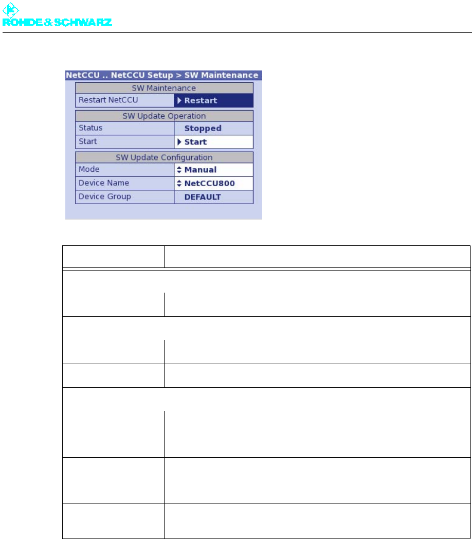
Chapter 5 Operating
2098.0720.72 - 5.49 - E-2
2.6.3.5 SW Backup/Restore Menu Window
You can use the SW Backup/Restore menu to save the software and all R&S NetCCU800
settings as a backup file and to restore the information from this file in full. All information is
backed up to the R&S NetCCU800 flash card.
Note The backup file can also be copied to another storage medium and copied back to the flash
card from there.
Function Explanation
SW Maintenance
Restart NetCCU The R&S NetCCU800 is restarted.
SW Update Operation
Status Displays the progress of the software update installation.
Start Used to start installation of a new software update.
SW Update Configuration
Mode – Manual: Software update is started manually with Start.
– Permanent: Software update is started automatically as soon as an
update is available.
Device Name User-definable name for the R&S NetCCU800; during the software
update, the installation software lists the R&S NetCCU800 under this
name.
Device Group Displays the group in large networks (e.g. department) for which the
software update is being performed.
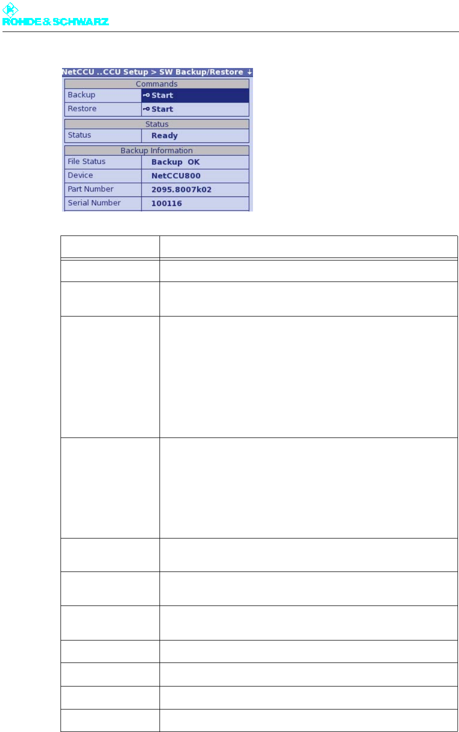
Chapter 5 Operating
2098.0720.72 - 5.50 - E-2
Display Description
Backup For backing up the current state of the software and settings
Restore For restoring the backup (a restore is only possible if the backup con-
cerned is valid; see the Backup Information part of the window)
Status Status of the Backup/Restore procedure
– Ready: The Backup/Restore function is ready
– Check in progress: The backup file concerned is being checked. The
result will be displayed in the Backup Information part of the window
– Restore in progress: A restore procedure is running
– Backup in progress: A backup procedure is running
– Upload in progress: The backup file is being uploaded to the R&S
NetCCU800 from external medium
– Download in progress: The backup file is being transferred to external
medium
File Status Status of the backup file
– Unknown: The status cannot be determined
– Backup OK: The backup is valid
– No backup available: There is no backup in the device
– Invalid backup: The backup is invalid
– Invalid checksum: A checksum error has been detected. The backup
is not consistent
– Invalid device: The backup is not compatible with the NetCCU800
Device R&S name of the device for which software and settings have been
backed up
Part Number R&S part number of the device for which software and settings have
been backed up
Serial Number R&S serial number of the device for which software and settings have
been backed up
Date Date of the backup
Time Local time of the backup
SW Version Version of the software contained in the backup
Tx Name Tx name at the time of the backup
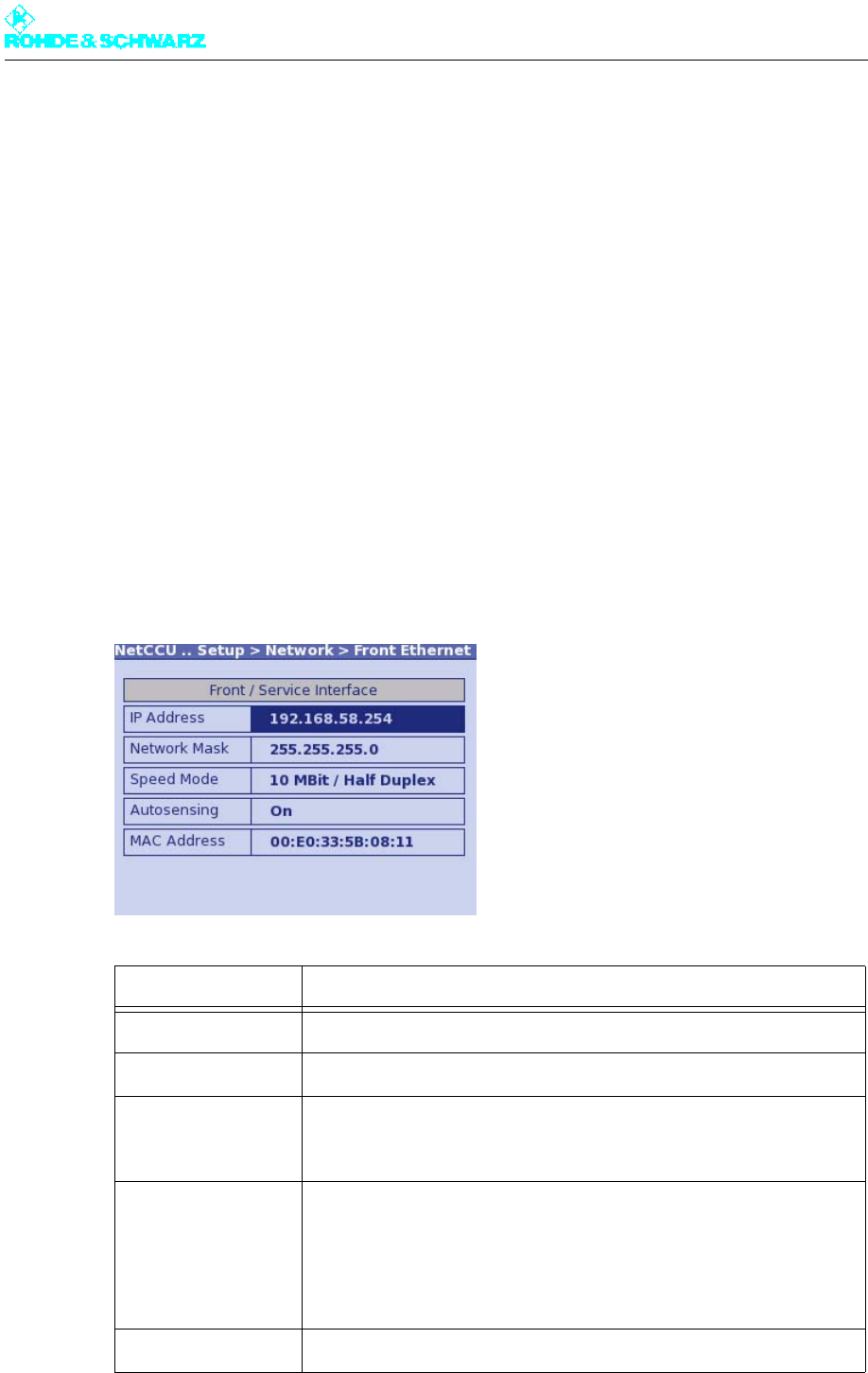
Chapter 5 Operating
2098.0720.72 - 5.51 - E-2
2.6.3.6 Network Submenu
In the menu windows of the Network menu you can make the settings required when con-
necting the R&S NetCCU800 to a PC/laptop or LAN/WAN.
The network settings for the front Ethernet interface are preset. You can configure the set-
tings for the rear interface manually or have them assigned automatically by a DHCP server
in the network.
Menu windows
The Network menu branches to the following menu windows:
–Front Ethernet (connection of a PC/laptop using a cross cable): display of the network
settings for the front interface ETHERNET
–Rear Ethernet (connection to a LAN/WAN): display and configuration of the network
settings for the rear Ethernet interface NETLINK (X5)
2.6.3.7 Network > Front Ethernet Menu Window
Display Explanation
IP Address IP address of the network card
Network Mask Subnet mask of the network card
Speed Mode Speed and duplex
Factory setting: 10 Mbit / half duplex
Autosensing Autonegotiation ON/OFF
Factory setting: On
Autonegotiation = Automatic determination of the settings for the net-
work card
MAC Address Unique ID of the network card
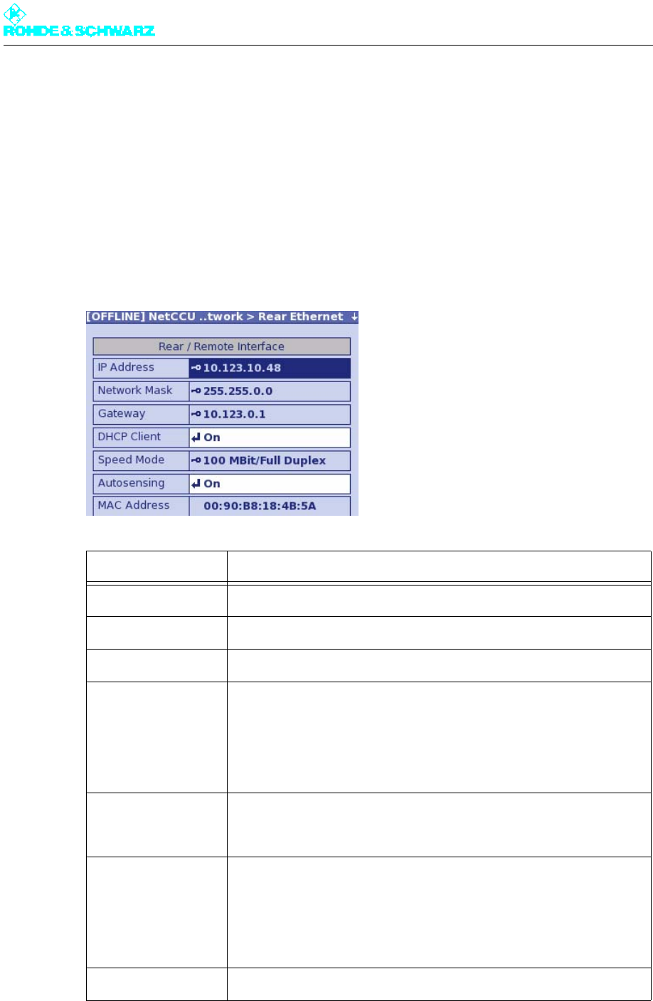
Chapter 5 Operating
2098.0720.72 - 5.52 - E-2
Notes
All settings for the front Ethernet interface are preset. If a PC/laptop is to be connected, the
network interface on the PC/laptop must be configured accordingly:
– IP address (PC): First three segments same as those for IP Address of the R&S
NetCCU800 (see above); a value below 250 must be entered for the last segment
– Subnet mask (PC): Same settings as under Network Mask (see above)
2.6.3.8 Network > Rear Ethernet Menu Window
Setting/display Explanation
IP Address IP address of the network card
Network Mask Subnet mask of the network card
Gateway Gateway address (specified by the network administrator)
DHCP Client Switch used to activate/deactivate the DHCP client:
– On: The network settings for IP address, subnet mask and gateway
are retrieved automatically by a DHCP server
– Off: The network settings for IP address, subnet mask and gateway
must be entered manually (see above)
Speed Mode a)
a) Caution: Only change the settings for Speed Mode and Autosensing in exceptional cases where there are
problems with the network connection.
Speed and duplex
Factory setting: 100 Mbit / full duplex
Autosensing a) Autonegotiation ON/OFF
Factory setting: On
Autonegotiation = Automatic determination of the settings for the net-
work card
MAC Address Unique ID of the network card
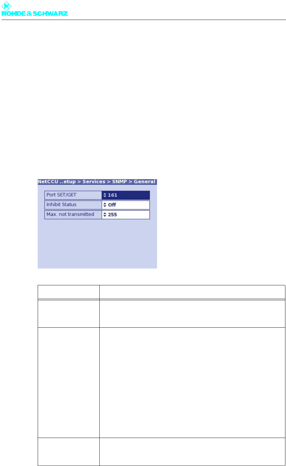
Chapter 5 Operating
2098.0720.72 - 5.53 - E-2
Notes
– Manual settings for remote connection should only be entered in offline mode (context
menu: Edit Offline) and then activated with Submit Changes (context menu).
– The IP address must not be in the same network as the front ETHERNET interface.
– To allow automatic integration in a network (DHCP Client activated), the network must
contain a DHCP server.
2.6.3.9 Services Submenu
In the menu windows of the Services menu, you can make settings for the SNMP, RS232
and NTP communication interfaces.
2.6.3.10 Services > SNMP > General Menu Window
Function Explanation
Port SET/GET UDP port for SNMP SET/GET
Default setting: 161
Inhibit Status Switch for message suppression in Local mode
– Off: Traps (alarm messages) are sent in both operating modes
(Remote and Local)
– On: No traps are sent in Local mode but the alarms are stored; excep-
tion: trap for Local Mode
Default setting: Off
If OIDs are polled with message suppression active, the return value is 0
(undefined). In this operating state, SNMP commands (SET) are not
executed but simply confirmed.
When the Remote mode is reactivated, all stored alarms are sent once.
The polling of OIDs again returns current values.
Max. not transmitted Number of alarms to be stored if message suppression is active
Default setting: 255
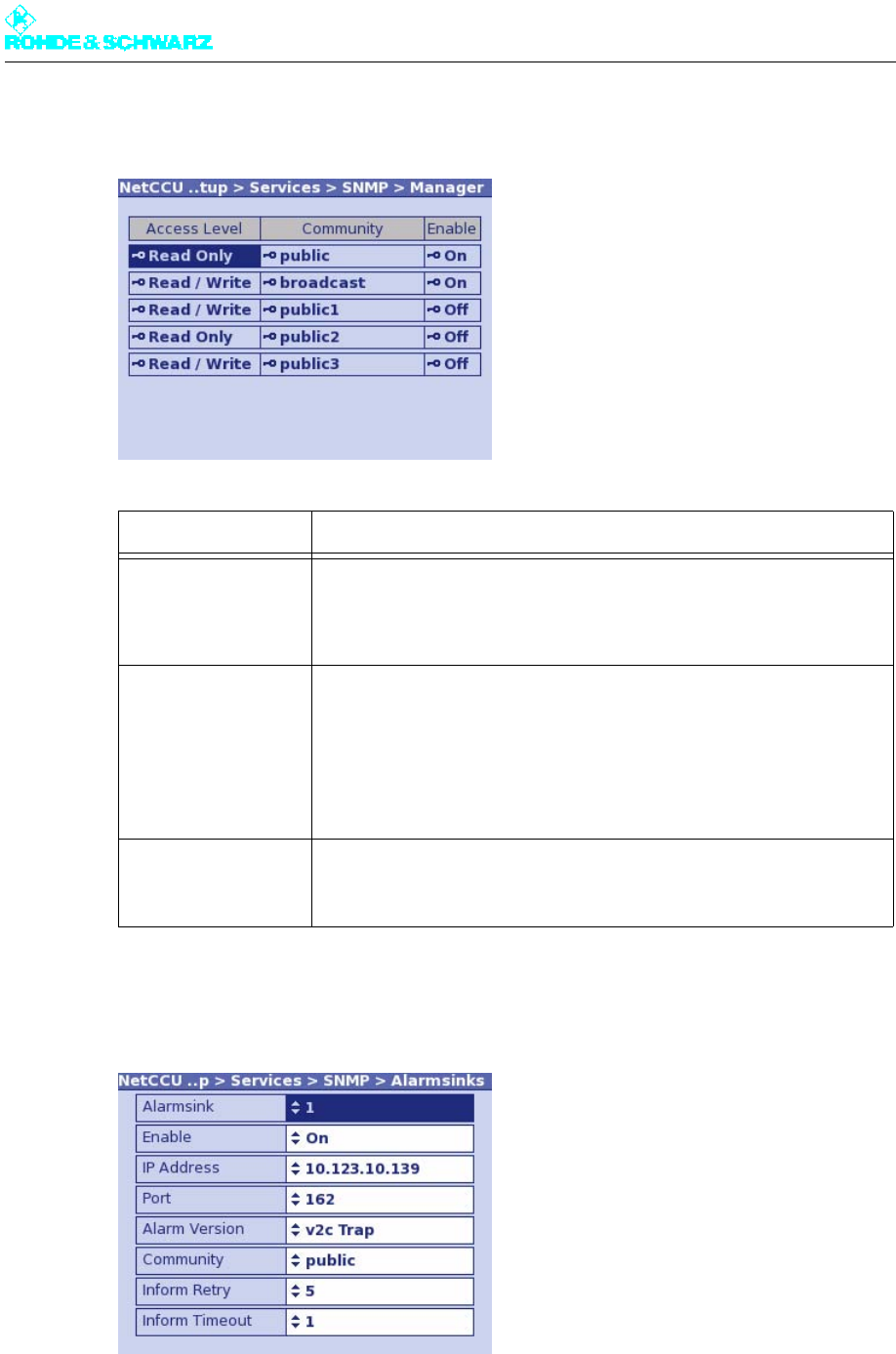
Chapter 5 Operating
2098.0720.72 - 5.54 - E-2
2.6.3.11 Services > SNMP > Manager Menu Window
2.6.3.12 Services > SNMP > Alarmsinks Menu Window
Function Explanation
Access Level [1 … 5] Used to select access authorization for one of five user groups
– Read Only: For GET (only read access to the agent)
– Read / Write: For SET (read and write access to the agent)
Community [1 … 5] Used to set the SNMP community string (a type of password) for a user
group
Default setting: "public" for read only (GET) and "broadcast" for read /
write (SET)
Case-sensitive!
Enable Used to activate (On) or deactivate (Off) a community
The Off setting is used for configuration purposes and for testing.

Chapter 5 Operating
2098.0720.72 - 5.55 - E-2
2.6.3.13 Services > NTP Menu Window
In the NTP (Network Time Protocol) menu window, you can set up synchronization for the
transmitter system. This ensures that the time settings of all system components are syn-
chronized via a common time server.
Function Explanation
Alarmsink Used to select one of 5 alarm sinks for configuration
Enable Used to activate (On) or deactivate (Off) a selected alarm sink
The Off setting is used for configuration purposes and for testing.
IP Address IP address of the alarm sink to which alarms are to be sent
Port UDP port for the SNMP alarms
Default setting: 162
Alarm Version SNMP version in which the alarm is to be sent (v1 Trap, v2c Trap or v2c
Inform)
Traps are sent once only; Informs, however, are repeated several times
until confirmation of the alarm sink is received.
Community Used to select the community (access protection)
The community set here must also be used on the manager side. A dis-
tinction is made between upper-case and lower-case characters.
Communities are configured in the SNMP > Manager menu.
Inform Retry Number of repetitions of an Inform (with v2c Inform only)
If after the final repetition of an Inform no confirmation of the alarm sink
is received , this alarm is no longer sent.
Inform Timeout Time which is to elapse before an inform is sent again (with v2c Inform
only)
Inform Unack’d Number of unconfirmed alarms which can be stored by the agent (with
v2c Inform only)
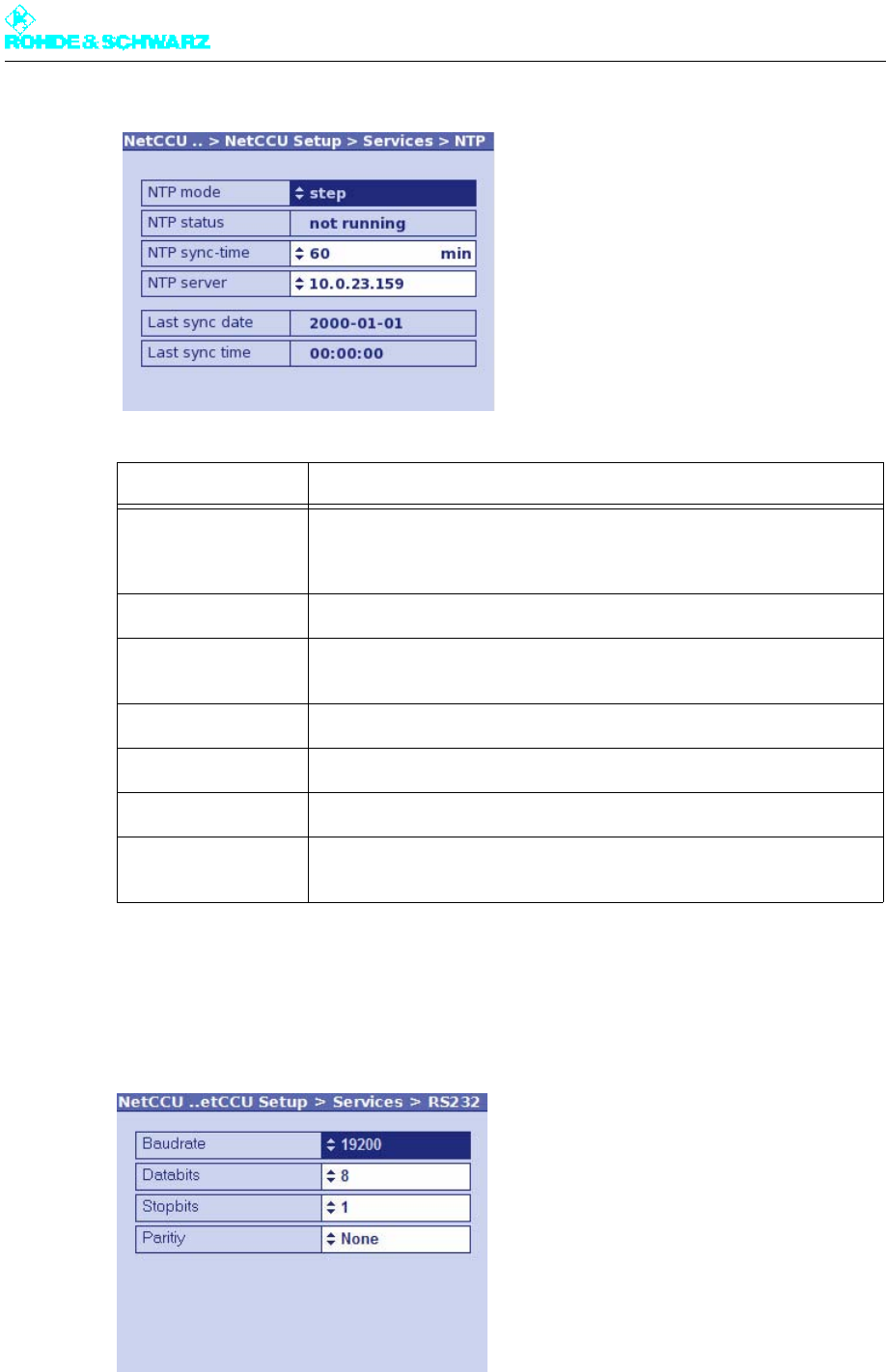
Chapter 5 Operating
2098.0720.72 - 5.56 - E-2
2.6.3.14 Services > RS232 Menu Window
In the RS232 menu window, you can make settings for the RS-232-C interface.
Function Explanation
NTP mode Used to deactivate NTP synchronization (disabled) or to activate NTP
synchronization in step mode; the time is synchronized at the interval
which is set under NTP sync-time (e.g. every 3 minutes)
NTP status Used to set the current status (active/not active)
NTP sync-time Used to set the interval at which the device time (client) is synchronized
with the time of the time server
NTP server IP address or name of the time server
Last sync date Date of the last successfull synchonization
Last sync time Time of the last successfull synchonization
Setup Date/Time
(context menu)
Direct change to the Date/Time menu window
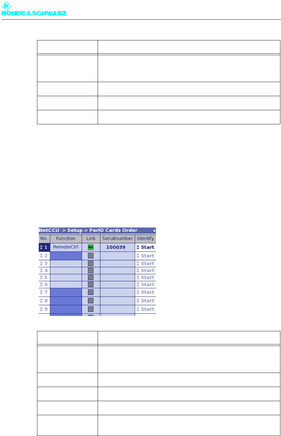
Chapter 5 Operating
2098.0720.72 - 5.57 - E-2
2.6.4 ParIO Cards Order Menu Window
You can use the ParlO Cards Order menu window to identify and assign parallel remote
control interface cards. You need to do this when installing one or more new remote control
interface cards.
Note The window is only displayed if the use of a parallel remote control interface card has been
enabled (see below).
Function Explanation
Baudrate – As required;
If DVB Receiver protocol is selected: setting occurs automatically
If bitbus is used: 19200
Databits Number of data bits of the serial interface (5 to 8)
Stopbits Number of stop bits of the serial interface (1 / 1.5 / 2)
Parity Parity setting
Function Description
No. Position number of the parallel remote control interface card; the num-
ber is directly linked to the remote control interface card displayed at
Serialnumber
Function Function to which the remote control interface card is assigned
Link Displays whether the remote control interface card is enabled
Serialnumber Displays the available remote control interface cards
Identify Identifies a remote control interface card (required when more than one
remote control interface card is installed, or to check for activation)

Chapter 5 Operating
2098.0720.72 - 5.58 - E-2
Assigning and identifying parallel remote control interface cards
Parallel remote control interface cards can be used for the following applications and ad-
ministered and controlled with the NetCCU:
– Remote control of a transmitter (RemoteCtrl)
– Integration and control of transmitters from the NX7000 series or from other manufac-
turers into an n+1 system (SimpleTx)
– Integration and control of third-party equipment (General Purpose ParIO).
– Control of an antenna standby (Antenna Redundancy)
For the respective function (under Function) to be displayed, one or several of the following
settings must be enabled:
For Remote Ctrl:
– NetCCU: NetCCU > Setup > NetCCU Setup > System > Remote Control ParIO >
standard (80/32) or mini (12/9)
–NSU: Switch over Unit > Setup > NSU Setup > Remote Control ParIO > enabled
–NCU: Tx Control Unit > Setup > NCU Setup > Remote Control ParIO > enabled
For Simple Tx:
–NSU: Switch Over Unit > Setup > Tx Setup > Tx A1 to Tx An or Tx B > Variant >
Simple TX ParIO
–NCU: Tx Control Unit > Setup > Tx Setup > Tx A1 to Tx An or Tx B > Variant > Sim-
ple TX ParIO
For General Purpose ParIO:
– NetCCU: NetCCU > Setup > NetCCU Setup > System > General Purpose ParIO >
enabled
–N
SU: Tx Control Unit > Setup > NSU Setup > System > General Purpose ParIO >
enabled
–NCU: Switch Over Unit > Setup > NCU Setup > System > General Purpose ParIO >
enabled
For Antenna Redundancy:
–NSU: Switch Over Unit > Setup > NSU Setup > System > Antenna Redundancy >
Main + Reserve or Upper + Lower
The Function of the respective parallel interface card is displayed in a box highlighted in
light or dark blue. Light-blue highlight for CAN Bus A, dark-blue highlight for CAN Bus B.
When a new parallel remote control interface card is installed, it is detected and displayed
at a random position in the Serial number column. When more than one parallel remote
control interface card is installed, it is usually necessary to identify the real card concerned.
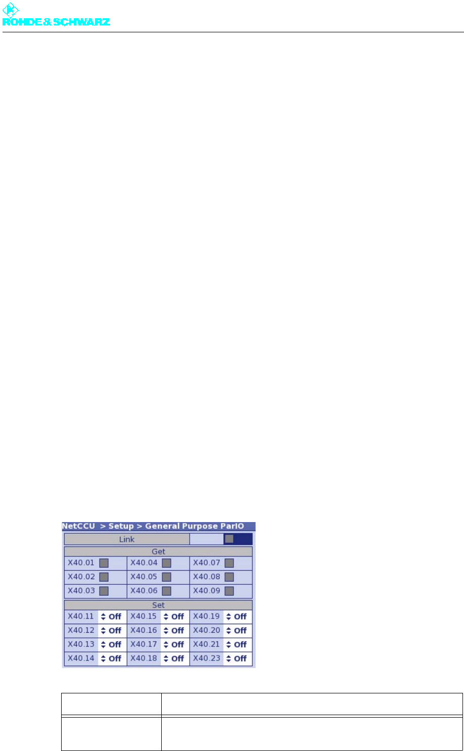
Chapter 5 Operating
2098.0720.72 - 5.59 - E-2
To identify a card displayed in Serial number, highlight IdentifyStart in the column on
the right and confirm with OK.
Click the relay of the card selected, and the card can be identified via this sound.
Note If the card cannot be identified in this way, a helpful alternative is to install the cards one
after another and to identify each card as soon as it is installed, labeling it appropriately.
Each parallel remote control interface card displayed in a random row in the Serial number
column after installation must then be assigned to a function. This is done by means of the
position number (No. column) in the row in which the card is displayed.
1. Double click the position number (No.) of the displayed card.
2. From the editor, select the position number of the row in which the desired function is
displayed (e.g. the No. next to RemoteCtrl) and click OK to confirm.
The selected parallel remote control interface card is assigned to the corresponding
function (the function and card are in the same row).
2.6.5 General Purpose ParIO Menu Window
In the General Purpose ParIO menu window you can control and monitor third-party equip-
ment (e.g. a generator or smoke detector) that is connected via a parallel remote control
interface card.
Note The window is only displayed if the use of a parallel remote control interface card for Gen-
eral Purpose ParIO in the NetCCU > Setup > NetCCU Setup > Remote Control ParIO
menu is enabled.
Depending on the remote control interface cards used, you now have 12 command (set)
and 9 acknowledge (get) or 80 command (set) and 32 acknowledge (get) pins available.
Note For technical reasons, the ratio of the available get and set ports is exactly the reverse com-
pared to remote control interface cards used for controlling transmitters.
Function Explanation
Link Indicator is green when the parallel remote control interface card has
been identified and activated.
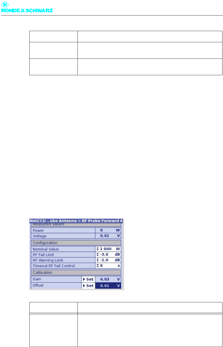
Chapter 5 Operating
2098.0720.72 - 5.60 - E-2
2.7 RF Probe Antenna Menu
You can use the RF Probe Antenna menu to enter and read off the measurement values
for the transmitter system, standby system and output power.
2.7.1 RF Probe Forward Menu Window
In the RF Probe Forward menu window you can define the nominal values for the output
power and determine the lowest level of deviation at which fault messages are to be output.
Two test points are available for measuring the RF power (RF Probe Forward and RF Probe
Reflection). Each test point has two RF rectifiers so that you can measure both the forward
and reflected power. The forward power is always measured using the first test point (RF
Probe Forward).
In the R&S NetCCU800 status screen, the forward power (Forward) is displayed in the left-
hand window and the reflected power (Reflection) in the right-hand window on the basis of
the values entered here.
Get Indicator is green when a port acknowledgment has been sent (e.g. gen-
erator is started)
Set Sends (On) a request to the connected equipment (e.g. start of a gener-
ator)
Function Explanation
Measured Values Measurement display
Power Current forward power
Voltage Currently measured DC voltage of the test point
Function Explanation

Chapter 5 Operating
2098.0720.72 - 5.61 - E-2
2.7.2 RF Probe Reflected Menu Window
In the RF Probe Reflected menu window you can define the nominal values for the output
power and determine the lowest level of deviation at which fault messages are to be output.
Two test points are available for measuring the RF power (RF Probe Forward and RF Probe
Reflection). Each test point has two RF rectifiers so that you can measure both the forward
and reflected power. The reflected power is always measured using the second test point
(RF Probe Reflection).
In the R&S NetCCU800 status screen, the forward power (Forward) is displayed in the left-
hand window and the reflected power (Reflection) in the right-hand window on the basis of
the values entered here.
Configuration Definition and setting of a nominal value for forward power. Setting of
upper and lower thresholds for forward power; warnings and fault mes-
sages are issued if these thresholds are violated.
Nominal Value Used to enter the nominal value, determined if necessary by external
measurement of the forward power
RF Fail Limit Used to select a dB value referenced to the set nominal power for for-
ward power; a fault message is issued if the actual value drops below
the nominal value.
RF Warning Limit Used to select a dB value referenced to the set nominal power for for-
ward power; a warning is issued if the actual value drops below the
nominal value
Timeout RF Fail Con-
trol
Used to select the time that the lower threshold for the forward power
(specified as the RF Fail Limit) must be violated for before a fault mes-
sage is output. For example, if a value of 3 dB has been entered as the
RF Fail Limit and the actual value drops below that level for 8 seconds
(typical setting for Timeout for RF Fail Control), a fault message will be
output.
Calibration Execution of calibration and display of the results.
Gain Internal measurement value of the nominal value
Offset Deviation from the zero value of the power display
Set Gain Used to calibrate the internal measurement system. Set Gain assigns
the currently measured DC voltage to the nominal value for transmitter
power.
Set Offset Used to calibrate the zero point as of which the externally measured
power is displayed. Set Offset calibrates the zero point.
Function Explanation
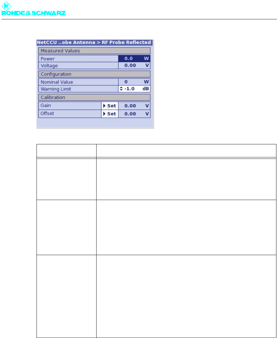
Chapter 5 Operating
2098.0720.72 - 5.62 - E-2
2.8 Device Info Menu
Using the Device Info menu, you can have detailed product information displayed for every
hardware and software component of the R&S NetCCU800.
Function Explanation
Measured Values Measurement display
Power Current reflected power
Voltage Currently measured DC voltage of the test point
Configuration Setting of a warning threshold for the reflected power
Nominal Value Forward power/50 (corresponds to the maximum reflected power)
Warning Limit Used to select a dB value for the warning threshold referenced to the
reflection switch-off threshold which is at a return loss of -17 dB (corre-
sponding to a reflected power/forward power ratio of 1/50)
Calibration Execution of calibration and display of the results
Gain Internal measurement value of the nominal value
Offset Deviation from the zero value of the power display
Set Gain Used to calibrate the internal measurement system. Set Gain stores the
internal measurement value for the entered (measured) nominal value.
Set Offset Used to calibrate the zero point as of which the externally measured
power is displayed. Set Offset calibrates the zero point.
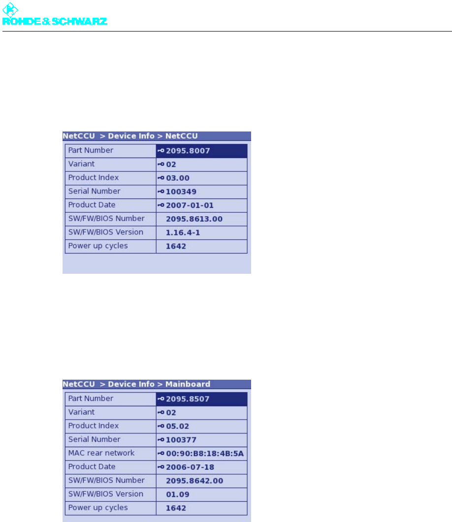
Chapter 5 Operating
2098.0720.72 - 5.63 - E-2
2.8.1 NetCCU Menu Window
The NetCCU menu window displays general information about the hardware and software
of the R&S NetCCU800.
2.8.2 Mainboard Menu Window
The Mainboard menu window displays information about the hardware and software of the
R&S NetCCU800.
2.9 Parameter Set Menu Window
In the Parameter Set menu window, you can create, load and save parameter sets for the
settings of the R&S NetCCU800 and the components it controls. If the operating environ-
ment changes (e.g. change of frequency) you can access complete parameter sets instead
of having to set each individual value. You have eight memory locations available in addition
to the active memory location (for the parameter set loaded).
A parameter set consists of the following parameters:
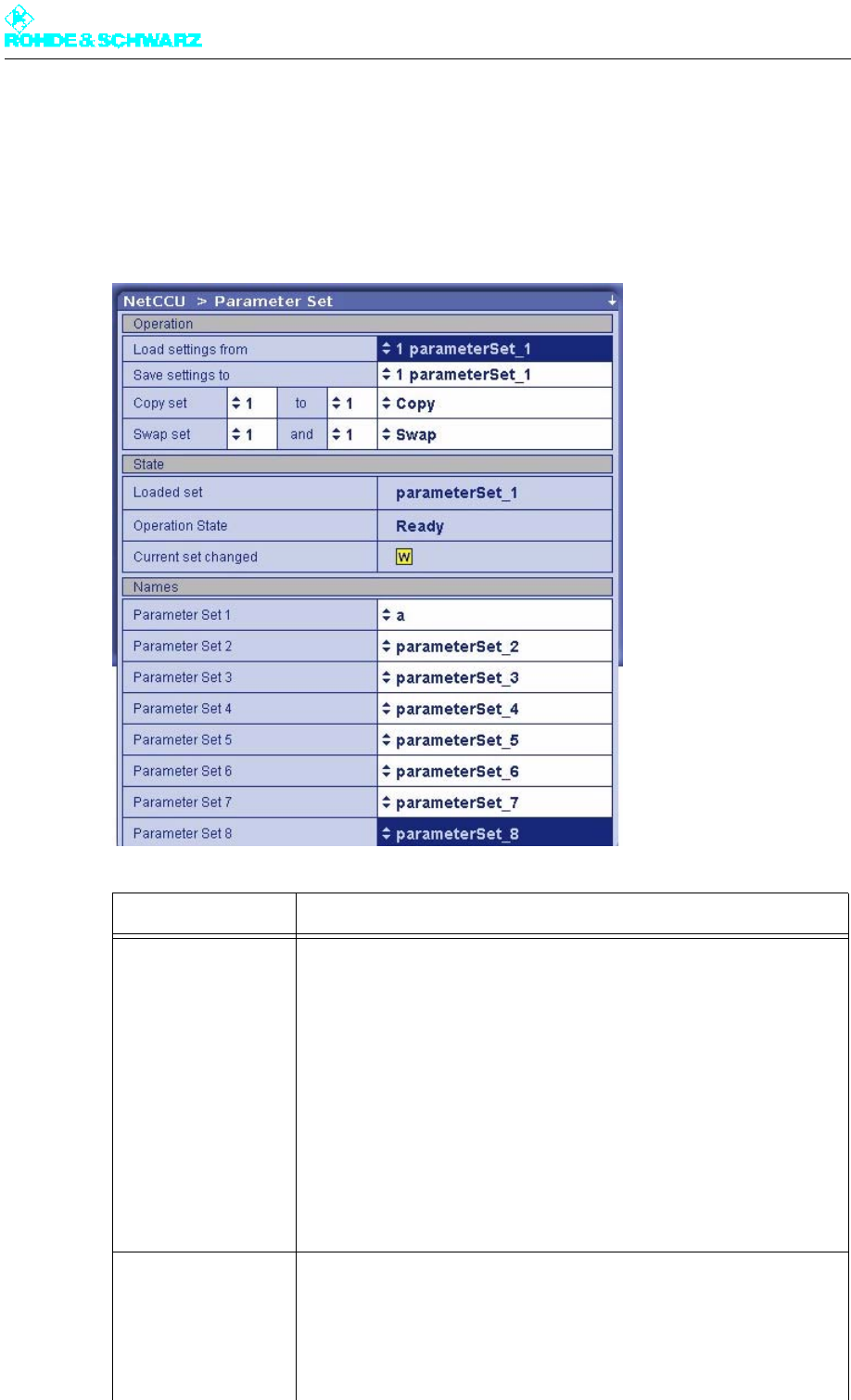
Chapter 5 Operating
2098.0720.72 - 5.64 - E-2
– Settings for the test points (RF Probes), display value at nominal power (Nominal Val-
ue), calibration values (Gain and Offset) for the power displays
– Reference voltage for the forward power
– Virtually all exciter settings, with the exception of instrument-specific parameters (for de-
tailed information, refer to the exciter manual, "Operation" section)
Function Description
Parameter Set
Load settings from For selecting a parameter set as the current parameter set; the currently
loaded parameter set acts as an independent copy of the stored param-
eter set.
Save settings to For saving the currently active settings to the chosen memory location.
Copy set x to y For selecting a parameter set x, the content of which you wish to save to
another memory location y. To start the copying procedure, select Copy
and confirm with OK.
Swap set x and y For selecting two parameter sets x and y, the content of which you wish
to swap. To start the swap procedure, select Swap and confirm with OK.
State
Loaded Set Displays the active (i.e. loaded) parameter set
Operation State Display showing the status of the action that is being carried out (Ready,
Loading, Saving, Copying)

Chapter 5 Operating
2098.0720.72 - 5.65 - E-2
Current Set Changed Yellow: The device settings have been changed and no longer match
the settings of the loaded parameter set.
Names
Parameter Set 1 Name to describe the parameter set (e.g. intended use)
Parameter Set 2 See above
Parameter Set 3 See above
Parameter Set 4 See above
Parameter Set 5 See above
Parameter Set 6 See above
Parameter Set 7 See above
Parameter Set 8 See above
Function Description
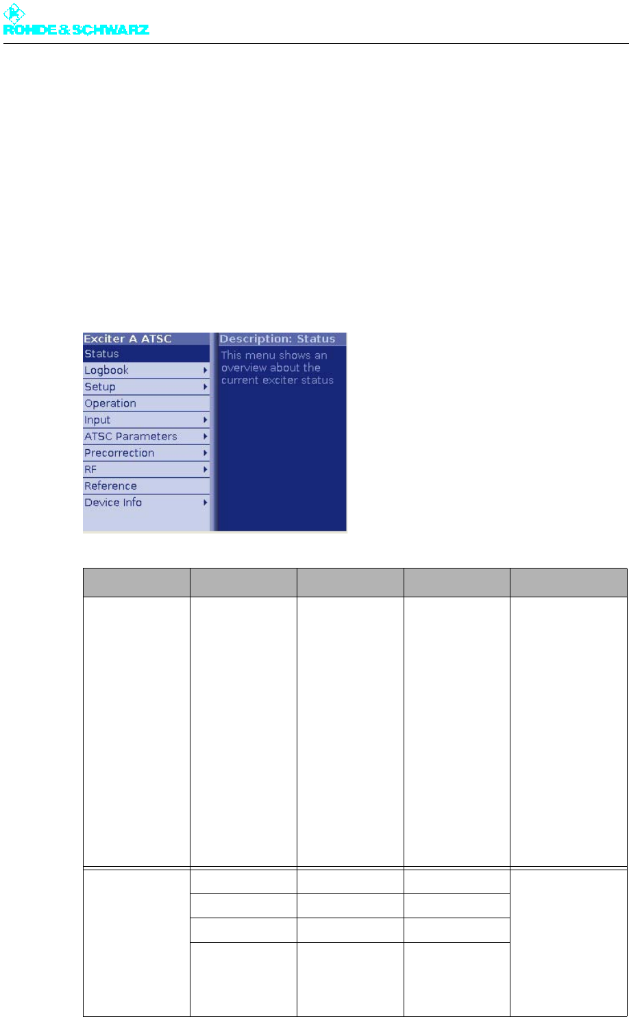
Chapter 5 Operating
2098.0720.72 - 5.66 - E-2
3 Menus of Exciter A/B
You can use the Exciter A/B menus to operate and configure the exciter concerned and to
call up information.
Note The Exciter B menus and menu windows are identical to the Exciter A menus and menu
windows.
3.1 Overview of Menus
Level 1 > Level 2 > Level 3 > Level 4 > Parameter
Status > Displays:
– Sum Fault
–RF
–Exciter
– Loop
– Input
– Input 1 connect
– Input 2 connect
– Reference
– Option Key
–Sum Warning
– Output Terminated
–Self Test
– Temperature
–Fan
– Active Input
– Datarate
–Mute
– Test signal
Logbook > Summary > Logged information:
– No (consecutive
numbering)
– Message
–Time
–Date
– Set or Reset
(for warnings and
error messages
only)
Status >
Warning >
Fault >

Chapter 5 Operating
2098.0720.72 - 5.67 - E-2
Setup > Tx Setup > Setting items:
–Tx Mode
–Tx Name
Setup > Option Keys > Status > Displays:
–K
–Name
– Status: activated/
not activated
– Validity
Setup > Option Keys > Install > Setting items:
– Option Key
Displays:
–Status
– Message
Setup > Option Keys > Deactivation > Displays:
–K
–Name
– Response
Setup > Exciter Setup > Common > Setting items:
– Digital Standard
Displays:
– Amplifier Control
Setup > Exciter Setup > Date / Time > Setting items:
–Date
–Time
Setup > Exciter Setup > Ethernet > Setting items/dis-
plays for the rear Eth-
ernet interface:
– IP Address
– Subnet Mask
– Gateway
Displays for the Front
Ethernet port:
– IP Address
– Subnet Mask
–MAC
Setup > Exciter Setup > BitBus > a) Setting items:
– BitBus Protocol
–TCP Port
– Checksum
Displays:
– Connected
Context menu:
– Reconnect
Setup > Exciter Setup > SNMP > a) General > a) Setting items:
– Port SET/GET
– Inhibit Status
– Max. not transmit-
ted
Setup > Exciter Setup > SNMP > a) Manager > a) Setting items:
– Access Level [1 to
5]
– Community [1 to 5]
– Enable [1 to 5]
Level 1 > Level 2 > Level 3 > Level 4 > Parameter

Chapter 5 Operating
2098.0720.72 - 5.68 - E-2
Setup > Exciter Setup > SNMP > a) Alarmsinks > a) Setting items:
–Alarmsink
– Enable
– IP Address
–Port
– Alarm Version
– Community
Operation > Setting items:
– Program
– Carrier
– Reset on program
off
Context menu:
– Reset Fault
Input > Input Config > Setting items for
Input 1 or Input 2:
– Presel. Mode
Displays for Input 1 or
Input 2:
– Packet Length
– Meas. Data Rate
– Req. Data Rate
– Active Mode
Input > Input Automatic > Setting items:
– Preselect Input
– Autoswitch
–Priority
– Check Time For-
ward
– Check Time Back
– On Input Loss
– Type of Loss of
Input
– Fail Delay Time
Precorrection > Linear > Setting items:
– Linear Correction
– Automatic (ADE) b)
– Max Amplitude
Ripple b)
– Max Group Delay
Ripple b)
Displays:
– Amplitude Ripple b)
–Group Delay Rip-
ple b)
– Input Level b)
– Automatic b)
Precorrection > Nonlinear > Setting items:
– Nonlinear Correc-
tion
– Automatic (ADE) b)
– Threshold Shoul-
ders b)
Displays:
– Shoulder Left b)
– Shoulder Right b)
– Input Level b)
– Automatic b)
Level 1 > Level 2 > Level 3 > Level 4 > Parameter

Chapter 5 Operating
2098.0720.72 - 5.69 - E-2
RF > Synthesizer > Setting items:
– Frequency
– Reference
–OCXO Adjust
RF > Output > Setting items:
– RF Output
– Regulation
– Manual RF Level
– Output Attenuation
–RF Slope
– Modulation Slope
Displays:
– AGC Regulation
RF > IQ Adjust > Setting items:
– Auto I/Q Adjust
(Start/Break)
– I/Q Test Signal
– Bias Coarse [I/Q]
– Bias Fine [I/Q]
– Gain [I/Q]
– Phase
Displays
– Auto I/Q Adjust
(Adjusted/Not
Adjusted/
In Progress)
– LO1 Frequency
RF > Limiter > Setting points for
main limiter:
–State
– Level
Amplifier > c) Setup > c) Setting items:
– Ref Voltage
– Nominal Power
– RF Fail Limit
Displays:
– RF Fail
–Amplifier
– Actual Power
Amplifier > c) Calibration > c) Setting items:
– Ref Voltage
– Nominal Power
– Calibration
Displays:
– Actual Power
– Calibration Power
– Calibration Offset
Reference > Setting items
– Reference
–OCXO Adjust
– Mute on PPS Fail
– Mute on Ref. Fail
– Fail Delay Time
Level 1 > Level 2 > Level 3 > Level 4 > Parameter
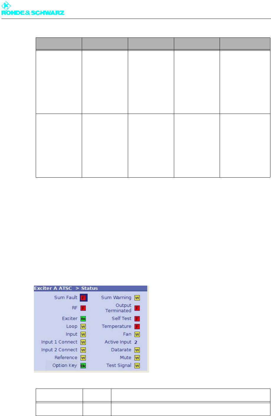
Chapter 5 Operating
2098.0720.72 - 5.70 - E-2
3.2 Status Menu
The Status menu summarizes the current status of the exciter. Color coding (green, yellow
and red) is used to indicate status information, warnings and error messages. In addition,
some basic settings are shown.
Device Info > Exciter > Displays:
– Part Number
– Model
– Product index
– Serial Number
– Product Date
– Software Number
– Software Version
– Operating hours
– Power up cycles
Device Info > Boards > Mainboard > Displays:
– Part Number
– Model
– Product index
– Serial Number
– Product Date
– BIOS version
(mainboard only)
– Operating hours
– Power up cycles
Input Interface >
RF Board >
Synth 1 > d)
Synth 2 > d)
Synth 3 > e)
a) The menu window is only displayed in the Single Low Power mode.
b) The parameter displayed depends on the instrument model (variant) and/or ADE option.
c) The menu window is only displayed in the low-power operating modes of the exciter.
d) The menu window is displayed only for instrument models (variants) 60 and 61.
e) The menu window is displayed only for instrument model 61 (with ADE option).
Display/LED Color Description
Sum Fault Red Sum-fault signal: One or more errors occurred
Level 1 > Level 2 > Level 3 > Level 4 > Parameter

Chapter 5 Operating
2098.0720.72 - 5.71 - E-2
RF Green The RF level at the exciter output is OK
Red There is no RF level at the exciter output even though the RF
output is enabled
- OFF - There is no RF level at the exciter output since the RF output is
not enabled ("manually" disabled)
Exciter Green RF output of the exciter is enabled
There are several options for enabling the RF output:
– using the RF Output setting item in the RF menu
– on the R&S NetCCU800 via the ON key
– on the exciter via the ON key (if a R&S NetCCU800 is not
present or is inactive)
Loop Yellow RF interlock loop not closed
Green RF interlock loop closed
Input Green Valid transport stream present on the active input
Yellow Invalid transport stream on the active input (connected with the
setting Type of Loss of Input = Warning, see the section "Input >
Input Automatic")
Red Invalid transport stream on the active input (connected with the
setting Type of Loss of Input = Fault, see the section "Input >
Input Automatic")
Input 1 connect Green Input signal present at input TS 1 IN
- OFF - No input signal on input TS 1 IN
Input 2 connect Green Input signal present at input TS 2 IN
- OFF - No input signal on input TS 2 IN
Reference Green External reference frequency present and OK
Yellow External reference frequency not OK
Red External reference frequency is not OK and the fail delay time set
in the Reference menu has expired
- OFF - External reference frequency not present, but not actually
needed
Option Key Green All options required for the current transmitter operating mode
are installed
Yellow A temporarily installed option will expire shortly
Red An important option for the current transmitter operating mode is
missing
Sum Warning Yellow One or more warnings are active
Display/LED Color Description

Chapter 5 Operating
2098.0720.72 - 5.72 - E-2
3.2.1 Status Displays, Warnings, and Error Messages
When warnings and error messages occur, this usually means that transmission operation
is impaired. Different signal colors are used to distinguish the severity of an impairment or
the "quality" of the defect. The following applies:
Note This type of LED signaling using colors and abbreviations (OK, W, F, etc) is identical for the
complete menu.
Indications with and without memory effect
Status displays (green) and warnings (yellow) always reflect the current status of the excit-
er. On the other hand, error messages (red) remain active even after the reason for the error
has passed or the error has been corrected. If the error has been corrected, you can reset
the error display with the RESET key.
3.3 Logbook Menu
The logbook is used to record changes in state (events) of the exciter.
Output
Terminated
Red The cable-break sensor has reported that the RF output is not
terminated
Self Test Red A hardware fault has occurred in one or more modules of the
exciter; detailed information about the fault is recorded in the log-
book
Temperature Red At least one module is overheating
Fan Yellow A fan has failed; there is a possibility of overheating
Red Both fans have failed; there is an acute risk of overheating
Datarate Yellow Wrong data rate on the active input
Mute Yellow Output signal from signal processing disabled
Test signal Yellow Exciter is set to test mode
Status display green [OK] Transmission is not impaired.
Warning yellow [W] Although the exciter is functional, external influ-
ences may impair transmission or transmission
operation.
Error message red [F] A severe error has occurred so that transmission
operation is generally not possible.
Display/LED Color Description
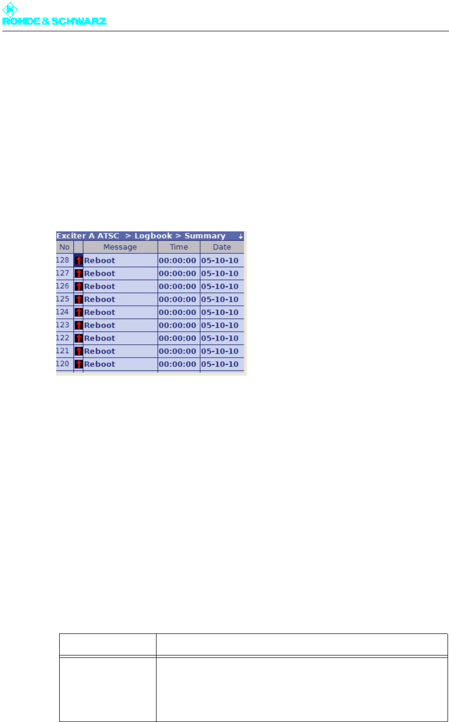
Chapter 5 Operating
2098.0720.72 - 5.73 - E-2
Menu windows
The Logbook menu branches to the following menu windows:
–Summary: Complete logbook with all recorded data
–Status: Partial logbook with recorded status changes
–Warning: Partial logbook with recorded occurrences of warnings
–Fault: Partial logbook with recorded occurrences of error messages
3.3.1 Logbook > Summary/Status/Warning/Fault
The complete logbook and the partial logbooks are uniformly structured. The messages are
numbered sequentially and contain the following information:
– Identification for occurrence or disappearance of an event
– Message: Brief description of the event
– Time: Time of day of the event
– Date: Date of the event
Note Up to 256 entries can be saved in every partial logbook. The most current 128 entries of the
partial logbook will be grouped in the complete logbook.
3.3.2 Logbook Context Menu
Additional context functions are available in the menu windows for the complete logbook
and the partial logbooks:
Function Explanation
Clear logbook Clears all entries in the current logbook; clearing individual logbook
entries is not possible.
When you clear the complete logbook, the partial logbooks are also
cleared. A Reset Fault is triggered at the same time.

Chapter 5 Operating
2098.0720.72 - 5.74 - E-2
3.4 Setup Menu
The menu windows in the SETUP menu are used to make basic settings for transmission
operation, signal processing and operating the exciter.
Menu windows
The Setup menu branches to the following menu windows and menu paths:
–Tx Setup: Used to set the transmitter operating mode
–Option Keys > Status: Status of the available software options
–Option Keys > Install: Used to activate or, if necessary, deactivate software options
–Option Keys > Deactivations: Displays deactivated software options
–Exciter Setup > Common: Used to enter the basic settings for signal processing
–Exciter Setup > Date/Time: Used to enter the current date and time (only required for
"Single Low Power" transmitter operating mode)
–Exciter Setup > Ethernet: Used to configure the Ethernet interface of the exciter (only
possible in the "Single Low Power" transmitter operating mode)
–Exciter Setup > BitBus: Used to activate and configure the BitBus communication via
Ethernet (only possible in the "Single Low Power" transmitter operating mode)
–Exciter Setup > SNMP menu path: Used to configure the SNMP connection (only pos-
sible in the "Single Low Power" transmitter operating mode)
Note Only the menu windows relevant to medium-power and high-power transmitters (i.e. Tx
Setup, Exciter Setup > Common and Option Keys > ...) are described below.
3.4.1 Setup > Tx Setup
The Tx Setup menu window is used to set the exciter software to the appropriate transmit-
ter operating mode.
Restore logbook Restores the cleared entries in the current logbook.
When you restore the complete logbook, the partial logbooks are also
restored.
Function Explanation

Chapter 5 Operating
2098.0720.72 - 5.75 - E-2
3.4.1.1 Setting Transmitter Operating Mode
The exciter can be used in either a medium/high-power transmitter or a low-power trans-
mitter.
Setting item Explanation
Tx Mode Used to set the transmitter operating mode
The options are as follows:
– Med./High Power with NetCCU: Operation in a medium-power or
high-power transmitter with an R&S NetCCU800 as the operator sta-
tion and control unit
– Low Power with NetCCU: Operation in a low-power transmitter with
an R&S NetCCU800 as the operator station
– Low Power 1+1: Operation in a 1+1 standby system for low-power
transmitters with an R&S NetCCU800 switchover unit (NSU) as the
higher-level switching unit and operator station
– Low Power N+1: Operation in an N+1 standby system for low-power
transmitters with an R&S NetCCU800 switchover unit (NSU) as the
higher-level switching unit and operator station
– Single Low Power: Operation in a low-power transmitter; operated via
a connected PC and web browser
In order to switch between two transmitter operating modes, the exciter
must be rebooted a). The associated user interface is loaded.
a) To reboot the exciter, disconnect it briefly from the AC power supply or execute the Reboot Tx command in
the Tx Setup context menu.
Tx Name Used to set an address to allow the NSU to identify the low-power trans-
mitter within an N+1 standby system
The options are as follows:
– Tx A1 to Tx A8: Address range for a main transmitter
– Tx B: Address for the standby transmitter
The setting item "Tx Name" is only active in the transmitter operating
mode "Low Power N+1".

Chapter 5 Operating
2098.0720.72 - 5.76 - E-2
In the first case a R&S NetCCU800 assumes control of the power amplifiers connected to
the rack controller. In the case of a low-power transmitter the amplifiers are connected to
the exciter, which also delivers the control signals.
Each version requires slightly different setup options. These can be enabled with the aid of
the Tx Mode parameter. In the case of low power, a further distinction is made between two
single transmitter modes and two standby modes (see table).
On delivery from the factory, the Med./High Power w. NetCCU operating mode is preset
as standard. When a low-power transmitter is brought into use for the first time, its operating
mode must therefore be changed. The settings do not take effect until the exciter has been
rebooted.1
Note Depending on the configuration of the instruments concerned, it may no longer be possible
to operate the exciter after having changed the operating mode via R&S NetCCU800 or
NSU. This problem can be solved as follows:
a) Configure the operating mode appropriately in the R&S NetCCU800/NSU menu or b)
correct incorrect settings via the web interface of the exciter.
3.4.2 Setup > Option Keys Submenu
Certain features of the device are activated using the Option Keys mechanism.
Each available software option can be enabled by installing a valid activation key. If a soft-
ware option is later no longer required, activation can be canceled again by installing a de-
activation key.
Note The deactivation mechanism allows software options which are no longer required to be
"returned" to Rohde & Schwarz.
Option keys are available from your local Rohde & Schwarz sales partners.
Installing option keys
Option keys can be installed in three ways:
– Automatic installation of one or more activation keys using the Software Distributor
The procedure is the same as for performing software updates (see the chapter "Main-
tenance").
– Installation of an option key by means of a web browser
With this method, the option key can be transferred from, for example, a received mail
using the copy/paste function.
– Installation of an option key directly at the display
With this method, a 30-digit code is entered using the keyboard.
The two last methods use the installation menu Setup > Option Keys > Install described
below.
1 To reboot, briefly disconnect the exciter from the AC power supply.
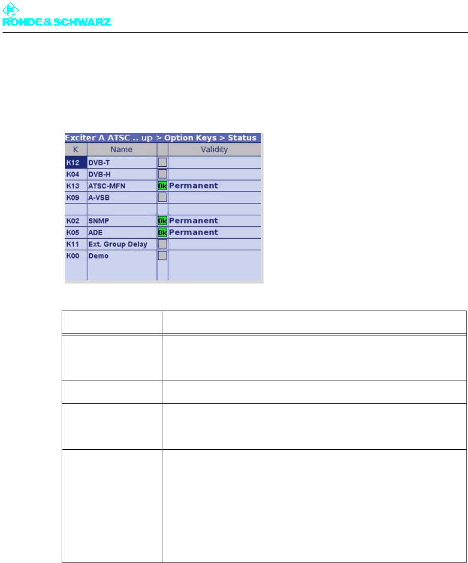
Chapter 5 Operating
2098.0720.72 - 5.77 - E-2
3.4.2.1 Setup > Option Keys > Status
The Option Keys > Status menu window lists the available software options with their re-
spective activation status.
Note There must be (at least) one software option activated for the TV standard in order that the
exciter can generate an RF signal at the output.
3.4.2.2 Setup > Option Keys > Install
The Option Keys > Install menu window is used to install option keys manually.
List column Explanation
K The K material number and stock number of the device are used to
order an option key to activate a software option from Rohde & Schwarz
sales partners.
Name Name of the software option
— Status of a software option:
– Green (OK): Option has been activated
– Gray: Option has not been activated
Validity Validity period of an installed option key:
– Permanent: Option activated for an unlimited period (standard
license)
– "Expiry date": Option remains activated until the displayed expiry date
(e.g. as a test license)
If the activation mechanism is not supported by the hardware, all soft-
ware options are activated automatically (status = OK). In this case, no
validity period is displayed in the Validity column.
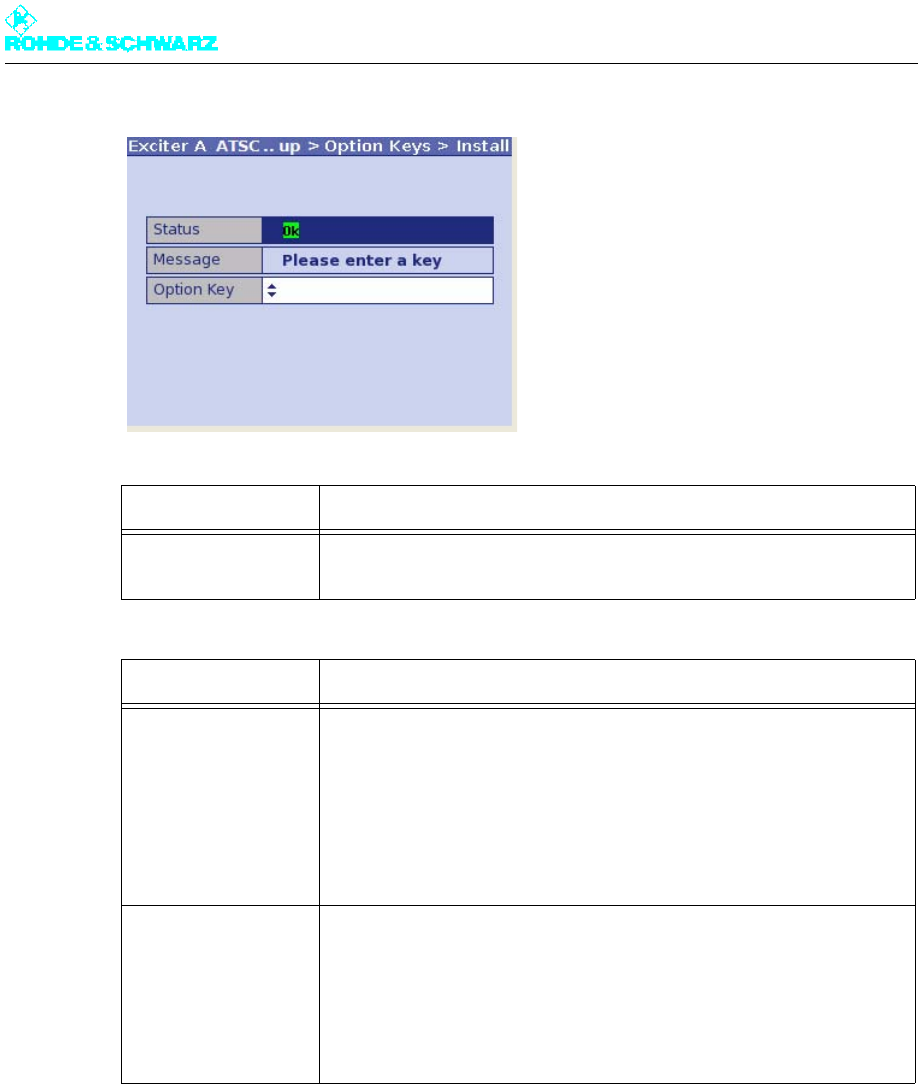
Chapter 5 Operating
2098.0720.72 - 5.78 - E-2
3.4.2.3 Setup > Option Keys > Deactivations
The Option Keys > Deactivations menu window lists software options which were once
active, but have been deactivated again using a deactivation key.
Setting item Description
Option Key Used to enter a 30-digit code to activate (or deactivate) a software
option. Entry of the code is completed with Enter or OK.
Display Description
Status – Status = OK: The mechanism used to activate/deactivate software
options is supported by the hardware.
To be able to use a software option, the associated option key must
be installed.
– No key Required: The mechanism used to activate/deactivate soft-
ware options is not supported by the hardware.
All available software options can be used without installing option
keys.
Message Dialog box with the following messages:
– Please enter a key: Prompt to enter a key
– Key OK: Key entered successfully (the display changes back to
"Please enter a key" after a few moments)
– Key deactivated: Deactivation key entered successfully (the display
changes back to "Please enter a key" after a few moments)
– Invalid format: Invalid key entered
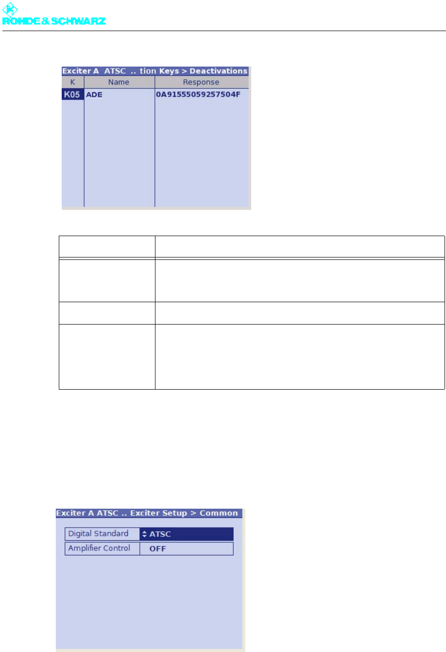
Chapter 5 Operating
2098.0720.72 - 5.79 - E-2
3.4.3 Setup > Exciter Setup > Common
The Exciter Setup > Common menu window is used to enter the default settings for signal
processing.
Column Explanation
K The K material number and stock number of the device are used for
ordering an option key to activate a software option from Rohde &
Schwarz sales partners.
Name Name of the software option
Response Acknowledgment code as a system response to a deactivation
To prove that a software option has been deactivated, the acknowledg-
ment code must be sent to the Rohde & Schwarz sales partner (e.g. by
e-mail).
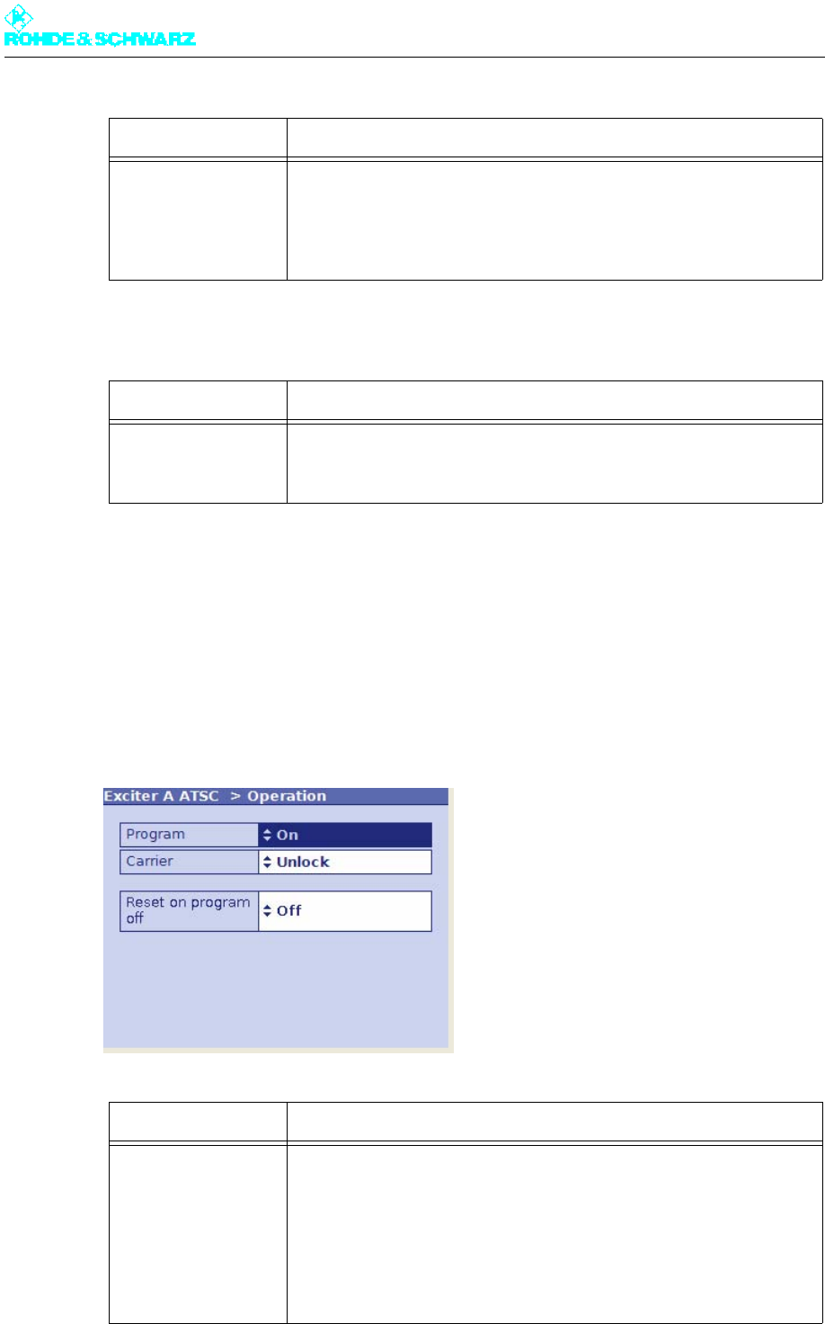
Chapter 5 Operating
2098.0720.72 - 5.80 - E-2
3.5 Operation Menu
The Operation menu window provides functions used to switch the program on and off and
to deactivate an RF carrier loop.
The context menu also provides a function used to reset fault indicators.
Setting item Description
Digital Standard Selection of the digital TV standard: DVB-T, DVB-H or ATSC
To switch over from DVB-T or DVB-H to ATSC you need to reboot a) the
exciter. At the same time signal processing is switched over and the
associated user interface is loaded.
a) To reboot the exciter, disconnect it briefly from the AC power supply or execute the Reboot Tx command in
the Tx Setup context menu.
Display Description
Amplifier Control Status display for amplifier control
In R&S low-power transmitters, the exciter takes over amplifier control.
Setting item Explanation
Program Used to enable (ON) or disable (OFF) the RF output
The function has the same effect as the ON key on the front of the
exciter and, like this key, is only intended for use with the Single Low
Power mode only.
As soon as an R&S NetCCU800 or NSU takes control of the transmitter,
the function has no effect.
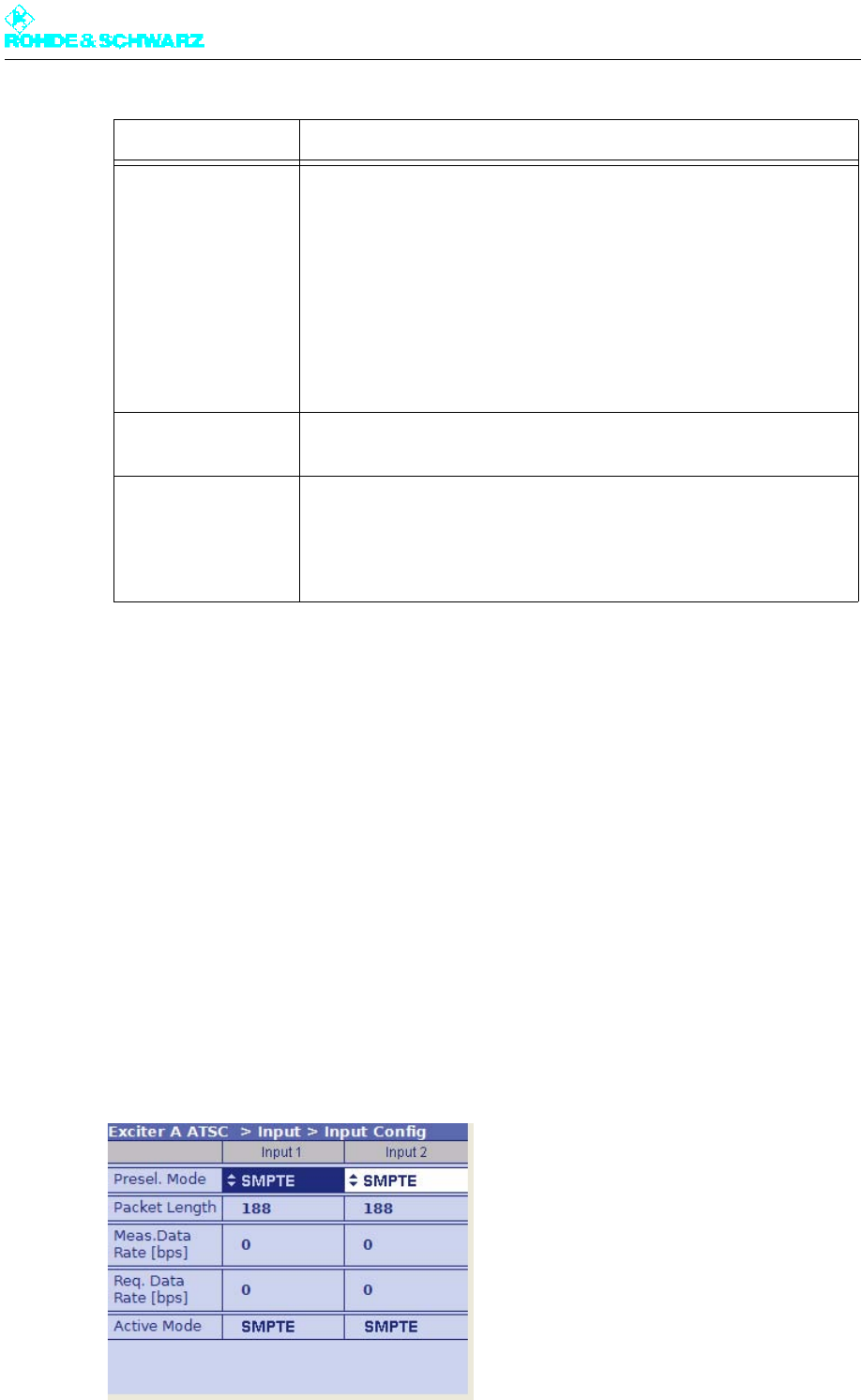
Chapter 5 Operating
2098.0720.72 - 5.81 - E-2
3.6 Input Menu
The menu windows in the INPUT menu can be used to configure up to two input channels.
Menu windows
The Input menu leads to the following menu windows:
–Input Config: Configure input data streams, and display of data format, packet length,
and data rate
–Input Automatic: For preselecting operating input, configuring automatic input switcho-
ver, and setting behavior in the event of input signal failure
3.6.1 Input > Input Config
Carrier Control command for an R&S NetCCU800
With the switch set to Unlock, an RF carrier loop initiated by the R&S
NetCCU800 can be removed in certain service situations.
These service situations include:
– replacement of the exciter
– Failure of the R&S NetCCU800 in standby systems
As soon as an R&S NetCCU800 or NSU takes control of the transmitter,
the function has no effect.
Reset on program off In the ON switch position, a Reset Fault is automatically triggered when
the RF output is locked (Program = OFF).
Reset Fault
(context menu)
Used to reset fault indicators
The function has the same effect as the RESET FAULT key on the front
panel of the exciter and also belongs to the range of functions available
for remote operation via the R&S NetCCU800.
Setting item Explanation
Chapter 5 Operating
2098.0720.72 - 5.82 - E-2
3.6.1.1 Checking Measured Data Rate
By comparing the Meas. Data Rate [bps] and Req. Data Rate [bps], it is possible to check
that the input buffers (FIFOs) are neither overflowing nor underflowing (both cases would
result in transmission interruptions).
Maximum data processing rate
First, all null packets are removed from the transport stream. The associated useful data
rate is measured and displayed under Measured Data Rate. Trouble-free operation is pos-
sible provided that this measurement value remains below the value for Required Data
Rate.
Note After the useful data rate has been measured, stuffing to the required data rate is per-
formed, i.e. the difference between Required Data Rate and Measured Data Rate is com-
pensated by inserting null packets.
Setting item Explanation
Presel. Mode
[Input 1/Input 2]
Sets the data format for the two data streams (main and standby sig-
nals) on inputs TS 1 IN or TS 2 IN.
The options are as follows:
– AUTO: The data format is recognized automatically
– ASI: Manual setting for an ASI transport stream
– SMPTE: Manual setting for an SMPTE transport stream
Display Explanation
Packet Length
[Input 1/Input 2]
Displays the packet length detected at the respective input
Meas.Data Rate [bps]
[Input 1/Input 2]
Displays the data rate measured at the respective input without null
packets
Req. Data Rate [bps]
[Input 1/Input 2]
Display for checking the measured data rate. The maximum data pro-
cessing rate is displayed.
Active Mode Displays the data format detected or set at the respective input:
– ASI: As described
– SMTPE: As described
– AUTO: Auto is selected and there is no data stream
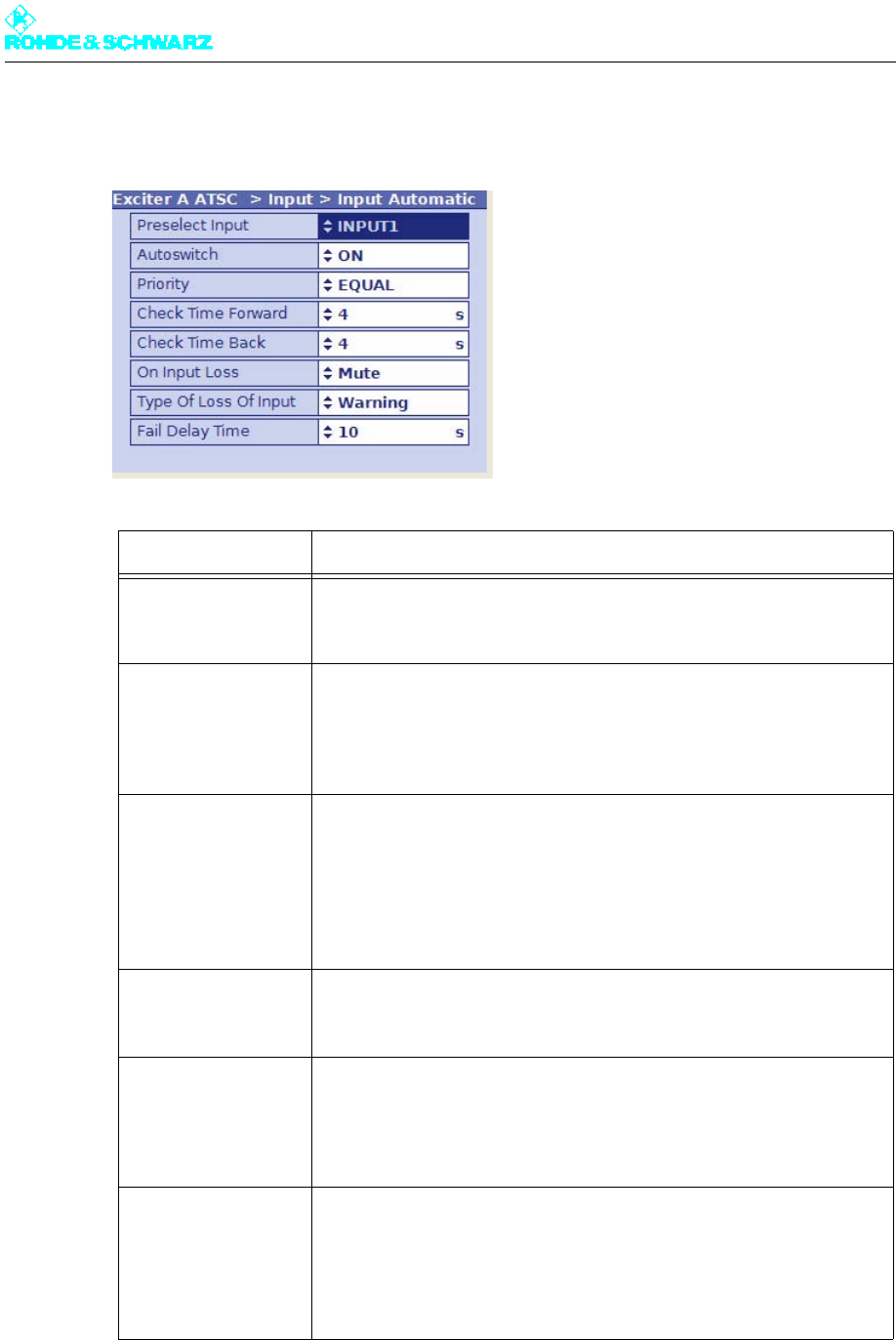
Chapter 5 Operating
2098.0720.72 - 5.83 - E-2
3.6.2 Input > Input Automatic
Setting item Description
Preselect Input Preselection of inputs
– INPUT 1: Operating input is TS 1 IN.
– INPUT 2: Operating input is TS 2 IN.
Autoswitch Activates and deactivates automatic input switchover
In the event of a failure on the active operating input, automatic switcho-
ver to the standby input takes place. The automatic switchover mode is
defined by the following parameter settings.
Priority Selects the priority mode
– EQUAL: The preselected operating input and standby input have the
same priority. Once a switchover has taken place the system does not
normally switch back to the previously faulty operating input.
– PRIO: The preselected operating input is the priority input. Once a
switchover has taken place the system switches back to the prese-
lected operating input as soon as the signal reappears.
Check Time Forward For setting a delay time (0 to 60 s) which must elapse before the
switchover to the standby input takes place in the event of a failure on
the operating input
Check Time Back For setting a delay time (0 to 60 s) which must elapse before switching
back to the preselected operating input after switching over from the
standby input (which is no longer active)
The function has no effect if the priority mode is set to EQUAL.
On Input Loss For setting the behavior in the event of a defective input signal (synchro-
nization error)
– No Mute: The output signal is not suppressed (only effective with
MFN)
– Mute: The output signal is suppressed if the data rate is incorrect (rec-
ommended for SFN)

Chapter 5 Operating
2098.0720.72 - 5.84 - E-2
3.6.2.1 Automatic Input Switchover
The exciter has a circuit for automatic switchover from one input to the other following a sig-
nal failure, provided that a valid signal is present at the second input. Before a failure oc-
curs, the preselected input is active.
The mode of this automatic switchover circuit is defined by the following factors:
– Automatic: ON or OFF (Autoswitch)
– Delay times until switchover (Check Time Forward and Check Time Back)
– Priority mode: Inputs have equal priority or the preselected input has priority (Priority)
Automatic input switchover ON/OFF
If automatic switchover is OFF, the preselected input remains active even if the input signal
fails.
If automatic switchover is ON and there is a failure at the preselected input, switchover to
the associated standby input takes place.
Priority mode PRIO (input priority)
Following a switchover of the preselected input, the automatic system switches back to this
priority input as soon as a signal reappears. Switchover is delayed for the set delay times.
If the signal fails at both the operating input and the standby input, the priority input remains
active.
Priority mode EQUAL (equal input priority)
Following a switchover of the preselected input, the standby input with the same priority re-
mains active until the input signal fails on this input also. The automatic system switches
back to the preselected input, but only if a signal is present on it once again. Switchover is
delayed for the set delay times.
Note Selecting this operating mode keeps to a minimum the number of switchover operations
and in certain cases the number of breaks in transmission (in the case of unsynchronized
input streams).
Type of Loss of Input Selection:
– Warning: If the input signal fails, only a warning will be generated.
– Fault: If the input signal fails, an additional sum fault will be generated
after the time set under Fail Delay Time has elapsed. In the case of
transmitters with exciter standby, switchover to the second exciter
occurs.
Fail Delay Time For setting a delay time which must elapse after an input signal dropout
before a general fault is generated.
Setting item Description
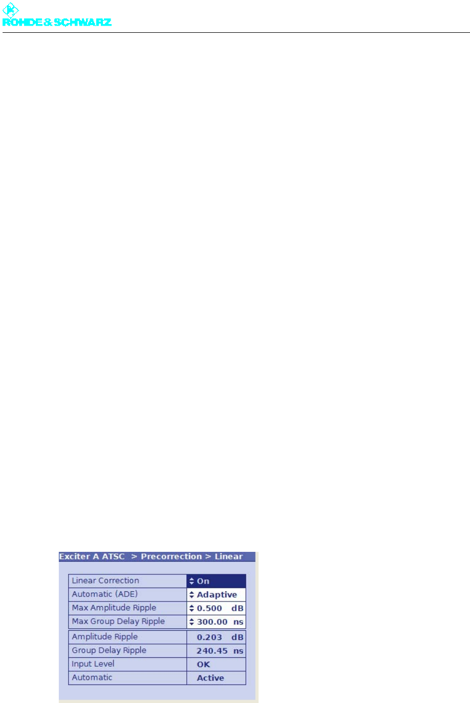
Chapter 5 Operating
2098.0720.72 - 5.85 - E-2
3.6.2.2 Behavior with Defective Input Signal
The behavior in the event of a defective input signal can be influenced by the On Input
Loss switch as follows:
–Mute: The output signal of the exciter is suppressed as soon as synchronization with the
input signal (from the operating input and standby input) is no longer possible.
–No Mute: The output signal of the exciter is not suppressed even though the input signal
is defective. Only null packets are transmitted.
3.7 Precorrection Menu
Using the menu windows in the Precorrection menu, you can activate or deactivate linear
and nonlinear precorrectors individually without having to call up the precorrector GUI (see
the section "Introduction to Precorrector Operation" in the chapter "Operating" of the exciter
manual).
If the software option "ADE" (K05) has been activated, additional functions for the automatic
mode are available. The switch settings (On/Off) correspond to the related settings in the
precorrector GUI.
Menu windows
The Precorrection menu branches to the following menu windows:
– Linear: Switches linear precorrection on or off completely; settings for the ADE option (if
available)
– Nonlinear: Switches nonlinear precorrection on or off completely; settings for the ADE
option (if available)
3.7.1 Precorrection > Linear

Chapter 5 Operating
2098.0720.72 - 5.86 - E-2
Note Further information on how to operate the precorrector can be found in the section "Setting
Linear Precorrection" in the chapter "Operating" of your exciter manual.
Setting item a)
a) Except for the first setting item, the other setting items are only displayed if the exciter is equipped with the
option "automatic precorrection" (ADE).
Explanation
Linear Correction Switches the entire linear precorrection on or off.
Automatic (ADE) Sets the operating mode:
– Manual: linear precorrection is performed manually
– Adaptive: linear precorrection is performed in the automatic mode
Max Amplitude Ripple Sets a limit value for the permitted amplitude ripple in dB; setting range:
0.1 to 2 dB
If the set value is exceeded, a new characteristic is calculated and set.
Max Group Delay
Ripple
Sets a limit value for the permitted group delay ripple in ns; setting
range: 10 to 500 ns
If the set value is exceeded, a new characteristic is calculated and set.
Display a)
a) All display fields are only displayed if the exciter is equipped with the option "automatic precorrection" (ADE).
Description
Amplitude Ripple Displays the residual ripple in the amplitude frequency response
attained by the circuit for automatic switchover
Group Delay Ripple Displays the residual ripple in the group delay attained by the circuit for
automatic switchover
Input Level Status of RF input level:
– OK: RF level on channel RF2 is within operating range
– Failure: channel RF2 is not connected
– Too Low: the RF level in the RF2 channel is too low – increase input
level
– Too High: the RF level in the RF2 channel is too high – decrease input
level
Automatic Status of automatic switchover circuit:
– Active: the automatic switchover circuit and the precorrection are
switched on and wait for the system to be enabled for the next precor-
rection cycle
– Measure: the automatic switchover circuit is in the measurement
cycle and determines the measured values
– Calculate: the automatic switchover circuit calculates the new charac-
teristics based on the measured values and sets them.
– Disabled: the automatic switchover circuit is activated; the precorrec-
tor is still switched off
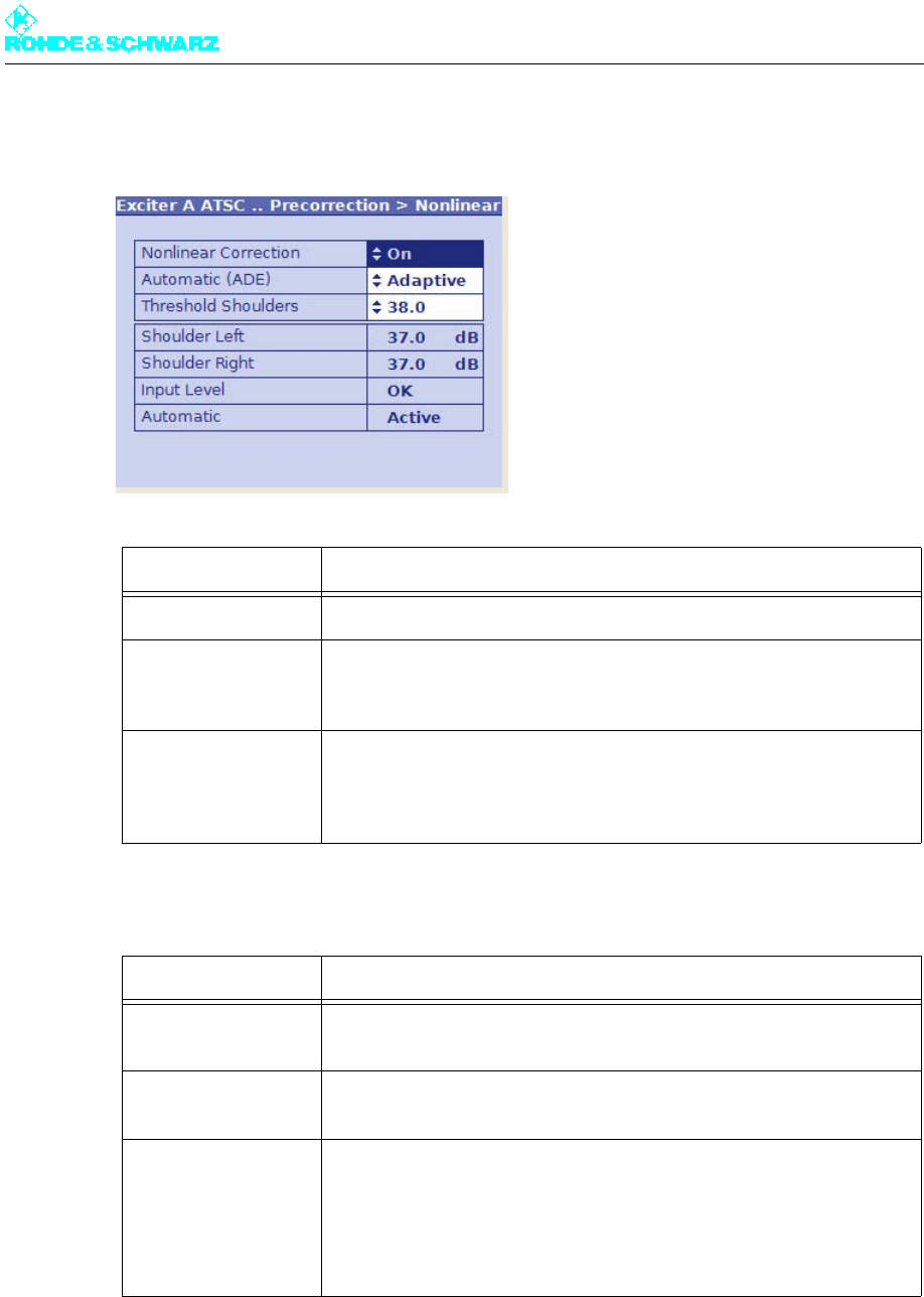
Chapter 5 Operating
2098.0720.72 - 5.87 - E-2
3.7.2 Precorrection > Nonlinear
Setting item a)
a) Except for the first setting item, the other setting items are only displayed if the exciter is equipped with the
option "automatic precorrection" (ADE).
Explanation
Nonlinear Correction Switches the entire nonlinear correction on or off.
Automatic (ADE) Sets the operating mode:
– Manual: nonlinear precorrection is performed manually
– Adaptive: nonlinear precorrection is performed in the automatic mode
Threshold Shoulders Sets a limit value for the permitted shoulder attenuation in dB; setting
range: 20 to 40 dB
If the set value is underrun, a new characteristic is calculated and set.
Display a) Description
Shoulder Left Displays the shoulder attenuation to the left of the signal spectrum
attained by the automatic switchover circuit
Shoulder Right Displays the shoulder attenuation to the right of the signal spectrum
attained by the automatic switchover circuit
Input Level Status of RF input level:
– OK: RF level on channel RF1 is within operating range
– Failure: channel RF1 is not connected
– Too Low: the RF level in channel RF1 is too low – increase input level
– Too High: the RF level in channel RF1 is too high – decrease input
level
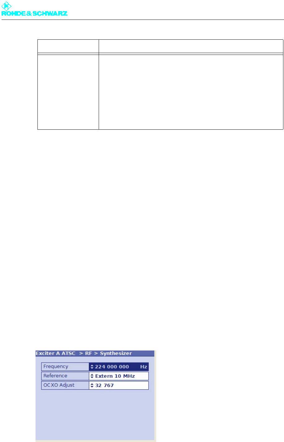
Chapter 5 Operating
2098.0720.72 - 5.88 - E-2
Note Further information on how to operate the precorrector can be found in the section "Setting
Nonlinear Precorrection" in the chapter "Operating" of your exciter manual.
3.8 RF Menu
The menu windows in the RF menu are used to make the settings for frequency generation,
modulation and RF monitoring.
The menu windows
The RF menu leads to the following menu windows:
–Synthesizer: Set pilot frequency and reference frequency source
–Output: Used to enable the RF output, to activate output level control or set the level
manually, or to correct the amplitude frequency response of subsequent components
–IQ Adjust: Used to adjust the modulator
–Limiter: Used to suppress signal peaks in the output spectrum and/or baseband
3.8.1 RF > Synthesizer
Automatic Status of automatic switchover circuit:
– Active: the automatic switchover circuit and the precorrection are
switched on and wait for the system to be enabled for the next precor-
rection cycle
– Measure: the automatic switchover circuit is in the measurement
cycle and determines the measured values
– Calculate: the automatic switchover circuit calculates the new charac-
teristics based on the measured values and sets them.
– Disabled: the automatic switchover circuit is activated; the precorrec-
tor is still switched off
a) All display fields are only displayed if the exciter is equipped with the option "automatic precorrection" (ADE).
Display a) Description

Chapter 5 Operating
2098.0720.72 - 5.89 - E-2
3.8.1.1 Reference Frequency Source
The basis for frequency generation is a 10 MHz oven-controlled crystal oscillator (OCXO).
This OCXO can be operated in different modes:
"Internal" mode
The OCXO runs in uncontrolled mode.
It obtains its control voltage via a D/A converter which can be set using the OCXO adjust
setting item. The OCXO can be adjusted via the 10 MHz MONITORING test output (front
panel of exciter).
"External 5 MHz" and "External 10 MHz" modes
The OCXO runs in controlled mode.
Due to the control, the control voltage generated by the D/A converter is adapted on an on-
going basis so that the 10 MHz frequency of the OCXO is synchronized with the externally
supplied 5 MHz or 10 MHz reference frequency.
"External 1pps" mode
The OCXO runs in controlled mode.
The 10 MHz frequency of the OCXO is synchronized with the external seconds pulse. In
this mode, for example, SFN operation is possible without separate feed of a 10 MHz ref-
erence.
Setting item Explanation
Frequency Setting of the pilot frequency
Reference Selecting the reference source for stabilization of the frequency pro-
cessing (reference frequency source). The following settings are possi-
ble:
– Internal: Operation without external reference frequency source
– External 5 MHz: Operation with external 5 MHz reference
– External 10 MHz: Operation with external 10 MHz reference
– External 1pps: Operation with external time reference (1 pps)
The same setting options can be found in the RF > Reference menu
window.
OCXO Adjust Used to adjust an internal OCXO frequency (for operating mode "Inter-
nal")
The same setting options can be found in the RF > Reference menu
window.
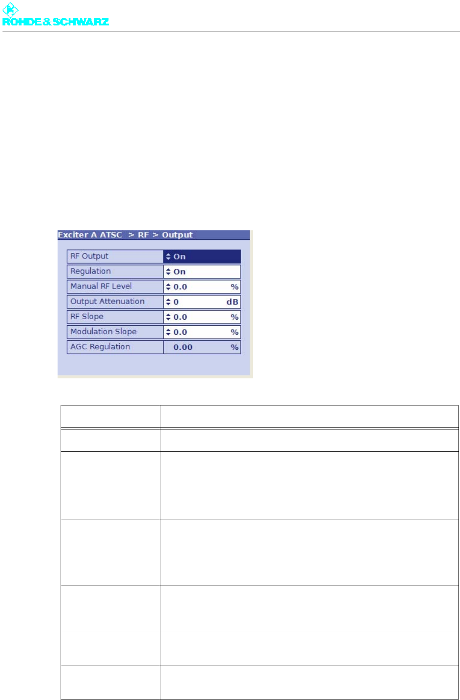
Chapter 5 Operating
2098.0720.72 - 5.90 - E-2
3.8.1.2 Holdover Mode (if reference frequency fails)
As soon as a failure of the external reference frequency is detected, the control voltage for
the OCXO is no longer modified. The result of this is that the RF generation is now based
on the stability of the OCXO.
As soon as the external reference frequency is restored, the control voltage on the OCXO
will be controlled again with the externally supplied reference frequency.
3.8.2 RF > Output
Setting item Description
RF Output Enables (On) or disables (Off) the RF output.
Regulation Activates (On) or deactivates (Off) the output level control. During trans-
mission operation, control must be enabled.
The current status of the related level adjuster is displayed as a percent-
age under RF > RF Monitor > AGC Exciter.
Manual RF Level Manual setting of the output level; the setting has an effect only if output
level control is deactivated.
The current status of the related level adjuster is displayed as a percent-
age under RF > RF Monitor > AGC Exciter.
Output Attenuation For level adaptation purposes, an integrated attenuator with a value of
3 dB, 6 dB or 9 dB can be connected. This has no influence on the level
control.
RF Slope Correction of a slope of the amplitude frequency response in the spec-
trum for equalizing subsequent components (output stage, filter).
Modulation Slope Correction of a curvature of the amplitude frequency response in the
spectrum for equalizing subsequent components (output stage, filter).
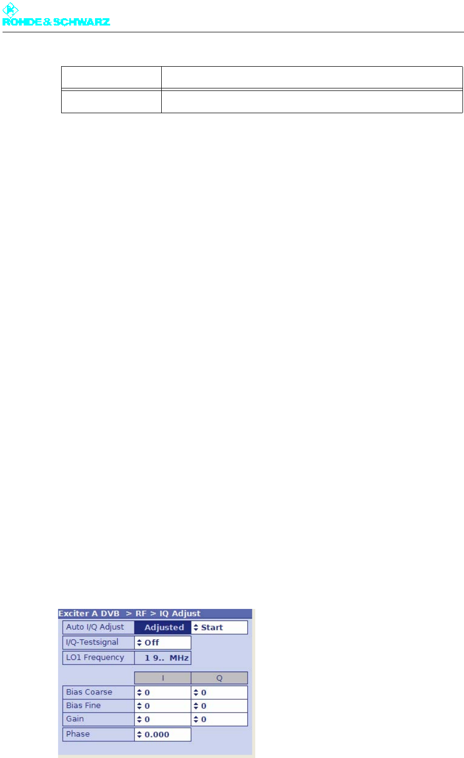
Chapter 5 Operating
2098.0720.72 - 5.91 - E-2
3.8.2.1 Output Level Control
The output power delivered by the exciter is set to the nominal output level of 13 dBm by
means of a controller.
For test purposes, this controller can be deactivated. The output level is then set via the
Manual RF Level control element.
Note If Manual RF Level is set too low, the RF FAIL fault will be generated.
3.8.3 RF > IQ Adjust
When the exciter is delivered, the I/Q modulator is factory-adjusted so that no customer in-
tervention is normally required. If a further I/Q adjustment is needed at a later time, the
menu window RF > IQ Adjust offers the associated setting options.
Note In the section "Maintenance" (exciter manual), you will find a description of how to perform
the I/Q adjustment.
The I/Q adjustment depends on the automatically selected intermediate frequency LO1. Ac-
cordingly, it applies only to the intermediate frequency displayed under LO1 Frequency.
Note The following table shows the relationship between the set vision carrier frequency and in-
termediate frequency LO1:
Display Description
AGC Regulation Displays the level of the output level control
Vision carrier frequency Intermediate frequency
47 MHz fB < 510 MHz LO1 = 2160 MHz
510 MHz fB < 580 MHz LO1 = 1920 MHz
580 MHz fB < 680 MHz LO1 = 2160 MHz
680 MHz fB < 860 MHz LO1 = 1920 MHz

Chapter 5 Operating
2098.0720.72 - 5.92 - E-2
Setting item/Dis-
plays Explanation
Auto I/Q-Adjust Automatic I/Q adjustment
The switch offers the following options:
– Start: starts the automatic I/Q adjustment. The calculation takes
approx. 1 minute. During this time (display Calc), the RF output signal
is suppressed.
– Break: immediately stops the adjustment. The modulator must then
be adjusted again in any case.
Important: Before performing the I/Q adjustment, make sure that the
exciter has been in operation for at least 30 minutes. During adjustment,
transmitter parameters must not be changed.
The values for the actuators Bias Coarse, Bias Fine, Gain and Phase
determined during automatic I/Q adjustment are displayed under the
setting items of the same name for manual adjustment.
The values are valid only for the intermediate frequency displayed under
LO1 Frequency and can, if required, be checked and optimized with a
manual I/Q adjustment (see section "Adjustment of I/Q modulator").
I/Q Test Signal Switches a test signal on or off to manually perform the I/Q adjustment.
Bias Coarse [I/Q] For coarse setting and display of an actuator for suppressing the undes-
ired center carrier; setting range: -1023 to +1023
Bias Fine [I/Q] For fine setting and display of an actuator for suppressing the undesired
center carrier; setting range: -32767 to + 32767
Gain [I/Q] For setting and display of an actuator for suppressing the undesired car-
rier in the sideband; setting range: 0 to 255
Phase For setting and display of an actuator for suppressing the undesired car-
rier in the sideband; setting range: -14 to +14
Display Explanation
Auto I/Q Adjust Status display of automatic I/Q adjustment:
– In Progress: an adjustment has been started; the calculation is cur-
rently being performed.
– Adjusted: After completion of the adjustment, the display changes
from "In Progress" to "Adjusted". This status is valid until a new and
automatic I/Q adjustment is carried out. The "Adjusted" display does
not necessarily mean that the modulator is (currently still) adjusted.
– Not Adjusted: An error has occurred during the last adjustment. The
automatic I/Q adjustment has to be repeated. If the automatic I/Q
adjustment is still not functioning after several attempts, contact tech-
nical support.
LO1 Frequency Display of the intermediate frequency LO1 which is automatically set in
the modulator (1.92 GHz or 2.16 GHz)
The adjustment values of the above actuators are only valid for the dis-
played intermediate frequency.
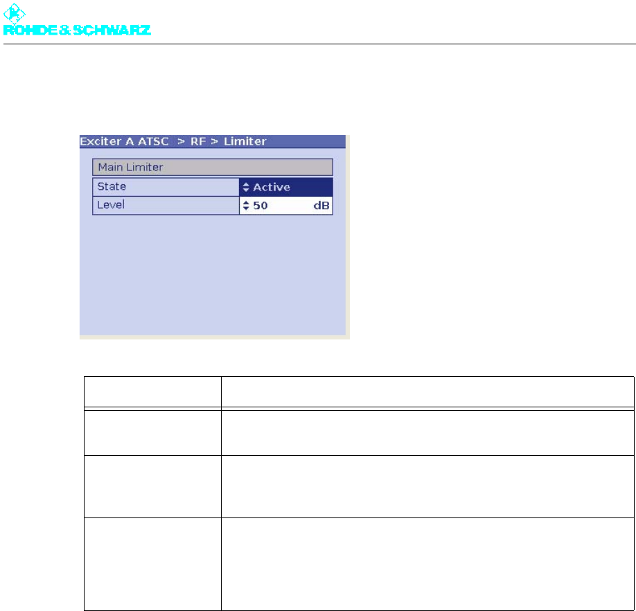
Chapter 5 Operating
2098.0720.72 - 5.93 - E-2
3.8.4 RF > Limiter
3.9 Reference Menu
A reference source for stabilization of the frequency processing (reference frequency
source) can be selected via the Reference menu window.
In addition, the behavior of the exciter can be set for frequency processing if the reference
source fails.
Setting item/display Explanation
Main Limiter The main limiter suppresses signal peaks across the entire output spec-
trum of the exciter.
State Used to activate (Enable) or deactivate (Disable) the Main Limiter
Status display: Active/Off
Level Used to set an operating point for the main limiter
If 100% is set, the limiter is deactivated (like State = Off). If 0% is set, the
useful signal is suppressed completely. This leads to RF Fail. Typical
setting: 50%

Chapter 5 Operating
2098.0720.72 - 5.94 - E-2
Setting item Explanation
Reference Selects the reference frequency source. The following settings are pos-
sible:
– Internal: operation without external reference frequency source
– External 5 MHz: operation with external 5 MHz reference on
– External 10 MHz: Operation with an external 10 MHz reference
– External 1pps: Operation with an external time reference (1 pps)
The same setting options are available in menu window RF > Synthe-
sizer.
OCXO Adjust Setting for adjusting an internal OCXO frequency (for operating mode
"Internal")
The same setting options are available in menu window RF > Synthe-
sizer.
Mute on PPS Fail For setting the behavior in SFN mode in the event of failure of the exter-
nal time reference. The following settings are possible:
– off: The output signal is not suppressed.
– only at startup: the output signal is suppressed at startup until a valid
1 pps signal is recognized; if the 1 pps signal fails after successful
synchronization, the output signal is no longer suppressed.
– after fail delay time: The output signal is suppressed if the 1-pps sig-
nal fails for longer than the period specified at Fail Delay Time
This is the recommended setting for operation in SFN mode.
Mute on Ref. Fail For setting the behavior in SFN and MFN mode in the event of failure of
the external reference frequency source. The following settings are pos-
sible:
– off: The output signal is not suppressed.
– only at startup: the output signal is suppressed at startup until a valid
reference source is detected; if the reference source fails after a suc-
cessful synchronization, the output signal is no longer suppressed
– after fail delay time: The output signal is suppressed if the reference
source fails for longer than the period specified at Fail Delay Time
This is the recommended setting for operation in SFN mode.
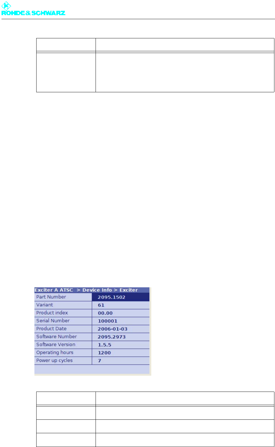
Chapter 5 Operating
2098.0720.72 - 5.95 - E-2
3.10 Device Info Menu
The menu windows under Device Info contain the electronic type plates for the exciter as a
whole as well as for the individual modules or elements in the exciter:
– Exciter (complete device)
– Boards (modules)
– Mainboard
– Input interface
– RF board
– Synth 1 (only with device variants 60 and 61)
– Synth 2 (only with device variants 60 and 61)
– Synth 3 (only with device variant 61)
The structure of the individual type plates is more or less identical. The information which
is displayed is explained below using the exciter type plate as an example:
Device Info > Exciter
Fail Delay Time If a reference source fails, it takes the time given here before the output
signal is suppressed. The setting is only effective if the behavior after fail
delay time is set under Mute on PPS Fail or Mute on Ref. Fail.
Selection: 0 to 24 hours; 0 hours = no delay time
Display Description
Part Number Part number
Variant Device or module variant (model)
Product Index Product modification index
Setting item Explanation
Chapter 5 Operating
2098.0720.72 - 5.96 - E-2
The information saved here is used for troubleshooting purposes. In case servicing is re-
quired, this information allows you to precisely identify the defective component and order
a replacement.
Serial Number Serial number
Product Date Date of production
Software Number Part number for the software
Software Version Version number for the software
Operating hours Number of operating hours
Power up cycles Number of times device has been switched on/off
Display Description

Chapter 5 Operating
2098.0720.72 - 5.97 - E-2
4 Adjustment of I/Q Modulator
Note Before performing the adjustment, make sure that the exciter has been in operation for at
least 30 minutes.
Objective
If quadrature modulation were optimal (theoretically possible), the residual carrier would be
completely suppressed. In actual practice, however, residual carriers arise (e.g. due to
crosstalk). They must be suppressed using suitable correction carriers.
The objective of I/Q adjustment is to suppress the undesired center carrier and undesired
carrier in the sideband with respect to a test carrier by better than 60 dB.
Two methods are available
Two methods are available to perform the I/Q adjustment: setting and testing actuators
manually or via a convenient automatic process.
The automatic method will usually meet the requirements. Yet, it may sometimes be useful
to test the automatically determined values for the actuators and to improve them.
Note How to perform I/Q adjustment is described in the chapter "Maintenance" of your exciter
manual.
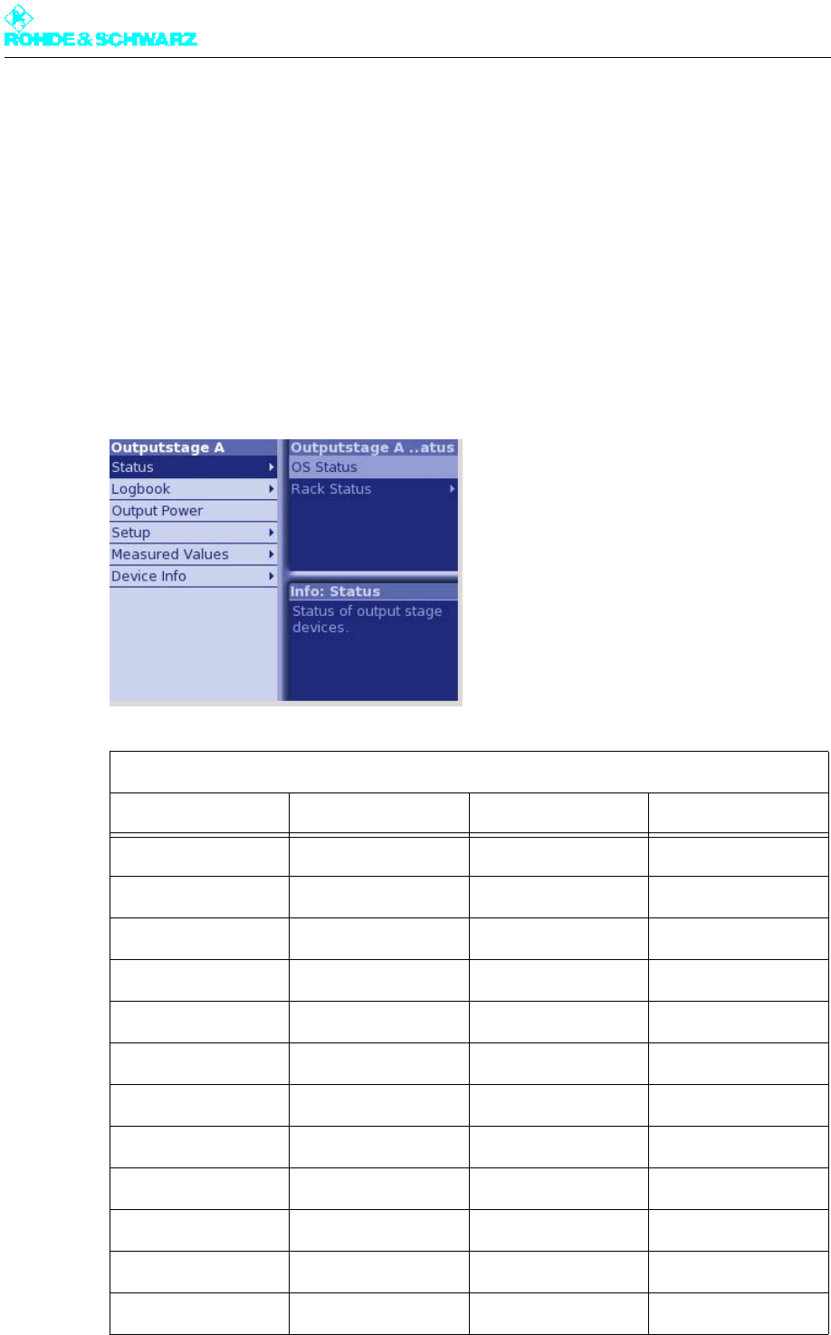
Chapter 5 Operating
2098.0720.72 - 5.98 - E-2
5 Menus of Outputstage A/B
You can use the Outputstage A/B menus to operate and configure the transmitter rack and
the amplifier and to call up information.
Note The Outputstage B menus and menu windows are identical to the Outputstage A menus
and menu windows.
5.1 Overview of Menus
Outputstage A menu structure
Level 1 Level 2 Level 3 Level 4
Status
OS Status
Rack Status
Rack 1
Rack Controller
Amplifier 1 to 4
Logbook
Summary
Status
Warning
Fault

Chapter 5 Operating
2098.0720.72 - 5.99 - E-2
5.2 Status Menu
The Status menu provides an overview of faults, warnings and status messages relating to
the individual output stage components.
Output Power
Setup
OS Setup
Rack Setup
Rack Order
Rack 1
Rack Controller
Amplifier Order
Measured Values
Rack Measured Val-
ues
Rack 1
Rack Controller
Amplifier 1 to 4
Device Info
Rack 1
Rack Controller
Amplifier 1 to 4
Outputstage A menu structure
Level 1 Level 2 Level 3 Level 4
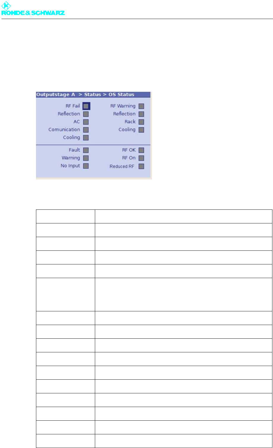
Chapter 5 Operating
2098.0720.72 - 5.100 - E-2
5.2.1 OS Status Menu Window
Outputstage A > Status > OS Status
The OS Status menu window provides an overview of faults, warnings and status messag-
es relating to the output stage components.
The following table explains the meaning of the individual display fields:
Display Explanation
RF Fail Red: Antenna output power is below the set fault threshold
Reflection Red: Antenna reflected power is above the set fault threshold
AC Red: AC supply voltage fault (e.g. phase absent)
Communication Red: Communication to the output stage has been interrupted
Cooling Red: Cooling system fault
Possible causes:
both fans have failed
Fault Red: Output stage sum fault
Warning Yellow: Output stage sum warning
No Input Yellow: No input signal sent to the amplifiers
RF Warning Yellow: Antenna output power is below the set warning threshold
Reflection Yellow: Antenna reflected power is above the set warning threshold
Rack Yellow: There is a fault at at least one transmitter rack
Cooling Yellow: There is a fault in the cooling system
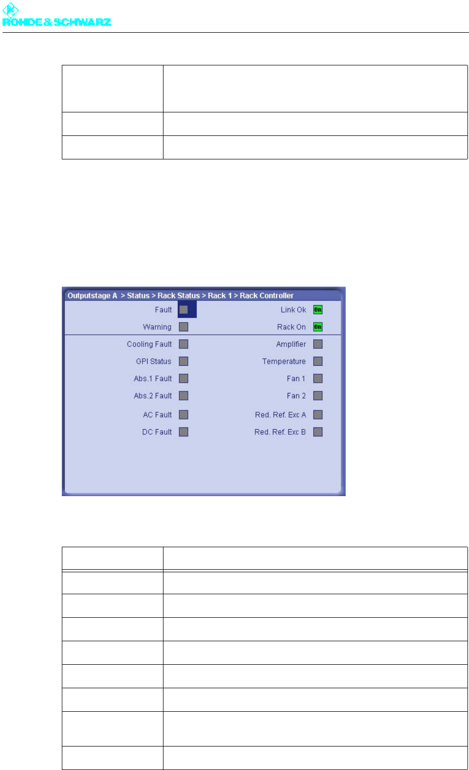
Chapter 5 Operating
2098.0720.72 - 5.101 - E-2
5.2.2 Status/Rack Controller Menu Window
Outputstage A > Status > Rack Status > Rack x > Rack Controller
The Status/Rack Controller menu window provides status information about the rack con-
troller.
The following table explains the meaning of the individual display fields:
RF OK Green: Antenna output power is above the set warning limit
RF On Green: Antenna output power is above the set fault threshold
Reduced RF Yellow: Reduced RF power (only applies to ATV)
Display Explanation
Fault Red: Transmitter rack sum fault
Warning Yellow: Transmitter rack sum warning
Link Ok Green: There is a communication link with the transmitter rack
Rack On Green: ON command at the rack is active
Cooling Fault Red: Cooling system sum fault
GPI Status GPI stands for General Purpose Input. Displays the status of a user-
configurable pin at the rack controller.
Abs. 1 Fault Red: Fault at absorber 1
Display Explanation
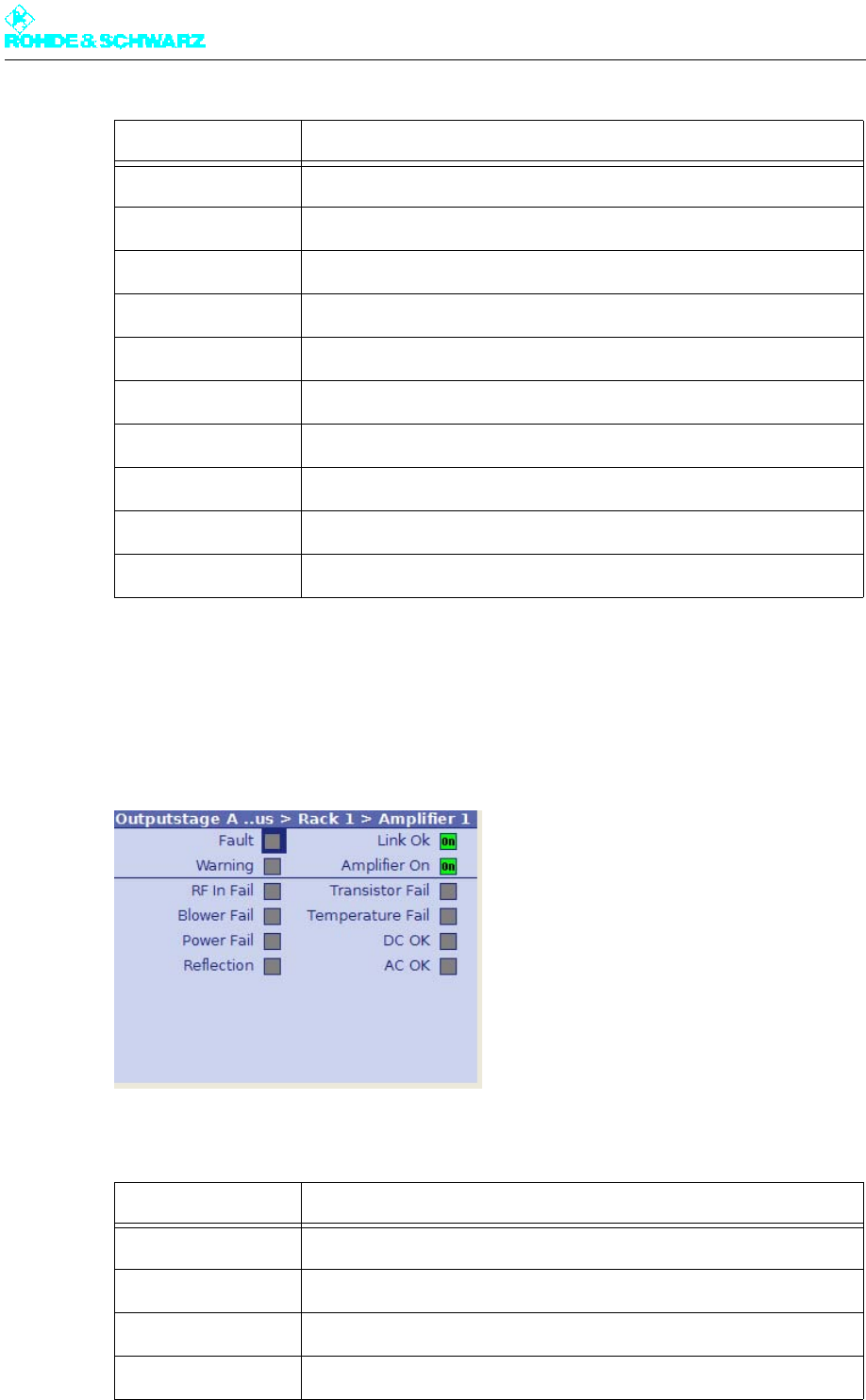
Chapter 5 Operating
2098.0720.72 - 5.102 - E-2
5.2.3 Status/Amplifier x Menu Window
Outputstage A > Status > Rack Status > Rack x > Amplifier
The Status/Amplifier menu window provides status information about the amplifiers.
The following table explains the meaning of the individual display fields:
Abs. 2 Fault Red: Fault at absorber 2
AC Fault Red: AC power supply fault (e.g. phase absent)
DC Fault Red: Fault at auxiliary power supply unit
Amplifier Yellow: Amplifier sum fault (at least one amplifier is indicating a fault)
Temperature Red: Exhaust air temperature is above the set fault threshold
Fan 1 Yellow: Fault at fan 1
Fan 2 Yellow: Fault at fan 2
Red.Ref.Exc.A Only applies to ATV
Red.Ref.Exc.B Only applies to ATV
Display Explanation
Fault Red: Amplifier x sum fault
Warning Yellow: Amplifier x sum warning
Link OK Green: There is a communication link to amplifier x
Amplifier ON Green: Amplifier ON
Display Explanation
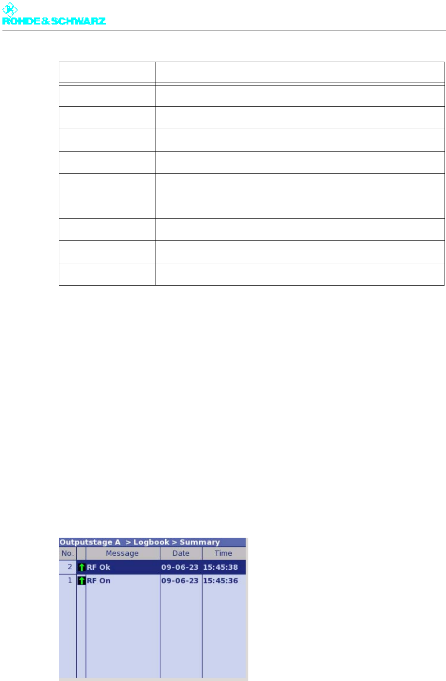
Chapter 5 Operating
2098.0720.72 - 5.103 - E-2
5.3 Logbook Menu
You can use the Logbook menu to query status and error messages about the output
stage.
5.3.1 Logbook Menu Window
Outputstage A > Logbook
You can use the Logbook menu to query status and fault messages about the output stage.
The Logbook menu windows provide an overview of status messages, warning messages
and fault messages about the output stage.
Note You can call up logbook entries in the Summary, Status, Warning and Fault windows.
The following table explains the meaning of the columns:
RF In Fail Yellow: No RF input signal at the amplifier
Blower Fail Not active for this amplifier type
Power Fail Red: Forward power is below the fault threshold
Reflection Red: Reflected power at the amplifier VSWR >1.6
Transistor Fail Red: At least one transistor of the amplifier is faulty
Temperature Fail Red: Heat sink temperature > 85 °C ± 4 K
DC OK Green: Internal DC power supply is OK
AC OK Green: External AC power supply is OK
Display Explanation
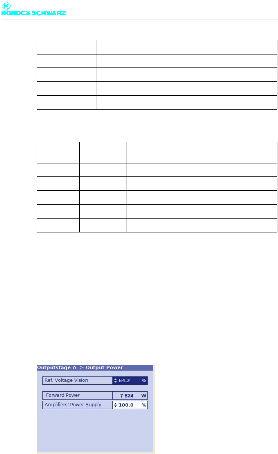
Chapter 5 Operating
2098.0720.72 - 5.104 - E-2
The arrows in the second column have the following meaning:
5.4 Output Power Menu
You may use the Output Power menu to access the Output Power window.
5.4.1 Output Power Menu Window
Outputstage A > Output Power
In the Output Power menu window you can set the output power of the transmitter.
Column Explanation
No Consecutive entry number
Message Message
Time Time at which the message was received
Date Date on which the message was received
Arrow direc-
tion Arrow color Explanation
Up The event has just occurred.
Down The event is no longer current or relevant.
Red Fault
Yellow Warning
Green Status

Chapter 5 Operating
2098.0720.72 - 5.105 - E-2
The following table explains the meaning of the individual settings:
5.5 Setup Menu
You may use the Setup menu to access the OS Setup window.
5.5.1 OS Setup Menu Window
Outputstage A > Setup > OS Setup
In the OS Setup menu window you can make basic settings for the output stage.
Setting/display Explanation
Ref. Voltage Vision Used to set the transmitter output power
Value: 0% to 100%
Forward Power Current reading of the transmitter-internal power display
The displayed value is only valid after the transmitter power has been
entered under the parameter "Nominal Value" and the power display
has been calibrated.
Amplifiers’ Power
Supply
DC supply voltage of the amplifier
Value: 31% to 100%
100% corresponds to a nominal DC supply of 32 V.
31% corresponds to a nominal DC supply of 12 V.
The efficiency can be improved by reducing the DC supply voltage.
Large changes in the DC supply voltage are only permitted if the ampli-
fier is operated below the nominal power.
Caution: Current limiting
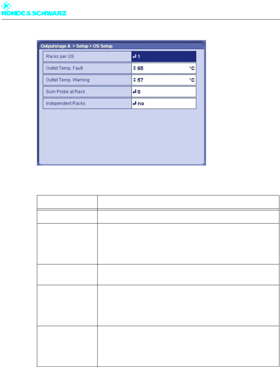
Chapter 5 Operating
2098.0720.72 - 5.106 - E-2
The following table explains the meaning of the individual settings:
5.5.2 Rack Setup > Rack Order Menu Window
Note This menu window is not relevant for single-rack transmitters.
Setting Explanation
Racks per OS Number of racks belonging to the output stage
Outlet Temp. Fault Switch-off threshold with overtemperature
If this threshold is exceeded, the rack controller shuts down the transmit-
ter rack.
Value: 45 °C to 65 °C
Nominal value: 65 °C
Outlet Temp. Warning Warning threshold for overtemperature
A warning is generated if this threshold value is exceeded.
Sum Probe at Rack Used to select the transmitter rack (rack controller) to which the test
points for forward/reflected power of the entire output stage are con-
nected
Only with active and passive output-stage standby
Independent Racks Possibility of dividing the output stage logically into independent racks
– no: All racks of the output stage are controlled together and all act on
the same RF output (default setting).
– yes: The racks of the output stage can have separate RF outputs and
can be controlled individually (e.g. ON/OFF command).
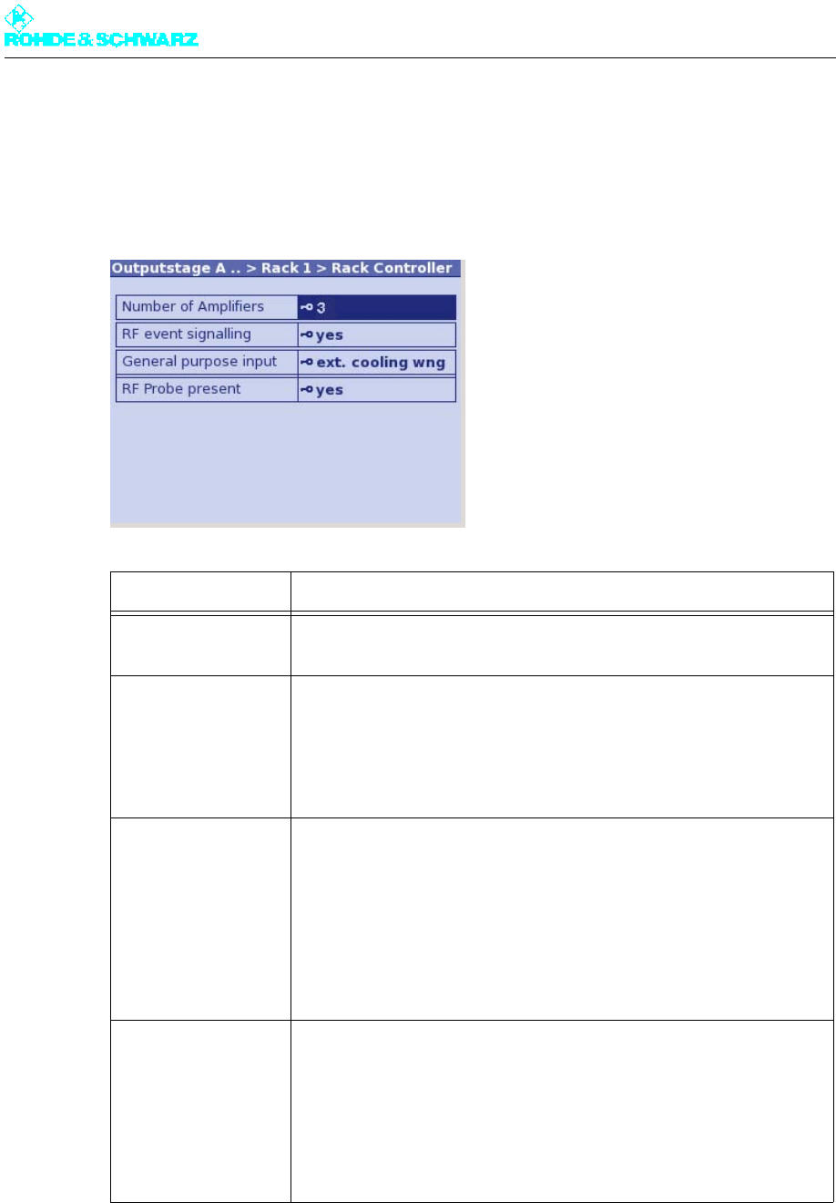
Chapter 5 Operating
2098.0720.72 - 5.107 - E-2
5.5.3 Rack Setup > Rack x > Rack Controller Menu Window
The Rack Controller menu window is used to inform the rack controller, for example, how
many amplifiers are installed in the rack and whether the rack has its own measurement
system.
Setting Explanation
Number of Amplifiers Used to enter the number of amplifiers installed in the rack
Value: 1 to 4
RF event signaling – yes: If the minimum or maximum limits for forward and reflected
power (RF Fail Limit, RF Warning Limit) are violated at the test points
of the rack, warnings or fault messages are output (default setting).
– no: Output of RF warnings and fault messages at the test points of the
rack is suppressed.
General purpose
input
Assignment of a free line on the rack controller for customer-specific
purposes:
– unused: Line is not used.
– door open: Line is reserved for indicating when door contacts are
open.
– ext. cooling wng: Line is reserved for warnings from an external cool-
ing system.
– ext. cooling flt: Line is reserved for fault messages from an external
cooling system.
RFProbe present – yes: A measurement system is connected to the rack controller of the
rack.
Only with active or passive output-stage standby if the measurement
system is connected to this rack.
– no: No measurement system is connected to the rack controller of the
rack.
Correct setting in all other cases.
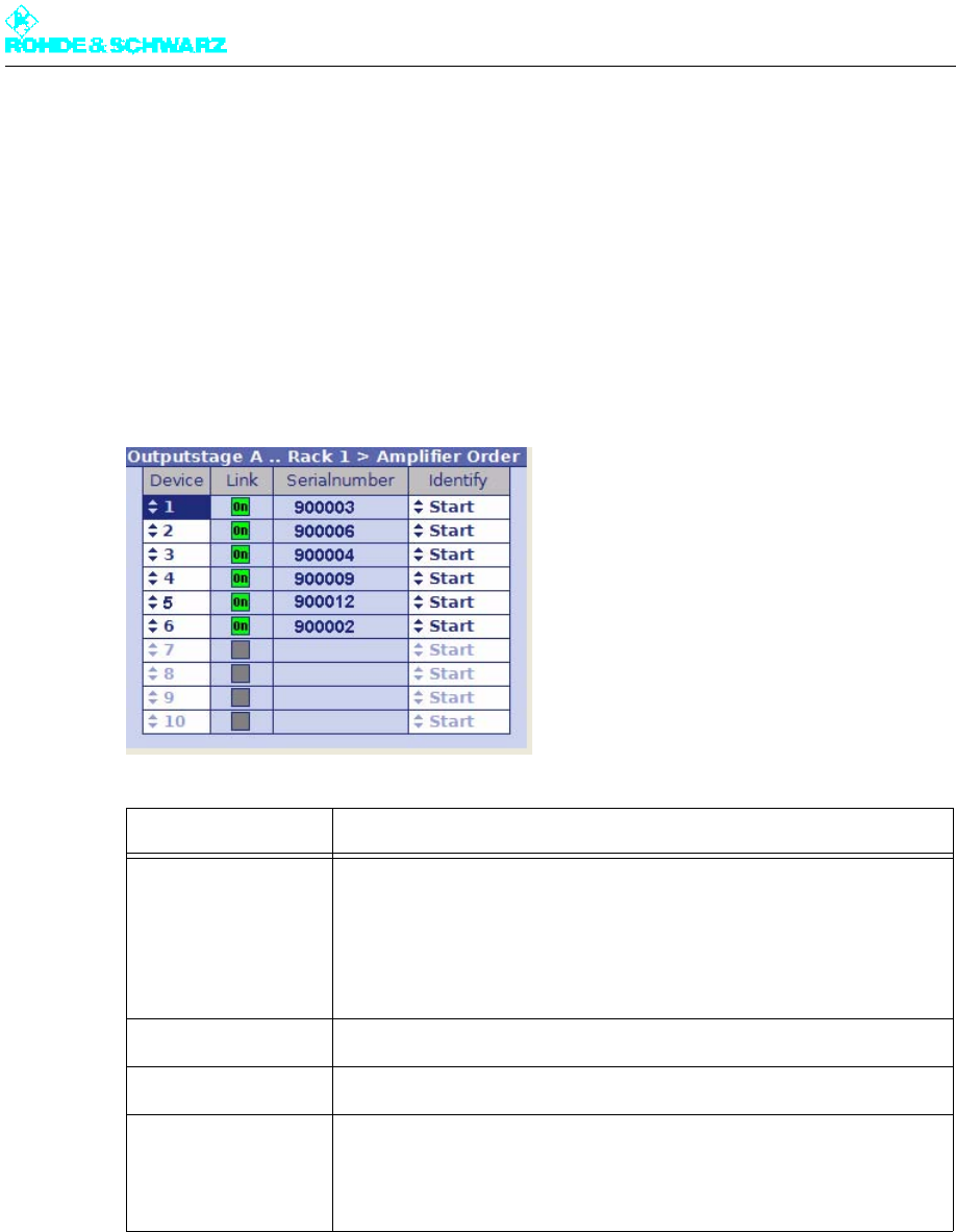
Chapter 5 Operating
2098.0720.72 - 5.108 - E-2
5.5.4 Rack Setup > Rack x > Amplifier Order Menu Window
After the transmitter system has been put into operation, entries for the amplifiers (of a par-
ticular rack) are displayed in the menu path for the output stage with consecutive numbering
(Amplifier 1 to max. Amplifier 4). Since the numbering is derived from the chronological
sequence in which the amplifiers can be detected on the CAN bus, it does not always cor-
respond to the sequence in which the amplifiers are physically arranged from top (= 1) to
bottom (= n) in the rack.
The Amplifier Order menu window is used to change the menu items for the amplifiers with
respect to the installation positions in the rack.
5.6 Measured Values Menu
You can use the Measured Values menu to read off measurement values.
Setting/display Explanation
Device Order number x (= 1 to n) of an amplifier; this number describes the
position of the associated amplifier menu in the menu path
By setting the order numbers correctly, it is possible to synchronize the
menu items (1 to n) and the associated installation positions (from top to
bottom).
Link Green: Amplifier is installed in the rack
Serial number Serial number of the amplifier (as indicated on the electronic type plate)
Identify Identification of an amplifier in the rack
If the Start switch is activated, the LEDs of the associated amplifier in
the rack flash.
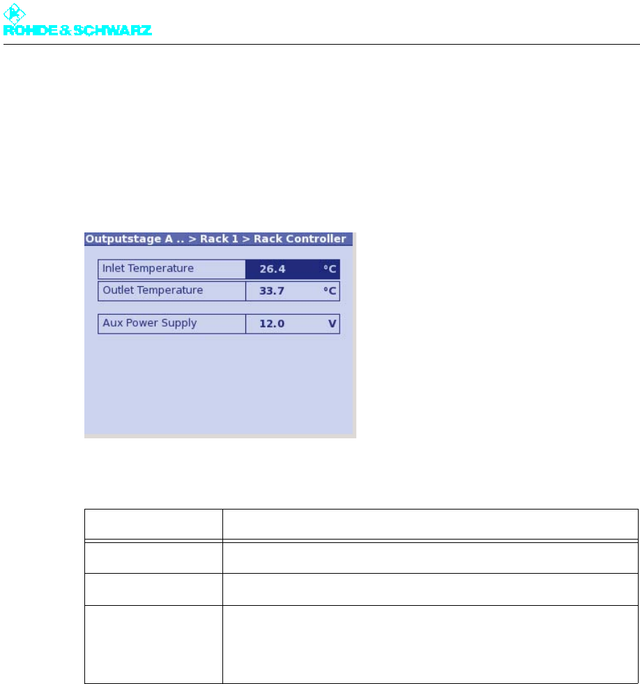
Chapter 5 Operating
2098.0720.72 - 5.109 - E-2
5.6.1 Measured Values/Rack Controller Menu Window
Outputstage A > Measured Values > Rack Measured Values > Rack x > Rack Control-
ler
The Measured Values/Rack Controller menu window displays the intake and exhaust air
temperatures and the control voltage of the transmitter rack.
The following table explains the meaning of the fields:
5.6.2 Measured Values/Amplifier x Menu Window
Outputstage A > Measured Values > Rack Measured Values > Rack x > Amplifier x
The Measured Values/Amplifier x menu window displays the measurement values for a
selected amplifier.
Display Explanation
Inlet Temperature Inlet temperature of the cooling medium (intake air)
Outlet Temperature Outlet temperature of the cooling medium (exhaust air)
Aux Power Supply Control voltage of the internal auxiliary power supply for the transmitter
rack
The value must be approx. 12 V.
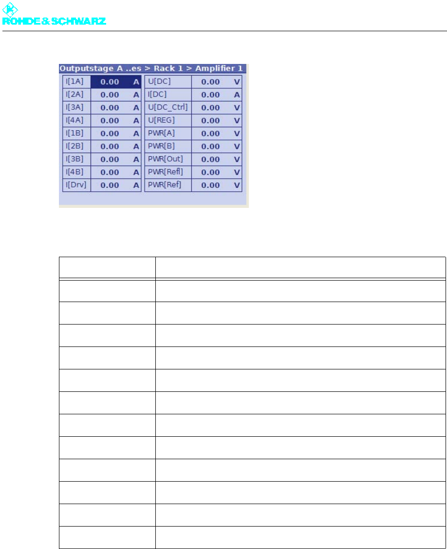
Chapter 5 Operating
2098.0720.72 - 5.110 - E-2
The following table explains the meaning of the fields:
5.7 Device Info Menu
You can use the Device Info menu to call for information on the transmitter rack.
Display Explanation
I[xA] Module current of an output stage module, x = 1 to 4 a)
a) With the amplifier type R&S VH8300A1, the measured current values I[4A] and I[1B] to I[4B] are not dis-
played.
I[xB] Module current of an output stage module, x = 1 to 4 a) b) c)
b) With the amplifier type R&S VH8200A1, the measured current values I[1B] and I[4B] are not displayed.
c) With the amplifier type R&S VM8530A1, the measured current values I[3B] and I[4B] are not displayed. The
displayed measurement values correspond to the individual transistor currents.
I[Drv] Current of the driver stage
U[DC] Supply voltage of the amplifier
I[DC] Total DC current
U[DC_CTRL] Reference voltage of the amplifier
U[REG] AGC voltage of the amplifier
PWR[A] Detector voltage of the power detector DET_A
PWR[B] Detector voltage of the power detector DED_B
PWR[Out] Forward voltage of the output-power detector
PWR[Refl] Reflected voltage of the reflected-power detector
PWR[Ref] Reference voltage of the output-power detector
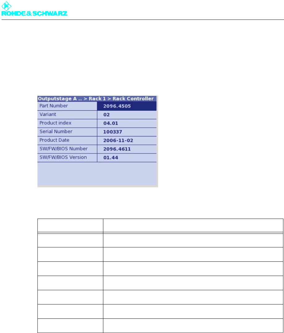
Chapter 5 Operating
2098.0720.72 - 5.111 - E-2
5.7.1 Device Info/Rack Controller Menu Window
Outputstage A > Device Info > Rack x > Rack Controller
You can use the Device Info/Rack Controller menu to call for information on the transmit-
ter rack.
The following table explains the meaning of the display fields:
5.7.2 Device Info/Amplifier x Menu Window
Outputstage A > Device Info > Rack x > Amplifier x
The Device Info/Amplifier x menu window provides device information for an amplifier.
Display Description
Part Number R&S stock number
Variant Model (basic model = 02)
Product Index Hardware amendment index
Serial Number Serial number
Product Date Date of production
SW/FW/BIOS Number R&S stock number for software, firmware or BIOS
SW/FW/BIOS Version Version number of software, firmware or BIOS
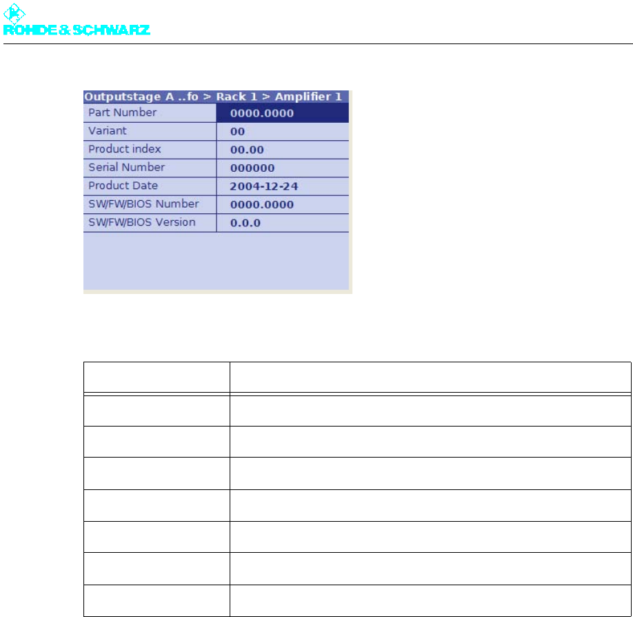
Chapter 5 Operating
2098.0720.72 - 5.112 - E-2
The following table explains the meaning of the display fields:
Display Explanation
Part Number R&S stock number
Variant Model (basic model = 02)
Product index Hardware change index
Serial Number Serial number
Product Date Date of production
SW/FW/BIOS Number R&S stock number for software, firmware or BIOS
SW/FW/BIOS Version Version number of software, firmware or BIOS
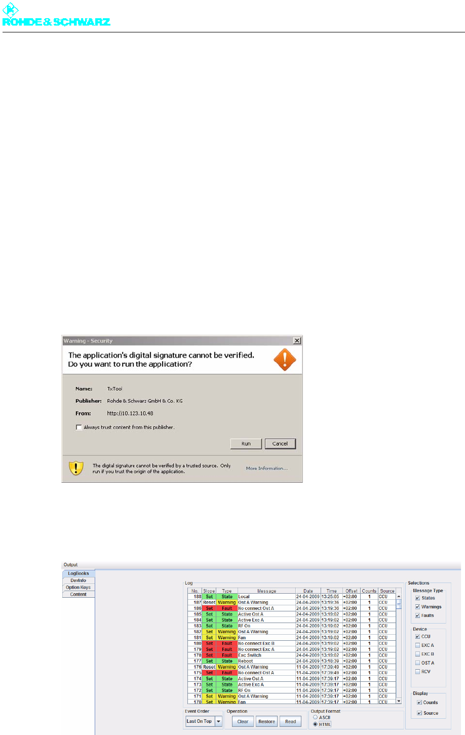
Chapter 5 Operating
2098.0720.72 - 5.113 - E-2
6 Other Menus
6.1 TxTool Menu: Saving Transmitter Information
In order to improve clarity and for archiving purposes, you can save transmitter data select-
ed via the web browser (such as logbook or device information, measurement values or pa-
rameters) to an ASCII or HTML file. You can also delete and restore logbook entries of the
transmitter components.
1. Select TxTool in the browser window.
A security query appears first of all.
Note Execution of the TxTool requires write rights to the file system of the computer. To grant
these rights you must confirm the security query.
If you select Always trust content from this author, the security query will not be dis-
played the next time the TxTool is called.
2. Confirm the security query with Run.
The TxTool window used to display and save transmitter data appears.

Chapter 5 Operating
2098.0720.72 - 5.114 - E-2
The window is initially empty when opened. The required settings must be selected before
the data is read out.
Reading out data
1. Select (top left) the data that is to be displayed.
Different windows containing additional functions are displayed depending on the type
of data you select. Depending on the selected tab, the window will still be empty (e.g.
LogBooks) or the appropriate data will be displayed (e.g. DeviceInfo).
2. Select (depending on the window) which data is to be displayed (see the table under
"Functions in Logbooks Window").
3. Start the readout of the data with Read.
Saving data
Different options and formats are available for saving the data.
1. Under Output Format, select the file format in which the data is to be saved.
2. In the Output menu, select whether the data is to be saved as a file (Write to File) or
copied to the clipboard (Copy to Clipboard).
Depending on your selection, you can save the data in a file using the Windows Save
command or copy it to the clipboard and then use it in other applications.
Note If the data is to be evaluated in a spreadsheet application (e.g. Microsoft Excel) it is ad-
visable to copy the data to the clipboard in HTML format. If the clipboard is then copied
to an (empty) worksheet, the values are separated in tabular form.
6.1.1 Functions in LogBooks Window
The following additional functions are available in the Logbooks window:
Function Explanation
Message Type Used to select the type of messages which are to be listed (more than
one option can be selected)
Device Used to select the transmitter components for which message data is to
be displayed (more than one option can be selected)
Content Type Filter Used to select the parameters or values which are to be displayed
Display Used to show and hide the columns Counts (shows the number of mes-
sages of this message type) and Source (shows the transmitter compo-
nent to which the message is assigned)
Last/First On Top Sorts the displayed messages according to the time at which they
occurred
Clear (Real) deletion of the logbook entries (identical to deleting the logbook
entries using the context menu of the Logbook menu window)
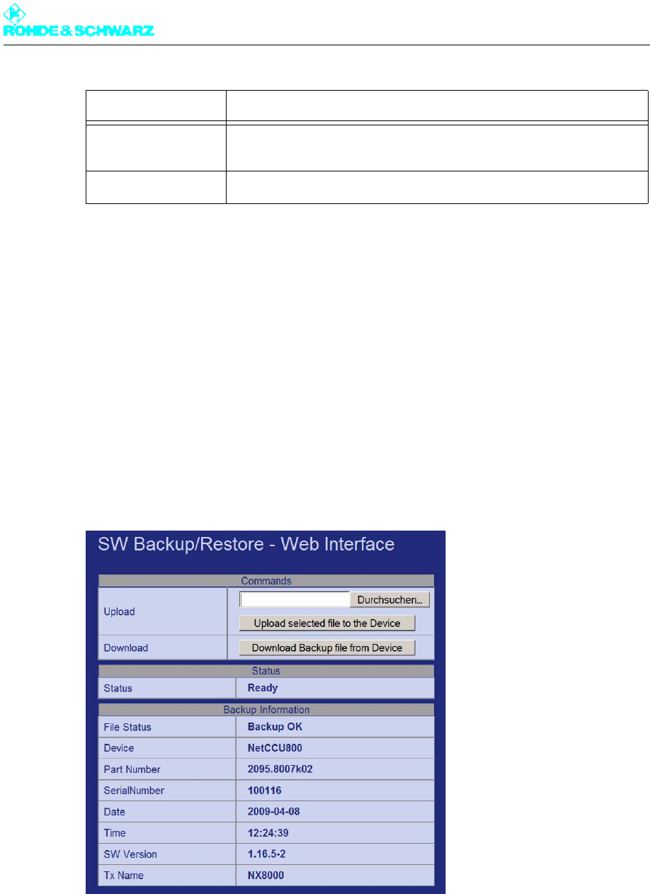
Chapter 5 Operating
2098.0720.72 - 5.115 - E-2
6.2 SW Backup/Restore Menu: Backing Up Complete
System
You can create a data/system backup file on the flash card of the R&S NetCCU800 and
save it on an external medium or restore it to the flash card by using the SW Backup/Re-
store browser menu.
Note You can create the data/system backup file in the SW Backup/Restore menu window of
the R&S NetCCU800 and from there also read it directly back into the R&S NetCCU800.
Select Backup / Restore in the browser window.
The SW Backup/Restore - Web Interface window is displayed.
The window displays the current status of the tool (Status) as well as the backup information
(Backup Information) related to the data/system backup file that is stored on the flash
card.
Copy the data/system backup file from the flash card to an external medium
1. Click on Download Backup file from the Device.
Restore (Real) restoration of the logbook entries (identical to restoring the log-
book entries using the context menu of the Logbook menu window)
Read Used to read out / update the displayed messages
Function Explanation

Chapter 5 Operating
2098.0720.72 - 5.116 - E-2
2. In the Windows dialog boxes that follow, select the desired file name and where you
want to save it.
The file will be saved at the selected location.
Copy the data/system backup file from an external medium to the flash card
1. Click on Browse.
2. Select the desired file in the Windows dialog boxes that follow.
The selected file is shown in the display area of the Upload window segment.
3. Click Upload selected file to the Device.
The file is saved on the R&S NetCCU800 flash card and can then be loaded into the
R&S NetCCU800 via the SW Backup/Restore menu window.
6.3 Storage Menu: Saving Exciter Data
You can use the R&S NetCCU800 to save parameter data of the exciter to an external me-
dium and to recall this data again when required.
Note This function is only available via the web browser.
The exciter must be connected to the R&S NetCCU800 and must be in remote mode.
Select Storage in the browser window.
The start window to save and recall exciter parameter data is displayed.
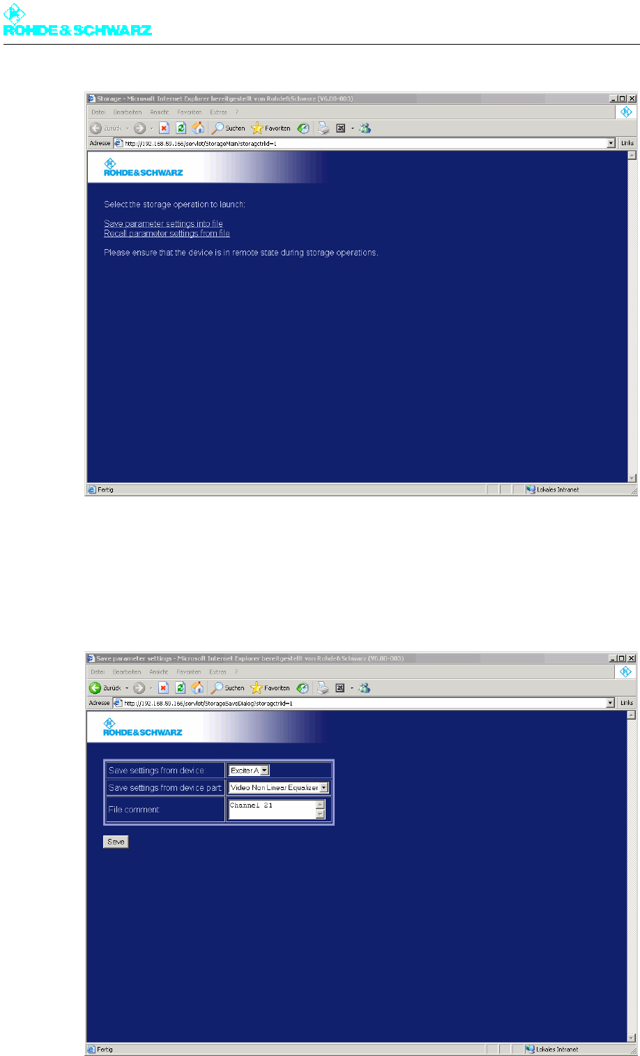
Chapter 5 Operating
2098.0720.72 - 5.117 - E-2
6.3.1 Saving Parameter Data
1. In the start window, select Save parameter settings into file.
A window opens from which you can select the parameter data you want to save.
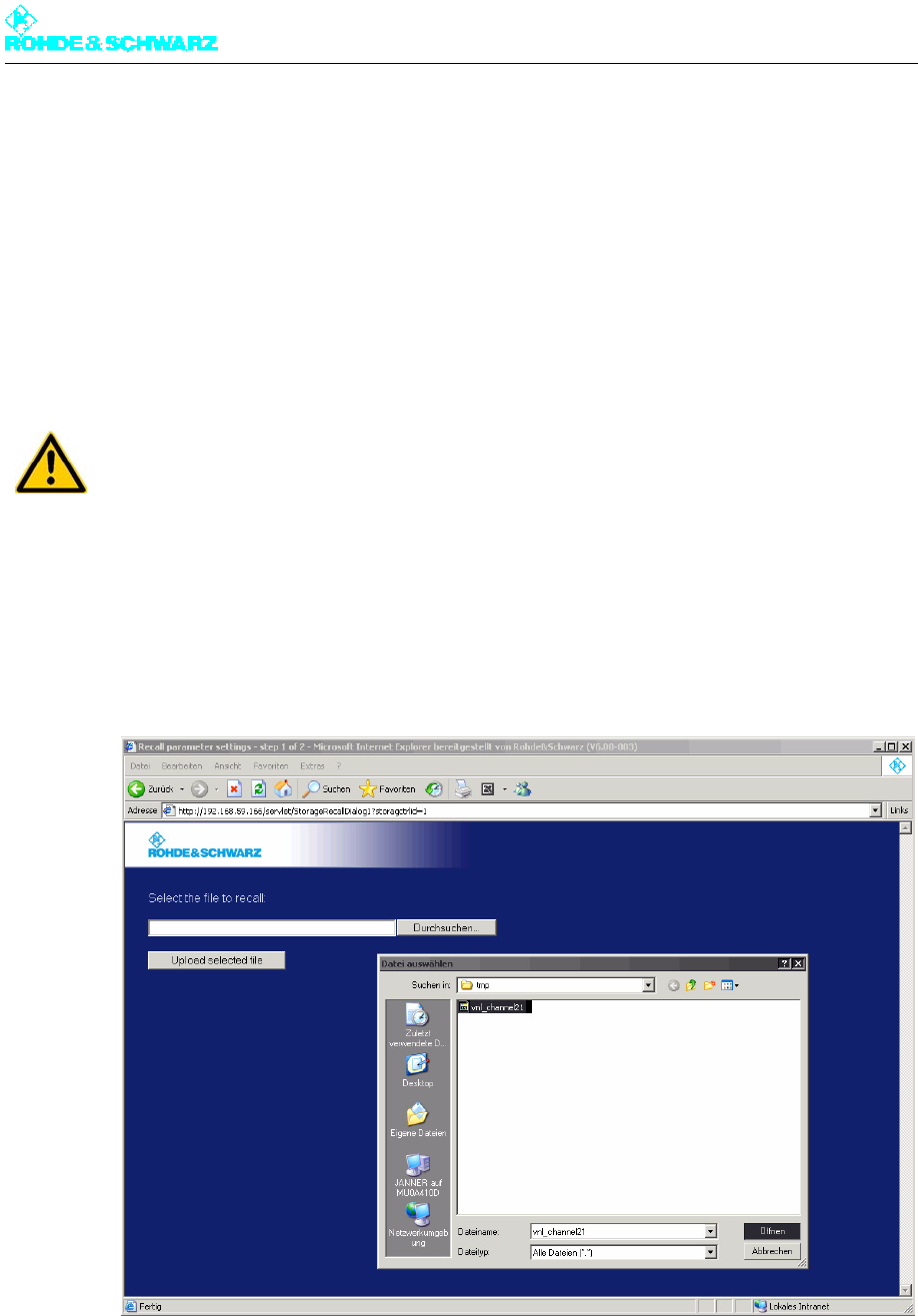
Chapter 5 Operating
2098.0720.72 - 5.118 - E-2
2. Select the required exciter and the parameter data set that you want to save.
3. Enter a unique comment about the selected parameter set to help you recognize the
content of the set or its intended use.
4. Click Save.
Use the Windows Save file as command to save the parameter set to a file.
6.3.2 Recalling Parameter Data
1. In the start window, select Recall parameter settings into file.
A window appears in which you can select which saved parameter data you want to re-
call to which exciter.
Note It is possible to import the parameter data of an exciter to a second exciter of the same
type.
2. Click Browse and select the required file.
3. Click Upload selected file to load the file.
A window is opened in which you can select the exciter to which the parameter data is
to be copied.
ATTENTION!
When parameter data is recalled, the current parameters of the selected exciter are over-
written without a warning message being displayed.
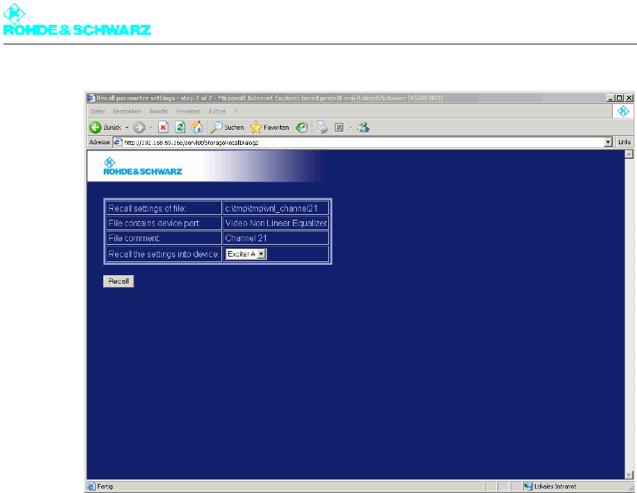
Chapter 5 Operating
2098.0720.72 - 5.119 - E-2
4. Select the exciter to which the parameter data is to be copied, and confirm with Recall.
The parameter data is copied to the selected exciter. The exciter is then automatically
rebooted.

Chapter 5 Operating
2098.0720.72 - 5.120 - E-2