Rohde and Schwarz NV830X UHF 1.8kW maximum Digital TV transmitter User Manual 32 SLX8000 12 12 07 01 00
Rohde & Schwarz Inc UHF 1.8kW maximum Digital TV transmitter 32 SLX8000 12 12 07 01 00
Contents
- 1. User Manual Part 1
- 2. User Manual Part 2
- 3. User Manual Part 3
User Manual Part 3

Broadcasting Division
2095.7346.32 - 6.0 - E-1
CHAPTER 6
MAINTENANCE
Printed in Germany

Chapter 6 Maintenance
2098.1190.72 - 6.01 - E-3
CONTENTS
1 Maintenance Intervals ..................................................................... 1
1.1 Maintenance of Subcontractor Products .....................................................1
2 Maintenance Tasks .......................................................................... 2
2.1 Replacing BIOS Battery in R&S NetCCU800 ................................................2
2.2 Replacing Fans on SX800 Exciter .................................................................2
2.3 Software Update .............................................................................................2

Chapter 6 Maintenance
2098.1190.72 - 6.02 - E-3

Chapter 6 Maintenance
2098.1190.72 - 6.1 - E-3
1 Maintenance Intervals
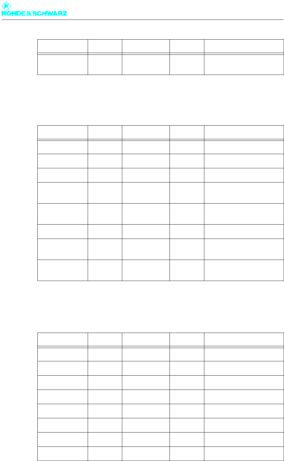
The following maintenance work must be performed at regular intervals:
1.1 Maintenance of Subcontractor Products
Subcontractor products such as external air filters must be maintained in accordance with
the maintenance instructions from the respective manufacturer and for the respective prod-
uct.
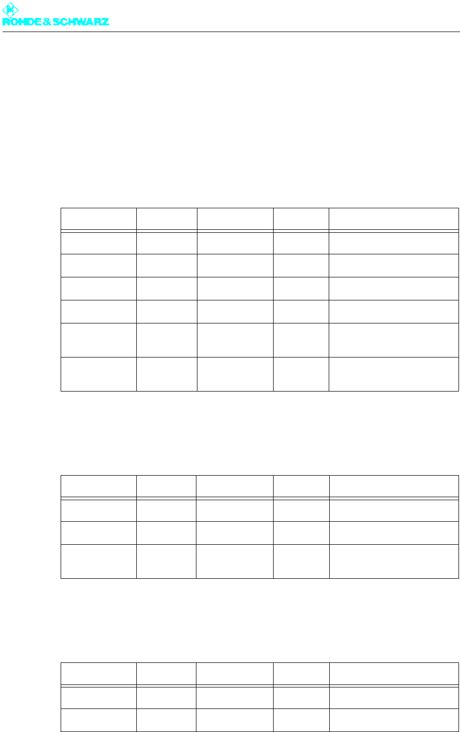
Maintenance interval Task Procedure described in:
2x per year Check the operating values (e.g.
output power, control values, etc)
1x per year Check and, if necessary, change
the backup battery of the transmit-
ter control unit (R&S NetCCU800)
Chapter "Maintenance" in the
R&S NetCCU800 manual
After 5 years and then
1x per year
Check whether the two rack fans
make noises when in operation;
replace them if necessary
Chapter "Service“ in this man-
ual
After 5 years and then
1x per year
Check whether the fans make
noises when in operation; replace
them if necessary
Chapter "Maintenance" in the
exciter manual

Chapter 6 Maintenance
2098.1190.72 - 6.2 - E-3
2 Maintenance Tasks
2.1 Replacing BIOS Battery in R&S NetCCU800
Note The chapter "Maintenance" in the R&S NetCCU800 manual describes how to replace the
BIOS battery.
2.2 Replacing Fans on SX800 Exciter
Note The chapter "Maintenance" in the exciter manual describes how to replace the fans.
2.3 Software Update
You can use the R&S NetCCU800 to install software updates for the R&S NetCCU800 itself
as well as for all exciters connected to the R&S NetCCU800. The update data is first trans-
ferred to the R&S NetCCU800. The update for the connected exciters is then performed in
a second step.
The software update is only possible if the R&S NetCCU800 is remotely connected to a net-
work client on which the new software and the program for performing the update are in-
stalled.
You perform a software update for the NSU/NCU in the same way. It is also possible to up-
date exciters via the NCU/NSU Update menu.
Note The update program was developed for performing updates of various Rohde&Schwarz
software solutions. For this reason, some functions of the program which are not relevant
to updating software via the R&S NetCCU800 are omitted in the description below.
The procedure for performing a software update is as follows.
1. Log on as Maintenance in the menu operation.
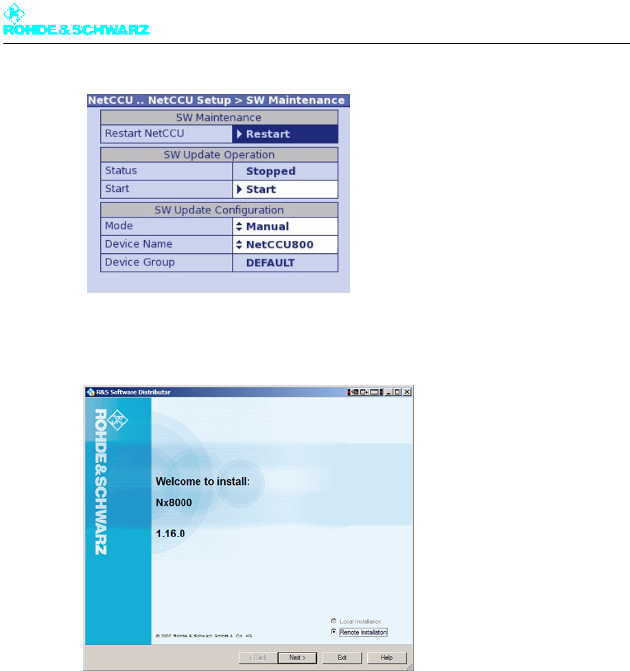
2. Call up NetCCU > NetCCU Setup > SW Maintenance.
3. Set the R&S NetCCU800 to Update mode using the Start function under SW Update
Operation.
Chapter 6 Maintenance
2098.1190.72 - 6.3 - E-3
4. Start the installation software on the client computer.
The start window of the R&S Software Distributor opens.
5. Confirm the default setting Remote Installation by clicking on Next.
The software updates that can be installed will be displayed. You can obtain additional
information about the update you select by highlighting it with the cursor and then click-
ing Info.

Chapter 6 Maintenance
2098.1190.72 - 6.4 - E-3
6. Select the required updates and confirm installation of the updates by clicking Next.
All instruments found in the network are displayed under the device name that you as-
signed in the Maintenance menu window.
7. Select the instrument and start the update by clicking Install.
After the update has been completed, a corresponding message will appear in the field
at the bottom left of the window. The R&S NetCCU800 is rebooted automatically.
If connected transmitter components cannot be found because the R&S NetCCU800 was
not in Update mode, the message "No R&S Device found" is displayed at the bottom left of
the window.
You have the following option:
1. On the R&S NetCCU800, open the menu NetCCU > NetCCU Setup > SW Mainte-
nance and start the Update mode using the Start function under SW Update Opera-
tion.

Chapter 6 Maintenance
2098.1190.72 - 6.5 - E-3
2. Click Rescan in the R&S Software Distributor window.
The special components are displayed and you can perform the update in the way de-
scribed above.
Note None of the remaining functions in the R&S Software Distribution window are relevant for
updates via the R&S NetCCU800; settings that can be accessed using these functions
must not be changed.
Performing software updates for exciters
When the update procedure described above is performed, the software updates for the ex-
citer(s) are also transferred to the R&S NetCCU800. The update for the exciter(s) is started
directly via the R&S NetCCU800.
1. Set the R&S NetCCU800 to the Update mode in the way described above.
2. Start the installation software.
3. Select the software package for the exciter.
4. Search for instruments in the network and select the exciter for which you want to per-
form a software update.
5. Install the update.
After the update procedure has been completed, the respective exciter is rebooted auto-
matically.

Chapter 6 Maintenance
2098.1190.72 - 6.6 - E-3

Broadcasting Division
2095.7346.32 - 7.0 - E-1
CHAPTER 7
TROUBLESHOOTING
Printed in Germany

Chapter 7 Troubleshooting
2098.1190.72 - 7.01 - E-1
CONTENTS
1 Information ....................................................................................... 1

Chapter 7 Troubleshooting
2098.1190.72 - 7.1 - E-1
1 Information
Troubleshooting information will be provided at a later date.

Broadcasting Division
2095.7346.32 - 8.0 - E-1
CHAPTER 8
SERVICE
Printed in Germany

Chapter 8 Service
2098.0188.72 - 8.01 - E-1
CONTENTS
1 Necessary Tools and Test Equipment ........................................... 1
2 Overview ........................................................................................... 2
3 Preparations ..................................................................................... 3
3.1 Safety ...............................................................................................................3
3.2 Rack Cabling ...................................................................................................3
3.3 Removing Front Panel/Rear Panel ................................................................4
4 Power Distribution ........................................................................... 5
4.1 Replacing Main Switch ...................................................................................5
4.1.1 Removing Main Switch .................................................................................5
4.1.2 Installing Main Switch ...................................................................................6
4.2 Replacing Motor Protection Switches ..........................................................7
4.2.1 Removing Motor Protection Switch ..............................................................7
4.2.2 Installing Motor Protection Switch ................................................................9
4.3 Replacing Power Distribution Board ..........................................................10
4.3.1 Removing Power Distribution Board ..........................................................10
4.3.2 Installing Power Distribution Board ............................................................11
4.4 Replacing Automatic Line Fuses ................................................................12
4.4.1 Removing Automatic Line Fuse .................................................................12
4.4.2 Installing Automatic Line Fuse ...................................................................13
4.5 Replacing Auxiliary Power Supply Unit .....................................................13
4.5.1 Removing Auxiliary Power Supply Unit ......................................................13
4.5.2 Installing the Auxiliary Power Supply Unit ..................................................14
5 Transmitter Control Unit ............................................................... 15
5.1 Replacing R&S NetCCU800 .........................................................................15
5.1.1 Removing R&S NetCCU800 ......................................................................15
5.1.2 Preparing R&S NetCCU800 for Installation ................................................16
5.1.3 Installing R&S NetCCU800 ........................................................................17
5.2 Replacing Rack Controller ...........................................................................17
5.2.1 Removing Rack Controller .........................................................................17
5.2.2 Installing Rack Controller ...........................................................................18

Chapter 8 Service
2098.0188.72 - 8.02 - E-1
6 Exciter Components ...................................................................... 19
6.1 Replacing Exciter .........................................................................................19
6.1.1 Removing Exciter .......................................................................................19
6.1.2 Configuring Exciter .....................................................................................20
6.1.3 Installing Exciter .........................................................................................21
6.2 Replacing Exciter Switch .............................................................................21
6.2.1 Removing Exciter Switch ............................................................................21
6.2.2 Installing Exciter Switch ..............................................................................22
7 Output Stage Components ........................................................... 23
7.1 Replacing Amplifiers ....................................................................................23
7.1.1 Removing Amplifier ....................................................................................23
7.1.2 Installing Amplifier ......................................................................................24
7.2 Replacing Absorber .....................................................................................24
7.2.1 Removing Absorber ....................................................................................24
7.2.2 Installing Absorber ......................................................................................25
8 Harmonics Filter ............................................................................ 26
8.1 Replacing Harmonics Filter .........................................................................26
8.1.1 Removing Harmonics Filter ........................................................................26
8.1.2 Installing Harmonics Filter ..........................................................................27
9 Cooling System .............................................................................. 28
9.1 Replacing Fans .............................................................................................28
9.1.1 Removing Fan ............................................................................................28
9.1.2 Installing Fan ..............................................................................................30
9.2 Replacing Starting Capacitors ....................................................................30
9.2.1 Removing Starting Capacitor .....................................................................30
9.2.2 Installing Starting Capacitor .......................................................................31
9.3 Replacing Differential Pressure Gages ......................................................31
9.3.1 Removing Differential Pressure Gage ........................................................32
9.3.2 Installing Differential Pressure Gage ..........................................................32
9.4 Replacing Temperature Sensors ................................................................33
9.4.1 Removing Temperature Sensor .................................................................33
9.4.2 Installing Temperature Sensor ...................................................................34

Chapter 8 Service
2098.0188.72 - 8.1 - E-1
1 Necessary Tools and Test Equipment
The specified tools and test equipment include only those items needed for removing sys-
tem components and carrying out simple checks on them.
Depending on the service work to be performed, you will require the following tools:
Screwdriver No. 0
Screwdriver No. 1
Screwdriver No. 2
Phillips screwdriver No. 0
Phillips screwdriver No. 1
Phillips screwdriver No. 2
Torx screwdriver No. 8
Torx screwdriver No. 9
Torx screwdriver No. 20
Hexagonal socket No. 3
Hexagonal socket No. 6
Open-end wrench No. 7
Open-end wrench No. 8
Open-end wrench No. 13
Multimeter

Chapter 8 Service
2098.0188.72 - 8.2 - E-1
2 Overview
You can remove and exchange the following units and transmitter components if errors oc-
cur:
Power distribution
– Main switch
– Motor protection switches
– Automatic line fuses
– Power distribution board
– Auxiliary power supply
Transmitter control unit
– R&S NetCCU800
– Rack controller
Exciter components
–Exciter
– Exciter switch (for exciter standby)
Output stage components
– Amplifiers
– Absorber
Harmonics filter
Cooling system
–Fans
–Starting capacitors
– Differential pressure gages
– Temperature sensors
Chapter 8 Service
2098.0188.72 - 8.3 - E-1
3 Preparations
3.1 Safety
Note Full information on the subject of safety can be found in the section "Safety".
3.2 Rack Cabling
The standard components of the transmitter are fully cabled together on delivery. You need
to reconnect the separate replacement instruments during service work.
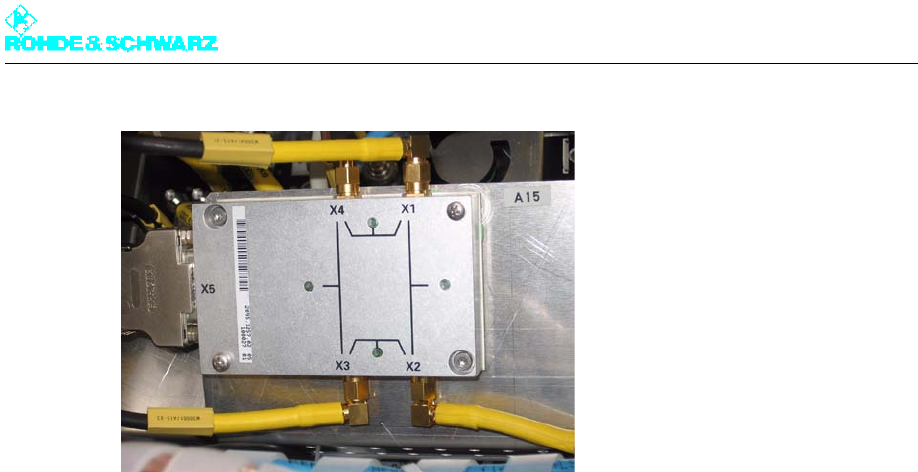
Each cable has a yellow collar at each end, inscribed with the cable number (W...) and the
intended purpose (module number A..., connector number X...). This makes it easier to
connect the cable concerned to the intended slot or connection point, since the modules
are provided with an engraved or self-adhesive circuit diagram.
For easy connection of replacement instruments or devices proceed as follows:
1. Find the plug (connector) number from the yellow collar on the cable.
2. Find the same number on the instrument you wish to connect (by looking for the female
connector or circuit diagram).
3. Insert the plug connector into the corresponding female connector.
WARNING!
All service work should only be carried out by qualified personnel and only on components
that have been disconnected from the power supply. Heavy components such as amplifi-
ers must always be exchanged using a team of two people.
Chapter 8 Service
2098.0188.72 - 8.4 - E-1
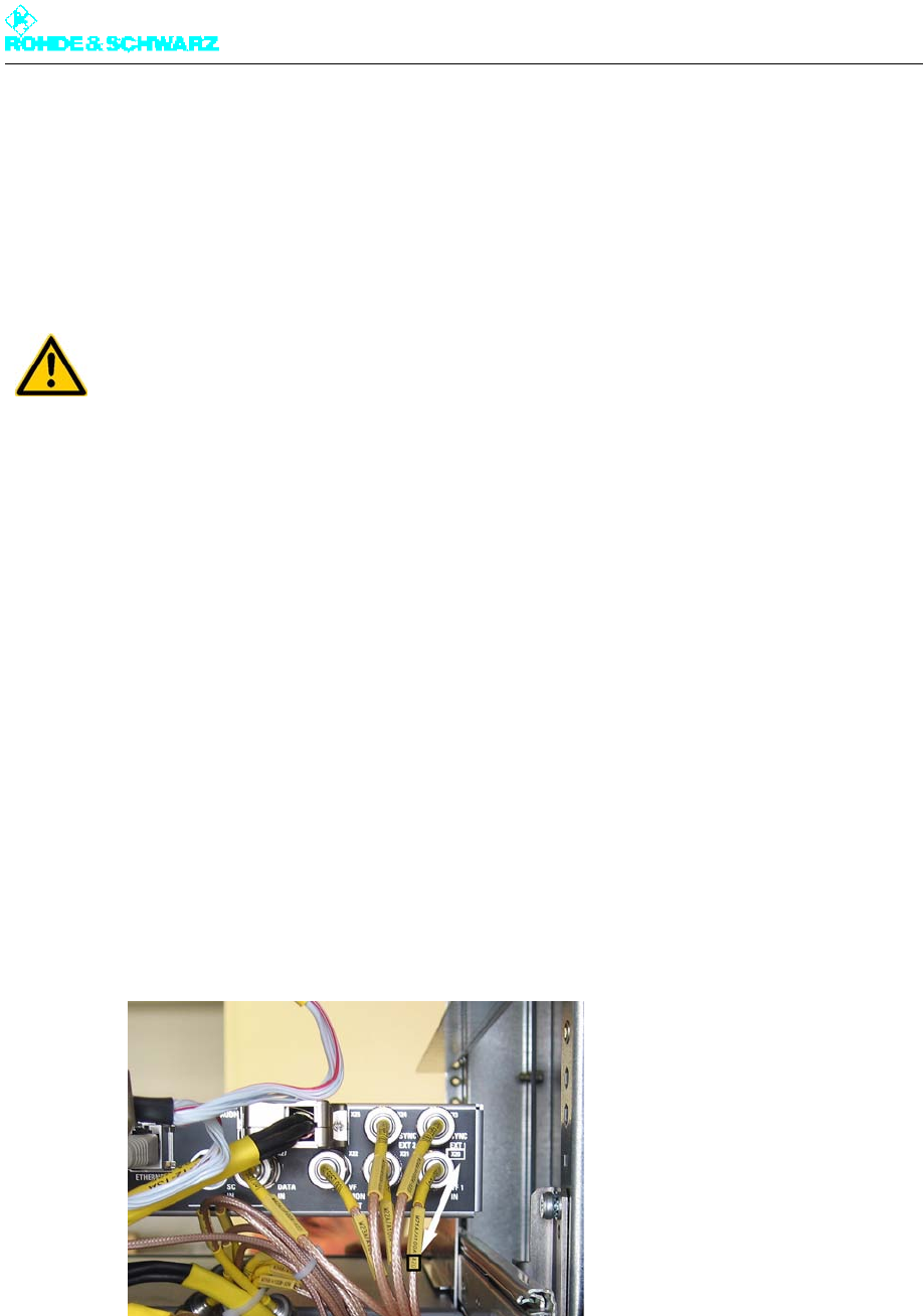
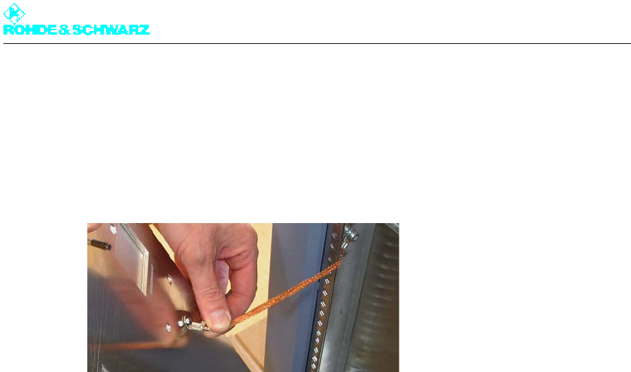
3.3 Removing Front Panel/Rear Panel
To remove the front panel/rear panel proceed as follows:
Using a Torx screwdriver No. 20, remove the front or rear panel.
Fig. 1 Ground terminal of a front panel/rear panel
Chapter 8 Service
2098.0188.72 - 8.5 - E-1
4 Power Distribution
You can replace the following power distribution components:
Main switch (power supply terminal)
Motor protection switch
Automatic line fuse
Power distribution board
Auxiliary power supply
4.1 Replacing Main Switch
4.1.1 Removing Main Switch
To remove the main switch proceed as follows:
1. Using a Torx screwdriver No. 20, remove the front panel of the power distribution.
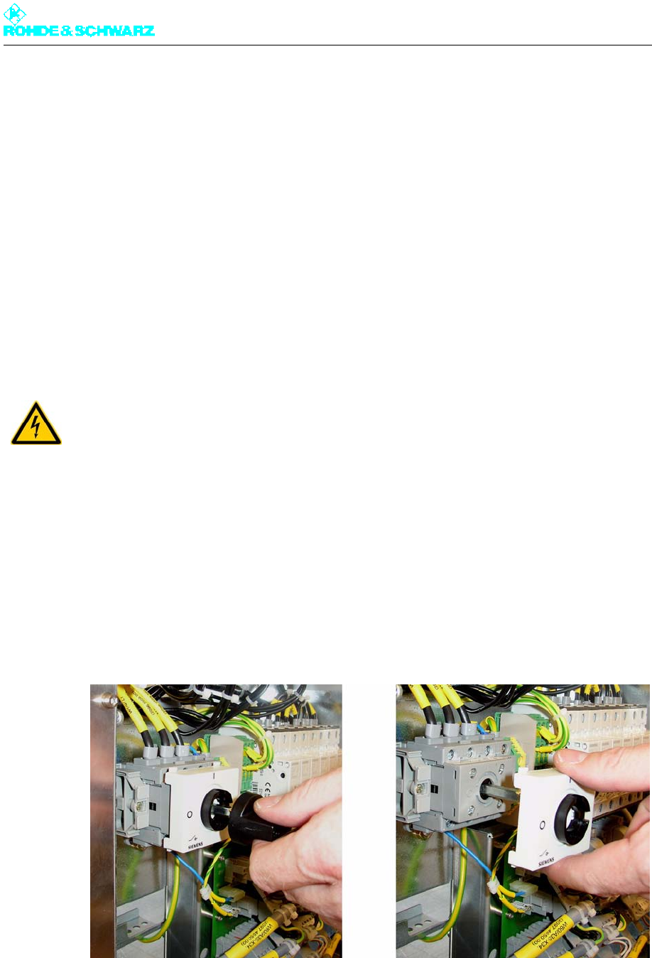
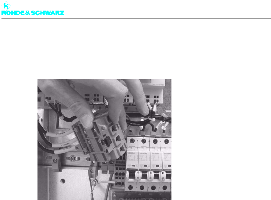
2. Unscrew the rotary knob and the main switch cover.
Fig. 2 Unscrewing the rotary knob and cover
3. Undo the screws on the switch housing (Phillips screwdriver No. 1) and remove the con-
nected cables.
WARNING!
Always make sure that the power supply is disconnected before commencing any service
work on the transmitter rack. This will prevent injury due to electric shock and avoid dam-
age to the instruments.
Chapter 8 Service
2098.0188.72 - 8.6 - E-1
4. Undo the screws on the terminal rack on the left of the main switch and slide the terminal
rack to the left.
5. Pull forward the black stop lever on the underside of the main switch.
6. Carefully take out the main switch.
Fig. 3 Taking out the main switch
4.1.2 Installing Main Switch
1. Replace the main switch by proceeding in the reverse order.
2. Insert the cables into the corresponding openings and fasten them with screws.
Note Notice how the cables are labeled and make sure they are in the right sequence, since
two of the three phase cables are the same color (black).
3. Measure the rotary field with the aid of a rotary field meter.
If the rotary field is correct, continue with the next step; if it is wrong, swap two wires from
the cable and measure the rotary field again.
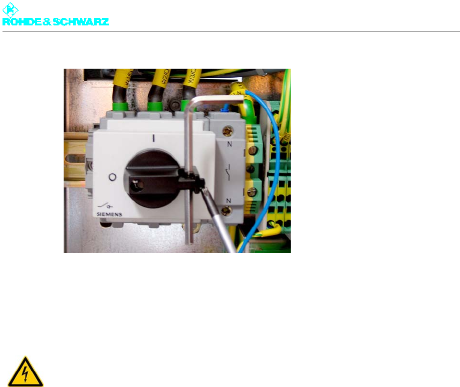
4. Screw the main switch cover and the rotary knob back on.
Note When working on the transmitter rack the main switch can be locked in the "OFF" posi-
tion (see next figure).
Chapter 8 Service
2098.0188.72 - 8.7 - E-1
Fig. 4 Main switch locked
4.2 Replacing Motor Protection Switches
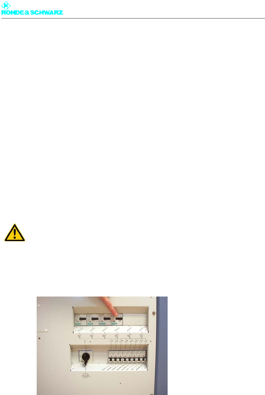
4.2.1 Removing Motor Protection Switch
To remove the motor protection switch proceed as follows:
1. Using a Torx screwdriver No. 20, remove the front panel of the power distribution.
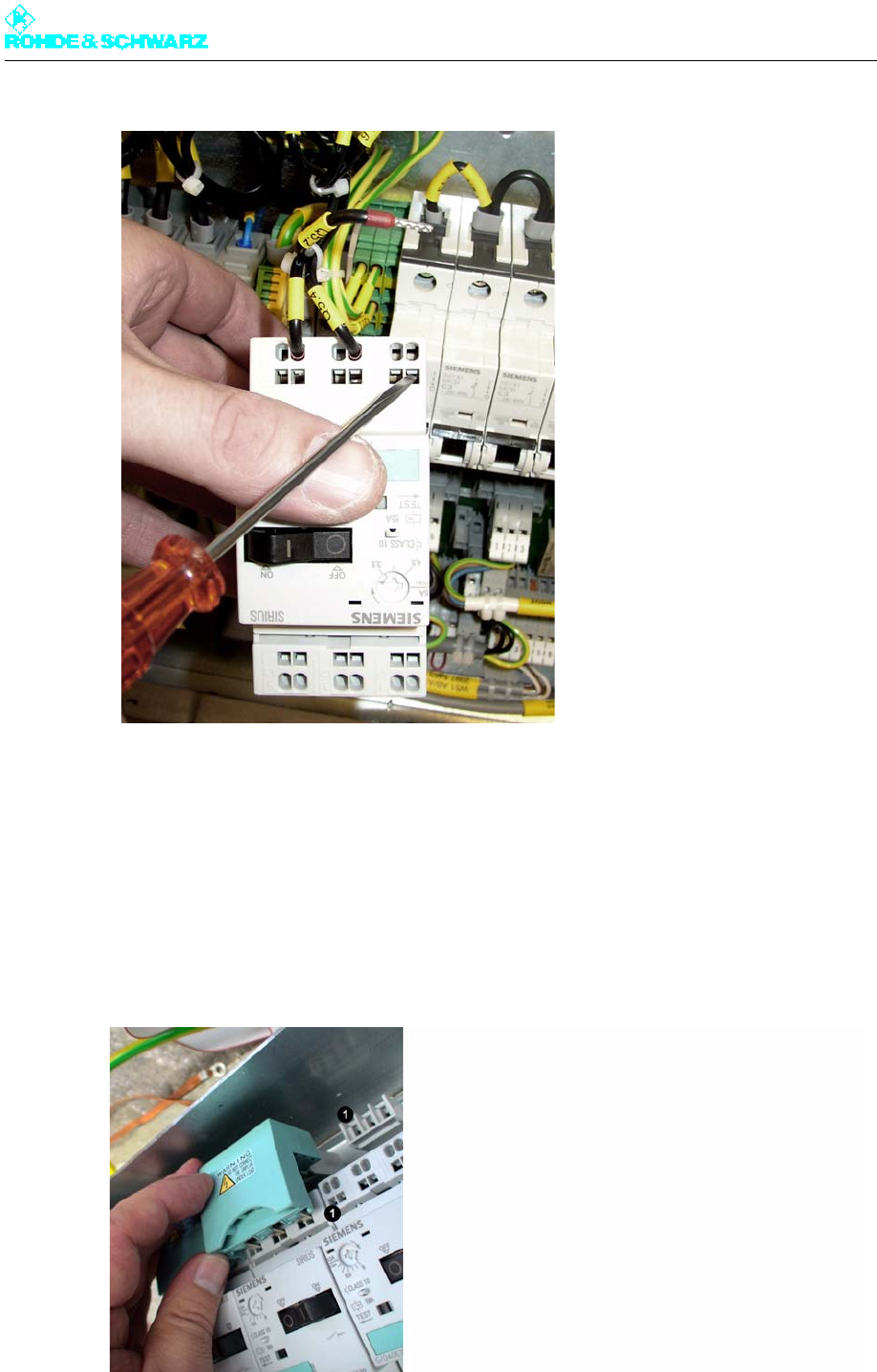
2. Pull the blue-green shorting plug forward.
If necessary you may use a screwdriver (No. 0) suited to the relatively high amounts of
force that are needed.
WARNING!
Always make sure that the power supply is disconnected before commencing any service
work on the transmitter rack. This will prevent injury due to electric shock and avoid dam-
age to the instruments.
Chapter 8 Service
2098.0188.72 - 8.8 - E-1
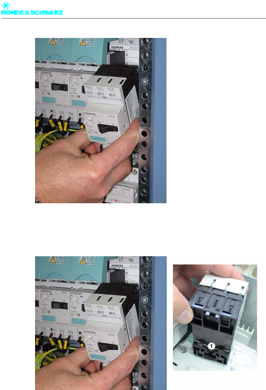
3. Press the motor protection switch sharply downward and pull it forward by the bottom
edge.
Because there is a spring clip behind the upper edge, you can only release the switch
downward.
1) Spring clip
4. Use a screwdriver to open the cable clamps and pull out the connected cable (see fig-
ure).
Chapter 8 Service
2098.0188.72 - 8.9 - E-1
Fig. 5 Opening the cable clamp on the motor protection switch
4.2.2 Installing Motor Protection Switch
Replace the motor protection switch by proceeding in the reverse order.
Note When replacing, feed the shorting plug right in and push the switch into place with some
force.
Fig. 6 Installing the motor protection switch
Chapter 8 Service
2098.0188.72 - 8.10 - E-1
1) Room for the shorting plug pins
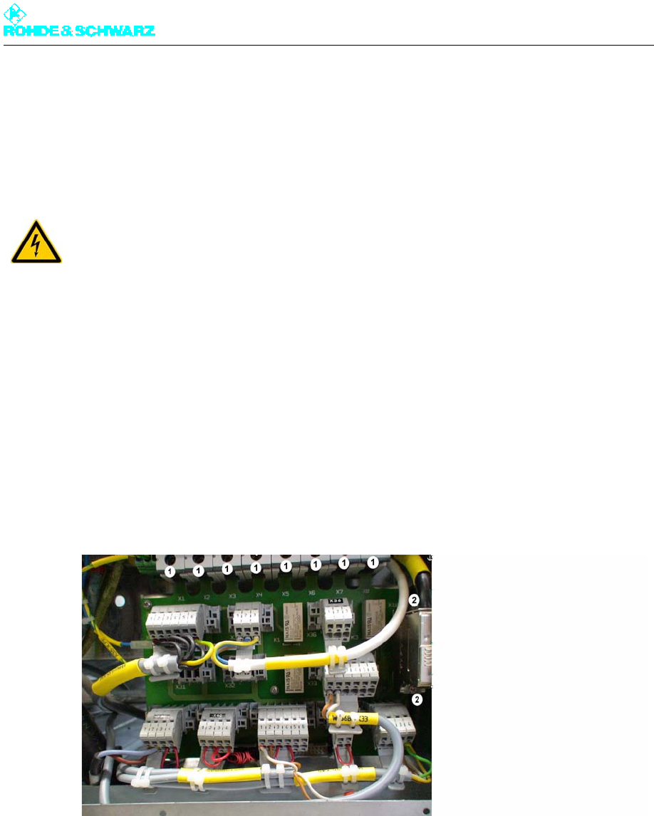
4.3 Replacing Power Distribution Board
4.3.1 Removing Power Distribution Board
To remove the power distribution board proceed as follows:
1. Using a Torx screwdriver No. 20, remove the front panel of the power distribution.
2. Remove all plugs before removing the power distribution board.
3. Unscrew the SUB-D connector on the right of the longitudinal edge (two screws).
4. Use a Phillips screwdriver No. 1 to undo eight screws on the automatic line fuses.
Fig. 7 Removing the power distribution board
1) Screws on the automatic line fuses
2) Screws on the SUB-D connector
5. Using a Torx screwdriver No. 8 remove seven fixing screws from the power distribution
board.
WARNING!
Always make sure that the power supply is disconnected before commencing any service
work on the transmitter rack. This will prevent injury due to electric shock and avoid dam-
age to the instruments.
Chapter 8 Service
2098.0188.72 - 8.11 - E-1
Fig. 8 Removing the power distribution board
1) Fixing screws on the power distribution board
6. To take out the PCB, first slide it downward.
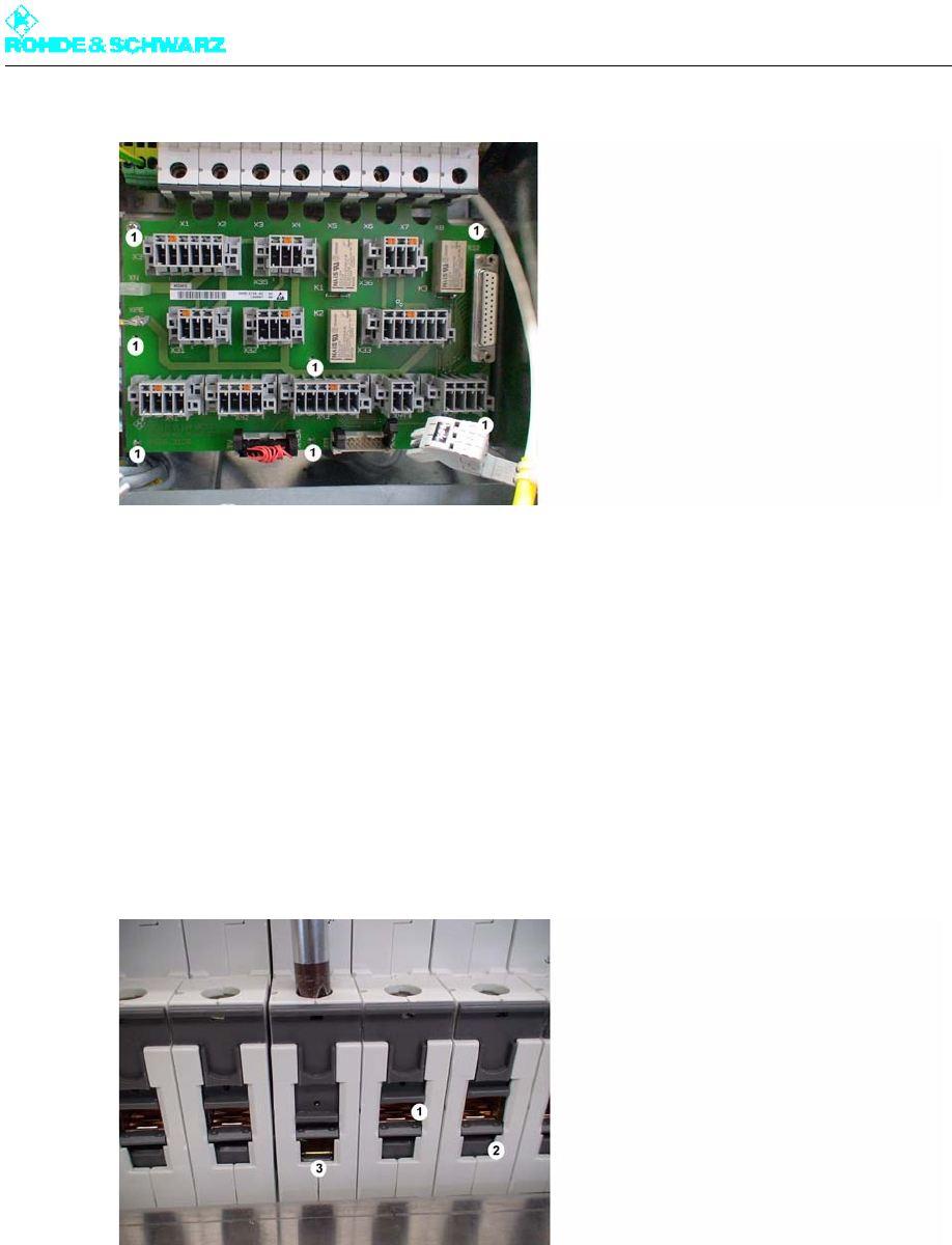
4.3.2 Installing Power Distribution Board
Replace the power distribution board by proceeding in the reverse order.
Note When replacing the power distribution board, make sure that it feeds into the right slots.
Fig. 9 Installing the power distribution board
1) Wrong
2) Right
3) Pressing with a screwdriver visibly opens the right chamber
Chapter 8 Service
2098.0188.72 - 8.12 - E-1
4.4 Replacing Automatic Line Fuses
4.4.1 Removing Automatic Line Fuse
Note Before removing an automatic line fuse, the power distribution board must be removed (see
"Removing the Power Distribution Board").
To remove the automatic line fuse proceed as follows:
1. Remove the power distribution board.
2. From above, grip the back of the automatic line fuse you wish to remove and undo the
white plastic springs.
3. Remove the automatic line fuse.
WARNING!
Always make sure that the power supply is disconnected before commencing any service
work on the transmitter rack. This will prevent injury due to electric shock and avoid dam-
age to the instruments.
Chapter 8 Service
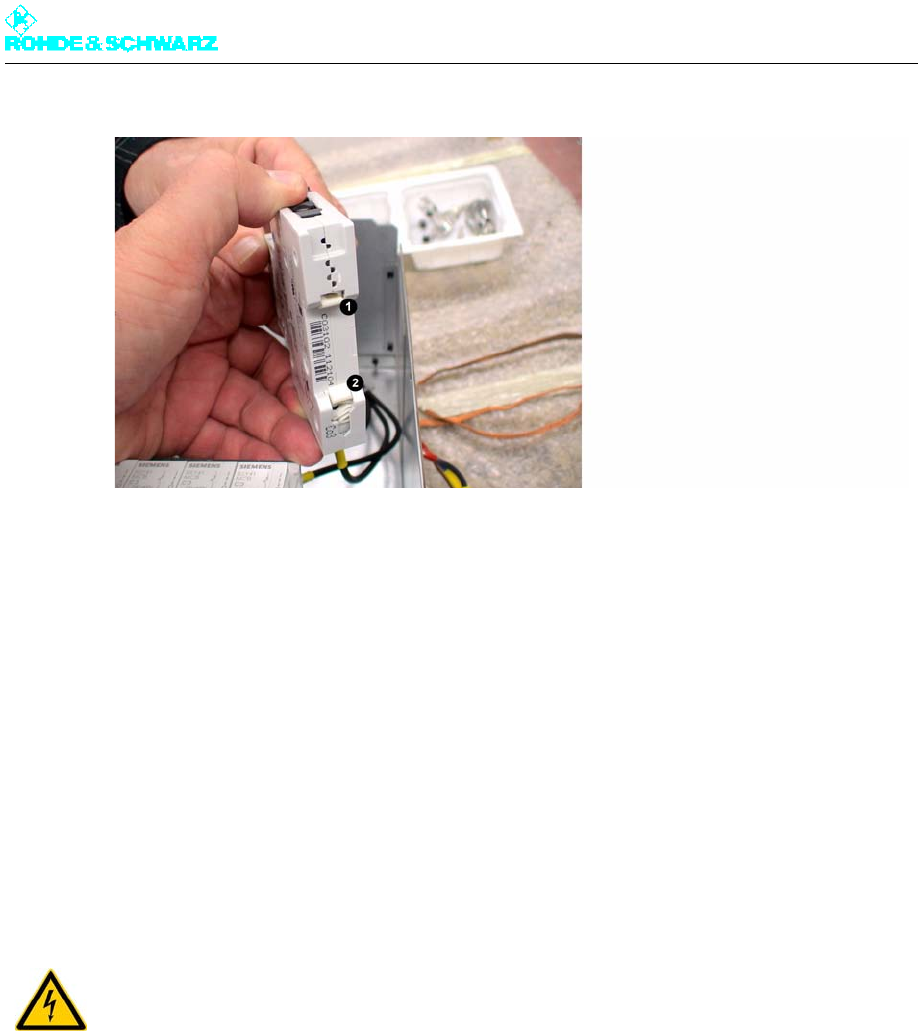
2098.0188.72 - 8.13 - E-1
Fig. 10 Automatic line fuse
1) Upper plastic spring
2) Lower plastic spring
4.4.2 Installing Automatic Line Fuse
Replace the automatic line fuse by proceeding in the reverse order.
Note Before putting it back into operation, make sure that all terminals are correctly connected.
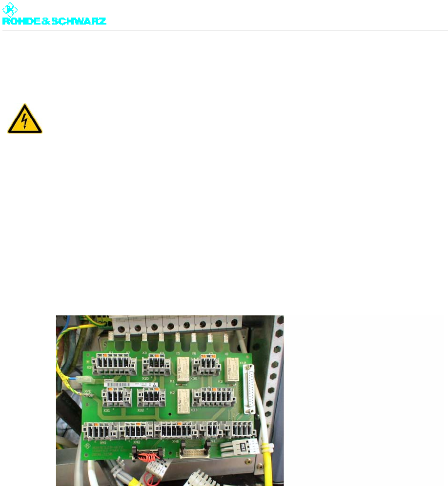
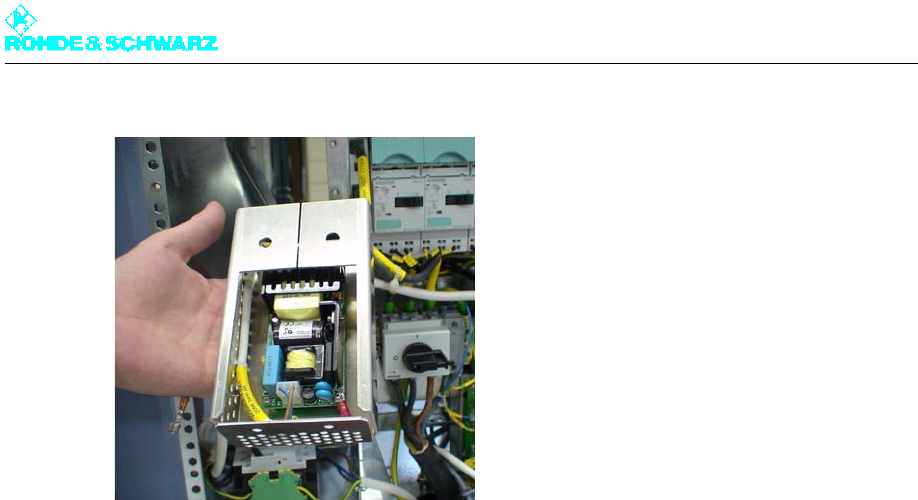
4.5 Replacing Auxiliary Power Supply Unit
4.5.1 Removing Auxiliary Power Supply Unit
To remove the auxiliary power supply proceed as follows:
1. Using a Torx screwdriver No. 20, remove the front panel of the power distribution.
2. Undo the auxiliary power supply cables (X35, X45) from the power distribution board.
Trace the two cables and if necessary cut off the cable ties.
3. Undo two Torx screws on the front of the power supply unit.
4. Remove the power supply unit.
WARNING!
Always make sure that the power supply is disconnected before commencing any service
work on the transmitter rack. This will prevent injury due to electric shock and avoid dam-
age to the instruments.
Chapter 8 Service
2098.0188.72 - 8.14 - E-1
Fig. 11 Removing the power supply unit
4.5.2 Installing the Auxiliary Power Supply Unit
Replace the power supply unit by proceeding in the reverse order.

Chapter 8 Service
2098.0188.72 - 8.15 - E-1
5 Transmitter Control Unit
You can replace the following transmitter control unit components:
R&S NetCCU800
Rack controller
5.1 Replacing R&S NetCCU800
5.1.1 Removing R&S NetCCU800
Note Removing the R&S NetCCU800 does not affect transmitter operation.
1. Switch off automatic line fuse F1.
2. Undo the two captive screws (Torx screwdriver No. 20) at the front brackets of the R&S
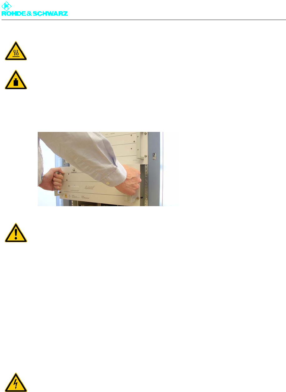
NetCCU800 and exciter (the screws are next to the handles).
3. Grip the handles and slowly pull the rackmount out of the rack as far as it will go (the
guide rails engage and are locked in place).
4. Disconnect the power cable from the rear panel of the R&S NetCCU800.
5. Disconnect all cables from the rear panel of the R&S NetCCU800.
WARNING!
Always make sure that the power supply is disconnected before commencing any service
work on the transmitter rack. This will prevent injury due to electric shock and avoid dam-
age to the instruments.
Chapter 8 Service
2098.0188.72 - 8.16 - E-1
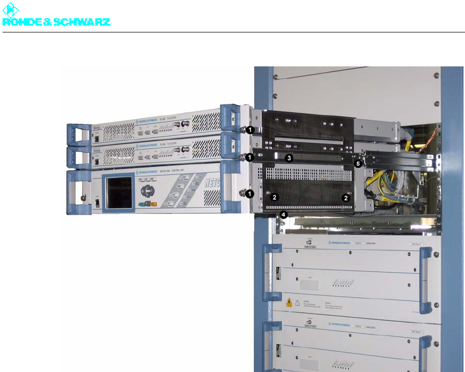
Fig. 12 Removing R&S NetCCU800 from transmitter rack
1) Captive screws at front panel of installed units (here: exciter and R&S NetCCU800)
2) Screws securing R&S NetCCU800 to rackmount
3) Guide rails
4) Support bracket for R&S NetCCU800
5) Safety lever for releasing guide rail catch
6. Undo the two fastening screws (Torx screwdriver No. 9) from the rackmount on both
sides of the R&S NetCCU800.
Note Removal should be performed by two persons. When pulled out by the handles, the R&S
NetCCU800 must be supported from below as soon as the support brackets no longer
support it.
7. Pull the R&S NetCCU800 out of the rackmount.
5.1.2 Preparing R&S NetCCU800 for Installation
The replacement R&S NetCCU800 is delivered as a desktop unit and must be prepared for
installation as follows.
Remove the protective rubber caps on the rear feet of the instrument.
The replacement unit is as a rule preconfigured with the default configuration. So that the
new R&S NetCCU800 does not adversely affect the operation of the transmitter when it is
put into operation in the transmitter rack, it must first be configured specifically for the trans-
mitter.
Chapter 8 Service
2098.0188.72 - 8.17 - E-1
Put the R&S NetCCU800 into local mode and configure the unit specifically for the trans-
mitter concerned, as described in the chapter "Commissioning".
5.1.3 Installing R&S NetCCU800
To install the unit in the transmitter, reverse the procedure used to remove it.
1. Slide the R&S NetCCU800 horizontally into the rackmount on the lowest support brack-
ets until the screw holes in the plug-in housing and on the side panels of the R&S
NetCCU800 line up.
2. Fasten the R&S NetCCU800 with two screws on each side.
3. Connect the cables to the R&S NetCCU800 according to the labeling (see yellow cable
collars).
4. Undo the latch on the guide rails. Push down the safety lever on the right while simulta-
neously pushing up the safety lever on the left and slide the rackmount into the rack.
5. Retighten the two captive screws on the front panel of the R&S NetCCU800 and exciter.
6. Switch the automatic line fuse F1 on again.
5.2 Replacing Rack Controller
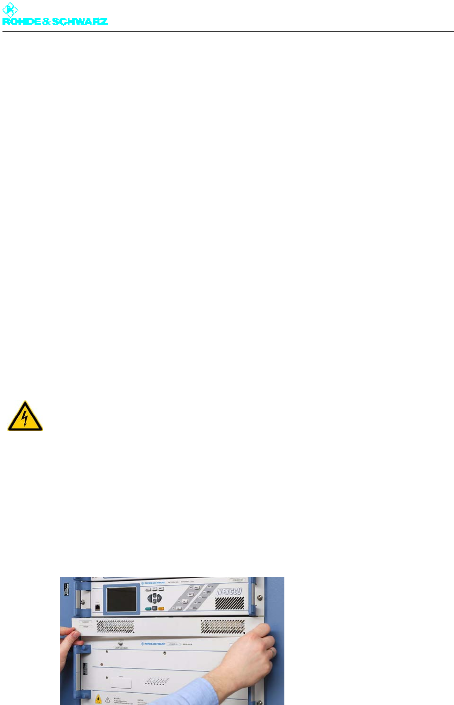
5.2.1 Removing Rack Controller
Note The rack controller is underneath the R&S NetCCU800.
1. Remove the cover by undoing the two screws (Torx screwdriver No. 20).
Fig. 13 Removal of rack controller from transmitter rack: removing cover
WARNING!
Always make sure that the power supply is disconnected before commencing any service
work on the transmitter rack. This will prevent injury due to electric shock and avoid dam-
age to the instruments.
Chapter 8 Service
2098.0188.72 - 8.18 - E-1
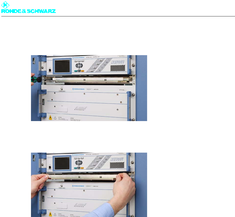
2. Turn the two screws (Torx screwdriver No. 20) on the sides alternately by a few turns.
This pushes the rack controller out of the rack and prevents it from tilting.
Fig. 14 Removal of rack controller from transmitter rack: undoing fastening screws
3. Remove the rack controller from the rack.
Fig. 15 Removal of rack controller from transmitter rack: removing rack controller
5.2.2 Installing Rack Controller
To install the rack controller in the transmitter, reverse the procedure used to remove it.

Chapter 8 Service
2098.0188.72 - 8.19 - E-1
6 Exciter Components
You can replace the following exciter components:
Exciter
Exciter Switch
6.1 Replacing Exciter
6.1.1 Removing Exciter
1. Switch off automatic line fuse F2 (exciter A) or F3 (exciter B).
2. Undo the two captive screws (Torx screwdriver No. 20) from the R&S NetCCU800 and
exciter on the front brackets (next to the handles).
3. Using the handles, slowly pull out the rackmount from the rack as far as it will go (the
guide rails will engage and lock in place).
4. Disconnect all cables from the rear panel of the exciter.
WARNING!
Always make sure that the power supply is disconnected before commencing any service
work on the transmitter rack. This will prevent injury due to electric shock and avoid dam-
age to the instruments.

Chapter 8 Service
2098.0188.72 - 8.20 - E-1
Fig. 16 Removing the exciter from the transmitter rack
1) Captive screws at front panel of installed units (here: exciter and R&S NetCCU800)
2) Screw-connections of the exciter on the rackmount
3) Guide rails
4) Safety lever for unlocking guide rail latch
5. On both sides of the exciter undo the two fixing screws (Torx screwdriver No. 9) from the
rackmount.
6. Pull the exciter from the rackmount.
6.1.2 Configuring Exciter
Before installing the replacement unit and restarting the transmitter, you should check
whether the correct transmitter operating mode is set on the exciter. Proceed as follows:
1. Connect the exciter via the front-panel Ethernet port to a PC and put the unit into local
mode.
Note For more information on operating the separate unit, please refer to the Appendix to the
exciter manual, section "Remote Operation of the Exciter".
2. Start the web browser GUI and log in with "Configuration" rights.
3. Call the Exciter *** > Setup > Tx Setup menu, go to Tx Mode and set the transmitter
operating mode to "Med./High Power with NetCCU".
4. Call the Exciter *** > Setup > Exciter Setup > Common menu and under Digital Stan-
dard set the appropriate digital TV standard to which the R&S NetCCU800 is already
configured.

Chapter 8 Service
2098.0188.72 - 8.21 - E-1
Note All the other exciter settings can be checked after installation in the transmitter and if
necessary adjusted via the R&S NetCCU800.
6.1.3 Installing Exciter
To install the unit in the transmitter, reverse the procedure used to remove it.
1. Slide the exciter into the cabinet horizontally on the support brackets until the screw
holes on the cabinet and on the side panels of the exciter match.
2. Fasten the exciter with two screws on each side.
3. Connect the cables to the exciter according to the labeling (see yellow cable collars).
4. Undo the latch on the guide rails. Push down the safety lever on the right while simulta-
neously pushing up the safety lever on the left and slide the rackmount into the rack.
5. Retighten the two captive screws on the front panel of the R&S NetCCU800 and exciter.
6. Switch the automatic line fuse F2 (exciter A) or F3 (exciter B) on again.
6.2 Replacing Exciter Switch
6.2.1 Removing Exciter Switch
In transmitters with the exciter standby option (2 exciters), the exciter switch is located be-
hind the two exciters.
Note To allow the exciter switch to be removed easily, you first need to remove the R&S NetCCU
and exciter from the rack.
1. Undo the two captive screws at the front brackets of the R&S NetCCU800 and exciter
(next to the handles).
2. Grip the handles and slowly pull the rackmount out of the rack as far as it will go (the
guide rails engage and are locked in place).
3. Disconnect the power cable from the side of the exciter switch.
WARNING!
Always make sure that the power supply is disconnected before commencing any service
work on the transmitter rack. This will prevent injury due to electric shock and avoid dam-
age to the instruments.
Chapter 8 Service
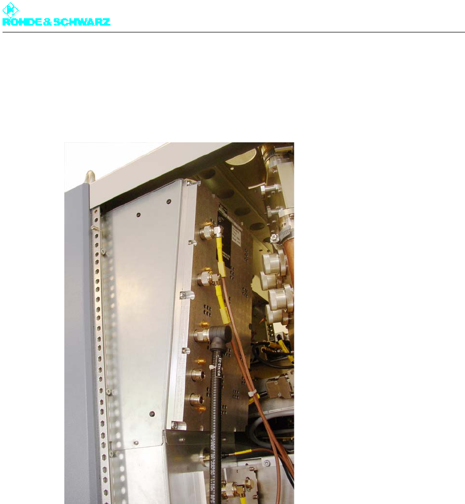
2098.0188.72 - 8.22 - E-1
Fig. 17 Removing exciter switch from transmitter rack
4. Disconnect all cables from the rear of the exciter switch.
5. Undo the fastening screws on the exciter switch.
6. Pull the exciter switch from the transmitter rack.
6.2.2 Installing Exciter Switch
To install the unit in the transmitter, reverse the procedure used to remove it.
1. Connect the cables to the exciter switch according to the labeling (see yellow cable col-
lars).
2. Undo the latch on the guide rails. Simultaneously press the safety lever on the right side
down and on the left side up, and slide the rackmount into the rack.
3. Retighten the captive screws on the front panel of the R&S NetCCU800 and exciter.
Chapter 8 Service
2098.0188.72 - 8.23 - E-1
7 Output Stage Components
You can replace the following output stage components:
Amplifier
Absorber
Note Because of the extremely small probability of failure, replacement of the splitter-combiner
unit will not be described.
7.1 Replacing Amplifiers
When replacing an amplifier from the Rohde & Schwarz transmitters, you do not have to
remove any of the lines since the connections on the rear panel of the device are connected
to the rack using automatic connectors.
7.1.1 Removing Amplifier
1. Switch off the amplifier via the AC distributor in the transmitter rack (turn the the appro-
priate protective switch to the "OFF" position).
Note The other devices in the transmitter rack can remain connected. A transmitter with mul-
tiple amplifiers can remain in operation with reduced power during the exchange of the
amplifier.
2. Undo the four captive screws (Torx screwdriver No. 20) on each side of the front panel.
ATTENTION!
Prior to being removed, the amplifier must be switched free of all voltages in order to pre-
vent any possible damage to the device due to contact consumption.
Chapter 8 Service
2098.0188.72 - 8.24 - E-1
3. Slowly pull the amplifier from the rack using the handles.
The automatic connectors should release on the rear panel of the device.
4. Put the amplifier down with the bottom of the instrument facing downward.
5. If the transmitter is to remain in operation with the remaining amplifiers, close the left and
right vents at the vacant amplifier slot.
7.1.2 Installing Amplifier
To install the unit in the transmitter, reverse the procedure used to remove it.
7.2 Replacing Absorber
7.2.1 Removing Absorber
To remove the absorber proceed as follows:
CAUTION!
Risk of burns on the heat sink. Let the amplifier cool down for about five minutes with the
transmitter cooling switched on before you remove it from the transmitter rack.
CAUTION!
When you pull it out of the transmitter rack, do not allow the amplifier to fall. Support it from
below. The amplifier weighs about 28 kg so we suggest that you use two people to handle
it.
ATTENTION!
To avoid damaging the connectors, do not place the amplifier on its back.
WARNING!
Always make sure that the power supply is disconnected before commencing any service
work on the transmitter rack. This will prevent injury due to electric shock and avoid dam-
age to the instruments.
Chapter 8 Service
2098.0188.72 - 8.25 - E-1
1. Using a Torx screwdriver No. 20, remove the rear panel of the rack.
2. Disconnect the RF connecting cables W1, W2 and W3 to the splitter-combiner unit.
3. Using a Torx screwdriver No. 20 remove all six fixing screws.
4. Pull the absorber unit from the rackmount air outlet duct.
Fig. 18 Removing the absorber
7.2.2 Installing Absorber
To install the unit in the transmitter, reverse the procedure used to remove it.
Chapter 8 Service
2098.0188.72 - 8.26 - E-1
8 Harmonics Filter
In this transmitter family the harmonics filter is built into the RF line.
8.1 Replacing Harmonics Filter
Note The harmonics filter is lacquered in order to reduce the surface temperature, but high tem-
peratures are nevertheless to be expected.
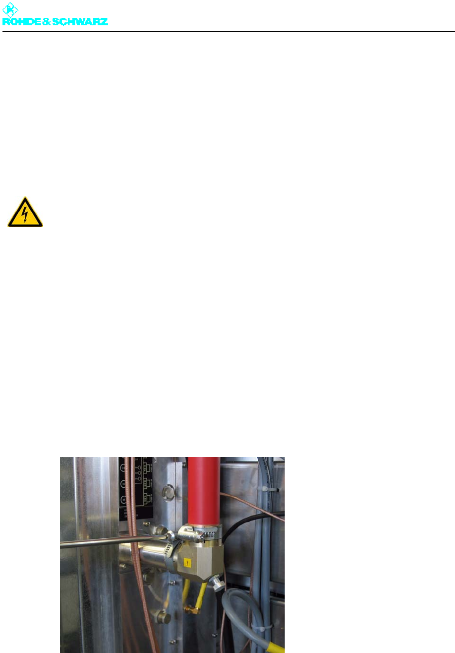
8.1.1 Removing Harmonics Filter
Note The harmonics filter is connected to the RF chain by means of two rigid line brackets. So
that the inner line of the lower rigid line (into the bandpass) stays fixed in place, the tension-
ing clamp of the lower rigid line bracket should be opened first.
To remove the harmonics filter proceed as follows:
1. Open the tensioning clamp of the lower rigid line bracket on the rigid connection of the
combiner.
2. Open the tensioning clamp of the upper rigid line bracket using an open-end wrench
No. 7 or a Phillips screwdriver No. 2.
3. Pull the harmonics filter of the combiner rigid line down and to the right.
4. Pull the harmonics filter downward from the upper rigid line bracket.
WARNING!
Always make sure that the power supply is disconnected before commencing any service
work on the transmitter rack. This will prevent injury due to electric shock and avoid dam-
age to the instruments.
Chapter 8 Service
2098.0188.72 - 8.27 - E-1
Fig. 19 Removing the harmonics filter
8.1.2 Installing Harmonics Filter
The replacement harmonics filter has no rigid line brackets.
Remove the rigid line bracket from the old harmonics filter, attach the bracket to the new
harmonics filter (top) and screw it firmly in place.
To install the unit in the transmitter, reverse the procedure used to remove it.

Chapter 8 Service
2098.0188.72 - 8.28 - E-1
9 Cooling System
You can replace the following cooling system components:
Fan
Starting capacitor
Differential pressure gage
Temperature sensors
9.1 Replacing Fans
The transmitter rack contains two fans as standard; one of these can be reached only from
the front and the other only from the back. However the removal sequence is the same in
both cases.
9.1.1 Removing Fan
Note Prior to removal make sure which of the two fans needs to be replaced.
1. Using a Torx screwdriver No. 20, remove the front panel of the power distribution to re-
place the front fan, or the rear panel of the transmitter to replace the rear fan.
2. Switch off automatic line fuse F6 (rear fan) or F7 (front fan).
Note Wait two minutes before starting to remove the fan (to allow for the fan overrun time).
3. Undo the four screws on the fan housing and remove the cover.
WARNING!
Always make sure that the power supply is disconnected before commencing any service
work on the transmitter rack. This will prevent injury due to electric shock and avoid dam-
age to the instruments.
Chapter 8 Service
2098.0188.72 - 8.29 - E-1
Fig. 20 Undoing the screws from the fan housing
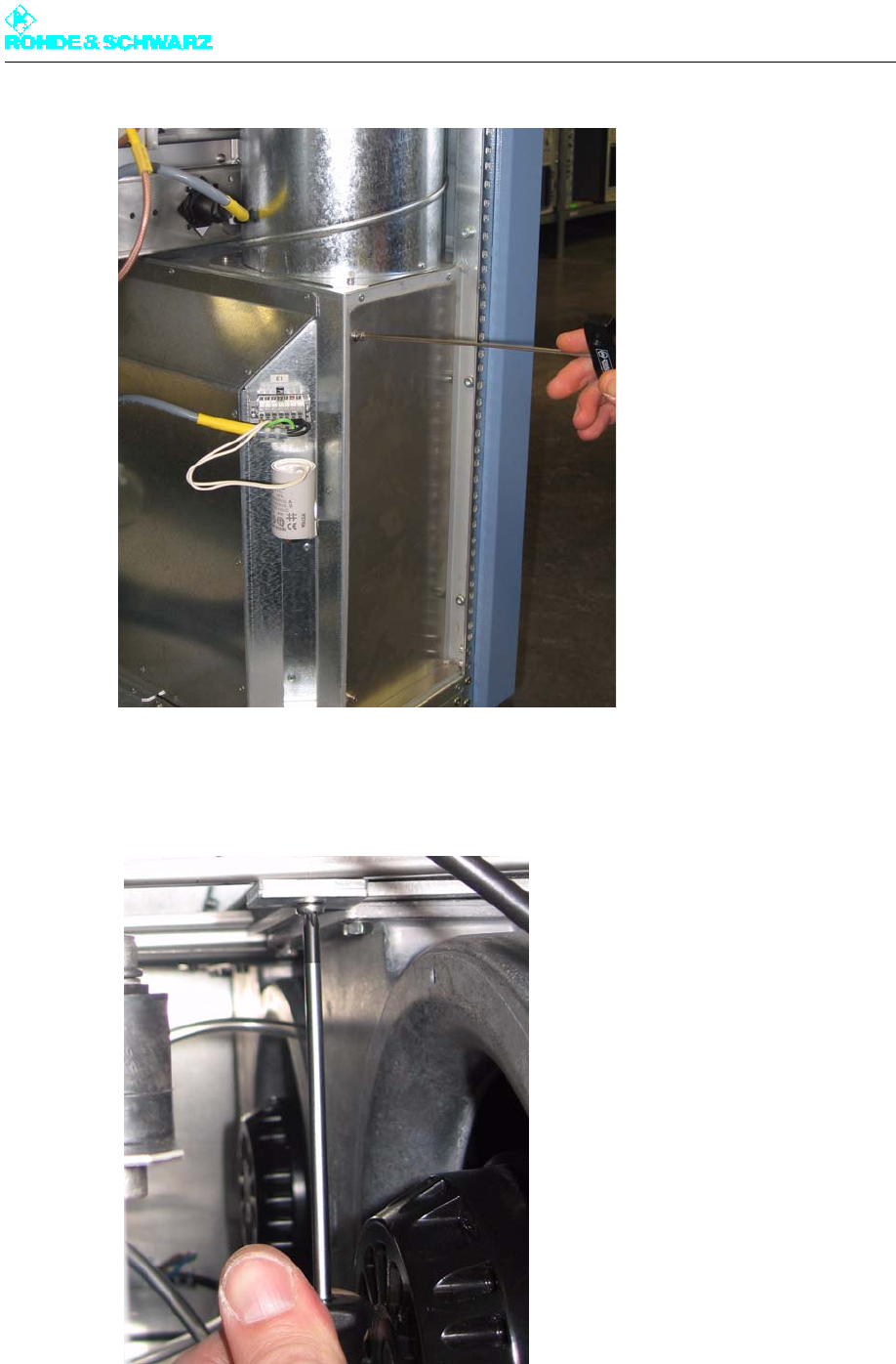
4. On the upper side of the fan housing is a retaining device that must be unscrewed using
a Torx screwdriver No. 20.
Fig. 21 Unscrewing the retaining device
5. Pull the power cable out of the connector and take away the air tube.
Chapter 8 Service
2098.0188.72 - 8.30 - E-1
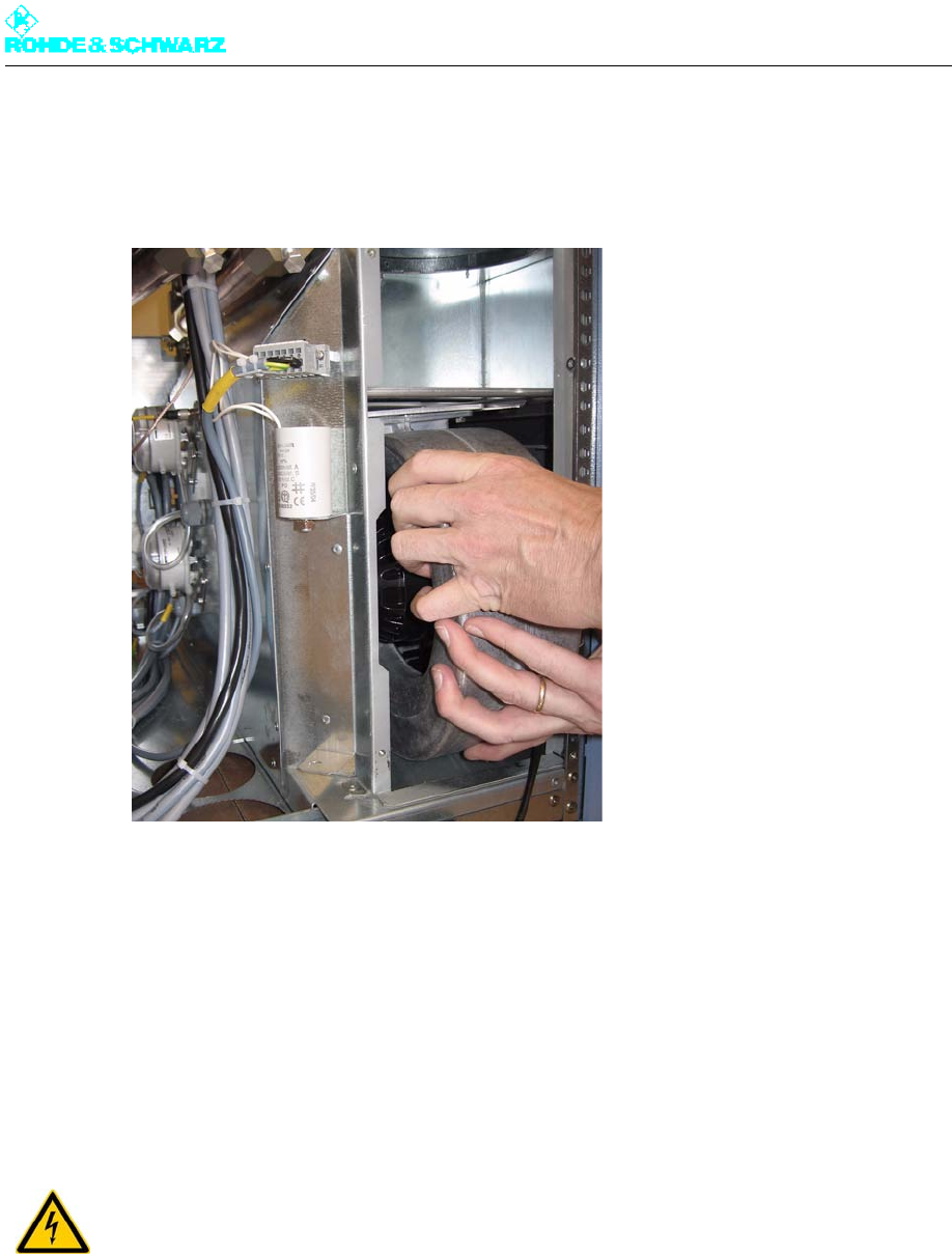
6. Slide the fan slightly to the side, then pull it toward yourself and out of the fan housing.
The fan is easy to remove due to the guide rails
Fig. 22 Removing a fan
9.1.2 Installing Fan
To install the unit in the transmitter, reverse the procedure used to remove it.
9.2 Replacing Starting Capacitors
9.2.1 Removing Starting Capacitor
Note Prior to removal make sure which of the two starting capacitors needs to be replaced.
WARNING!
Always make sure that the power supply is disconnected before commencing any service
work on the transmitter rack. This will prevent injury due to electric shock and avoid dam-
age to the instruments.
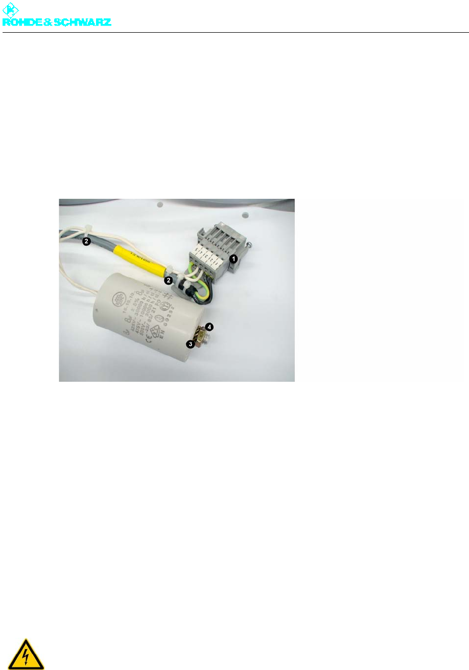
Chapter 8 Service
2098.0188.72 - 8.31 - E-1
1. Using a Torx screwdriver No. 20, remove the front panel of the power distribution to re-
place the front starting capacitor, or the rear panel of the transmitter to replace the rear
starting capacitor.
2. Switch off automatic line fuse F6 (fan 1, rear starting capacitor) or F7 (fan 2, front starting
capacitor).
3. Remove the fan connector.
4. Undo the nut (M8, wrench width 13 mm) on the face plate of the capacitor.
5. Cut off the cable ties to free the cable.
Fig. 23 Removing the starting capacitor
1) Connector (and socket)
2) Cable ties
3) Lock washer
4) Nut (M8)
9.2.2 Installing Starting Capacitor
To install the unit in the transmitter, reverse the procedure used to remove it.
Note The lock washer and M8 nut must be fastened together again.
9.3 Replacing Differential Pressure Gages
WARNING!
Always make sure that the power supply is disconnected before commencing any service
work on the transmitter rack. This will prevent injury due to electric shock and avoid dam-
age to the instruments.
Chapter 8 Service
2098.0188.72 - 8.32 - E-1
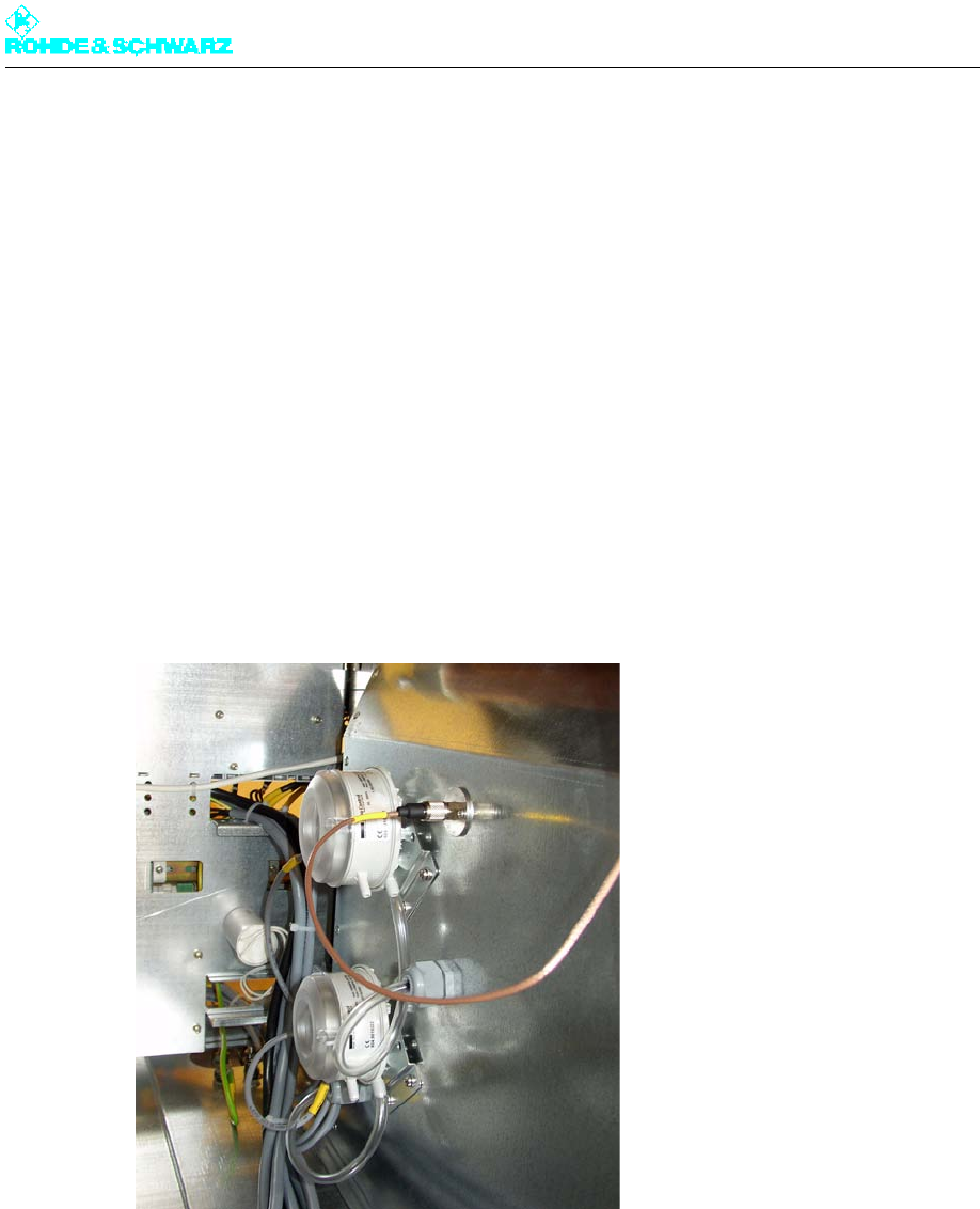
9.3.1 Removing Differential Pressure Gage
Note Prior to removal make sure which of the two differential pressure gages needs to be re-
placed.
1. Using a Torx screwdriver No. 20, remove the rear panel of the rack.
2. Remove the air connector (plastic tube).
3. Disconnect the associated cable from the connector on X45 of the power distribution
board.
(Pins 1 and 2 for differential pressure gage 1, or pins 3 and 4 for differential pressure
gage 2.)
4. Cut off the cable ties to free the cable.
5. Undo the two screws on the bracket.
6. Remove the differential pressure gage.
7. Unscrew the round cover and remove the cable (6.3 mm connector).
Fig. 24 Removing the differential pressure gage
9.3.2 Installing Differential Pressure Gage
To install the unit in the transmitter, reverse the procedure used to remove it.
Check whether the protective cap for the air nozzle on the left-hand differential pressure
gage has already been removed and if not, remove it (see figure).
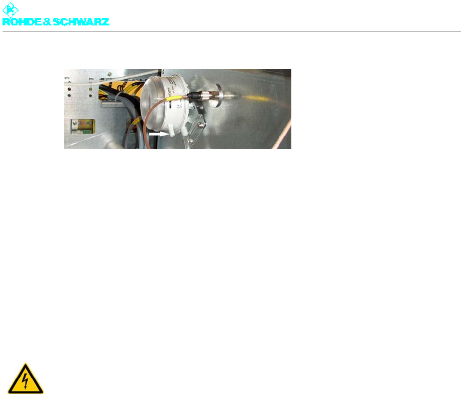
Chapter 8 Service
2098.0188.72 - 8.33 - E-1
Fig. 25 Differential pressure gage without protective cap
Note After installation the differential pressure gage must be set to the switching point of 200 Pa
again.
1. Remove the transparent top cover.
In the middle is an adjuster with a scale.
2. Use a screwdriver to turn the adjuster until the arrow points to the value 200.
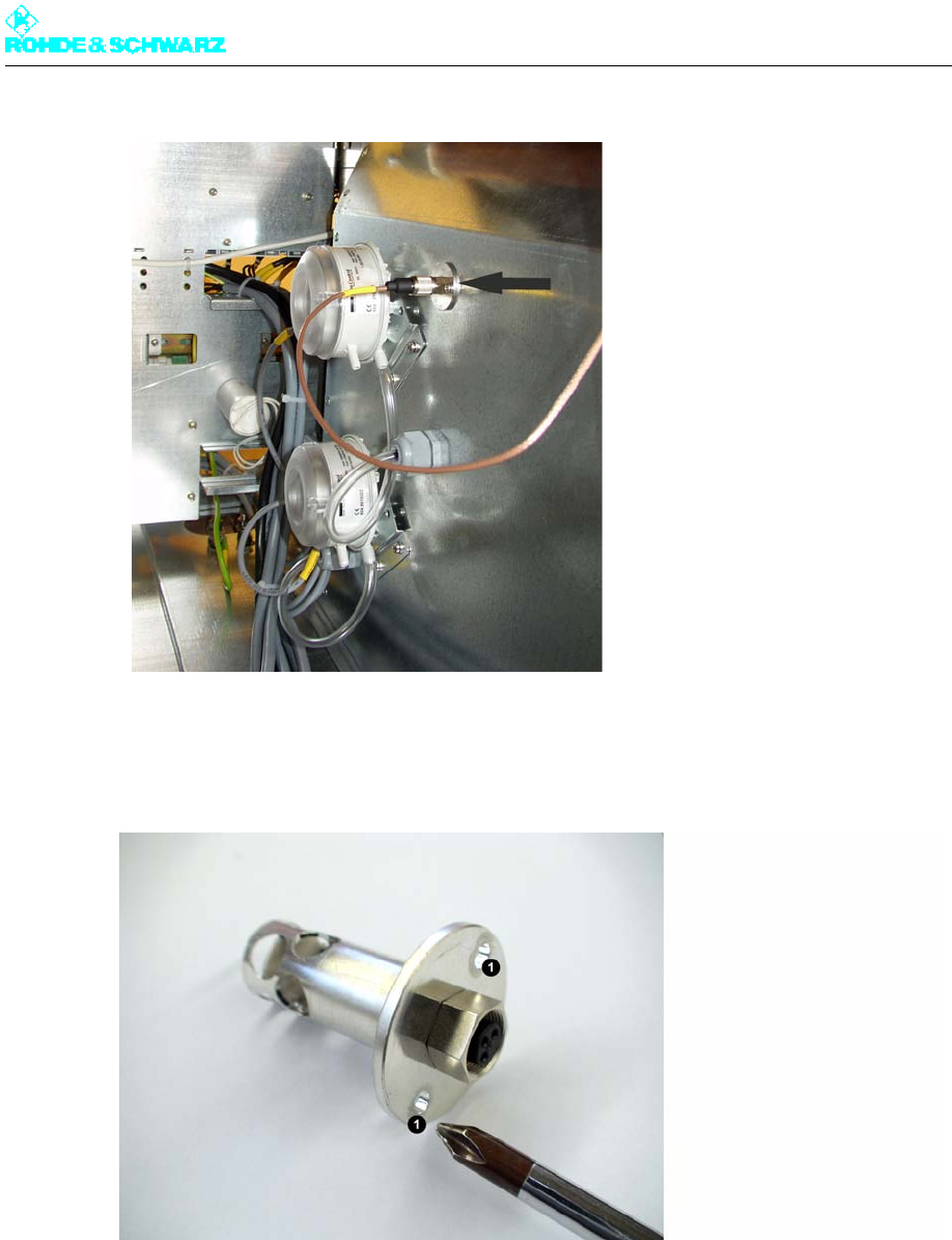
9.4 Replacing Temperature Sensors
The transmitter rack contains two temperatur sensors which measure the intake and outlet
air temperatures. They are located on the intake and outlet lines on the rack.
9.4.1 Removing Temperature Sensor
Note Prior to removal make sure which of the two temperature sensors needs to be replaced.
1. Using a Torx screwdriver No. 20, remove the rear panel of the rack.
2. Unplug the connector of the temperature sensor concerned.
WARNING!
Always make sure that the power supply is disconnected before commencing any service
work on the transmitter rack. This will prevent injury due to electric shock and avoid dam-
age to the instruments.
Chapter 8 Service
2098.0188.72 - 8.34 - E-1
Fig. 26 Removing the temperature sensor
3. Using a Phillips screwdriver No. 0, undo the two screws (M3) on the temperature sensor
flange.
1) Openings for fixing screws (M3)
4. Carefully remove the temperature sensor from the aperture in the air duct.
9.4.2 Installing Temperature Sensor
To install the unit in the transmitter, reverse the procedure used to remove it.

Broadcasting Division
2095.7346.72 - 9.0 - D/E-1
Interface Description
TRANSMITTER
Printed in Germany

Chapter 9 Annex
2098.0188.72 - 9.01 - E-1
CONTENTS
1 Interface Description ....................................................................... 1
1.1 Front-Panel Interfaces ....................................................................................1
1.1.1 Q1 – AC Supply Input / Protective Earth ......................................................1
1.1.2 X57 – Optional Connector Kit ZR800Z1 .......................................................1
1.1.3 X33 – External Fan (Optional): (Wago Plug-In Terminal) .............................1
1.1.4 X34 – AC Power Supply for Control Units and Exciters (Single-Phase):
(Wago Plug-In Terminal) ..............................................................................2
1.1.5 X36 – External Absorber Cooling System (Optional):
(Wago Plug-In Terminal) ..............................................................................2
1.1.6 X41 – RF Carrier Loop: (Wago Plug-In Terminal) ........................................3
1.1.7 X42 – Absorber Monitoring: (Wago Plug-In Terminal) .................................3
1.1.8 X43 – Cooling Monitoring: (Wago Plug-In Terminal) ....................................3
1.1.9 X44 – Overcurrent Monitoring for External Fan: (Wago Plug-In Terminal) ..4
1.2 Interfaces on the Transmitter Top ................................................................4
1.2.1 X100A – Ethernet A Remote (Standard): (8-Contact Female) .....................4
1.2.2 X100B – Ethernet B Remote (N+1 Option): (8-Contact Female) .................5
1.2.3 X232 – RS-232-C: (9-Contact D-Sub Female) .............................................5
1.2.4 X101A – CAN-Bus Rack Bus A: (9-Contact D-Sub Female) ........................6
1.2.5 X101B – CAN-Bus Rack Bus A: (9-Contact D-Sub Female) ........................6
1.2.6 X102A – ANTENNA 1: (N Female, 50 Ohm) ................................................7
1.2.7 X102B – ANTENNA 2: (N Female, 50 Ohm) ................................................7
1.2.8 X121A – TS1 Exciter A: (BNC Female, 75 Ohm) .........................................7
1.2.9 X121B – TS1 Exciter B: (BNC Female, 75 Ohm) .........................................7
1.2.10 X122A – TS2 Exciter A: (BNC Female, 75 Ohm) .........................................8
1.2.11 X122B – TS2 Exciter B: (BNC Female, 75 Ohm) .........................................8
1.2.12 X123A – TS3 Exciter A: (BNC Female, 75 Ohm) .........................................8
1.2.13 X123B – TS3 Exciter B: (BNC Female, 75 Ohm) .........................................8
1.2.14 X124A – TS4 Exciter A: (BNC Female, 75 Ohm) .........................................9
1.2.15 X124B – TS4 Exciter B: (BNC Female, 75 Ohm) .........................................9
1.2.16 X131A – TS1/2 IN Monitoring Exciter A: (BNC Female) ..............................9
1.2.17 X131B – TS1/2 IN Monitoring Exciter B: (BNC Female) ..............................9
1.2.18 X132A – TS3/4 IN Monitoring Exciter A: (BNC Female) ............................10
1.2.19 X132B – TS3/4 IN Monitoring Exciter B: (BNC Female) ............................10
1.2.20 X141A – 1PPS Exciter A: (BNC Female, 50 Ohm) ....................................10

Chapter 9 Annex
2098.0188.72 - 9.02 - E-1
1.2.21 X141B – 1PPS Exciter B: (BNC Female, 50 Ohm) ....................................10
1.2.22 X142A – 1PPS Monitoring Exciter A: (BNC Female, 50 Ohm) ..................11
1.2.23 X142B – 1PPS Monitoring Exciter B: (BNC Female, 50 Ohm) ..................11
1.2.24 X143A – 10 MHz REF.INPUT Exciter A: (BNC Female, 50 Ohm) .............11
1.2.25 X143B – 10 MHz REF.INPUT Exciter B: (BNC Female, 50 Ohm) .............11
1.2.26 RF Transmitter Output (EIA 1 5/8" Flange 50 Ohm ....................................12
1.3 Monitoring Outputs on Front Panel of R&S SV800 Exciter ......................12
1.3.1 X65A – 10 MHz Test Output for Exciter A: (SMA Female, 50 Ohm) ..........12
1.3.2 X65B – 10 MHz Test Output for Exciter B: (SMA Female, 50 Ohm) ..........12
1.3.3 X61A – RF Test Output for Exciter A: (SMA Female, 50 Ohm) .................12
1.3.4 X61B – RF Test Output for Exciter B: (SMA Female, 50 Ohm) .................13
Chapter 9 Annex
2098.0188.72 - 9.1 - E-1
1 Interface Description
1.1 Front-Panel Interfaces
1.1.1 Q1 – AC Supply Input / Protective Earth
1.1.2 X57 – Optional Connector Kit ZR800Z1
1.1.3 X33 – External Fan (Optional): (Wago Plug-In Terminal)
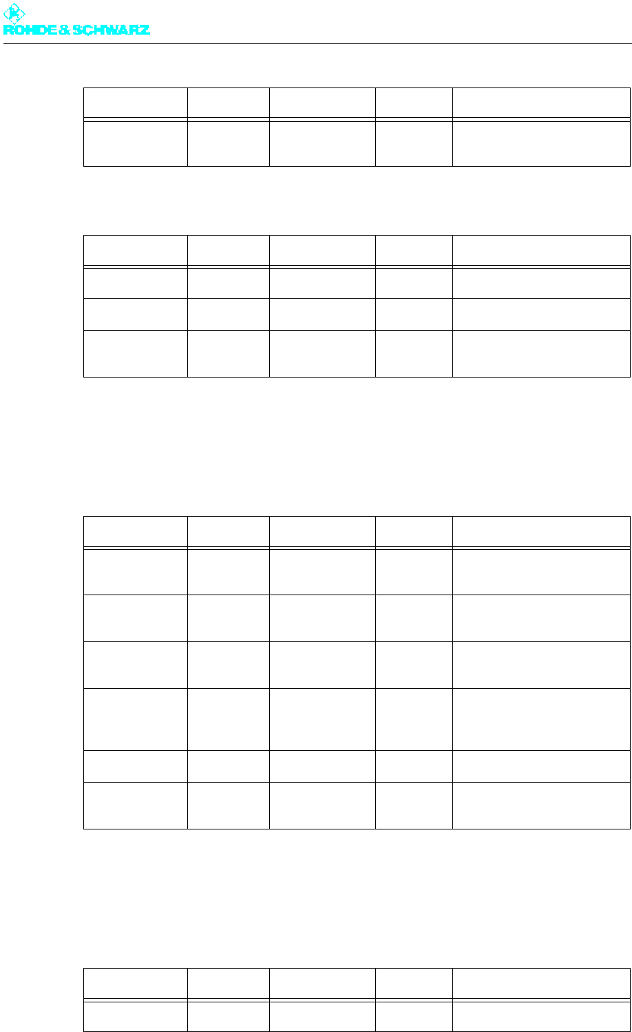
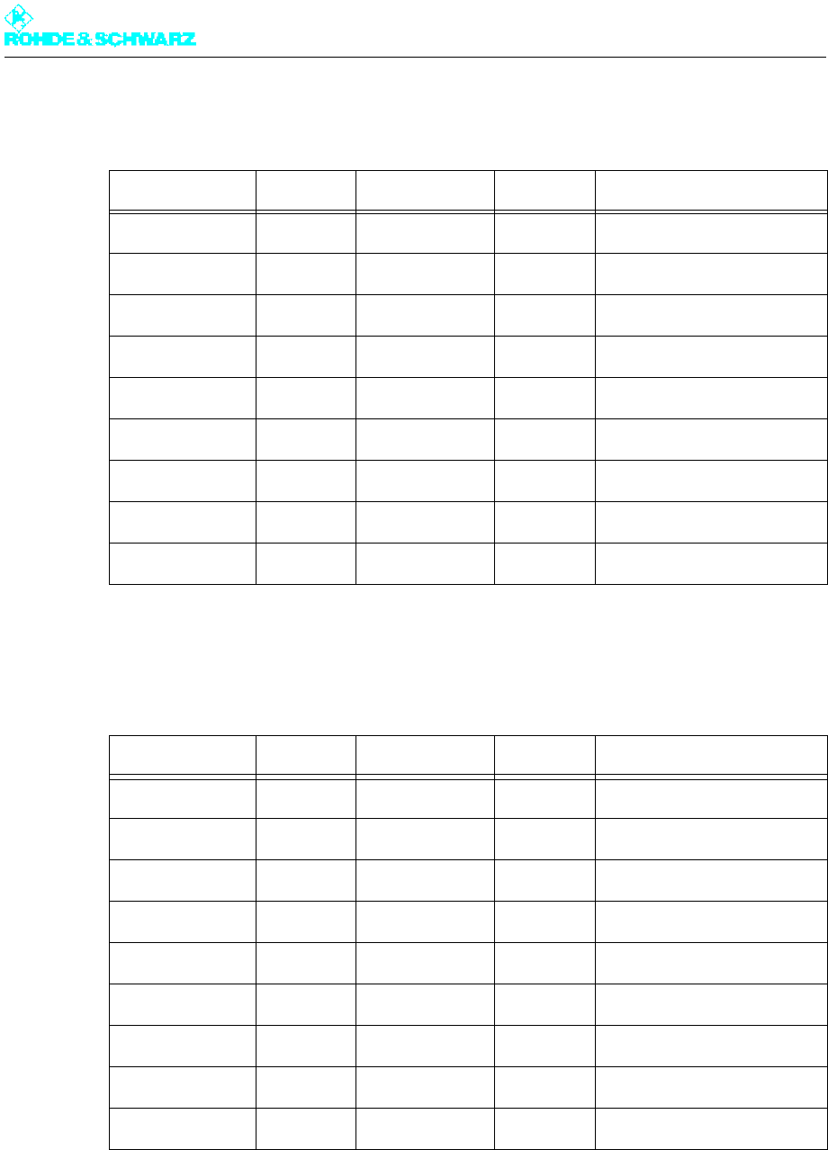
Signal name Direction Value range Contact Remark
PHASE L1 Input 400 V ±15% Q1.T1 Three-phase current input L1
PHASE L2 Input 400 V ±15% Q1.T2 Three-phase current input L2
PHASE L3 Input 400 V ±15% Q1.T3 Three-phase current input L1
NEUTRAL N Input 0 V Q1.N Neutral-conductor input N
PROTECTION
EARTH PE
Input 0 V X.PE PE terminal
PROTECTION
EARTH PE
Input 0 V PE pin PE station
Signal name Direction Value range Contact Remark
PHASE L1 Input 230 V X57.L1 Separate circuit
NEUTRAL N Input 0 V X57.N
PROTECTION
EARTH PE
Input 0 V X57.PE
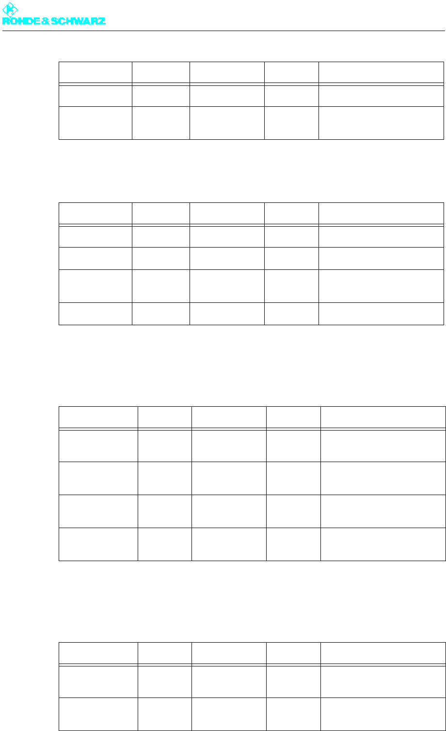
Signal name Direction Value range Contact Remark
PHASE L1 Input 230 V X33.1 Line protection F8 [3A]
NEUTRAL N Input 0 V X33.2
Chapter 9 Annex
2098.0188.72 - 9.2 - E-1
External fan for dummy antenna (optional): (Wago plug-in terminal)
1.1.4 X34 – AC Power Supply for Control Units and Exciters
(Single-Phase): (Wago Plug-In Terminal)
1.1.5 X36 – External Absorber Cooling System (Optional): (Wago
Plug-In Terminal)
PROTECTION
EARTH PE
Input 0 V X33.3
Signal name Direction Value range Contact Remark
PHASE L1 Input 230 V X33.4 Line protection F8 [3A]
NEUTRAL N Input 0 V X33.5
PROTECTION
EARTH PE
Input 0 V X33.6
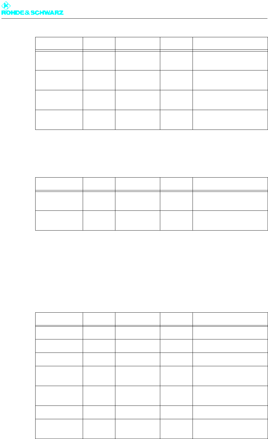
Signal name Direction Value range Contact Remarks
PHASE L1 Output 230 V X34.1 Line fuse F1 [3A]
R&S NetCCU800 connection
PHASE L1 Output 230 V X34.2 Line fuse F2 [3A]
Sx800 A connection
PHASE L1 Output 230 V X34.3 Line fuse F3 [3A]
Sx800 B connection
PHASE L1 Output 230 V X34.4 Line fuse F4 [3A]
Add-on equipment connec-
tion
NEUTRAL N Input 0 V X34.5
PROTECTION
EARTH PE
Input 0 V X34.6
Signal name Direction Value range Contact Remarks
PHASE L3 Output 230 V X36.1 Line fuse F8 [3A]
Signal name Direction Value range Contact Remark
Chapter 9 Annex
2098.0188.72 - 9.3 - E-1
1.1.6 X41 – RF Carrier Loop: (Wago Plug-In Terminal)
1.1.7 X42 – Absorber Monitoring: (Wago Plug-In Terminal)
1.1.8 X43 – Cooling Monitoring: (Wago Plug-In Terminal)
NEUTRAL N Input 0 V X36.2
PROTECTION
EARTH PE
Input 0 V X36.3
Signal name Direction Value range Contact Remark
MAIN TX LOOP Input -12 V ±2 V X41.1 -12 V floating
LOOP COM (+) Output +12 V ±2 V X41.2 +12 V floating
RESERVE TX
LOOP
Input -12 V ±2 V X41.3 -12 V floating
LOOP COM (+) Output +12 V ±2 V X41.4 +12 V floating
Signal name Direction Value range Contact Remark
FAULT SYSTEM
ABSORBER
Input TTL X42.1 Jumper to 0 V
REF RACK
SIGNALS
Output 0 V X42.2 Reference 0 V
FAULT RACK
ABSORBER
Input TTL X42.3 Jumper to 0 V
REF RACK
SIGNALS
Output 0 V X42.4 Reference 0 V
Signal name Direction Value range Contact Remarks
FAULT
COOLING 2
Input TTL X43.1 Jumper against 0 V
REF RACK
SIGNALS
Input 0 V X43.2 Reference 0 V
Signal name Direction Value range Contact Remarks
Chapter 9 Annex
2098.0188.72 - 9.4 - E-1
1.1.9 X44 – Overcurrent Monitoring for External Fan: (Wago Plug-
In Terminal)
1.2 Interfaces on the Transmitter Top
1.2.1 X100A – Ethernet A Remote (Standard): (8-Contact Female)
FAULT
COOLING 1
Input TTL X43.3 Jumper against 0 V
REF RACK
SIGNALS
Input 0 V X43.4 Reference 0 V
WARNING
COOLING
Input TTL X43.5 Jumper against 0 V
REF RACK
SIGNALS
Input 0 V X43.6 Reference 0 V
Signal name Direction Value range Contact Remark
FAULT EXT:
COOLING
Input TTL X44.1 Jumper to 0 V
REF RACK
SIGNALS
Output 0 V X44.4 Reference 0 V
Signal name Direction Value range Contact Remark
TX+ Output Ethernet X100A.1 Transmitting line
TX- Output Ethernet X100A.2 Transmitting line
RX+ Input Ethernet X100A.3 Receiving line
Bidirect. 75 termina-
tion
X100A.4
Bidirect. 75 termina-
tion
X100A.5
RX- Input Ethernet X100A.6 Receiving line
Bidirect. 75 termina-
tion
X100A.7
Signal name Direction Value range Contact Remarks
Chapter 9 Annex
2098.0188.72 - 9.5 - E-1
1.2.2 X100B – Ethernet B Remote (N+1 Option): (8-Contact
Female)
1.2.3 X232 – RS-232-C: (9-Contact D-Sub Female)
Bidirect. 75 termina-
tion
X100A.8
Signal name Direction Value range Contact Remark
TX+ Output Ethernet X100B.1 Transmitting line
TX- Output Ethernet X100B.2 Transmitting line
RX+ Input Ethernet X100B.3 Receiving line
Bidirect. 75 termina-
tion
X100B.4
Bidirect. 75 termina-
tion
X100B.5
RX- Input Ethernet X100B.6 Receiving line
Bidirect. 75 termina-
tion
X100B.7
Bidirect. 75 termina-
tion
X100B.8
Signal name Direction Value range Contact Remark
n.c. X232.1 Transmitting line
RS232_TX Output RS-232 X232.2 Transmitting line
RS232_RX Input RS-232 X232.3 Receiving line
n.c. X232.4
GND Bidirect. X232.5
n.c. X232.6
n.c. X232.7
n.c. X232.8
Signal name Direction Value range Contact Remark
Chapter 9 Annex
2098.0188.72 - 9.6 - E-1
1.2.4 X101A – CAN-Bus Rack Bus A: (9-Contact D-Sub Female)
1.2.5 X101B – CAN-Bus Rack Bus A: (9-Contact D-Sub Female)
Signal name Direction Value range Contact Remark
12V_RED Bidirect. 12 V ±1 V X101A.1 Redundant 12 V supply
RC_A_CAN_L Bidirect. CAN-Level X101A.2 CAN bus signal
CAN_GND Bidirect. 0 V X101A.3 CAN GND
12V_RED Bidirect. 12 V ±1 V X101A.4 Redundant 12 V supply
CAN_SHLD Bidirect. GND X101A.5 Shield
GND Bidirect. GND X101A.6 GND
RC_A_CAN_H Bidirect. CAN+Level X101A.7 CAN bus signal
12V_ASI Bidirect. 12 V ±1.5 V X101A.8
CAN_V+ Bidirect. 12 V ±1 V X101A.9
Signal name Direction Value range Contact Remark
12V_RED Bidirect. 12 V ±1 V X101B.1 Redundant 12 V supply
RC_A_CAN_L Bidirect. CAN-Level X101B.2 CAN bus signal
CAN_GND Bidirect. 0 V X101B.3 CAN GND
12V_RED Bidirect. 12 V ±1 V X101B.4 Redundant 12 V supply
CAN_SHLD Bidirect. GND X101B.5 Shield
GND Bidirect. GND X101B.6 GND
RC_A_CAN_H Bidirect. CAN+Level X101B.7 CAN bus signal
12V_ASI Bidirect. 12 V ±1.5 V X101B.8
CAN_V+ Bidirect. 12 V ±1 V X101B.9
Chapter 9 Annex
2098.0188.72 - 9.7 - E-1
1.2.6 X102A – ANTENNA 1: (N Female, 50 Ohm)
1.2.7 X102B – ANTENNA 2: (N Female, 50 Ohm)
1.2.8 X121A – TS1 Exciter A: (BNC Female, 75 Ohm)
1.2.9 X121B – TS1 Exciter B: (BNC Female, 75 Ohm)
Signal name Direction Value range Contact Remarks
ANTENNA 1 Input > 80 dBV X102A.1 For DVB-T only
Tx level depending on appli-
cation
GND Bidirect. 0 V X102A.2
Signal name Direction Value range Contact Remarks
ANTENNA 2 Input > 80 dBV X102B.1 For DVB-T only
Tx level depending on appli-
cation
GND Bidirect. 0 V X102B.2
Signal name Direction Value range Contact Remark
TS1 Input ASI/SMPTE310M X121A.1 TS1 Exciter A
GND Bidirect. X121A.2 GND/shield
Signal name Direction Value range Contact Remark
TS1 Input ASI/SMPTE310M X121B.1 TS1 Exciter B
GND Bidirect. X121B.2 GND/shield
Chapter 9 Annex
2098.0188.72 - 9.8 - E-1
1.2.10 X122A – TS2 Exciter A: (BNC Female, 75 Ohm)
1.2.11 X122B – TS2 Exciter B: (BNC Female, 75 Ohm)
1.2.12 X123A – TS3 Exciter A: (BNC Female, 75 Ohm)
1.2.13 X123B – TS3 Exciter B: (BNC Female, 75 Ohm)
Signal name Direction Value range Contact Remark
TS2 Input ASI/SMPTE310M X122A.1 TS2 Exciter A
GND Bidirect. X122A.2 GND/shield
Signal name Direction Value range Contact Remark
TS2 Input ASI/SMPTE310M X122B.1 TS2 Exciter B
GND Bidirect. X122B.2 GND/shield
Signal name Direction Value range Contact Remarks
TS3 Input ASI X123A.1 Only for DVB-T with hierar-
chical coding
TS3 Exciter A
GND Bidirect. X123A.2 GND/shield
Signal name Direction Value range Contact Remarks
TS3 Input ASI X123B.1 Only for DVB-T with hierar-
chical coding
TS3 Exciter B
GND Bidirect. X123B.2 GND/shield

Chapter 9 Annex
2098.0188.72 - 9.9 - E-1
1.2.14 X124A – TS4 Exciter A: (BNC Female, 75 Ohm)
1.2.15 X124B – TS4 Exciter B: (BNC Female, 75 Ohm)
1.2.16 X131A – TS1/2 IN Monitoring Exciter A: (BNC Female)
1.2.17 X131B – TS1/2 IN Monitoring Exciter B: (BNC Female)
Signal name Direction Value range Contact Remarks
TS4 Input ASI X124A.1 Only for DVB-T with hierar-
chical coding
TS4 Exciter A
GND Bidirect. X124A.2 GND/shield
Signal name Direction Value range Contact Remarks
TS4 Input ASI X124B.1 Only for DVB-T with hierar-
chical coding
TS4 Exciter B
GND Bidirect. X124B.2 GND/shield
Signal
name Direction Value range Contact Remark
TS1/2 IN
Monitoring
Output ASI/SMPTE310M X131A.1 TS1/2 Monitoring Exciter A
GND Bidirect. X131A.2 GND/shield
Signal
name Direction Value range Contact Remark
TS1/2 IN
Monitoring
Output ASI/SMPTE310M X131B.1 TS1/2 Monitoring Exciter B
GND Bidirect. X131B.2 GND/shield

Chapter 9 Annex
2098.0188.72 - 9.10 - E-1
1.2.18 X132A – TS3/4 IN Monitoring Exciter A: (BNC Female)
1.2.19 X132B – TS3/4 IN Monitoring Exciter B: (BNC Female)
1.2.20 X141A – 1PPS Exciter A: (BNC Female, 50 Ohm)
1.2.21 X141B – 1PPS Exciter B: (BNC Female, 50 Ohm)
Signal
name Direction Value range Contact Remarks
TS3/4 IN
Monitoring
Output ASI X132A.1 Only for DVB-T with hierar-
chical coding
TS3/4 Monitoring Exciter A
GND Bidirect. X132A.2 GND/shield
Signal
name Direction Value range Contact Remarks
TS3/4 IN
Monitoring
Output ASI X132B.1 Only for DVB-T with hierar-
chical coding
TS3/4 monitoring Exciter B
GND Bidirect. X132B.2 GND/shield
Signal name Direction Value range Contact Remarks
1PPS_EXTERN Input TTL level
(pos.edge)
X141A.1 Second pulse from external
GPS receiver (exciter A)
GND Bidirect. X141A.2 GND/shield
Signal name Direction Value range Contact Remarks
1PPS_EXTERN Input TTL level
(pos.edge)
X141B.1 Second pulse from external
GPS receiver (exciter B)
GND Bidirect. X141B.2 GND/shield
Chapter 9 Annex
2098.0188.72 - 9.11 - E-1
1.2.22 X142A – 1PPS Monitoring Exciter A: (BNC Female, 50 Ohm)
1.2.23 X142B – 1PPS Monitoring Exciter B: (BNC Female, 50 Ohm)
1.2.24 X143A – 10 MHz REF.INPUT Exciter A: (BNC Female,
50 Ohm)
1.2.25 X143B – 10 MHz REF.INPUT Exciter B: (BNC Female,
50 Ohm)
Signal name Direction Value range Contact Remarks
1PPS Monitor-
ing
Output TTL level
(pos.edge)
X142A.1 Monitor output of internally
used 1PPS (exciter A)
GND Bidirect. X142A.2 GND/shield
Signal name Direction Value range Contact Remarks
1PPS Monitor-
ing
Output TTL level
(pos.edge)
X142B.1 Monitor output of internally
used 1PPS (exciter B)
GND Bidirect. X142B.2 GND/shield
Signal name Direction Value range Contact Remark
10 MHz REF
INPUT
Input -5.0 dB to 20 dBm
or TTL
X143A.1 10 MHz reference for
exciter A
GND Bidirect. X142A.2 GND/shield
Signal name Direction Value range Contact Remark
10 MHz REF
INPUT
Input -5.0 dB to 20 dBm
or TTL
X143B.1 10 MHz reference for
exciter B
GND Bidirect. X142B.2 GND/shield
Chapter 9 Annex
2098.0188.72 - 9.12 - E-1
1.2.26 RF Transmitter Output (EIA 1 5/8" Flange 50 Ohm
1.3 Monitoring Outputs on Front Panel of R&S SV800
Exciter
1.3.1 X65A – 10 MHz Test Output for Exciter A: (SMA Female,
50 Ohm)
1.3.2 X65B – 10 MHz Test Output for Exciter B: (SMA Female,
50 Ohm)
1.3.3 X61A – RF Test Output for Exciter A: (SMA Female, 50 Ohm)
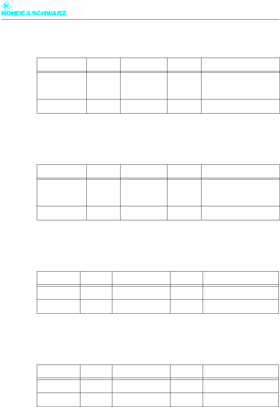
Signal name Direction Value range Contact Remark
RF transmitter
output
Output PmaxAVG = 1.8 kW RF RF transmitter output, fully
equipped with 4 amplifiers
GND Bidirect. RF GND/shield
Signal name Direction Value range Contact Remarks
10MHz_REF_
OUT
Output 0 dBm
(+2 dB to -1 dB)
X65A.1 10MHz reference monitor-
ing for exciter A
GND Bidirect. X65A.2 GND/shield
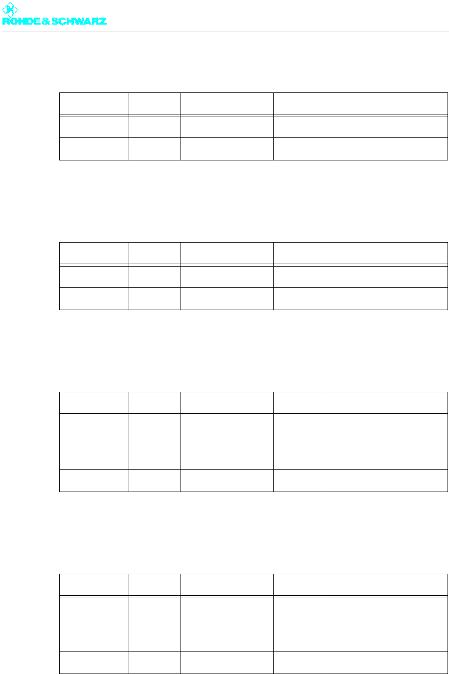
Signal name Direction Value range Contact Remarks
10MHz_REF_
OUT
Output 0 dBm
(+2 dB to -1 dB)
X65B.1 10MHz reference monitor-
ing for exciter B
GND Bidirect. X65B.2 GND/shield
Signal name Direction Value range Contact Remarks
RF_MONOUT Output -7dBm ±2dB X61A.1 RF OUT monitoring for
exciter A

Chapter 9 Annex
2098.0188.72 - 9.13 - E-1
1.3.4 X61B – RF Test Output for Exciter B: (SMA Female, 50 Ohm)
GND Bidirect. X61A.2 GND/shield
Signal name Direction Value range Contact Remarks
RF_MONOUT Output -7dBm ±2dB X61B.1 RF OUT monitoring for
exciter B
GND Bidirect. X61B.2 GND/shield
Signal name Direction Value range Contact Remarks

Chapter 9 Annex
2098.0188.72 - 9.14 - E-1

Broadcasting Division
2098.7346.72 - 10.0 - E-1
DATA SHEETS
Printed in Germany

Broadcasting Division
2098.0188.72 -01 - 2.1 -
System Manual
Volume 2
R&S®NV830x
DTV Transmitter ATSC
Transmitter Series Nx8000
Only skilled personnel may perform the operations of the described instrument that
are necessary for installing and putting it into operation as well as maintaining, trou-
bleshooting and servicing it.
Printed in Germany

System Manual
Transmitter Series Nx8000
Edition: August 2009
Version: E 01.00
2098.0188.72 -01- 2.2 -
© 2009 Rohde&Schwarz GmbH & Co. KG
81671 Munich, Germany
This document may be duplicated or otherwise used or its contents made known to third parties only with
permission of the originator or other authorized persons.
Infringements constitute an offence and are subject to claim for damages (UrhG, UWG, BGB).
All rights reserved for patenting or utility model registration.
The R&S logo, Rohde & Schwarz and R&S are registered trademarks
of Rohde & Schwarz GmbH & Co.KG and their subsidiaries.
ROHDE & SCHWARZ GmbH & Co.KG
D-81671 München - Mühldorfstraße 15
Telefon: (089) 4129-0 ^ Int. +49894129-0
Telefax: (089) 4129-12164
Internet: www.rohde-schwarz.com
Printed in Federal Republic of Germany ^ Subject to change ^ Data without tolerances: typical values

2098.0188.72 - 2.3 - E-1
NV830XE/V CONTENTS
DRAWINGS AND DIAGRAMS NV8301 1
DRAWINGS AND DIAGRAMS NV8302 2
DRAWINGS AND DIAGRAMS NV8303 3
DRAWINGS AND DIAGRAMS NV8304 4
SPARE PARTS LISTS 5
6
7
8
9

Broadcasting Division
2098.0188.72 - 1 - E-1
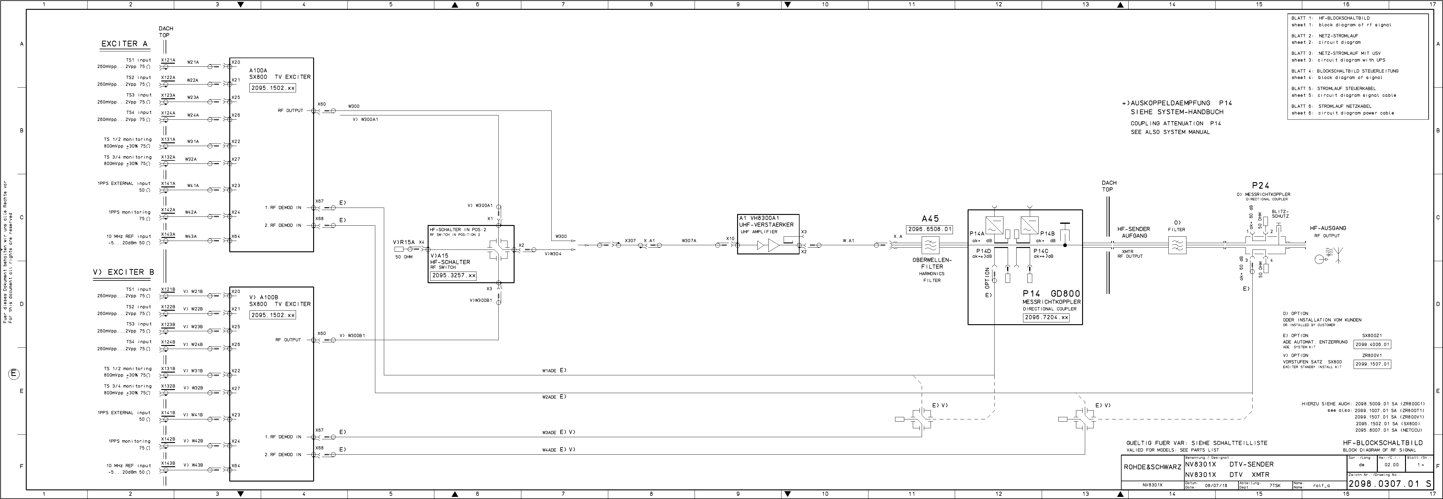
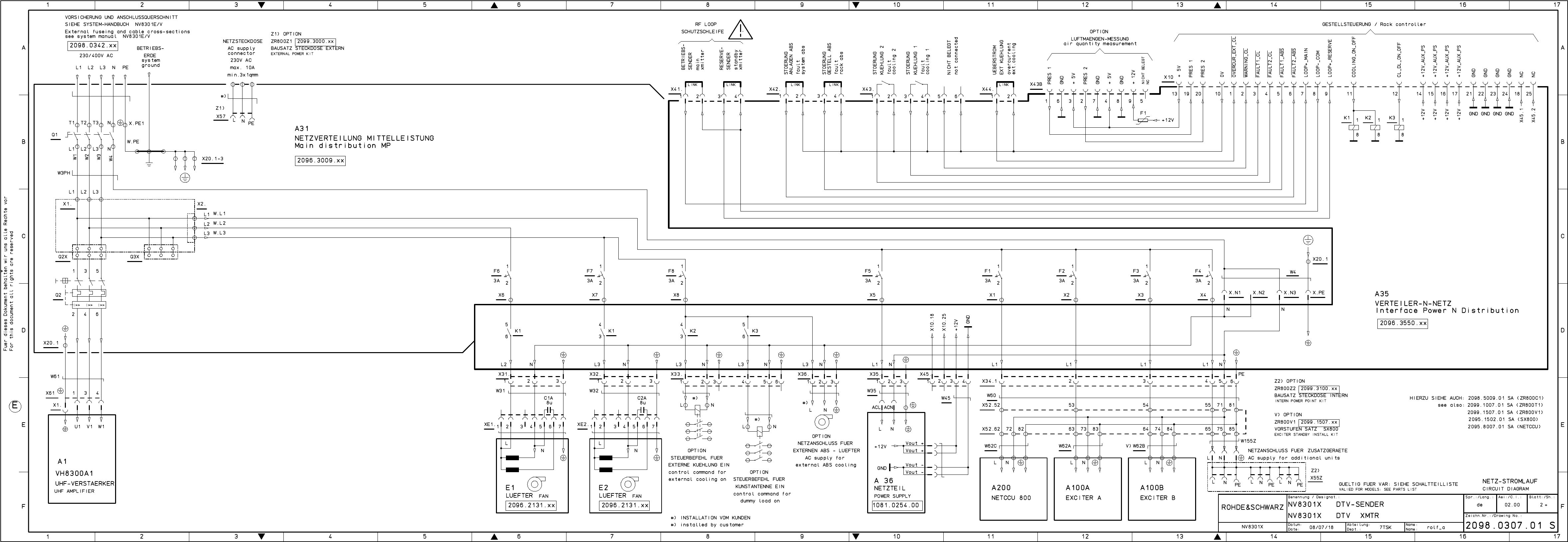
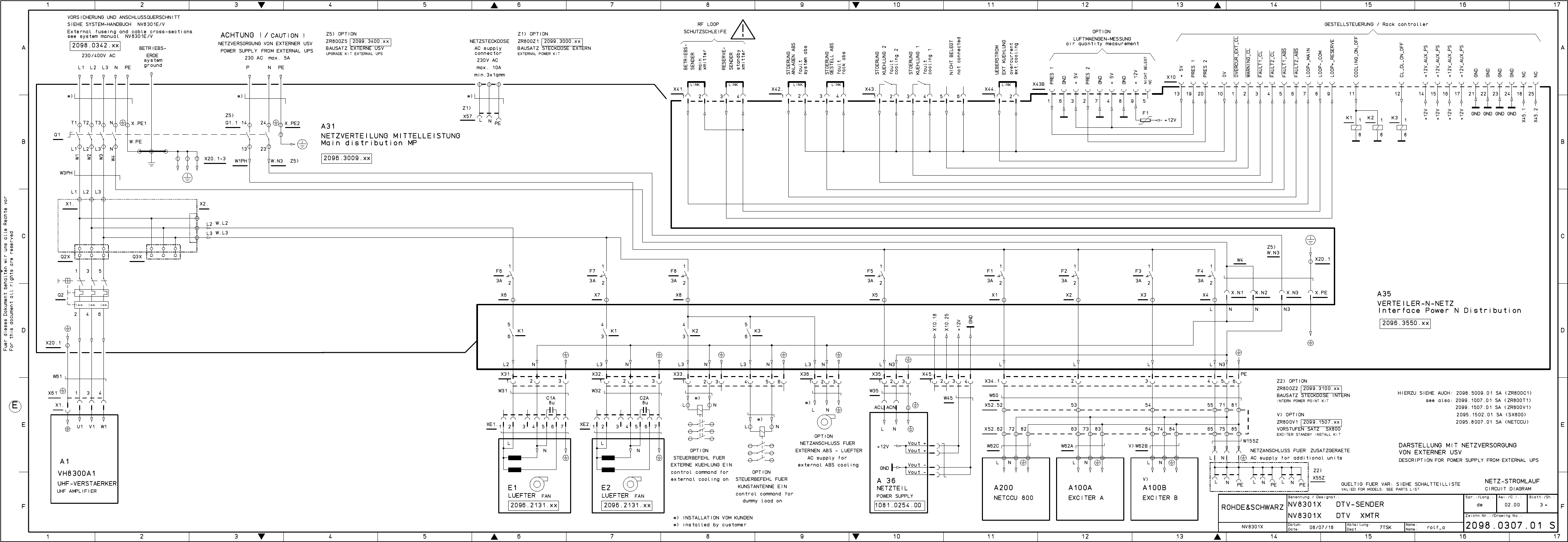
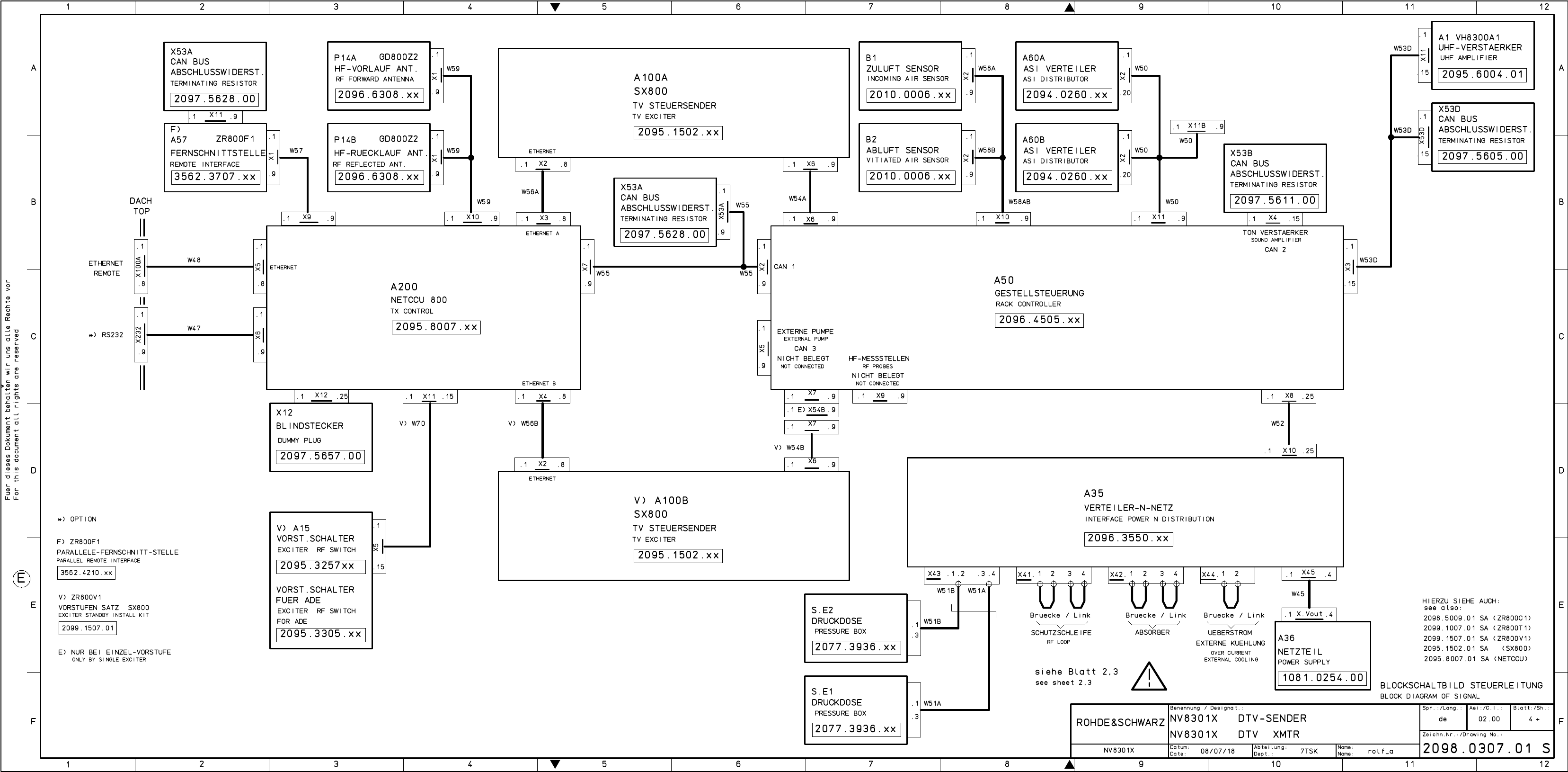
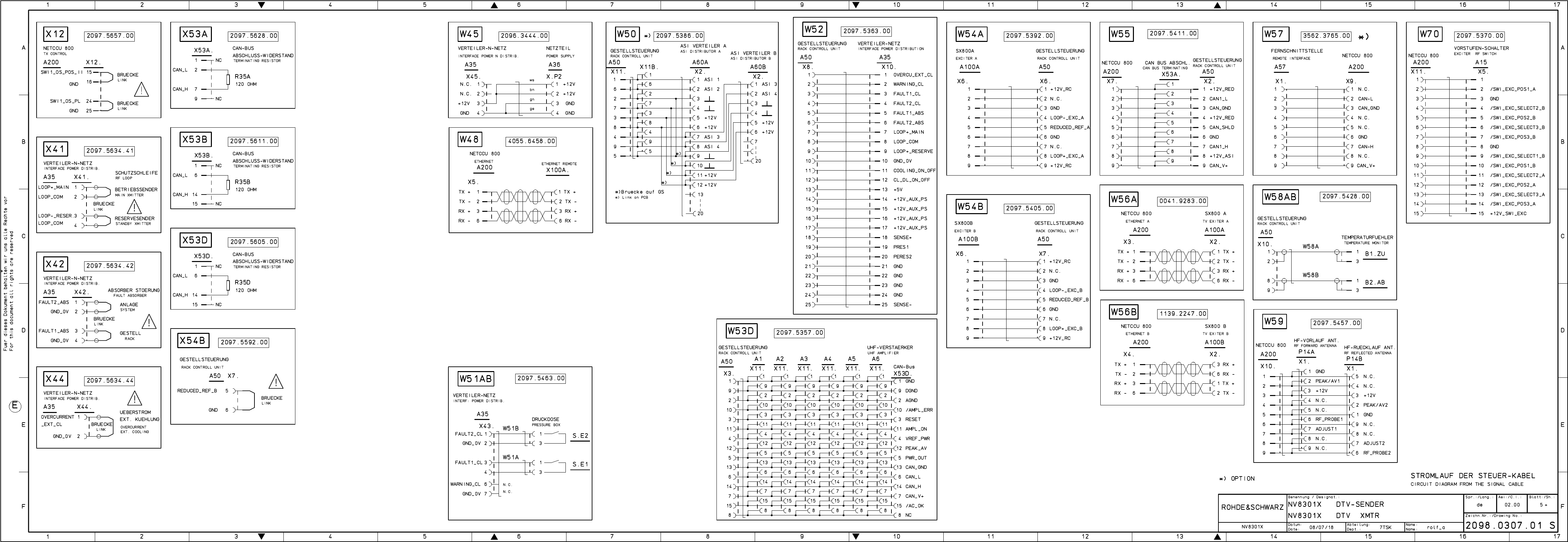
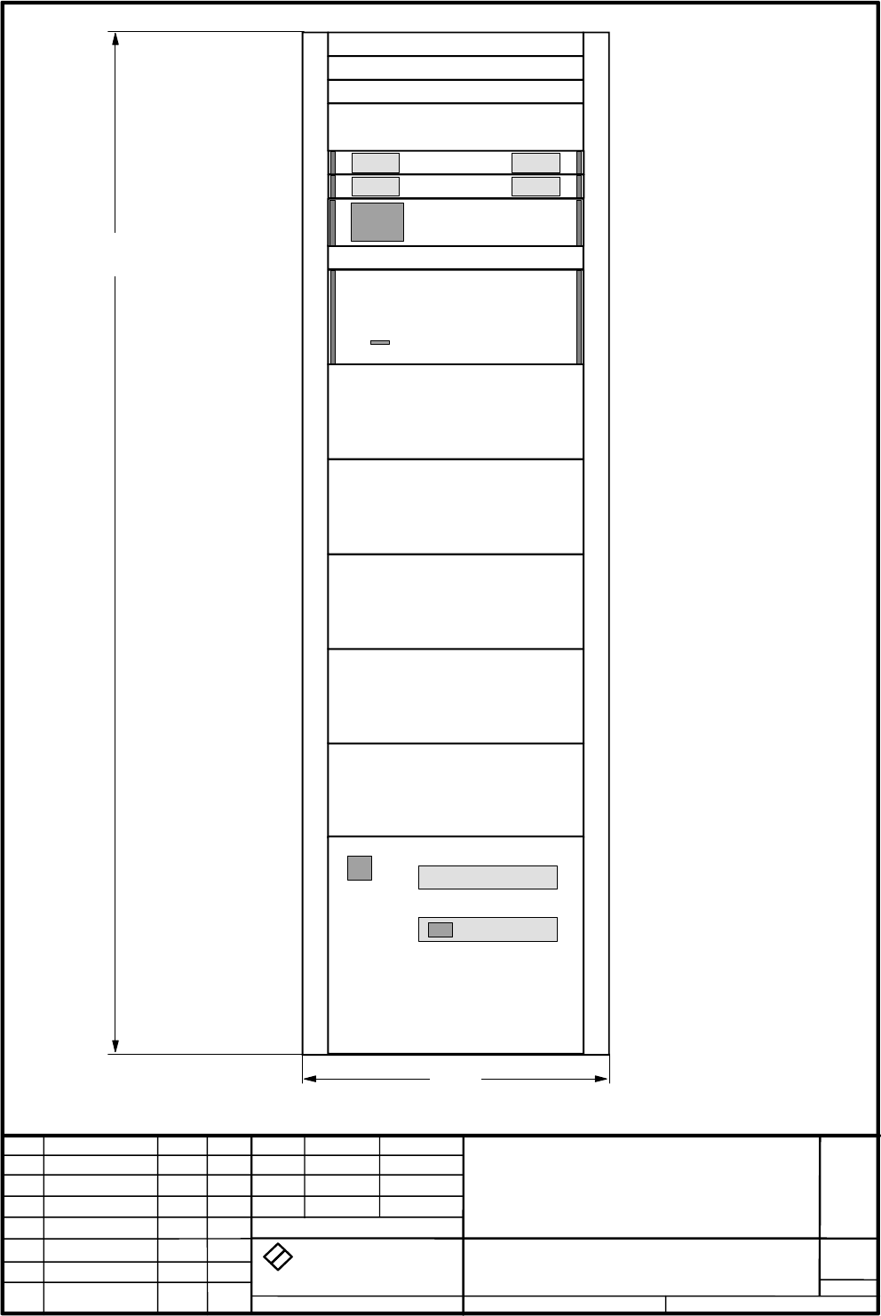
Drawings and Diagrams
NV8301E/V
2098.0307.01
Printed in Germany


Für diese Unterlage behalten wir uns alle Rechte vor.
Ausgedruckte Dokumente unterliegen nicht dem Änderungsdienst.
For this document all rights are reserved.
Printed documents are not subject to revision
_
el.Kennz
Part Benennung / Hinweise
Designation Sachnummer
Stock No. Hersteller
Manufacturer Bestellbezeichnung
Designation enthalten in
contained in
a
Benennung/Designation
NV8301X DTV-SENDER
NV8301X DTV XMTR
Sprach./Lang
de en Ä.I. / C.I
01.00 Blatt/Sheet
1 of 1
Dokument Nr. / Document No.
2098.0307.01 SA
NV8301X Datum/
Date 2008-01-17 Abt. /
Dept. 7TSK Name /
Name Ro
ACHTUNG EGB /ATTENTION ESD
*VARIANTENERKLAERUNG
*EXPLANATION OF MODELS
VAR04=NV8301E DTV-SENDER MIT
EINZEL-VORSTUFE
PROGNOSESENDER
MOD04=NV8301E DTV-
TRANSMITTER WITH SINGLE
EXCITER
VAR24=NV8301V DTV-SENDER MIT
VORSTUFE-RESERVE OHNE ADE
PROGNOSESENDER
MOD24=NV8301V DTV
TRANSMITTER WITH DUAL DRIVE
WITHOUT ADE
VAR50=NV8301X DTV-SENDER
+++GRUNDSENDER+++
MOD50=NV8301X DTV-
TRANSMITTER ++BASIC
TRANSMITTER++
A1 GG VH8300A1 UHF-VERSTAER. 3-
Phasig
2095.6004.02 2098.0307.01
VH8300A1 UHF-AMPLIFIER
VAR 04 24
A20 GS ZR800T1 EINBAUS. SX800 2099.1007.03 2098.0307.01
ZR800T1 INSTAL. KIT
VAR 04 24
DTV - Ausfuehrung
A21 GS ZR800C1 LEISTUNGSSATZ 2098.5009.41 2098.0307.01
ZR800C1 POWER KIT
VAR 04 24
Leistungssatz fuer 1 Verstaerker
A23 GS ZR800V1 VORST.SA SX800 2099.1507.04 2098.0307.01
ZR800V1 EXC.INST. KIT
VAR 24
Vorstufensatz - DTV ohne ADE
A200 GG NETCCU 800 CONTROL UNIT 2095.8007.02 2098.0307.01
NETCCU 800 CONTROL UNIT
VAR 04 24
A100A GG SX800 TV EXCITER DTV UND
ADE INT RF
2095.1502.71 2098.0307.01
SX800 TV EXCITER
VAR 04 24
A100B GG SX800 TV EXCITER DTV UND
ADE INT RF
2095.1502.71 2098.0307.01
SX800 TV EXCITER
VAR 24
DTV-TA NSMITTER BD.IV/V
R
S
7TSK
2098.0307 V
1
2098.0307.01
Benennung
Zeichn.-Nr.
Änderungs-
Mitteilung
Tag
Name
Bearb.
Gepr.
Norm
Änd.
Zust.
Tag
Name
zu Gerät
reg. i. V.
erste Z.
Blatt-Nr.
v. Bl.
ROHDE & SCHWARZ
RO
0000.0000.00
D
1
NV8301x
DTV-Sender Bd.IV/V
01.08
NV8301x
S\DESI-DAT\NV8300\NV8301x
01.00 01.08 RO
#)
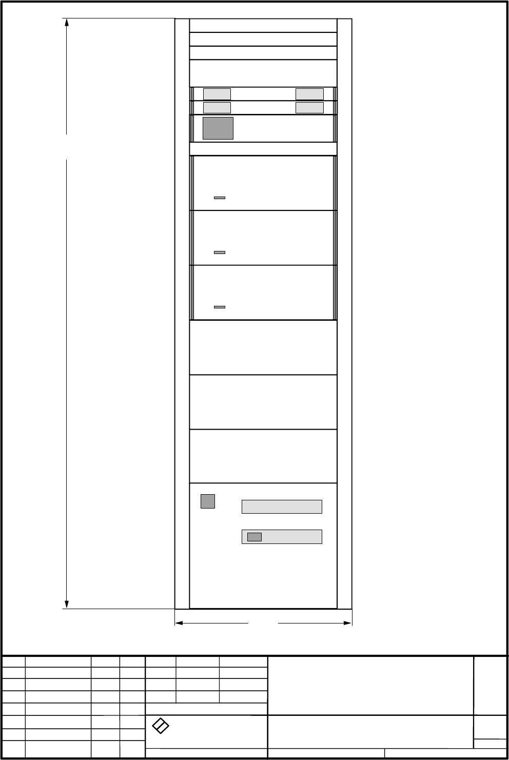
OPTION Variantenerklärung siehe Schaltteilliste
Valid for model see parts list
Tiefe: 800
Depth: 800
A200
A1
A100A
A100B
#)
ROHDE & SCHWARZ
2000
600

Broadcasting Division
2098.0188.72 - 2 - E-1
Drawings and Diagrams
NV8302E/V
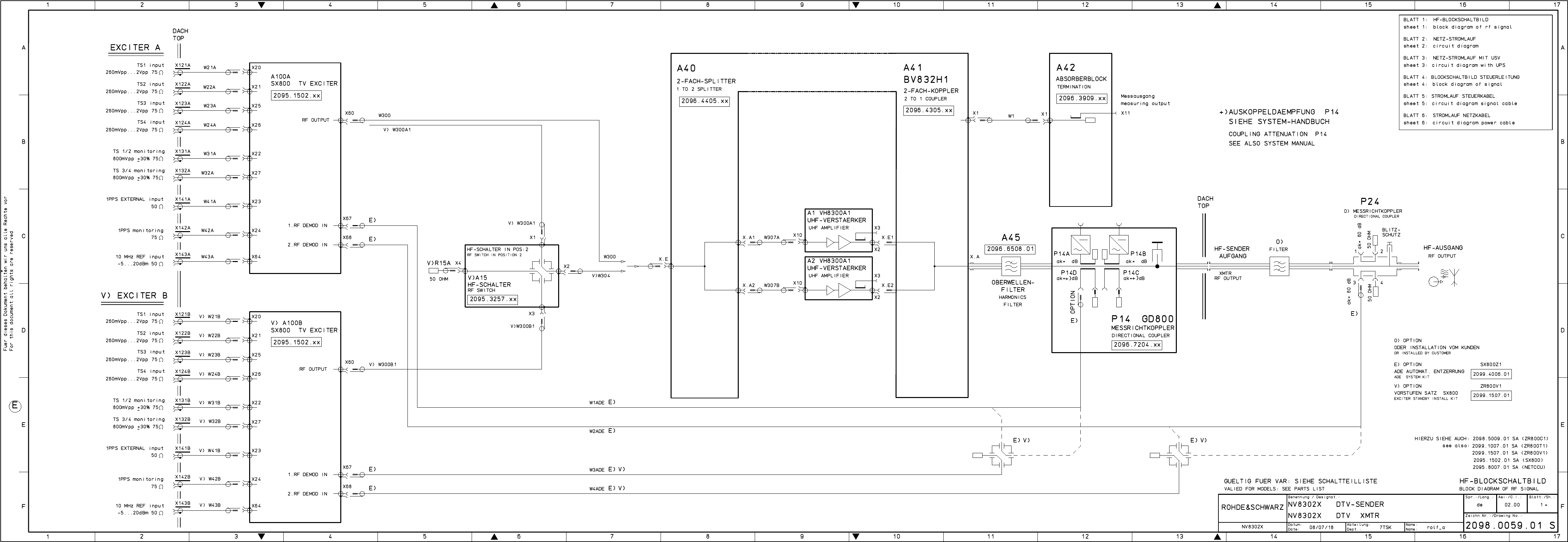
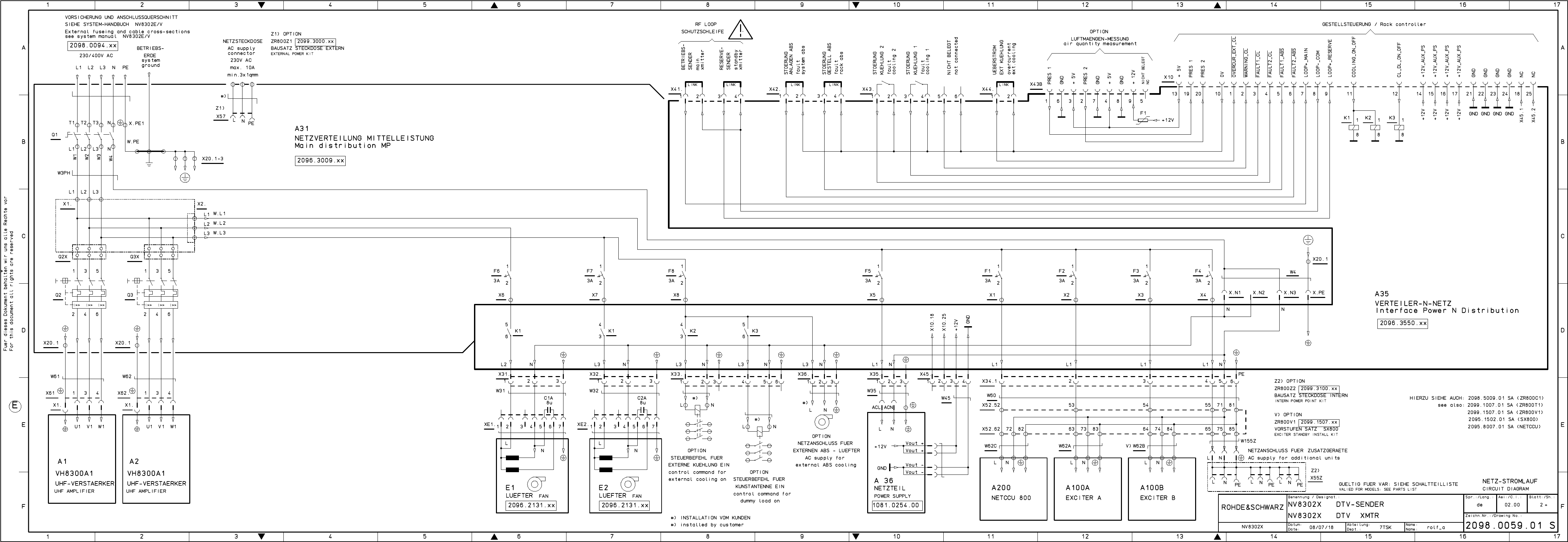
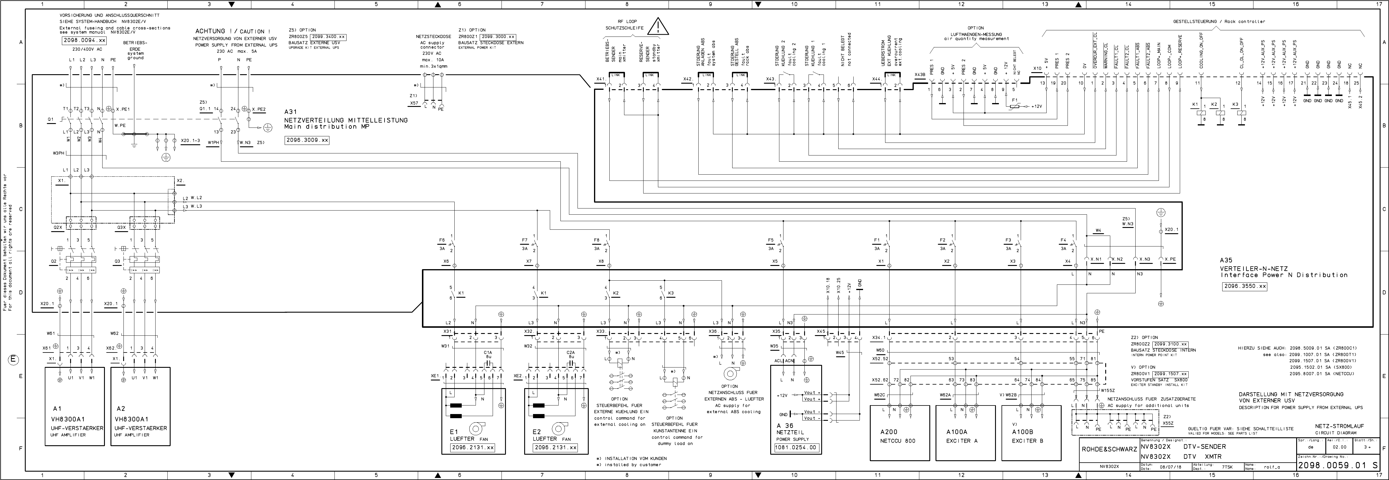
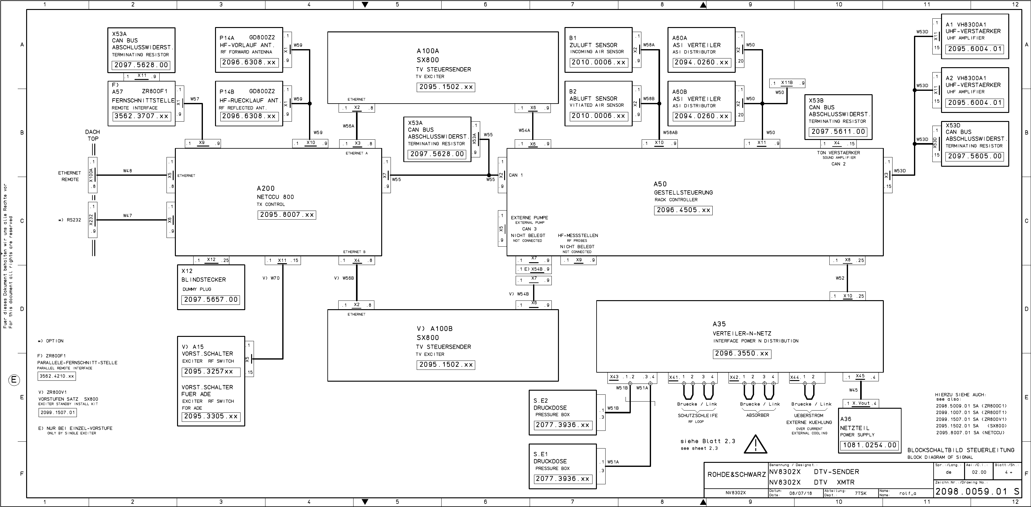
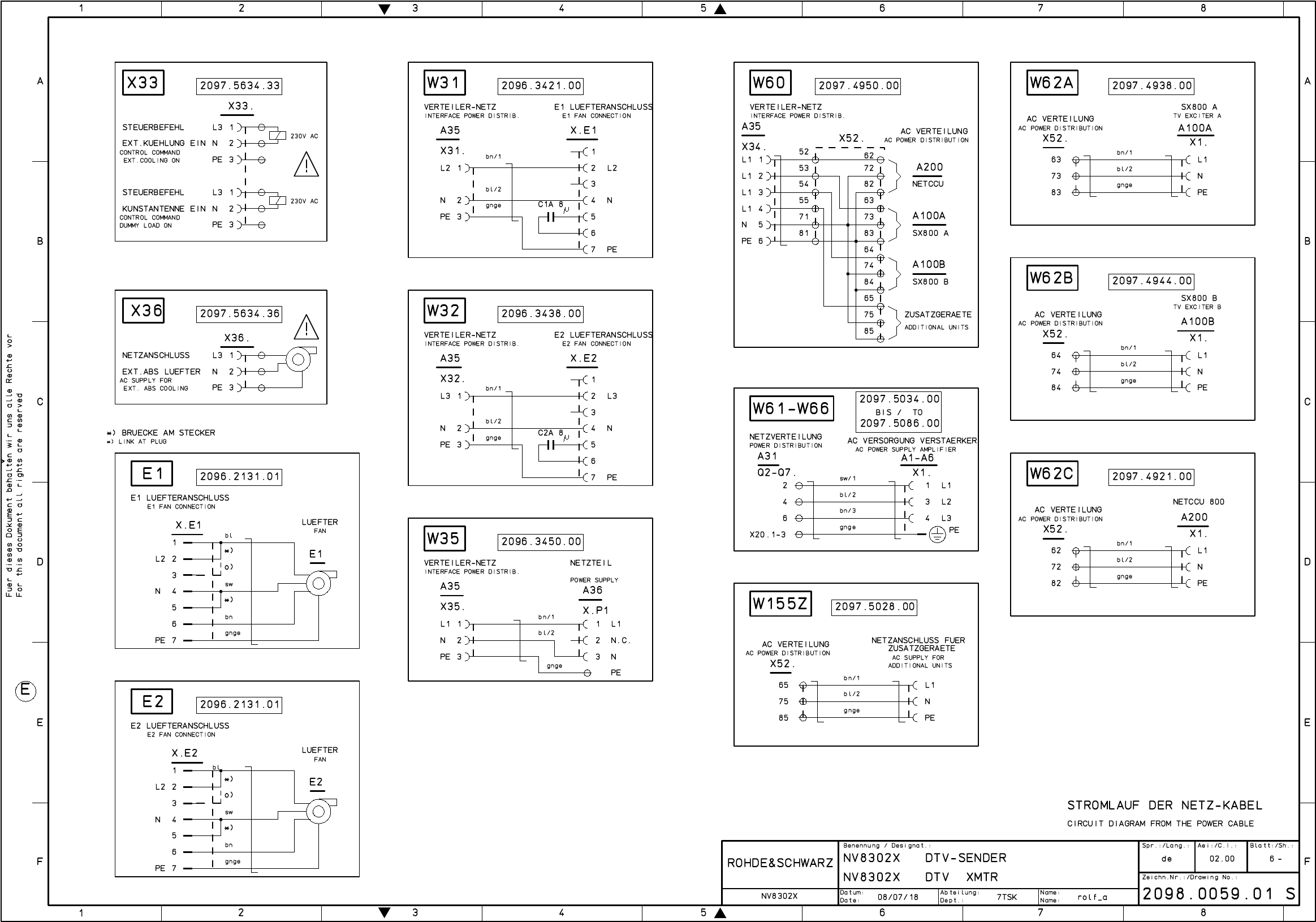
2098.0059.01
Printed in Germany

Für diese Unterlage behalten wir uns alle Rechte vor.
Ausgedruckte Dokumente unterliegen nicht dem Änderungsdienst.
For this document all rights are reserved.
Printed documents are not subject to revision
_
el.Kennz
Part Benennung / Hinweise
Designation Sachnummer
Stock No. Hersteller
Manufacturer Bestellbezeichnung
Designation enthalten in
contained in
a
Benennung/Designation
NV8302X DTV-SENDER
NV8302X DTV XMTR
Sprach./Lang
de en Ä.I. / C.I
01.00 Blatt/Sheet
1 of 1
Dokument Nr. / Document No.
2098.0059.01 SA
NV8302X Datum/
Date 2008-01-17 Abt. /
Dept. 7TSK Name /
Name Ro
ACHTUNG EGB /ATTENTION ESD
*VARIANTENERKLAERUNG
*EXPLANATION OF MODELS
VAR04=NV8302E DTV-SENDER MIT
EINZEL-VORSTUFE
PROGNOSESENDER
MOD04=NV8302E DTV-
TRANSMITTER WITH SINGLE
EXCITER
VAR24=NV8302V DTV-SENDER MIT
VORSTUFE-RESERVE OHNE ADE
PROGNOSESENDER
MOD24=NV8302V DTV
TRANSMITTER WITH DUAL DRIVE
WITHOUT ADE
VAR50=NV8302X DTV-SENDER
+++GRUNDSENDER+++
MOD50=NV8302X DTV-
TRANSMITTER ++BASIC
TRANSMITTER++
A1 - A2 GG VH8300A1 UHF-VERSTAER. 3-
Phasig
2095.6004.02 2098.0059.01
VH8300A1 UHF-AMPLIFIER
VAR 04 24
A20 GS ZR800T1 EINBAUS. SX800 2099.1007.03 2098.0059.01
ZR800T1 INSTAL. KIT
VAR 04 24
DTV - Ausfuehrung
A21 GS ZR800C1 LEISTUNGSSATZ 2098.5009.42 2098.0059.01
ZR800C1 POWER KIT
VAR 04 24
Leistungssatz fuer 2 Verstaerker
A23 GS ZR800V1 VORST.SA SX800 2099.1507.04 2098.0059.01
ZR800V1 EXC.INST. KIT
VAR 24
Vorstufensatz - DTV ohne ADE
A200 GG NETCCU 800 CONTROL UNIT 2095.8007.02 2098.0059.01
NETCCU 800 CONTROL UNIT
VAR 04 24
A100A GG SX800 TV EXCITER DTV UND
ADE INT RF
2095.1502.71 2098.0059.01
SX800 TV EXCITER
VAR 04 24
A100B GG SX800 TV EXCITER DTV UND
ADE INT RF
2095.1502.71 2098.0059.01
SX800 TV EXCITER
VAR 24
DTV-TA NSMITTER BD.IV/V
R
S
7TSK
2098.0059 V
1
2098.0059.01
Benennung
Zeichn.-Nr.
Änderungs-
Mitteilung
Tag
Name
Bearb.
Gepr.
Norm
Änd.
Zust.
Tag
Name
zu Gerät
reg. i. V.
erste Z.
Blatt-Nr.
v. Bl.
ROHDE & SCHWARZ
RO
0000.0000.00
D
1
NV8302x
DTV-Sender Bd.IV/V
01.08
NV8302x
S\DESI-DAT\NV8300\NV8302x
01.00 01.08 RO
#)
OPTION Variantenerklärung siehe Schaltteilliste
Valid for model see parts list
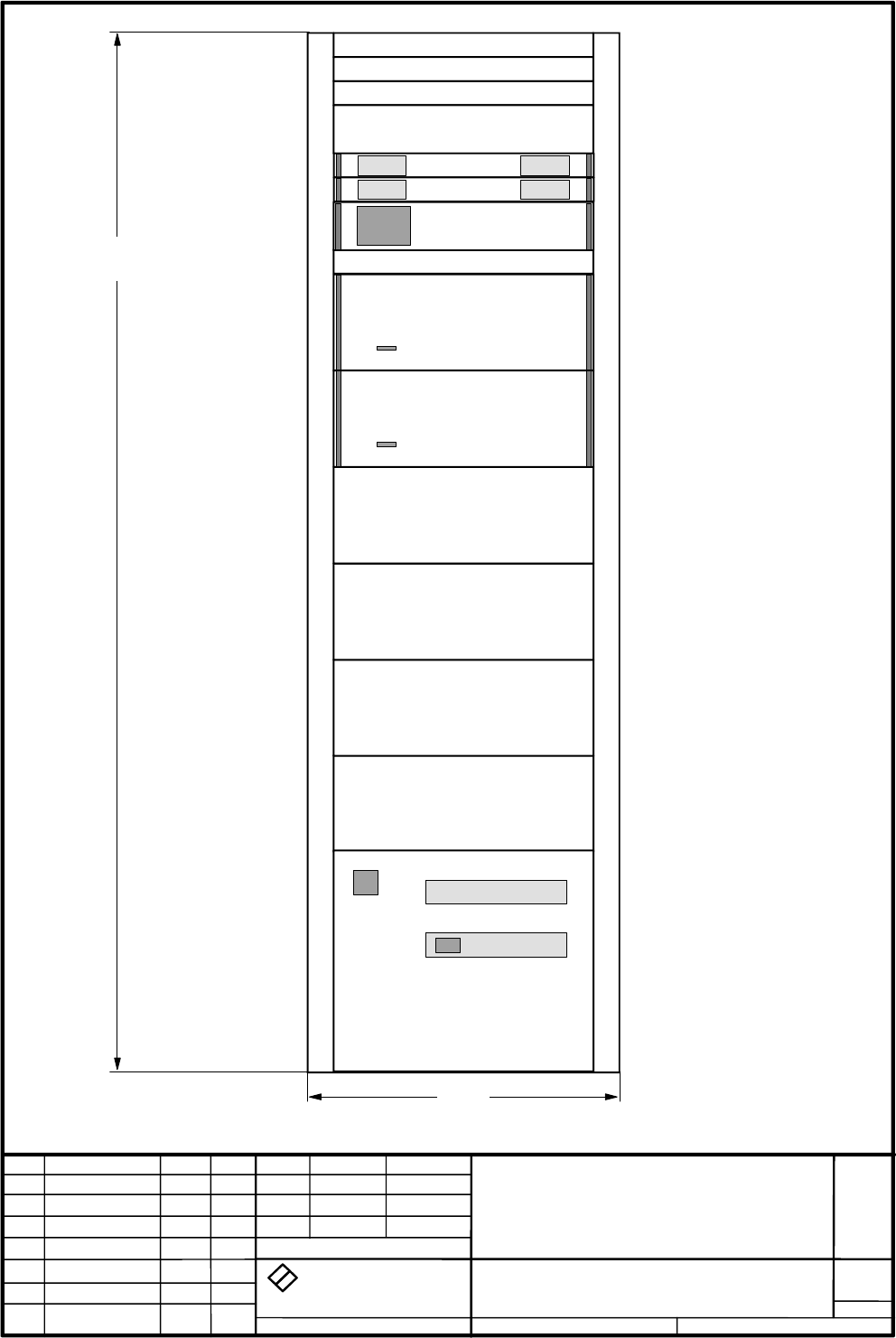
Tiefe: 800
Depth: 800
A200
A1
A100A
A100B
#)
A2
ROHDE & SCHWARZ
2000
600

Broadcasting Division
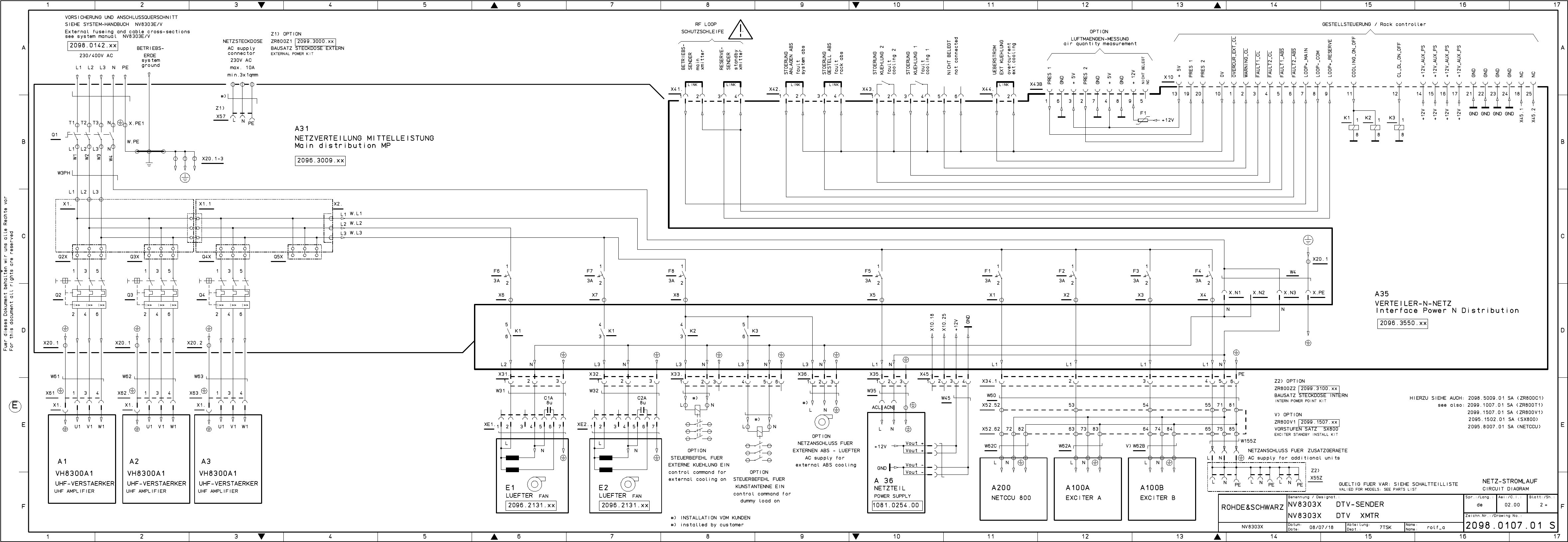
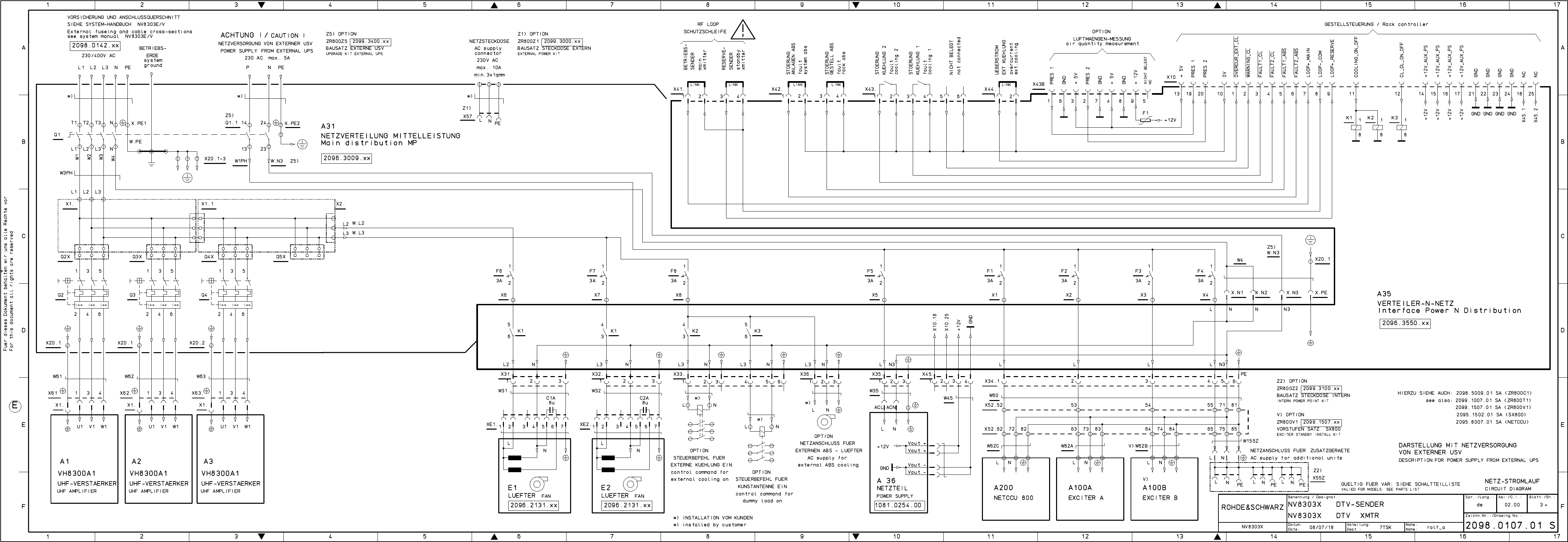
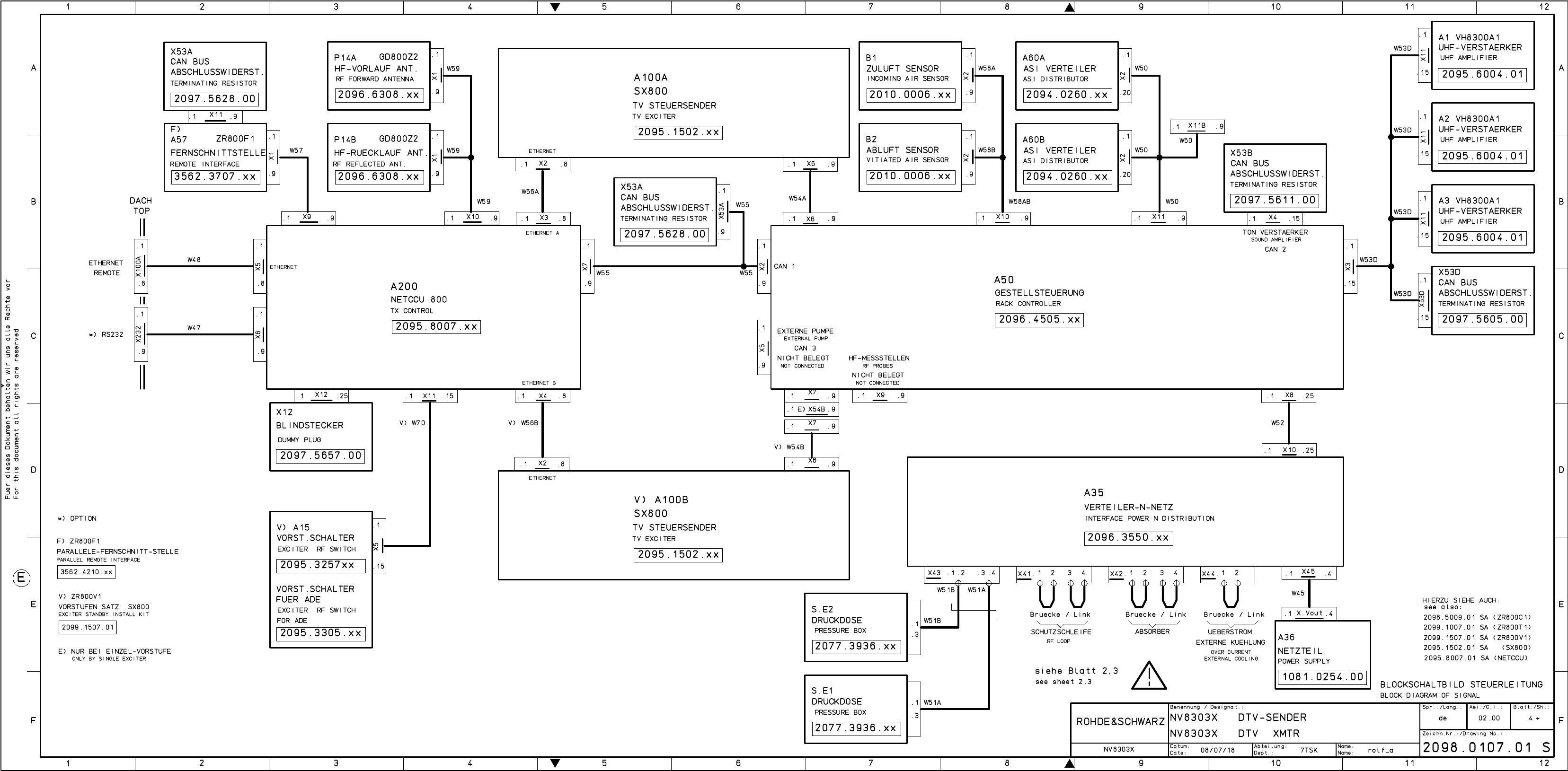
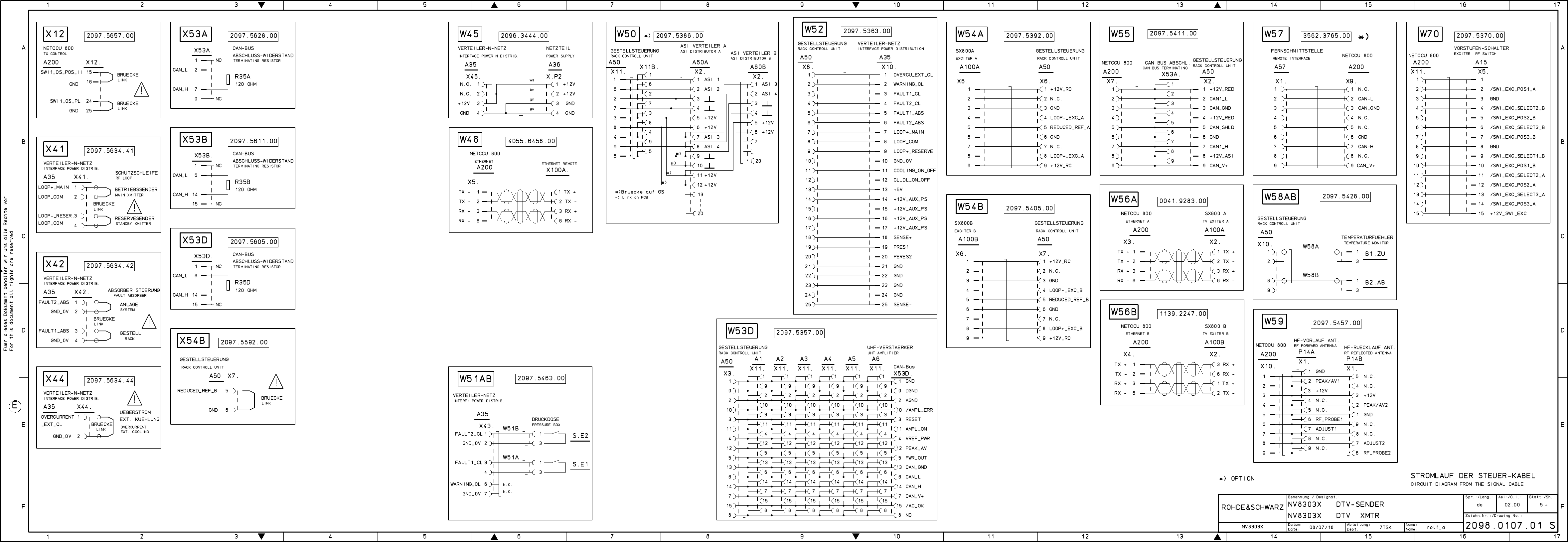
2098.0188.72 - 3 - E-1
Drawings and Diagrams
NV8303E/V
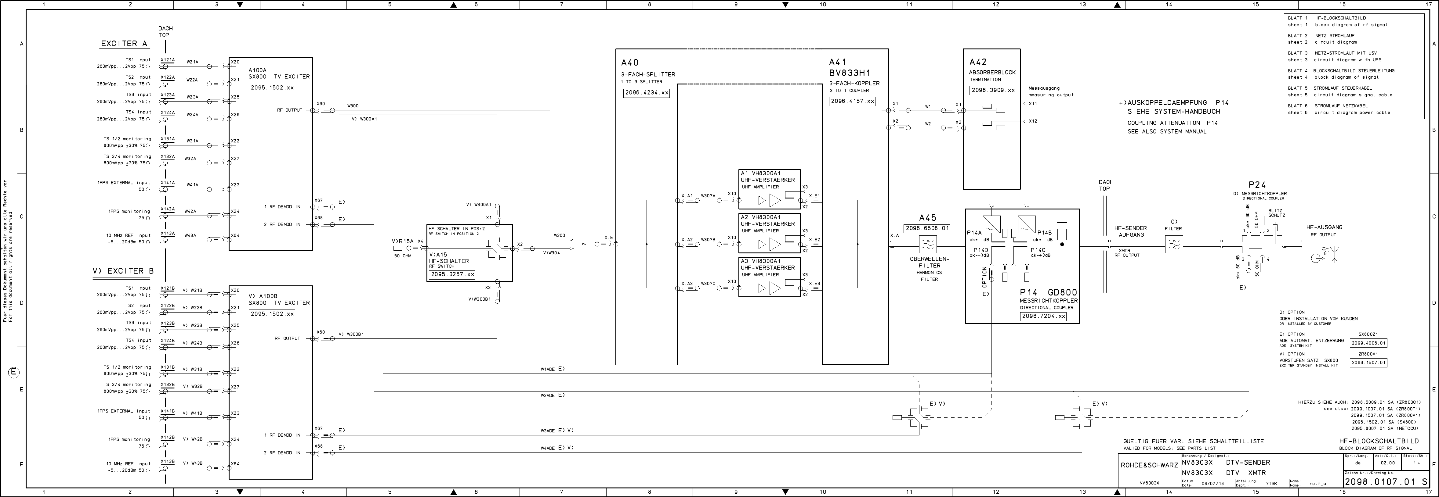
2098.0107.01
Printed in Germany


Für diese Unterlage behalten wir uns alle Rechte vor.
Ausgedruckte Dokumente unterliegen nicht dem Änderungsdienst.
For this document all rights are reserved.
Printed documents are not subject to revision
_
el.Kennz
Part Benennung / Hinweise
Designation Sachnummer
Stock No. Hersteller
Manufacturer Bestellbezeichnung
Designation enthalten in
contained in
a
Benennung/Designation
NV8303X DTV-SENDER
NV8303X DTV XMTR
Sprach./Lang
de en Ä.I. / C.I
01.00 Blatt/Sheet
1 of 1
Dokument Nr. / Document No.
2098.0107.01 SA
NV8303X Datum/
Date 2008-01-17 Abt. /
Dept. 7TSK Name /
Name Ro
ACHTUNG EGB /ATTENTION ESD
*VARIANTENERKLAERUNG
*EXPLANATION OF MODELS
VAR04=NV8303E DTV-SENDER MIT
EINZEL-VORSTUFE
PROGNOSESENDER
MOD04=NV8303E DTV-
TRANSMITTER WITH SINGLE
EXCITER
VAR24=NV8303V DTV-SENDER MIT
VORSTUFE-RESERVE OHNE ADE
PROGNOSESENDER
MOD24=NV8303V DTV
TRANSMITTER WITH DUAL DRIVE
WITHOUT ADE
VAR50=NV8303X DTV-SENDER
+++GRUNDSENDER+++
MOD50=NV8303X DTV-
TRANSMITTER ++BASIC
TRANSMITTER++
A1 - A3 GG VH8300A1 UHF-VERSTAER. 3-
Phasig
2095.6004.02 2098.0107.01
VH8300A1 UHF-AMPLIFIER
VAR 04 24
A20 GS ZR800T1 EINBAUS. SX800 2099.1007.03 2098.0107.01
ZR800T1 INSTAL. KIT
VAR 04 24
DTV - Ausfuehrung
A21 GS ZR800C1 LEISTUNGSSATZ 2098.5009.43 2098.0107.01
ZR800C1 POWER KIT
VAR 04 24
Leistungssatz fuer 3 Verstaerkern
A23 GS ZR800V1 VORST.SA SX800 2099.1507.04 2098.0107.01
ZR800V1 EXC.INST. KIT
VAR 24
Vorstufensatz - DTV ohne ADE
A200 GG NETCCU 800 CONTROL UNIT 2095.8007.02 2098.0107.01
NETCCU 800 CONTROL UNIT
VAR 04 24
A100A GG SX800 TV EXCITER DTV UND
ADE INT RF
2095.1502.71 2098.0107.01
SX800 TV EXCITER
VAR 04 24
A100B GG SX800 TV EXCITER DTV UND
ADE INT RF
2095.1502.71 2098.0107.01
SX800 TV EXCITER
VAR 24
DTV-TA NSMITTER BD.IV/V
R
S
7TSK
2098.0107 V
1
2098.0107.01
Benennung
Zeichn.-Nr.
Änderungs-
Mitteilung
Tag
Name
Bearb.
Gepr.
Norm
Änd.
Zust.
Tag
Name
zu Gerät
reg. i. V.
erste Z.
Blatt-Nr.
v. Bl.
ROHDE & SCHWARZ
RO
0000.0000.00
D
1
NV8303x
DTV-Sender Bd.IV/V
01.08
NV8303x
S\DESI-DAT\NV8300\NV8303x
01.00 01.08 RO
#)
OPTION Variantenerklärung siehe Schaltteilliste
Valid for model see parts list
Tiefe: 800
Depth: 800
A200
A1
A100A
A100B
#)
A2
A3
ROHDE & SCHWARZ
2000
600

Broadcasting Division
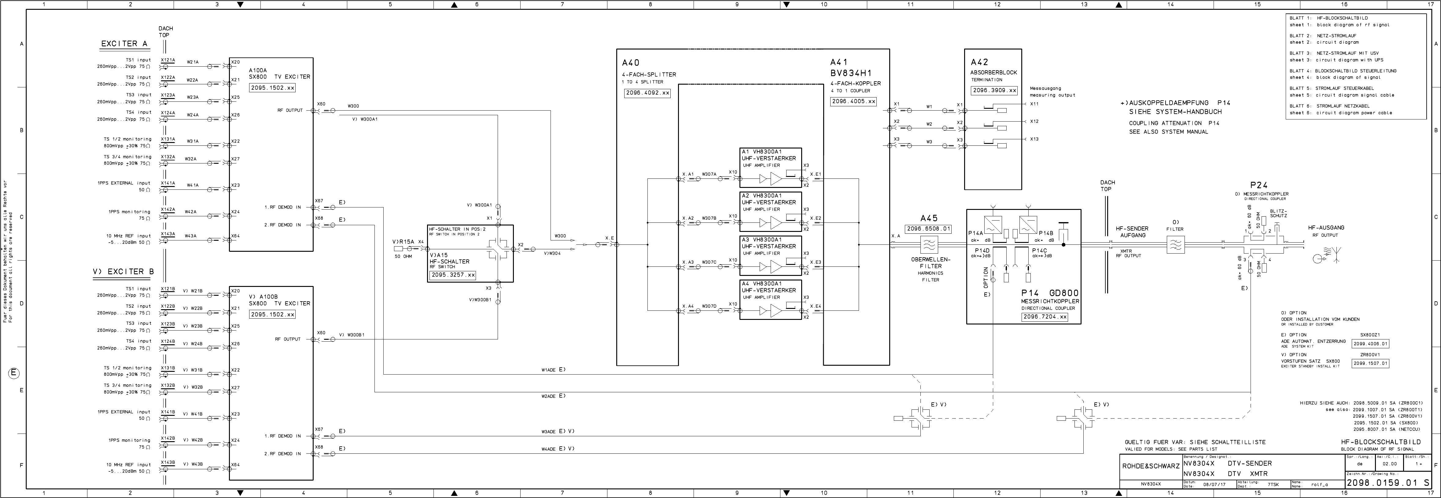
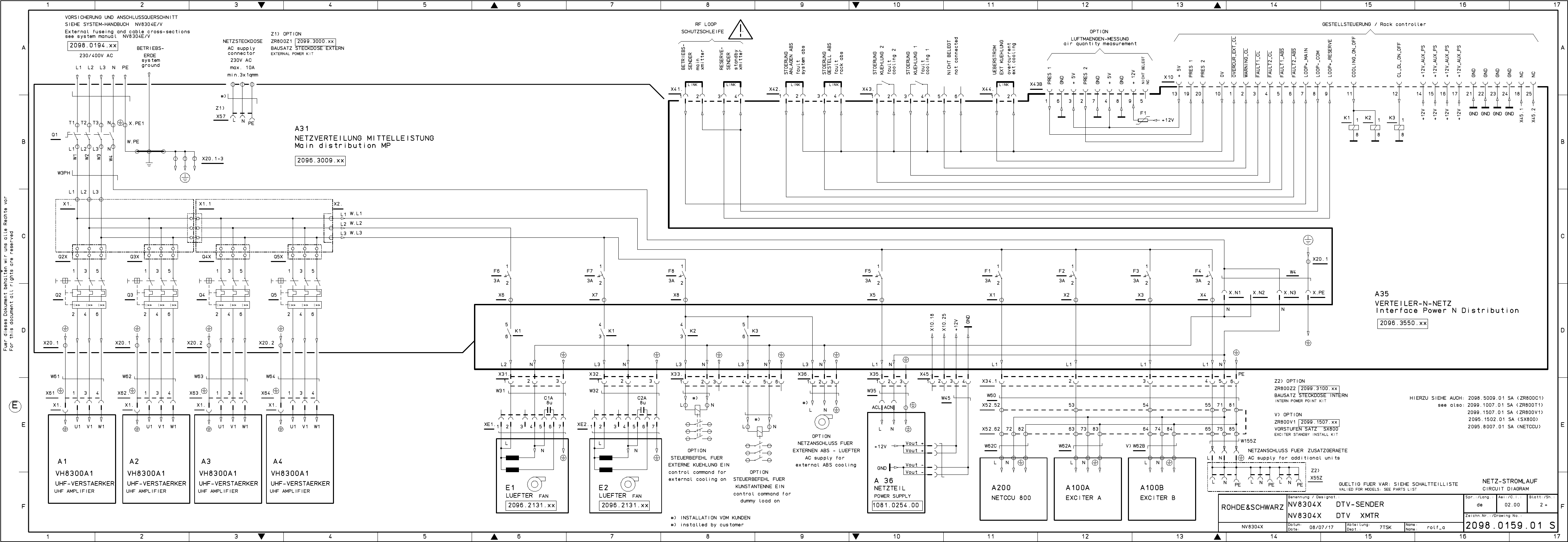
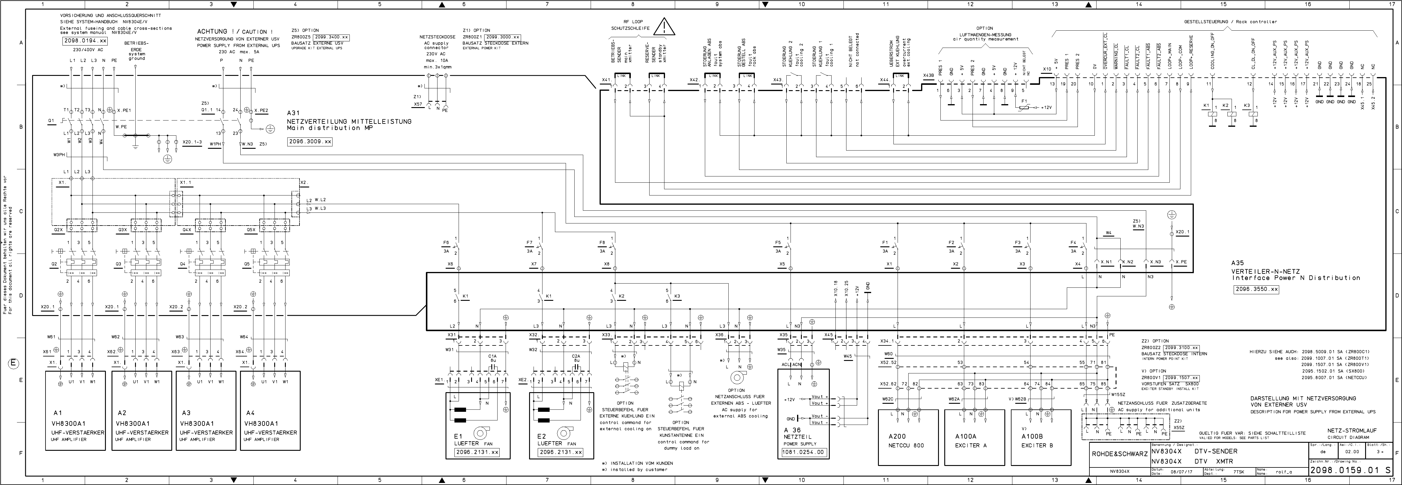
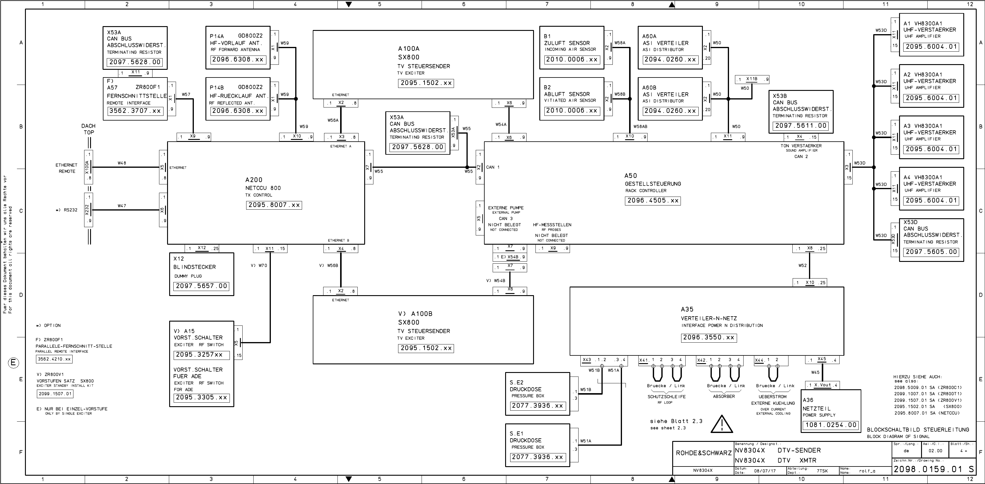
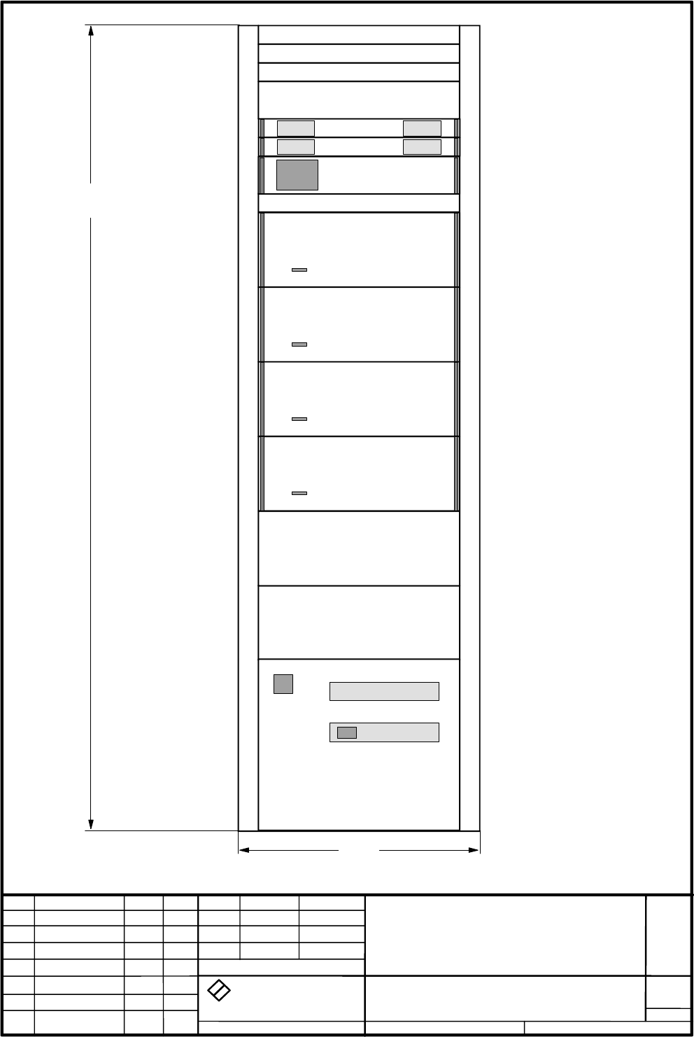
2098.0188.72 - 4 - E-1
Drawings and Diagrams
NV8304E/V
2098.0159.01
Printed in Germany


Für diese Unterlage behalten wir uns alle Rechte vor.
Ausgedruckte Dokumente unterliegen nicht dem Änderungsdienst.
For this document all rights are reserved.
Printed documents are not subject to revision
_
el.Kennz
Part Benennung / Hinweise
Designation Sachnummer
Stock No. Hersteller
Manufacturer Bestellbezeichnung
Designation enthalten in
contained in
a
Benennung/Designation
NV8304X DTV-SENDER
NV8304X DTV XMTR
Sprach./Lang
de en Ä.I. / C.I
01.00 Blatt/Sheet
1 of 1
Dokument Nr. / Document No.
2098.0159.01 SA
NV8304X Datum/
Date 2008-01-17 Abt. /
Dept. 7TSK Name /
Name Ro
ACHTUNG EGB /ATTENTION ESD
*VARIANTENERKLAERUNG
*EXPLANATION OF MODELS
VAR04=NV8304E DTV-SENDER MIT
EINZEL-VORSTUFE
PROGNOSESENDER
MOD04=NV8304E DTV-
TRANSMITTER WITH SINGLE
EXCITER
VAR24=NV8304V DTV-SENDER MIT
VORSTUFE-RESERVE OHNE ADE
PROGNOSESENDER
MOD24=NV8304V DTV
TRANSMITTER WITH DUAL DRIVE
WITHOUT ADE
VAR50=NV8304X DTV-SENDER
+++GRUNDSENDER+++
MOD50=NV8304X DTV-
TRANSMITTER ++BASIC
TRANSMITTER++
A1 - A4 GG VH8300A1 UHF-VERSTAER. 3-
Phasig
2095.6004.02 2098.0159.01
VH8300A1 UHF-AMPLIFIER
VAR 04 24
A20 GS ZR800T1 EINBAUS. SX800 2099.1007.03 2098.0159.01
ZR800T1 INSTAL. KIT
VAR 04 24
DTV - Ausfuehrung
A21 GS ZR800C1 LEISTUNGSSATZ 2098.5009.44 2098.0159.01
ZR800C1 POWER KIT
VAR 04 24
Leistungssatz fuer 4 Verstaerkern
A23 GS ZR800V1 VORST.SA SX800 2099.1507.04 2098.0159.01
ZR800V1 EXC.INST. KIT
VAR 24
Vorstufensatz - DTV ohne ADE
A200 GG NETCCU 800 CONTROL UNIT 2095.8007.02 2098.0159.01
NETCCU 800 CONTROL UNIT
VAR 04 24
A100A GG SX800 TV EXCITER DTV UND
ADE INT RF
2095.1502.71 2098.0159.01
SX800 TV EXCITER
VAR 04 24
A100B GG SX800 TV EXCITER DTV UND
ADE INT RF
2095.1502.71 2098.0159.01
SX800 TV EXCITER
VAR 24
DTV-TA NSMITTER BD.IV/V
R
S
7TSK
2098.0159 V
1
2098.0159.01
Benennung
Zeichn.-Nr.
Änderungs-
Mitteilung
Tag
Name
Bearb.
Gepr.
Norm
Änd.
Zust.
Tag
Name
zu Gerät
reg. i. V.
erste Z.
Blatt-Nr.
v. Bl.
ROHDE & SCHWARZ
RO
0000.0000.00
D
1
NV8304x
DTV-Sender Bd.IV/V
01.08
NV8304x
S\DESI-DAT\NV8300\NV8304x
01.00 01.08 RO
#)
OPTION Variantenerklärung siehe Schaltteilliste
Valid for model see parts list
Tiefe: 800
Depth: 800
A200
A1
A100A
A100B
#)
A2
A3
A4
ROHDE & SCHWARZ
2000
600

Broadcasting Division
2098.0188.72 - 5 - E-1
Spare Parts Lists
TRANSMITTERS
Printed in Germany

Für diese Unterlage behalten wir uns alle Rechte vor.
Ausgedruckte Dokumente unterliegen nicht dem Änderungsdienst.
For this document all rights are reserved.
Printed documents are not subject to revision
_
Pos.-Nr.
ItemNo Menge
Quantity ME
Unit El.Kennz
Ref.Des. Benennung / Bezeichnung
Designation Z Sachnummer
Stock No. Ersatzteil
Subst.part BA VH
Benennung/Designation
ERSATZTEILLISTE ZR800C1 LEISTUNGSS.
SPARE PART LIST FOR 2098.5009.01
Sprach./Lang
de en Ä.I. / C.I
04.00 Blatt/Sheet
1 of 10
Dokument Nr. / Document No.
2098.5067.01 ST
ZR800C1 Datum/
Date 2009-07-09 Abt. /
Dept. 7TSK Name /
Name RO
ACHTUNG EGB/ATTENTION ESD
*VARIANTENERKLAERUNG
*EXPLANATION OF MODELS
VAR11=MIT 1 VERSTAERKER BAND III
MOD11=WITH 1 AMPLIFIER BAND III
VAR12=MIT 2 VERSTAERKER BAND III
MOD12=WITH 2 AMPLIFIER BAND III
VAR13=MIT 3 VERSTAERKER BAND III
MOD13=WITH 3 AMPLIFIER BAND III
VAR14=MIT 4 VERSTAERKER BAND III
MOD14=WITH 4 AMPLIFIER BAND III
VAR15=MIT 5 VERSTAERKER BAND III
MOD15=WITH 5 AMPLIFIER BAND III
VAR16=MIT 6 VERSTAERKER BAND III
MOD16=WITH 6 AMPLIFIER BAND III
VAR21=MIT 1 VERSTAERKER BAND IV/V
MOD21=WITH 1 AMPLIFIER BAND IV/V
VAR22=MIT 2 VERSTAERKER BAND IV/V
MOD22=WITH 2 AMPLIFIER BAND IV/V
VAR23=MIT 3 VERSTAERKER BAND IV/V
MOD23=WITH 3 AMPLIFIER BAND IV/V
VAR24=MIT 4 VERSTAERKER BAND IV/V
MOD24=WITH 4 AMPLIFIER BAND IV/V
VAR25=MIT 5 VERSTAERKER BAND IV/V
MOD25=WITH 5 AMPLIFIER BAND IV/V
VAR26=MIT 6 VERSTAERKER BAND IV/V
MOD26=WITH 6 AMPLIFIER BAND IV/V
VAR31=FUER NX8300 MIT 1
VERSTAERKER BAND III
MOD31=FOR NX8300 WITH 1 AMPLIFIER
BAND III
VAR32=FUER NX8300 MIT 2
VERSTAERKER BAND III
MOD32=FOR NX8300 WITH 2 AMPLIFIER
BAND III
VAR33=FUER NX8300 MIT 3
VERSTAERKER BAND III
MOD33=FOR NX8300 WITH 3 AMPLIFIER
BAND III
VAR34=FUER NX8300 MIT 4
VERSTAERKER BAND III
MOD34=FOR NX8300 WITH 4 AMPLIFIER
BAND III
VAR35=FUER NX8300 MIT 5
VERSTAERKER BAND III
MOD35=FOR NX8300 WITH 5 AMPLIFIER
BAND III
VAR36=FUER NX8300 MIT 6
VERSTAERKER BAND III
MOD36=FOR NX8300 WITH 6 AMPLIFIER
BAND III
VAR41=FUER NX8300 MIT 1
VERSTAERKER BAND IV/V
MOD41=FOR NX8300 WITH 1 AMPLIFIER
BAND IV/V
VAR42=FUER NX8300 MIT 2
VERSTAERKER BAND IV/V
MOD42=FOR NX8300 WITH 2 AMPLIFIER
BAND IV/V
VAR43=FUER NX8300 MIT 3
VERSTAERKER BAND IV/V
MOD43=FOR NX8300 WITH 3 AMPLIFIER
BAND IV/V
VAR44=FUER NX8300 MIT 4
VERSTAERKER BAND IV/V
MOD44=FOR NX8300 WITH 4 AMPLIFIER
BAND IV/V
VAR45=FUER NX8300 MIT 5
VERSTAERKER BAND IV/V
MOD45=FOR NX8300 WITH 5 AMPLIFIER
BAND IV/V
VAR46=FUER NX8300 MIT 6
VERSTAERKER BAND IV/V

Für diese Unterlage behalten wir uns alle Rechte vor.
Ausgedruckte Dokumente unterliegen nicht dem Änderungsdienst.
For this document all rights are reserved.
Printed documents are not subject to revision
_
Pos.-Nr.
ItemNo Menge
Quantity ME
Unit El.Kennz
Ref.Des. Benennung / Bezeichnung
Designation Z Sachnummer
Stock No. Ersatzteil
Subst.part BA VH
Benennung/Designation
ERSATZTEILLISTE ZR800C1 LEISTUNGSS.
SPARE PART LIST FOR 2098.5009.01
Sprach./Lang
de en Ä.I. / C.I
04.00 Blatt/Sheet
2 of 10
Dokument Nr. / Document No.
2098.5067.01 ST
ZR800C1 Datum/
Date 2009-07-09 Abt. /
Dept. 7TSK Name /
Name RO
MOD46=FOR NX8300 WITH 6 AMPLIFIER
BAND IV/V
VAR51=FUER NX8300X1 MIT 1
VERSTAERKER BAND III
MOD51=FOR NX8300X1 WITH 1
AMPLIFIER BAND III
VAR52=FUER NX8300X1 MIT 2
VERSTAERKER BAND III
MOD52=FOR NX8300X1 WITH 2
AMPLIFIER BAND III
VAR53=FUER NX8300X1 MIT 3
VERSTAERKER BAND III
MOD53=FOR NX8300X1 WITH 3
AMPLIFIER BAND III
VAR54=FUER NX8300X1 MIT 4
VERSTAERKER BAND III
MOD54=FOR NX8300X1 WITH 4
AMPLIFIER BAND III
VAR55=FUER NX8300X1 MIT 5
VERSTAERKER BAND III
MOD55=FOR NX8300X1 WITH 5
AMPLIFIER BAND III
VAR56=FUER NX8300X1 MIT 6
VERSTAERKER BAND III
MOD56=FOR NX8300X1 WITH 6
AMPLIFIER BAND III
VAR61=FUER NX8300X1 MIT 1
VERSTAERKER BAND IV/V
MOD61=FOR NX8300X1 WITH 1
AMPLIFIER BAND IV/V
VAR62=FUER NX8300X1 MIT 2
VERSTAERKER BAND IV/V
MOD62=FOR NX8300X1 WITH 2
AMPLIFIER BAND IV/V
VAR63=FUER NX8300X1 MIT 3
VERSTAERKER BAND IV/V
MOD63=FOR NX8300X1 WITH 3
AMPLIFIER BAND IV/V
VAR64=FUER NX8300X1 MIT 4
VERSTAERKER BAND IV/V
MOD64=FOR NX8300X1 WITH 4
AMPLIFIER BAND IV/V
VAR65=FUER NX8300X1 MIT 5
VERSTAERKER BAND IV/V
MOD65=FOR NX8300X1 WITH 5
AMPLIFIER BAND IV/V
VAR66=FUER NX8300X1 MIT 6
VERSTAERKER BAND IV/V
MOD66=FOR NX8300X1 WITH 6
AMPLIFIER BAND IV/V
1000 0 S PB BEMERKUNG 0999.9610.00 B O
NOTE
Pos.: 1010 bis 1990
HF - Komponenten
1020 1 S A41 ZE BV822M1 2FACH-KOPPLER Z 2099.5502.02 M
BV822M1 TWOF. COUPLER
VAR 12 32 52
## Verwendet in:
## 2098.5009.01
1030 1 S A41 ZE BV823M1 3FACH-KOPPLER Z 2099.5702.02 M
BV823M1 3F. COUPLER
VAR 13 33 53
## Verwendet in:
## 2098.5009.01
1040 1 S A41 ZE BV824M1 4FACH-KOPPLER Z 2099.5602.02 M
BV824M1 QUADRUPLE COUPLER
VAR 14 34 54
## Verwendet in:
## 2098.5009.01
1050 1 S A41 ZE BV825M1 5FACH-KOPPLER Z 2099.5802.02 M

Für diese Unterlage behalten wir uns alle Rechte vor.
Ausgedruckte Dokumente unterliegen nicht dem Änderungsdienst.
For this document all rights are reserved.
Printed documents are not subject to revision
_
Pos.-Nr.
ItemNo Menge
Quantity ME
Unit El.Kennz
Ref.Des. Benennung / Bezeichnung
Designation Z Sachnummer
Stock No. Ersatzteil
Subst.part BA VH
Benennung/Designation
ERSATZTEILLISTE ZR800C1 LEISTUNGSS.
SPARE PART LIST FOR 2098.5009.01
Sprach./Lang
de en Ä.I. / C.I
04.00 Blatt/Sheet
3 of 10
Dokument Nr. / Document No.
2098.5067.01 ST
ZR800C1 Datum/
Date 2009-07-09 Abt. /
Dept. 7TSK Name /
Name RO
BV825M1 5F. COUPLER
VAR 15 35 55
## Verwendet in:
## 2098.5009.01
1060 1 S A41 ZE BV826M1 6FACH-KOPPLER Z 2099.5902.02 M
BV826M1 6F. COUPLER
VAR 16 36 56
## Verwendet in:
## 2098.5009.01
1120 1 S A41 ZE BV832H1 2FACH-KOPPLER Z 2096.4305.02 M
BV832H1 2 WAY COUPLER
VAR 22 42 62
## Verwendet in:
## 2098.5009.01
1130 1 S A41 ZE BV833H1 3FACH-KOPPLER Z 2096.4157.02 M
BV833H1 TRIPLE COUPLER
VAR 23 43 63
## Verwendet in:
## 2098.5009.01
1140 1 S A41 ZE BV834H1 4FACH-KOPPLER Z 2096.4005.02 M
BV834H1 FOURFOLD COUPL
VAR 24 44 64
## Verwendet in:
## 2098.5009.01
1150 1 S A41 ZE BV835H1 5FACH-KOPPLER Z 2096.4705.02 M
BV835H1 FIVEFOLD COUPL
VAR 25 45 65
## Verwendet in:
## 2098.5009.01
1160 1 S A41 ZE BV836H1 6FACH-KOPPLER Z 2096.3750.02 M
BV836H1 SIXFOLD COUPL.
VAR 26 46 66
## Verwendet in:
## 2098.5009.01
1220 1 S A42 ZE ABS-BLOCK ML NX8000 Z 2096.3909.32 M
ABS BLOCK MP NX8000
VAR 12 13 32 33 52 53
## Verwendet in:
## 2098.5009.01
1240 1 S A42 ZE ABS-BLOCK ML NX8000 Z 2096.3909.35 M
ABS BLOCK MP NX8000
VAR 14 15 16 34 35 36 54 55 56
## Verwendet in:
## 2098.5009.01
1320 1 S A42 ZE ABS-BLOCK ML NX8000 Z 2096.3909.03 M
ABS BLOCK MP NX8000
VAR 22 23 42 43 62 63
## Verwendet in:
## 2098.5009.01
1340 1 S A42 ZE ABS-BLOCK ML NX8000 Z 2096.3909.02 M
ABS BLOCK MP NX8000
VAR 24 25 26 44 45 46 64 65 66
## Verwendet in:
## 2098.5009.01
1410 1 S A45 ZM FM825 OWF - BD. 3 Z 2096.7304.00 M O
FM825 H.FILT. BD. 3
VAR 11 12 13 14 15 16 31 32 33 34 35 36 51
52 53 54 55 56
## Verwendet in:
## 2098.5009.01
1450 1 S A45 ZM FH825 OWF - BD. 4/5 Z 2096.6508.02 M O
FH825 H.FILT. BD. 4/5

Für diese Unterlage behalten wir uns alle Rechte vor.
Ausgedruckte Dokumente unterliegen nicht dem Änderungsdienst.
For this document all rights are reserved.
Printed documents are not subject to revision
_
Pos.-Nr.
ItemNo Menge
Quantity ME
Unit El.Kennz
Ref.Des. Benennung / Bezeichnung
Designation Z Sachnummer
Stock No. Ersatzteil
Subst.part BA VH
Benennung/Designation
ERSATZTEILLISTE ZR800C1 LEISTUNGSS.
SPARE PART LIST FOR 2098.5009.01
Sprach./Lang
de en Ä.I. / C.I
04.00 Blatt/Sheet
4 of 10
Dokument Nr. / Document No.
2098.5067.01 ST
ZR800C1 Datum/
Date 2009-07-09 Abt. /
Dept. 7TSK Name /
Name RO
VAR 21 22 23 24 25 26 41 42 43 44 45 46 61
62 63 64 65 66
## Verwendet in:
## 2098.5009.01
1510 1 S P14 ZE GD800 MESSRICHTKOPPLER Z 2096.7204.34 M
DIRECTION COUPLER
VAR 11 12 13 14 15 16 31 32 33 34 35 36 51
52 53 54 55 56
## Verwendet in:
## 2098.5009.01
1520 1 S P14 ZE GD800 MESSRICHTKOPPLER Z 2096.7204.44 M
DIRECTION COUPLER
VAR 21 22 23 24 25 26 41 42 43 44 45 46 61
62 63 64 65 66
## Verwendet in:
## 2098.5009.01
1530 1 S P14A ZM GD800Z2 MESSSYSTEM Z 2096.6308.30 M O
GD800Z2 MEASURING SYST
VAR 11 12 13 14 15 16 31 32 33 34 35 36 51
52 53 54 55 56
## Verwendet in:
## 2096.7204.01
1540 1 S P14A ZM GD800Z2 MESSSYSTEM Z 2096.6308.40 M O
GD800Z2 MEASURING SYST
VAR 21 22 23 24 25 26 41 42 43 44 45 46 61
62 63 64 65 66
## Verwendet in:
## 2096.7204.01
1550 1 S P14B ZM GD800Z2 MESSSYSTEM Z 2096.6308.30 M O
GD800Z2 MEASURING SYST
VAR 11 12 13 14 15 16 31 32 33 34 35 36 51
52 53 54 55 56
## Verwendet in:
## 2096.7204.01
1560 1 S P14B ZM GD800Z2 MESSSYSTEM Z 2096.6308.40 M O
GD800Z2 MEASURING SYST
VAR 21 22 23 24 25 26 41 42 43 44 45 46 61
62 63 64 65 66
## Verwendet in:
## 2096.7204.01
1570 1 S P14C ZM GD800Z1 MESSSYSTEM Z 2096.6208.02 M O
GD800Z1 MEASURING SYST
## Verwendet in:
## 2096.7204.01
1580 1 S P14D ZM GD800Z1 MESSSYSTEM Z 2096.6208.03 M O
GD800Z1 MEASURING SYST
## Verwendet in:
## 2096.7204.01
1590 1 S P14ZP ED RF-AUSGANG Z2 Z 2096.6408.02 M O
RF_OUTPUT Z2
## Verwendet in:
## 2096.7204.01
Zum Einstellen der Auskoppeldaempfung fuer
P14A, P14B, P14C und P14D.
1610 1 S W.A1 DH KABEL L=1M S/S 7/16 2087.7111.00 B O
CABLE
VAR 11 21 31 41 51 61
## Verwendet in:
## 2098.5009.01
1620 1 S X.A ZM UEBERGANG 7/16BU-RL13/30M Z 2096.7004.00 M O
Adaptor 7/16BU-RL13/30M
VAR 11 21 31 41 51 61
## Verwendet in:
## 2098.5009.01

Für diese Unterlage behalten wir uns alle Rechte vor.
Ausgedruckte Dokumente unterliegen nicht dem Änderungsdienst.
For this document all rights are reserved.
Printed documents are not subject to revision
_
Pos.-Nr.
ItemNo Menge
Quantity ME
Unit El.Kennz
Ref.Des. Benennung / Bezeichnung
Designation Z Sachnummer
Stock No. Ersatzteil
Subst.part BA VH
Benennung/Designation
ERSATZTEILLISTE ZR800C1 LEISTUNGSS.
SPARE PART LIST FOR 2098.5009.01
Sprach./Lang
de en Ä.I. / C.I
04.00 Blatt/Sheet
5 of 10
Dokument Nr. / Document No.
2098.5067.01 ST
ZR800C1 Datum/
Date 2009-07-09 Abt. /
Dept. 7TSK Name /
Name RO
1630 1 S DV RG400 2XN/W U 1,4M Z 2097.5792.00 M O
RF-CABLE
VAR 12 13 14 15 16 22 23 24 25 26 32 33 34
35 36 42 43 44 45 46 52 53 54 55 56 62 63
64 65 66
## Verwendet in:
## 2098.5009.01
1640 1 S DV RG400 2XN/W U 0,6M Z 2097.5805.00 M O
RF-CABLE
VAR 15 16 25 26 35 36 45 46 55 56 65 66
## Verwendet in:
## 2098.5009.01
1650 1 S DH KABEL SCF 2XN-W 1.1M U 2097.5863.00 B O
RF CABLE
VAR 14 15 16 24 25 26 34 35 36 44 45 46 54
55 56 64 65 66
## Verwendet in:
## 2098.5009.01
1710 1 S ZM UEBERGANG 1 5/8EIA-RL13/30R Z 2096.6966.00 M O
Adaptor 1 5/8EIA-RL13/30R
## Verwendet in:
## 2098.5009.01
1720 1 S FK KUPPLUNG EIA 1 5/8 0656.2279.00 B V
ADAPTOR FOR TRANSMISSION LINE 1 5/8
## Verwendet in:
## 2098.5009.01
2000 0 S PB BEMERKUNG 0999.9610.00 B O
NOTE
Pos.: 2010 bis 2990
Netzverteilung - Komponenten
2010 1 S X1 SL 3PH SAM.SCH. EINSP. LI 2096.5053.00 B O
3PH CURR. DISTRIB. LEF
VAR 11 12 13 14 15 16 21 22 23 24 25 26 31
32 33 34 35 36 41 42 43 44 45 46
## Verwendet in:
## 2096.3009.01
2020 1 S X1.1 SL 3PH SAM.SCH. ERWEIT.2X 2096.5060.00 B O
3PH CURR. DISTRIB. 2X
VAR 13 14 16 23 24 26 33 34 36 43 44 46
## Verwendet in:
## 2096.3344.01
X1.2
2030 1 S X1.1 SL 3PH SAM.SCH. ERWEIT.3X 2096.5076.00 B O
3PH CURR. DISTRIB. 3X
VAR 15 25 36 46
## Verwendet in:
## 2096.3344.01
2040 1 S X2 VK KLEMMBLOCK 0.5-6QMM 2096.5124.00 B B
TERMINAL BLOCK
VAR 11 12 13 14 15 16 21 22 23 24 25 26 31
32 33 34 35 36 41 42 43 44 45 46
## Verwendet in:
## 2096.3009.01
2050 1 S F1 SS SCHUTZSCHALTER T-M 1P 3A - C 2096.5030.00 B O
PROTECT SWITCH 1P 3A - C
VAR 11 12 13 14 15 16 21 22 23 24 25 26 31
32 33 34 35 36 41 42 43 44 45 46
## Verwendet in:
## 2096.3009.01
F2
F3
F4
F5
F6

Für diese Unterlage behalten wir uns alle Rechte vor.
Ausgedruckte Dokumente unterliegen nicht dem Änderungsdienst.
For this document all rights are reserved.
Printed documents are not subject to revision
_
Pos.-Nr.
ItemNo Menge
Quantity ME
Unit El.Kennz
Ref.Des. Benennung / Bezeichnung
Designation Z Sachnummer
Stock No. Ersatzteil
Subst.part BA VH
Benennung/Designation
ERSATZTEILLISTE ZR800C1 LEISTUNGSS.
SPARE PART LIST FOR 2098.5009.01
Sprach./Lang
de en Ä.I. / C.I
04.00 Blatt/Sheet
6 of 10
Dokument Nr. / Document No.
2098.5067.01 ST
ZR800C1 Datum/
Date 2009-07-09 Abt. /
Dept. 7TSK Name /
Name RO
F7
F8
2090 1 S W1PH DX W1PH VERTEILER N-NETZ Z 2096.3538.02 M
W1PH MAIN DISTRIBUTOR
VAR 11 12 13 14 15 16 21 22 23 24 25 26 31
32 33 34 35 36 41 42 43 44 45 46
## Verwendet in:
## 2096.3009.01
2110 1 S Q1 SL LEISTUNGSTRENNER 32A/400V 2093.8522.00 B O
MAINSWITCH 32A/400V
VAR 11 12 13 14 15 16 21 22 23 24 25 26 31
32 33 34 35 36 41 42 43 44 45 46
## Verwendet in:
## 2096.3344.01
2120 1 S Q1.N SL 4.SCHALTGLIED (N-LEIT) 2096.5024.00 B O
4. SWITCH N-CONTACT
VAR 11 12 13 14 15 16 21 22 23 24 25 26 31
32 33 34 35 36 41 42 43 44 45 46
## Verwendet in:
## 2096.3344.01
2130 1 S Q2 SS SCHUTZSCHALTER T-M 3P 3.5-5A 2096.5153.00 B O
PROTECT SWITCH 3P 3.5-5A
VAR 11 12 13 14 15 16 21 22 23 24 25 26 31
32 33 34 35 36 41 42 43 44 45 46
## Verwendet in:
## 2096.3344.01
Q3
Q4
Q5
Q6
Q7
2140 1 S Q2X SL 3PH VERBINDUNGSSTECKER 2096.5082.00 B O
3PH PLUG LINK
VAR 11 12 13 14 15 16 21 22 23 24 25 26 31
32 33 34 35 36 41 42 43 44 45 46
## Verwendet in:
## 2096.3344.01
Q3X
Q4X
Q5X
Q6X
Q7X
2150 1 S X20.1 VK SCHUTZLEITERKL.2.5QMM 2091.9773.00 B V
VAR 11 12 13 14 15 16 21 22 23 24 25 26 31
32 33 34 35 36 41 42 43 44 45 46
## Verwendet in:
## 2096.3009.01
X20.2
X20.3
2400 1 S X33 DX WAGO BRUECKEN-STECKER Z 2097.5634.33 M O
DUMMY PLUG
VAR 11 12 13 14 15 16 21 22 23 24 25 26 31
32 33 34 35 36 41 42 43 44 45 46
## Verwendet in:
## 2096.3344.01
2410 1 S X36 DX WAGO BRUECKEN-STECKER Z 2097.5634.36 M O
DUMMY PLUG
VAR 11 12 13 14 15 16 21 22 23 24 25 26 31
32 33 34 35 36 41 42 43 44 45 46
## Verwendet in:
## 2096.3344.01
2420 1 S X41 DX WAGO BRUECKEN-STECKER Z 2097.5634.41 M O
DUMMY PLUG
VAR 11 12 13 14 15 16 21 22 23 24 25 26 31
32 33 34 35 36 41 42 43 44 45 46
## Verwendet in:

Für diese Unterlage behalten wir uns alle Rechte vor.
Ausgedruckte Dokumente unterliegen nicht dem Änderungsdienst.
For this document all rights are reserved.
Printed documents are not subject to revision
_
Pos.-Nr.
ItemNo Menge
Quantity ME
Unit El.Kennz
Ref.Des. Benennung / Bezeichnung
Designation Z Sachnummer
Stock No. Ersatzteil
Subst.part BA VH
Benennung/Designation
ERSATZTEILLISTE ZR800C1 LEISTUNGSS.
SPARE PART LIST FOR 2098.5009.01
Sprach./Lang
de en Ä.I. / C.I
04.00 Blatt/Sheet
7 of 10
Dokument Nr. / Document No.
2098.5067.01 ST
ZR800C1 Datum/
Date 2009-07-09 Abt. /
Dept. 7TSK Name /
Name RO
## 2096.3344.01
2430 1 S X42 DX WAGO BRUECKEN-STECKER Z 2097.5634.42 M O
DUMMY PLUG
VAR 11 12 13 14 15 16 21 22 23 24 25 26 31
32 33 34 35 36 41 42 43 44 45 46
## Verwendet in:
## 2096.3344.01
2440 1 S X44 DX WAGO BRUECKEN-STECKER Z 2097.5634.44 M O
DUMMY PLUG
VAR 11 12 13 14 15 16 21 22 23 24 25 26 31
32 33 34 35 36 41 42 43 44 45 46
## Verwendet in:
## 2096.3344.01
2500 1 S A35 ED VERTEILER-N-NETZ Z 2096.3550.02 M
INTERFACE POWER DISTR.
VAR 11 12 13 14 15 16 21 22 23 24 25 26 31
32 33 34 35 36 41 42 43 44 45 46
## Verwendet in:
## 2096.3009.01
2510 1 S A36 NJ SCHALTNETZT. AC90-264V 1081.0254.00 B B
POWER SUPPLY 12V/40W
VAR 11 12 13 14 15 16 21 22 23 24 25 26 31
32 33 34 35 36 41 42 43 44 45 46
## Verwendet in:
## 2096.3009.01
2610 1 S W35 DX W35 NETZKAB.-HILFSSPG. Z 2096.3450.00 M O
W35 MAIN POWER KABLE
VAR 11 12 13 14 15 16 21 22 23 24 25 26 31
32 33 34 35 36 41 42 43 44 45 46
## Verwendet in:
## 2096.3009.01
2620 1 S W45 DX W45 DC-KABEL-HILFSSPG. Z 2096.3444.00 M O
W45 DC CABLE
VAR 11 12 13 14 15 16 21 22 23 24 25 26 31
32 33 34 35 36 41 42 43 44 45 46
## Verwendet in:
## 2096.3009.01
3000 0 S PB BEMERKUNG 0999.9610.00 B O
NOTE
Pos.: 3010 bis 3990
Gestell - Komponenten
3010 1 S A50 EE RACK CONTROLLER Z 2096.4505.02 M O
RACK CONTROLLER
## Verwendet in:
## 2098.5009.01
3110 1 S X53A DX CAN ABSCHL. 9POL.X53A Z 2097.5628.00 M O
CAN TERMINATING X53A
## Verwendet in:
## 2098.5009.01
3120 1 S X53B DX CAN ABSCHL. 15POL.X53B Z 2097.5611.00 M O
CAN TERMINATING X53B
## Verwendet in:
## 2098.5009.01
3130 1 S X53D DX CAN ABSCHL. 15POL.X53D Z 2097.5605.00 M O
CAN TERMINATING X53D
## Verwendet in:
## 2098.5009.01
3150 1 S X54B DX BRUECKEN-ST REF.SPG.-REDUZ.
A50/X7 Z 2097.5592.00 M
DUMMY PLUG REDUCED_REF_B A50/X7
## Verwendet in:
## 2098.5009.01

Für diese Unterlage behalten wir uns alle Rechte vor.
Ausgedruckte Dokumente unterliegen nicht dem Änderungsdienst.
For this document all rights are reserved.
Printed documents are not subject to revision
_
Pos.-Nr.
ItemNo Menge
Quantity ME
Unit El.Kennz
Ref.Des. Benennung / Bezeichnung
Designation Z Sachnummer
Stock No. Ersatzteil
Subst.part BA VH
Benennung/Designation
ERSATZTEILLISTE ZR800C1 LEISTUNGSS.
SPARE PART LIST FOR 2098.5009.01
Sprach./Lang
de en Ä.I. / C.I
04.00 Blatt/Sheet
8 of 10
Dokument Nr. / Document No.
2098.5067.01 ST
ZR800C1 Datum/
Date 2009-07-09 Abt. /
Dept. 7TSK Name /
Name RO
3500 1 S W48 DG PATCHKABEL 2M 1-1 BL 4055.6458.00 B T
PATCHCABEL 2M 1-1 BL
## Verwendet in:
## 2098.5009.01
3600 1 M WW DICHTUNGSSCHAUMBAND PVC 8X6
14SH 2096.2119.00 B B
SEALING TAPE
## Verwendet in:
## 2096.2002.01
3710 1 S KZ FUEHLSTIFT RD2.7X17.5 0043.5727.00 M V
GUIDE PIN
VAR 11 12 13 14 21 22 23 24 31 32 33 34 41
42 43 44 51 52 53 54 61 62 63 64
## Verwendet in:
## 2096.2231.01
3720 1 S MF ANSCHLUSSHALTER 2096.2290.00 M O
CONNECTION HOLDER
VAR 11 12 13 14 21 22 23 24 31 32 33 34 41
42 43 44 51 52 53 54 61 62 63 64
## Verwendet in:
## 2096.2231.01
3800 1 S MZ ABDECKUNG 2 2096.2925.00 M O
COVER 2
VAR 11 12 13 14 15 21 22 23 24 25 31 32 33
34 35 41 42 43 44 45 51 52 53 54 55 61 62
63 64 65
## Verwendet in:
## 2099.5019.00
3900 1 S E1 ZE LUEFTERSATZ ML Z 2096.2131.02 M
FAN KIT MP
VAR 11 12 13 14 15 16 21 22 23 24 25 26
## Verwendet in:
## 2096.2377.01
E2
3910 1 S SL LEISTUNGSTRENNSCHALTER 63A 2096.5001.00 B O
63A MAIN POWER SWITCH
VAR 51 52 53 54 55 61 62 63 64 65
##Verwendet in:
##2096.2154.01
3920 1 S SL 4.SCHALTGLIED (N-LEIT) 2096.5018.00 B O
4. SWITCH N-CONTACT
VAR 51 52 53 54 55 61 62 63 64 65
##Verwendet in:
##2096.2154.01
3930 1 S SL LEISTUNGSSCHALT.4P125A 2093.8839.00 B O
POWER SWITCH 4P 124A
VAR 56 66
##Verwendet in:
##2096.2154.01
3940 1 S SS SCHUTZSCHALTER TM 2P 15A / C 2096.5224.00 B O
PROTECT SWITCH 2P 15A - C
VAR 51 52 53 54 55 56 61 62 63 64 65 66
##Verwendet in:
##2096.2154.01
3950 1 S SS SCHUTZSCHALTER T-M 1P 3A - C 2096.5030.00 B O
PROTECT SWITCH 1P 3A - C
VAR 51 52 53 54 55 56 61 62 63 64 65 66
##Verwendet in:
##2096.2154.01
3960 1 S SS SCHUTZSCHALTER T-M 1P 6A - C 2096.5047.00 B O
PROTECT SWITCH 1P 6A - C
VAR 51 52 53 54 55 56 61 62 63 64 65 66
##Verwendet in:
##2096.2154.01

Für diese Unterlage behalten wir uns alle Rechte vor.
Ausgedruckte Dokumente unterliegen nicht dem Änderungsdienst.
For this document all rights are reserved.
Printed documents are not subject to revision
_
Pos.-Nr.
ItemNo Menge
Quantity ME
Unit El.Kennz
Ref.Des. Benennung / Bezeichnung
Designation Z Sachnummer
Stock No. Ersatzteil
Subst.part BA VH
Benennung/Designation
ERSATZTEILLISTE ZR800C1 LEISTUNGSS.
SPARE PART LIST FOR 2098.5009.01
Sprach./Lang
de en Ä.I. / C.I
04.00 Blatt/Sheet
9 of 10
Dokument Nr. / Document No.
2098.5067.01 ST
ZR800C1 Datum/
Date 2009-07-09 Abt. /
Dept. 7TSK Name /
Name RO
3970 1 S ED VERTEILER-N-NETZ Z 2096.3550.02 M
INTERFACE POWER DISTR.
VAR 51 52 53 54 55 56 61 62 63 64 65 66
##Verwendet in:
##2096.2154.01
3980 1 S DX WAGO BRUECKEN-STECKER Z 2097.5634.33 M O
DUMMY PLUG
VAR 51 52 53 54 55 56 61 62 63 64 65 66
##Verwendet in:
##2096.2154.01
3990 1 S DX WAGO BRUECKEN-STECKER Z 2097.5634.36 M O
DUMMY PLUG
VAR 51 52 53 54 55 56 61 62 63 64 65 66
##Verwendet in:
##2096.2154.01
4000 1 S DX WAGO BRUECKEN-STECKER Z 2097.5634.41 M O
DUMMY PLUG
VAR 51 52 53 54 55 56 61 62 63 64 65 66
##Verwendet in:
##2096.2154.01
4010 1 S DX WAGO BRUECKEN-STECKER Z 2097.5634.42 M O
DUMMY PLUG
VAR 51 52 53 54 55 56 61 62 63 64 65 66
##Verwendet in:
##2096.2154.01
4020 1 S DX WAGO BRUECKEN-STECKER Z 2097.5634.44 M O
DUMMY PLUG
VAR 51 52 53 54 55 56 61 62 63 64 65 66
##Verwendet in:
##2096.2154.01
4030 1 S NJ SCHALTNETZT. AC90-264V 1081.0254.00 B B
POWER SUPPLY 12V/40W
VAR 51 52 53 54 55 56 61 62 63 64 65 66
##Verwendet in:
##2096.2154.01
4040 1 S DX AC 1PH A1.VERST. KAB. W61 Z 2097.4850.00 M
AC 1PH A1.AMPLIF.CAB. W61
VAR 51 52 53 54 55 56 61 62 63 64 65 66
##Verwendet in:
##2096.2154.01
4050 1 S DX AC 1PH A2.VERST. KAB. W62 Z 2097.4867.00 M
AC 1PH A2.AMPLIF.CAB. W62
VAR 52 53 54 55 56 62 63 64 65 66
##Verwendet in:
##2096.2154.01
4060 1 S DX AC 1PH A3.VERST. KAB. W63 Z 2097.4873.00 M
AC 1PH A3.AMPLIF.CAB. W63
VAR 53 54 55 56 63 64 65 66
##Verwendet in:
##2096.2154.01
4070 1 S DX AC 1PH A4.VERST. KAB. W64 Z 2097.4880.00 M
AC 1PH A4.AMPLIF.CAB. W64
VAR 54 55 56 64 65 66
##Verwendet in:
##2096.2154.01
4080 1 S DX AC 1PH A5.VERST. KAB. W65 Z 2097.4896.00 M
AC 1PH A5.AMPLIF.CAB. W65
VAR 55 56 65 66
##Verwendet in:
##2096.2154.01
4090 1 S DX AC 1PH A6.VERST. KAB. W66 Z 2097.4909.00 M
AC 1PH A6.AMPLIF.CAB. W66
Für diese Unterlage behalten wir uns alle Rechte vor.
Ausgedruckte Dokumente unterliegen nicht dem Änderungsdienst.
For this document all rights are reserved.
Printed documents are not subject to revision
_
Pos.-Nr.
ItemNo Menge
Quantity ME
Unit El.Kennz
Ref.Des. Benennung / Bezeichnung
Designation Z Sachnummer
Stock No. Ersatzteil
Subst.part BA VH
Benennung/Designation
ERSATZTEILLISTE ZR800C1 LEISTUNGSS.
SPARE PART LIST FOR 2098.5009.01
Sprach./Lang
de en Ä.I. / C.I
04.00 Blatt/Sheet
10 of 10
Dokument Nr. / Document No.
2098.5067.01 ST
ZR800C1 Datum/
Date 2009-07-09 Abt. /
Dept. 7TSK Name /
Name RO
VAR 56 66
##Verwendet in:
##2096.2154.01

Für diese Unterlage behalten wir uns alle Rechte vor.
Ausgedruckte Dokumente unterliegen nicht dem Änderungsdienst.
For this document all rights are reserved.
Printed documents are not subject to revision
_
Pos.-Nr.
ItemNo Menge
Quantity ME
Unit El.Kennz
Ref.Des. Benennung / Bezeichnung
Designation Z Sachnummer
Stock No. Ersatzteil
Subst.part BA VH
Benennung/Designation
ERSATZTEILLISTE ZR800V1 VORSTUFENS.
SPARE PART LIST FOR 2099.1507.01
Sprach./Lang
de en Ä.I. / C.I
03.00 Blatt/Sheet
1 of 1
Dokument Nr. / Document No.
2099.1513.01 ST
ZR800V1 Datum/
Date 2008-11-05 Abt. /
Dept. 7TS4 Name /
Name BM
ACHTUNG EGB/ATTENTION ESD
*VARIANTENERKLAERUNG
*EXPLANATION OF MODELS
VAR02=ATV-SPLIT AUSFUEHRUNG
MOD02=ATV SPLIT VERSION
VAR03=ATV-COMB. AUSFUEHRUNG
MOD03=ATV COMBINED VERSION
VAR04=DTV - AUSFUEHRUNG
MOD04=DTV VERSION
VAR05=DTV - AUSFUEHRUNG MIT ADE
MOD05=DTV VERSION WITH ADE
VAR06=DAB - AUSFUEHRUNG ML MIT
SX801
MOD06=DAB VERSION MP WITH SX801
VAR24=DTV - KLEINLEISTUNG
MOD24=DTV LOW POWER
VAR25=DTV+ADE KLEINLEISTUNG
MOD25=DTV+ADE LOW POWER
100 1 S A15 ED HF-STEUERS.UMSCH. Z 2095.3305.02 M O
RF-EXCITER SWITCHING
VAR 02 03 05 25
## Verwendet in:
## 2099.1507.01
200 1 S A15 ED RF-SWITCH Z 2095.3257.02 M O
RF-SWITCH
VAR 04 06 24
## Verwendet in:
## 2099.1507.01
300 1 S W11B DX AF-Kabel W11-12-13B Z 2097.5440.00 M O
AF-Cable W11-12-13B
VAR 02 03
## Verwendet in:
## 2099.1507.01
W12B
W13B
400 1 S W21B DV RG179D BNC BU-E/BNC ST Z 2097.5857.00 M
RF-CAB. 75 OHM 2000MM
VAR 02 03 04 05 06
## Verwendet in:
## 2099.1507.01
W22B
W23B
W24B
W31B
W32B
W34B
W35B
W42B
500 1 S W41B DV RG316 BNC-St/EBU 2000MM Z 2088.3503.00 M
RF CABLE 50 OHM 2XBNC
VAR 02 03 04 05 06
## Verwendet in:
## 2099.1507.01
W43B
510 1 S A100R ED RACK CONTROLLER SV8000 Z 2098.9740.02 M
RACK CONTROLLER SV8000
VAR 24 25
## Verwendet in:
## 2099.1507.01

Für diese Unterlage behalten wir uns alle Rechte vor.
Ausgedruckte Dokumente unterliegen nicht dem Änderungsdienst.
For this document all rights are reserved.
Printed documents are not subject to revision
_
Pos.-Nr.
ItemNo Menge
Quantity ME
Unit El.Kennz
Ref.Des. Benennung / Bezeichnung
Designation Z Sachnummer
Stock No. Ersatzteil
Subst.part BA VH
Benennung/Designation
ERSATZTEILLI. ZR800T1 EINBAUS.SX800
SPARE PART LIST FOR 2099.1007.01
Sprach./Lang
de en Ä.I. / C.I
04.00 Blatt/Sheet
1 of 2
Dokument Nr. / Document No.
2099.1013.01 ST
ZR800T1 Datum/
Date 2009-07-03 Abt. /
Dept. 3TSS Name /
Name KA
ACHTUNG EGB/ATTENTION ESD
*VARIANTENERKLAERUNG
*EXPLANATION OF MODELS
VAR02=ATV-AUSFUEHRUNG FUER ML
MOD02=ATV VERSION FOR MP
VAR03=DTV-AUSFUEHRUNG FUER ML
MOD03=DTV VERSION FOR MP
VAR04=DAB-AUSFUEHRUNG FUER ML
MIT SX801
MOD04=DAB VERSION FOR MP WITH
SX801
VAR22=ATV-AUSFUEHRUNG FUER HL
MOD22=ATV VERSION FOR HP
VAR23=DTV-AUSFUEHRUNG FUER HL
MOD23=DTV VERSION FOR HP
VAR24=DAB-AUSFUEHRUNG FUER HL
MIT SX801
MOD24=DAB VERSION FOR HP WITH
SX801
100 1 S W11A DX AF-KABEL W11-12-13A Z 2097.5434.00 M O
AF-CABLE W11-12-13A
VAR 02 22
## Verwendet in:
## 2099.1007.01
W12A
W13A
200 5 S W21A DV RG179D BNC BU-E/BNC ST Z 2097.5857.00 M
RF-CAB. 75 OHM 2000MM
## Verwendet in:
## 2099.1007.01
W22A
W23A
W24A
W31A
W32A
W34A
W35A
W42A
300 2 S W41A DV RG316 BNC-St/EBU 2000MM Z 2088.3503.00 M
RF CABLE 50 OHM 2XBNC
## Verwendet in:
## 2099.1007.01
W43A
400 1 S X100A FT EINBAUADAPTER 8P.GER 1093.9122.00 B V
2XRJ45 COUPLER JACK STRAIGHT
## Verwendet in:
## 2099.1007.01
410 1 S W48 DG PATCHKABEL 2M 1-1 BL 4055.6458.00 B T
PATCHCABEL 2M 1-1 BL
VAR 22 23 24
## Verwendet in:
## 2099.1007.01
420 1 S W54A DY RACK CONT.-EXC. A W54A Z 2097.5392.00 M O
RACK CONT.-EXC. A W54A
VAR 22 23 24
## Verwendet in:
## 2099.1007.01
430 1 S W55 DY RACK CONT.-NETCCU W55 Z 2097.5411.00 M O
RACK CONT.-NETCCU W55
VAR 22 23 24
## Verwendet in:
## 2099.1007.01
440 1 S W56A DG PATCHKABEL CAT6. 0.5M 0041.9283.00 B T
PATCHCABLE CAT.6. 0.5M
VAR 22 23 24

Für diese Unterlage behalten wir uns alle Rechte vor.
Ausgedruckte Dokumente unterliegen nicht dem Änderungsdienst.
For this document all rights are reserved.
Printed documents are not subject to revision
_
Pos.-Nr.
ItemNo Menge
Quantity ME
Unit El.Kennz
Ref.Des. Benennung / Bezeichnung
Designation Z Sachnummer
Stock No. Ersatzteil
Subst.part BA VH
Benennung/Designation
ERSATZTEILLI. ZR800T1 EINBAUS.SX800
SPARE PART LIST FOR 2099.1007.01
Sprach./Lang
de en Ä.I. / C.I
04.00 Blatt/Sheet
2 of 2
Dokument Nr. / Document No.
2099.1013.01 ST
ZR800T1 Datum/
Date 2009-07-03 Abt. /
Dept. 3TSS Name /
Name KA
## Verwendet in:
## 2099.1007.01
450 1 S X54B DX BRUECKEN-ST REF.SPG.-REDUZ.
A50/X7 Z 2097.5592.00 M
DUMMY PLUG REDUCED_REF_B A50/X7
VAR 22 23 24
## Verwendet in:
## 2099.1007.01

Für diese Unterlage behalten wir uns alle Rechte vor.
Ausgedruckte Dokumente unterliegen nicht dem Änderungsdienst.
For this document all rights are reserved.
Printed documents are not subject to revision
_
Pos.-Nr.
ItemNo Menge
Quantity ME
Unit El.Kennz
Ref.Des. Benennung / Bezeichnung
Designation Z Sachnummer
Stock No. Ersatzteil
Subst.part BA VH
Benennung/Designation
ERSATZTEILLISTE KL830M1 LUFTSATZ ML
Sprach./Lang
de en Ä.I. / C.I
02.00 Blatt/Sheet
1 of 1
Dokument Nr. / Document No.
2096.2383.01 ST
KL830M1 Datum/
Date 2008-08-01 Abt. /
Dept. 7TSK Name /
Name RO
ACHTUNG EGB/ATTENTION ESD
*VARIANTENERKLAERUNG
*EXPLANATION OF MODELS
VAR02=ZULUFT OBEN
MOD02=AIR INLET TOP
VAR03=ZULUFT UNTEN
MOD03=AIR INLET BOTTOM
VAR04=ABLUFT OBEN
MOD04=AIR OUTLET TOP
VAR05=ABLUFT UNTEN
MOD05=AIR OUTLET BOTTOM
VAR10=LUEFTERSATZ ML 210L/S 50/60HZ
MOD10=FAN KIT ML 210L/S 50/60HZ
VAR12=LUEFTERSATZ ML 190L/S -
115V AC 50/60HZ
MOD12=FAN KIT ML 190L/S -
115V AC 50/60HZ
10 1 S ZM TEMPERATURFUEHLER Z 2010.0006.00 M
THERMOMETER PROBE
VAR 04 05
## Verwendet in:
## 2096.2377.01
20 1 S ZE LUEFTERSATZ ML Z 2096.2131.02 M
FAN KIT MP
VAR 10
## Verwendet in:
## 2096.2377.01
30 1 S ZE LUEFTERSATZ ML Z 2096.2131.12 M
FAN KIT MP
VAR 12
## Verwendet in:
## 2096.2377.01
120 1 S CM 8UF 400V D40 L70 M8 2092.8287.00 B V
MOTOR CAPACITOR
VAR 02
## Verwendet in:
## 2096.2131.01
130 1 S CM 32UF 5% 400V RD45XH95 KABEL
250MM 2096.2548.00 B O
MOTOR CAPACITOR 32UF 5% 400V
VAR 12
## Verwendet in:
## 2096.2131.01