Rohde and Schwarz NV830X UHF 1.8kW maximum Digital TV transmitter User Manual 32 SLX8000 12 12 07 01 00
Rohde & Schwarz Inc UHF 1.8kW maximum Digital TV transmitter 32 SLX8000 12 12 07 01 00
Contents
- 1. User Manual Part 1
- 2. User Manual Part 2
- 3. User Manual Part 3
User Manual Part 1

Broadcasting Division
2098.0188.72 -02- 1.1 -
System Manual
Volume 1
R&S®NV830x
DTV Transmitters ATSC
Transmitter Series Nx8000
Only skilled personnel may perform the operations of the described instrument that
are necessary for installing and putting it into operation as well as maintaining, trou-
bleshooting and servicing it.
Printed in Germany

System Manual
Transmitter Series Nx8000
Edition: September 2009
Version: E 02.00
2098.0188.72 -02- 1.2 -
© 2009 Rohde&Schwarz GmbH & Co. KG
81671 Munich, Germany
This document may be duplicated or otherwise used or its contents made known to third parties only with
permission of the originator or other authorized persons.
Infringements constitute an offence and are subject to claim for damages (UrhG, UWG, BGB).
All rights reserved for patenting or utility model registration.
The R&S logo, Rohde & Schwarz and R&S are registered trademarks
of Rohde & Schwarz GmbH & Co.KG and their subsidiaries.
ROHDE & SCHWARZ GmbH & Co.KG
D-81671 München - Mühldorfstraße 15
Telefon: (089) 4129-0 ^ Int. +49894129-0
Telefax: (089) 4129-12164
Internet: www.rohde-schwarz.com
Printed in Federal Republic of Germany ^ Subject to change ^ Data without tolerances: typical values

Sehr geehrter Kunde,
Sie haben sich für den Kauf eines
Rohde & Schwarz-Produktes ent-
schieden. Hiermit erhalten Sie ein
nach modernsten Fertigungsmethoden
hergestelltes Produkt. Es wurde nach
den Regeln unseres Qualitätsmanage-
mentsystems entwickelt, gefertigt
und geprüft. Das Rohde & Schwarz-
Qualitätsmanagementsystem ist u.a.
nach ISO 9001 und ISO 14001
zertiziert.
Der Umwelt verpflichtet
Energie-efziente,
J
RoHS-konforme Produkte
Kontinuierliche Weiterentwicklung
J
nachhaltiger Umweltkonzepte
ISO 14001-zertiziertes
J
Umweltmanagementsystem
Dear Customer,
You have decided to buy a
Rohde & Schwarz product. You are
thus assured of receiving a product
that is manufactured using the most
modern methods available. This
product was developed, manufactured
and tested in compliance with our
quality management system stan-
dards. The Rohde & Schwarz quality
management system is certied
according to standards such as
ISO 9001 and ISO 14001.
Environmental commitment
Energy-efcient products
J
Continuous improvement in J
environmental sustainability
ISO 14001-certied environmental
J
management system
Cher client,
Vous avez choisi d’acheter un pro-
duit Rohde & Schwarz. Vous disposez
donc d’un produit fabriqué d’après les
méthodes les plus avancées. Le déve-
loppement, la fabrication et les tests
respectent nos normes de gestion
qualité. Le système de gestion qualité
de Rohde & Schwarz a été homologué,
entre autres, conformément aux nor-
mes ISO 9001 et ISO 14001.
Engagement écologique
Produits à efcience énergétique
J
Amélioration continue de la durabilité J
environnementale
Système de gestion de l’environne-
J
ment certié selon ISO 14001
Certied Environmental System
ISO 14001
Certied Quality System
ISO 9001
Qualitätszertikat
Certicate of quality
Certicat de qualité
1171.0200.11 V 04.00
Nachweis_ISO-Zertifizierung_i_d_Kundendok_090910_1171.0517.00 V 04.00.indd 1 08.09.2009 12:59:29

1171.0200.42-02.00
12
12
Address List
Headquarters, Plants and Subsidiaries
Headquarters
ROHDE&SCHWARZ GmbH & Co. KG
Mühldorfstraße 15 · D-81671 München
P.O.Box 80 14 69 · D-81614 München
Plants
ROHDE&SCHWARZ Messgerätebau GmbH
Riedbachstraße 58 · D-87700 Memmingen
P.O.Box 16 52 · D-87686 Memmingen
ROHDE&SCHWARZ GmbH & Co. KG
Werk Teisnach
Kaikenrieder Straße 27 · D-94244 Teisnach
P.O.Box 11 49 · D-94240 Teisnach
ROHDE&SCHWARZ závod
Vimperk, s.r.o.
Location Spidrova 49
CZ-38501 Vimperk
ROHDE&SCHWARZ GmbH & Co. KG
Dienstleistungszentrum Köln
Graf-Zeppelin-Straße 18 · D-51147 Köln
P.O.Box 98 02 60 · D-51130 Köln
Subsidiaries
R&S BICK Mobilfunk GmbH
Fritz-Hahne-Str. 7 · D-31848 Bad Münder
P.O.Box 20 02 · D-31844 Bad Münder
ROHDE&SCHWARZ FTK GmbH
Wendenschloßstraße 168, Haus 28
D-12557 Berlin
ROHDE&SCHWARZ SIT GmbH
Am Studio 3
D-12489 Berlin
R&S Systems GmbH
Graf-Zeppelin-Straße 18
D-51147 Köln
GEDIS GmbH
Sophienblatt 100
D-24114 Kiel
HAMEG Instruments GmbH
Industriestraße 6
D-63533 Mainhausen
Locations Worldwide
Please refer to our homepage: www.rohde-schwarz.com
◆Sales Locations
◆Service Locations
◆National Websites
Phone +49 (89) 41 29-0
Fax +49 (89) 41 29-121 64
info.rs@rohde-schwarz.com
Phone +49 (83 31) 1 08-0
+49 (83 31) 1 08-1124
info.rsmb@rohde-schwarz.com
Phone +49 (99 23) 8 50-0
Fax +49 (99 23) 8 50-174
info.rsdts@rohde-schwarz.com
Phone +420 (388) 45 21 09
Fax +420 (388) 45 21 13
Phone +49 (22 03) 49-0
Fax +49 (22 03) 49 51-229
info.rsdc@rohde-schwarz.com
service.rsdc@rohde-schwarz.com
Phone +49 (50 42) 9 98-0
Fax +49 (50 42) 9 98-105
info.bick@rohde-schwarz.com
Phone +49 (30) 658 91-122
Fax +49 (30) 655 50-221
info.ftk@rohde-schwarz.com
Phone +49 (30) 658 84-0
Fax +49 (30) 658 84-183
info.sit@rohde-schwarz.com
Phone +49 (22 03) 49-5 23 25
Fax +49 (22 03) 49-5 23 36
info.rssys@rohde-schwarz.com
Phone +49 (431) 600 51-0
Fax +49 (431) 600 51-11
sales@gedis-online.de
Phone +49 (61 82) 800-0
Fax +49 (61 82) 800-100
info@hameg.de

1171.0200.22-04.00
Customer Support
Technical support – where and when you need it
For quick, expert help with any Rohde & Schwarz equipment, contact one of our Customer Support
Centers. A team of highly qualified engineers provides telephone support and will work with you to find a
solution to your query on any aspect of the operation, programming or applications of Rohde & Schwarz
equipment.
Up-to-date information and upgrades
To keep your instrument up-to-date and to be informed about new application notes related to your
instrument, please send an e-mail to the Customer Support Center stating your instrument and your wish.
We will take care that you will get the right information.
USA & Canada Monday to Friday (except US public holidays)
8:00 AM – 8:00 PM Eastern Standard Time (EST)
Tel. from USA 888-test-rsa (888-837-8772) (opt 2)
From outside USA +1 410 910 7800 (opt 2)
Fax +1 410 910 7801
E-mail CustomerSupport@rohde-schwarz.com
East Asia Monday to Friday (except Singaporean public holidays)
8:30 AM – 6:00 PM Singapore Time (SGT)
Tel. +65 6 513 0488
Fax +65 6 846 1090
E-mail CustomerSupport@rohde-schwarz.com
Rest of the World Monday to Friday (except German public holidays)
08:00 – 17:00 Central European Time (CET)
Tel. +49 89 4129 13774
Fax +49 (0) 89 41 29 637 78
E-mail CustomerSupport@rohde-schwarz.com

2098.0307.01 CE D/E-1
KONFORMITÄTSERKLÄRUNG gemäß dem Gesetz über Funkanlagen und Telekommunikationsendeinrichtungen (FTEG)
und der Richtlinie 1999/5/EG (R&TTE) Anhang V, zertifiziert durch die Benannte Stelle CETECOM ICT Services GmbH,
Reg. Nr. Q812137N
DECLARATION OF CONFORMITY in accordance with the Radio and Telecommunications Terminal Equipment Act (FTEG) and Directive
1999/5/EC (R&TTE Directive) Annex V, certified by the Notified Body CETECOM ICT Services GmbH Germany, Reg. No. Q812137N
Zertifikat-Nr.: / Certificate No.: 2008-31
Hiermit wird bescheinigt, dass die Funkanlage
This is to certify that the radio equipment
Gerätetyp
Equipment Type Materialnummer
Stock No. Benennung
Designation
NV8301E/V 2098.0307.xx UHF DVB-T Sender 300 W
UHF DTV Transmitter 300 W
Geräteklasse: / Equipment class: 2.10 (Broadcast transmitters)
bei bestimmungsgemäßer Verwendung den grundlegenden Anforderungen des § 3 und den übrigen
einschlägigen Bestimmungen des FTEG (Artikel 3 der R&TTE) entspricht.
complies with the essential requirements of §3 and the other relevant provisions of the FTEG (Article 3 of the R&TTE
Directive), when used for its intended purpose.
• Gesundheit und Sicherheit gemäß § 3 (1) 1 (Artikel 3 (1) a))
• Health and safety requirements pursuant to § 3 (1) 1 (Article 3(1) a))
• Schutzanforderungen in Bezug auf die elektromagn. Verträglichkeit § 3 (1) 2, Artikel 3 (1) b))
• Protection requirements concerning electromagnetic compatibility § 3(1)(2), (Article 3(1)(b))
• Maßnahmen zur effizienten Nutzung des Funkfrequenzspektrums
• Measures for the efficient use of the radio frequency spectrum
• Luftschnittstelle bei Funkanlagen gemäß § 3(2) (Artikel 3(2))
• Air interface of the radio systems pursuant to § 3(2) (Article 3(2))
Angewendete harmonisierte Normen: / Harmonized standards applied: EN 60215:1998 + A1:1992
ETSI EN 301 489-1 V1.6.1 (2005-09)
ETSI EN 301 489-14 V1.2.1 (2003-05)
ETSI EN 302 296 V1.1.1 (2005-01)
Einhaltung der grundlegenden Anforderungen auf andere Art und
Weise (hierzu verwendete Standards/Spezifikationen):
Other means of proving conformity with the essential requirements
(standards/specifications used):
ETSI EN 300 744 V1.5.1 (2004-11)
RegTP SSB RU 005
Rec. 1999/519/EG; 26. BImSchV
Anbringung des CE-Zeichens ab: 2008 / Affixing the EC conformity mark as from 2008
ROHDE & SCHWARZ GmbH & Co. KG
Mühldorfstr. 15, D-81671 München
München, den 12. Juni 2008 Zentrales Qualitätsmanagement MF-QZ / Radde
Munich, 2008-06-12 Central Quality Management

2098.0059.01 CE D/E-1
KONFORMITÄTSERKLÄRUNG gemäß dem Gesetz über Funkanlagen und Telekommunikationsendeinrichtungen (FTEG)
und der Richtlinie 1999/5/EG (R&TTE) Anhang V, zertifiziert durch die Benannte Stelle CETECOM ICT Services GmbH,
Reg. Nr. Q812137N
DECLARATION OF CONFORMITY in accordance with the Radio and Telecommunications Terminal Equipment Act (FTEG) and Directive
1999/5/EC (R&TTE Directive) Annex V, certified by the Notified Body CETECOM ICT Services GmbH Germany, Reg. No. Q812137N
Zertifikat-Nr.: / Certificate No.: 2008-32
Hiermit wird bescheinigt, dass die Funkanlage
This is to certify that the radio equipment
Gerätetyp
Equipment Type Materialnummer
Stock No. Benennung
Designation
NV8302E/V 2098.0059.xx UHF DVB-T Sender 600 W
UHF DTV Transmitter 600 W
Geräteklasse: / Equipment class: 2.10 (Broadcast transmitters)
bei bestimmungsgemäßer Verwendung den grundlegenden Anforderungen des § 3 und den übrigen
einschlägigen Bestimmungen des FTEG (Artikel 3 der R&TTE) entspricht.
complies with the essential requirements of §3 and the other relevant provisions of the FTEG (Article 3 of the R&TTE
Directive), when used for its intended purpose.
• Gesundheit und Sicherheit gemäß § 3 (1) 1 (Artikel 3 (1) a))
• Health and safety requirements pursuant to § 3 (1) 1 (Article 3(1) a))
• Schutzanforderungen in Bezug auf die elektromagn. Verträglichkeit § 3 (1) 2, Artikel 3 (1) b))
• Protection requirements concerning electromagnetic compatibility § 3(1)(2), (Article 3(1)(b))
• Maßnahmen zur effizienten Nutzung des Funkfrequenzspektrums
• Measures for the efficient use of the radio frequency spectrum
• Luftschnittstelle bei Funkanlagen gemäß § 3(2) (Artikel 3(2))
• Air interface of the radio systems pursuant to § 3(2) (Article 3(2))
Angewendete harmonisierte Normen: / Harmonized standards applied: EN 60215:1998 + A1:1992
ETSI EN 301 489-1 V1.6.1 (2005-09)
ETSI EN 301 489-14 V1.2.1 (2003-05)
ETSI EN 302 296 V1.1.1 (2005-01)
Einhaltung der grundlegenden Anforderungen auf andere Art und
Weise (hierzu verwendete Standards/Spezifikationen):
Other means of proving conformity with the essential requirements
(standards/specifications used):
ETSI EN 300 744 V1.5.1 (2004-11)
RegTP SSB RU 005
Rec. 1999/519/EG; 26. BImSchV
Anbringung des CE-Zeichens ab: 2008 / Affixing the EC conformity mark as from 2008
ROHDE & SCHWARZ GmbH & Co. KG
Mühldorfstr. 15, D-81671 München
München, den 12. Juni 2008 Zentrales Qualitätsmanagement MF-QZ / Radde
Munich, 2008-06-12 Central Quality Management

2098.0107.01 CE D/E-1
KONFORMITÄTSERKLÄRUNG gemäß dem Gesetz über Funkanlagen und Telekommunikationsendeinrichtungen (FTEG)
und der Richtlinie 1999/5/EG (R&TTE) Anhang V, zertifiziert durch die Benannte Stelle CETECOM ICT Services GmbH,
Reg. Nr. Q812137N
DECLARATION OF CONFORMITY in accordance with the Radio and Telecommunications Terminal Equipment Act (FTEG) and Directive
1999/5/EC (R&TTE Directive) Annex V, certified by the Notified Body CETECOM ICT Services GmbH Germany, Reg. No. Q812137N
Zertifikat-Nr.: / Certificate No.: 2008-33
Hiermit wird bescheinigt, dass die Funkanlage
This is to certify that the radio equipment
Gerätetyp
Equipment Type Materialnummer
Stock No. Benennung
Designation
NV8303E/V 2098.0107.xx UHF DVB-T Sender 900 W
UHF DTV Transmitter 900 W
Geräteklasse: / Equipment class: 2.10 (Broadcast transmitters)
bei bestimmungsgemäßer Verwendung den grundlegenden Anforderungen des § 3 und den übrigen
einschlägigen Bestimmungen des FTEG (Artikel 3 der R&TTE) entspricht.
complies with the essential requirements of §3 and the other relevant provisions of the FTEG (Article 3 of the R&TTE
Directive), when used for its intended purpose.
• Gesundheit und Sicherheit gemäß § 3 (1) 1 (Artikel 3 (1) a))
• Health and safety requirements pursuant to § 3 (1) 1 (Article 3(1) a))
• Schutzanforderungen in Bezug auf die elektromagn. Verträglichkeit § 3 (1) 2, Artikel 3 (1) b))
• Protection requirements concerning electromagnetic compatibility § 3(1)(2), (Article 3(1)(b))
• Maßnahmen zur effizienten Nutzung des Funkfrequenzspektrums
• Measures for the efficient use of the radio frequency spectrum
• Luftschnittstelle bei Funkanlagen gemäß § 3(2) (Artikel 3(2))
• Air interface of the radio systems pursuant to § 3(2) (Article 3(2))
Angewendete harmonisierte Normen: / Harmonized standards applied: EN 60215:1998 + A1:1992
ETSI EN 301 489-1 V1.6.1 (2005-09)
ETSI EN 301 489-14 V1.2.1 (2003-05)
ETSI EN 302 296 V1.1.1 (2005-01)
Einhaltung der grundlegenden Anforderungen auf andere Art und
Weise (hierzu verwendete Standards/Spezifikationen):
Other means of proving conformity with the essential requirements
(standards/specifications used):
ETSI EN 300 744 V1.5.1 (2004-11)
RegTP SSB RU 005
Rec. 1999/519/EG; 26. BImSchV
Anbringung des CE-Zeichens ab: 2008 / Affixing the EC conformity mark as from 2008
ROHDE & SCHWARZ GmbH & Co. KG
Mühldorfstr. 15, D-81671 München
München, den 12. Juni 2008 Zentrales Qualitätsmanagement MF-QZ / Radde
Munich, 2008-06-12 Central Quality Management

2098.0159.01 CE D/E-1
KONFORMITÄTSERKLÄRUNG gemäß dem Gesetz über Funkanlagen und Telekommunikationsendeinrichtungen (FTEG)
und der Richtlinie 1999/5/EG (R&TTE) Anhang V, zertifiziert durch die Benannte Stelle CETECOM ICT Services GmbH,
Reg. Nr. Q812137N
DECLARATION OF CONFORMITY in accordance with the Radio and Telecommunications Terminal Equipment Act (FTEG) and Directive
1999/5/EC (R&TTE Directive) Annex V, certified by the Notified Body CETECOM ICT Services GmbH Germany, Reg. No. Q812137N
Zertifikat-Nr.: / Certificate No.: 2008-34
Hiermit wird bescheinigt, dass die Funkanlage
This is to certify that the radio equipment
Gerätetyp
Equipment Type Materialnummer
Stock No. Benennung
Designation
NV8304E/V 2098.0159.xx UHF DVB-T Sender 1200 W
UHF DTV Transmitter 1200 W
Geräteklasse: / Equipment class: 2.10 (Broadcast transmitters)
bei bestimmungsgemäßer Verwendung den grundlegenden Anforderungen des § 3 und den übrigen
einschlägigen Bestimmungen des FTEG (Artikel 3 der R&TTE) entspricht.
complies with the essential requirements of §3 and the other relevant provisions of the FTEG (Article 3 of the R&TTE
Directive), when used for its intended purpose.
• Gesundheit und Sicherheit gemäß § 3 (1) 1 (Artikel 3 (1) a))
• Health and safety requirements pursuant to § 3 (1) 1 (Article 3(1) a))
• Schutzanforderungen in Bezug auf die elektromagn. Verträglichkeit § 3 (1) 2, Artikel 3 (1) b))
• Protection requirements concerning electromagnetic compatibility § 3(1)(2), (Article 3(1)(b))
• Maßnahmen zur effizienten Nutzung des Funkfrequenzspektrums
• Measures for the efficient use of the radio frequency spectrum
• Luftschnittstelle bei Funkanlagen gemäß § 3(2) (Artikel 3(2))
• Air interface of the radio systems pursuant to § 3(2) (Article 3(2))
Angewendete harmonisierte Normen: / Harmonized standards applied: EN 60215:1998 + A1:1992
ETSI EN 301 489-1 V1.6.1 (2005-09)
ETSI EN 301 489-14 V1.2.1 (2003-05)
ETSI EN 302 296 V1.1.1 (2005-01)
Einhaltung der grundlegenden Anforderungen auf andere Art und
Weise (hierzu verwendete Standards/Spezifikationen):
Other means of proving conformity with the essential requirements
(standards/specifications used):
ETSI EN 300 744 V1.5.1 (2004-11)
RegTP SSB RU 005
Rec. 1999/519/EG; 26. BImSchV
Anbringung des CE-Zeichens ab: 2008 / Affixing the EC conformity mark as from 2008
ROHDE & SCHWARZ GmbH & Co. KG
Mühldorfstr. 15, D-81671 München
München, den 12. Juni 2008 Zentrales Qualitätsmanagement MF-QZ / Radde
Munich, 2008-06-12 Central Quality Management

2101.6093.54 - EU - D/E-1
Für Betrieb im Europäischen Wirtschaftsraum (EWR)
und zivilem Einsatz.
Hinweis gemäß dem Gesetz über "Funkanlagen und Telekommunikationsend-
einrichtungen" (FTEG) und der Europäischen Richtlinie 1999/5/EG:
Dieses Produkt darf innerhalb des EWR nicht uneingeschränkt betrieben werden, da
der verwendete Frequenzbereich auf nicht harmonisierten Bändern erfolgt. Nationale
Vorschriften / Genehmigungen sind zu beachten.
Das Gerät ist 4 Wochen vor Inverkehrbringen bei der jeweils zuständigen nationalen
Behörde für die Frequenzhoheit zu notifizieren. Informationen hierzu im Internet unter
folgender Adresse: http://europa.eu.int/comm/enterprise/rtte/spectr.htm
For operation in the European Economic Area (EEA)
and civil use.
Note pursuant to the German Radio and Telecommunications Terminal Equip-
ment Directive (FTEG) and the European R&TTE Directive 1999/5/EC:
Operation of this product within the EEA is subject to restrictions since the frequency
bands used are not harmonised. National provisions / authorizations shall be com-
plied with.
The product shall be notified to the competent national frequency management
authority four weeks before the product is put on the market.
For more information refer to: http://europa.eu.int/comm/enterprise/rtte/spectr.htm
Printed in Germany

2098.0188.72 - 1.3 - E-1
NV830XE/V CONTENTS
SAFETY INSTRUCTIONS 1
DESIGN AND CHARACTERISTICS 2
INSTALLATION 3
COMMISSIONING 4
OPERATING 5
MAINTENANCE 6
TROUBLESHOOTING 7
SERVICE 8
INTERFACE DESCRIPTION 9

Broadcasting Division
2095.7346.32 - 1.0 - E-1
CHAPTER 1
SAFETY INSTRUCTIONS
Printed in Germany
Sicherheitshinweise
1171.0300.41 D/E/ESP/F-2
Kundeninformation zur Batterieverordnung (BattV)
Dieses Gerät enthält eine schadstoffhaltige Batterie. Diese
darf nicht mit dem Hausmüll entsorgt werden.
Nach Ende der Lebensdauer darf die Entsorgung nur über
eine Rohde&Schwarz-Kundendienststelle oder eine geeig-
nete Sammelstelle erfolgen.
Safety Regulations for Batteries
(according to BattV)
This equipment houses a battery containing harmful sub-
stances that must not be disposed of as normal household
waste.
After its useful life, the battery may only be
disposed of at a
Rohde & Schwarz service center or at a suitable depot.
Normas de Seguridad para Baterías
(Según BattV)
Este equipo lleva una batería que contiene sustancias per-
judiciales, que no se debe desechar en los contenedores
de basura domésticos.
Después de la vida útil, la batería sólo se podrá eliminar en
un centro de servicio de Rohde & Schwarz o en un
depósito apropiado.
Consignes de sécurité pour batteries
(selon BattV)
Cet appareil est équipé d'une pile comprenant des sub-
stances nocives. Ne jamais la jeter dans une poubelle pour
ordures ménagéres.
Une pile usagée doit uniquement être éliminée par un cen-
tre de service client de Rohde & Schwarz ou peut être col-
lectée pour être traitée spécialement comme déchets dan-
gereux.

Chapter 1 Safety Instructions
2098.1190.72 - 1.01 - E-4
CONTENTS
1 About this Manual ............................................................................ 1
2 Safety Instructions for Transmitter Systems and Instruments ... 2
3 General Safety Instructions ............................................................ 3
4 Special Danger Warnings ............................................................... 4
4.1 Hazards due to AC Supply Voltage ...............................................................4
4.1.1 AC Power Supply .........................................................................................4
4.1.2 Replacing Fuses ...........................................................................................5
4.1.3 Emergency-Off Equipment ...........................................................................5
4.1.4 Opening the Transmitter ...............................................................................5
4.2 Hazards due to High-Energy Circuits ...........................................................6
4.3 RF Hazards ......................................................................................................6
4.3.1 Mandatory Training ......................................................................................6
4.3.2 RF Shielding .................................................................................................7
4.3.3 Rules for Operating the Transmitter .............................................................7
4.3.4 Rules for Working with an Open Transmitter ...............................................7
4.4 Fire Hazards ....................................................................................................8
5 Safety Data Sheets for Hazardous Materials ................................. 9

Chapter 1 Safety Instructions
2098.1190.72 - 1.1 - E-4
1 About this Manual
This manual is part of the documentation for the NX8000 family of transmitters from Rohde
& Schwarz. Each transmitter and each transmitter component is described in a separate
manual. The individual manuals of the family of transmitters are modular in structure and
complement each other.
Structure
Each transmitter component is described in a separate manual and can thus be used as an
individual component (where practical). The transmitter manual is the main document for
the entire set of documentation. It describes all steps that are necessary to install a trans-
mitter, put it into operation, operate and maintain it. Where applicable, the transmitter man-
ual refers to the individual manuals for the various components. The component manuals,
in turn, also refer to the transmitter manual whenever the component is to be used as a
transmitter module.
Contents
The manuals for the family of transmitters describe all steps required to install the transmit-
ter or one of its components, put them into operation, operate and maintain them, trouble-
shoot and service them. The Annex includes interface descriptions plus technical
documents.
For convenience, all manuals are structured identically. Sections that are not relevant to the
manual at hand are also included but are left blank.
Safety
All skilled personnel working with a transmitter or its components must read all relevant
manuals and comply with the safety measures that are detailed in the chapter about safety
and in the applicable sections in the manual. The transmitter and the individual transmitter
components must be used only for their intended purpose. All operations involving the
transmitter or individual transmitter components must be performed by skilled personnel.
The manual will point out specifically if additional qualifications are required.
Symbols and Layout
The triangular warning symbol indicates danger. In addition to the triangular warning sym-
bol, different key words indicate the level of potential danger.
Instructions are given in numbered steps or indicated by an "index finger" symbol to the left
of the instruction text. The results of the performed instructions are indented.
The key word "Note" precedes notes. Notes contain additional information and tips to help
facilitate the work at hand.
All other formatting options add structure to the text and are self-explanatory.

Chapter 1 Safety Instructions
2098.1190.72 - 1.2 - E-4
2 Safety Instructions for Transmitter Systems
and Instruments
Pay special attention to the following points:
Only skilled personnel may perform electrical installation and electrical connection
tasks.
Always follow the relevant national and international safety rules and regulations when
equipping operating areas and when setting up and operating electrical equipment.
These rules and regulations include for example:
– Protective measures to prevent accidents
– Protective measures to prevent overvoltage
– Insulation status of electrical equipment
– Grounding of electrical equipment
– Physical properties and laying of electric lines and cables
– Regulations applying to industrial premises and areas as well as to special facilities.
When setting up the rack, observe the country-specific rules for accident prevention, for
example with regard to:
– Risk of getting crushed when working with loads suspended in the air
– Risk of falling off ladders
– Risk of injury when lifting heavy objects.
Use your personal protective equipment for installation and repair work, i.e. wear pro-
tective clothing such as helmets, safety gloves and eye protection, depending on the
task at hand.
Operate the equipment and systems only when the cabinet is closed. If you have to open
the cabinet for maintenance and repair work, comply with the applicable safety instruc-
tions.
If the equipment and systems are removed from the AC power supply, all poles must be
disconnected. Check for and remove any external power supply, i.e. all measuring ca-
bles, extension cables, multiple socket outlets (except for special service sockets). Wait
for five minutes to ensure that any and all capacitors are sufficiently discharged.
Additionally with liquid-cooled transmitters:When filling and installing the cooling system
(pump unit and heat-exchanger unit), observe the rules for handling hazardous sub-
stances (cooling agents); see section "safety data sheets about hazardous substances"
under "EU safety data sheet in accordance with 2001/58/EC Antifrogen".
ATTENTION!
The safety instructions provided in this manual must be complied with!

Chapter 1 Safety Instructions
2098.1190.72 - 1.3 - E-4
3 General Safety Instructions
This section contains general safety instructions that apply to all products manufactured or
distributed by Rohde & Schwarz.
In accordance with IEC 215 and EN 60215, transmitters and their auxiliary equipment must
be operated only under the responsibility of skilled personnel. The EN 60215 standard
("Safety requirements for radio transmitting equipment") defines the minimum requirements
for skilled electrical personnel.
Complying with all statutory provisions is a precondition for operating radiocommunications
systems and equipment. The operator or the operator's authorized representative is re-
sponsible for ensuring compliance with these guidelines. They must also ensure that the
operating personnel meets the applicable country-specific training requirements. These re-
quirements also include any periodic training that is necessary.
1171.0000.42-05.00 Page 1
Basic Safety Instructions
Always read through and comply with the following safety instructions!
All plants and locations of the Rohde & Schwarz group of companies make every effort to keep the safety
standards of our products up to date and to offer our customers the highest possible degree of safety. Our
products and the auxiliary equipment they require are designed, built and tested in accordance with the
safety standards that apply in each case. Compliance with these standards is continuously monitored by
our quality assurance system. The product described here has been designed, built and tested in
accordance with the attached EC Certificate of Conformity and has left the manufacturer’s plant in a
condition fully complying with safety standards. To maintain this condition and to ensure safe operation,
you must observe all instructions and warnings provided in this manual. If you have any questions
regarding these safety instructions, the Rohde & Schwarz group of companies will be happy to answer
them.
Furthermore, it is your responsibility to use the product in an appropriate manner. This product is designed
for use solely in industrial and laboratory environments or, if expressly permitted, also in the field and must
not be used in any way that may cause personal injury or property damage. You are responsible if the
product is used for any intention other than its designated purpose or in disregard of the manufacturer's
instructions. The manufacturer shall assume no responsibility for such use of the product.
The product is used for its designated purpose if it is used in accordance with its product documentation
and within its performance limits (see data sheet, documentation, the following safety instructions). Using
the product requires technical skills and a basic knowledge of English. It is therefore essential that only
skilled and specialized staff or thoroughly trained personnel with the required skills be allowed to use the
product. If personal safety gear is required for using Rohde & Schwarz products, this will be indicated at
the appropriate place in the product documentation. Keep the basic safety instructions and the product
documentation in a safe place and pass them on to the subsequent users.
Observing the safety instructions will help prevent personal injury or damage of any kind caused by
dangerous situations. Therefore, carefully read through and adhere to the following safety instructions
before and when using the product. It is also absolutely essential to observe the additional safety
instructions on personal safety, for example, that appear in relevant parts of the product documentation. In
these safety instructions, the word "product" refers to all merchandise sold and distributed by the Rohde &
Schwarz group of companies, including instruments, systems and all accessories.
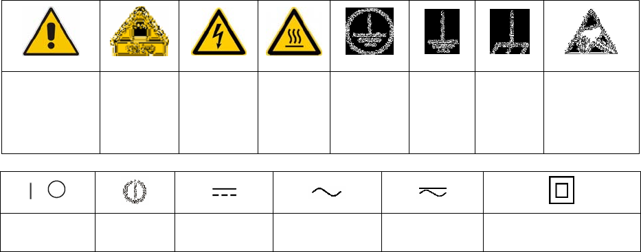
Symbols and safety labels
Notice, general
danger location
Observe product
documentation
Caution
when
handling
heavy
equipment
Danger of
electric
shock
Warning!
Hot surface
PE terminal Ground Ground
terminal
Be careful when
handling
electrostatic
sensitive
devices
ON/OFF supply
voltage
Standby
indication
Direct current
(DC)
Alternating current
(AC)
Direct/alternating
current (DC/AC)
Device fully protected by
double (reinforced) insulation

Basic Safety Instructions
1171.0000.42-05.00 Page 2
Tags and their meaning
The following signal words are used in the product documentation in order to warn the reader about risks
and dangers.
indicates a hazardous situation which, if not avoided, will result in death or
serious injury.
indicates a hazardous situation which, if not avoided, could result in death or
serious injury.
indicates a hazardous situation which, if not avoided, could result in minor or
moderate injury.
indicates the possibility of incorrect operation which can result in damage to
the product.
In the product documentation, the word ATTENTION is used synonymously.
These tags are in accordance with the standard definition for civil applications in the European Economic
Area. Definitions that deviate from the standard definition may also exist in other economic areas or
military applications. It is therefore essential to make sure that the tags described here are always used
only in connection with the related product documentation and the related product. The use of tags in
connection with unrelated products or documentation can result in misinterpretation and in personal injury
or material damage.
Operating states and operating positions
The product may be operated only under the operating conditions and in the positions specified by the
manufacturer, without the product's ventilation being obstructed. If the manufacturer's specifications are
not observed, this can result in electric shock, fire and/or serious personal injury or death. Applicable local
or national safety regulations and rules for the prevention of accidents must be observed in all work
performed.
1. Unless otherwise specified, the following requirements apply to Rohde & Schwarz products:
predefined operating position is always with the housing floor facing down, IP protection 2X, pollution
severity 2, overvoltage category 2, use only indoors, max. operating altitude 2000 m above sea level,
max. transport altitude 4500 m above sea level. A tolerance of ±10 % shall apply to the nominal
voltage and ±5 % to the nominal frequency.
2. Do not place the product on surfaces, vehicles, cabinets or tables that for reasons of weight or stability
are unsuitable for this purpose. Always follow the manufacturer's installation instructions when
installing the product and fastening it to objects or structures (e.g. walls and shelves). An installation
that is not carried out as described in the product documentation could result in personal injury or
death.
3. Do not place the product on heat-generating devices such as radiators or fan heaters. The ambient
temperature must not exceed the maximum temperature specified in the product documentation or in
the data sheet. Product overheating can cause electric shock, fire and/or serious personal injury or
death.
Basic Safety Instructions
1171.0000.42-05.00 Page 3
Electrical safety
If the information on electrical safety is not observed either at all to the extent necessary, electric shock,
fire and/or serious personal injury or death may occur.
1. Prior to switching on the product, always ensure that the nominal voltage setting on the product
matches the nominal voltage of the AC supply network. If a different voltage is to be set, the power
fuse of the product may have to be changed accordingly.
2. In the case of products of safety class I with movable power cord and connector, operation is
permitted only on sockets with an earthing contact and protective earth connection.
3. Intentionally breaking the protective earth connection either in the feed line or in the product itself is
not permitted. Doing so can result in the danger of an electric shock from the product. If extension
cords or connector strips are implemented, they must be checked on a regular basis to ensure that
they are safe to use.
4. If the product does not have a power switch for disconnection from the AC supply network, the plug of
the connecting cable is regarded as the disconnecting device. In such cases, always ensure that the
power plug is easily reachable and accessible at all times (corresponding to the length of connecting
cable, approx. 2 m). Functional or electronic switches are not suitable for providing disconnection from
the AC supply network. If products without power switches are integrated into racks or systems, a
disconnecting device must be provided at the system level.
5. Never use the product if the power cable is damaged. Check the power cable on a regular basis to
ensure that it is in proper operating condition. By taking appropriate safety measures and carefully
laying the power cable, you can ensure that the cable will not be damaged and that no one can be
hurt by, for example, tripping over the cable or suffering an electric shock.
6. The product may be operated only from TN/TT supply networks fused with max. 16 A (higher fuse
only after consulting with the Rohde & Schwarz group of companies).
7. Do not insert the plug into sockets that are dusty or dirty. Insert the plug firmly and all the way into the
socket. Otherwise, sparks that result in fire and/or injuries may occur.
8. Do not overload any sockets, extension cords or connector strips; doing so can cause fire or electric
shocks.
9. For measurements in circuits with voltages Vrms > 30 V, suitable measures (e.g. appropriate
measuring equipment, fusing, current limiting, electrical separation, insulation) should be taken to
avoid any hazards.
10. Ensure that the connections with information technology equipment, e.g. PCs or other industrial
computers, comply with the IEC60950-1/EN60950-1 or IEC61010-1/EN 61010-1 standards that apply
in each case.
11. Unless expressly permitted, never remove the cover or any part of the housing while the product is in
operation. Doing so will expose circuits and components and can lead to injuries, fire or damage to the
product.
12. If a product is to be permanently installed, the connection between the PE terminal on site and the
product's PE conductor must be made first before any other connection is made. The product may be
installed and connected only by a licensed electrician.
13. For permanently installed equipment without built-in fuses, circuit breakers or similar protective
devices, the supply circuit must be fused in such a way that anyone who has access to the product, as
well as the product itself, is adequately protected from injury or damage.
Basic Safety Instructions
1171.0000.42-05.00 Page 4
14. Use suitable overvoltage protection to ensure that no overvoltage (such as that caused by a bolt of
lightning) can reach the product. Otherwise, the person operating the product will be exposed to the
danger of an electric shock.
15. Any object that is not designed to be placed in the openings of the housing must not be used for this
purpose. Doing so can cause short circuits inside the product and/or electric shocks, fire or injuries.
16. Unless specified otherwise, products are not liquid-proof (see also section "Operating states and
operating positions", item 1. Therefore, the equipment must be protected against penetration by
liquids. If the necessary precautions are not taken, the user may suffer electric shock or the product
itself may be damaged, which can also lead to personal injury.
17. Never use the product under conditions in which condensation has formed or can form in or on the
product, e.g. if the product has been moved from a cold to a warm environment. Penetration by water
increases the risk of electric shock.
18. Prior to cleaning the product, disconnect it completely from the power supply (e.g. AC supply network
or battery). Use a soft, non-linting cloth to clean the product. Never use chemical cleaning agents such
as alcohol, acetone or diluents for cellulose lacquers.
Operation
1. Operating the products requires special training and intense concentration. Make sure that persons
who use the products are physically, mentally and emotionally fit enough to do so; otherwise, injuries
or material damage may occur. It is the responsibility of the employer/operator to select suitable
personnel for operating the products.
2. Before you move or transport the product, read and observe the section titled "Transport".
3. As with all industrially manufactured goods, the use of substances that induce an allergic reaction
(allergens) such as nickel cannot be generally excluded. If you develop an allergic reaction (such as a
skin rash, frequent sneezing, red eyes or respiratory difficulties) when using a Rohde & Schwarz
product, consult a physician immediately to determine the cause and to prevent health problems or
stress.
4. Before you start processing the product mechanically and/or thermally, or before you take it apart, be
sure to read and pay special attention to the section titled "Waste disposal", item 1.
5. Depending on the function, certain products such as RF radio equipment can produce an elevated
level of electromagnetic radiation. Considering that unborn babies require increased protection,
pregnant women must be protected by appropriate measures. Persons with pacemakers may also be
exposed to risks from electromagnetic radiation. The employer/operator must evaluate workplaces
where there is a special risk of exposure to radiation and, if necessary, take measures to avert the
potential danger.
6. Should a fire occur, the product may release hazardous substances (gases, fluids, etc.) that can
cause health problems. Therefore, suitable measures must be taken, e.g. protective masks and
protective clothing must be worn.
7. If a laser product (e.g. a CD/DVD drive) is integrated into a Rohde & Schwarz product, absolutely no
other settings or functions may be used as described in the product documentation. The objective is to
prevent personal injury (e.g. due to laser beams).
Basic Safety Instructions
1171.0000.42-05.00 Page 5
Repair and service
1. The product may be opened only by authorized, specially trained personnel. Before any work is
performed on the product or before the product is opened, it must be disconnected from the AC supply
network. Otherwise, personnel will be exposed to the risk of an electric shock.
2. Adjustments, replacement of parts, maintenance and repair may be performed only by electrical
experts authorized by Rohde & Schwarz. Only original parts may be used for replacing parts relevant
to safety (e.g. power switches, power transformers, fuses). A safety test must always be performed
after parts relevant to safety have been replaced (visual inspection, PE conductor test, insulation
resistance measurement, leakage current measurement, functional test). This helps ensure the
continued safety of the product.
Batteries and rechargeable batteries/cells
If the information regarding batteries and rechargeable batteries/cells is not observed either at all or to the
extent necessary, product users may be exposed to the risk of explosions, fire and/or serious personal
injury, and, in some cases, death. Batteries and rechargeable batteries with alkaline electrolytes (e.g.
lithium cells) must be handled in accordance with the EN 62133 standard.
1. Cells must not be taken apart or crushed.
2. Cells or batteries must not be exposed to heat or fire. Storage in direct sunlight must be avoided.
Keep cells and batteries clean and dry. Clean soiled connectors using a dry, clean cloth.
3. Cells or batteries must not be short-circuited. Cells or batteries must not be stored in a box or in a
drawer where they can short-circuit each other, or where they can be short-circuited by other
conductive materials. Cells and batteries must not be removed from their original packaging until they
are ready to be used.
4. Keep cells and batteries out of the hands of children. If a cell or a battery has been swallowed, seek
medical aid immediately.
5. Cells and batteries must not be exposed to any mechanical shocks that are stronger than permitted.
6. If a cell develops a leak, the fluid must not be allowed to come into contact with the skin or eyes. If
contact occurs, wash the affected area with plenty of water and seek medical aid.
7. Improperly replacing or charging cells or batteries that contain alkaline electrolytes (e.g. lithium cells)
can cause explosions. Replace cells or batteries only with the matching Rohde & Schwarz type (see
parts list) in order to ensure the safety of the product.
8. Cells and batteries must be recycled and kept separate from residual waste. Rechargeable batteries
and normal batteries that contain lead, mercury or cadmium are hazardous waste. Observe the
national regulations regarding waste disposal and recycling.
Transport
1. The product may be very heavy. Therefore, the product must be handled with care. In some cases,
the user may require a suitable means of lifting or moving the product (e.g. with a lift-truck) to avoid
back or other physical injuries.
Informaciones elementales de seguridad
1171.0000.42-05.00 Page 6
2. Handles on the products are designed exclusively to enable personnel to transport the product. It is
therefore not permissible to use handles to fasten the product to or on transport equipment such as
cranes, fork lifts, wagons, etc. The user is responsible for securely fastening the products to or on the
means of transport or lifting. Observe the safety regulations of the manufacturer of the means of
transport or lifting. Noncompliance can result in personal injury or material damage.
3. If you use the product in a vehicle, it is the sole responsibility of the driver to drive the vehicle safely
and properly. The manufacturer assumes no responsibility for accidents or collisions. Never use the
product in a moving vehicle if doing so could distract the driver of the vehicle. Adequately secure the
product in the vehicle to prevent injuries or other damage in the event of an accident.
Waste disposal
1. If products or their components are mechanically and/or thermally processed in a manner that goes
beyond their intended use, hazardous substances (heavy-metal dust such as lead, beryllium, nickel)
may be released. For this reason, the product may only be disassembled by specially trained
personnel. Improper disassembly may be hazardous to your health. National waste disposal
regulations must be observed.
2. If handling the product releases hazardous substances or fuels that must be disposed of in a special
way, e.g. coolants or engine oils that must be replenished regularly, the safety instructions of the
manufacturer of the hazardous substances or fuels and the applicable regional waste disposal
regulations must be observed. Also observe the relevant safety instructions in the product
documentation. The improper disposal of hazardous substances or fuels can cause health problems
and lead to environmental damage.
Informaciones elementales de seguridad
Es imprescindible leer y observar las siguientes instrucciones e informaciones de seguridad!
El principio del grupo de empresas Rohde & Schwarz consiste en tener nuestros productos siempre al día
con los estándares de seguridad y de ofrecer a nuestros clientes el máximo grado de seguridad. Nuestros
productos y todos los equipos adicionales son siempre fabricados y examinados según las normas de
seguridad vigentes. Nuestro sistema de garantía de calidad controla constantemente que sean cumplidas
estas normas. El presente producto ha sido fabricado y examinado según el certificado de conformidad
adjunto de la UE y ha salido de nuestra planta en estado impecable según los estándares técnicos de
seguridad. Para poder preservar este estado y garantizar un funcionamiento libre de peligros, el usuario
deberá atenerse a todas las indicaciones, informaciones de seguridad y notas de alerta. El grupo de
empresas Rohde & Schwarz está siempre a su disposición en caso de que tengan preguntas referentes a
estas informaciones de seguridad.
Además queda en la responsabilidad del usuario utilizar el producto en la forma debida. Este producto
está destinado exclusivamente al uso en la industria y el laboratorio o, si ha sido expresamente
autorizado, para aplicaciones de campo y de ninguna manera deberá ser utilizado de modo que alguna
persona/cosa pueda sufrir daño. El uso del producto fuera de sus fines definidos o sin tener en cuenta las
instrucciones del fabricante queda en la responsabilidad del usuario. El fabricante no se hace en ninguna
forma responsable de consecuencias a causa del mal uso del producto.
Informaciones elementales de seguridad
1171.0000.42-05.00 Page 7
Se parte del uso correcto del producto para los fines definidos si el producto es utilizado conforme a las
indicaciones de la correspondiente documentación del producto y dentro del margen de rendimiento
definido (ver hoja de datos, documentación, informaciones de seguridad que siguen). El uso del producto
hace necesarios conocimientos técnicos y ciertos conocimientos del idioma inglés. Por eso se debe tener
en cuenta que el producto solo pueda ser operado por personal especializado o personas instruidas en
profundidad con las capacidades correspondientes. Si fuera necesaria indumentaria de seguridad para el
uso de productos de Rohde & Schwarz, encontraría la información debida en la documentación del
producto en el capítulo correspondiente. Guarde bien las informaciones de seguridad elementales, así
como la documentación del producto, y entréguelas a usuarios posteriores.
Tener en cuenta las informaciones de seguridad sirve para evitar en lo posible lesiones o daños por
peligros de toda clase. Por eso es imprescindible leer detalladamente y comprender por completo las
siguientes informaciones de seguridad antes de usar el producto, y respetarlas durante el uso del
producto. Deberán tenerse en cuenta todas las demás informaciones de seguridad, como p. ej. las
referentes a la protección de personas, que encontrarán en el capítulo correspondiente de la
documentación del producto y que también son de obligado cumplimiento. En las presentes
informaciones de seguridad se recogen todos los objetos que distribuye el grupo de empresas
Rohde & Schwarz bajo la denominación de "producto", entre ellos también aparatos, instalaciones así
como toda clase de accesorios.
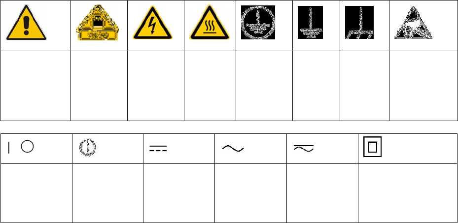
Símbolos y definiciones de seguridad
Aviso: punto de
peligro general
Observar la
documentación
del producto
Atención en
el manejo de
dispositivos
de peso
elevado
Peligro de
choque
eléctrico
Adver-
tencia:
superficie
caliente
Conexión a
conductor de
protección
Conexión
atierra
Conexión
amasa
Aviso: Cuidado
en el manejo de
dispositivos
sensibles a la
electrostática
(ESD)
Tensión de
alimentación de
PUESTA EN
MARCHA /
PARADA
Indicación de
estado de
espera
(Standby)
Corriente
continua (DC)
Corriente alterna
(AC)
Corriente
continua /
Corriente alterna
(DC/AC)
El aparato está protegido
en su totalidad por un
aislamiento doble
(reforzado)

Informaciones elementales de seguridad
1171.0000.42-05.00 Page 8
Palabras de señal y su significado
En la documentación del producto se utilizan las siguientes palabras de señal con el fin de advertir contra
riesgos y peligros.
PELIGRO identifica un peligro inminente con riesgo elevado que
provocará muerte o lesiones graves si no se evita.
ADVERTENCIA identifica un posible peligro con riesgo medio de
provocar muerte o lesiones (graves) si no se evita.
ATENCIÓN identifica un peligro con riesgo reducido de provocar
lesiones leves o moderadas si no se evita.
AVISO indica la posibilidad de utilizar mal el producto y, como
consecuencia, dañarlo.
En la documentación del producto se emplea de forma sinónima el
término CUIDADO.
Las palabras de señal corresponden a la definición habitual para aplicaciones civiles en el área
económica europea. Pueden existir definiciones diferentes a esta definición en otras áreas económicas o
en aplicaciones militares. Por eso se deberá tener en cuenta que las palabras de señal aquí descritas
sean utilizadas siempre solamente en combinación con la correspondiente documentación del producto y
solamente en combinación con el producto correspondiente. La utilización de las palabras de señal en
combinación con productos o documentaciones que no les correspondan puede llevar a interpretaciones
equivocadas y tener por consecuencia daños en personas u objetos.
Estados operativos y posiciones de funcionamiento
El producto solamente debe ser utilizado según lo indicado por el fabricante respecto a los estados
operativos y posiciones de funcionamiento sin que se obstruya la ventilación. Si no se siguen las
indicaciones del fabricante, pueden producirse choques eléctricos, incendios y/o lesiones graves con
posible consecuencia de muerte. En todos los trabajos deberán ser tenidas en cuenta las normas
nacionales y locales de seguridad del trabajo y de prevención de accidentes.
1. Si no se convino de otra manera, es para los productos Rohde & Schwarz válido lo que sigue:
como posición de funcionamiento se define por principio la posición con el suelo de la caja para
abajo, modo de protección IP 2X, grado de suciedad 2, categoría de sobrecarga eléctrica 2, uso
solamente en estancias interiores, utilización hasta 2000 m sobre el nivel del mar, transporte hasta
4500 m sobre el nivel del mar. Se aplicará una tolerancia de ±10 % sobre el voltaje nominal y de
±5 % sobre la frecuencia nominal.
2. No sitúe el producto encima de superficies, vehículos, estantes o mesas, que por sus características
de peso o de estabilidad no sean aptos para él. Siga siempre las instrucciones de instalación del
fabricante cuando instale y asegure el producto en objetos o estructuras (p. ej. paredes y estantes). Si
se realiza la instalación de modo distinto al indicado en la documentación del producto, pueden
causarse lesiones o incluso la muerte.
3. No ponga el producto sobre aparatos que generen calor (p. ej. radiadores o calefactores). La
temperatura ambiente no debe superar la temperatura máxima especificada en la documentación del
producto o en la hoja de datos. En caso de sobrecalentamiento del producto, pueden producirse
choques eléctricos, incendios y/o lesiones graves con posible consecuencia de muerte.
Informaciones elementales de seguridad
1171.0000.42-05.00 Page 9
Seguridad eléctrica
Si no se siguen (o se siguen de modo insuficiente) las indicaciones del fabricante en cuanto a seguridad
eléctrica, pueden producirse choques eléctricos, incendios y/o lesiones graves con posible consecuencia
de muerte.
1. Antes de la puesta en marcha del producto se deberá comprobar siempre que la tensión
preseleccionada en el producto coincida con la de la red de alimentación eléctrica. Si es necesario
modificar el ajuste de tensión, también se deberán cambiar en caso dado los fusibles
correspondientes del producto.
2. Los productos de la clase de protección I con alimentación móvil y enchufe individual solamente
podrán enchufarse a tomas de corriente con contacto de seguridad y con conductor de protección
conectado.
3. Queda prohibida la interrupción intencionada del conductor de protección, tanto en la toma de
corriente como en el mismo producto. La interrupción puede tener como consecuencia el riesgo de
que el producto sea fuente de choques eléctricos. Si se utilizan cables alargadores o regletas de
enchufe, deberá garantizarse la realización de un examen regular de los mismos en cuanto a su
estado técnico de seguridad.
4. Si el producto no está equipado con un interruptor para desconectarlo de la red, se deberá considerar
el enchufe del cable de conexión como interruptor. En estos casos se deberá asegurar que el enchufe
siempre sea de fácil acceso (de acuerdo con la longitud del cable de conexión, aproximadamente
2m). Los interruptores de función o electrónicos no son aptos para el corte de la red eléctrica. Si los
productos sin interruptor están integrados en bastidores o instalaciones, se deberá colocar el
interruptor en el nivel de la instalación.
5. No utilice nunca el producto si está dañado el cable de conexión a red. Compruebe regularmente el
correcto estado de los cables de conexión a red. Asegúrese, mediante las medidas de protección y
de instalación adecuadas, de que el cable de conexión a red no pueda ser dañado o de que nadie
pueda ser dañado por él, p. ej. al tropezar o por un choque eléctrico.
6. Solamente está permitido el funcionamiento en redes de alimentación TN/TT aseguradas con fusibles
de 16 A como máximo (utilización de fusibles de mayor amperaje solo previa consulta con el grupo de
empresas Rohde & Schwarz).
7. Nunca conecte el enchufe en tomas de corriente sucias o llenas de polvo. Introduzca el enchufe por
completo y fuertemente en la toma de corriente. La no observación de estas medidas puede provocar
chispas, fuego y/o lesiones.
8. No sobrecargue las tomas de corriente, los cables alargadores o las regletas de enchufe ya que esto
podría causar fuego o choques eléctricos.
9. En las mediciones en circuitos de corriente con una tensión Ueff > 30 V se deberán tomar las medidas
apropiadas para impedir cualquier peligro (p. ej. medios de medición adecuados, seguros, limitación
de tensión, corte protector, aislamiento etc.).
10. Para la conexión con dispositivos informáticos como un PC o un ordenador industrial, debe
comprobarse que éstos cumplan los estándares IEC60950-1/EN60950-1 o IEC61010-1/EN 61010-1
válidos en cada caso.
11. A menos que esté permitido expresamente, no retire nunca la tapa ni componentes de la carcasa
mientras el producto esté en servicio. Esto pone a descubierto los cables y componentes eléctricos y
puede causar lesiones, fuego o daños en el producto.
Informaciones elementales de seguridad
1171.0000.42-05.00 Page 10
12. Si un producto se instala en un lugar fijo, se deberá primero conectar el conductor de protección fijo
con el conductor de protección del producto antes de hacer cualquier otra conexión. La instalación y
la conexión deberán ser efectuadas por un electricista especializado.
13. En el caso de dispositivos fijos que no estén provistos de fusibles, interruptor automático ni otros
mecanismos de seguridad similares, el circuito de alimentación debe estar protegido de modo que
todas las personas que puedan acceder al producto, así como el producto mismo, estén a salvo de
posibles daños.
14. Todo producto debe estar protegido contra sobretensión (debida p. ej. a una caída del rayo) mediante
los correspondientes sistemas de protección. Si no, el personal que lo utilice quedará expuesto al
peligro de choque eléctrico.
15. No debe introducirse en los orificios de la caja del aparato ningún objeto que no esté destinado a ello.
Esto puede producir cortocircuitos en el producto y/o puede causar choques eléctricos, fuego o
lesiones.
16. Salvo indicación contraria, los productos no están impermeabilizados (ver también el capítulo
"Estados operativos y posiciones de funcionamiento", punto 1). Por eso es necesario tomar las
medidas necesarias para evitar la entrada de líquidos. En caso contrario, existe peligro de choque
eléctrico para el usuario o de daños en el producto, que también pueden redundar en peligro para las
personas.
17. No utilice el producto en condiciones en las que pueda producirse o ya se hayan producido
condensaciones sobre el producto o en el interior de éste, como p. ej. al desplazarlo de un lugar frío a
otro caliente. La entrada de agua aumenta el riesgo de choque eléctrico.
18. Antes de la limpieza, desconecte por completo el producto de la alimentación de tensión (p. ej. red de
alimentación o batería). Realice la limpieza de los aparatos con un paño suave, que no se deshilache.
No utilice bajo ningún concepto productos de limpieza químicos como alcohol, acetona o diluyentes
para lacas nitrocelulósicas.
Funcionamiento
1. El uso del producto requiere instrucciones especiales y una alta concentración durante el manejo.
Debe asegurarse que las personas que manejen el producto estén a la altura de los requerimientos
necesarios en cuanto a aptitudes físicas, psíquicas y emocionales, ya que de otra manera no se
pueden excluir lesiones o daños de objetos. El empresario u operador es responsable de seleccionar
el personal usuario apto para el manejo del producto.
2. Antes de desplazar o transportar el producto, lea y tenga en cuenta el capítulo "Transporte".
3. Como con todo producto de fabricación industrial no puede quedar excluida en general la posibilidad
de que se produzcan alergias provocadas por algunos materiales empleados, los llamados alérgenos
(p. ej. el níquel). Si durante el manejo de productos Rohde & Schwarz se producen reacciones
alérgicas, como p. ej. irritaciones cutáneas, estornudos continuos, enrojecimiento de la conjuntiva o
dificultades respiratorias, debe avisarse inmediatamente a un médico para investigar las causas y
evitar cualquier molestia o daño a la salud.
4. Antes de la manipulación mecánica y/o térmica o el desmontaje del producto, debe tenerse en cuenta
imprescindiblemente el capítulo "Eliminación", punto 1.
Informaciones elementales de seguridad
1171.0000.42-05.00 Page 11
5. Ciertos productos, como p. ej. las instalaciones de radiocomunicación RF, pueden a causa de su
función natural, emitir una radiación electromagnética aumentada. Deben tomarse todas las medidas
necesarias para la protección de las mujeres embarazadas. También las personas con marcapasos
pueden correr peligro a causa de la radiación electromagnética. El empresario/operador tiene la
obligación de evaluar y señalizar las áreas de trabajo en las que exista un riesgo elevado de
exposición a radiaciones.
6. Tenga en cuenta que en caso de incendio pueden desprenderse del producto sustancias tóxicas
(gases, líquidos etc.) que pueden generar daños a la salud. Por eso, en caso de incendio deben
usarse medidas adecuadas, como p. ej. máscaras antigás e indumentaria de protección.
7. En caso de que un producto Rohde & Schwarz contenga un producto láser (p. ej. un lector de
CD/DVD), no debe usarse ninguna otra configuración o función aparte de las descritas en la
documentación del producto, a fin de evitar lesiones (p. ej. debidas a irradiación láser).
Reparación y mantenimiento
1. El producto solamente debe ser abierto por personal especializado con autorización para ello. Antes
de manipular el producto o abrirlo, es obligatorio desconectarlo de la tensión de alimentación, para
evitar toda posibilidad de choque eléctrico.
2. El ajuste, el cambio de partes, el mantenimiento y la reparación deberán ser efectuadas solamente
por electricistas autorizados por Rohde & Schwarz. Si se reponen partes con importancia para los
aspectos de seguridad (p. ej. el enchufe, los transformadores o los fusibles), solamente podrán ser
sustituidos por partes originales. Después de cada cambio de partes relevantes para la seguridad
deberá realizarse un control de seguridad (control a primera vista, control del conductor de
protección, medición de resistencia de aislamiento, medición de la corriente de fuga, control de
funcionamiento). Con esto queda garantizada la seguridad del producto.
Baterías y acumuladores o celdas
Si no se siguen (o se siguen de modo insuficiente) las indicaciones en cuanto a las baterías y
acumuladores o celdas, pueden producirse explosiones, incendios y/o lesiones graves con posible
consecuencia de muerte. El manejo de baterías y acumuladores con electrolitos alcalinos (p. ej. celdas de
litio) debe seguir el estándar EN 62133.
1. No deben desmontarse, abrirse ni triturarse las celdas.
2. Las celdas o baterías no deben someterse a calor ni fuego. Debe evitarse el almacenamiento a la luz
directa del sol. Las celdas y baterías deben mantenerse limpias y secas. Limpiar las conexiones
sucias con un paño seco y limpio.
3. Las celdas o baterías no deben cortocircuitarse. Es peligroso almacenar las celdas o baterías en
estuches o cajones en cuyo interior puedan cortocircuitarse por contacto recíproco o por contacto con
otros materiales conductores. No deben extraerse las celdas o baterías de sus embalajes originales
hasta el momento en que vayan a utilizarse.
4. Mantener baterías y celdas fuera del alcance de los niños. En caso de ingestión de una celda o
batería, avisar inmediatamente a un médico.
5. Las celdas o baterías no deben someterse a impactos mecánicos fuertes indebidos.
Informaciones elementales de seguridad
1171.0000.42-05.00 Page 12
6. En caso de falta de estanqueidad de una celda, el líquido vertido no debe entrar en contacto con la
piel ni los ojos. Si se produce contacto, lavar con agua abundante la zona afectada y avisar a un
médico.
7. En caso de cambio o recarga inadecuados, las celdas o baterías que contienen electrolitos alcalinos
(p. ej. las celdas de litio) pueden explotar. Para garantizar la seguridad del producto, las celdas o
baterías solo deben ser sustituidas por el tipo Rohde & Schwarz correspondiente (ver lista de
recambios).
8. Las baterías y celdas deben reciclarse y no deben tirarse a la basura doméstica. Las baterías o
acumuladores que contienen plomo, mercurio o cadmio deben tratarse como residuos especiales.
Respete en esta relación las normas nacionales de eliminación y reciclaje.
Transporte
1. El producto puede tener un peso elevado. Por eso es necesario desplazarlo o transportarlo con
precaución y, si es necesario, usando un sistema de elevación adecuado (p. ej. una carretilla
elevadora), a fin de evitar lesiones en la espalda u otros daños personales.
2. Las asas instaladas en los productos sirven solamente de ayuda para el transporte del producto por
personas. Por eso no está permitido utilizar las asas para la sujeción en o sobre medios de transporte
como p. ej. grúas, carretillas elevadoras de horquilla, carros etc. Es responsabilidad suya fijar los
productos de manera segura a los medios de transporte o elevación. Para evitar daños personales o
daños en el producto, siga las instrucciones de seguridad del fabricante del medio de transporte o
elevación utilizado.
3. Si se utiliza el producto dentro de un vehículo, recae de manera exclusiva en el conductor la
responsabilidad de conducir el vehículo de manera segura y adecuada. El fabricante no asumirá
ninguna responsabilidad por accidentes o colisiones. No utilice nunca el producto dentro de un
vehículo en movimiento si esto pudiera distraer al conductor. Asegure el producto dentro del vehículo
debidamente para evitar, en caso de un accidente, lesiones u otra clase de daños.
Eliminación
1. Si se trabaja de manera mecánica y/o térmica cualquier producto o componente más allá del
funcionamiento previsto, pueden liberarse sustancias peligrosas (polvos con contenido de metales
pesados como p. ej. plomo, berilio o níquel). Por eso el producto solo debe ser desmontado por
personal especializado con formación adecuada. Un desmontaje inadecuado puede ocasionar daños
para la salud. Se deben tener en cuenta las directivas nacionales referentes a la eliminación de
residuos.
2. En caso de que durante el trato del producto se formen sustancias peligrosas o combustibles que
deban tratarse como residuos especiales (p. ej. refrigerantes o aceites de motor con intervalos de
cambio definidos), deben tenerse en cuenta las indicaciones de seguridad del fabricante de dichas
sustancias y las normas regionales de eliminación de residuos. Tenga en cuenta también en caso
necesario las indicaciones de seguridad especiales contenidas en la documentación del producto. La
eliminación incorrecta de sustancias peligrosas o combustibles puede causar daños a la salud o
daños al medio ambiente.

Chapter 1 Safety Instructions
2098.1190.72 - 1.4 - E-4
4 Special Danger Warnings
4.1 Hazards due to AC Supply Voltage
There is a risk of electric shock with any Vrms > 30 V AC or V > 60 V DC voltage. Appropri-
ate measures must be taken to prevent exposure to any danger when working with voltages
that bear the risk of electric shock. Never work on live parts unless specifically required and
only if the special safety precautions are complied with.
4.1.1 AC Power Supply
Before connecting the AC power supply, it is important to ensure that the power supply
specifications given for the system or instruments match the nominal specifications for
the local power supply network. The power supply circuit must be protected by means
of fuses in order to prevent overloads and short-circuits.
Miniature modules have neutral conductor fuses. As a result, the power supply may still
be connected even after interruption of the circuit by a fuse.
It is quite possible for a transmitter to have several separate electric circuits. Each of these
circuits is subject to the following requirements:
All electrical connections between the transmitter and the AC power supply must comply
with the following conditions:
– The transmitter can be disconnected at any time.
– The transmitter can be prevented from being switched back on.
– The transmitter is terminated with a fully protected power cable matched to the power
consumption.1
– Ensure that phase rotation is correct (direction of rotation of fans!).
Service sockets
It is common practice to equip transmitters with a connector that carries voltage even when
the transmitter is turned off and that allows power to be supplied to test equipment or a sol-
dering iron. These connectors are identified, e.g. by an LED, and may only be used for the
aforementioned purposes.
The intended purpose of the sockets means that they have only a limited power output. The
connector is not suitable for supplying power to heating equipment or large test sets.
The transmitter operator is responsible for providing the correct fuse protection (the
maximum value is specified on the socket).
In the case of accessory parts that are not connected to the main transmitter, the trans-
mitter operator is responsible for taking appropriate measures to ensure that the instal-
lation is safe in the respective switching state.
1 Obtain the specifications from this documentation and also adhere to the breaking capacity limits of the fuses
and circuit breakers in the transmitter.

Chapter 1 Safety Instructions
2098.1190.72 - 1.5 - E-4
4.1.2 Replacing Fuses
Replace the safety fuses accessible in the operator area only if no voltage is being ap-
plied to the instruments. The safety fuses may be replaced only by fuses with identical
electric data, identical switching characteristics and identical switch-off capacity.
Motor and line circuit breakers accessible in the transmitter's operator area may be op-
erated. If their response range is selectable, do not change the settings made by the
manufacturer. If the settings are accidentally changed, reset them by using the correct
values specified in this documentation.
4.1.3 Emergency-Off Equipment
If the customer requests, the transmitters are equipped with emergency keys. When the
transmitters are supplied, these keys have basically no function. The transmitter opera-
tor is responsible for ensuring that these emergency keys function safely and to inte-
grate them into the emergency-off system of the operator area in accordance with the
regulations. If you subsequently decide not to use the emergency keys as an emergen-
cy-off system, you must remove them.
Extremely important! A transmitter normally has several AC supply circuits that are
independent from each other, such as main AC supply circuit, AC current supply for ac-
cessory equipment (main control unit, antenna switch, etc) or AC current supply for a
disabled socket.
The transmitter operator is responsible for making sure that all these circuits are inte-
grated correctly into the emergency-off system. Circuits not integrated have to be la-
beled accordingly.
Never set up a transmitter that is equipped with disabled emergency-off equipment.
4.1.4 Opening the Transmitter
When you open the transmitter to carry out mechanical/electrical tasks (e.g. cleaning,
repair, etc) always follow the five basic rules for working with electrical systems:
– Disconnect the transmitter from the power supply
– Secure it against inadvertent switch-on
– Verify safe isolation from any power
– Ground or short-circuit it2
– Cover adjacent active circuits.
Extremely important! A transmitter normally has several AC supply circuits that are in-
dependent from each other, such as main AC supply circuit, AC current supply for ac-
cessory equipment (main control unit, antenna switch, etc) or AC current supply for a
disabled socket.
Prior to performing any work, check the current status of the circuits. Also disconnect
adjacent circuits to prevent inadvertent contact.
2 Not all transmitter types can be grounded or short-circuited by using a grounding or short-circuit switch. If a
suitable device for grounding or short-circuiting is not available, the skilled personnel must take appropriate
measures as deemed necessary.

Chapter 1 Safety Instructions
2098.1190.72 - 1.6 - E-4
If you have to perform any work on the RF circuit, isolate the antenna connector as well.
Caution! If other transmitters, etc, are in operation that are coupled to the same antenna
via RF filters, energy from them can be fed back via the antenna cable.
Never open a disconnected transmitter without taking protective measures against
touching voltage-carrying parts.
Due to the risk of electric shock from the AC supply voltage, never perform any electrical
operations when doors are open, front panels are unscrewed, plug-ins are withdrawn,
etc.
When electrical operations of the transmitter are performed for the purpose of internal
measurements or repair, label the workplace accordingly and provide warning about the
potential hazards in accordance with the basic rules of electrical engineering.
Appropriate measures have to be taken to prevent unauthorized persons from access-
ing this area.
After completing your work, close the transmitter and restore all safety measures for pre-
venting electric shock that have been provided by the manufacturer. Immediately make
sure that protective equipment (e.g. locks) is effective.
4.2 Hazards due to High-Energy Circuits
The instruments include low-voltage circuits which can be fed from an extremely low-imped-
ance voltage source(e.g. amplifier operating voltage). These circuits conduct dangerously
large amounts of energy. We handle these circuits in the same manner as circuits with volt-
ages that bear the risk of electric shock. They are usually covered and thus protected
against accidental contact. The cover comes with a warning label.
If you remove the cover of a transmitter that is in operation, there is the risk of both voltage
poles being short-circuited. Short circuits create an electric arc and thus can cause burns,
damage to the eyes as well as further injuries due to the state of shock response.
Practical experience has repeatedly shown that a short circuit caused by metal tools can
cause severe burns. For safety reasons, high-energy circuits are protected by covers and
are thus not accessible within the operator area of the instruments.
If you need to measure low-impedance voltages, during repair work or to optimize the
power consumption of the transmitter for example, exercise the same caution as when
measuring operating voltages that bear the risk of electric shock.
Wear protective clothing if necessary.
Before you open an instrument or remove its cover, switch off the operating voltage and
wait for five minutes to ensure that any and all capacitors are sufficiently discharged.
Do not short-ciruit capacitors to discharge them.
4.3 RF Hazards
4.3.1 Mandatory Training
Operators must instruct their personnel on how to use this transmitter or instrument in
accordance with EN 60215 and IEC 215. This periodic training must cover the radio-fre-

Chapter 1 Safety Instructions
2098.1190.72 - 1.7 - E-4
quency hazards of the individual transmitter or instrument. Only after such training has
been provided and documented may the operating personnel handle switching and op-
erating tasks.
High-energy RF circuits within the transmitter or the instrument are routed via conventional
detachable RF connectors (e.g. N). Depending on the output power, the transmitter or in-
strument outputs come with screw-in or pluggable RF lines or ducts.
If RF lines or modules conduct high power, the connection point or the entire module is
marked with the standard warning symbol (yellow triangle with black exclamation mark).
4.3.2 RF Shielding
Transmitters and instruments from Rohde & Schwarz are shielded in such a manner that
RF radiation does not pose any danger even in the immediate vicinity if all RF lines are
closed. This statement is based on the ordinance for electromagnetic fields as defined in
German law:
The 26th ordinance for the Federal Emission Protection Law dated December 16, 1996 de-
fines limit values for radio-frequency equipment for electric and magnetic field strengths.
4.3.3 Rules for Operating the Transmitter
Opening RF lines during operation may cause electric arcs. This can cause burns and eye
injuries.
Operate the transmitter system only if an antenna or dummy antenna is connected.
Never undo RF lines during transmitter operation.
Never open modules during transmitter operation.
Never put transmitters into operation if RF lines are open. 3
When disconnecting a transmitter, always disconnect the antenna connector as well. If
other transmitters, etc, are in operation that are coupled to the same antenna via RF fil-
ters, energy from them can be fed back via the antenna cable.
4.3.4 Rules for Working with an Open Transmitter
If you switch on an open transmitter and remove covers and shielding that carry the general
warning symbol of RF modules, dangerous RF levels will be radiated .
The transmitter operator is responsible for strict compliance with the necessary safety pre-
cautions when someone is working with or located near an open transmitter that is switched
on.
Necessary safety regulations include:
3 If you try to put the transmitter into operation, RF power is transmitted. If RF lines are open, the transmitter
switches off the RF again. This attempt to transmit RF can lead to the above mentioned risks of injury even if
- as is the case with Rohde & Schwarz transmitters - the RF flow is limited and transient due to technical mea-
sures.

Chapter 1 Safety Instructions
2098.1190.72 - 1.8 - E-4
Labeling the workplace as subject to RF hazards
Wearing RF protective cloth
Taking special safety precautions for persons with implants such as metal parts, pace-
makers, etc, since they are particularly susceptible to injury.
4.4 Fire Hazards
Every electric circuit containing sufficient energy and to which voltage is applied poses fire
hazards. This also applies to radio transmitters. For transmitter radio systems, it is therefore
necessary to create a safety plan for the event of fire.
Operating personnel must be trained on how to proceed in the case of fire in areas contain-
ing electrical systems; training must be repeated at regular intervals. Personnel should be
trained on the basis of the VDE 0132 standard and in agreement with the local fire depart-
ment.
The following statement applies in Germany. Preventive measures at the site in question
can largely eliminate the risk of fire or prevent its spread as far as possible.
Prevention and fire-fighting
When setting up the transmitter, the operator must ensure that no inflammable materials
are located below or above the cable entry nor attached to it.
Make sure that openings to adjacent spaces are closed in a flame-retardant manner.
Fire-fighting is only allowed with special equipment even if the flames are insignificant
or have no effect at all (e.g. breathing mask with air bottle).
For fire-fighting, only suitable fire extinguishers (e.g. CO2 extinguishers) may be used.
One reason for requiring special equipment is the fact that extremely poisonous and imper-
ceptible carbon monoxide is released during every fire. Another reason is that the materials
contained in the instruments and systems emit poisonous vapors, gases and dust such as
sulfuric acid and hydrogen sulfide, hydrochloric acid, dioxin, hydrofluoric acid and beryllium
oxide dust when they are exposed to external flame and heat.
The following materials can be affected:
– Rubber in cables, cable bushings, vibration absorbers and instrument feet
– PVC in cables and lines
– PUR (foam) in insulators, molded parts, sealing mats and insulating strips
– Teflon in cables, lines, insulation material and printed boards
– Beryllium oxide ceramics in power transistors

Chapter 1 Safety Instructions
2098.1190.72 - 1.9 - E-4
5 Safety Data Sheets for Hazardous Materials
This section contains the following safety data sheets in accordance with guideline 91/155/
EEC:
– EC safety data sheet for heat-conductive paste
– EC safety data sheet for heat sink ribs HS-400

Broadcasting Division
2095.7346.32 - 2.0 - E-1
CHAPTER 2
DESIGN AND CHARACTERISTICS
Printed in Germany

Chapter 2 Design and Characteristics
2098.0188.72 - 2.01 - E-1
CONTENTS
1 Design and Function ....................................................................... 1
1.1 Power Distribution ..........................................................................................5
1.1.1 Main Switch (Power Supply Terminal) .........................................................6
1.1.2 Motor Protection Switches ............................................................................6
1.1.3 Automatic Line Fuses ...................................................................................7
1.1.4 Power Distribution Board ..............................................................................8
1.1.5 Auxiliary Power Supply Unit .........................................................................9
1.1.6 Optional Socket ..........................................................................................10
1.1.7 Grounding Bolt ...........................................................................................10
1.2 Transmitter Control Unit ..............................................................................11
1.2.1 R&S NetCCU800 ........................................................................................11
1.2.2 Rack Controller ...........................................................................................11
1.3 Connection Panel .........................................................................................13
1.4 Exciter Unit ....................................................................................................14
1.4.1 Exciter ........................................................................................................15
1.4.2 Exciter Switch .............................................................................................15
1.5 Output Stage Unit .........................................................................................15
1.5.1 Splitter ........................................................................................................17
1.5.2 Amplifier .....................................................................................................18
1.5.3 Combiner ....................................................................................................18
1.5.4 Absorber .....................................................................................................19
1.6 Directional Coupler Lightning Protection System ....................................21
1.6.1 Lightning Arrester .......................................................................................21
1.6.2 Directional Couplers ...................................................................................22
1.6.3 Directional Coupler Interface ......................................................................23
1.7 Harmonics Filter ...........................................................................................23
1.8 RF Connector ................................................................................................24
1.9 Cooling System ............................................................................................25
1.9.1 Intake/Exhaust Air Ducts ............................................................................26
1.9.2 Fans ...........................................................................................................27
1.9.3 Starting Capacitors .....................................................................................28
1.9.4 Differential Pressure Gages .......................................................................29
1.9.5 Temperature Sensors .................................................................................30

Chapter 2 Design and Characteristics
2098.0188.72 - 2.02 - E-1
2 Specifications ................................................................................ 31
2.1 Transmitter System – General .....................................................................31
2.2 Transmitter System – Specific ....................................................................32
2.2.1 R&S NV8301 ..............................................................................................32
2.2.2 R&S NV8302 ..............................................................................................33
2.2.3 R&S NV8303 ..............................................................................................33
2.2.4 R&S NV8304 ..............................................................................................34

Chapter 2 Design and Characteristics
2098.0188.72 - 2.1 - E-1
1 Design and Function
The new air-cooled R&S NV8300 transmitter family is designed for transmitting digital TV
signals in the IV and V frequency bands (UHF). Digital standards DVB-T/-H, ATSC, DTMB,
ISDB-T and MediaFLO can be transmitted.
LDMOS transistor-based amplifiers ensure high output power while requiring only minimum
space. For ATSC, output power of 500 W to 1.8 kW is available.
Both the power class of the transmitter and its type designation depend on the number of
built-in amplifiers.
This chapter describes the transmitter's design and the functions of its components.
Number of amplifiers Power
Transmitter type (R&S VH8300A1) MER 34 dB MER 33 dB a)
a) The specified output power cannot be achieved on every channel. Only n x 450 W of ATSC power is possible
up to 486 MHz.
R&S NV8301 1 430 W 500 W
R&S NV8302 2 860 W 1000 W
R&S NV8303 3 1290 W 1500 W
R&S NV8304 4 1720 W 1800 W b)
b) The output power is limited by the maximum power-handling capacity of the harmonics filter.
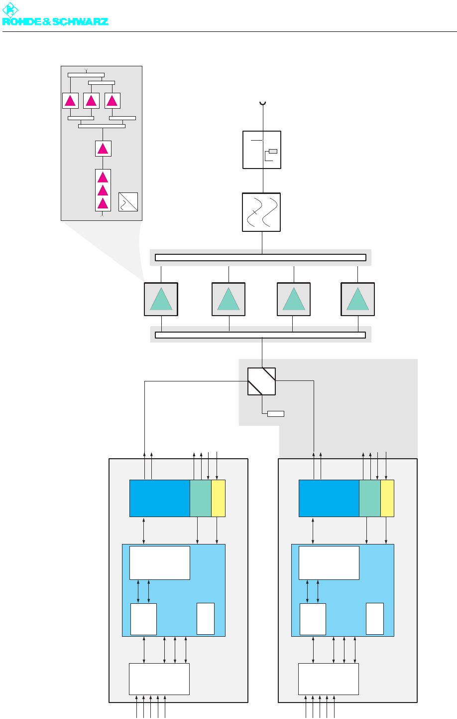
Chapter 2 Design and Characteristics
2098.0188.72 - 2.2 - E-1
Fig. 1 Block diagram of DTV transmitter; here R&S NV8304V
Exciter Standby
Amplifier
VH8300A1
=
Lightning
Protection
Measurement
Coupler
Harmonics
Filter
RF
Output
max. 6 VH8300A1
Input
Interface
DTV
TS1
TS2
TS3
TS4
Ext 1PPS
Coder
I
Q
Linear
and
nonlinear
Precorrection
Upconverter
Dig. IQ
Dig. IF
120MHz
Synthesizer
Down-
converter
PLL
Mainboard
LO Mon.
Ext. REF
10MHz Mon.
RF N
RF DTV
RF Mon.
TV Exciter SX800 A
3xTS
120MHz
Control
1pps
Input
Interface
DTV
TS1
TS2
TS3
TS4
Ext 1PPS
Coder
I
Q
Linear
and
nonlinear
Precorrection
Upconverter
Dig. IQ
Dig. IF
120MHz
Synthesizer
Down-
converter
PLL
Mainboard
LO Mon.
Ext. REF
10MHz Mon.
RF N
RF DTV
RF Mon.
TV Exciter SX800 B
3xTS
120MHz
Control
1pps
Option
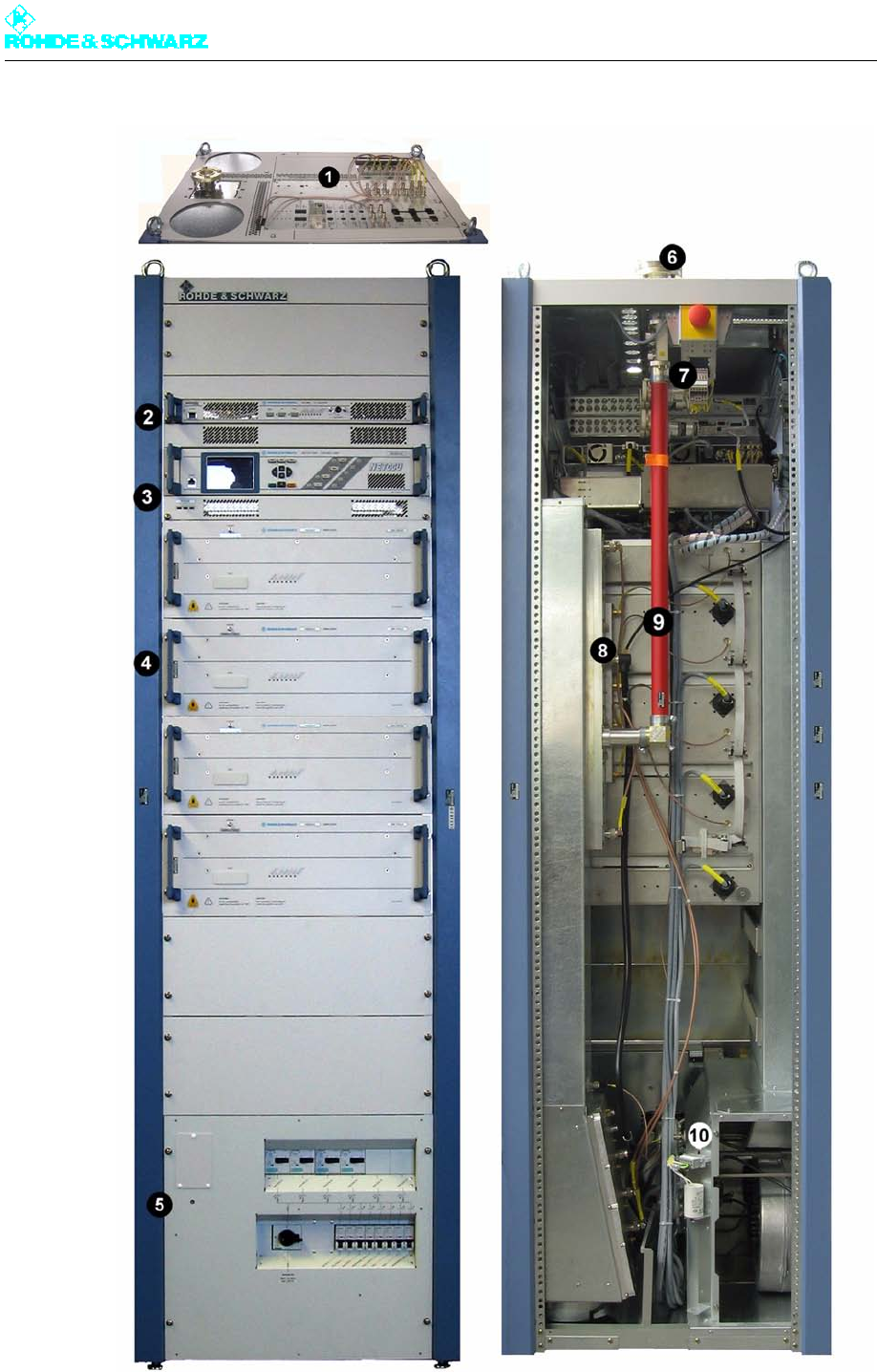
Chapter 2 Design and Characteristics
2098.0188.72 - 2.3 - E-1
Fig. 2 Modules of DTV transmitter; here R&S NV8304

Chapter 2 Design and Characteristics
2098.0188.72 - 2.4 - E-1
1) Connection panel
2) Exciter
3) Transmitter control unit
4) Output stage
5) Power distribution
6) RF connector
7) Directional coupler lightning protection system
8) Splitter/combiner unit
9) Harmonics filter
10) Intake box (fan)
The R&S NV8300 transmitter family consists of the following units and modules:
Power distribution
– Main switch
– Motor protection switches
– Automatic line fuses
– Power distribution board
– Auxiliary power supply unit
– Optional socket
– Grounding bolt
Transmitter control unit components
– R&S NetCCU800
– Rack controller
Connection panel
Exciter unit
– Exciters (1 to 2)
– Exciter switch (with exciter standby)
Output stage unit
– Splitter
– Amplifiers (1 to 4)
– Combiner
– Absorber
Harmonics filter
Directional coupler/lightning protection system
– Lightning arrester
– Directional couplers
– Free test point
RF connector
Cooling system
– Intake air and exhaust air duct
–Fans (2)
– Starting capacitors (2)
– Differential pressure gages (2)
– Temperature sensors (2)
Transmitters with one amplifier in rack
In transmitters with only one amplifier in the rack, the following modules are omitted:
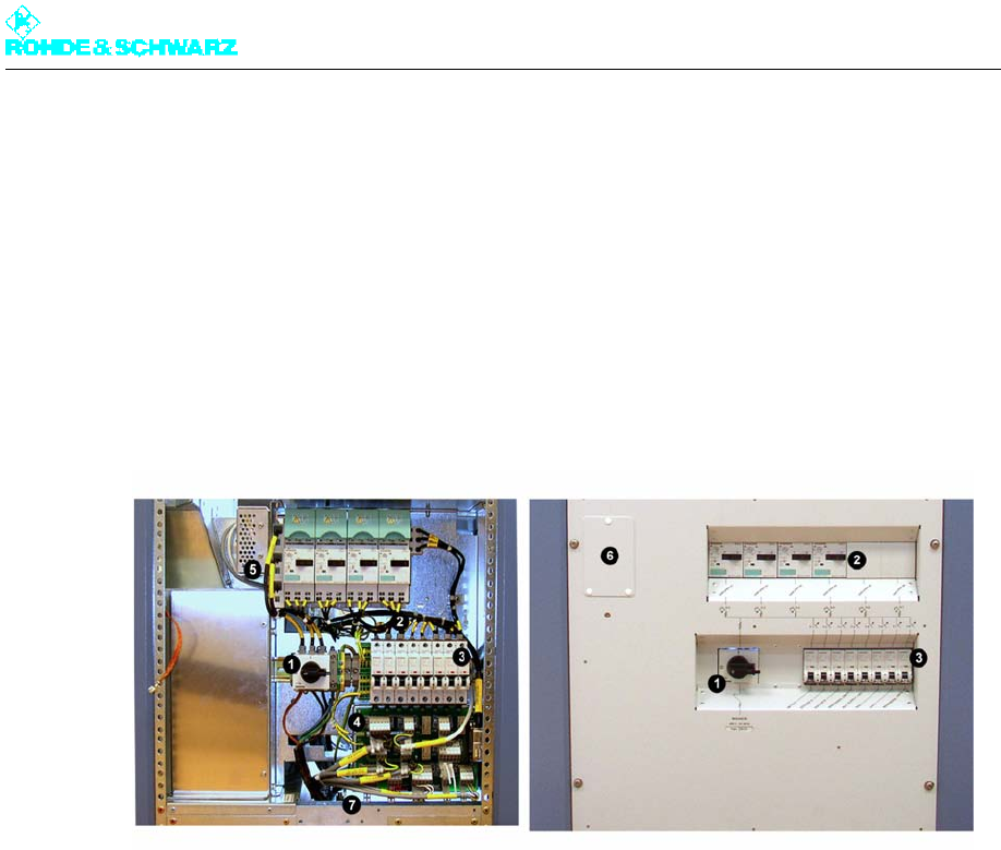
Chapter 2 Design and Characteristics
2098.0188.72 - 2.5 - E-1
– Splitter
– Combiner
– Absorber
The output stage unit in this case only consists of one amplifier.
1.1 Power Distribution
Fig. 3 Power distribution; here R&S NV8304
1) Main switch (power supply terminal)
2) Motor protection switches
3) Automatic line fuses
4) Power distribution board
5) Auxiliary power supply
6) Optional socket
7) Ground bolt
The power distribution is designed for max. 32 A and contains the following components:
Main switch (power supply terminal)
Motor protection switch
Automatic line fuse
Power distribution board
Auxiliary power supply
Optional socket
Grounding bolt
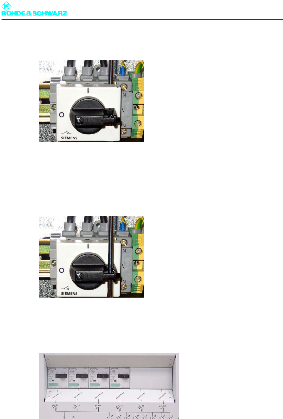
Chapter 2 Design and Characteristics
2098.0188.72 - 2.6 - E-1
1.1.1 Main Switch (Power Supply Terminal)
Fig. 4 Main switch
The main switch fully disconnects the transmitter rack from the AC power supply. It is con-
nected to three-phase alternating current and a neutral conductor.
Note The main switch can be equipped with a padlock to prevent unauthorized persons from
switching it off and on.
Fig. 5 Main switch with fuse
1.1.2 Motor Protection Switches
Fig. 6 Motor protection switches; here R&S NV8304
Motor protection switches act as overload protection for the downstream supply cables and
amplifiers, and are used for disconnecting the amplifiers from the power supply. As shipped
from the factory, the number of motor protection switches matches the number of built-in
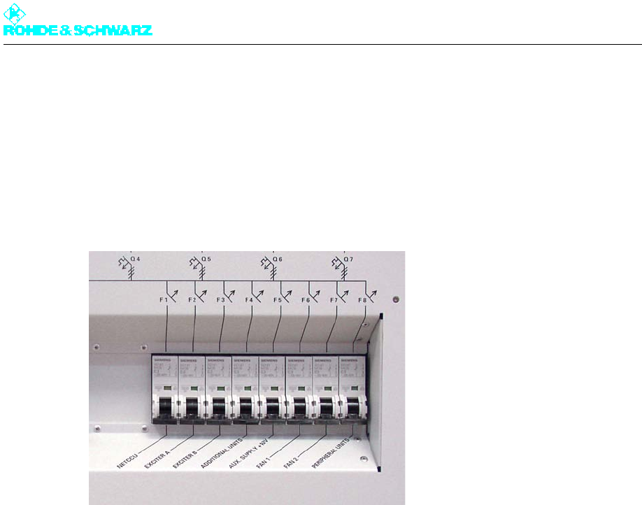
Chapter 2 Design and Characteristics
2098.0188.72 - 2.7 - E-1
amplifiers. The arrangement of amplifiers and motor protection switches is shown on the
front panel.
The thermally activated overcurrent release of the motor protection switches is factory-set.
1.1.3 Automatic Line Fuses
Fig. 7 Automatic line fuses
The automatic line fuses are used to protect the power lines, e.g. in the event of a short-
circuit, and to disconnect the following units from the AC supply:
R&S NetCCU800 (F1)
EXCITER A/B (F2/F3)
Optional add-on equipment (F4)
Auxiliary power supply unit (F5)
Fan (F6/F7)
Control unit (F8)
– External cooling system
– Control unit for dummy antennas
– Optional external fan
The automatic line fuses are labeled with the corresponding device names.
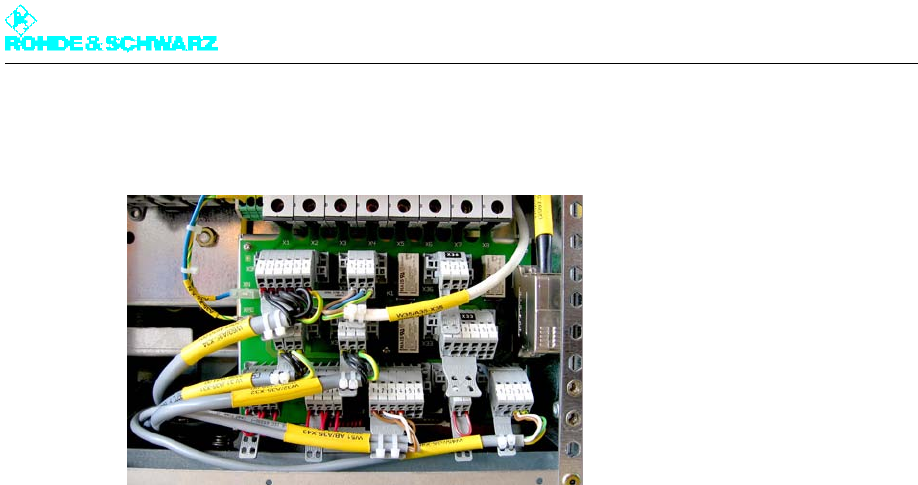
Chapter 2 Design and Characteristics
2098.0188.72 - 2.8 - E-1
1.1.4 Power Distribution Board
Fig. 8 Power distribution board
The power distribution board is directly connected to the automatic line fuses and contains
transmitter-internal cables, which are hard-wired, as well as transmitter-external compo-
nents (customer interfaces), to which you can connect external equipment.
Note The appropriate dummy plugs are part of the transmitter and are located at the assigned
positions.
The following equipment is or can be connected to the power distribution board:
R&S NetCCU800
Exciters A/B
Fans
External fan (switched phase for controlling an external contactor)
External dummy antenna (switched phase for controlling an external contactor)
RF loop
External absorber fault (system absorber)
Overcurrent (external cooling)
Connector for rack controller
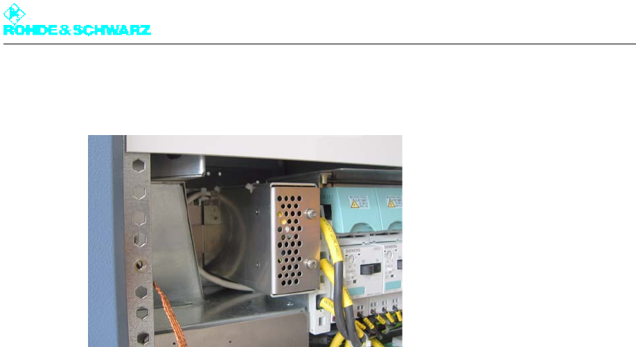
Chapter 2 Design and Characteristics
2098.0188.72 - 2.9 - E-1
1.1.5 Auxiliary Power Supply Unit
Fig. 9 Auxiliary power supply
The primary task of the auxiliary power supply (+12 V) is to provide power to the additional
control components in the rack. The required redundancy of this auxiliary voltage is gener-
ated via the exciters, which also output a +12 V current.
The following modules are powered by the auxiliary power supply:
Rack controller
CAN bus interface of the amplifiers
Switching relay in the power distribution
RF rectifier/directional coupler when the standby transmitter is active
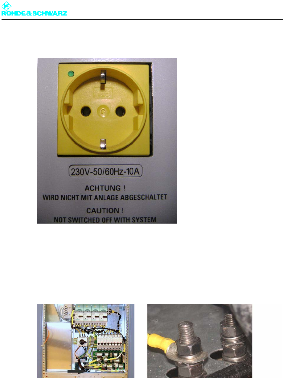
Chapter 2 Design and Characteristics
2098.0188.72 - 2.10 - E-1
1.1.6 Optional Socket
Fig. 10 Optional socket
The optional socket is not connected with the transmitter network and must be supplied by
means of a separate power lead.
1.1.7 Grounding Bolt
Fig. 11 Grounding bolt
The grounding bolt connects the rack with the station's main grounding terminal.
Note The rack must be connected to the main grounding terminal in all cases.
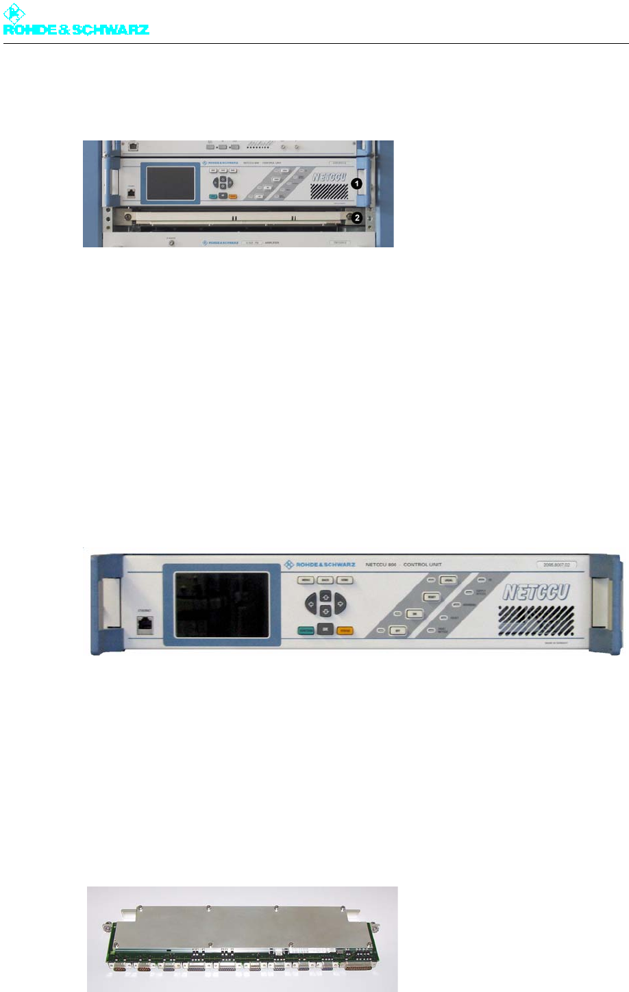
Chapter 2 Design and Characteristics
2098.0188.72 - 2.11 - E-1
1.2 Transmitter Control Unit
Fig. 12 Units used for transmitter control
1) R&S NetCCU800
2) Rack controller
The transmitter control unit contains the following components:
R&S NetCCU800
Rack controller
They monitor and control the transmitter to ensure that it functions properly.
1.2.1 R&S NetCCU800
Fig. 13 R&S NetCCU800
The R&S NetCCU800 transmitter control unit handles internal and external communica-
tions, including all control functions. The R&S NetCCU800 shows the current status of the
transmitter system on a straightforward color display.
Note For detailed information on the R&S NetCCU800, refer to the R&S NetCCU800 manual.
1.2.2 Rack Controller
Fig. 14 Rack controller

Chapter 2 Design and Characteristics
2098.0188.72 - 2.12 - E-1
The rack controller is used to monitor, control, and protect the transmitter rack. It handles
the following functions:
Keeps the transmitter running if the R&S NetCCU800 fails
Controls data exchange between the R&S NetCCU800 and other components via CAN
bus
Monitors the outlet air temperature
Acquires measured data about the intake and outlet air temperatures
Transfers messages
Accepts and outputs rack commands (e.g. transmitter ON -> amplifier ON, cooling sys-
tem ON)
Configures the test points (mode-dependent)
Switches off the rack in the event of malfunction (e.g. fan failure)
The following equipment and modules can be connected to the rack controller:
R&S NetCCU800 via CAN bus
Exciters (1 or 2)
External cooling system (liquid-cooled transmitters)
Amplifier stages (1 or 2)
Power distribution
Temperature sensors
Power test points
Note The rack controller cannot be operated directly. It is operated via the R&S NetCCU800.
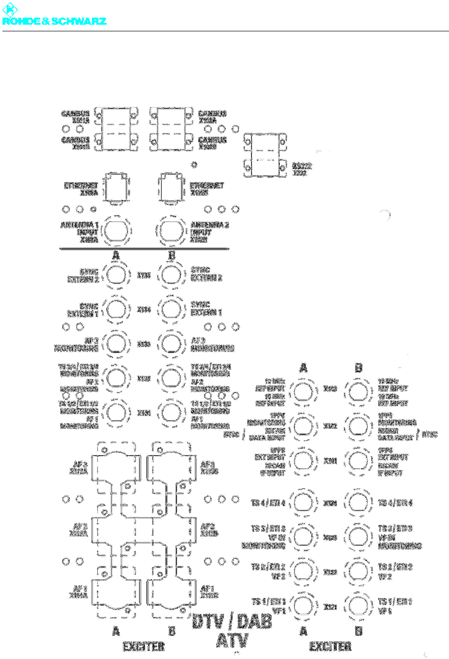
Chapter 2 Design and Characteristics
2098.0188.72 - 2.13 - E-1
1.3 Connection Panel
Fig. 15 Connection panel
The baseband signals as well as the monitoring and remote-control connections are routed
to the transmitter via the connection panel.
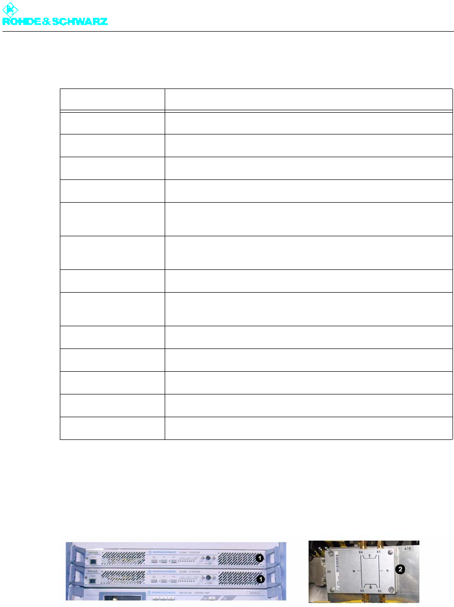
Chapter 2 Design and Characteristics
2098.0188.72 - 2.14 - E-1
The following table describes the connection options:
1.4 Exciter Unit
Fig. 16 Components of exciter unit
1) R&S SX800 exciter
2) Exciter switch (exciter standby only)
The exciter unit contains the following components:
Exciter
Exciter switch (in case of exciter standby)
Connection Description
CANBUS X101A CAN bus data connection for additional racks or output stage A
CANBUS X101B CAN bus data connection for additional racks or output stage B
RS232 X232 Serial data connection for external BITBUS interface
ETHERNET Remote LAN connector or system LAN connector, e.g. for N+1
ANTENNA 1 INPUT Antenna connection for receiver module input 1 in R&S NetCCU800
(DVB-T only)
ANTENNA 2 INPUT Antenna connection for receiver module input 2 in R&S NetCCU800
(DVB-T only)
TS1 / TS2 Transport stream inputs
TS3 / TS4 Additional connections for TS1 and TS2 with hierarchical coding
(DVB-T only)
10 MHz REF INPUT Input for 10 MHz reference for synchronization of output signal
1PPS MONITORING Test output 1PPS (1PPS = 1 pulse per second)
1PPS EXT INPUT Input for 1PPS signal, reference signal in SFN mode
TS1/2 MONITORING Monitor output for selected TS signal of inputs 1 and 2
TS3/4 MONITORING Monitor output for selected TS signal of inputs 3 and 4 (DVB-T only)
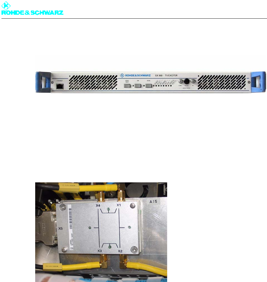
Chapter 2 Design and Characteristics
2098.0188.72 - 2.15 - E-1
1.4.1 Exciter
Fig. 17 Exciter
The SX800 exciter is responsible for all signal processing of the transport stream signal up
to and including an RF output signal conforming to standards.
Note For detailed information about the exciter, refer to the exciter manual.
1.4.2 Exciter Switch
Fig. 18 Exciter switch
Note In transmitters with the exciter standby option (two exciters), the exciter switch is located
behind the two exciters.
The exciter switch switches to the standby exciter in the following cases:
When the main exciter malfunctions
On manual switchover via the R&S NetCCU800
The exciter switch is controlled by the R&S NetCCU800.
1.5 Output Stage Unit
Note This section is not relevant for transmitters having only one amplifier in the rack.
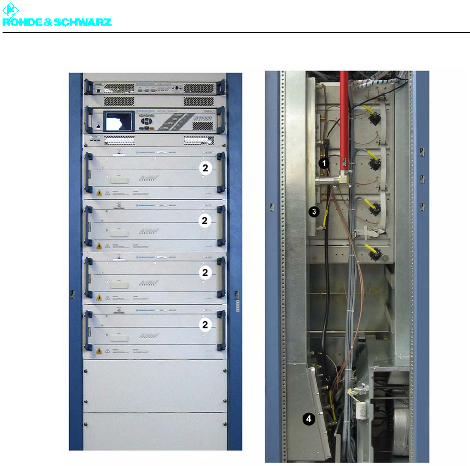
Chapter 2 Design and Characteristics
2098.0188.72 - 2.16 - E-1
Fig. 19 Equipment of output stage unit; here R&S NV8304
1) Splitter
2) Amplifiers
3) Combiner
4) Absorber
The output stage unit contains the following components:
Splitter
Amplifier
Combiner
Absorber
The diagram below shows the entire RF path from X.E. (splitter input) up to X.A. (combiner
output).
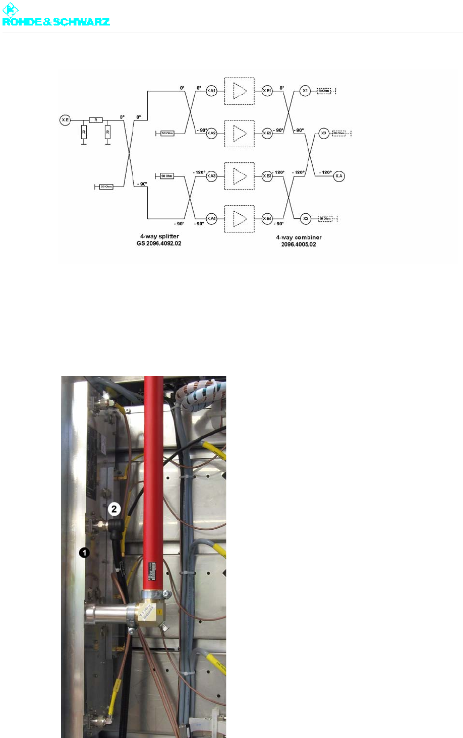
Chapter 2 Design and Characteristics
2098.0188.72 - 2.17 - E-1
Fig. 20 Block diagram of output stage unit: Example of the R&S NV8304
1.5.1 Splitter
Note This section is not relevant for transmitters having only one amplifier in the rack.
Fig. 21 Combiner (1) with splitter (2); here R&S NV8304
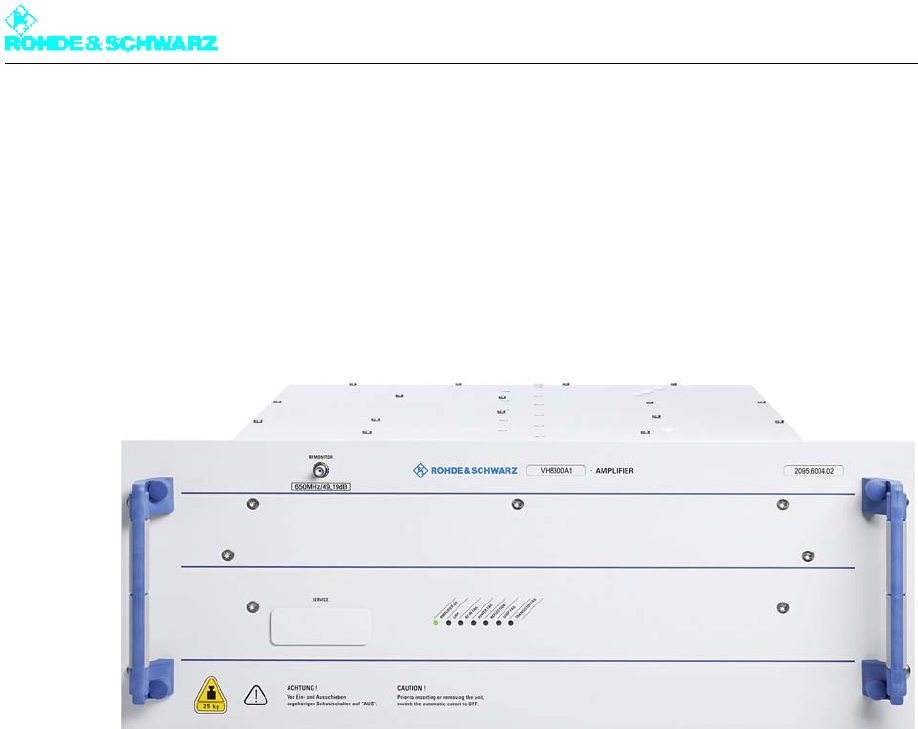
Chapter 2 Design and Characteristics
2098.0188.72 - 2.18 - E-1
The splitter distributes the output signal of the exciter to the individual amplifiers. In addition,
an integrated attenuator that is dependent on the number of outputs ensures that the RF
signal is output at the right power level.
The splitter is a broadband unit that operates in the frequency range 470 MHz to 862 MHz.
1.5.2 Amplifier
Fig. 22 R&S VH8300A1 amplifier
The R&S VH8300A1 air-cooled amplifier operates in the broadband range from 470 MHz
to 862 MHz (UHF bands IV/V) and is suitable for both analog and digital signals without
needing to be adjusted. The output power of an amplifier is, depending on the requirements
with regard to the MER, between 450 W und 500 W.
The amplifiers amplify the exciter signals distributed by the splitter and forward them to the
combiner. The amplifiers in a transmitter rack are controlled via the rack controller. Mea-
sured values and status information are recorded by the rack controller via CAN bus and
forwarded to the R&S NetCCU800 transmitter control unit. The number of amplifiers in the
transmitter depends on the transmit power.
Note For detailed information about the amplifier, refer to the amplifier manual.
Transmitters with one amplifier in rack
In transmitters with only one amplifier in the rack, the splitter and combiner are omitted. The
signals of the exciter are fed directly to the amplifier and, following amplification, routed fur-
ther downstream in the signal path to the harmonics filter.
1.5.3 Combiner
Note This section is not relevant for transmitters having only one amplifier in the rack.
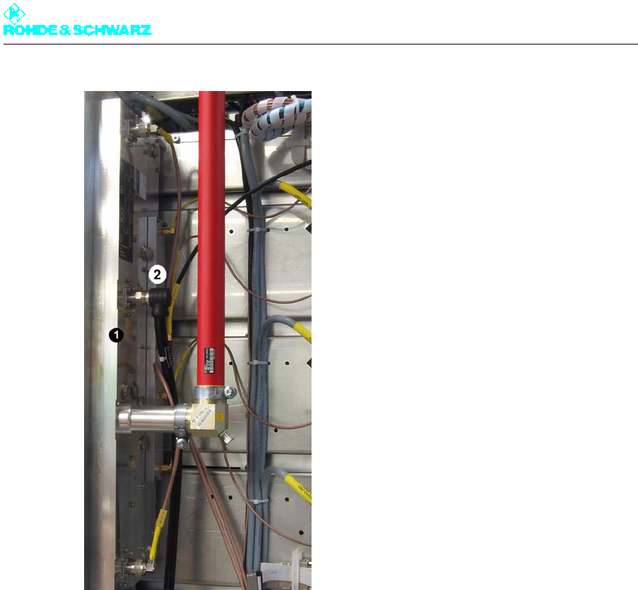
Chapter 2 Design and Characteristics
2098.0188.72 - 2.19 - E-1
Fig. 23 Combiner (1) with splitter (2); here R&S NV8304
The RF power output from the amplifiers is merged with the correct phase via the combiner.
The combiner consists of a cascade of 90° hybrids housed in a single unit.
1.5.4 Absorber
Note This section is not relevant for transmitters having only one amplifier in the rack.
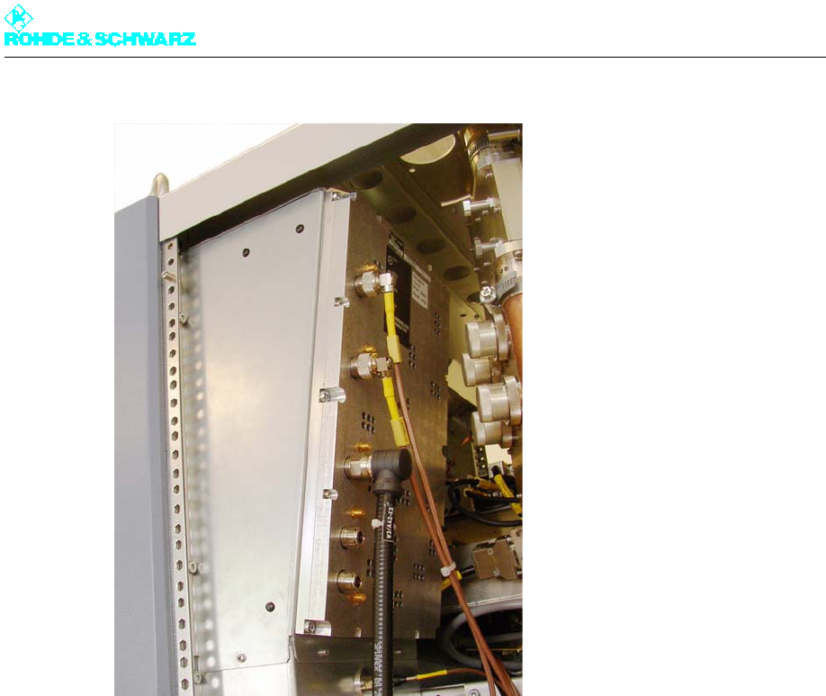
Chapter 2 Design and Characteristics
2098.0188.72 - 2.20 - E-1
Fig. 24 Absorber
The absorber resistors (dummy loads) for the combiner are located on the absorber block.
When the combiner is being operated in unbalanced mode (e.g. with one or more amplifiers
disabled or removed) the non-combinable component of the RF power is expelled as addi-
tional heat energy via the transmitter exhaust duct.
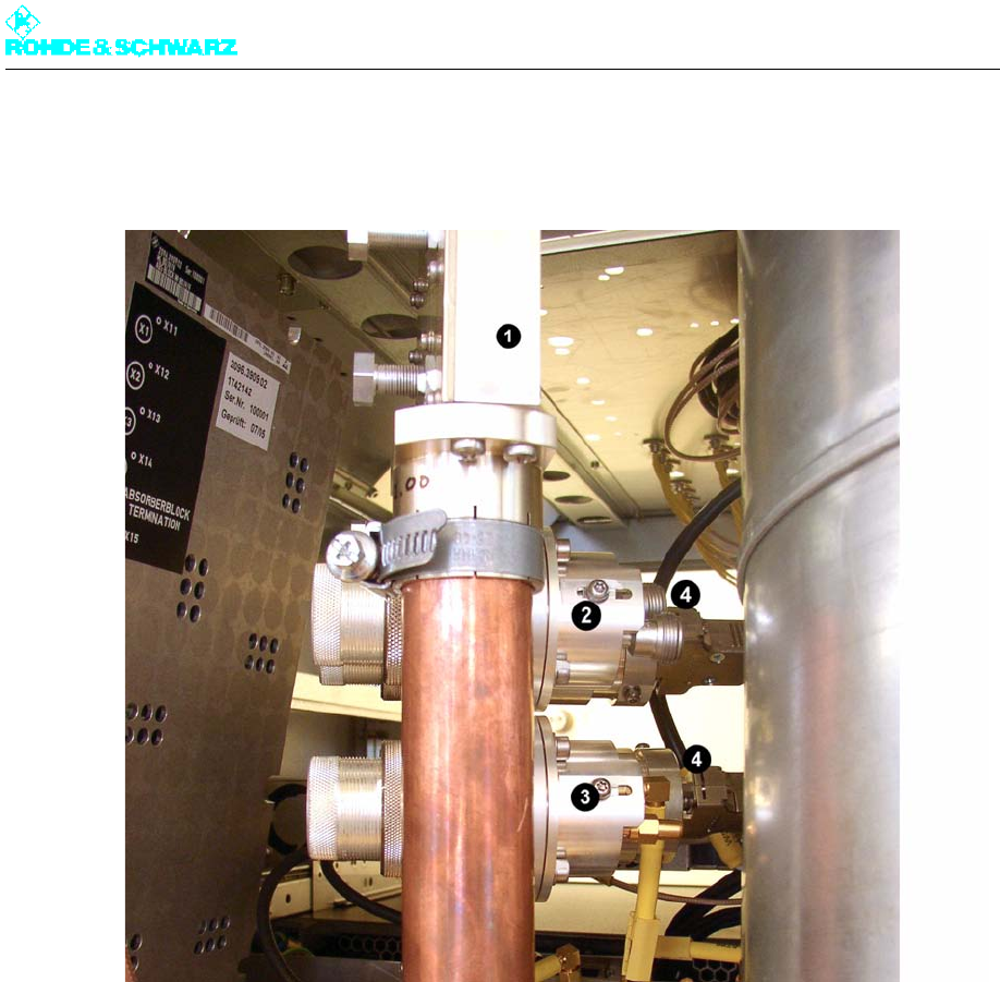
Chapter 2 Design and Characteristics
2098.0188.72 - 2.21 - E-1
1.6 Directional Coupler Lightning Protection System
Fig. 25 Equipment in test lightning protection system
1) Lightning arrester
2) Directional coupler with N connector
3) Directional coupler with SMA connector
4) Directional coupler with rectifier unit
The directional coupler/lightning protection system (combined lightning arrester with test
points) is located at the output of the harmonics filter and contains the following compo-
nents:
Lightning arrester
Directional coupler with N connector
Directional coupler with SMA connector (with automatic and adaptive precorrection
(ADE) option only)
Directional coupler and rectifier unit
1.6.1 Lightning Arrester
The lightning protection protects the transmitter from damage caused by a lightning strike.
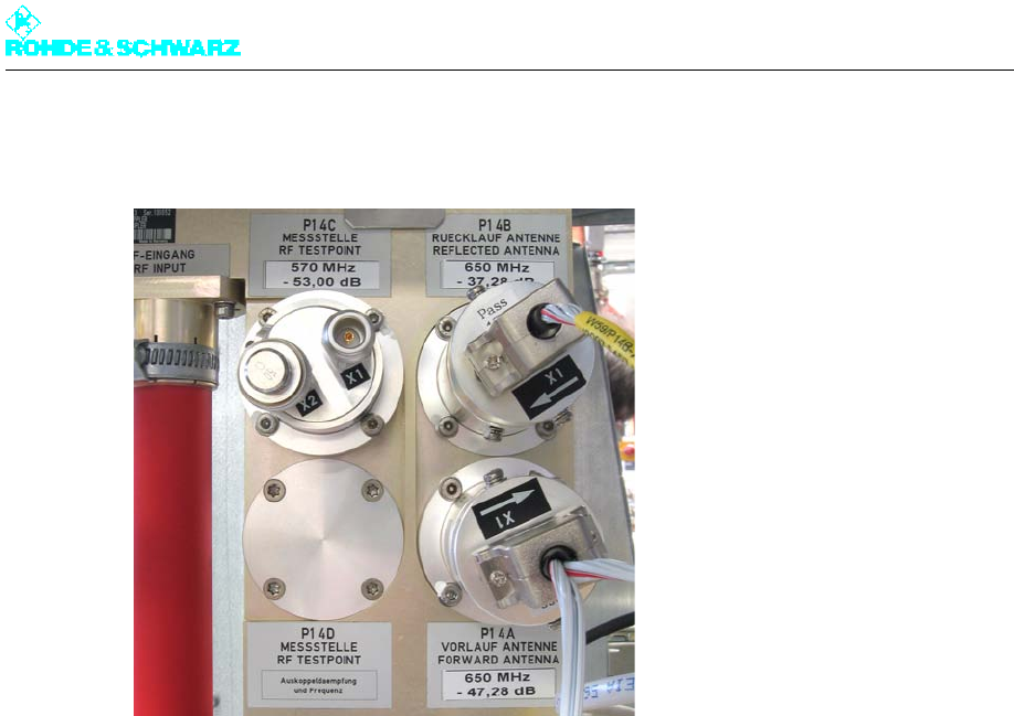
Chapter 2 Design and Characteristics
2098.0188.72 - 2.22 - E-1
1.6.2 Directional Couplers
Fig. 26 Directional couplers
The forward and reflected power is detected at the transmitter output by means of the fre-
quency-compensated directional couplers P14A (forward) and P14B (reflected). The fre-
quency-compensated directional couplers output a power-proportional DC voltage to the
R&S NetCCU800 transmitter control unit via the integrated rectifier circuit. The DC voltages
for forward and reflected power are displayed in the R&S NetCCU800 and also used as an
S measurement for VSWR monitoring (reflection on the antenna).
Directional coupler P14C is a free test point that can be used either as a forward or reflected
power test point.
The P14D rectifier is used in the digital TV transmitter only in combination with the ADE op-
tion.
Note The transmitter is switched off due to reflection if the reflected value exceeds 2% of the for-
ward value after being checked three times.
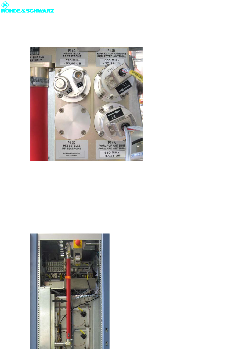
Chapter 2 Design and Characteristics
2098.0188.72 - 2.23 - E-1
1.6.3 Directional Coupler Interface
Fig. 27 Directional coupler interface
The free directional coupler interface can be used for connecting external power measuring
instruments.
1.7 Harmonics Filter
Fig. 28 Harmonics filter; here R&S NV8304
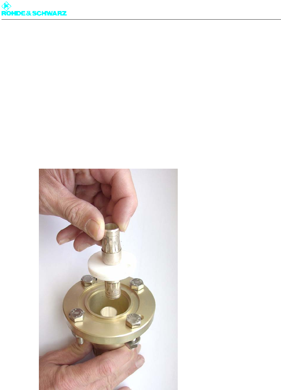
Chapter 2 Design and Characteristics
2098.0188.72 - 2.24 - E-1
The FH 825 harmonics filter is used to suppress harmonics. It is a 23rd order Chebyshev
filter which uses coaxial technology so that it is suitable for the rigid line system 13-30. On
the signal path, the harmonics filter is located directly downstream of the combiner.
Note The harmonics filter is varnished to reduce the surface temperature.
Transmitters with one amplifier in rack
In transmitters having only one amplifier in the rack, the harmonics filter is connected direct-
ly with the RF output of the amplifier via a coaxial cable.
1.8 RF Connector
Fig. 29 RF connector
The RF connector (1 5/8“ EIA flange) is located on the transmitter roof (or under it if pre-
ferred).
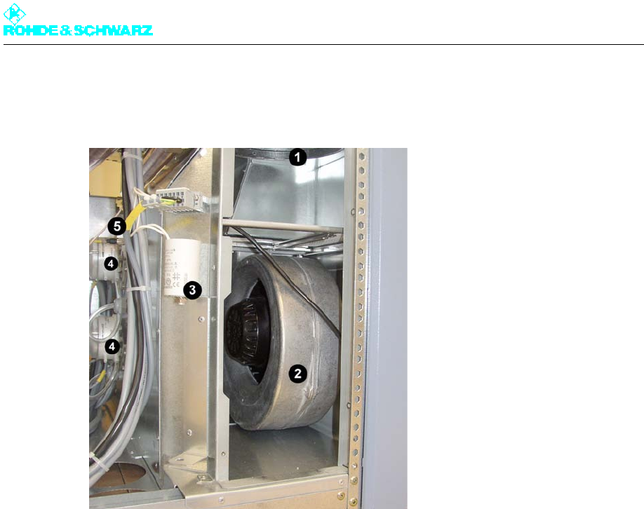
Chapter 2 Design and Characteristics
2098.0188.72 - 2.25 - E-1
1.9 Cooling System
Fig. 30 Cooling system
1) Air intake duct
2) Fan
3) Starting capacitor
4) Differential pressure gage
5) Temperature sensor
The cooling system consists of two built-in fans on active standby and contains the following
components:
Air intake/exhaust ducts
Fans (2)
Starting capacitors (2)
Differential pressure gages (2)
Temperature sensors (2)
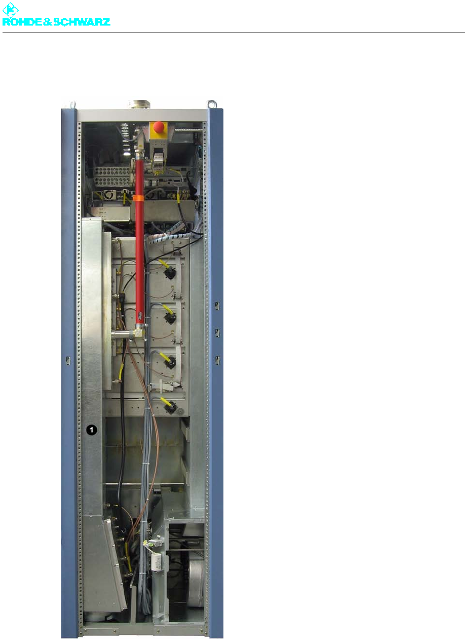
Chapter 2 Design and Characteristics
2098.0188.72 - 2.26 - E-1
1.9.1 Intake/Exhaust Air Ducts
Fig. 31 Intake air duct (1) and exhaust air duct (2); here R&S NV8304 with option intake air from below
The air from the intake duct is drawn in by the fans and forwarded to the distribution shaft.
The distribution shaft provides enough air to each amplifier to cool it. The heated air is rout-
ed to an air collecting shaft on the opposite side of the amplifier and expelled via the ex-
haust duct.
Note The intake/exhaust outputs are located either on the top or bottom of the rack, depending
on your order specifications.
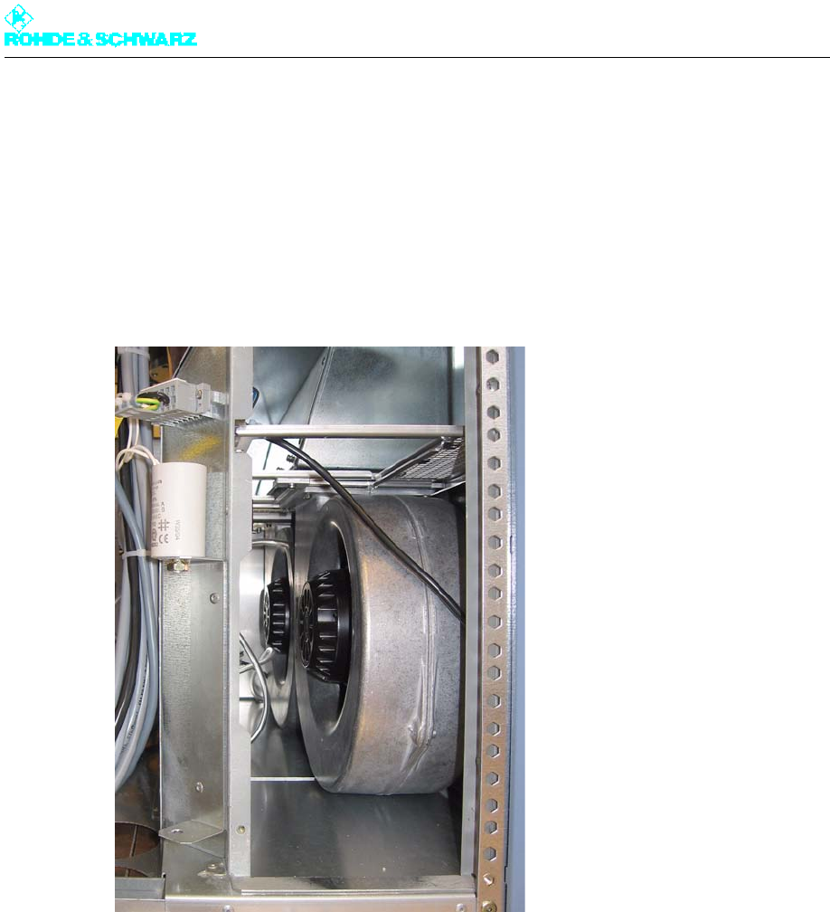
Chapter 2 Design and Characteristics
2098.0188.72 - 2.27 - E-1
If the intake is at the bottom, there is no intake duct. The connecting flange is then located
directly beneath the fan box.
If the exhaust air is directed downward, the absorber unit is situated at the bottom and feeds
into the exhaust connection.
1.9.2 Fans
Fig. 32 Fans
A standard transmitter rack contains two fans, which adequately cool the transmitter with
air. If one of the fans is defective, a warning is sent to the controller but the transmitter con-
tinues to operate. If both fans fail, the rack controller switches off the affected rack. The
transmitter indicates a cooling malfunction.
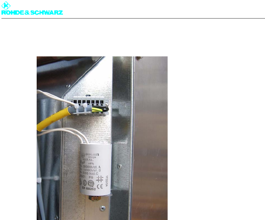
Chapter 2 Design and Characteristics
2098.0188.72 - 2.28 - E-1
1.9.3 Starting Capacitors
Fig. 33 Starting capacitor
Each motor is equipped with an external starting capacitor.

Chapter 2 Design and Characteristics
2098.0188.72 - 2.29 - E-1
1.9.4 Differential Pressure Gages
Fig. 34 Differential pressure gages
The differential pressure gages (diaphragm switches) measure the differential pressure of
each fan between the fan flange (output) and the environment. Thus, fan malfunctions can
be selectively sent to the transmitter control unit.
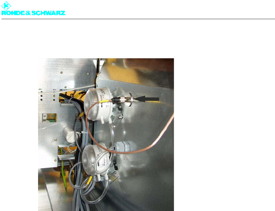
Chapter 2 Design and Characteristics
2098.0188.72 - 2.30 - E-1
1.9.5 Temperature Sensors
Fig. 35 Temperature sensors
The temperature sensors measure the absolute intake and exhaust air temperatures in °C
for display on the R&S NetCCU800 and monitoring in the rack controller.
Note If the exhaust temperature exceeds 65 °C, the rack controller switches off the rack due to
the risk of overheating.

Chapter 2 Design and Characteristics
2098.0188.72 - 2.31 - E-1
2 Specifications
2.1 Transmitter System – General
Frequency range ........................................ 470 MHz to 862 MHz
Standard .................................................... ATSC
Transmission bandwidth ............................ 6 MHz
Voltage supply ........................................... 230 V / 400 V ± 15 %
47 Hz to 63 Hz
Three-phase current (3W+N+PE)
cos > 0.9
Power output stage .................................... Fully transistorized (LDMOS)
Maximum installation altitude ..................... 2000 m above sea level (higher than 2000 m
on request)
Operating temperature range ..................... +1 °C to +45 °C
Max. permissible humidity .......................... 95 %, non-condensing
Dimensions (W x H x D) ............................. 600 mm x 2000 mm x 800 mm
RF connector ............................................. 15/8 EIA
VSWR ........................................................ s 1.3
Operating mode
Coding and modulation .............................. in accordance with ATSC Doc. A/53
Synchronization
Reference frequency ................................. 10 MHz, 0.1 Vpp to 5 Vpp or TTL, BNC
Reference pulse ........................................ 1 Hz, TTL, BNC
Inputs
ATSC ......................................................... ASI/SMPTE 1 and ASI/SMPTE 2, BNC
Operation
Local .......................................................... Color display and keys
for front-panel operation via graphical user in-
terface (GUI)
RJ45 .......................................................... Operated from the PC using a standard web
browser
Remote ...................................................... IEC 864-2 via Ethernet (standard) and optional
network management interface (WEB server

Chapter 2 Design and Characteristics
2098.0188.72 - 2.32 - E-1
and/or SNMP agent);
optional parallel I/O Interface (floating contacts
and commands);
optional BitBus interface to IEC 864-2
Spurious emissions
Harmonics ................................................. 70 dBc
Spurious ..................................................... 60 dBc
Noise power ratio ....................................... 130 dBc
Note To adhere to national standards on the antenna interface, the transmitter may only be op-
erated with an external output bandpass.
Recommended bandpass for suppressing spurious emissions
(example 6 MHz channel bandwidth):
f0 ± 3.5 MHz ............................................... 3 dB
f0 ± 4.0 MHz ............................................... 8 dB
f0 ± 6.0 MHz ............................................... 30 dB
f0 ± 9.0 MHz ............................................... 65 dB
Shoulder distance at ± 3.25 MHz .............. > 37 dB
Electrical safety ......................................... to EN60215 / EN60950
2.2 Transmitter System – Specific
2.2.1 R&S NV8301
Number of amplifiers ................................. 1
Pout with MER 34 dB .............................. 430 W
Pout with MER 33 dB .............................. 500 W
Air flow rate ................................................ At least 8 m3/min
Power consumption (worst case) .............. 2.8 kW with Poutmax
Heat dissipation ducted (worst case) ......... 1.6 kW
Heat dissipation to surrounding air ............ approx. 275 W
Additional fuses
Backup fuse (type NH gG) ......................... 3 x 20 A

Chapter 2 Design and Characteristics
2098.0188.72 - 2.33 - E-1
Connection cross-section .......................... 2.5 mm2 / AWG 12
Backup fuse ............................................... 16 A to 20 A (setting value: 16 A)
(Automatic line fuse, e.g. Siemens 3VL1702-1DD33)
Connection cross-section .......................... 2.5 mm2 / AWG 12
Total weight (approx.) ................................ 235 kg
2.2.2 R&S NV8302
Number of amplifiers ................................. 2
Pout with MER 34 dB .............................. 860 W
Pout with MER 33 dB .............................. 1000 W
Air flow rate ................................................ At least 12 m3/min
Power consumption (worst case) .............. 4.9 kW with Poutmax
Heat dissipation ducted (worst case) ......... 3.1 kW
Heat dissipation to surrounding air ............ approx. 350 W
Additional fuses
Backup fuse (type NH gG) ......................... 3 x 20 A
Connection cross-section .......................... 2.5 mm2 / AWG 12
Backup fuse ............................................... 16 A to 20 A (setting value: 16 A)
(Automatic line fuse, e.g. Siemens 3VL1702-1DD33)
Connection cross-section .......................... 2.5 mm2 / AWG 12
Total weight (approx.) ................................ 270 kg
2.2.3 R&S NV8303
Number of amplifiers ................................. 3
Pout with MER 34 dB .............................. 1290 W
Pout with MER 33 dB .............................. 1500 W
Air flow rate ................................................ At least 15 m3/min
Power consumption (worst case) .............. 7.0 kW with Poutmax
Heat dissipation ducted (worst case) ......... 4.6 kW
Heat dissipation to surrounding air ............ approx. 425 W

Chapter 2 Design and Characteristics
2098.0188.72 - 2.34 - E-1
Additional fuses
Backup fuse (type NH gG) ......................... 3 x 20 A
Connection cross-section .......................... 2.5 mm2 / AWG 10
Backup fuse ............................................... 16 A to 20 A (setting value: 20 A)
(Automatic line fuse, e.g. Siemens 3VL1702-1DD33)
Connection cross-section .......................... 2.5 mm2 / AWG 10
Total weight (approx.) ................................ 300 kg
2.2.4 R&S NV8304
Number of amplifiers ................................. 4
Pout with MER 34 dB .............................. 1720 W
Pout with MER 33 dB .............................. 1800 W
Air flow rate ................................................ At least 17 m3/min
Power consumption (worst case) .............. 10.0 kW with Poutmax
Heat dissipation ducted (worst case) ......... 7.2 kW
Heat dissipation to surrounding air ............ approx. 500 W
Additional fuses
Backup fuse (type NH gG) ......................... 3 x 25 A
Connection cross-section .......................... 4.0 mm2 / AWG 10
Backup fuse ............................................... 25 A to 32 A (setting value: 25 A)
(Automatic line fuse, e.g. Siemens 3VL1703-1DD33)
Connection cross-section .......................... 4.0 mm2 / AWG 10
Total weight (approx.) ................................ 325 kg

Broadcasting Division
2095.7346.32 - 3.0 - E-1
CHAPTER 3
INSTALLATION
Printed in Germany

Chapter 3 Installation
2098.0188.72 - 3.01 - E-1
CONTENTS
1 Equipment Supplied ........................................................................ 1
1.1 Integrated Transmitter Components ............................................................1
1.2 Transmitter Components Supplied Separately ...........................................2
2 Overview ........................................................................................... 3
3 Setting Up Transmitter .................................................................... 4
3.1 Preparations ....................................................................................................4
3.1.1 Checking Structure, Flatness and General Suitability of Installation
Surface .........................................................................................................4
3.1.2 Preparing Floor Openings (only if Feed and Return pass through Floor) ....4
3.1.3 Arranging Connections on Transmitter Roof ................................................6
3.2 Erecting Transmitter Rack .............................................................................7
3.3 Aligning Transmitter Rack .............................................................................7
3.4 Fastening the Transmitter Rack to the Floor ...............................................7
3.5 Removing Front Panels/Rear Panel ..............................................................7
3.6 Unpacking Components ................................................................................8
4 Ventilation System ........................................................................... 9
4.1 Connecting Air Intake/Exhaust Ducts ..........................................................9
4.2 Connecting External Backup Fan ...............................................................12
4.3 Checking Ventilation Covers .......................................................................12
4.4 Checking Differential Pressure Gages .......................................................13
5 AC Power Supply ........................................................................... 14
5.1 Connecting Transmitter Ground .................................................................15
5.2 Connecting AC Power Cable .......................................................................15
5.3 Connecting External Equipment .................................................................17
6 Amplifiers ....................................................................................... 19
6.1 Installing Amplifiers .....................................................................................19
7 Connecting Antenna/Dummy Antenna to RF Connector ........... 20
7.1 Connecting Antenna ....................................................................................20

Chapter 3 Installation
2098.0188.72 - 3.02 - E-1
7.2 Connecting Dummy Antenna ......................................................................21
8 Connection Panel .......................................................................... 23
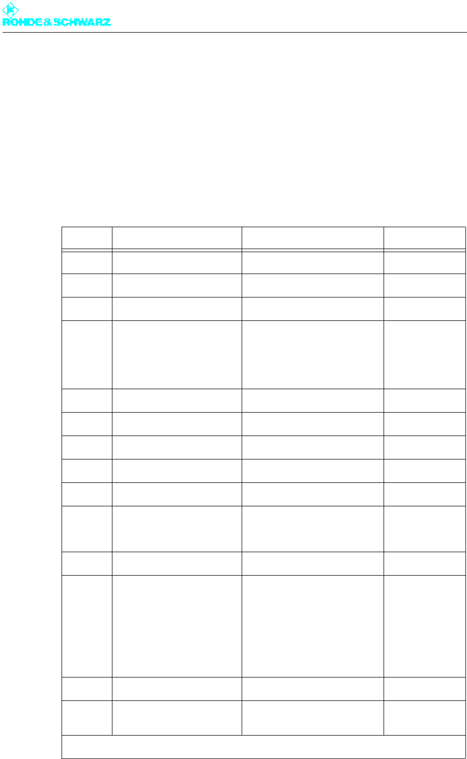
Chapter 3 Installation
2098.0188.72 - 3.1 - E-1
1 Equipment Supplied
1.1 Integrated Transmitter Components
In the case of transmitters in the R&S NV8300E/V family, the following units and modules
are already installed in the rack (depending on the equipment supplied):
Note Use the tables below to check that all the relevant components have been supplied.
Quantity Part name Type ID
1 Cabinet rack R&S KG830M1 2096.2002.02
1 Mid-range power distribution 2096.3344.XX
1 R&S NetCCU800 R&S NetCCU800 2095.8007.02
1 - 2 TV exciter SX800
Transmitter type:
NV830xE
NV830xV
R&S SV800
Quantity of R&S SV800
1
2
2095.1502.XX
1 Auxiliary power supply unit 1081.0254.00
1 Rack Controller 2096.4505.02
2 Barometric capsule 2077.3936.00
2 Temperature sensor 2010.0006.00
2 Fan set 2096.2131.02
1 Exciter switch
(only with exciter standby
option)
2095.3257.02
1 Harmonics filter R&S FH825 2096.6508.02
1 Coupler/splitter unit
Transmitter type:
R&S NV8301
R&S NV8302
R&S NV8303
R&S NV8304
Combiner unit
none
2-way combiner R&S BV832H1
3-way combiner R&S BV833H1
4-way combiner R&S BV834H1
2096.4305.02
2096.4157.02
2096.4005.02
1 Absorber unit 2096.3909.02
1 Directional coupler with light-
ning protection
R&S GD800 2096.7204.44
Enclosed loose
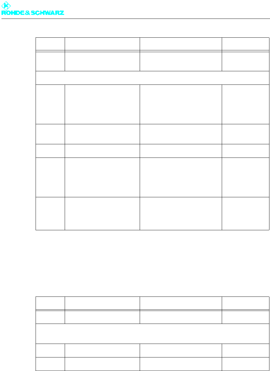
Chapter 3 Installation
2098.0188.72 - 3.2 - E-1
1.2 Transmitter Components Supplied Separately
The transmitter contains the following components that must be installed in the rack after
delivery.
1 Strain relief for AC supply
feed
Options
1 Hazard button kit
VAR: 11 = 1 button on front
VAR: 12 = Button on front
and rear
VAR: 13 = Button on rear
R&S ZR800N1 2099.4506.VAR
1 Parallel remote control inter-
face
R&S ZR800F1 3562.4210.02
1 External socket kit R&S ZR800Z1 2099.3000.02
1 Internal socket kit
VAR: 14 = 4-socket low-tem-
perature connector strip
VAR: 16 = 6-socket low-tem-
perature connector strip
R&S ZR800Z2 2099.3100.VAR
1 TS distributor kit
VAR: 10 = 1 ASI distributor
VAR: 20 = 2 ASI distributors
(TS3/4)
R&S ZR800Z4 2099.3300.VAR
Quantity Part name Type ID
1 - 4 UHF amplifier R&S VH8300A1 2095.6004.02
NX82xx accessories
consisting of:
1 Coupler 13/30-7/16 2096.7004.00
2 Cover for air outlet 2096.2925.00
Quantity Part name Type ID

Chapter 3 Installation
2098.0188.72 - 3.3 - E-1
2 Overview
The transmitter is installed by following the sequence given below:
Setting up the transmitter
– Checking the structure, flatness and general suitability of the installation surface
– Preparing openings required in the floor (only with inlets and outlets from below)
– Arranging the connections on the transmitter roof
– Erecting the transmitter rack
– Aligning the transmitter rack
– Bolting the transmitter rack to the floor
– Removing the front panels/rear panel
– Unpacking the components
Ventilation system
– Connecting the intake/exhaust air ducts
– Connecting the external backup fan (optional)
– Checking the ventilation covers
AC power supply
– Connecting the transmitter ground
– Connecting the power cable
– Connecting the external units
Installing the amplifiers
RF output
– Connecting the antenna
– Connecting the dummy antenna
Program feed/remote (connection panel)
A detailed description of the installation procedure is provided in the following chapters.

Chapter 3 Installation
2098.0188.72 - 3.4 - E-1
3 Setting Up Transmitter
Make sure that the transmitter is standing in a stable position and that ventilation is suffi-
cient.
Note During installation, the transmitter must be easily accessible from the front and rear. A
clearance space of at least 1.2 m is necessary in order to install all components.
3.1 Preparations
Before setting up and installing the transmitter, you must make the following preparations:
Check general suitability of location
Prepare any openings required in the floor
Set screw holes in floor for fixing the rack (optional)
3.1.1 Checking Structure, Flatness and General Suitability of
Installation Surface
Before installing the transmitter you must check whether the floor of the building in which
the transmitter is to be operated has an adequate weight to floor-area ratio.
The total weight of a transmitter rack can be as much as 385 kg when fully equipped with
plug-in units. This results in a weight to floor-area ratio of at least 800 kg/m2.
Note The exact weight of your transmitter is given in the specifications.
The installation surface should be flat (i.e. horizontal along all axes) and measure 600 mm
x 800 mm to accommodate the transmitter rack.
Note During installation, the transmitter must be easily accessible from the front and rear. A
clearance space of at least 1.2 m is necessary in order to install all components.
Check the structure, flatness and general suitability of the chosen installation location.
3.1.2 Preparing Floor Openings (only if Feed and Return pass
through Floor)
If the intention is to connect cables (RF cable, control lines etc.) or intake air/exhaust air
feeds from below, the appropriate floor openings need to be made in the operational build-
ing.
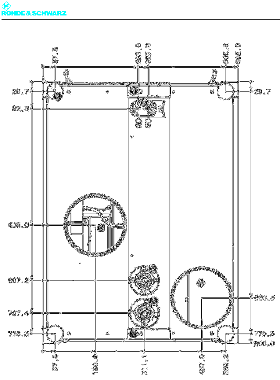
Chapter 3 Installation
2098.0188.72 - 3.5 - E-1
Fig. 1 Transmitter floor dimensioning
1) Adjustable foot (Ø 50)
2) AC supply input
3) Bottom intake (flange Ø178)
4) Bottom exhaust (flange Ø178)
5) Bottom RF output (ATV, 1 5/8 EIA)
6) Bottom RF output (DTV, 1 5/8 EIA)
7) Attachment hole (floor)
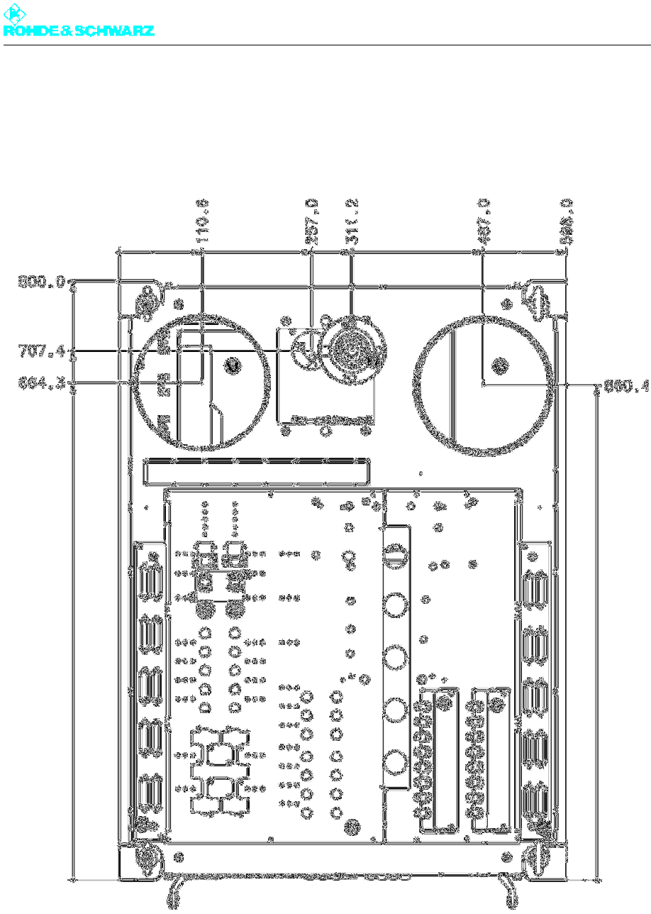
Chapter 3 Installation
2098.0188.72 - 3.6 - E-1
3.1.3 Arranging Connections on Transmitter Roof
When making preparations for installing the station, please observe the following drawing
of the transmitter roof.
Fig. 2 Transmitter roof dimensioning
1) Intake (flange Ø178)
2) Exhaust (flange Ø178)
3) Remote control interface
4) Remote control interface (optional)
5) Transmitter connection panel
6) TS distributor
7) RF output (1 5/8 EIA)
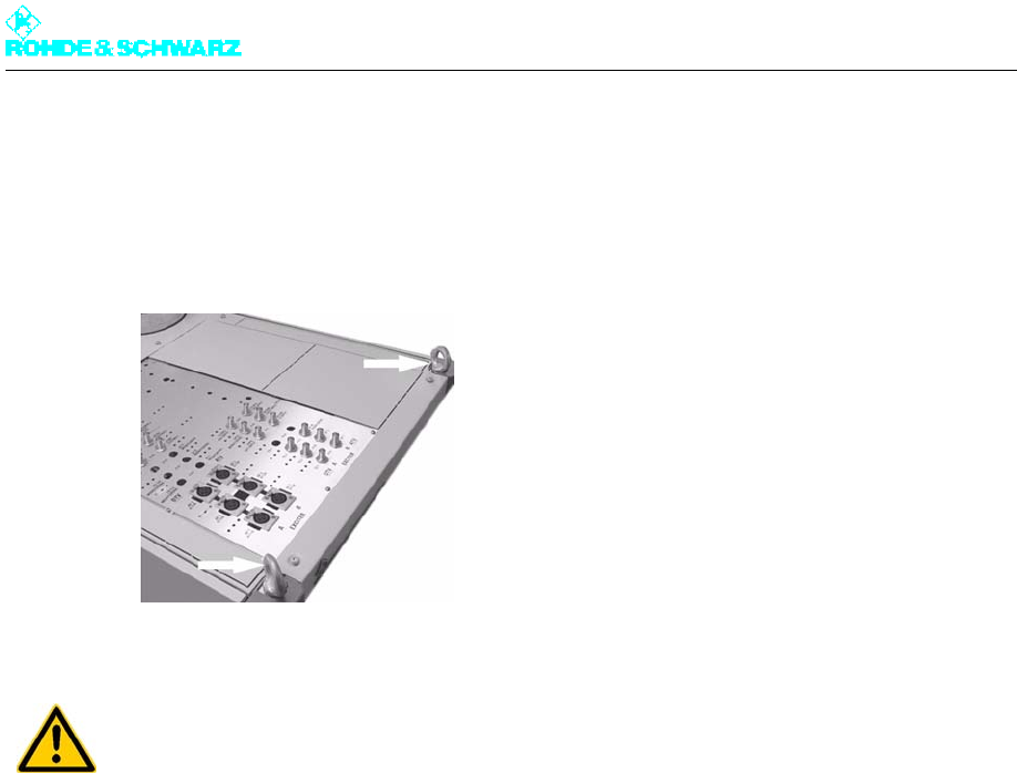
Chapter 3 Installation
2098.0188.72 - 3.7 - E-1
3.2 Erecting Transmitter Rack
The transmitter rack can be set up using lift equipment (crane). Lifting eyes are attached to
the rack roof for this purpose.
Fig. 3 Lifting eyes
3.3 Aligning Transmitter Rack
The rack must be aligned vertically and horizontally in order to prevent distortion caused by
shearing forces.
Use a spirit level to align the rack.
Using the height-adjustable rack feet, align the rack such that it is vertical and horizontal
along all axes.
3.4 Fastening the Transmitter Rack to the Floor
If required the transmitter rack can be screwed to the floor or to a floor-frame. Two 12-mm
boreholes are provided in the lower crossbeam of the transmitter rack for this purpose.
3.5 Removing Front Panels/Rear Panel
Before you start installing the individual units, make sure that you have easy access to all
units, connectors and interfaces needed.
WARNING!
Do not stand under suspended racks, otherwise you could be crushed.
Take the relevant safety precautions when climbing ladders, otherwise you could fall.
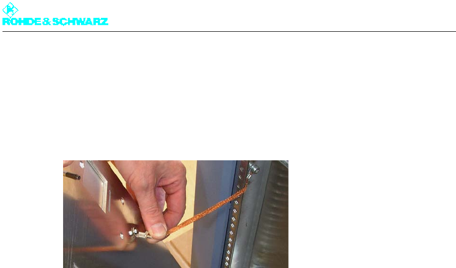
Chapter 3 Installation
2098.0188.72 - 3.8 - E-1
Using a Torx screwdriver No. 20, remove all front panels and the rear panel from the
rack.
This allows you to reach all the necessary units, connectors and interfaces.
Note Pay attention to the ground connections when removing and fitting the front panels and the
rear panel.
Fig. 4 Ground connection on a front panel
3.6 Unpacking Components
Each transmitter component is packaged separately.
Remove the packaging and arrange all equipment so that it is ready for installation.

Chapter 3 Installation
2098.0188.72 - 3.9 - E-1
4 Ventilation System
Note The ventilation system is already installed and wired inside the transmitter.
4.1 Connecting Air Intake/Exhaust Ducts
The intake and exhaust air outlets are located either on the top or bottom of the transmitter
rack, depending on your order specifications. The "Intake air from room" option is also avail-
able. In this case, the intake air is routed to the intake box via an integrated air filter on the
rear panel.
The external pressure drop must not exceed 100 Pa for the required air volume (e.g. for
R&S NV8304, 4 amplifiers: 17 m2/min).
As a result, a pipe system of max. 12 m in length (D = 250 mm), two 90° bends and an air
filter with a drop in discharge pressure of 40 Pa can be installed.
Note Always use pipes with a diameter of 250 mm.
Note Be sure to connect the intake and exhaust lines properly, otherwise the system may be-
come overheated.
The following drawings show the dimensioning on the top and base of the transmitter re-
quired for properly connecting the transmitter to the station.
ATTENTION!
The temperature of the cooling air must not drop below the dew point, otherwise conden-
sation may occur in the air shafts.
If intake air is fed in directly from outside the building, an air filter must be used.
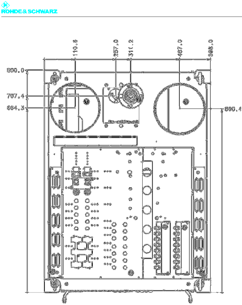
Chapter 3 Installation
2098.0188.72 - 3.10 - E-1
Fig. 5 Transmitter roof dimensioning
1) Intake (flange Ø178)
2) Exhaust (flange Ø178)
3) Remote control interface
4) Remote control interface (optional)
5) Transmitter connection panel
6) TS distributor
7) RF output (1 5/8 EIA)

Chapter 3 Installation
2098.0188.72 - 3.11 - E-1
Fig. 6 Transmitter floor dimensioning
1) Adjustable foot (Ø 50)
2) AC supply input
3) Bottom intake (flange Ø178)
4) Bottom exhaust (flange Ø178)
5) Bottom RF output (ATV, 1 5/8 EIA)
6) Bottom RF output (DTV, 1 5/8 EIA)
7) Attachment hole (floor)
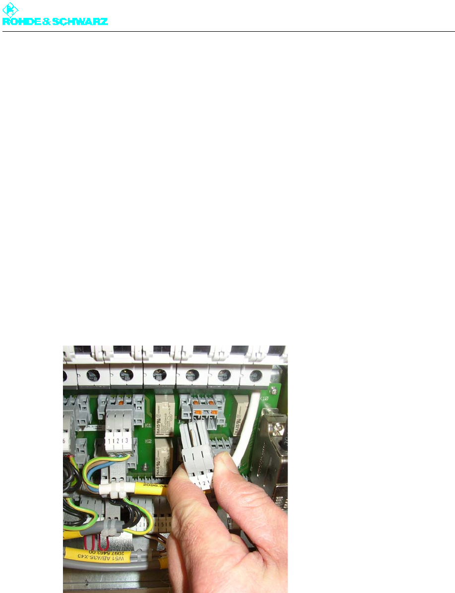
Chapter 3 Installation
2098.0188.72 - 3.12 - E-1
4.2 Connecting External Backup Fan
Note If conditions at the building site make it necessary to deal with larger distances (i.e. over
12 m), an external fan must be used.
The transmitter provides a switched phase for controlling an external contactor. Further-
more if necessary you can connect an external motor protection switch with alarm button
into the cooling disturbance circuit of the transmitter.
Switched phase for external fan
X33.1 = L (line protection 3A)
X33.2 = N
X33.3 = PE
Excess external cooling
44.1
44.2
Fig. 7 Male connector for connecting an external fan
4.3 Checking Ventilation Covers
To ensure that ventilation functions properly inside the transmitter, the interior part of the
transmitter rack has an opening on each side to permit air circulation.
Make sure that the ventilation covers on the slots in the frame where the amplifiers will
be fitted are open on both sides. Remove the covers if necessary.
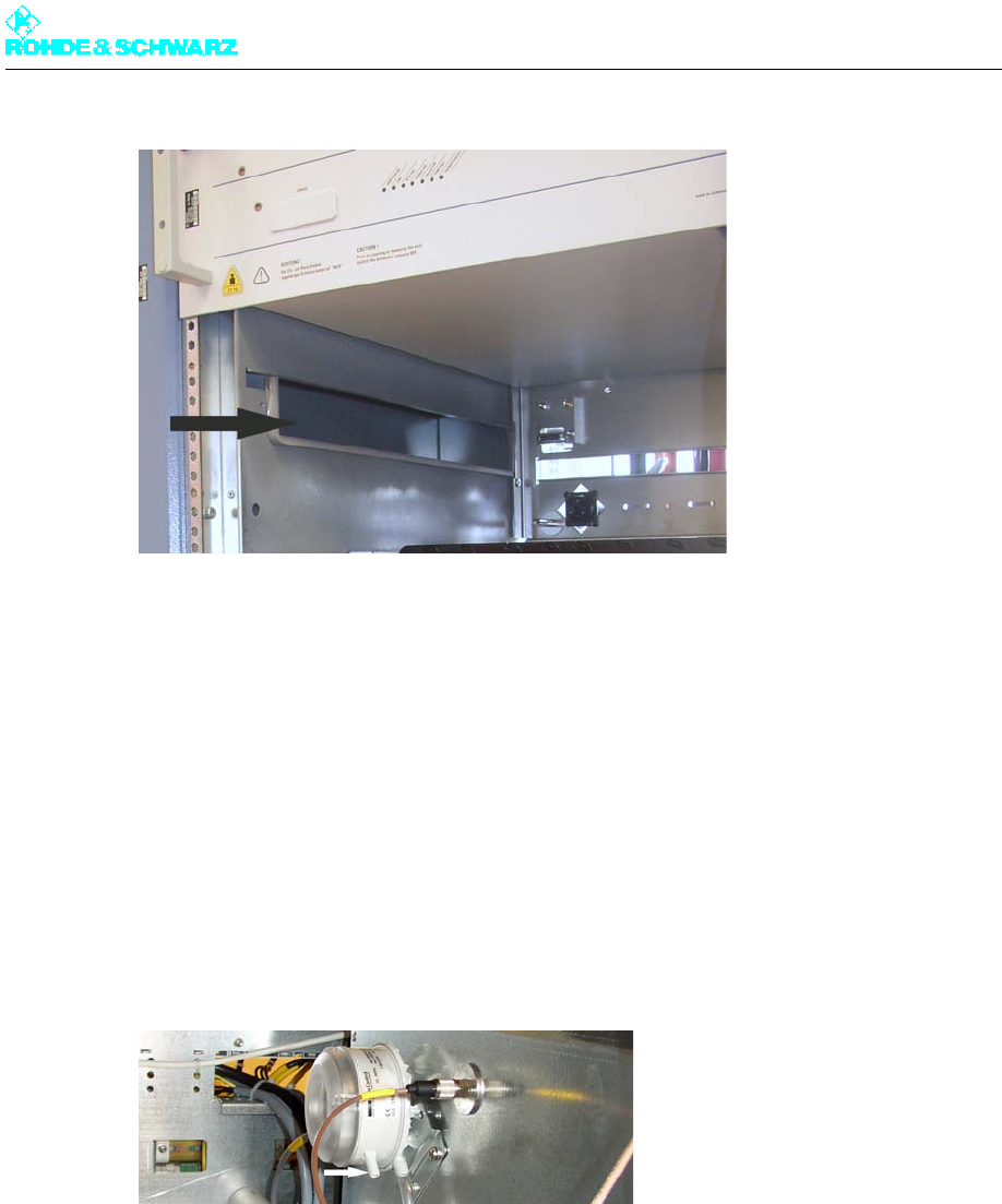
Chapter 3 Installation
2098.0188.72 - 3.13 - E-1
Fig. 8 Ventilation opening
Note The ventilation openings on vacant slots (without amplifiers) have to be closed.
4.4 Checking Differential Pressure Gages
For the differential pressure gages to be able to measure the pressure between the fans
and the environment, the covers must be removed.
Make sure that the covers of both differential pressure gages on the left side have been
removed.
Fig. 9 Differential pressure gage without cover
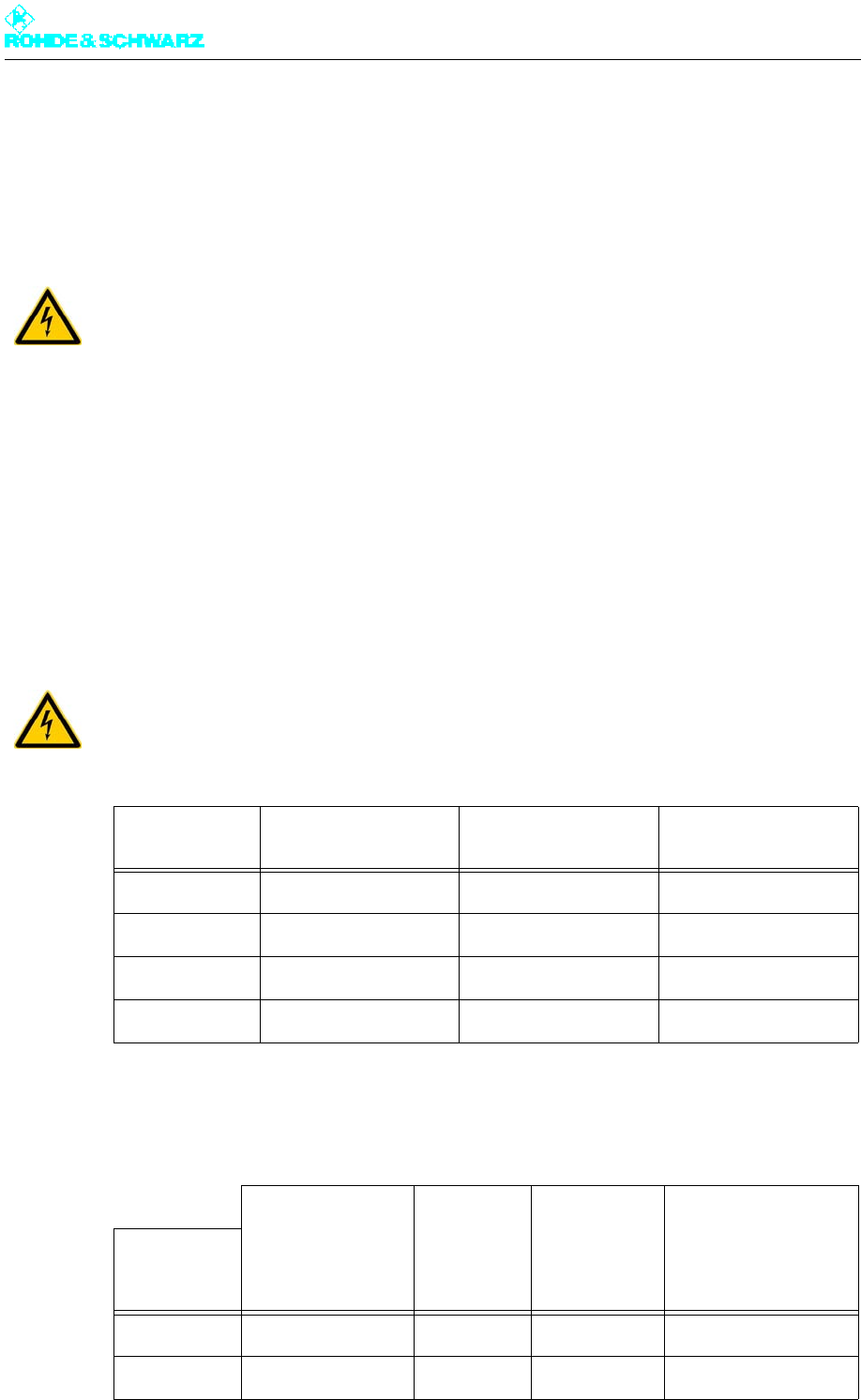
Chapter 3 Installation
2098.0188.72 - 3.14 - E-1
5 AC Power Supply
The standard components of the transmitter are fully cabled together. The rack therefore
simply needs to be connected to an external AC power supply.
General requirements
The AC power load of the transmitter is determined primarily by the number of amplifiers
and their output power. Furthermore, there is also a relationship between AC power con-
sumption and transmission frequency.
AC supply voltage – three-phase current 230 V/400 V ± 15 %
Power frequency 47 Hz to 63 Hz
DANGER!
Before you connect the transmitter, disconnect the external power supply cable from the
power supply.
WARNING!
Make sure that the AC supply voltage is within the specified range and check all power
cables for possible damage.
System type Power consumption a)
PAC (worst case) b)
a) Power specifications without optional equipment
b) The maximum power consumption by the transmitter occurs in channel 66.
Backup fuse
NH gG fuse Line cross-section
VDE / UL
R&S NV8301 2.8 kW 3 x 20 A 2.5 mm2 / AWG 12
R&S NV8302 4.9 kW 3 x 20 A 2.5 mm2 / AWG 12
R&S NV8303 7.0 kW 3 x 20 A 2.5 mm2 / AWG 10 c)
c) AWG 10 according to UL/CSA is needed due to I(undervoltage) > 16 A; asymmetrical power distribution due
to add-on equipment
R&S NV8304 10.0 kW 3 x 25 A 4.0 mm2 / AWG 10
Backup fuse Setting value Fixed value Line cross-section
System type Siemens auto-
matic line fuse,
e.g.
Overload
trip Short-circuit
trip VDE / UL
R&S NV8301 3VL17 02-1DD33... 16 A 300 A 2.5 mm2 / AWG 12
R&S NV8302 3VL17 02-1DD33... 16 A 300 A 2.5 mm2 / AWG 12
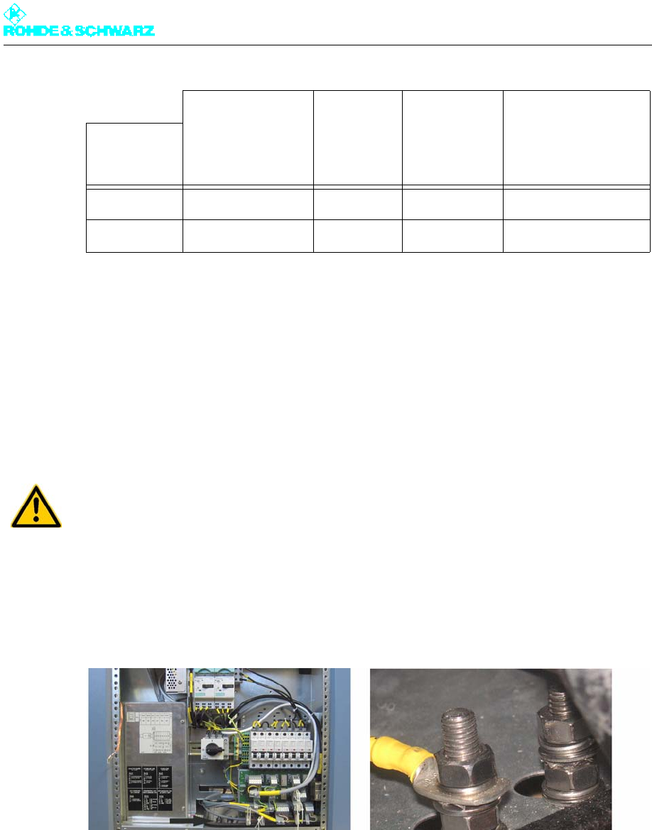
Chapter 3 Installation
2098.0188.72 - 3.15 - E-1
Note The recommended fuse ratings specified here apply to a power cable length of 20 m, a
maximum ambient temperature of 45 °C and a minimum undervoltage of 320 V. The default
setting of 5 A for the overcurrent tripping element at the motor protection switch MUST be
observed.
5.1 Connecting Transmitter Ground
A ground bolt is located on the bottom of the transmitter rack, and is easily accessible from
the front.
Secure the external ground conductor to the ground bolt using the ground nut.
Fig. 10 Ground connection on transmitter rack
5.2 Connecting AC Power Cable
The external power supply is connected for each rack directly to its main switch. The main
switch completely isolates the rack from the AC supply. The connection is made using a 5-
wire cable (three phases, neutral line, protective line).
R&S NV8303 3VL17 02-1DD33... 20 A 300 A 2.5 mm2 / AWG 10 a)
R&S NV8304 3VL17 03-1DD33... 25 A 300 A 4.0 mm2 / AWG 10
a) AWG 10 according to UL/CSA is needed due to I(undervoltage) > 16 A; asymmetrical power distribution due
to add-on equipment
WARNING!
The rack must be connected to the station's main ground terminal.
Backup fuse Setting value Fixed value Line cross-section
System type Siemens auto-
matic line fuse,
e.g.
Overload
trip Short-circuit
trip VDE / UL
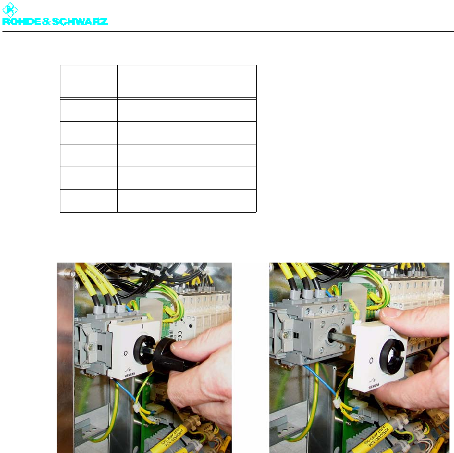
Chapter 3 Installation
2098.0188.72 - 3.16 - E-1
1. Unscrew the rotary switch and the cover of the main switch.
Fig. 11 Unscrew rotary switch and cover
2. Secure the supplied strain relief for the AC supply cable in place as shown.
AC power
supply Main switch Q1
L1 Q1.T1
L2 Q1.T2
L3 Q1.T3
NQ1.N
PE Grounding clamp X.PE1
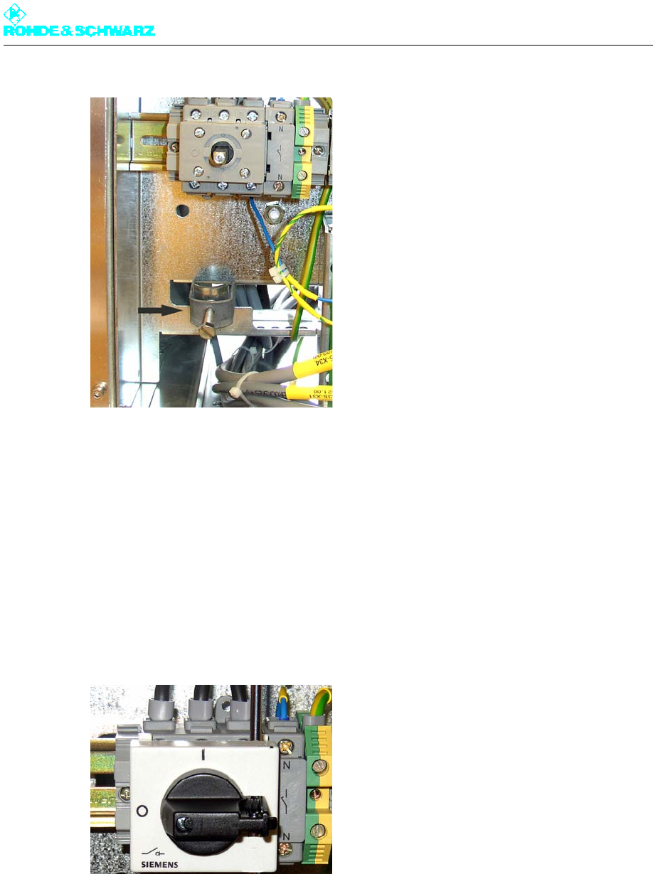
Chapter 3 Installation
2098.0188.72 - 3.17 - E-1
Fig. 12 Strain relief for the AC supply cable
3. Loosen the locking screws on the switch housing so that you can easily insert the ca-
bles.
4. Insert the cables into the corresponding openings and fasten them in place with screws.
5. Using a phase-sequence indicator, determine the phase sequence of the rotating field
(should be clockwise).
If the phase sequence is correct, continue to the next step. If the phase sequence is not
correct, reverse the cables and measure the phase sequence again.
6. Remount cover and rotary switch with screws.
Fig. 13 Main switch connection
5.3 Connecting External Equipment
You can connect the following equipment to the power distribution board on the transmitter:

Chapter 3 Installation
2098.0188.72 - 3.18 - E-1
External fan to X33 (see section "Connection of External Backup Fan")
External dummy antenna to X41 (see section "Connecting Dummy Antenna")
Suitably adapted dummy plugs are located at the points provided for the purpose.
1. Take the required dummy plug from the power distribution board.
2. Connect the cable of the external device to the plug connector.
3. Put the plug connector back into the power distribution board.
Fig. 14 Power distribution board with dummy plugs
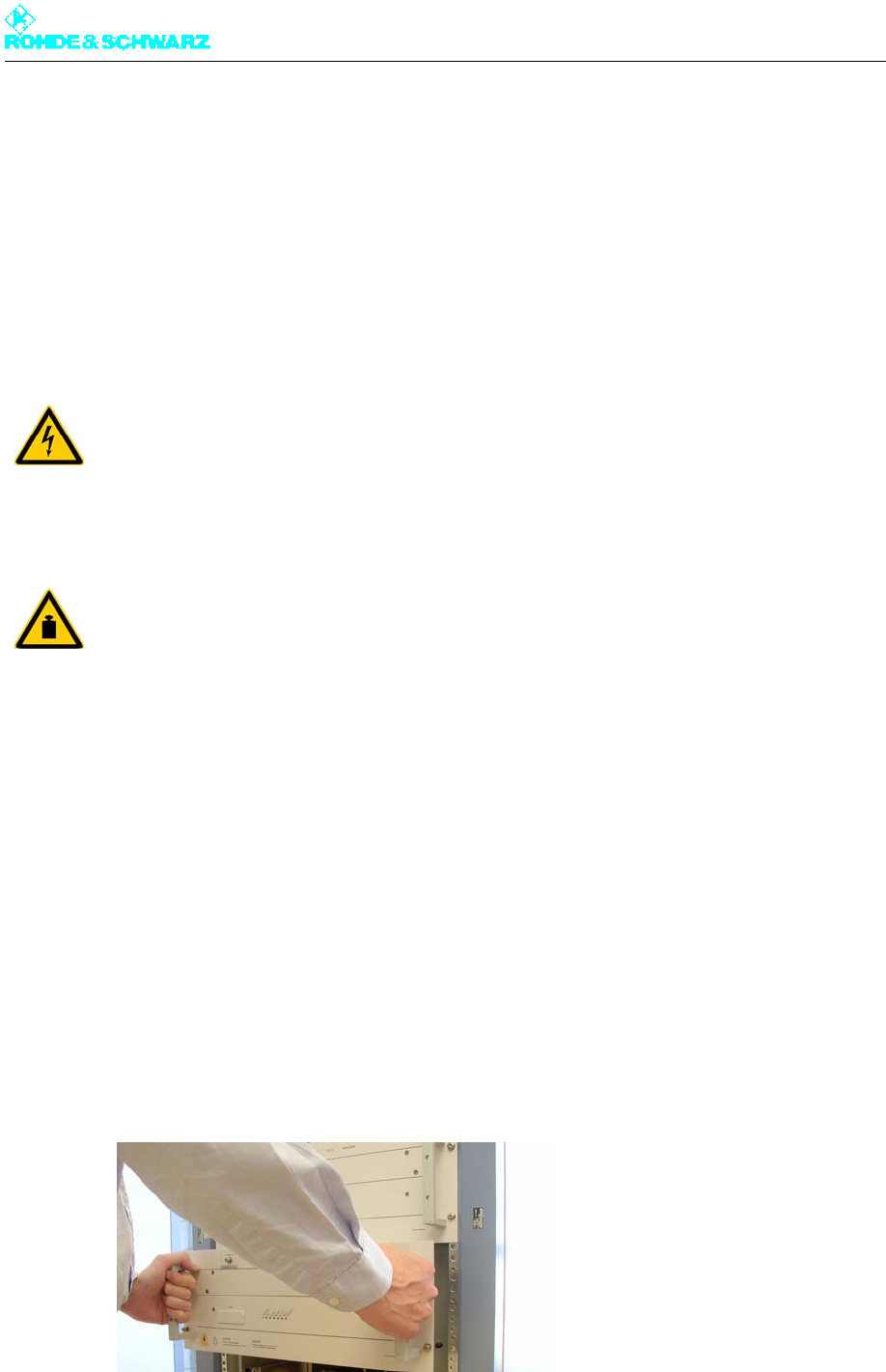
Chapter 3 Installation
2098.0188.72 - 3.19 - E-1
6 Amplifiers
When the transmitter is delivered, one or two exciters and an R&S NetCCU800 are already
mounted in the rack. The amplifiers, however, are not and must be retrofitted in the rack.
6.1 Installing Amplifiers
Note Before installing the amplifier, make sure that the ventilation covers on the amplifier slots
provided in the frame are open on both sides. Remove the covers if necessary.
Note It is advisable to install the amplifiers in sequence starting at the top and working down to
the bottom.
Install the amplifiers as follows:
1. Carefully remove the amplifier from its packaging.
2. Select the installation position provided for the amplifier in the transmitter rack.
3. Place the amplifier on the guide rails and slide it carefully into the rack as far as it will go.
The amplifier is guided onto the connections by means of guide pins on the rear panel.
4. Secure the amplifier in place using the 4 screws of the two front brackets on the rack.
5. To install additional amplifiers, repeat steps 1 to 4.
Fig. 15 Installing an amplifier
WARNING!
Always make sure that the power supply is disconnected before commencing any installa-
tion work on the transmitter rack. This will prevent injury caused by electric shock and
damage to the instruments.
CAUTION!
Always have a second person assist you in installing the amplifiers as the instruments are
very heavy (approx. 28 kg).

Chapter 3 Installation
2098.0188.72 - 3.20 - E-1
7 Connecting Antenna/Dummy Antenna to RF
Connector
The connection flanges for the antenna cables are uniformly 1 5/8“ EIA for TV transmitters
in the R&S NV8300 family. These flanges are located on the roof of the transmitter. Depend-
ing on the transmitter station (one or more transmitters), either the antenna (RF cable or RF
transmission line) or an RF connection is connected directly to a multiple combining filter.
7.1 Connecting Antenna
Connect the antenna as follows:
Using the 4 screws (M8, 35 mm), secure the coaxial cable preassembled on the station
to the EIA flange of the transmitter's RF output. To prevent the screw connection from
loosening, insert a plain washer and a spring-lock washer.
Note In regions with high humidity, the supplied rubber ring can be inserted into the groove be-
tween the two EIA flanges.
ATTENTION!
You should not connect the antenna until you have completed all measurements.
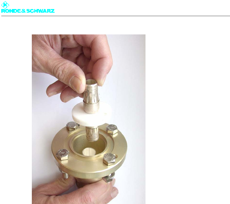
Chapter 3 Installation
2098.0188.72 - 3.21 - E-1
Fig. 16 RF connection with adapter
7.2 Connecting Dummy Antenna
The dummy antenna is only connected when putting the system into operation or for main-
tenance and repair purposes.
With some dummy antennas that have coolant monitoring and overtemperature monitoring,
the monitoring equipment can be connected to the transmitter. The main protection loop
(X41.1 and X41.2 in the power distribution) can be used here as a temporary measure (e.g.
while the unit is being put into operation).
1. To connect the main protection loop, use the inserted jumper plug and remove the jump-
er.
2. Connect the monitoring cable in place of the jumper.
If you are using an RF patch panel that allows you to switch between the antenna and dum-
my antenna by means of an RF U-link connector (permanent installation), you should con-
nect the dummy antenna monitoring unit to the standby protection loop (X41.3 and X41.4
in the power distribution). This requires the patch panel messages to be additionally con-
nected to the R&S NetCCU800 transmitter control unit (X12.15 antenna message or X12.3
dummy antenna message, to X12.16 GND). Activation of the dummy antenna (via X33 in
the power distribution) is then also active.
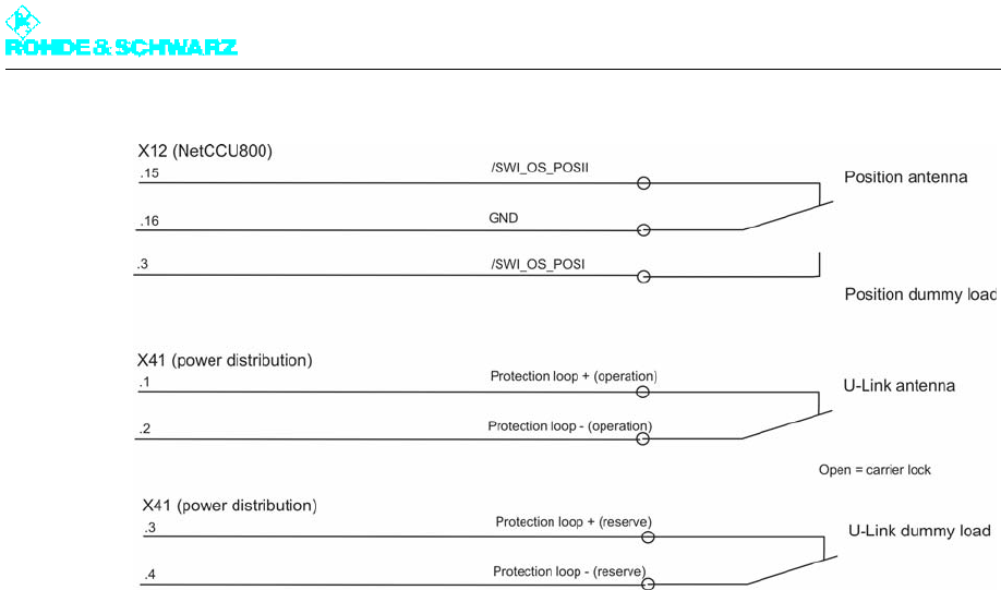
Chapter 3 Installation
2098.0188.72 - 3.22 - E-1
Fig. 17 Looping in an antenna patch panel
Chapter 3 Installation
2098.0188.72 - 3.23 - E-1
8 Connection Panel
The following table lists all the connectors that you may need to assign.
Connection Description
CANBUS X101A CAN bus data connection for additional racks or output stage A
CANBUS X101B CAN bus data connection for additional racks or output stage B
RS232 X232 Serial data connection for external BITBUS interface
ETHERNET Remote LAN connector or system LAN connector, e.g. for N+1
ANTENNA 1 INPUT Antenna connection for receiver module input 1 in R&S NetCCU800
(DVB-T only)
ANTENNA 2 INPUT Antenna connection for receiver module input 2 in R&S NetCCU800
(DVB-T only)
TS1 / TS2 Transport stream inputs
TS3 / TS4 Additional connections for TS1 and TS2 with hierarchical coding
(DVB-T only)
10 MHz REF INPUT Input for 10 MHz reference for synchronization of output signal
1PPS MONITORING Test output 1PPS (1PPS = 1 pulse per second)
1PPS EXT INPUT Input for 1PPS signal, reference signal in SFN mode
TS1/2 MONITORING Monitor output for selected TS signal of inputs 1 and 2
TS3/4 MONITORING Monitor output for selected TS signal of inputs 3 and 4 (DVB-T only)

Chapter 3 Installation
2098.0188.72 - 3.24 - E-1

Broadcasting Division
2095.7346.32 - 4.0 - E-1
CHAPTER 4
COMMISSIONING
Printed in Germany

Chapter 4 Commissioning
2098.0188.72 - 4.01 - E-1
CONTENTS
1 General Information ......................................................................... 1
1.1 Preparations ....................................................................................................1
1.2 Requirements ..................................................................................................2
1.3 Operating R&S NetCCU800 ...........................................................................2
2 Preparing for Transmitter Startup .................................................. 3
2.1 Preparing for Local Operation .......................................................................3
2.2 Checking and Setting System and Operating Parameters .........................3
2.3 R&S NetCCU800 .............................................................................................3
2.3.1 Switching On R&S NetCCU800 ...................................................................3
2.3.2 Changing User Type ....................................................................................3
2.3.3 Entering Basic Settings ................................................................................4
2.3.4 Setting Date and Time ..................................................................................5
2.3.5 Adjusting Network Settings ..........................................................................6
2.3.5.1 Front Ethernet Interface ..................................................................................... 6
2.3.5.2 Rear Ethernet Interface (NETLINK) ................................................................... 7
2.4 Setting Transmitter Type ...............................................................................9
2.5 Entering Exciter Settings .............................................................................11
2.5.1 Setting TV Standard ...................................................................................11
2.5.2 Configuring Input Interfaces .......................................................................12
2.5.2.1 Specifying Data Format for Data Streams Input 1 and Input 2 ......................... 12
2.5.2.2 Setting Automatic Input Switchover .................................................................. 13
2.5.3 Switching Off Precorrector .........................................................................14
2.5.4 Setting Transmitter Frequency ...................................................................15
2.5.5 Adjusting the I/Q Modulator ........................................................................16
2.5.6 Setting RF Output .......................................................................................17
2.5.7 Specifying Behavior on Failure of a Reference Source ..............................18
2.6 Entering Output Stage Settings ..................................................................19
2.6.1 Setting Up Output Stage ............................................................................19
2.7 Setting Transmitter Output Power ..............................................................21
2.8 Calibrating Power Displays .........................................................................22
2.8.1 Calibrating Forward and Reflected Power Displays ...................................22
3 Completion of Startup Procedure ................................................ 26

Chapter 4 Commissioning
2098.0188.72 - 4.02 - E-1
3.1 Final Steps ....................................................................................................26
3.1.1 Checking R&S NETCCU800 Status Display ..............................................26
3.1.2 Checking Exciter Status Display ................................................................27
3.1.3 Checking Output Stage Status Display ......................................................27
3.2 Adjusting Amplifier Order Numbers to Installation Positions in Rack ....29
3.3 Clearing Event Memory ................................................................................30
4 Precorrection ................................................................................. 31
4.1 Functions of Nonlinear Precorrector ..........................................................31
4.1.1 General .......................................................................................................31
4.1.2 Linear Basic Precorrection .........................................................................31
4.1.3 Nonlinear Frequency Responses ...............................................................32
4.1.4 Dynamic Precorrection (ATV Split Only) ....................................................32
4.1.5 Audio Phase Precorrection (ATV Combined Only) ....................................32
4.2 General Information on Operating Precorrector .......................................32
4.3 Performing Precorrection ............................................................................32
4.3.1 General Requirements ...............................................................................33
4.3.2 Determining System Levels ........................................................................33
4.3.3 Precorrection Procedure ............................................................................34
4.3.3.1 Starting Precorrection ....................................................................................... 34
4.3.3.2 Phase Precorrection ......................................................................................... 35
4.3.3.3 Amplitude Precorrection ................................................................................... 36
4.3.3.4 Frequency-Dependent Precorrection ............................................................... 37
4.3.3.5 Fine Adjustment Using an Existing or Preset Characteristic ............................ 39

Chapter 4 Commissioning
2098.0188.72 - 4.1 - E-1
1 General Information
Transmitters are put into operation by means of the graphical user interface of the R&S
NetCCU800.
1.1 Preparations
Before you can put a transmitter into operation, it must first have been fully installed. Check
the following list to ensure that all connections have been correctly made:
Check whether all the modules delivered have been correctly installed and connected
as necessary.
Check whether the transmitter has been correctly connected to the AC supply. Please
note:
Connection in general
– Power feed, rack ground, air cooling system, 50 test load (dummy antenna) in ap-
propriate cases, power-handling capacity P > nominal transmitter power, directional-
coupler filter, matrix or antenna
Connections involving RF carrier loops and fault messages
– Set up the following jumpers/connections on the power distribution board connectors
(the name of the connector concerned is printed on the board).
RF carrier loop in operation - X41 1-2
RF Carrier loop on standby - X41 3-4
Fault message for rack absorber - X42 1-2
Fault message for system absorber - X42 3-4
(In the case of multi-rack transmitters the overtemperature switches of the respective
RF absorbers are connected to the absorber fault message inputs.)
Fault message for external cooling - X44 1-2
If customer instruments having interlock circuit outputs such as control monitoring
are present, you can loop in these instruments in place of the wire jumpers.
Emergency-off switch X7 (if available)
Motor protection switches to be set at 5 A
Check the phase sequence of the AC supply voltage.
Switch off the main disconnect switch Q1, together with all motor protection switches
and automatic line fuses.
Check that all screws and nuts are securely fastened, especially those on the transmitter
RF output.

Chapter 4 Commissioning
2098.0188.72 - 4.2 - E-1
1.2 Requirements
1. Before switching on the transmitter, check whether the exciter is set to the correct fre-
quency (consistent with any diplexer or bandpass filter that may be connected).
If the transmission frequency is not yet known, the transmitter should remain switched
off until the frequency is set.
2. Connect an antenna to the RF output.
Switching on transmitter
Switch on the transmitter as follows:
1. Switch on the main switch (Q1).
2. Switch on the exciter (F1 or F2).
The exciter boots up.
3. Switch on the R&S NetCCU800 (F3).
The R&S NetCCU800 boots up.
4. Switch on the auxiliary power supply unit (F5).
5. Switch on the fan fuse for fan 1 (F6) and for fan 2 (F7).
6. If necessary, switch on additional units (F4) and peripheral units (F8).
1.3 Operating R&S NetCCU800
Note Detailed information on operating the R&S NetCCU800 can be found in the chapter "Oper-
ating".

Chapter 4 Commissioning
2098.0188.72 - 4.3 - E-1
2 Preparing for Transmitter Startup
Local operation of the R&S NetCCU800 includes all the information calls for the system pa-
rameters and their settings, complete with intuitive graphical menus.
Remote operation via a web browser is possible only if a PC or notebook is connected to
the front panel of the R&S NetCCU800.
2.1 Preparing for Local Operation
To prepare for local control, proceed as follows:
Press the LOCAL key on the R&S NetCCU800.
Its yellow LED should light up.
2.2 Checking and Setting System and Operating
Parameters
In order to bring the transmitter into operation, you must check and set the following system
and operating parameters.
2.3 R&S NetCCU800
2.3.1 Switching On R&S NetCCU800
Connect the R&S NetCCU800 to the AC power supply.
After a few seconds, the unit boots up and the entry screen indicates when it is ready for
use.
Local operation of the R&S NetCCU800 includes all the information calls for the system pa-
rameters and their settings, complete with intuitive graphical menus.
Remote operation via a web browser is possible only if a PC or notebook is connected to
the front panel of the R&S NetCCU800.
2.3.2 Changing User Type
To configure the transmitter by means of the R&S NetCCU800, you must have configuration
rights.
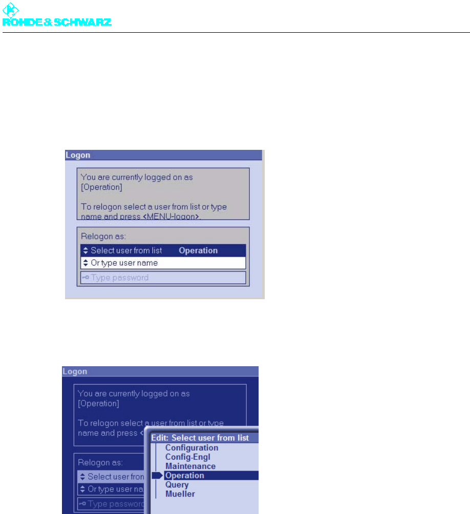
Chapter 4 Commissioning
2098.0188.72 - 4.4 - E-1
To log on with configuration rights under local control, proceed as follows:
1. From the context menu, select the menu item Change User.
The Logon window opens. The current user ID is displayed to the right of Select user
from list.
2. Under Select user from list, select the user ID Configuration.
After confirming with OK, you are logged on again with configuration rights.
Note No password is required to change the user ID under local control (according to the factory
default).
2.3.3 Entering Basic Settings
After switching on the R&S NetCCU800, the basic system settings can be entered.
1. Select NetCCU > Setup > NetCCU Setup > Common.
The Common window opens.
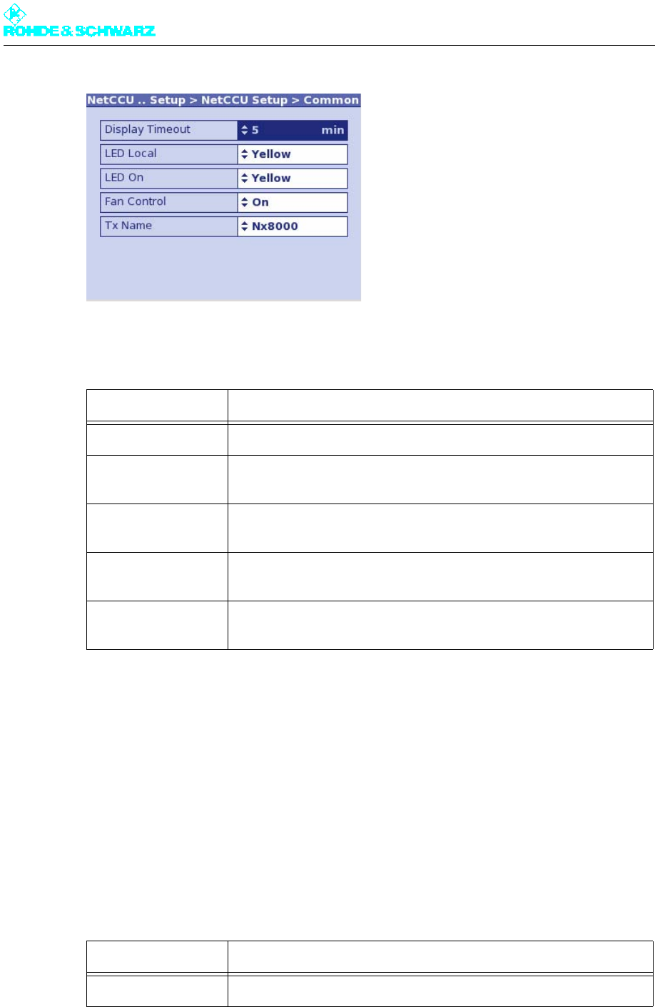
Chapter 4 Commissioning
2098.0188.72 - 4.5 - E-1
2. Enter the basic settings as shown in the table below.
2.3.4 Setting Date and Time
The date and precise time are required to make correct logbook entries. This information is
supplied by the internal clock of the R&S NetCCU800. If necessary, the time and date can
be corrected in the Date/Time menu window.
Using NTP
You can change directly to the NTP menu window from the context menu. With NTP, the
local time is determined via NTP and a time set manually under Local Time is overwritten.
Function Explanation
Display Timeout Time in minutes after which the display switches off (standby)
LED Local Color of the Local LED on the front panel of the R&S NetCCU800 (yel-
low, green)
LED On Color of the ON LED on the front panel of the R&S NetCCU800 (yellow,
green)
Fan Control Used to switch the fan monitoring function on and off; the fan monitoring
function must be switched off for instruments without fans.
Tx Name User-definable name for the transmitter; is displayed in the login screen
and in the browser window
Function Explanation
Setup NTP Used to change directly to the NTP menu window
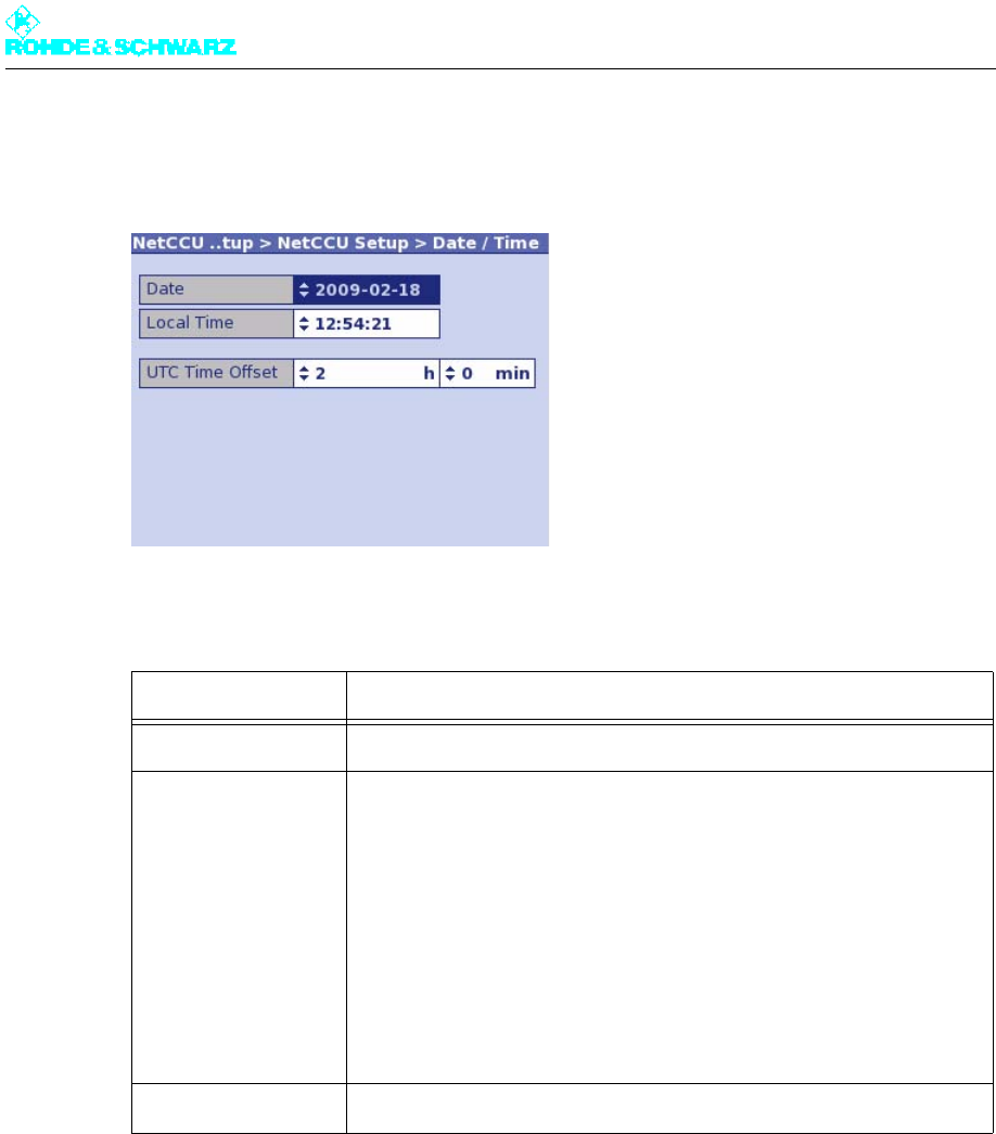
Chapter 4 Commissioning
2098.0188.72 - 4.6 - E-1
1. Select NetCCU > Setup > NetCCU Setup > Date/Time.
The Date/Time window opens.
2. Enter the basic settings as shown in the table below.
2.3.5 Adjusting Network Settings
In the windows of the Network menu, you can make network settings and obtain informa-
tion about current settings.
2.3.5.1 Front Ethernet Interface
The ETHERNET interface on the front panel of the R&S NetCCU800 is used to connect a
PC/laptop. Find out about the factory settings for this interface if you want to operate the
transmitter "remotely" using a connected PC.
Setting item Explanation
Date Used to set the current date
Local Time Used to set the local time
The local time is the time of day or zone time applicable at the station.
Unlike universal time (UTC = universal time coordinated), there is a pos-
itive offset for time zones east of Greenwich or a negative offset for time
zones west of Greenwich.This offset is determined by the time zone and
is always a multiple of a full hour or sometimes of a half hour.
In some countries, the clock is set forward by 1 hour in summer (daylight
saving time). The time offset relative to UTC then changes correspond-
ingly.
UTC Time Offset Used to enter the time offset between local time and UTC
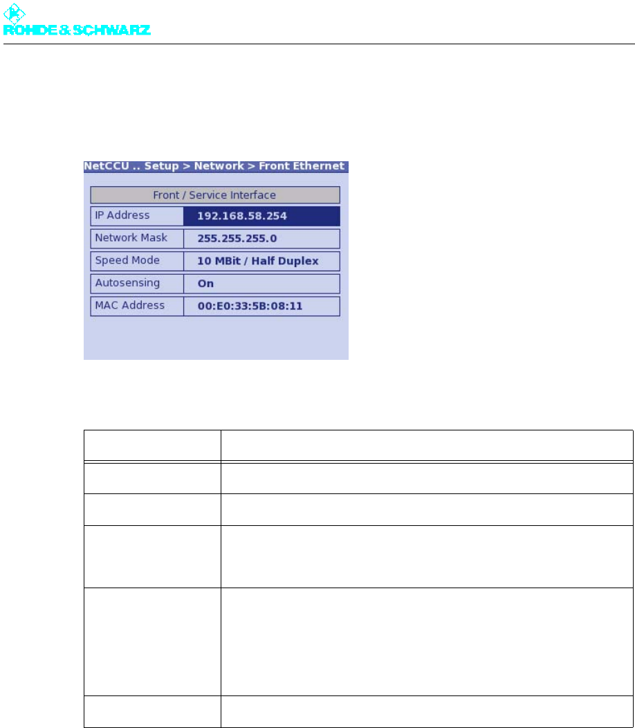
Chapter 4 Commissioning
2098.0188.72 - 4.7 - E-1
Select NetCCU > Setup > NetCCU Setup > Network > Front Ethernet.
The Front Ethernet window opens.
The Front Ethernet window displays the following network settings:
Notes
All settings for the front Ethernet interface are preset. If a PC/laptop is to be connected, the
network interface on the PC/laptop must be configured accordingly:
– IP address (PC): First three segments same as those for IP Address of the R&S
NetCCU800 (see above); a value below 250 must be entered for the last segment
– Subnet mask (PC): Same settings as under Network Mask (see above)
2.3.5.2 Rear Ethernet Interface (NETLINK)
Configure the NETLINK interface (X5) on the rear panel of the R&S NetCCU800 if you want
to connect the transmitter to a LAN/WAN.
Display Explanation
IP Address IP address of the network card
Network Mask Subnet mask of the network card
Speed Mode Speed and duplex
Factory setting: 10 Mbit / half duplex
Autosensing Autonegotiation ON/OFF
Factory setting: On
Autonegotiation = Automatic determination of the settings for the net-
work card
MAC Address Unique ID of the network card
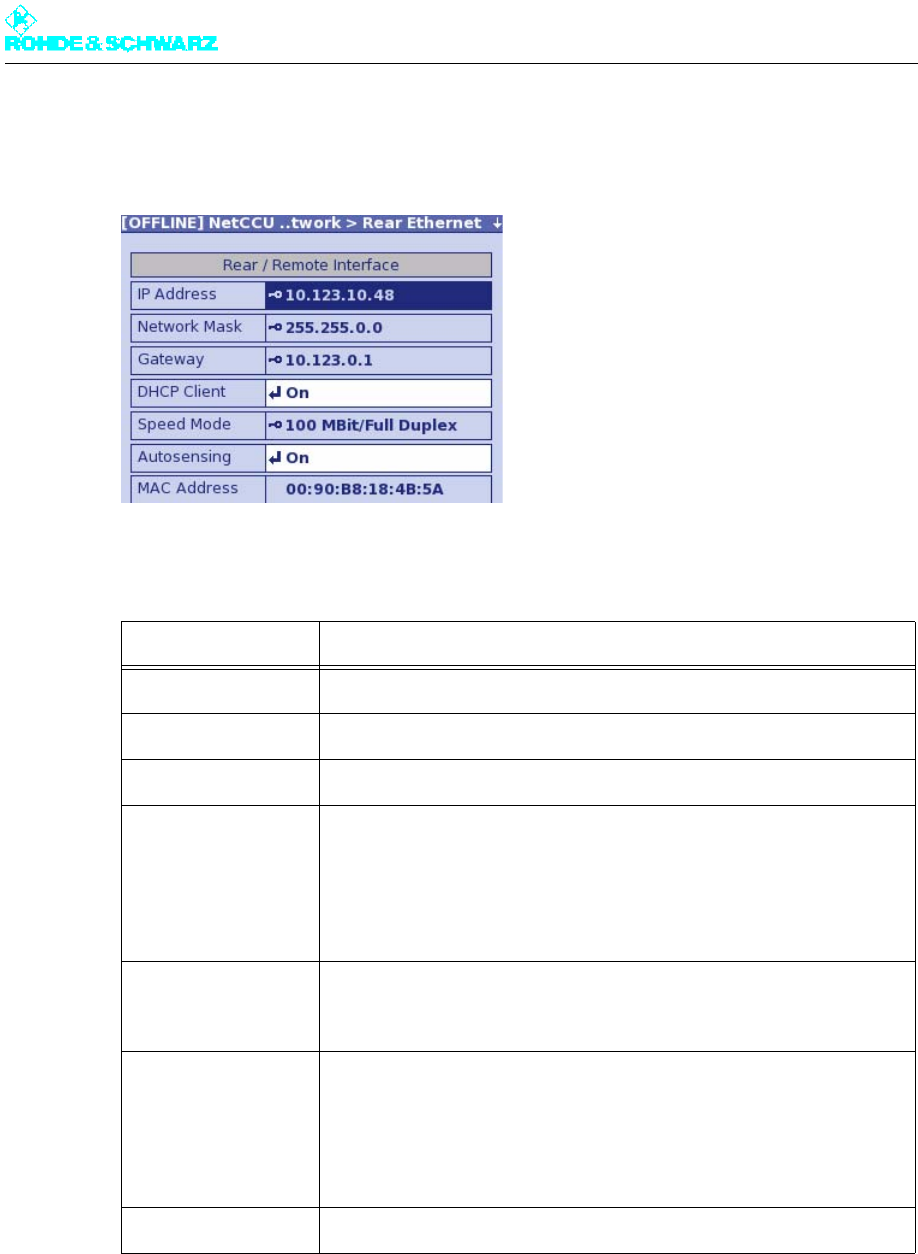
Chapter 4 Commissioning
2098.0188.72 - 4.8 - E-1
1. Select NetCCU > Setup > NetCCU Setup > Network > Rear Ethernet.
The Rear Ethernet window opens.
2. Make the required settings:
Setting/display Explanation
IP Address IP address of the network card
Network Mask Subnet mask of the network card
Gateway Gateway address (specified by the network administrator)
DHCP Client Switch used to activate/deactivate the DHCP client:
– On: The network settings for IP address, subnet mask and gateway
are retrieved automatically by a DHCP server
– Off: The network settings for IP address, subnet mask and gateway
must be entered manually (see above)
Speed Mode a)
a) Caution: Only change the settings for Speed Mode and Autosensing in exceptional cases where there are
problems with the network connection.
Speed and duplex
Factory setting: 100 Mbit / full duplex
Autosensing a) Autonegotiation ON/OFF
Factory setting: On
Autonegotiation = Automatic determination of the settings for the net-
work card
MAC Address Unique ID of the network card
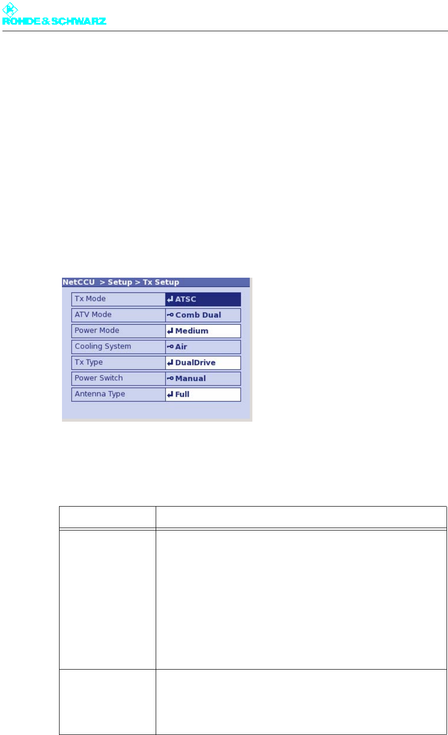
Chapter 4 Commissioning
2098.0188.72 - 4.9 - E-1
Notes
– Manual settings for remote connection should only be entered in offline mode (context
menu: Edit Offline) and then activated with Submit Changes (context menu).
– The IP address must not be in the same network as the front ETHERNET interface.
– To allow automatic integration in a network (DHCP Client activated), the network must
contain a DHCP server.
2.4 Setting Transmitter Type
Select NetCCU > Setup > TX Setup.
The Tx Setup window opens.
You can use the Tx Setup window to make system-specific settings and to define standby
behavior.
The table below describes the adjustable parameters:
Function Explanation
Tx Mode Used to select the transmitter standard
– NoExciter: R&S NetCCU800 is operated as a standalone instrument
(e.g. in combination with the DVB-T receiver module option)
– Multi: Both exciters in a transmitter use different standards
– FM: Analog sound broadcasting standard
– ATV: Analog TV standard
– ATSC: Digital TV standard (USA)
– DAB: Digital audio broadcasting standard
– DVB: Digital TV standard (Europe)
– DTMB: Digital TV standard (South America, Asia, Europe)
– MediaFLO™: Digital TV standard (USA)
– ISDB-T: Digital TV standard (Brazil, Japan)
ATV Mode Selection only possible if ATV is set under Tx Mode
– Comb Single: Vision signal and sound signal are transmitted via one
amplifier (same channel) (single = 1 sound carrier)
– Comb Dual: Vision signal and sound signal are transmitted via one
amplifier (same channel) (dual = 2 sound carriers)

Chapter 4 Commissioning
2098.0188.72 - 4.10 - E-1
Basic setup of transmitter standby systems
Power Mode Used to set the power class
– Low
– Medium
– High
Cooling System Used cooling system
The following setting is preset for Power Mode "Low" or "Medium":
– Air: Air cooling
The following settings can be selected for Power Mode "High":
– Liquid: Transmitter is connected to an external cooling system which
is used to cool the entire station
– Liquid PUC: Transmitter has its own cooling system (R&S ZK810)
Tx Type Used to set the standby behavior:
– Single TX: Standby system (see below)
– Dual Drive: Standby system (see below)
– Passive PA: Standby system (see below)
– Active PA: Standby system (see below)
Power Switch Used to set the hardware configuration for antenna switchover. The fol-
lowing options are available:
– "Manual" for manual antenna switchover
– "Automatic" for electronic antenna switchover
Antenna Type Country-specific setting for the antenna type; the default setting is Full
Transmitter standby system Setting:
Tx Type Setting:
Power Switch
Single transmitter system (without standby) Single Tx Manual
2 exciters / 1 output stage;
if one exciter fails, switchover to second exciter
Dual Drive Manual
2 exciters / 2 output stages;
if one exciter or output stage fails, switchover
to other exciter or output stage
Passive PA Automatic
2 exciters / 2 output stages;
if one output stage fails, transmission at half
power (failure of an exciter has no negative
consequences)
Active PA Manual / Automatic
Function Explanation
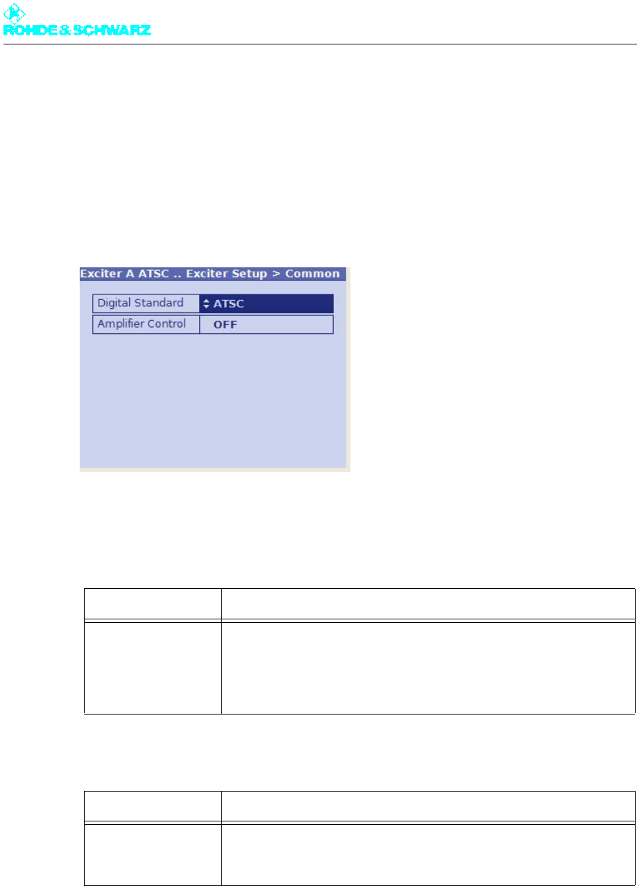
Chapter 4 Commissioning
2098.0188.72 - 4.11 - E-1
2.5 Entering Exciter Settings
2.5.1 Setting TV Standard
1. Select Exciter A ATSC > Setup > Exciter Setup > Common.
The Exciter Setup > Common window opens.
2. Select the required TV standard.
The table below describes the parameters in detail:
Setting item Description
Digital Standard Selection of the digital TV standard: DVB-T, DVB-H or ATSC
To switch over from DVB-T or DVB-H to ATSC you need to reboot a) the
exciter. At the same time signal processing is switched over and the
associated user interface is loaded.
a) To reboot the exciter, disconnect it briefly from the AC power supply or execute the Reboot Tx command in
the Tx Setup context menu.
Display Description
Amplifier Control Status display for amplifier control
In R&S low-power transmitters, the exciter takes over amplifier control.
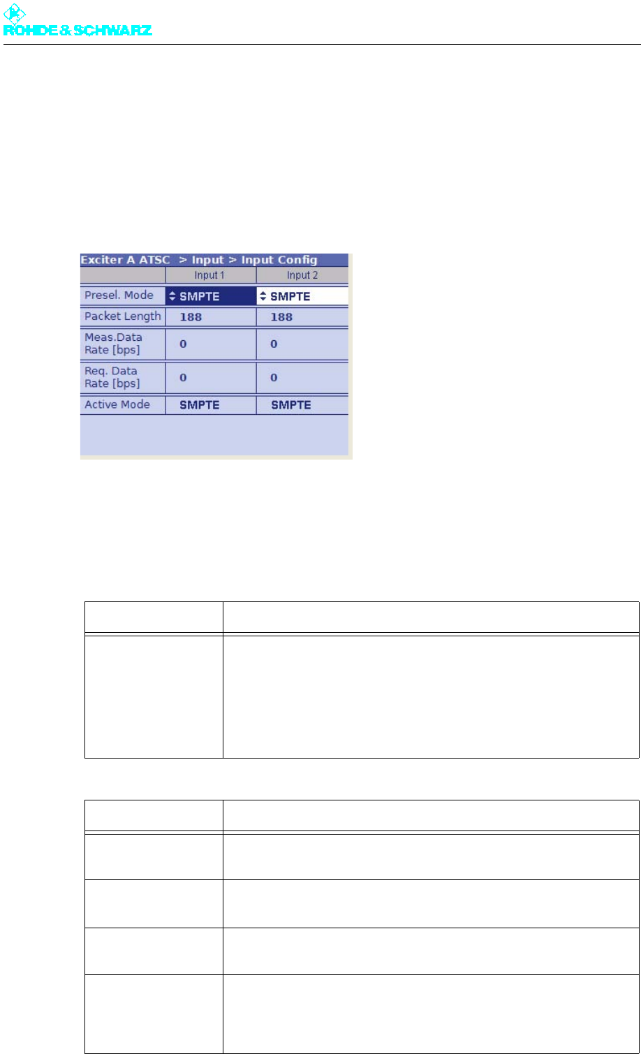
Chapter 4 Commissioning
2098.0188.72 - 4.12 - E-1
2.5.2 Configuring Input Interfaces
2.5.2.1 Specifying Data Format for Data Streams Input 1 and Input 2
1. Select Exciter A ATSC > Input > Input Config.
The Input > Input Config window opens.
2. Go to Presel. Mode and select the value Auto for Input1 and Input2.
The data format is recognized automatically.
The table below describes the parameters in detail:
Setting item Explanation
Presel. Mode
[Input 1/Input 2]
Sets the data format for the two data streams (main and standby sig-
nals) on inputs TS 1 IN or TS 2 IN.
The options are as follows:
– AUTO: The data format is recognized automatically
– ASI: Manual setting for an ASI transport stream
– SMPTE: Manual setting for an SMPTE transport stream
Display Explanation
Packet Length
[Input 1/Input 2]
Displays the packet length detected at the respective input
Meas.Data Rate [bps]
[Input 1/Input 2]
Displays the data rate measured at the respective input without null
packets
Req. Data Rate [bps]
[Input 1/Input 2]
Display for checking the measured data rate. The maximum data pro-
cessing rate is displayed.
Active Mode Displays the data format detected or set at the respective input:
– ASI: As described
– SMTPE: As described
– AUTO: Auto is selected and there is no data stream
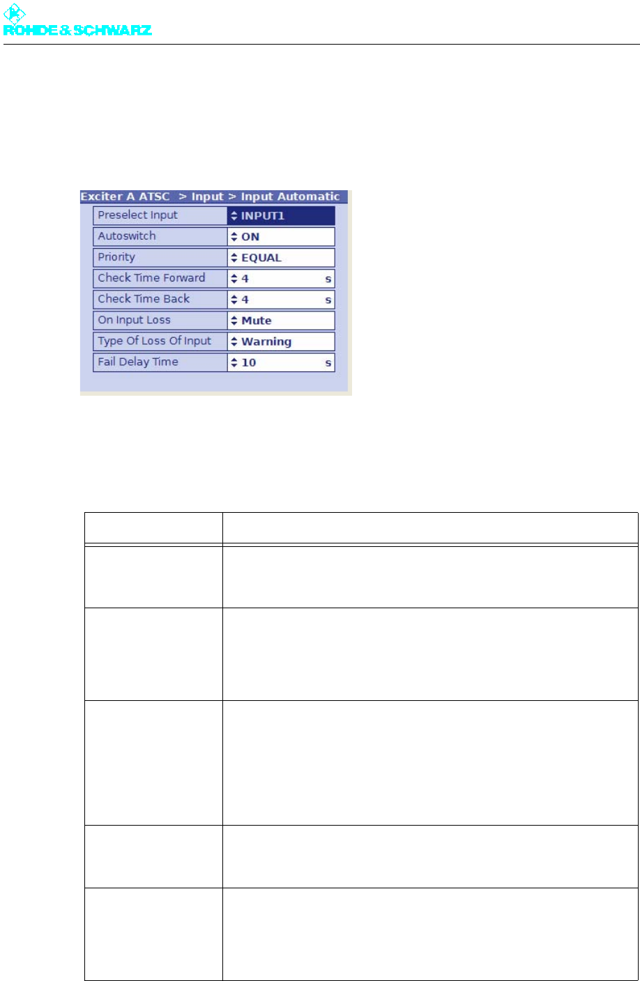
Chapter 4 Commissioning
2098.0188.72 - 4.13 - E-1
2.5.2.2 Setting Automatic Input Switchover
1. Select Exciter A ATSC > Input > Input Automatic.
The Input > Input Automatic window opens.
2. Activate automatic input switchover if required, and enter the appropriate settings.
The table below describes the parameters in detail:
Setting item Description
Preselect Input Preselection of inputs
– INPUT 1: Operating input is TS 1 IN.
– INPUT 2: Operating input is TS 2 IN.
Autoswitch Activates and deactivates automatic input switchover
In the event of a failure on the active operating input, automatic switcho-
ver to the standby input takes place. The automatic switchover mode is
defined by the following parameter settings.
Priority Selects the priority mode
– EQUAL: The preselected operating input and standby input have the
same priority. Once a switchover has taken place the system does not
normally switch back to the previously faulty operating input.
– PRIO: The preselected operating input is the priority input. Once a
switchover has taken place the system switches back to the prese-
lected operating input as soon as the signal reappears.
Check Time Forward For setting a delay time (0 to 60 s) which must elapse before the
switchover to the standby input takes place in the event of a failure on
the operating input
Check Time Back For setting a delay time (0 to 60 s) which must elapse before switching
back to the preselected operating input after switching over from the
standby input (which is no longer active)
The function has no effect if the priority mode is set to EQUAL.
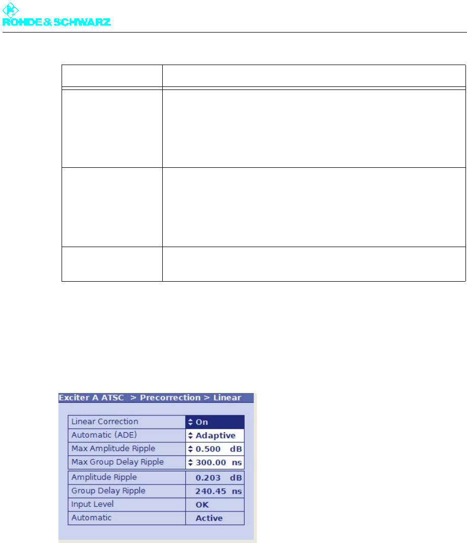
Chapter 4 Commissioning
2098.0188.72 - 4.14 - E-1
2.5.3 Switching Off Precorrector
1. Select Exciter A ATSC > Precorrection > Linear.
The Linear window opens.
2. Set Linear Correction to Off.
The linear precorrector path is deactivated.
3. Select Exciter A ATSC > Precorrection > Nonlinear.
The Nonlinear window opens.
On Input Loss For setting the behavior in the event of a defective input signal (synchro-
nization error)
– No Mute: The output signal is not suppressed (only effective with
MFN)
– Mute: The output signal is suppressed if the data rate is incorrect (rec-
ommended for SFN)
Type of Loss of Input Selection:
– Warning: If the input signal fails, only a warning will be generated.
– Fault: If the input signal fails, an additional sum fault will be generated
after the time set under Fail Delay Time has elapsed. In the case of
transmitters with exciter standby, switchover to the second exciter
occurs.
Fail Delay Time For setting a delay time which must elapse after an input signal dropout
before a general fault is generated.
Setting item Description
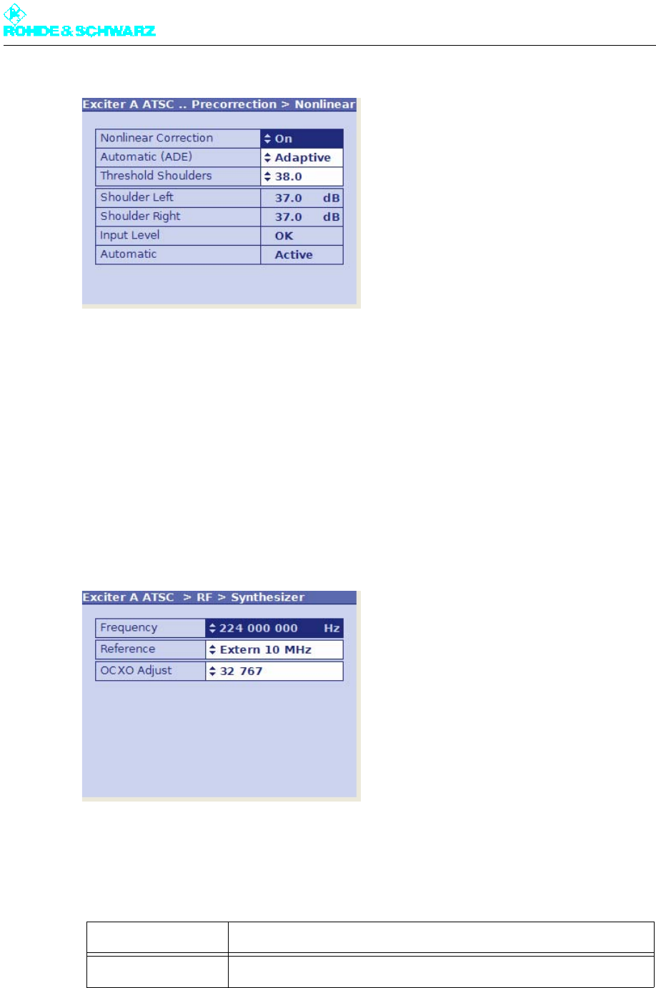
Chapter 4 Commissioning
2098.0188.72 - 4.15 - E-1
4. Set Nonlinear Correction to Off.
The nonlinear precorrector path is deactivated.
Note The two precorrector paths must be switched on again before precorrection is carried out.
2.5.4 Setting Transmitter Frequency
1. Select Exciter A ATSC > RF > Synthesizer.
The RF > Synthesizer window opens.
2. Make the required settings for transmitter frequency and reference source.
The table below describes the adjustable parameters in detail:
Setting item Explanation
Frequency Setting of the pilot frequency
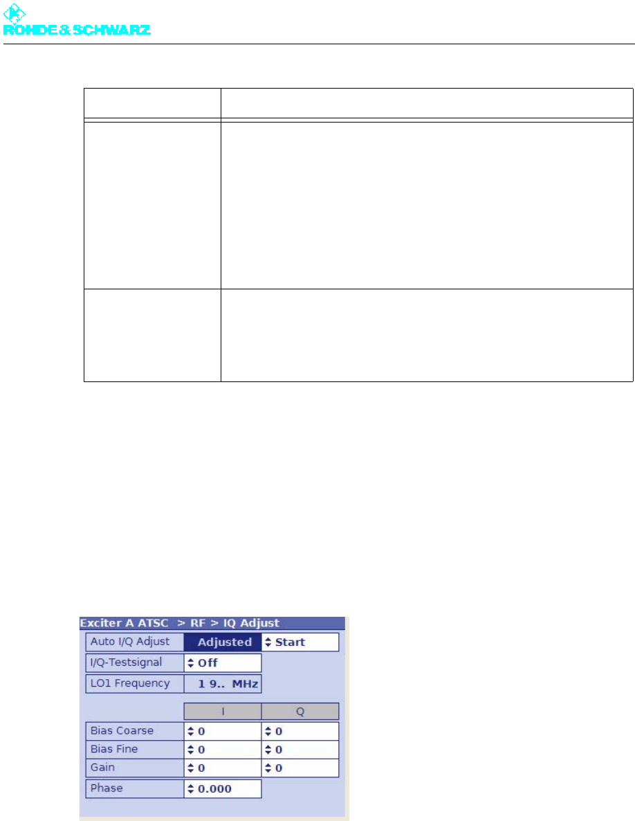
Chapter 4 Commissioning
2098.0188.72 - 4.16 - E-1
2.5.5 Adjusting the I/Q Modulator
When delivered from the factory, the I/Q modulator is preadjusted so that no customer in-
tervention is normally required.
If nonetheless an adjustment is necessary, proceed as follows:
1. Select Exciter A ATSC > RF > IQ Adjust.
The IQ Adjust window opens.
2. For automatic I/Q adjustment, select the item Start under Auto I/Q Adjust.
The automatic I/Q adjustment routine takes a few seconds. Running is displayed to in-
dicate that adjustment is in progress. After adjustment has been successfully performed,
Adjusted is displayed.
Note A guide to manual adjustment of the I/Q modulator can be found in the exciter manual.
Reference Selecting the reference source for stabilization of the frequency pro-
cessing (reference frequency source). The following settings are possi-
ble:
– Internal: Operation without external reference frequency source
– External 5 MHz: Operation with external 5 MHz reference
– External 10 MHz: Operation with external 10 MHz reference
– External 1pps: Operation with external time reference (1 pps)
The same setting options can be found in the RF > Reference menu
window.
OCXO Adjust Used to adjust an internal OCXO frequency (for operating mode "Inter-
nal")
The same setting options can be found in the RF > Reference menu
window.
Setting item Explanation
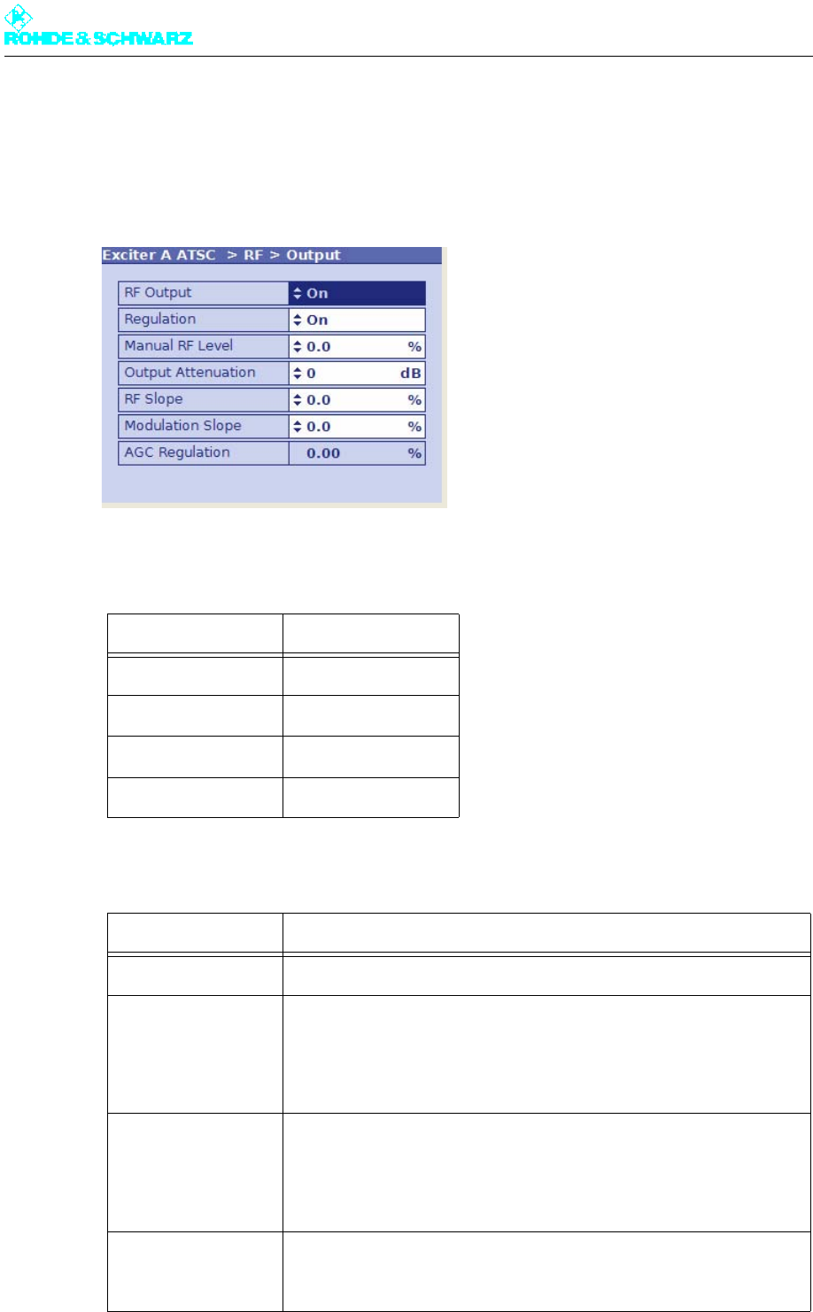
Chapter 4 Commissioning
2098.0188.72 - 4.17 - E-1
2.5.6 Setting RF Output
1. Select Exciter A ATSC > RF > Output.
The RF > Output window opens.
2. For normal transmission operation, enter the following settings:
The table below describes the adjustable parameters in detail:
Setting item Setting
Regulation ON
Output Attenuation 0 dB
RF Slope 0 %
Modulation Slope 0 %
Setting item Description
RF Output Enables (On) or disables (Off) the RF output.
Regulation Activates (On) or deactivates (Off) the output level control. During trans-
mission operation, control must be enabled.
The current status of the related level adjuster is displayed as a percent-
age under RF > RF Monitor > AGC Exciter.
Manual RF Level Manual setting of the output level; the setting has an effect only if output
level control is deactivated.
The current status of the related level adjuster is displayed as a percent-
age under RF > RF Monitor > AGC Exciter.
Output Attenuation For level adaptation purposes, an integrated attenuator with a value of
3 dB, 6 dB or 9 dB can be connected. This has no influence on the level
control.
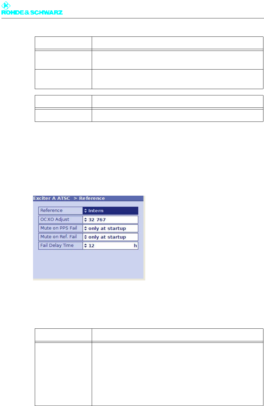
Chapter 4 Commissioning
2098.0188.72 - 4.18 - E-1
2.5.7 Specifying Behavior on Failure of a Reference Source
1. Select Exciter A ATSC > Reference.
The Reference window opens.
2. Select the required settings.
The table below describes the adjustable parameters in detail:
RF Slope Correction of a slope of the amplitude frequency response in the spec-
trum for equalizing subsequent components (output stage, filter).
Modulation Slope Correction of a curvature of the amplitude frequency response in the
spectrum for equalizing subsequent components (output stage, filter).
Display Description
AGC Regulation Displays the level of the output level control
Setting item Explanation
Reference Selects the reference frequency source. The following settings are pos-
sible:
– Internal: operation without external reference frequency source
– External 5 MHz: operation with external 5 MHz reference on
– External 10 MHz: Operation with an external 10 MHz reference
– External 1pps: Operation with an external time reference (1 pps)
The same setting options are available in menu window RF > Synthe-
sizer.
Setting item Description

Chapter 4 Commissioning
2098.0188.72 - 4.19 - E-1
2.6 Entering Output Stage Settings
2.6.1 Setting Up Output Stage
In the OS Setup and Rack Controller windows you can enter the basic settings for the out-
put stage.
Select Outputstage A > Setup > OS Setup.
The OS Setup window opens.
OCXO Adjust Setting for adjusting an internal OCXO frequency (for operating mode
"Internal")
The same setting options are available in menu window RF > Synthe-
sizer.
Mute on PPS Fail For setting the behavior in SFN mode in the event of failure of the exter-
nal time reference. The following settings are possible:
– off: The output signal is not suppressed.
– only at startup: the output signal is suppressed at startup until a valid
1 pps signal is recognized; if the 1 pps signal fails after successful
synchronization, the output signal is no longer suppressed.
– after fail delay time: The output signal is suppressed if the 1-pps sig-
nal fails for longer than the period specified at Fail Delay Time
This is the recommended setting for operation in SFN mode.
Mute on Ref. Fail For setting the behavior in SFN and MFN mode in the event of failure of
the external reference frequency source. The following settings are pos-
sible:
– off: The output signal is not suppressed.
– only at startup: the output signal is suppressed at startup until a valid
reference source is detected; if the reference source fails after a suc-
cessful synchronization, the output signal is no longer suppressed
– after fail delay time: The output signal is suppressed if the reference
source fails for longer than the period specified at Fail Delay Time
This is the recommended setting for operation in SFN mode.
Fail Delay Time If a reference source fails, it takes the time given here before the output
signal is suppressed. The setting is only effective if the behavior after fail
delay time is set under Mute on PPS Fail or Mute on Ref. Fail.
Selection: 0 to 24 hours; 0 hours = no delay time
Setting item Explanation
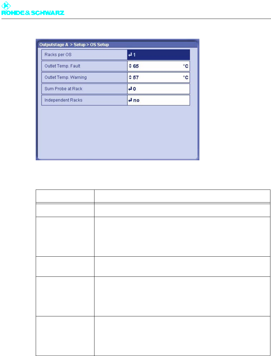
Chapter 4 Commissioning
2098.0188.72 - 4.20 - E-1
The table below explains the user-selectable parameters in detail:
Select Outputstage A/B > Setup > Rack Setup > Rack 1 > Rack Controller.
The Rack Controller window opens.
Setting Explanation
Racks per OS Number of racks belonging to the output stage
Outlet Temp. Fault Switch-off threshold with overtemperature
If this threshold is exceeded, the rack controller shuts down the transmit-
ter rack.
Value: 45 °C to 65 °C
Nominal value: 65 °C
Outlet Temp. Warning Warning threshold for overtemperature
A warning is generated if this threshold value is exceeded.
Sum Probe at Rack Used to select the transmitter rack (rack controller) to which the test
points for forward/reflected power of the entire output stage are con-
nected
Only with active and passive output-stage standby
Independent Racks Possibility of dividing the output stage logically into independent racks
– no: All racks of the output stage are controlled together and all act on
the same RF output (default setting).
– yes: The racks of the output stage can have separate RF outputs and
can be controlled individually (e.g. ON/OFF command).
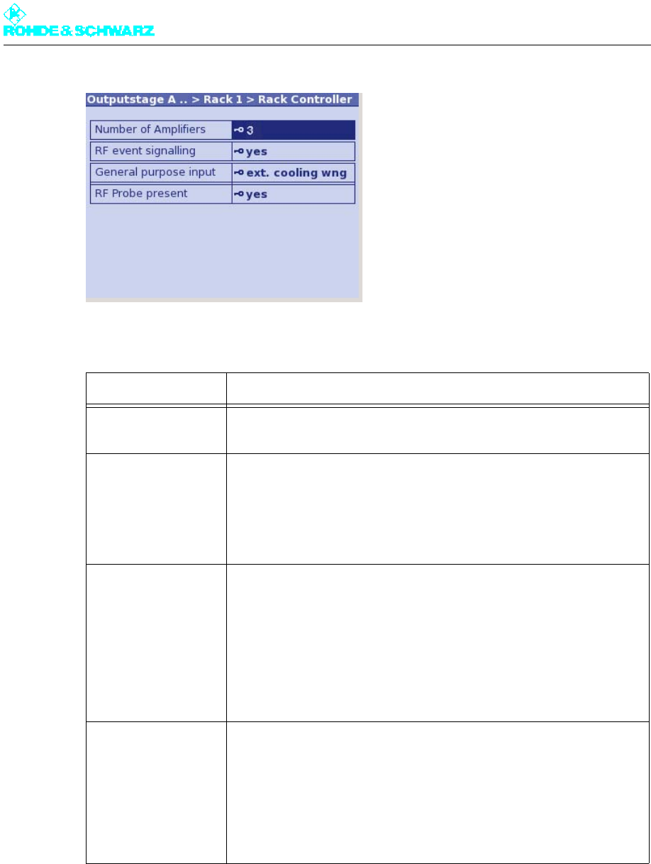
Chapter 4 Commissioning
2098.0188.72 - 4.21 - E-1
The table below shows all the user-selectable parameters:
2.7 Setting Transmitter Output Power
1. Connect a power meter to the free test point P14C on the forward power system AVG.
2. Select Outputstage A > Output Power.
The Output Power window opens.
Setting Explanation
Number of Amplifiers Used to enter the number of amplifiers installed in the rack
Value: 1 to 4
RF event signaling – yes: If the minimum or maximum limits for forward and reflected
power (RF Fail Limit, RF Warning Limit) are violated at the test points
of the rack, warnings or fault messages are output (default setting).
– no: Output of RF warnings and fault messages at the test points of the
rack is suppressed.
General purpose
input
Assignment of a free line on the rack controller for customer-specific
purposes:
– unused: Line is not used.
– door open: Line is reserved for indicating when door contacts are
open.
– ext. cooling wng: Line is reserved for warnings from an external cool-
ing system.
– ext. cooling flt: Line is reserved for fault messages from an external
cooling system.
RFProbe present – yes: A measurement system is connected to the rack controller of the
rack.
Only with active or passive output-stage standby if the measurement
system is connected to this rack.
– no: No measurement system is connected to the rack controller of the
rack.
Correct setting in all other cases.
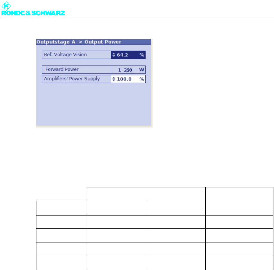
Chapter 4 Commissioning
2098.0188.72 - 4.22 - E-1
3. Keep changing the value at Reference Voltage Vision until the desired transmitter pow-
er is measured on the power meter (the table "Transmitter power and coupling attenua-
tion at P14C" specifies the benchmark figures).
4. Remove the power meter from the test point P14C.
Tab. 1 Transmitter power and coupling attenuation at P14C
2.8 Calibrating Power Displays
Note The coupling attenuation and display matching of test points have been factory calibrated.
2.8.1 Calibrating Forward and Reflected Power Displays
Forward power display
Note To allow calibration, the transmitter must be operated at the required transmitter power.
1. Select NetCCU > RF Probe Antenna > RF Probe Forward.
The RF Probe Forward window opens.
Transmitter power Coupling attenuation at
test point P14C
Transmitter type MER 34 dB MER 33 dB a)
a) The specified output power cannot be achieved on every channel. Only n x 450 W ATSC power is possible
up to 486 MHz.
R&S NV8301 430 W 500 W 52 dB
R&S NV8302 860 W 1000 W 55 dB
R&S NV8303 1290 W 1500 W 57 dB
R&S NV8304 1720 W 1800 W b)
b) The output power is limited by the maximum power-handling capacity of the harmonics filter.
58 dB
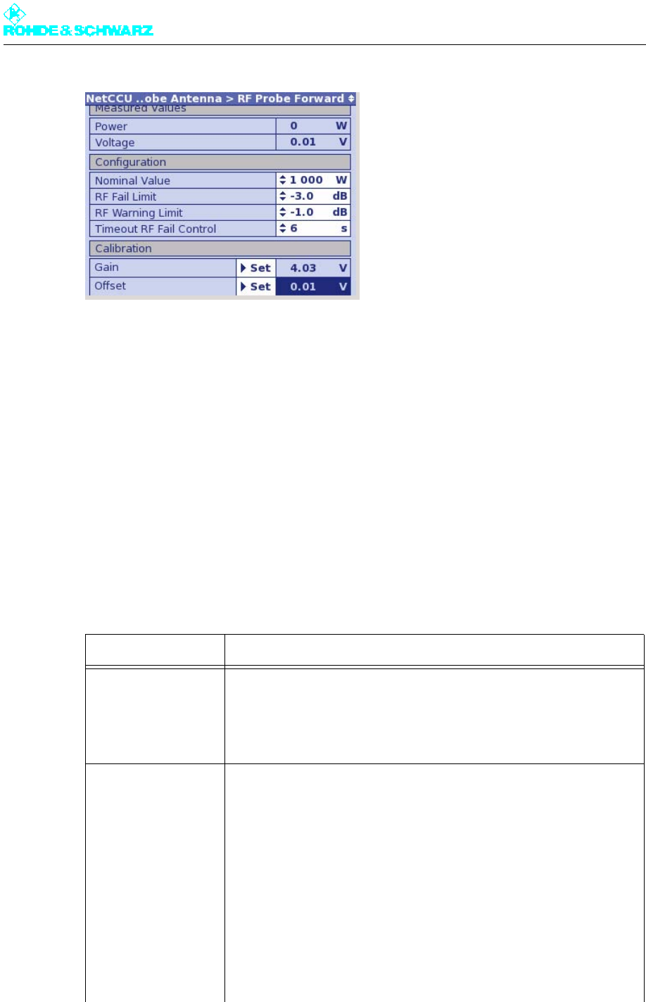
Chapter 4 Commissioning
2098.0188.72 - 4.23 - E-1
2. Under Nominal Value, enter the required transmitter power that you set in the previous
section.
3. Use Set Gain to measure and save the DC voltage of the forward-power test point at
nominal output power.
Note To abort, exit the Trigger: Set info window by pressing Back. To continue, confirm by
pressing OK.
4. Switch off the transmitter.
5. Use Set Offset to measure and save the DC voltage of the forward-power test point at
0 W output power.
Note To abort, exit the Trigger: Set info window by pressing Back. To continue, confirm by
pressing OK.
6. Enter the other settings as shown in the table below:
Function Explanation
Measured Values Measurement display
Power Current forward power
Voltage Currently measured DC voltage of the test point
Configuration Definition and setting of a nominal value for forward power. Setting of
upper and lower thresholds for forward power; warnings and fault mes-
sages are issued if these thresholds are violated.
Nominal Value Used to enter the nominal value, determined if necessary by external
measurement of the forward power
RF Fail Limit Used to select a dB value referenced to the set nominal power for for-
ward power; a fault message is issued if the actual value drops below
the nominal value.
RF Warning Limit Used to select a dB value referenced to the set nominal power for for-
ward power; a warning is issued if the actual value drops below the
nominal value
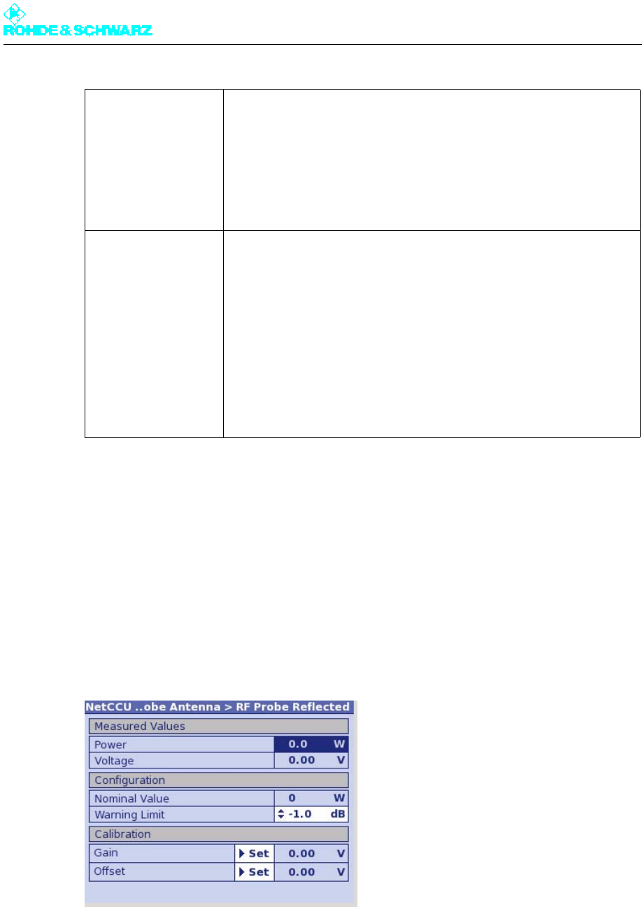
Chapter 4 Commissioning
2098.0188.72 - 4.24 - E-1
Verification of the calibration
Calibration of the power indication was successful if the values displayed in the Calibration
window area for Gain and Offset are not equal to zero.
Reflected power display
Note To allow calibration, the transmitter must be operated at the required transmitter power.
1. Select NetCCU > RF Probe Antenna > RF Probe Reflected.
The RF Probe Reflected window opens.
2. Use Set Gain to measure and save the DC voltage of the reflected-power test point at
nominal output power.
Note To abort, exit the Trigger: Set info window by pressing Back. To continue, confirm by
pressing OK.
3. Switch off the transmitter.
Timeout RF Fail Con-
trol
Used to select the time that the lower threshold for the forward power
(specified as the RF Fail Limit) must be violated for before a fault mes-
sage is output. For example, if a value of 3 dB has been entered as the
RF Fail Limit and the actual value drops below that level for 8 seconds
(typical setting for Timeout for RF Fail Control), a fault message will be
output.
Calibration Execution of calibration and display of the results.
Gain Internal measurement value of the nominal value
Offset Deviation from the zero value of the power display
Set Gain Used to calibrate the internal measurement system. Set Gain assigns
the currently measured DC voltage to the nominal value for transmitter
power.
Set Offset Used to calibrate the zero point as of which the externally measured
power is displayed. Set Offset calibrates the zero point.
Function Explanation
Chapter 4 Commissioning
2098.0188.72 - 4.25 - E-1
4. Use the Set Offset command to measure and save the DC voltage of the reflected-pow-
er test point at 0 W output power.
Note To abort, exit the Trigger: Set info window by pressing Back. To continue, confirm by
pressing OK.
5. Enter the other settings as shown in the table below:
Verification of the calibration
Calibration of the power indication was successful if the values displayed in the Calibration
window area for Gain and Offset are not equal to zero.
Function Explanation
Measured Values Measurement display
Power Current reflected power
Voltage Currently measured DC voltage of the test point
Configuration Setting of a warning threshold for the reflected power
Nominal Value Forward power/50 (corresponds to the maximum reflected power)
Warning Limit Used to select a dB value for the warning threshold referenced to the
reflection switch-off threshold which is at a return loss of -17 dB (corre-
sponding to a reflected power/forward power ratio of 1/50)
Calibration Execution of calibration and display of the results
Gain Internal measurement value of the nominal value
Offset Deviation from the zero value of the power display
Set Gain Used to calibrate the internal measurement system. Set Gain stores the
internal measurement value for the entered (measured) nominal value.
Set Offset Used to calibrate the zero point as of which the externally measured
power is displayed. Set Offset calibrates the zero point.
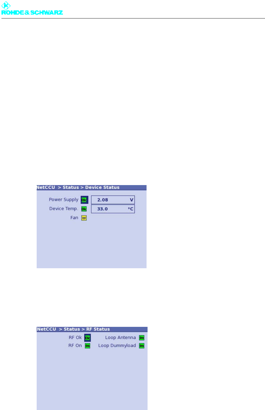
Chapter 4 Commissioning
2098.0188.72 - 4.26 - E-1
3 Completion of Startup Procedure
When the steps described in the above sections have been carried out, the transmitter is
ready for operation. Each transmitter receives a test report from the final testing department
complete with measurement data on every quality parameter. This means that on site com-
pliance testing is only necessary at the customer's request.
3.1 Final Steps
3.1.1 Checking R&S NETCCU800 Status Display
1. Select NetCCU > Status > Device Status.
The Device Status window opens.
2. Check the status of the warning and fault indicators.
If a transmitter is ready to operate, no warnings or faults will be signaled.
3. Select NetCCU > Status > RF Status.
The RF Status window opens.
4. Check the status of the warning and fault indicators.
If a transmitter is ready to operate, no warnings or faults will be signaled.
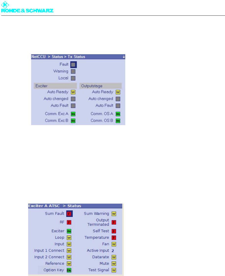
Chapter 4 Commissioning
2098.0188.72 - 4.27 - E-1
5. Select NetCCU > Status > Tx Status.
The Tx Status window opens.
6. Check the status of the warning and fault indicators.
If a transmitter is ready to operate, no warnings or faults will be signaled.
3.1.2 Checking Exciter Status Display
1. Select Exciter A/B ATSC > Status.
The Status window opens.
2. Check the status of the warning and error indicators.
If a transmitter is ready to operate, no warnings or errors will be signaled.
3.1.3 Checking Output Stage Status Display
1. Select Outputstage > Status > OS Status.
The OS Status window opens.
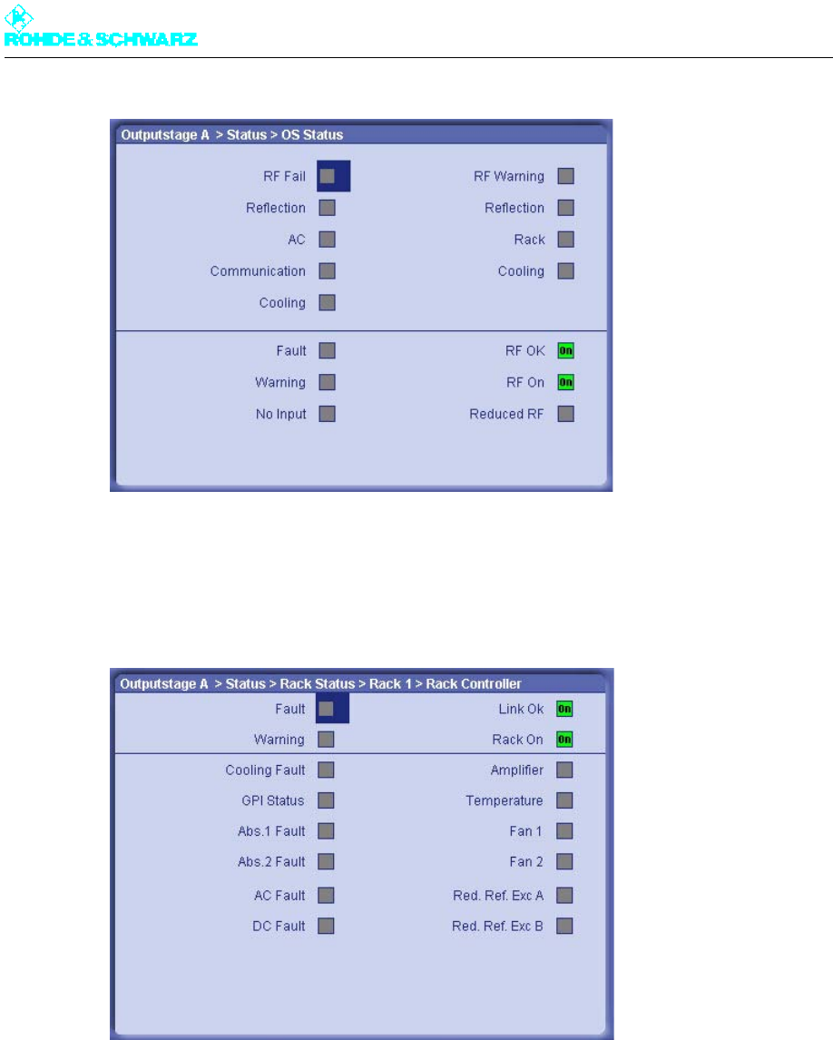
Chapter 4 Commissioning
2098.0188.72 - 4.28 - E-1
2. Check the status of the warning and fault indicators.
If a transmitter is ready to operate, no warnings or faults will be signaled.
3. Select Outputstage > Status > Rack Status > Rack x > Rack Controller.
The Rack Status > Rack x > Rack Controller window opens.
4. Select Outputstage > Status > Rack Status > Rack x > Amplifier.
The Rack Status > Rack x > Amplifier window opens.
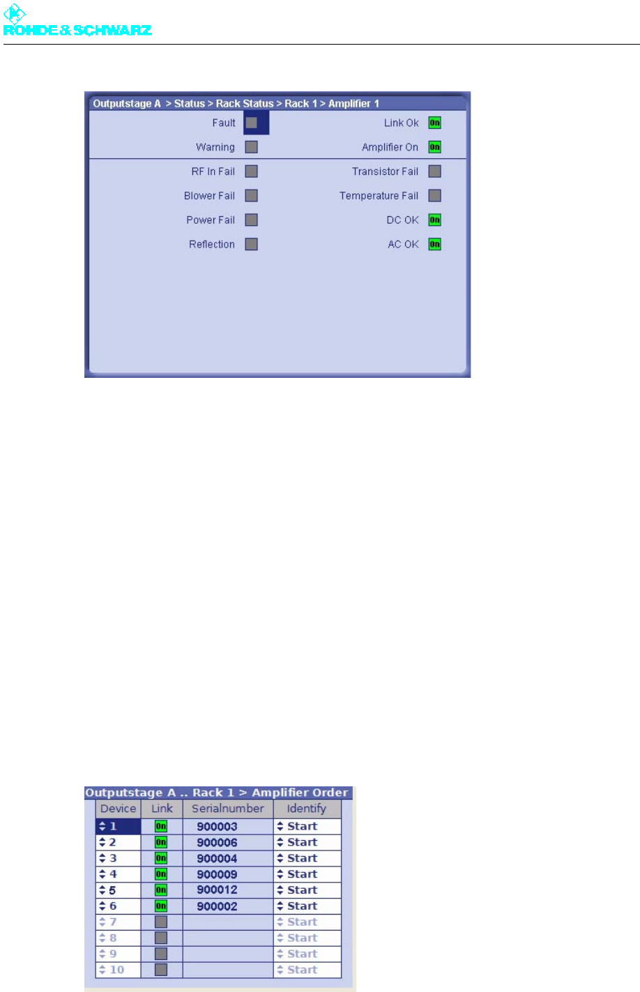
Chapter 4 Commissioning
2098.0188.72 - 4.29 - E-1
5. Check the status of the warning and fault indicators.
If a transmitter is ready to operate, no warnings or faults will be signaled.
3.2 Adjusting Amplifier Order Numbers to Installation
Positions in Rack
After the transmitter system has been put into operation, entries for the amplifiers (of a par-
ticular rack) are displayed in the menu path for the output stage with consecutive numbering
(Amplifier 1 to max. Amplifier 10). Since the numbering is derived from the chronological
sequence in which the amplifiers can be detected on the CAN bus, it does not always cor-
respond to the sequence in which the amplifiers are physically arranged from top (= 1) to
bottom (= n) in the rack.
To make association between menu and amplifier easier, the entries can be sorted.
1. Select Outputstage A > Setup > Rack Setup > Rack 1 > Amplifier Order.
The Amplifier Order window opens.

Chapter 4 Commissioning
2098.0188.72 - 4.30 - E-1
2. In the Identify column, activate the function Start (starting with Device No. 1).
The LEDs on the associated amplifier flash. This identifies the amplifier with the (tem-
porary) order number 1.
3. Under Device, change the order number according to the position of the identified am-
plifier in the rack.
4. Repeat steps 2 to 3 for the other amplifiers in the rack.
The procedure is completed when each order number in the Device column correctly
corresponds to the position of the associated amplifier in the rack.
3.3 Clearing Event Memory
There are four event memories for each of the R&S NetCCU800, exciter and OS (output
stage) modules.
Summary
Status
Warning
Fault
These event memories need to be cleared for all the modules before the transmitter begins
regular transmission.
1. Select NetCCU > Logbook > Status.
The Status window opens.
2. Select the Clear Logbook command in the context menu.
The entries are cleared.
3. Repeat the procedure for each of the event memories listed.

Chapter 4 Commissioning
2098.0188.72 - 4.31 - E-1
4 Precorrection
This section describes the non-linear precorrection sequence in manual mode.
4.1 Functions of Nonlinear Precorrector
4.1.1 General
In the basic version, the graphical user interface of the non-linear precorrector for DTV and
video signals consists of the Nonlinear control panel and the FreqCorrection control pan-
el. In the case of ATV split, two further control panels are provided: Dynamic Control for
the video precorrector and Nonlinear Audio for the audio signal. In combined mode an au-
dio phase precorrector is also provided for audio.
4.1.2 Linear Basic Precorrection
The basic functions of the non-linear precorrector can be accessed via the Nonlinear and
Nonlinear Audio control panels. Additional functions can be performed in the other control
panels.
Every non-linear precorrector consists of an amplitude precorrector and a phase precorrec-
tor, each independently affecting the phase distortion and amplitude distortion of the same
signal. The setting of the characteristic is displayed in a graphic in which the X axis repre-
sents the instantaneous signal amplitude. The figures 0% and 100% stand for no signal am-
plitude and maximum amplitude respectively. The Y axis represent the effect and is scaled
to ±50 % for amplitude precorrection and ±45° for phase precorrection. 50% means that at
100% amplitude the level is increased by 3 dB.
Every precorrector has a series of frequency reference points which are used to model the
characteristic. Frequency reference points can be user-defined, shifted in the X and Y di-
rections, be given a fixed or free slope and be deleted. In the X direction a frequency refer-
ence point can only be shifted between the two adjacent reference points. The connections
between frequency reference points are computed by means of spline functions.
Every characteristic consists of at least two points, one of which must be at 0% and the oth-
er at 100%.
In the case of amplitude precorrection the first point is at [0%, 0%] and cannot be shifted.
The second point is at 100% and can be shifted without restriction in the Y direction. A rising
or falling straight line between the two points represents only an amplification or attenuation
of the signal and does not create non-linear products.
In the case of phase precorrection the first point is at 0% and the second point is at 100%.
Both points can be shifted without restriction in the Y direction. A straight line parallel to the
amplitude axis creates only a signal phase shift and does not create non-linear products.

Chapter 4 Commissioning
2098.0188.72 - 4.32 - E-1
4.1.3 Nonlinear Frequency Responses
As an additional function, the non-linear components of the DTV/video precorrection (am-
plitude or phase precorrection) can be assigned a frequency response in the FreqCorrec-
tion control panel, and the effect of the frequency response depends on the modulation.
If the amplitude precorrection or phase precorrection is affected by an amplitude frequency
response, only the "individual" precorrection is affected. Amplitude precorrection and phase
precorrection have no influence on one another.
If the amplitude precorrection or phase precorrection is affected by a phase frequency re-
sponse, part of the "individual" precorrection affects the other precorrection. The amplitude
precorrection and phase precorrection therefore have an influence on one another.
4.1.4 Dynamic Precorrection (ATV Split Only)
In ATV split systems, the large fluctuations in the average value of the video signal brings
about temperature changes in the output-stage transistor which lead to changes in the out-
put stage characteristic as a function of the average value of the modulation. This error can
be compensated for by dynamically modifying the characteristic as a function of the aver-
age signal value.
4.1.5 Audio Phase Precorrection (ATV Combined Only)
In ATV combined systems, the common amplification of video and audio causes the audio
signal to be affected by the video signal. This effect can be minimized with the aid of an
audio phase precorrector.
4.2 General Information on Operating Precorrector
The precorrector is operated by means of a web browser. The R&S NetCCU800 or exciter
provides a JAVA applet which is launched by the web browser. This applet contains all of
the elements needed to operate the precorrector.
Note Detailed information on operating the precorrector and configuring the graphical user inter-
face can be found in the chapter "Operation" of the exciter manual.
4.3 Performing Precorrection
The objective of precorrection is for the precorrector to simulate the non-linear characteris-
tic of the amplifier as accurately as possible in order to increase the linearity of the output
signal.
However, the precorrection limit is tied to the overload capacity of the output stage. To ob-
tain the greatest possible efficiency and lowest possible costs for a given transmitter, the
output stages are set so as to achieve a transmitter output signal of the required quality.

Chapter 4 Commissioning
2098.0188.72 - 4.33 - E-1
4.3.1 General Requirements
The following requirements should be fulfilled prior to precorrection:
The transmitter must be operated at its nominal power output and the system level must
be adjusted at all points.
Precorrection must be on, for which the Nonlinear control panel must be selected in the
precorrector graphical interface. A precorrection curve consisting of a straight line posi-
tioned on the X axis must be set for the amplitude precorrection and another for the
phase precorrection.
4.3.2 Determining System Levels
The graphical area contains lines representing distinctive signal levels such as all-white lev-
el (Wht), all-black level (Blk) and sync pulse level (Sync), as well as sync pulse level (Sync/
Aud) in the case of ATV combined. In DVT the level lines indicate the peak level (Peak) and
the average value (Avh). These marks indicate maximum level; the actual level may be dif-
ferent.
Changes to the set curve that affect only the range above the system level have no effect
on the signal or on precorrection of the signal.
The following method can be used to determine the actual values:
1. Use two interpolation points to determine the ends of the effective dynamic range in or-
der to define the possible setting range of the precorrector:
a) Add two interpolation points to the amplitude precorrection graph in the area above
the highest mark and set their slope.
You now have four points, consecutively numbered 1 to 4 from left to right. Points 2
and 3 are each indicated by an arrow.
b) Shift points 3 and 4 in the positive Y direction by +50%. Point 3 should then be im-
mediately adjacent to point 2.
c) Use the Write button to write this curve to the precorrector.
2. Now use the Navigator window to reduce the position of interpolation points 2 and 3 to-
gether in steps of one percent. Observe the effect:
3. Restore the original status.
ATV Split In ATV split systems, the first effect is seen in the sync pulse length, which
can be clearly observed on the TV demodulator (sync pulse length dis-
play) or the TV analyzer.
ATV Combined In ATV combined systems, the first effect is seen in the intermodulation
products about the two sound carriers fTx ± default f(T2-T1)
DTV In DTV systems the effect is seen as a reduced shoulder distance
The upper of the two interpolation points thus represents the determined dynamic range limit.
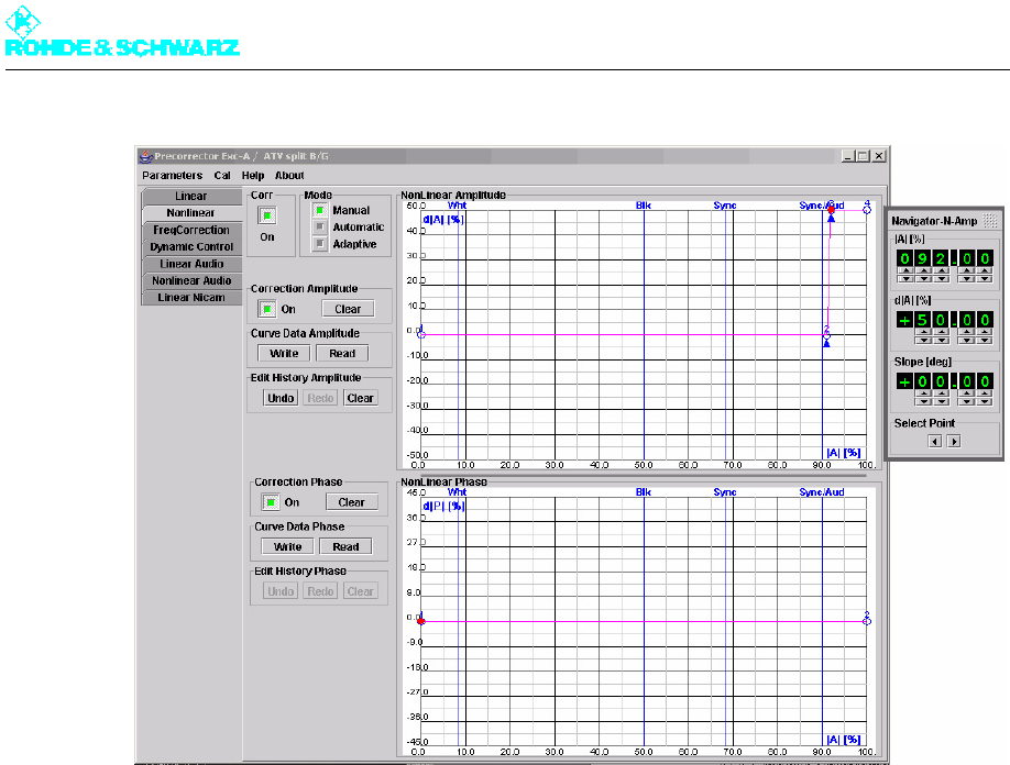
Chapter 4 Commissioning
2098.0188.72 - 4.34 - E-1
Fig. 1 Determining system levels
4.3.3 Precorrection Procedure
4.3.3.1 Starting Precorrection
Requirements
The following requirements should be fulfilled prior to precorrection:
The transmitter must be operated at its nominal power output and the system level must
be adjusted at all points.
A spectrum analyzer must be connected to the transmitter output.
Note A measurement should be taken upstream of the output filter as the shoulders are difficult
to detect owing to the band limiting of the filter. When measuring signals using the spectrum
analyzer, it is important to ensure that the precorrection target (e.g. 38 dB shoulder dis-
tance) is well above the noise limit, but the frequency range of the spectrum analyzer is
such that no intermodulation is generated in its input section.
Precorrection must be activated. In the graphics area for the amplitude and phase pre-
correction, two interpolation points are present in each graph: the first point is modula-
tion 0% with magnitude 0% or 0°, and the second point is modulation 100% with
magnitude 0% or 0°.
A DTV spectrum with clear shoulders should be visible on the analyzer.

Chapter 4 Commissioning
2098.0188.72 - 4.35 - E-1
Fig. 2 Example: DVB signal spectrum
1) Shoulder distance
2) Useful signal
3) Shoulder
Start
1. Start precorrection with the phase precorrection.
2. Since phase precorrection and amplitude precorrection affect one another, repeat both
precorrection procedures if necessary until the optimum result is obtained.
4.3.3.2 Phase Precorrection
Proceed as follows for phase precorrection:
1. Add in a phase reference point at about 10%.
This position corresponds to a lower modulation of the amplifier.
2. Shift the magnitude of the interpolation point for 100% up or down in steps of 0.5 or
smaller (+ or -) until the shoulder distance on the analyzer visibly improves.
3. Keep improving the shoulder distance on the analyzer until the optimum result is ob-
tained.
4. Set another point at about 35%.
5. Shift the magnitude of the interpolation point for 10% up or down in steps of ±0.5 or
smaller until the shoulder distance on the analyzer visibly improves.
6. Keep shifting the magnitudes of interpolation points 2 (10%), 3 (35%) and 4 (100%) in
small steps until the optimum result is obtained.
Note Further interpolation points can be added for an optimum precorrection. The recommended
number is four to a maximum of six interpolation points (including the interpolation points at
0% and 100%).
If phase precorrection gives no improvement or only a minor one, the phase precorrection
must be canceled and amplitude precorrection must be carried out first.
1
2
3 3
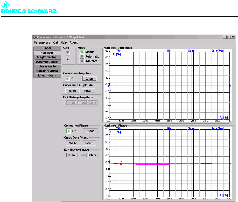
Chapter 4 Commissioning
2098.0188.72 - 4.36 - E-1
Fig. 3 Typical curve for starting precorrection with amplitude precorrection switched off
4.3.3.3 Amplitude Precorrection
The procedure for amplitude precorrection is the same as that for phase precorrection.
If the first interpolation point brings about an improvement, deal similarly with the other in-
terpolation points.
1. Set the interpolation points more or less at the positions of the phase values.
2. Set all magnitudes to zero.
3. Starting with the interpolation point for the white level (low), change the magnitude (in
steps of ± 0.5 or smaller) in order to find the precorrection.
Note From here on it is a prerequisite that the precorrection for phase and amplitude has been
optimized at all interpolation points.
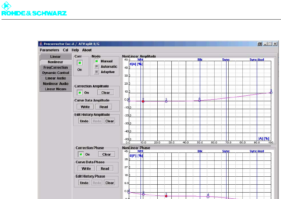
Chapter 4 Commissioning
2098.0188.72 - 4.37 - E-1
Fig. 4 Typical curve with both phase and amplitude precorrection switched on
4. Optimize the shoulder distance using all interpolation points again, in particular by shift-
ing the interpolation point at 100%.
Keep carrying out phase precorrection and amplitude precorrection alternately until no fur-
ther improvement can be obtained.
Note Further interpolation points can be added for an optimum precorrection. The recommended
number is four to a maximum of six interpolation points (including the interpolation points at
0% and 100%).
4.3.3.4 Frequency-Dependent Precorrection
Background
The FreqCorrection control panel can be used to influence the characteristic by means of
an amplitude and/or phase frequency response, the effect of which is dependent on the lev-
el.
A set frequency response is applied to all signal components having a level greater than
the selected threshold. On the other hand lesser signal components are unaffected.
An amplitude frequency response (Amplitude Slope Amplitude 1/2 or Amplitude Slope
Phase 1/2) and a phase frequency response (Phase Slope Amplitude 1/2 or Phase Slope
Phase 1/2) can be applied to the amplitude characteristic and the phase characteristic in-
dependently of one another. Two independent thresholds are available (Position Point 1
or Position Point 2). The position of the thresholds (1 or 2) and their effect (A or P) are
symbolically represented in the graphic.
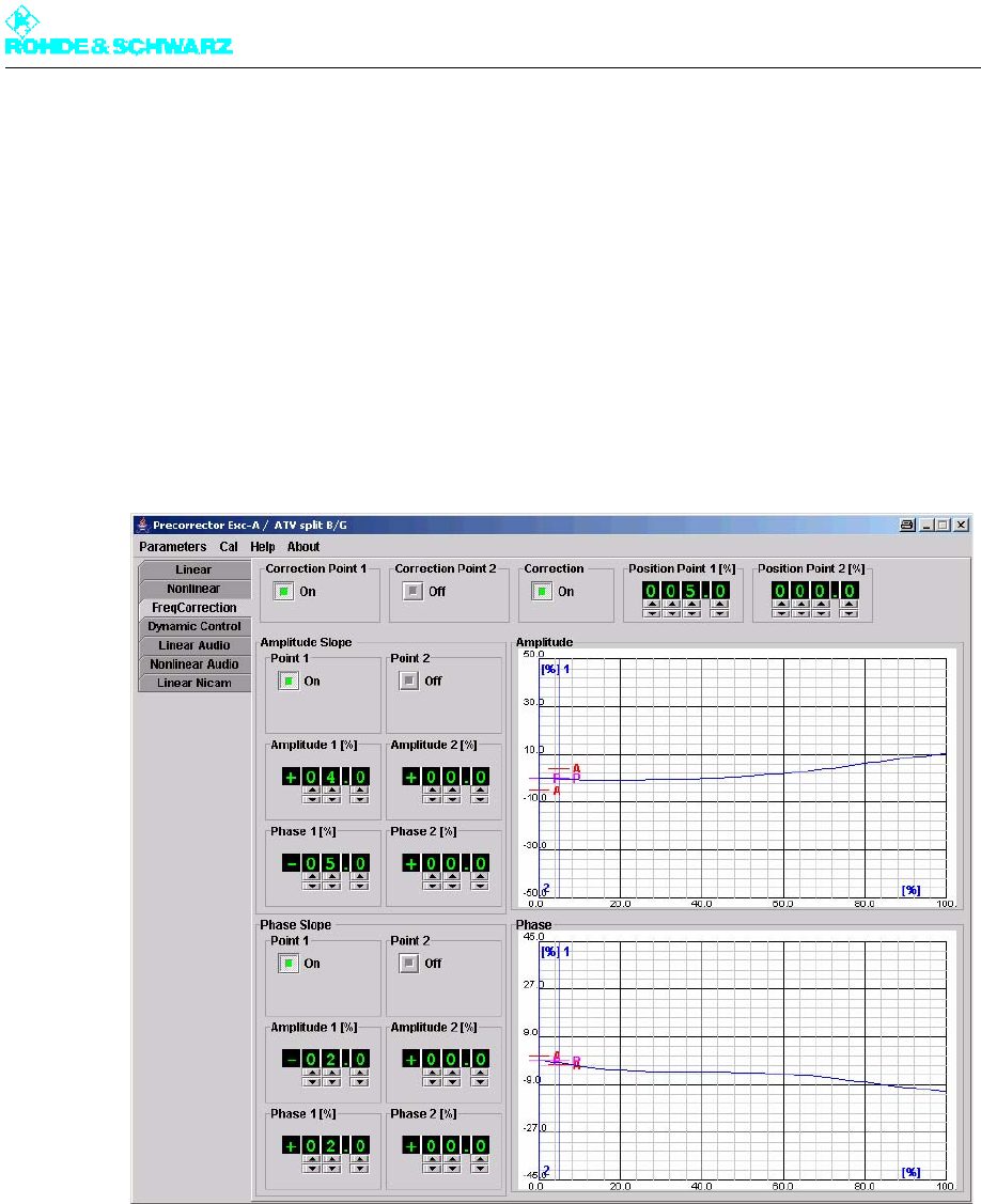
Chapter 4 Commissioning
2098.0188.72 - 4.38 - E-1
Optimizing the shoulder distance
1. First use the the Curve Data Amplitude Read and Curve Data Phase Read buttons in
the Nonlinear control panel to read off the characteristics currently set in the precorrec-
tor.
The characteristics are displayed in the display part of the graphic.
2. Go to the FreqCorrection control panel.
The characteristics can be seen in the graphic.
3. In the precorrector graphical user interface, switch Correction to ON and also activate
Correction Point 1, Amplitude Slope Point 1 and Phase Slope Point 1. Set Position
Point 1 to 5%.
Fig. 5 The FreqCorrection user interface with an onset point at 5%
4. Now minimize the shoulder distance to left and right of the signal range by alternately
setting the amplitude and phase regulators with the aid of the slopes of point 1.
5. Go back to the Nonlinear control panel.
6. If necessary optimize the characteristic.
7. Keep repeating steps 2, 3, 4 and 6 until the shoulder distance to left and right of the sig-
nal range reaches the required value between 37 dB and 40 dB.
If necessary you must to some extent suppress the frequency dependent non-linearity in
the upper level range.
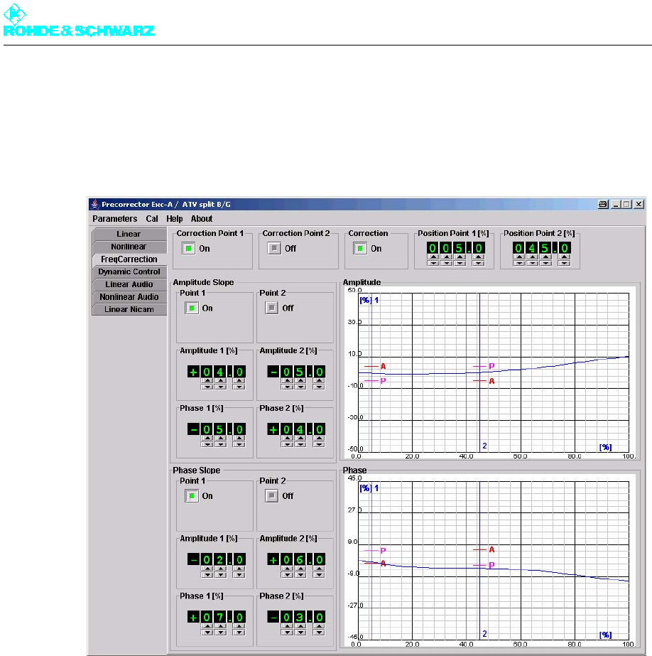
Chapter 4 Commissioning
2098.0188.72 - 4.39 - E-1
1. Set another onset point in the upper level range >25%.
2. Optimize the shoulder distance by alternately setting the amplitude and phase regula-
tors with the aid of the slopes of point 2.
The slopes will then point in the opposite direction than at Point 1.
Fig. 6 The FreqCorrection user interface with a second onset point
4.3.3.5 Fine Adjustment Using an Existing or Preset Characteristic
If the required data is not or is no longer observed to be in an existing or factory-set precor-
rection characteristic, the precorrection does not necessarily have to be readjusted.
An adjustment to the true amplifier characteristic can be obtained by changing individual
interpolation points. The range with the greatest effect can be determined by slightly chang-
ing individual interpolation points. Changing the interpolation values in this range will most
probably produce the desired result. Changes should be made in small steps, preferably
with the aid of the Navigator window. A change must be undone if it does not result in an
improvement.

Chapter 4 Commissioning
2098.0188.72 - 4.40 - E-1