Rohde and Schwarz TMU925 UHF DTV ATSC 1KW TO 2.5 KW TRANSMITTER FAMILY User Manual Part 1
Rohde & Schwarz Inc UHF DTV ATSC 1KW TO 2.5 KW TRANSMITTER FAMILY Part 1
UserManual.wiki
>
Rohde and Schwarz
>
TMU925 User Manual
>
User Manual Part 1
Contents
1.
User Manual Part 1
2.
User Manual Part 2
User Manual Part 1
Navigation menu
Upload a User Manual
Namespaces
Wiki Guide
HTML
PDF
Info
Views
User Manual
Discussion / Help
Navigation


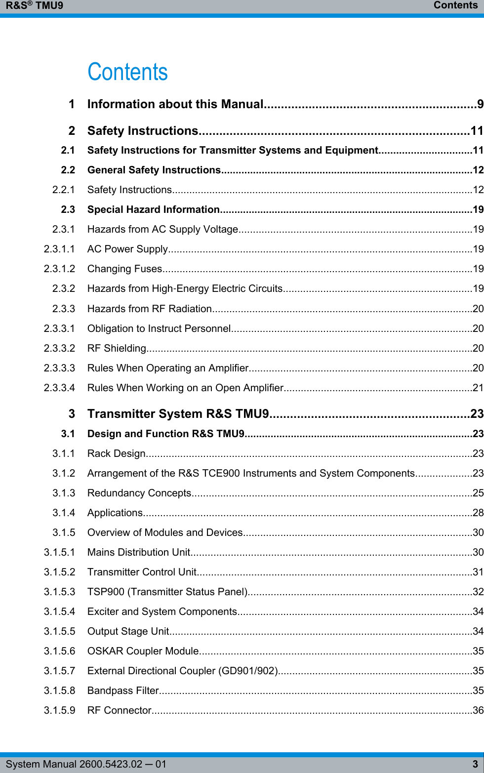
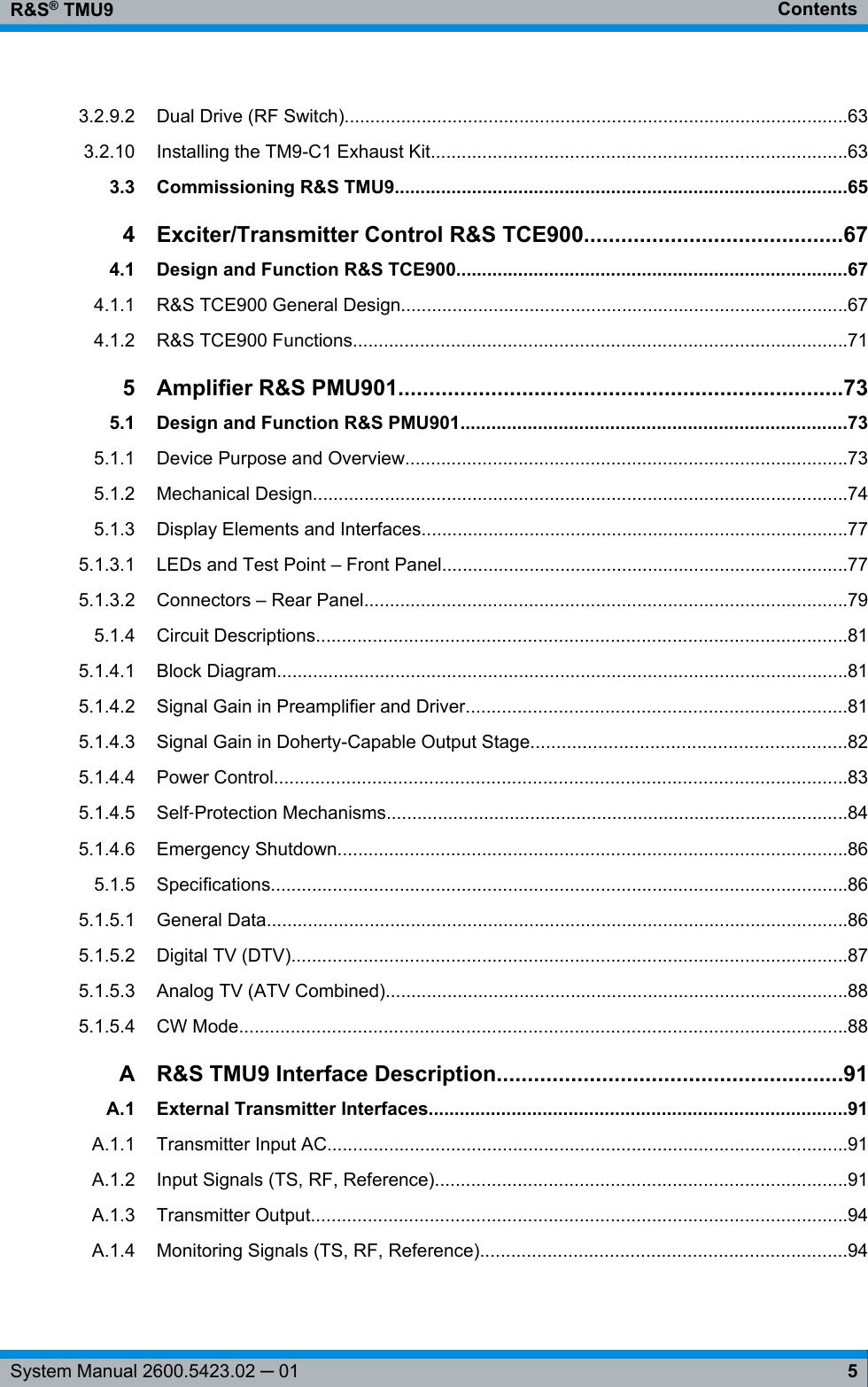


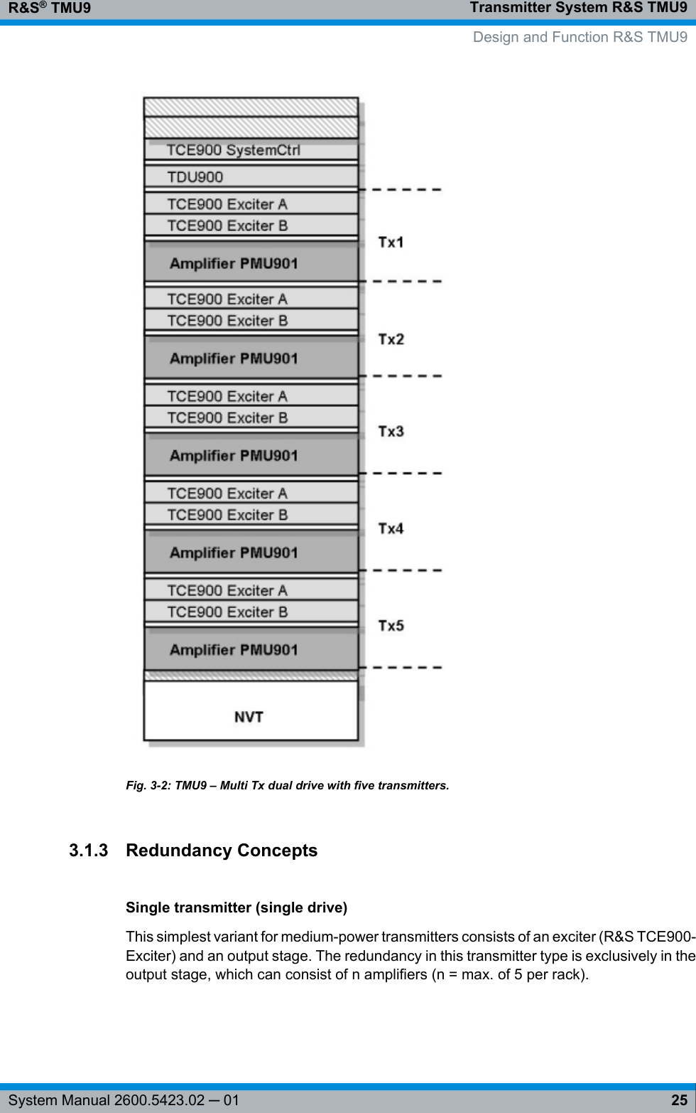
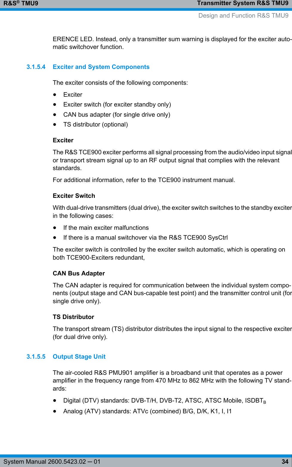
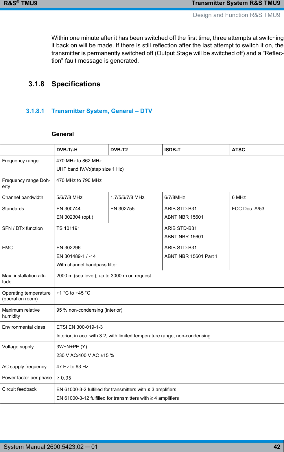
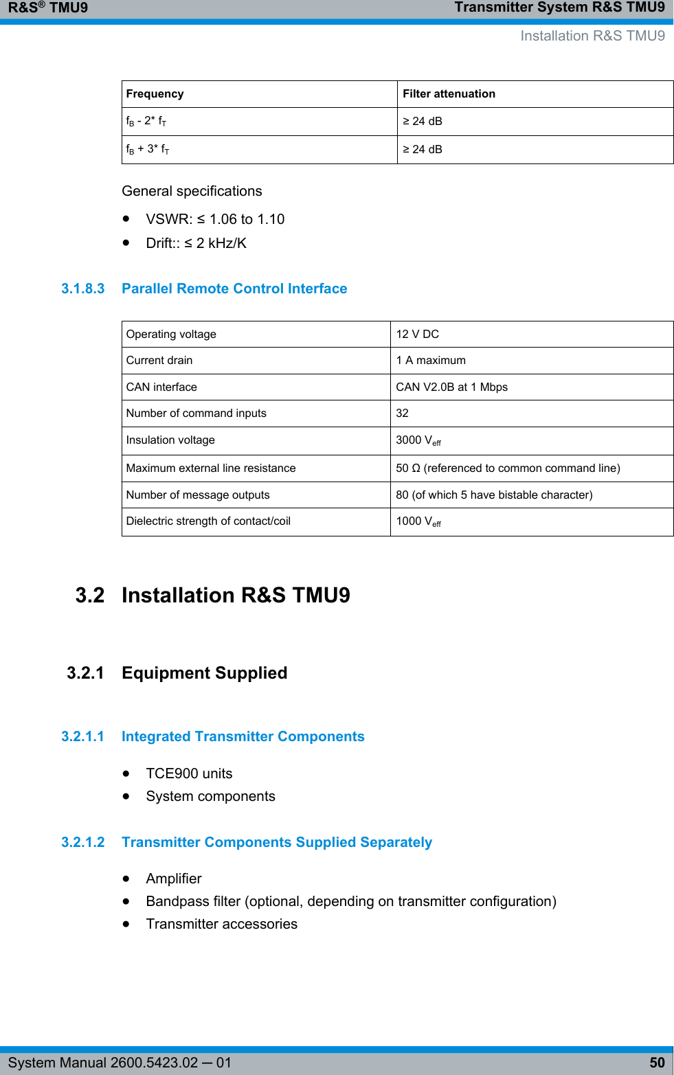
![Transmitter System R&S TMU9R&S® TMU932System Manual 2600.5423.02 ─ 01The current status of the transmitter system can optionally be shown on a straightforwardcolor display via the R&S TDU900.3.1.5.3 TSP900 (Transmitter Status Panel)The TSP900 allows local operation of a transmitter. One TSP900 is allocated to eachtransmitter (single drive, dual drive, backup drive) and is fastened to the front panel ofthe respective transmitter.Fig. 3-9: TSP900 (Transmitter Status Panel)For single drive, dual drive, and backup drive transmitters with optional TDU900, theTSP900 (keys and LEDs) are active in parallel with the TDU900.For N+1 and MultiTx transmitters, each individual transmitter has a separate TSP900,which enables local operation of the single transmitter.Meaning of the LEDs Single drive Backup drive Dual drive OK (green) Transmitter allOKTransmitter allOKTransmitter all OKWarning (orange) Warning for trans-mitterWarning fortransmitterWarning for trans-mitterFault (red) Fault for transmit-terFault for transmit-terFault for transmit-ter Input OK Sum input statusof the exciter isOKSum input statusof the activeexciter is OK [2]Sum input statusof the activeexciter is OK [2]W Sum input statusof the exciter hasa WarningSum input statusof the activeexciter has aWarning [2]Sum input statusof the activeexciter has aWarning [2]F Sum input statusof the exciter hasa FailSum input statusof the activeexciter has a Fail[2]Sum input statusof the activeexciter has a Fail[2] Design and Function R&S TMU9](https://usermanual.wiki/Rohde-and-Schwarz/TMU925.User-Manual-Part-1/User-Guide-2289399-Page-40.png)
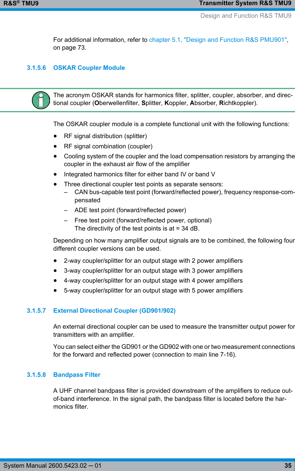
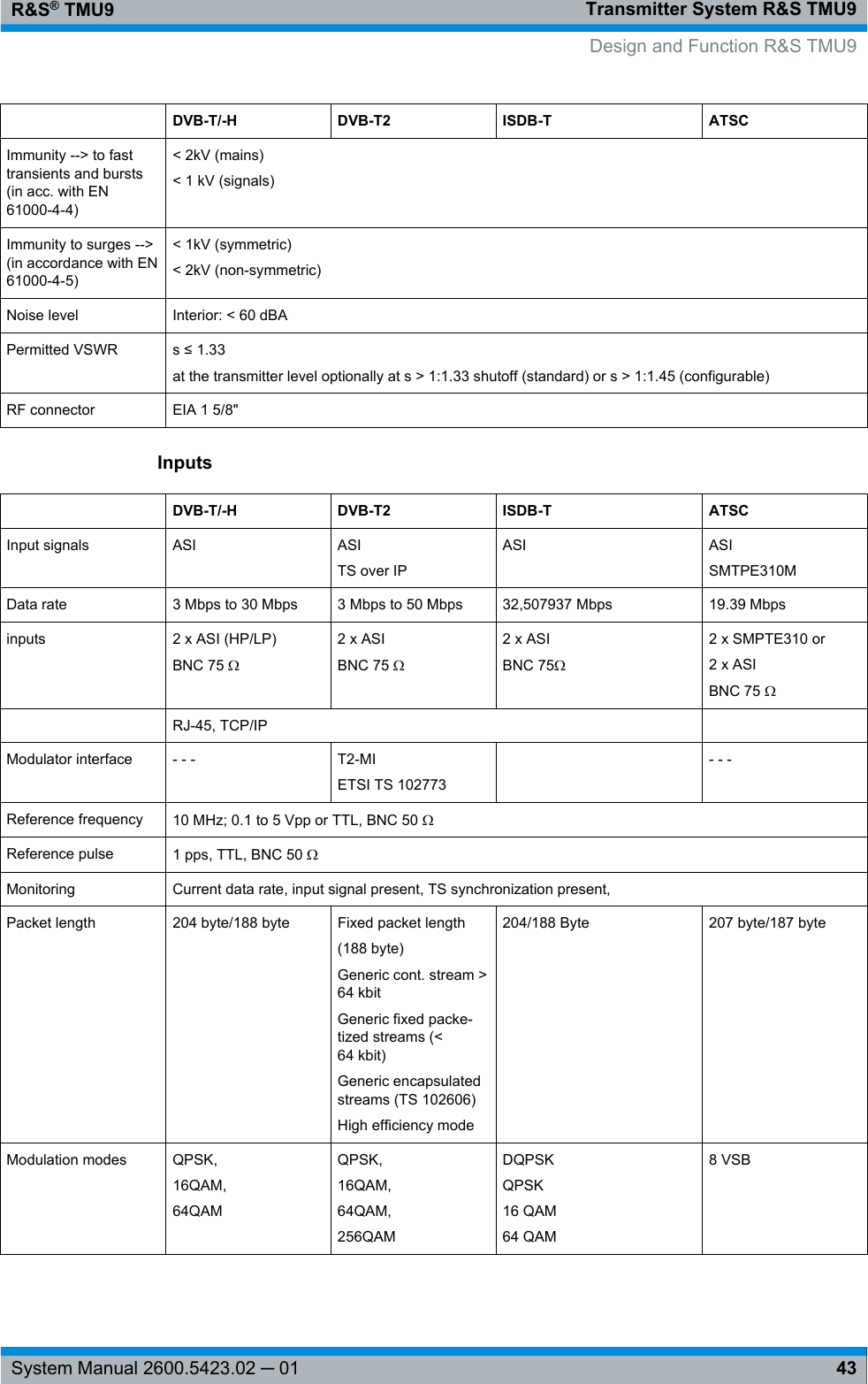
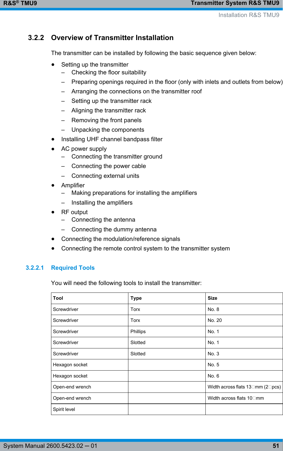
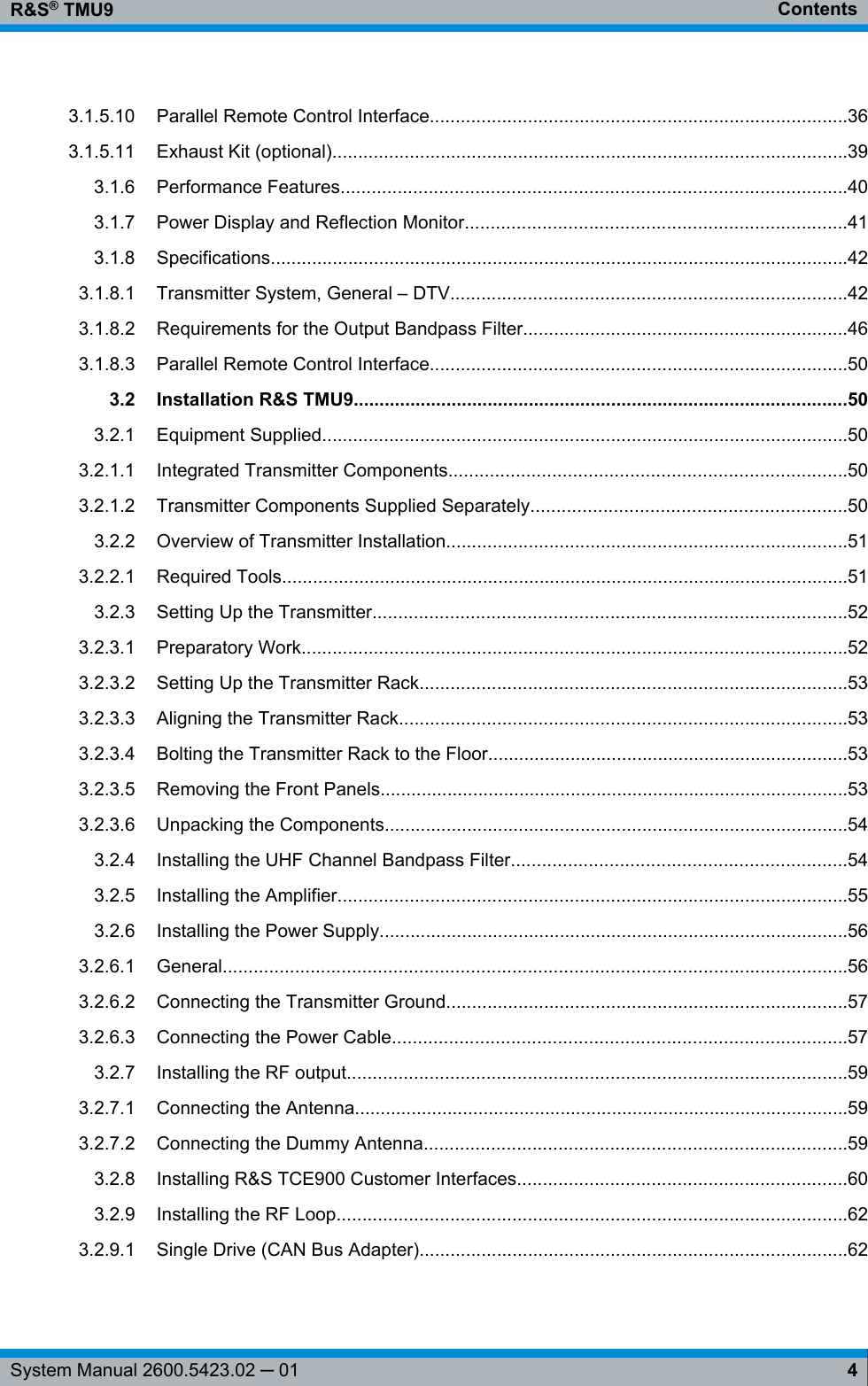
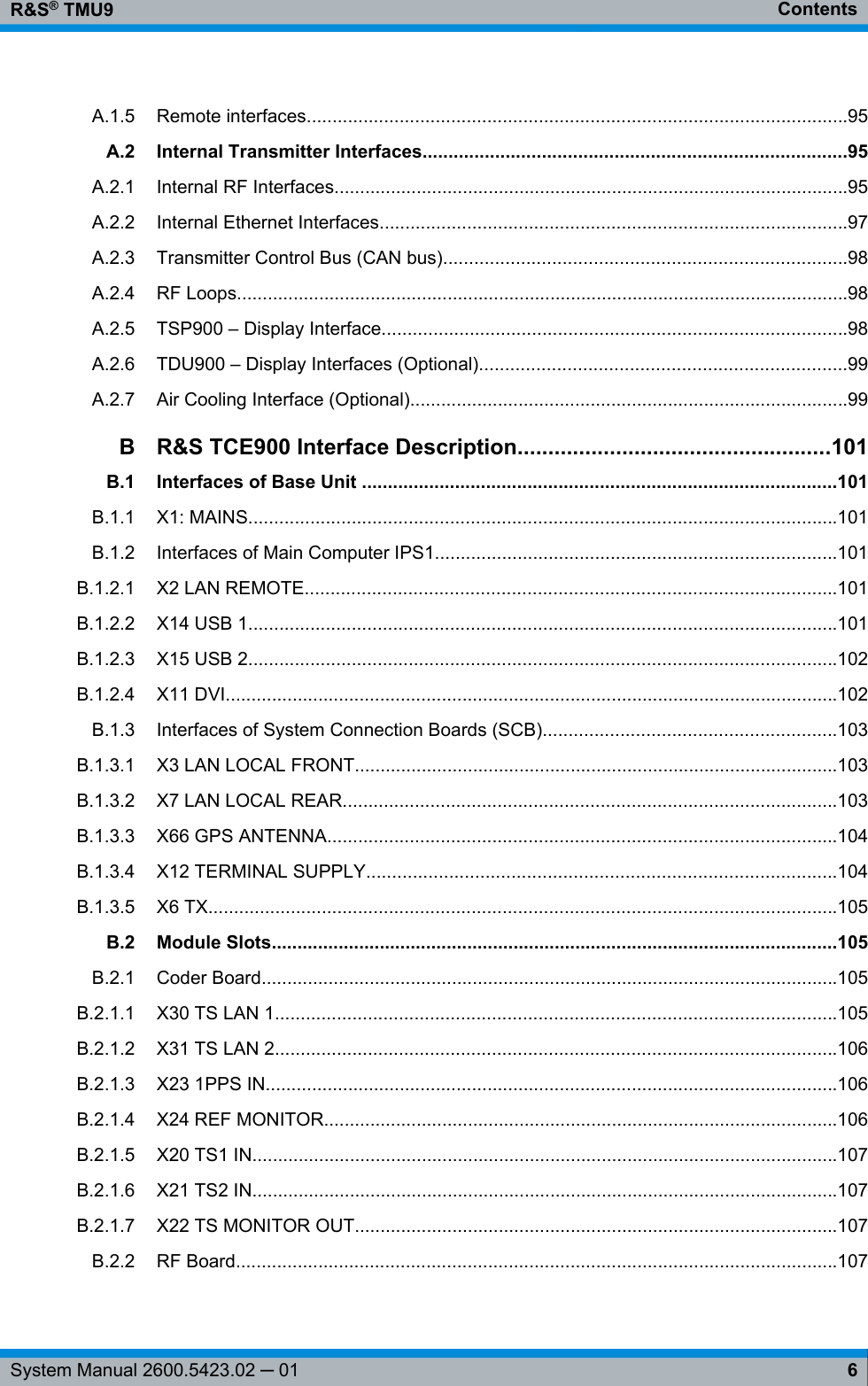
![Transmitter System R&S TMU9R&S® TMU933System Manual 2600.5423.02 ─ 01Reference OK Sum reference ofthe exciter is OKSum reference ofthe active exciteris OK [3]Sum reference ofthe active exciteris OK [3]W Sum reference ofthe exciter has aWarningSum reference ofthe active exciterhas a Warning [3]Sum reference ofthe active exciterhas a Warning [3]F Sum reference ofthe exciter has aFailSum reference ofthe active exciterhas a Fail [3]Sum reference ofthe active exciterhas a Fail [3]Off Reference signal(10 MHz/ PPS/GPS…) is notpresent and is notrequired, sincefrequency regula-tion source is setto "Manual"Reference signal(10 MHz/ PPS/GPS…) for theactive exciter isnot present and isnot required,since frequencyregulation sourceis set to "Manual"Reference signal(10 MHz/ PPS/GPS…) for theactive exciter isnot present and isnot required, sincefrequency regula-tion source is setto "Manual"RF OK Transmitter RFOKTransmitter RFOKTransmitter RFOKW Transmitter RFWarningTransmitter RFWarningTransmitter RFWarningFTransmitter RFFail [1]Transmitter RFFail [1]Transmitter RFFail [1]Off Transmitter pro-gram offTransmitter pro-gram offTransmitter pro-gram off Local TransmitterLocal/RemoteLED shows theLocal status (yel-low)TransmitterLocal/Remote(applies for pro-gram and controlexciter)LED shows theLocal status (yel-low)Transmitter Local/Remote (appliesfor Tx control,exciter A andexciter B)LED shows theLocal status (yel-low)On Transmitter On(ON/OFF com-mand acceptedby the transmit-ter)Transmitter On(ON/OFF com-mand acceptedby the transmit-ter)Transmitter On(ON/OFF com-mand accepted bythe transmitter)[1] Special case: Saved RF Fail for (switched over and) switched off transmitter[2] If an exciter switchover – called up by an incorrect input feed – already took place, thefaulty input feed to the switched-over exciter cannot be identified by the input LED.Instead, only a transmitter sum warning is displayed for the exciter automatic switchoverfunction.[3] If an exciter switchover – called up by an incorrect reference feed – already took place,the faulty reference feed to the switched-over exciter cannot be identified by the REF-Design and Function R&S TMU9](https://usermanual.wiki/Rohde-and-Schwarz/TMU925.User-Manual-Part-1/User-Guide-2289399-Page-41.png)