Rohde and Schwarz TMU925 UHF DTV ATSC 1KW TO 2.5 KW TRANSMITTER FAMILY User Manual Part 1
Rohde & Schwarz Inc UHF DTV ATSC 1KW TO 2.5 KW TRANSMITTER FAMILY Part 1
Contents
- 1. User Manual Part 1
- 2. User Manual Part 2
User Manual Part 1
R&S® TMU9
Transmitter System
System Manual
System Manual
(J0ÄG2)
2600.5423.02 ─ 01
Broadcasting
For information only!
This manual, dated December 19,
2012, reflects the technical status as of
that date. There may have been
technical changes since that time.
© 2012 Rohde & Schwarz GmbH & Co. KG
Muehldorfstr. 15, 81671 Munich, Germany
Phone: +49 89 41 29 - 0
Fax: +49 89 41 29 12 164
E-mail: info@rohde-schwarz.com
Internet: http://www.rohde-schwarz.com
Printed in Germany – Subject to change – Data without tolerance limits is not binding.
R&S® is a registered trademark of Rohde & Schwarz GmbH & Co. KG.
Trade names are trademarks of the owners.
The following abbreviations are used throughout this manual: R&S®XYZ1234 is abbreviated as R&S XYZ1234

KONFORMITÄTSERKLÄRUNG gemäß dem Gesetz über Funkanlagen und Telekommunikationsendeinrichtungen (FTEG)
und der Richtlinie 1999/5/EG (R&TTE) Anhang V, zertifiziert durch die Benannte Stelle CETECOM ICT Services GmbH,
Kennnummer 0682.
DECLARATION OF CONFORMITY in accordance with the Radio and Telecommunications Terminal Equipment Act (FTEG) and Directive
1999/5/EC (R&TTE Directive) Annex V, certified by the Notified Body CETECOM ICT Services GmbH Germany, Identif. No. 0682.
ROHDE & SCHWARZ GmbH & Co. KG
Mühldorfstr. 15, D-81671 München
München, den 26. Oktober 2012 Zentrales Qualitätsmanagement GF-QP / Radde
Munich, 2012-10-26 Central Quality Management GF-QP / Radde
CE D/E-1
Vorlage: 2012_55_TMU9.doc 3573.7015.05 / ÄI 01.00
Zertifikat-Nr.: / Certificate No.: 2012-55
Hiermit wird in alleiniger Verantwortung bescheinigt, dass die Funkanlage
We herewith certify under our sole responsibility that the radio equipment
Gerätetyp
Equipment Type
Benennung
Designation
TMU9 Mittelleistungssender / Medium Power
Transmitter
Geräteklasse: / Equipment class: 2.10 (Broadcast transmitter)
bei bestimmungsgemäßer Verwendung den grundlegenden Anforderungen des § 3 und den übrigen
einschlägigen Bestimmungen des FTEG (Artikel 3 der R&TTE) entspricht.
complies with the essential requirements of §3 and the other relevant provisions of the FTEG (Article 3 of the R&TTE
Directive), when used for its intended purpose.
• Gesundheit und Sicherheit gemäß § 3 (1) 1, (Artikel 3 (1) a))
• Health and safety requirements pursuant to § 3 (1) 1, (Article 3(1) a))
• Schutzanforderungen in Bezug auf die elektromagn. Verträglichkeit § 3 (1) 2, (Artikel 3 (1) b))
• Protection requirements concerning electromagnetic compatibility § 3(1)(2), (Article 3(1)(b))
• Maßnahmen zur effizienten Nutzung des Funkfrequenzspektrums § 3 (2), (Artikel 3(2))
• Measures for the efficient use of the radio frequency spectrum § 3 (2), (Article 3(2))
• Luftschnittstelle bei Funkanlagen gemäß § 3(3), (Artikel 3(3))
• Air interface of the radio systems pursuant to § 3(3), (Article 3(3))
Angewendete harmonisierte Normen:
Harmonized standards applied: EN 60950-1: 2006
ETSI EN 301489-1 V1.9.2 (2011-09)
ETSI EN 301489-14 V1.2.1 (2003-05)
ETSI EN 302296 V1.1.1 (2005-01)
EN 61000-3-2: 2006 +A1 +A2
EN 61000-3-3: 2008
Einhaltung der grundlegenden Anforderungen auf
andere Art und Weise (hierzu verwendete
Standards/Spezifikationen):
Other means of proving conformity with the essential requirements
(standards/specifications used):
Reg TP SSB RU 005
Rec.1999/519/EG;
26. BImSchV

KONFORMITÄTSERKLÄRUNG gemäß dem Gesetz über Funkanlagen und Telekommunikationsendeinrichtungen (FTEG)
und der Richtlinie 1999/5/EG (R&TTE) Anhang V, zertifiziert durch die Benannte Stelle CETECOM ICT Services GmbH,
Kennnummer 0682.
DÉCLARATION DE CONFORMITÉ selon la loi sur les équipements radio et les équipements terminaux de télécommunications (FTEG)
ainsi que selon la Directive 1999/5/CE (Directive R&TTE) Annexe V, certifié par l'Organisme Notifié CETECOM ICT Services GmbH
Allemagne, numéro d'identification 0682.
ROHDE & SCHWARZ GmbH & Co. KG
Mühldorfstr. 15, D-81671 München
München, den 26. Oktober 2012 Zentrales Qualitätsmanagement GF-QP / Radde
Munich, le 2012-10-26 Gestion centrale de la qualité GF-QP / Radde
CE D/F-1
Vorlage: 2012_55_TMU9.doc 3573.7015.05 / ÄI 01.00
Zertifikat-Nr.: / Certificat N° : 2012-55
Hiermit wird in alleiniger Verantwortung bescheinigt, dass die Funkanlage
Par la présente, nous certifions sous notre responsabilité exclusive que l'équipement radio
Gerätetyp
Equipment Type
Benennung
Designation
TMU9 Mittelleistungssender / Émetteur moyenne
puissance
Geräteklasse: / Classe d'équipement : 2.10
bei bestimmungsgemäßer Verwendung den grundlegenden Anforderungen des § 3 und den übrigen
einschlägigen Bestimmungen des FTEG (Artikel 3 der R&TTE) entspricht.
est conforme aux prescriptions fondamentales du paragraphe 3 et aux autres prescriptions applicables de la loi susmentionnée (Article 3 de
la Directive R&TTE), à condition qu'il soit utilisé dans les conditions stipulées.
• Gesundheit und Sicherheit gemäß § 3 (1) 1, (Artikel 3 (1) a))
• Prescriptions en matière de sécurité et de santé selon le paragraphe 3 (1) 1, (Article 3 (1) a))
• Schutzanforderungen in Bezug auf die elektromagn. Verträglichkeit § 3 (1) 2, (Artikel 3 (1) b))
• Prescriptions en matière de protection relative à la compatibilité électromagnétique selon le paragraphe 3 (1) (2) (Article 3 (1) b))
• Maßnahmen zur effizienten Nutzung des Funkfrequenzspektrums § 3 (2), (Artikel 3(2))
• Mesures pour l'utilisation efficace du spectre radioélectrique le paragraphe 3 (2), (Article 3(2))
• Luftschnittstelle bei Funkanlagen gemäß § 3(3), (Artikel 3(3))
• Interface radio des équipements radio selon le paragraphe 3 (3) (Article 3 (3))
Angewendete harmonisierte Normen:
Normes harmonisées utilisées : EN 60950-1: 2006
ETSI EN 301489-1 V1.9.2 (2011-09)
ETSI EN 301489-14 V1.2.1 (2003-05)
ETSI EN 302296 V1.1.1 (2005-01)
EN 61000-3-2: 2006 +A1 +A2
EN 61000-3-3: 2008
Einhaltung der grundlegenden Anforderungen auf
andere Art und Weise (hierzu verwendete
Standards/Spezifikationen):
Autres moyens servant à établir la conformité aux prescriptions
fondamentales (normes/spécifications utilisées) :
Reg TP SSB RU 005
Rec.1999/519/EG;
26. BImSchV

2101.6093.54 - EU - D/E-2
Für Betrieb im Europäischen Wirtschaftsraum (EWR)
und zivilem Einsatz.
Hinweis gemäß dem Gesetz über "Funkanlagen und Telekommunikationsend-
einrichtungen" (FTEG) und der Europäischen Richtlinie 1999/5/EG:
Dieses Produkt darf innerhalb des EWR nicht uneingeschränkt betrieben werden, da
der verwendete Frequenzbereich auf nicht harmonisierten Bändern erfolgt. Nationale
Vorschriften / Genehmigungen sind zu beachten.
Das Gerät ist 4 Wochen vor Inverkehrbringen bei der jeweils zuständigen nationalen
Behörde für die Frequenzhoheit zu notifizieren. Informationen hierzu im Internet unter
folgender Adresse: http://europa.eu.int/comm/enterprise/rtte/spectr.htm
For operation in the European Economic Area (EEA)
and civil use.
Note pursuant to the German Radio and Telecommunications Terminal Equip-
ment Directive (FTEG) and the European R&TTE Directive 1999/5/EC:
Operation of this product within the EEA is subject to restrictions since the frequency
bands used are not harmonised. National provisions / authorizations shall be com-
plied with.
The product shall be notified to the competent national frequency management
authority four weeks before the product is put on the market.
For more information refer to: http://europa.eu.int/comm/enterprise/rtte/spectr.htm
Printed in Germany

Sehr geehrter Kunde,
Sie haben sich für den Kauf
eines Rohde & Schwarz Produk-
tes entschieden. Sie erhalten
damit ein nach modernsten Fer-
tigungsmethoden hergestelltes
Produkt. Es wurde nach den
Regeln unserer Qualitäts- und
Umweltmanagementsysteme
entwickelt, gefertigt und geprüft.
Rohde & Schwarz ist unter ande-
rem nach den Managementsys-
temen ISO 9001 und ISO 14001
zertifiziert.
Der Umwelt verpflichtet
❙Energie-efziente,
RoHS-konforme Produkte
❙Kontinuierliche
Weiterentwicklung nachhaltiger
Umweltkonzepte
❙ISO 14001-zertiziertes
Umweltmanagementsystem
Dear customer,
You have decided to buy a
Rohde & Schwarz product. This
product has been manufactured
using the most advanced meth-
ods. It was developed, manufac-
tured and tested in compliance
with our quality management
and environmental manage-
ment systems. Rohde & Schwarz
has been certified, for exam-
ple, according to the ISO 9001
and ISO 14001 management
systems.
Environmental commitment
❙Energy-efcient products
❙Continuous improvement in
environmental sustainability
❙ISO 14001-certied
environmental management
system
Cher client,
Vous avez choisi d’acheter un
produit Rohde & Schwarz. Vous
disposez donc d’un produit
fabriqué d’après les méthodes
les plus avancées. Le dévelop-
pement, la fabrication et les
tests de ce produit ont été effec-
tués selon nos systèmes de
management de qualité et de
management environnemental.
La société Rohde & Schwarz a
été homologuée, entre autres,
conformément aux systèmes
de management ISO 9001 et
ISO 14001.
Engagement écologique
❙Produits à efcience
énergétique
❙Amélioration continue de la
durabilité environnementale
❙Système de management
environnemental certié selon
ISO 14001
Certied Environmental System
ISO 14001
Certied Quality System
ISO 9001
Quality management
and environmental
management
1171.0200.11 V 05.01
1171020011
ISO-Qualitaets-Zertifikat_1171-0200-11_A4.indd 1 28.09.2012 10:25:08

1171.0200.22-06.00
Customer Support
Technical support – where and when you need it
For quick, expert help with any Rohde & Schwarz equipment, contact one of our Customer Support
Centers. A team of highly qualified engineers provides telephone support and will work with you to find a
solution to your query on any aspect of the operation, programming or applications of Rohde & Schwarz
equipment.
Up-to-date information and upgrades
To keep your instrument up-to-date and to be informed about new application notes related to your
instrument, please send an e-mail to the Customer Support Center stating your instrument and your wish.
We will take care that you will get the right information.
Europe, Africa, Middle East Phone +49 89 4129 12345
customersupport@rohde-schwarz.com
North America Phone 1-888-TEST-RSA (1-888-837-8772)
customer.support@rsa.rohde-schwarz.com
Latin America Phone +1-410-910-7988
customersupport.la@rohde-schwarz.com
Asia/Pacific Phone +65 65 13 04 88
customersupport.asia@rohde-schwarz.com
China Phone +86-800-810-8228 /
+86-400-650-5896
customersupport.china@rohde-schwarz.com

Contents
R&S® TMU9
3System Manual 2600.5423.02 ─ 01
Contents
1Information about this Manual..............................................................9
2 Safety Instructions...............................................................................11
2.1 Safety Instructions for Transmitter Systems and Equipment................................11
2.2 General Safety Instructions.......................................................................................12
2.2.1 Safety Instructions.........................................................................................................12
2.3 Special Hazard Information........................................................................................19
2.3.1 Hazards from AC Supply Voltage.................................................................................19
2.3.1.1 AC Power Supply..........................................................................................................19
2.3.1.2 Changing Fuses............................................................................................................19
2.3.2 Hazards from High‑Energy Electric Circuits..................................................................19
2.3.3 Hazards from RF Radiation...........................................................................................20
2.3.3.1 Obligation to Instruct Personnel....................................................................................20
2.3.3.2 RF Shielding..................................................................................................................20
2.3.3.3 Rules When Operating an Amplifier..............................................................................20
2.3.3.4 Rules When Working on an Open Amplifier..................................................................21
3Transmitter System R&S TMU9..........................................................23
3.1 Design and Function R&S TMU9...............................................................................23
3.1.1 Rack Design..................................................................................................................23
3.1.2 Arrangement of the R&S TCE900 Instruments and System Components....................23
3.1.3 Redundancy Concepts..................................................................................................25
3.1.4 Applications...................................................................................................................28
3.1.5 Overview of Modules and Devices................................................................................30
3.1.5.1 Mains Distribution Unit..................................................................................................30
3.1.5.2 Transmitter Control Unit................................................................................................31
3.1.5.3 TSP900 (Transmitter Status Panel)..............................................................................32
3.1.5.4 Exciter and System Components..................................................................................34
3.1.5.5 Output Stage Unit..........................................................................................................34
3.1.5.6 OSKAR Coupler Module...............................................................................................35
3.1.5.7 External Directional Coupler (GD901/902)....................................................................35
3.1.5.8 Bandpass Filter.............................................................................................................35
3.1.5.9 RF Connector................................................................................................................36

Contents
R&S® TMU9
4System Manual 2600.5423.02 ─ 01
3.1.5.10 Parallel Remote Control Interface.................................................................................36
3.1.5.11 Exhaust Kit (optional)....................................................................................................39
3.1.6 Performance Features..................................................................................................40
3.1.7 Power Display and Reflection Monitor..........................................................................41
3.1.8 Specifications................................................................................................................42
3.1.8.1 Transmitter System, General – DTV.............................................................................42
3.1.8.2 Requirements for the Output Bandpass Filter...............................................................46
3.1.8.3 Parallel Remote Control Interface.................................................................................50
3.2 Installation R&S TMU9................................................................................................50
3.2.1 Equipment Supplied......................................................................................................50
3.2.1.1 Integrated Transmitter Components.............................................................................50
3.2.1.2 Transmitter Components Supplied Separately.............................................................50
3.2.2 Overview of Transmitter Installation..............................................................................51
3.2.2.1 Required Tools..............................................................................................................51
3.2.3 Setting Up the Transmitter............................................................................................52
3.2.3.1 Preparatory Work..........................................................................................................52
3.2.3.2 Setting Up the Transmitter Rack...................................................................................53
3.2.3.3 Aligning the Transmitter Rack.......................................................................................53
3.2.3.4 Bolting the Transmitter Rack to the Floor......................................................................53
3.2.3.5 Removing the Front Panels...........................................................................................53
3.2.3.6 Unpacking the Components..........................................................................................54
3.2.4 Installing the UHF Channel Bandpass Filter.................................................................54
3.2.5 Installing the Amplifier...................................................................................................55
3.2.6 Installing the Power Supply...........................................................................................56
3.2.6.1 General.........................................................................................................................56
3.2.6.2 Connecting the Transmitter Ground..............................................................................57
3.2.6.3 Connecting the Power Cable........................................................................................57
3.2.7 Installing the RF output.................................................................................................59
3.2.7.1 Connecting the Antenna................................................................................................59
3.2.7.2 Connecting the Dummy Antenna..................................................................................59
3.2.8 Installing R&S TCE900 Customer Interfaces................................................................60
3.2.9 Installing the RF Loop...................................................................................................62
3.2.9.1 Single Drive (CAN Bus Adapter)...................................................................................62

Contents
R&S® TMU9
5System Manual 2600.5423.02 ─ 01
3.2.9.2 Dual Drive (RF Switch)..................................................................................................63
3.2.10 Installing the TM9-C1 Exhaust Kit.................................................................................63
3.3 Commissioning R&S TMU9........................................................................................65
4Exciter/Transmitter Control R&S TCE900..........................................67
4.1 Design and Function R&S TCE900............................................................................67
4.1.1 R&S TCE900 General Design.......................................................................................67
4.1.2 R&S TCE900 Functions................................................................................................71
5Amplifier R&S PMU901........................................................................73
5.1 Design and Function R&S PMU901...........................................................................73
5.1.1 Device Purpose and Overview......................................................................................73
5.1.2 Mechanical Design........................................................................................................74
5.1.3 Display Elements and Interfaces...................................................................................77
5.1.3.1 LEDs and Test Point – Front Panel...............................................................................77
5.1.3.2 Connectors – Rear Panel..............................................................................................79
5.1.4 Circuit Descriptions.......................................................................................................81
5.1.4.1 Block Diagram...............................................................................................................81
5.1.4.2 Signal Gain in Preamplifier and Driver..........................................................................81
5.1.4.3 Signal Gain in Doherty-Capable Output Stage.............................................................82
5.1.4.4 Power Control...............................................................................................................83
5.1.4.5 Self‑Protection Mechanisms..........................................................................................84
5.1.4.6 Emergency Shutdown...................................................................................................86
5.1.5 Specifications................................................................................................................86
5.1.5.1 General Data.................................................................................................................86
5.1.5.2 Digital TV (DTV)............................................................................................................87
5.1.5.3 Analog TV (ATV Combined)..........................................................................................88
5.1.5.4 CW Mode......................................................................................................................88
AR&S TMU9 Interface Description........................................................91
A.1 External Transmitter Interfaces.................................................................................91
A.1.1 Transmitter Input AC.....................................................................................................91
A.1.2 Input Signals (TS, RF, Reference)................................................................................91
A.1.3 Transmitter Output........................................................................................................94
A.1.4 Monitoring Signals (TS, RF, Reference).......................................................................94

Contents
R&S® TMU9
6System Manual 2600.5423.02 ─ 01
A.1.5 Remote interfaces.........................................................................................................95
A.2 Internal Transmitter Interfaces..................................................................................95
A.2.1 Internal RF Interfaces....................................................................................................95
A.2.2 Internal Ethernet Interfaces...........................................................................................97
A.2.3 Transmitter Control Bus (CAN bus)..............................................................................98
A.2.4 RF Loops.......................................................................................................................98
A.2.5 TSP900 – Display Interface..........................................................................................98
A.2.6 TDU900 – Display Interfaces (Optional).......................................................................99
A.2.7 Air Cooling Interface (Optional).....................................................................................99
BR&S TCE900 Interface Description...................................................101
B.1 Interfaces of Base Unit ............................................................................................101
B.1.1 X1: MAINS..................................................................................................................101
B.1.2 Interfaces of Main Computer IPS1..............................................................................101
B.1.2.1 X2 LAN REMOTE.......................................................................................................101
B.1.2.2 X14 USB 1..................................................................................................................101
B.1.2.3 X15 USB 2..................................................................................................................102
B.1.2.4 X11 DVI.......................................................................................................................102
B.1.3 Interfaces of System Connection Boards (SCB).........................................................103
B.1.3.1 X3 LAN LOCAL FRONT..............................................................................................103
B.1.3.2 X7 LAN LOCAL REAR................................................................................................103
B.1.3.3 X66 GPS ANTENNA...................................................................................................104
B.1.3.4 X12 TERMINAL SUPPLY...........................................................................................104
B.1.3.5 X6 TX..........................................................................................................................105
B.2 Module Slots..............................................................................................................105
B.2.1 Coder Board................................................................................................................105
B.2.1.1 X30 TS LAN 1.............................................................................................................105
B.2.1.2 X31 TS LAN 2.............................................................................................................106
B.2.1.3 X23 1PPS IN...............................................................................................................106
B.2.1.4 X24 REF MONITOR....................................................................................................106
B.2.1.5 X20 TS1 IN..................................................................................................................107
B.2.1.6 X21 TS2 IN..................................................................................................................107
B.2.1.7 X22 TS MONITOR OUT..............................................................................................107
B.2.2 RF Board.....................................................................................................................107

Contents
R&S® TMU9
7System Manual 2600.5423.02 ─ 01
B.2.2.1 X64 REF IN.................................................................................................................107
B.2.2.2 X60 RF OUT...............................................................................................................108
B.2.2.3 X61 RF MONITOR OUT.............................................................................................108
B.2.2.4 X67 RF DOWNCONVERTER 1 IN.............................................................................108
B.2.2.5 X68 RF DOWNCONVERTER 2 IN.............................................................................108
B.2.3 Tx Interface.................................................................................................................109
B.2.3.1 X40 LAN 1...................................................................................................................109
B.2.3.2 X41 LAN 2...................................................................................................................109
B.2.3.3 X42 LAN 3...................................................................................................................110
B.2.3.4 X43 LAN 4...................................................................................................................110
B.2.3.5 X44 Power Distributor.................................................................................................111
B.2.3.6 X45 Rf Switch PAR IO................................................................................................112
B.2.4 Cooling Interface (CIF)................................................................................................113
B.2.4.1 X46 Pump...................................................................................................................113
B.2.4.2 X47 HEX.....................................................................................................................114
B.2.5 Air Cooling Interface (Optional)...................................................................................116
B.2.5.1 Connection to Exhaust Fan, Differential Pressure Sensor, X46 FAN1.......................116
B.2.5.2 Connection to Exhaust Fan, Differential Pressure Sensor, X47 FAN2.......................116
CR&S PMU901 Interface Description..................................................119
C.1 X1: Supply Input; Schaltbau M3 connector............................................................119
C.2 X2: RF Output 7/16 - Socket (Rear)..........................................................................120
C.3 X3: RF Test Socket; SMA Female (Front)...............................................................120
C.4 X10: RF Input SMA Female (Rear)...........................................................................120
C.5 X13: Second RF Test Socket for ADE; SMA Female (Rear)..................................121
C.6 X22: Fan Connection 1; 4-pin Molex Connector....................................................121
C.7 X23: Fan Connection 2; 4-pin Molex Connector....................................................121
C.8 X11: Amplifier Control Unit; 15-pin D-Sub connector (rear).................................122

Contents
R&S® TMU9
8System Manual 2600.5423.02 ─ 01

Information about this Manual
R&S® TMU9
9System Manual 2600.5423.02 ─ 01
1 Information about this Manual
This manual is part of the documentation for the R&S TMU9 transmitter family from
Rohde & Schwarz. The individual manuals for the transmitter family have a modular
structure and complement each other.
Structure
The system manual, which is the central and overarching part of the overall documen-
tation, describes all the steps involved in installing a transmitter.
Operation of the transmitter system after installation and the steps required to put the
system into operation are described in the operating manual.
The service manual describes all maintenance, troubleshooting and service tasks that
customers can carry out themselves. At certain points in the transmitter manual, the
reader is referred to the appropriate operating manual or service manual.
Contents
The manuals for the transmitter family describe all activities required for installation,
startup, operation, maintenance, troubleshooting and servicing of the transmitter and its
component parts. The appendix contains the interface descriptions and the technical
documentation.
Safety
All skilled personnel working with a transmitter or its components have a duty to read the
associated manuals and to follow the safety measures described in the section "Safety"
and given at appropriate points in the manual. It must be ensured that the transmitter and
the individual components of the transmitter are used only for their intended purpose. All
activities connected with the transmitter or individual transmitter components must be
carried out by skilled personnel. If activities require additional skills and qualifications,
this is indicated at the appropriate points in the manual.
Symbols and notation
The warning triangle symbol refers the reader to potential hazards. The degree of danger
is indicated by different signal words next to the warning symbol.
Instructions are given in numbered steps. All other formatting options are intended to
improve clarity and are self‑explanatory.

Information about this Manual
R&S® TMU9
10System Manual 2600.5423.02 ─ 01

Safety Instructions
R&S® TMU9
11System Manual 2600.5423.02 ─ 01
2 Safety Instructions
2.1 Safety Instructions for Transmitter Systems and Equip-
ment
Compliance with safety regulations
The safety regulations specified in this manual must always be complied with.
The following points require special attention:
●Only qualified technicians are allowed to install and wire the electrical equipment.
●National and international safety rules and regulations must be observed when
equipping operating facilities and during the assembly and operation of electrical
systems.
These include, for example:
– Protective measures to prevent accidents
– Protection against overvoltage
– Isolation of electrical systems
– Grounding of electrical systems
– Physical properties and laying of electrical lines and cables
– Regulations that apply to factories, work areas and special systems
●When installing transmitter racks, it is important to observe national accident pre-
vention regulations, for example, with regard to:
– Crushing hazard when working beneath suspended loads
– Fall hazards when working on ladders
– Risk of injury when lifting heavy loads
●Personal protective equipment (PPE) must be used when installation or repair work
is being carried out. Depending on the type of work, it may be necessary to wear
protective clothing such as hard hats, safety gloves, eye protection, etc.
●Instruments and systems must not be operated unless their cabinets are closed.
Observe the appropriate safety instructions when opening cabinets for maintenance
or repair work.
●Isolate all poles when disconnecting instruments and systems from the AC supply.
In addition, disconnect all external sources of power, i.e. all measuring cables, exten-
sion cables and multipoint connectors (except for special service connectors). Then
wait approx. 5 minutes to ensure that the capacitors in the system are sufficiently
discharged.
●Additional information on liquid‑cooled transmitters: When installing the cooling sys-
tem and filling it with coolant (pump and heat exchanger), the applicable regulations
Safety Instructions for Transmitter Systems and Equipment

Safety Instructions
R&S® TMU9
12System Manual 2600.5423.02 ─ 01
on working with hazardous products (coolant) must be observed; see the section
"Material Safety Data Sheets" under "EC Safety Data Sheet – Antifrogen".
2.2 General Safety Instructions
This section contains general safety instructions applying to all products manufactured
or sold by Rohde & Schwarz.
In accordance with IEC215 or EN60215, transmitter systems and their add-on equipment
must be operated under the responsibility of qualified technicians only. The minimum
requirements for qualified electricians are also defined in the standard "Safety require-
ments for radio transmitting equipment".
Compliance with all legal and regulatory requirements is a precondition for operating radio
equipment and systems. The operator or the operator's authorized representative is
responsible for ensuring compliance with these requirements. They must additionally
ensure that the training of the operating personnel satisfies the country-specific require-
ments. This includes any periodic training that is necessary.
2.2.1 Safety Instructions
It is essential to read and observe the following instructions and safety informa-
tion.
All factories and sites of the Rohde & Schwarz company group continuously strive to
ensure that our products meet the very latest safety standards and that our customers
are provided with the highest possible degree of safety. Our products and any additional
equipment that they require are manufactured and tested in accordance with the appli-
cable safety regulations. Our quality assurance department regularly checks if these
standards are met. This product has been manufactured and tested in accordance with
the enclosed EC Certificate of Conformity and left the factory in a condition fully complying
with the relevant safety standards. In order to keep the product in this condition and to
ensure that it operates safely, the user must observe all information, warnings and
instructions. Please do not hesitate to contact the Rohde & Schwarz company group if
you have any queries regarding these safety instructions.
Additionally, it is the responsibility of the user to ensure that the product is operated in
the appropriate manner. The product is intended for industrial and laboratory use only
and, if expressly authorized, also for use in the field, and must never be used in such a
way that may result in injury to personnel or damage to property. The user shall be held
responsible if the product is used for purposes other than those specified or in such a
way that disregards the instructions from the manufacturer. The manufacturer shall not
be liable for any consequences resulting from the product being used for purposes other
than those for which it is intended.
Use of the product for its intended purpose is assumed if the product is used in accord-
ance with the specifications given in the associated product documentation and within its
performance limits (see the data sheet, documentation and the following safety instruc-
General Safety Instructions
Safety Instructions
R&S® TMU9
13System Manual 2600.5423.02 ─ 01
tions). Use of the product requires specialist knowledge and, in part, knowledge of the
English language. It is therefore important to ensure that the product is operated only by
specialist personnel and persons with the appropriate skills who have received detailed
instruction in how to operate the product. If personnel protective equipment is required
for the operation of Rohde & Schwarz products, this is indicated at the appropriate point
in the product documentation. Keep the basic safety instructions and product documen-
tation in a safe place and pass them on to subsequent users of the product.
Observance of the safety instructions is intended to prevent injury or damage resulting
from hazards of all types. It is therefore necessary that intended users carefully read and
understand the following safety instructions before and during use of the product. It is
also essential to observe all other safety instructions (e.g. relating to personnel protection)
which are given at appropriate points in the product documentation. In these safety
instructions, the term "product" refers to all articles sold and marketed by the
Rohde & Schwarz company group; these include instruments, installations and all acces-
sory items.
Signal words and their meaning
The following signal words are used in the product documentation to warn of risks and
hazards.
indicates an immediate high-risk hazard which will result in death or serious injury if it is
not avoided.
indicates a potential medium-risk hazard which can result in death or (serious) injury if it
is not avoided.
indicates a low-risk hazard which could result in minor or medium injury if it is not avoided.
indicates possible incorrect operation which could result in damage to the product.
These signal words correspond to the definitions customary in the European Economic
Area for civil applications. In addition to this definition, there may also be varying defini-
tions used in other economic areas or for military applications. It is therefore important to
note that the signal words described here are used only in connection with the associated
product documentation and the associated product. The use of signal words in connection
General Safety Instructions

Safety Instructions
R&S® TMU9
14System Manual 2600.5423.02 ─ 01
with non-associated products or non-associated documentation can lead to incorrect
interpretation and thus result in injury and damage.
Operating conditions, positions and locations
The product should only be operated in the operating conditions, positions and locations
specified by the manufacturer such that ventilation is not obstructed. Non-observance of
the manufacturer specifications can result in electric shock, fire and/or serious or (under
certain circumstances) fatal injury. All work must be performed in compliance with the
local or country-specific safety and accident prevention regulations.
1. Unless otherwise agreed, the following points apply for Rohde & Schwarz products:
a) Operating position: housing base at bottom
b) IP degree of protection: 2 x USB 2.0 for connecting an external mouse, keyboard,
USB stick, etc.
c) Degree of soiling: 2
d) Overvoltage category: 2
e) For indoor use only
f) Operation up to 2000 m above sea level
g) Transport up to 4500 m above sea level
h) Tolerance for nominal voltage: ± 10 %
i) Tolerance for nominal frequency: ± 5 %
2. Do not stand the product on surfaces, vehicles, shelves or tables that are not suitable
for weight or stability reasons. When mounting and securing the product on/to objects
or structures (e.g. walls and shelves), always follow the installation instructions from
the manufacturer. Persons can be injured or even killed if installation is not performed
in the way described in the product documentation.
3. Do not place the product on appliances that generate heat (e.g. radiators and fan
heaters). The ambient temperature must not exceed the maximum temperature
specified in the product documentation or in the data sheet. Overheating of the prod-
uct can result in electric shock, fire and/or serious or (under certain circumstances)
fatal injury.
Electrical safety
Non-observance or inadequate observance of the instructions concerning electrical
safety can result in electric shock, fire and/or serious or (under certain circumstances)
fatal injury.
1. Before switching on the product, always make sure that the nominal voltage set at
the product matches the nominal AC voltage of power supply network. If it is neces-
sary to change the voltage setting, it may also be necessary to change the associated
AC supply fuse of the product.
2. In the case of products of protection class I with movable power supply line and plug
connector, operation is only permitted at sockets with protective contact and con-
nected PE conductor.
General Safety Instructions

Safety Instructions
R&S® TMU9
15System Manual 2600.5423.02 ─ 01
3. Any deliberate interruption of the PE conductor (both along the feed line and at the
product itself) is not permitted. This can result in a potential shock hazard at the
product. If extension cables or multipoint connectors are used, it must be ensured
that their safety is checked at regular intervals.
4. If the product is not equipped with a power switch to disconnect it from the power
supply, the plug on the connecting cable must be used to disconnect the power sup-
ply. In such cases, it must be ensured that the power plug is easily reachable and
accessible at all times (length of connecting cable approx. 2 m). Function switches
or electronic switches are not suitable for disconnecting the product from the power
supply. If products without power switch are integrated in racks or systems, the dis-
connecting device must be provided at system level.
5. Never use the product if the power cable is damaged. Check at regular intervals that
the power cable is in perfect condition. Take suitable precautions and use suitable
cable installation methods to ensure that the power cable cannot be damaged and
personnel cannot be injured (e.g. as a result of electric shock or tripping over cables).
6. Operation is only permitted in TN/TT supply networks which are fuse-protected with
max. 16 A (higher fuse ratings should only be used after consultation with the
Rohde & Schwarz company group).
7. Do not insert the plug into dusty or dirty sockets. Insert the plug firmly and completely
into the sockets provided. Disregard of these points can lead to sparks, fire and/or
injury.
8. Do not overload the sockets, extension cables or multipoint connectors as this can
cause fire or electric shocks.
9. In the case of measurements in electrical circuits with voltages Urms > 30 V, appro-
priate measures must be taken to avoid all hazards (e.g. suitable measuring equip-
ment, fuse protection, current limiting, electrical separation, insulation, etc.).
10. In the case of connections to IT equipment (e.g. PCs or industrial computers), it must
be ensured that such connections satisfy the applicable IEC60950‑1/EN60950‑1 or
IEC61010‑1/EN61010‑1.
11. Unless explicitly permitted, never remove the cover or any part of the housing while
the product is in operation. Electrical lines and components will otherwise be
exposed, which can lead to injury, fire or damage to the product.
12. If the product is connected at a fixed location, the connection between the on‑site PE
conductor connection and the instrument PE conductor must be set up before any
other connections are made. Installation and connection should only be performed
by an electrician.
13. In the case of permanently installed equipment without built‑in fuses, circuit breakers
or similar protective devices, the supply circuit must be fused in such a way that
personnel who have access to the product, as well as the product itself, are ade-
quately protected.
General Safety Instructions

Safety Instructions
R&S® TMU9
16System Manual 2600.5423.02 ─ 01
14. Every product must be protected against overvoltage (e.g. as a result of a lightning
strike) by means of appropriate overvoltage protection. The operating personnel are
otherwise at risk of electric shock.
15. Foreign objects must not be inserted into the openings of the housing. This can cause
short circuits in the product and/or electric shocks, fire or injury.
16. Unless otherwise specified, products are not protected against the penetration of
fluids; see also the section "Operating conditions, positions and locations", point 1.
The instruments must therefore be protected against the penetration of fluids. If this
point is disregarded, there is a risk of electric shock for the user or of damage to the
product, which in turn can also endanger personnel.
17. Do not use the product under conditions in which condensation could occur (or may
already have occurred) in or on the product, e.g. if the product has been moved from
a cold environment into a warm environment. Water penetration increases the risk of
electric shock.
18. Before cleaning the product, fully disconnect it from the power supply (e.g. power
supply network or battery). Clean instruments using a soft, lint-free dust cloth. Never
use chemical cleaning agents such as alcohol, acetone or cellulose thinner.
Operation
1. Use of the product requires special instruction and full concentration during use. It
must be ensured that persons who operate the product are fit to do so from a physical,
intellectual and mental viewpoint, otherwise there is a risk of injury or damage. It is
the responsibility of the employer/operator to select suitable personnel to use the
product.
2. Before moving or transporting the product, read and observe the information in the
section "Transport" on page 18.
3. As with all industrially manufactured goods, it is not possible to completely rule out
the use of materials which cause allergies, i.e. "allergens" (e.g. nickel). If, when using
Rohde & Schwarz products, allergic reactions occur (e.g. skin rash, frequent sneez-
ing, red eyes or respiratory problems), consult a doctor immediately in order to deter-
mine the cause and to prevent health problems.
4. Before mechanically and/or thermally processing or dismantling the product, it is
essential to refer to the section "Disposal" on page 18, point 1.
5. Owing to the inherent functional design of certain products (e.g. RF radio systems),
increased electromagnetic radiation may be produced. In order to protect unborn life,
pregnant women must be protected by means of suitable measures. Electromagnetic
radiation also poses a risk to persons with pacemakers. The employer/operator is
obliged to assess and identify workplaces where there is a particular risk of exposure
to radiation, and to take precautions to prevent potential hazards.
General Safety Instructions

Safety Instructions
R&S® TMU9
17System Manual 2600.5423.02 ─ 01
6. In the event of fire, toxic substances (gases, fluids, etc.) can be discharged from the
product and damage the health of personnel. If a fire occurs, appropriate measures
must therefore be taken (e.g. breathing masks and protective clothing).
7. If a laser product is integrated in an Rohde & Schwarz product (e.g. CD/DVD drive),
no settings or functions other than those described in the product documentation
should be used in order to prevent injury (e.g. from the laser beam).
Repair and servicing
1. The product should be opened by authorized specialist personnel only. Before any
work is performed on the product or before the product is opened, it must be discon-
nected from the supply voltage, otherwise there is a risk of electric shock.
2. Any adjustments, part replacements, maintenance or repairs should be carried out
only by authorized Rohde & Schwarz electricians. If safety‑relevant parts (e.g. power
switches, power transformers or fuses) are to be changed, they must always be
replaced with original parts. A safety check must be performed after safety‑relevant
parts have been replaced (visual inspection, PE conductor test, insulation resistance
measurement, leaking current measurement, functional check). This ensures that the
product remains safe to use.
Batteries and rechargeable batteries/cells
Non-observance or inadequate observance of the instructions concerning electrical
safety can result in electric shock, fire and/or serious or (under certain circumstances)
fatal injury.Batteries and rechargeable batteries with alkaline electrolyte (e.g. lithium
cells) must be handled in line with EN62133.
1. Cells must not be disassembled, opened or crushed.
2. Lithium batteries must not be exposed to high temperatures or fire. Do not store or
place batteries in direct sunlight. Keep cells and batteries clean and dry. Clean dirty
terminals using a dry, clean cloth.
3. Cells and batteries must not be short-circuited. Cells and batteries must not be stored
in a potentially hazardous manner in a box or drawer where they can short-circuit
each other or can be short-circuited by other conductive materials. A cell or battery
should only be taken out of its original packaging when it is to be used.
4. Keep cells and batteries out of the reach of children. If a cell or battery has been
swallowed, seek medical assistance immediately.
5. Do not subject cells and batteries to severe mechanical jolts or impacts.
6. If a cell is leaking, do not allow the fluid to come into contact with the skin or eyes. If
the fluid does come into contact with the skin or eyes, wash the affected area with
plenty of water and seek medical assistance.
7. There is a risk of explosion if cells or batteries containing alkaline electrolyte (e.g.
lithium cells) are replaced or charged incorrectly. To ensure that the product remains
General Safety Instructions

Safety Instructions
R&S® TMU9
18System Manual 2600.5423.02 ─ 01
safe to use, always replace cells or batteries with the appropriate R&S type (see the
replacement parts list).
8. Cells or batteries must be recycled and must not be disposed of with residual waste.
Rechargeable batteries or batteries containing lead, mercury or cadmium must be
disposed of as special waste. Observe the country‑specific disposal and recycling
regulations.
Transport
1. The product can be extremely heavy. It must therefore be moved and transported
carefully and, if necessary, using suitable lifting gear (e.g. lift truck) in order to prevent
injuries to the back and other parts of the body.
2. Handles on the products are handling aids which are only intended for persons trans-
porting the product. The handles are not to be used for securing the product to or on
transport equipment (e.g. cranes, forklift trucks, carts, etc.). It is your responsibility to
ensure that the products are attached securely to or on suitable transport or lifting
equipment. Observe the safety regulations from the manufacturer of the used trans-
port or lifting equipment in order prevent injury to personnel and damage to the prod-
uct.
3. If you use the product in a vehicle, it is the responsibility of the driver to drive the
vehicle in a safe and appropriate manner. The manufacturer shall not be liable for
accidents or collisions. Never use the product in moving vehicle if there is a risk that
this could distract the vehicle driver. Make sure that the product is adequately secured
in order to prevent injury or further damage in the event of an accident.
Disposal
1. If products or their components are processed mechanically and/or thermally beyond
the scope of the operating conditions for which they were intended, hazardous mate-
rials (dust containing heavy metals such as lead, beryllium, nickel) can be released.
The product should therefore be dismantled by specially trained personnel only.
Incorrect dismantling can cause damage to health. The national regulations con-
cerning disposal must be observed.
2. If, when handling the product, hazardous materials or operating fluids are encoun-
tered which must be disposed of separately (e.g. coolant or engine oils that have to
be changed at regular intervals), the safety instructions from the manufacturer of
these hazardous materials and operating fluids, and the applicable local disposal
regulations must be observed. Also observe any additional relevant safety instruc-
tions in the product documentation. Incorrect disposal of hazardous materials or
operating fluids can result in damage to health and the environment.
General Safety Instructions

Safety Instructions
R&S® TMU9
19System Manual 2600.5423.02 ─ 01
2.3 Special Hazard Information
2.3.1 Hazards from AC Supply Voltage
All voltages of Urms > 30 V AC or U > 60 V DC must be regarded as constituting a shock
hazard. When working with voltages that constitute a shock hazard, appropriate meas-
ures must be taken to prevent exposure to danger. Never work on live components. Work
on live parts should only be performed in exceptional cases and only if special safety
precautions are taken.
2.3.1.1 AC Power Supply
●Before connecting the AC power supply, it is important to ensure that the power sup-
ply specifications given for the system or instruments match the nominal specifica-
tions for the local power supply network. The power supply circuit must be protected
by means of fuses in order to prevent overloads and short circuits.
●Miniature modules have neutral conductor fuses. As a result, the power supply may
still be connected even after interruption of the circuit by a fuse.
2.3.1.2 Changing Fuses
●Fuses which are accessible to the operator should only be changed after the instru-
ments have been disconnected from the power supply. They must always be replaced
with fuses that have the same electrical rating, tripping characteristics and breaking
capacity.
●Motor protection switches and automatic line fuses in those parts of a transmitter
system that can be accessed by users must be tripped. If their response range is
adjustable, the ex‑factory setting must not be altered. If settings are changed inad-
vertently, the correct values specified in this documentation must be set.
2.3.2 Hazards from High‑Energy Electric Circuits
The instruments contain low-voltage circuits that can be fed from a voltage source with
an extremely low impedance (e.g. amplifier operating voltage). These circuits carry dan-
gerously high levels of energy. At Rohde & Schwarz, we treat these circuits in the same
way as circuits with hazardous contact voltages. Normally, these circuits are protected
by covers to prevent unintentional contact. The cover has a warning label.
In practice it has been repeatedly shown that short circuits caused by small metallic tools
result in severe burns. For safety reasons, any high‑energy electric circuits in areas of
the equipment that can be accessed by users are concealed by protective covers.
●Exercise the same amount of caution for measurements on low‑impedance voltages
(e.g. for repair purposes) that you would when performing measurements on oper-
ating voltages which constitute a shock hazard.
Wear suitable protective gear when necessary.
Special Hazard Information

Safety Instructions
R&S® TMU9
20System Manual 2600.5423.02 ─ 01
●Before opening any equipment or removing a particular cover, turn off the power
supply and wait 5 minutes to ensure that capacitors have discharged sufficiently.
●Do not discharge capacitors by short‑circuiting them.
2.3.3 Hazards from RF Radiation
2.3.3.1 Obligation to Instruct Personnel
●The operator must train all personnel in the operation of this transmitter or instrument
in line with EN60215 and/or IEC215. It is essential that these regular training sessions
emphasize the dangers related to high frequency that exist at the respective trans-
mitter or instrument. Operating personnel are only authorized to adjust and operate
the equipment after they have completed the respective training sessions and their
participation has been documented.
High‑energy RF circuits inside the transmitter or instrument are routed via conventional
removable RF connectors (e.g. type N). Depending on the output power, the output ports
of the transmitter and instrument are equipped with screw-type or plug-in RF lines or
ducts.
If RF lines or modules carry high power, the connection point or the entire module is
tagged with the general danger warning label (yellow triangle with a black exclamation
mark).
2.3.3.2 RF Shielding
Transmitters and instruments from Rohde & Schwarz are shielded so that even in the
immediate vicinity there is no danger from RF radiation when all RF lines are connected.
This applies to statutory provisions in Germany, i.e. the regulation concerning electro-
magnetic fields:
Limits for electrical and magnetic field strengths of high‑frequency installations are
defined in the 26th ordinance of the German Federal Government's Emission Control Act
of December 16, 1996 (26. BImSchV).
2.3.3.3 Rules When Operating an Amplifier
Disconnecting RF lines that are in operation can result in arcs. These can cause burns
and eye injuries.
●Operation of the amplifier is only permitted if a main or dummy antenna is connected
●Never disconnect RF lines when the amplifier is in operation
●Never open the amplifier or modules when the amplifier is in operation
●Never operate the amplifier if RF lines are exposed
Special Hazard Information

Safety Instructions
R&S® TMU9
21System Manual 2600.5423.02 ─ 01
2.3.3.4 Rules When Working on an Open Amplifier
Operation with RF power is not permitted if the instrument has been opened or covers
have been removed.
Special Hazard Information

Safety Instructions
R&S® TMU9
22System Manual 2600.5423.02 ─ 01
Special Hazard Information

Transmitter System R&S TMU9
R&S® TMU9
23System Manual 2600.5423.02 ─ 01
3 Transmitter System R&S TMU9
3.1 Design and Function R&S TMU9
The TV transmitters of the R&S TMU9 transmitter family support the following standards.
With DTV operation:
●DVB-T/H
●DVB‑T2
●ATSC/ATSC Mobile
●ISDBTB
This manual describes the TV transmitters of the R&S TMU9 transmitter family, which
support the DVB-T/H, DVB-T2, ATSC and ISDBTB standards.
3.1.1 Rack Design
The air-cooled transmitters of the R&S TMU9 series are designed as rack transmitters.
The exciters (TCE900 exciter) and the transmitter control units (TCE900 SystemControl
for MultiTx, N+1, and dual drive) are each installed horizontally above their associated
output stages.
When partially and fully equipped, the power distribution with main switches is on the
bottom of the front.
Installing customer instruments in the upper part of the rack is an option, depending on
the transmitter configuration.
A maximum of 6 power amplifiers (3.5 RU) can be installed in a rack, depending on the
configuration. The output stage of a single transmitter can contain up to 5 power ampli-
fiers.
3.1.2 Arrangement of the R&S TCE900 Instruments and System Compo-
nents
The R&S TCE900 instruments are always arranged according to the same rules for all
applications.
●On top of the rack there are 1 to 3 optional customer rackmounts (depending on the
configuration), followed by the TCE900-SystemControl or the TDU900 display unit..
●The rackmounts for the TCE900 units and the amplifiers of a transmitter are under
the TDU900 display unit (required for MultiTx and N+1 transmitter systems, otherwise
optional). One to three TCE900 units per transmitter are required, depending on the
system (single drive, dual drive, backup drive).
Design and Function R&S TMU9
Transmitter System R&S TMU9
R&S® TMU9
24System Manual 2600.5423.02 ─ 01
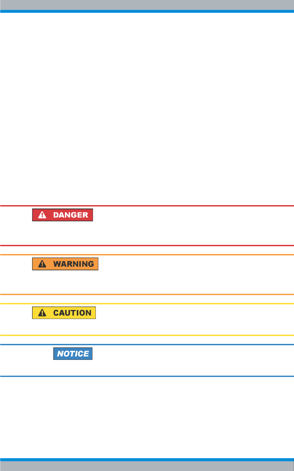
In the following, different examples of transmitters with maximum configuration are dis-
played.
Fig. 3-1: TMU 9 – Multi Tx single drive with six transmitters.
Design and Function R&S TMU9
Transmitter System R&S TMU9
R&S® TMU9
25System Manual 2600.5423.02 ─ 01
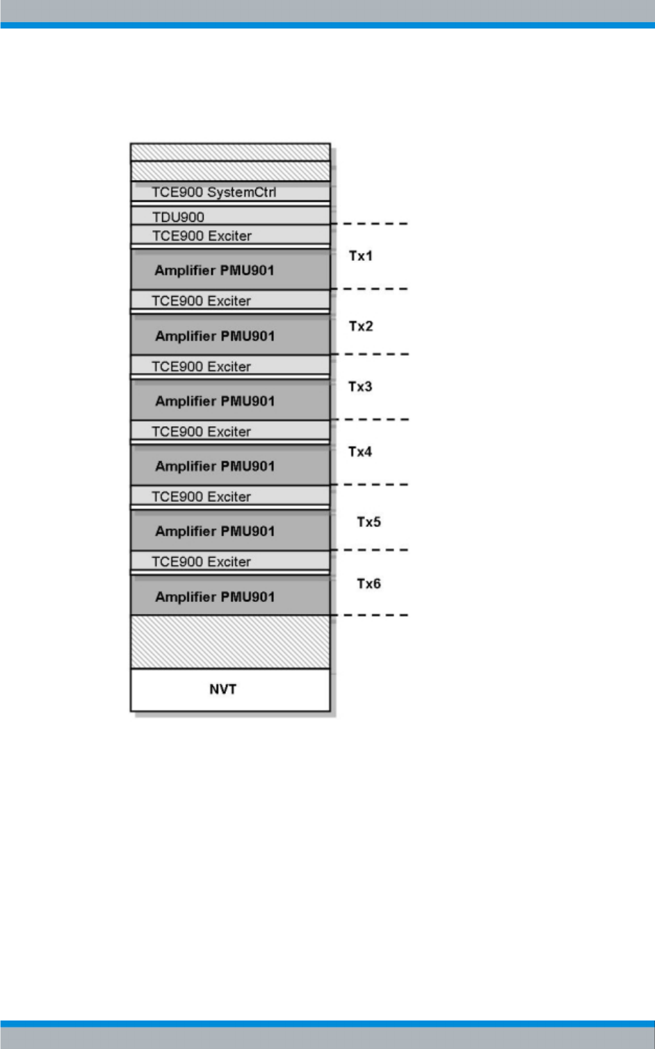
Fig. 3-2: TMU9 – Multi Tx dual drive with five transmitters.
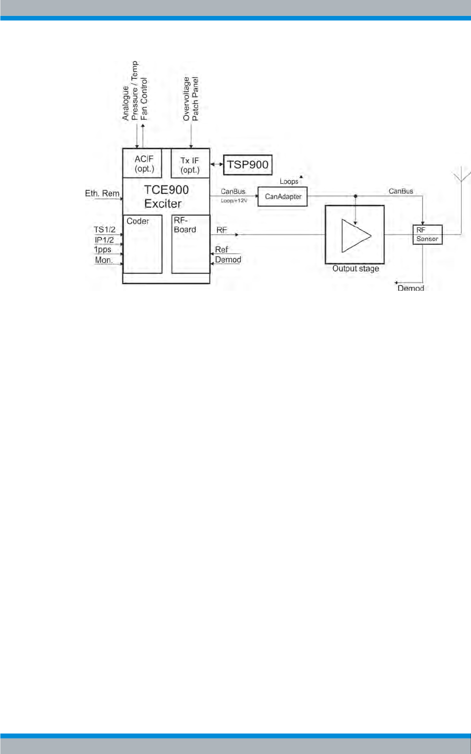
3.1.3 Redundancy Concepts
Single transmitter (single drive)
This simplest variant for medium-power transmitters consists of an exciter (R&S TCE900-
Exciter) and an output stage. The redundancy in this transmitter type is exclusively in the
output stage, which can consist of n amplifiers (n = max. of 5 per rack).
Design and Function R&S TMU9
Transmitter System R&S TMU9
R&S® TMU9
26System Manual 2600.5423.02 ─ 01
Fig. 3-3: Single Drive - block diagram.
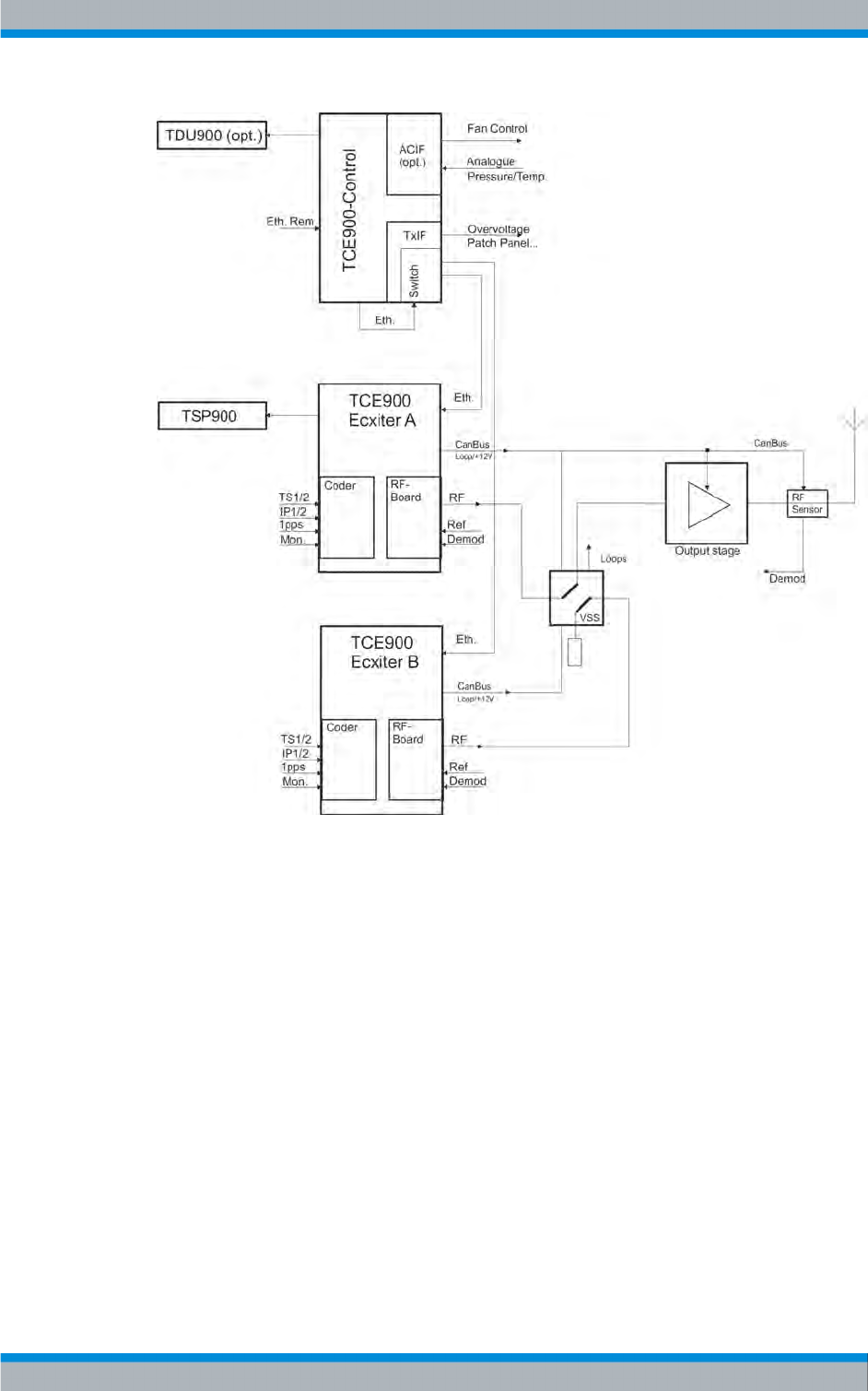
Dual drive
This variant of a dual-drive transmitter consists of a transmitter control unit (R&S TCE900-
SystemControl), two exciters (R&S TCE900 exciter), an exciter switch, and an output
stage. If one of the exciters fails, the transmitter control unit uses the exciter switch auto-
matic to switch to the second exciter via moving the exciter switch.
The redundancy properties of the output stage correspond to those of a single transmitter.
One rack from the R&S TMU9 series offers space for a maximum of five transmitters as
a dual-drive solution.
Design and Function R&S TMU9
Transmitter System R&S TMU9
R&S® TMU9
27System Manual 2600.5423.02 ─ 01
Fig. 3-4: Dual Drive - block diagram
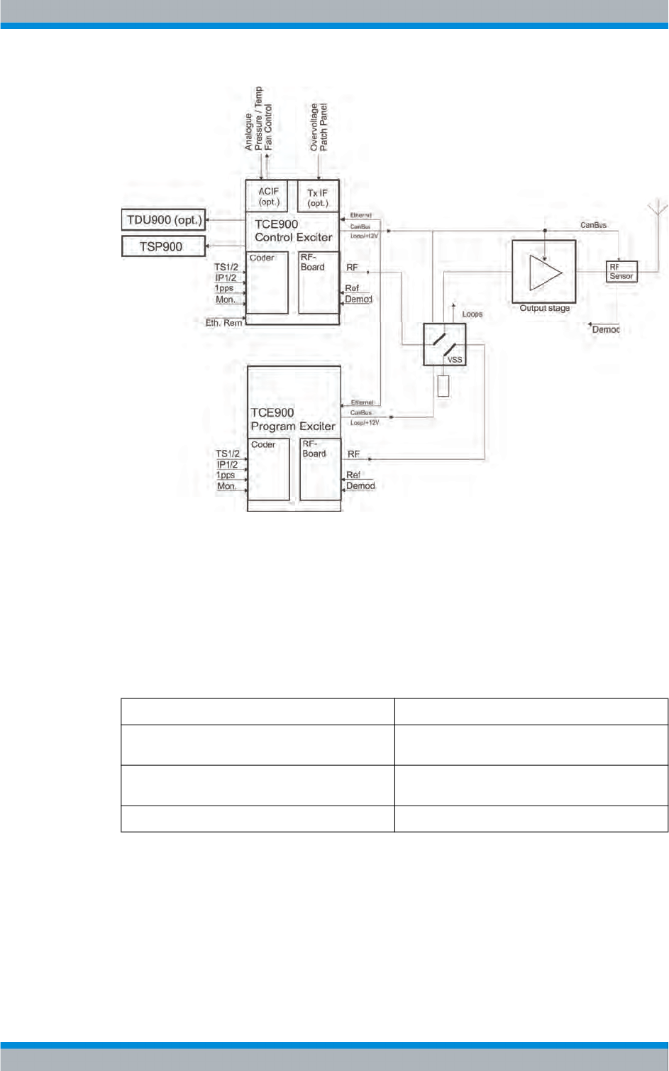
Backup drive
This variant of a dual-drive transmitter consists of 2 exciters (R&S TCE900 exciter) with
various functions, an exciter switch, and an output stage. In contrast to the dual-drive
solution, with the backup drive a TCE900-System Control is not necessary. By default,
the program exciter (R&S TCE900 program exciter) is connected to the output stage and
supplies the modulation signal. The control exciter (R&S TCE900 control exciter) moni-
tors the program exciter and switches to the output stage if the program exciter fails. A
rack of the R&S TMU9 series offers space for a maximum of 5 transmitters as a backup
drive solution.
Design and Function R&S TMU9
Transmitter System R&S TMU9
R&S® TMU9
28System Manual 2600.5423.02 ─ 01
Fig. 3-5: Backup drive – block diagram.
3.1.4 Applications
MultiTx transmitters can be combined with any kind of redundancy. Consequently, how-
ever, the possible maximum number of transmitters in a rack decreases.
Theoretically possible structure in the rack:
Transmitter type per rack
Single transmitter 6 single transmitters (with one amplifier for each
transmitter)
Dual drive 5 transmitters with dual drive (with one amplifier for
each transmitter)
N+1 4 + 1 system (with one amplifier for each transmitter)
A rack of the R&S TMU9 series offers space for a maximum of 6 single transmitters, each
with one amplifier.
Transmitter constellation with MultiTx systems
The MultiTx application presupposes a combination of similar transmitters. In this case,
there are different options:
MultiTx transmitter with 1 amplifier / Tx
Design and Function R&S TMU9
Transmitter System R&S TMU9
R&S® TMU9
29System Manual 2600.5423.02 ─ 01
Up to 6 single transmitters can be integrated for each rack. Up to 5 dual drives can be
installed for each rack.
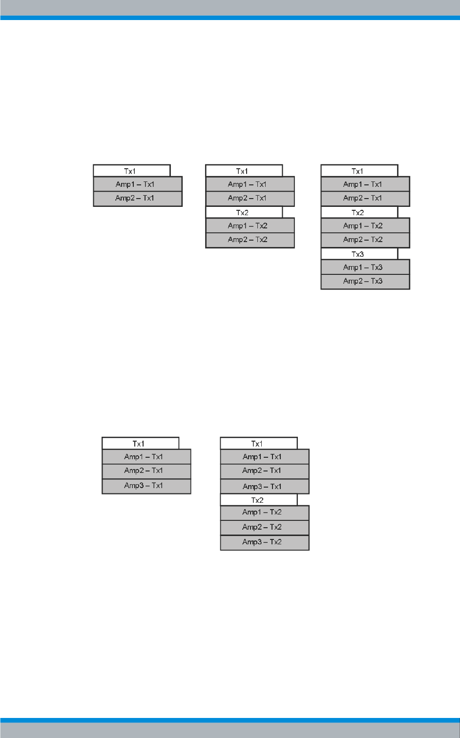
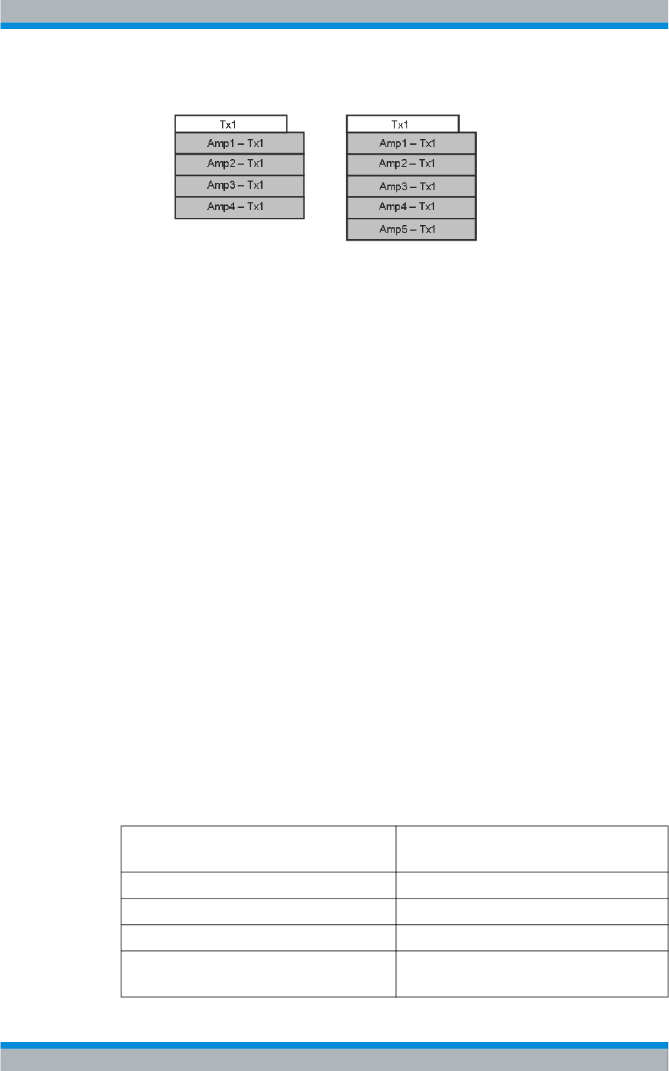
MultiTx transmitters each with 2 amplifiers / Tx
Up to 3 single transmitters can be integrated for each rack. Up to 3 dual drives can be
installed for each rack.
Fig. 3-6: MultiTx transmitters, each with 2 amplifiers per transmitter.
Tx = Transmitters 1 to 3
Amp x = Amplifiers 1 to 2 per transmitter
MultiTx transmitters each with 3 amplifiers / Tx
Up to 2 single transmitters can be integrated for each rack. Up to 2 dual drives can be
installed for each rack.
Fig. 3-7: MultiTx transmitters, each with 3 amplifiers per transmitter.
Tx = Transmitters 1 to 2
Amp x = Amplifiers 1 to 3 per transmitter
MultiTx transmitters each with 4 or 5 amplifiers / Tx
A single drive transmitter, dual drive transmitter system, or backup drive transmitter sys-
tem can be installed.
Design and Function R&S TMU9
Transmitter System R&S TMU9
R&S® TMU9
30System Manual 2600.5423.02 ─ 01
Fig. 3-8: MultiTx transmitters each with 4 or 5 amplifiers per transmitter.
Tx = Transmitter 1
Amp x = Amplifiers 1 to 4 or 5 per transmitter
3.1.5 Overview of Modules and Devices
3.1.5.1 Mains Distribution Unit
Design
The R&S ZR900Z10 mains distribution unit is designed as a 19" rackmount and serves
to provide power and safeguard various devices such as amplifiers, transmitter control
units, etc.
The mains distribution unit consists of the following modules or components:
●Main switch Q1
●Circuit breakers F1 to F20
●Overvoltage protection A101
●Network access terminal X1
●4 terminals for auxiliary contacts (optional)
●Network output terminal X2
Characteristics
The variant of the ZR900Z10 mains distribution unit implemented until now is Var. 21.
Characteristics Var. 21
(2600.1370.21)
Supply voltage 230 V: L1, L2, or L3 to N
Main switch Q1 designed for max. 63 A
Protective contacts (optional) designed for max. 10 A
Protection Single-pole circuit breakers F1 to F6: 20 A
Single-pole circuit breakers F7 to F20: 6 A
Design and Function R&S TMU9

Transmitter System R&S TMU9
R&S® TMU9
31System Manual 2600.5423.02 ─ 01
Characteristics Var. 21
(2600.1370.21)
Overvoltage protection A101 One overvoltage arrester for each of L1, L2, L3, and
N
Connectors for max. 20 devices
Function
See circuit diagram 2600.1370.01 S.
The supply voltage is routed to network access terminal X1 with three phases (L1, L2,
L3, N). As an option, the two-pin switches can also be connected with the auxiliary con-
tacts (each 1 phase and N). The individual phases are routed from X1 to main switch Q1
via cable W1E. Q1 enables the total load to be switched on and off at all poles.
The voltage is routed with three phases from Q1 to overvoltage protection A101, which
contains one overvoltage arrester for each phase. Any overvoltage is diverted via W1T
and X1.PE to PE.
Via W1T, the individual phases L1, L2, and L3 are each routed to circuit breakers F1 to
F20, so that 230 V are present there with respect to N. The outputs of the circuit breakers
are connected to output terminal strip X2 via cables W2A, W3A, and W3B. A max. of 20
loads are connected to X2.
Thus each load is protected against overcurrent by a circuit breaker. Circuit breakers F1
to F6 trigger at 20 A and serve to protect the amplifiers. Circuit breakers F7 to F20 trigger
at 6 A and serve to protect the TCEs, the fans of an exhaust kit (optional), or any customer
instruments.
Standby power supply (with amplifiers)
If an optional standby power supply is installed for an amplifier, the main and standby
power supplies operate in parallel, each at half power. If one of the two power supplies
drops out, the functional one operates as the power supply at full power.
Amplifiers not including a standby power supply are connected to L, N, and PE (network
output terminal X2) using a 3-wire cable. When using a standby power supply, a 5-wire
cable is used to connect to L1, L2, N1, N2, and PL1, since now the main and standby
power supplies are protected by a separate circuit breaker.
3.1.5.2 Transmitter Control Unit
The transmitter control unit contains the following components:
●R&S TCE900 SysCtrl
The transmitter control unit is responsible for both internal and external communications,
including all control functions.
Design and Function R&S TMU9
Transmitter System R&S TMU9
R&S® TMU9
32System Manual 2600.5423.02 ─ 01
The current status of the transmitter system can optionally be shown on a straightforward
color display via the R&S TDU900.
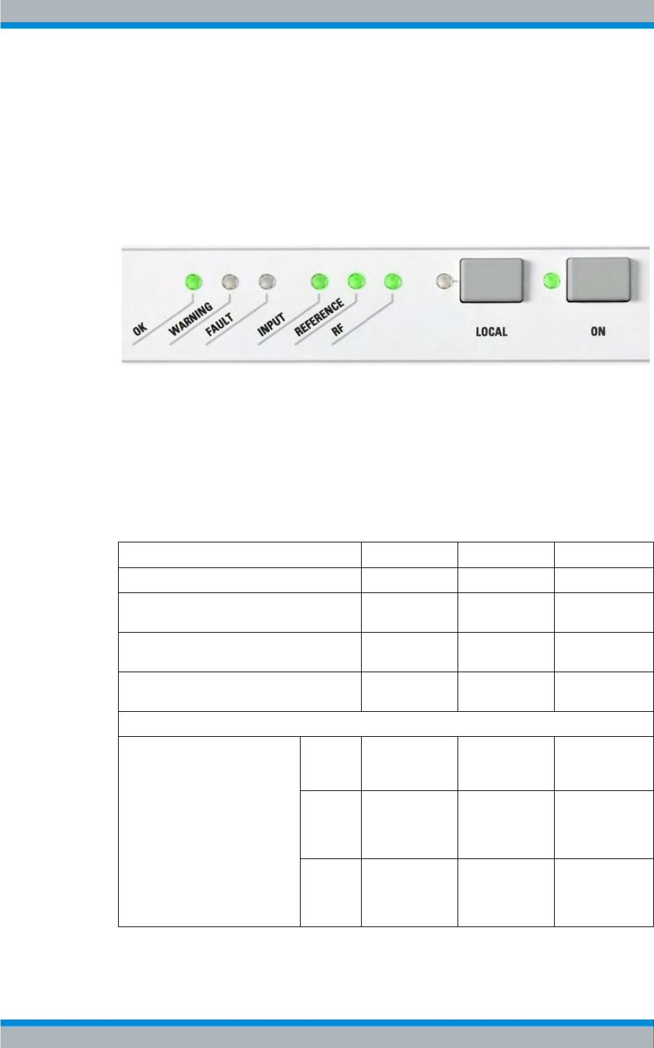
3.1.5.3 TSP900 (Transmitter Status Panel)
The TSP900 allows local operation of a transmitter. One TSP900 is allocated to each
transmitter (single drive, dual drive, backup drive) and is fastened to the front panel of
the respective transmitter.
Fig. 3-9: TSP900 (Transmitter Status Panel)
For single drive, dual drive, and backup drive transmitters with optional TDU900, the
TSP900 (keys and LEDs) are active in parallel with the TDU900.
For N+1 and MultiTx transmitters, each individual transmitter has a separate TSP900,
which enables local operation of the single transmitter.
Meaning of the LEDs
Single drive Backup drive Dual drive
OK (green) Transmitter all
OK
Transmitter all
OK
Transmitter all OK
Warning (orange) Warning for trans-
mitter
Warning for
transmitter
Warning for trans-
mitter
Fault (red) Fault for transmit-
ter
Fault for transmit-
ter
Fault for transmit-
ter
Input OK Sum input status
of the exciter is
OK
Sum input status
of the active
exciter is OK [2]
Sum input status
of the active
exciter is OK [2]
W Sum input status
of the exciter has
a Warning
Sum input status
of the active
exciter has a
Warning [2]
Sum input status
of the active
exciter has a
Warning [2]
F Sum input status
of the exciter has
a Fail
Sum input status
of the active
exciter has a Fail
[2]
Sum input status
of the active
exciter has a Fail
[2]
Design and Function R&S TMU9

Transmitter System R&S TMU9
R&S® TMU9
33System Manual 2600.5423.02 ─ 01
Reference OK Sum reference of
the exciter is OK
Sum reference of
the active exciter
is OK [3]
Sum reference of
the active exciter
is OK [3]
W Sum reference of
the exciter has a
Warning
Sum reference of
the active exciter
has a Warning [3]
Sum reference of
the active exciter
has a Warning [3]
F Sum reference of
the exciter has a
Fail
Sum reference of
the active exciter
has a Fail [3]
Sum reference of
the active exciter
has a Fail [3]
Off Reference signal
(10 MHz/ PPS/
GPS…) is not
present and is not
required, since
frequency regula-
tion source is set
to "Manual"
Reference signal
(10 MHz/ PPS/
GPS…) for the
active exciter is
not present and is
not required,
since frequency
regulation source
is set to "Manual"
Reference signal
(10 MHz/ PPS/
GPS…) for the
active exciter is
not present and is
not required, since
frequency regula-
tion source is set
to "Manual"
RF OK Transmitter RF
OK
Transmitter RF
OK
Transmitter RF
OK
W Transmitter RF
Warning
Transmitter RF
Warning
Transmitter RF
Warning
FTransmitter RF
Fail [1]
Transmitter RF
Fail [1]
Transmitter RF
Fail [1]
Off Transmitter pro-
gram off
Transmitter pro-
gram off
Transmitter pro-
gram off
Local Transmitter
Local/Remote
LED shows the
Local status (yel-
low)
Transmitter
Local/Remote
(applies for pro-
gram and control
exciter)
LED shows the
Local status (yel-
low)
Transmitter Local/
Remote (applies
for Tx control,
exciter A and
exciter B)
LED shows the
Local status (yel-
low)
On Transmitter On
(ON/OFF com-
mand accepted
by the transmit-
ter)
Transmitter On
(ON/OFF com-
mand accepted
by the transmit-
ter)
Transmitter On
(ON/OFF com-
mand accepted by
the transmitter)
[1] Special case: Saved RF Fail for (switched over and) switched off transmitter
[2] If an exciter switchover – called up by an incorrect input feed – already took place, the
faulty input feed to the switched-over exciter cannot be identified by the input LED.
Instead, only a transmitter sum warning is displayed for the exciter automatic switchover
function.
[3] If an exciter switchover – called up by an incorrect reference feed – already took place,
the faulty reference feed to the switched-over exciter cannot be identified by the REF-
Design and Function R&S TMU9

Transmitter System R&S TMU9
R&S® TMU9
34System Manual 2600.5423.02 ─ 01
ERENCE LED. Instead, only a transmitter sum warning is displayed for the exciter auto-
matic switchover function.
3.1.5.4 Exciter and System Components
The exciter consists of the following components:
●Exciter
●Exciter switch (for exciter standby only)
●CAN bus adapter (for single drive only)
●TS distributor (optional)
Exciter
The R&S TCE900 exciter performs all signal processing from the audio/video input signal
or transport stream signal up to an RF output signal that complies with the relevant
standards.
For additional information, refer to the TCE900 instrument manual.
Exciter Switch
With dual-drive transmitters (dual drive), the exciter switch switches to the standby exciter
in the following cases:
●If the main exciter malfunctions
●If there is a manual switchover via the R&S TCE900 SysCtrl
The exciter switch is controlled by the exciter switch automatic, which is operating on
both TCE900-Exciters redundant,
CAN Bus Adapter
The CAN adapter is required for communication between the individual system compo-
nents (output stage and CAN bus-capable test point) and the transmitter control unit (for
single drive only).
TS Distributor
The transport stream (TS) distributor distributes the input signal to the respective exciter
(for dual drive only).
3.1.5.5 Output Stage Unit
The air-cooled R&S PMU901 amplifier is a broadband unit that operates as a power
amplifier in the frequency range from 470 MHz to 862 MHz with the following TV stand-
ards:
●Digital (DTV) standards: DVB-T/H, DVB-T2, ATSC, ATSC Mobile, ISDBTB
●Analog (ATV) standards: ATVc (combined) B/G, D/K, K1, I, I1
Design and Function R&S TMU9

Transmitter System R&S TMU9
R&S® TMU9
35System Manual 2600.5423.02 ─ 01
For additional information, refer to chapter 5.1, "Design and Function R&S PMU901",
on page 73.
3.1.5.6 OSKAR Coupler Module
The acronym OSKAR stands for harmonics filter, splitter, coupler, absorber, and direc-
tional coupler (Oberwellenfilter, Splitter, Koppler, Absorber, Richtkoppler).
The OSKAR coupler module is a complete functional unit with the following functions:
●RF signal distribution (splitter)
●RF signal combination (coupler)
●Cooling system of the coupler and the load compensation resistors by arranging the
coupler in the exhaust air flow of the amplifier
●Integrated harmonics filter for either band IV or band V
●Three directional coupler test points as separate sensors:
– CAN bus-capable test point (forward/reflected power), frequency response-com-
pensated
– ADE test point (forward/reflected power)
– Free test point (forward/reflected power, optional)
The directivity of the test points is at ≈ 34 dB.
Depending on how many amplifier output signals are to be combined, the following four
different coupler versions can be used.
●2-way coupler/splitter for an output stage with 2 power amplifiers
●3-way coupler/splitter for an output stage with 3 power amplifiers
●4-way coupler/splitter for an output stage with 4 power amplifiers
●5-way coupler/splitter for an output stage with 5 power amplifiers
3.1.5.7 External Directional Coupler (GD901/902)
An external directional coupler can be used to measure the transmitter output power for
transmitters with an amplifier.
You can select either the GD901 or the GD902 with one or two measurement connections
for the forward and reflected power (connection to main line 7-16).
3.1.5.8 Bandpass Filter
A UHF channel bandpass filter is provided downstream of the amplifiers to reduce out-
of-band interference. In the signal path, the bandpass filter is located before the har-
monics filter.
Design and Function R&S TMU9

Transmitter System R&S TMU9
R&S® TMU9
36System Manual 2600.5423.02 ─ 01
3.1.5.9 RF Connector
The RF connector (EIA flange) is on the transmitter roof (alternatively, it can also be
located at the base of the transmitter). The size (diameter) of the RF connector is 1 5/8".
3.1.5.10 Parallel Remote Control Interface
The parallel remote control interface is used to operate the transmitter from a remote
location via parallel wire connections (not a computer interface). You can use a remote
operator position to issue commands (ON, OFF, etc.) or to receive messages from the
transmitter, such as status messages (TRANSMITTER ON).
Custom Interfaces
No. Designation Type Connection Remarks
X101A
X101B
Commands to
transmitter
25-pin D-Sub
socket
Command line The module has
optocoupler inputs
floating with respect
to 0 V. 0 V floating
is applied to pin 24
and 25. (as per
command line)
Commands 1 to 16
to X101A pin 1 to 16
Commands 17 to 32
to X101B pin 1 to 16
X201A
X201B
Messages from
transmitter
25-pin D-Sub plug Relay outputs The module has
normally-open (NO)
contacts or double-
throw (DT) contacts
for messages.
Messages 1 to 9
and 76 are applied
to X201A.
Messages 10 to 18
and 77 are applied
to X201B.
NO contacts are
available for mes-
sage 1 to 6 and 10
to 15; all others
have DT contacts.
Design and Function R&S TMU9

Transmitter System R&S TMU9
R&S® TMU9
37System Manual 2600.5423.02 ─ 01
No. Designation Type Connection Remarks
X203A
X203B
Messages from
transmitter
25-pin D-Sub plug Relay outputs The module has
normally-open (NO)
contacts or double-
throw (DT) contacts
for messages.
Messages 19 to 24
and 78 are applied
to X203A.
Messages 28 to 33
and 79 are applied
to X203B.
NO contacts are
available for mes-
sage 19 to 24 and
28 to 33; all others
have DT contacts.
X205A
X205B
Messages 25-pin D-Sub plug Relay outputs The module has
normally-open (NO)
contacts or double-
throw (DT) contacts
for messages.
Messages 37 to 46
are applied to
X205A.
Messages 47 to 56
are applied to
X205B.
NO contacts are
available for mes-
sage 37 to 42 and
47 to 52; all others
have DT contacts.
X207A X207B Messages 25-pin D-Sub plug Relay outputs The module has
normally-open (NO)
contacts or double-
throw (DT) contacts
for messages.
Messages 57 to 66
are applied to
X207A.
Messages 67 to 80
are applied to
X205B.
NO contacts are
available for mes-
sage 57 to 66 and
67 to 72; all others
have DT contacts.
Connectors for Connecting Remote Control Equipment
Special "D-Sub tandem connectors" are used. Possible designations for an X201 con-
nector are X201A and X201B.
Design and Function R&S TMU9

Transmitter System R&S TMU9
R&S® TMU9
38System Manual 2600.5423.02 ─ 01
The designation of the connector pin indicates the respective half of the tandem con-
nector.
Example: Command 1 is applied to connector X101, pin 1A. The command can be input
at connector pin 1 of connector 101A.
Command Inputs
All command inputs are operated via optocouplers with a floating supply voltage that is
generated on the module. A command input becomes active by means of a connection
to the common command line. Both continuous signals and pulse signals are permitted.
With pulse signals, a minimum pulse length of 100 ms must be ensured. With continuous
operation, the signal which became active last is rejected in the case of mutually exclusive
signals.
Example: The TRANSMITTER ON command is valid and the TRANSMITTER OFF com-
mand is issued. The TRANSMITTER OFF command stays invalid for as long as the first
ON command is active. The command inputs are distributed between two 25-pin D-Sub
sockets (X101A, X101B).
Message Outputs
All message outputs are implemented by means of floating relay contacts. A message is
valid when the contact is in its closed state. Normally-open (NO) contacts and, to a limited
extent, normally-closed (NC) contacts are available for this purpose. Relays with bistable
switching characteristics are reserved for the local/remote messages of the correspond-
ing function groups.
The module can be used universally for FM, DAB, and TV transmitters. It contains the
consecutively numbered commands COMMAND 1 to COMMAND 32 and the consec-
utively numbered message outputs MESSAGE 1 to MESSAGE 80.
Assignment to Transmitter Functions
The messages or commands are assigned to the transmitter functions according to the
used configuration via a routing program stored in the higher-level control unit. During
the configuration phase, this program assigns the command inputs and message outputs
their logical meaning according to the functional use of the module.
Communication between Remote Control Interface and Transmitter
Data is exchanged with the R&S TCE900 SysCtrl unit via an internal CAN bus. The
transmitter control unit also provides the operating voltage for the remote control inter-
face.
CAN Bus
The remote control interface has an internal 9-pin CAN bus D-Sub plug X1 and a 9-pin
CAN bus D-Sub socket X11. The module receives its power supply (+12V) via the CAN
bus plug X1.
Design and Function R&S TMU9
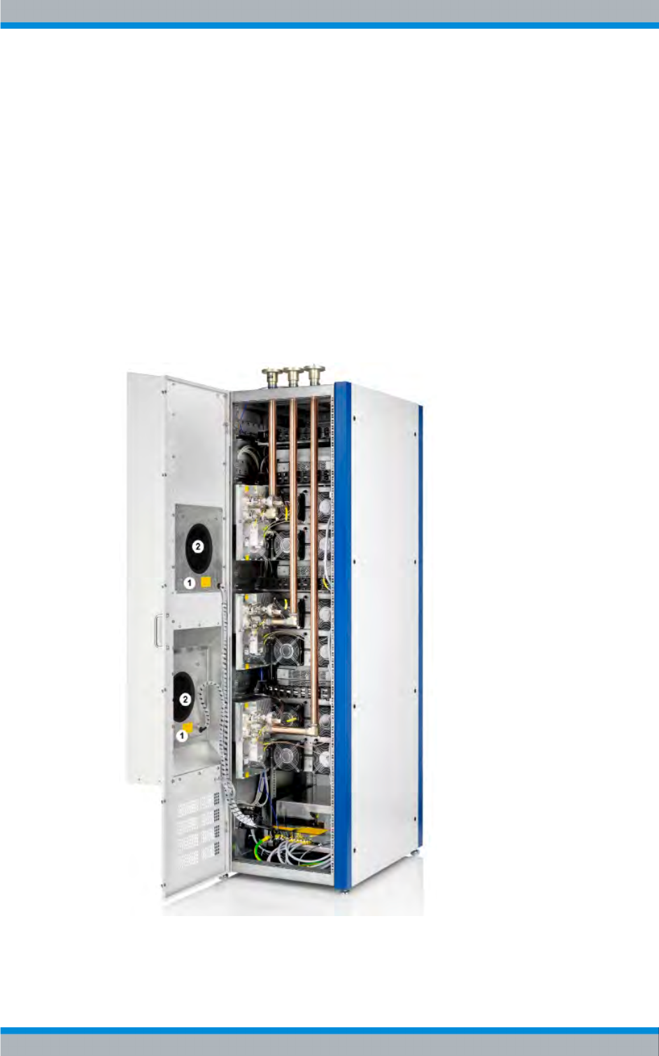
Transmitter System R&S TMU9
R&S® TMU9
39System Manual 2600.5423.02 ─ 01
Single Transmitter and Standby System
In a single transmitter, the remote control interface is directly connected to the TCE900
SysCtrl via the CAN bus plug X1. The X11 socket remains free.
In standby systems, the CAN bus is connected to further n+1 modules via X11.
3.1.5.11 Exhaust Kit (optional)
The exhaust kit allows the transmitter to be connected to a central ventillation system at
the transmitter station or for the hot air from the transmitter to be vented directly outside.
Two differential pressure sensors (1) are used to measure the pressure inside the frame
enclosure with reference to the outside air pressure. Through the ACIF of the TCF, the
RPM of the two fans (2) are regulated with the aim of maintaining normal air pressure
within the enclosed frame.
Fig. 3-10: Mutli Tx transmitter with exhaust kit
1 = Differential pressure sensors
2 = Fans
Design and Function R&S TMU9

Transmitter System R&S TMU9
R&S® TMU9
40System Manual 2600.5423.02 ─ 01
This option cannot be ordered separately and subsequently installed in the transmitter
system, since some modules or components have to be preassembled at the factory.
The cooling system consists of the following modules or components:
●Exhaust kit TM9-C1
– Fans E1, E2
– Differential pressure sensors S1, S2
–Temperature sensor B2
– Exhaust air transfer duct
●Air cooling interface (ACIF) (option to the TCE900 TxControl transmitter control unit)
The air cooling interface (ACIF) is used to establish the connection from the TM9-C1
exhaust kit to the TCE900 SysCtrl unit. The ACIF serves in part to control speed and
monitor the fans and, where appropriate, to send error messages to the TCE900 SysCtrl.
Pressure sensors S1 and S2 measure the pressure inside and outside of the rack. Thus,
a pressure-neutral environment can be configured in the rack. Temperature sensor B2
measures the exhaust air temperature in the vicinity of the exhaust air transfer duct.
Mains distribution unit ZR900Z10 protects fan E1 via circuit breaker F7 and fan E2 via
circuit breaker F8.
3.1.6 Performance Features
Efficiency
The efficiency of a transmitter is correctable. This readjustment of the transmitter effi-
ciency is done by modifying the DC supply of the power amplifier.
To get an idea for transmitters that are not operated at the nominal power, the following
estimation is permitted.
Unew=√(Pnew/Pnom)*Unom
Here, a linearity precorrection found at nominal power does not yet have to be adapted.
Uninterruptible power supply
To bridge extended power supply faults, the control and signal processing components
present in the transmitter are equipped with a separate supply. The following options are
available for an uninterruptible power supply:
●The "external UPS feed" option
The external supply can be switched off via the main switch and supplies the trans-
mitter control unit components and the exciters. Alternatively, one or more UPS devi-
ces can be installed in the option section of the rack. The UPS devices are 19" rack-
mounts with 1 HU.
●The "internal UPS" option
The "internal UPS" option uses a UPS (additional purchase part) as a 19" instrument
rackmount with 1 HU. The 3 free rack units (option section) are intended as the
Design and Function R&S TMU9

Transmitter System R&S TMU9
R&S® TMU9
41System Manual 2600.5423.02 ─ 01
defined installation location. This means it is not possible to equip all exciters and the
transmitter control unit with an independent UPS for MultiTx in the full configuration.
●The "redundant voltage supply for the transmitter control unit (TCE900 CTRL)" option
The transmitter control unit (TCE900 CTRL) has an optional "external supply" rack-
mount for an "+12 V external" supply.
Emergency mode
If the transmitter control unit has failed or communication with the transmitter components
has been interrupted, the system is in emergency mode.
This means the last operating states in all system components are saved to nonvolatile
memory, with exception of the power amplifiers, for which the operation settings are
saved only until the next restart. When restarted, the amplifiers are re-commanded by
the active exciter.
The system components maintain this operating state until other states are commanded
by a new/repaired/replaced transmitter control unit.
3.1.7 Power Display and Reflection Monitor
Displays
The displays of the transmitter show the forward and reflected power of the transmitter
output. The forward and reflected power is displayed with an accuracy better than ± 5 %
of the nominal value.
RF forward monitoring and messages
For nominal power up until the warning level, the transmitter sends the messages RF ON
and RF OK.
If the configurable warning threshold (0 dB to -20 dB) is undershot, the transmitter sends
the RF ON message and an additional warning message (RF WARNING). The RF OK
message is canceled.
If the configurable fault threshold (0 dB to -20 dB) is undershot, the transmitter cancels
the RF ON message right away and issues an RF fault (RF FAIL) after a configurable
waiting period (1 s to 20 s).
Reflection warning
A warning threshold is set to generate a reflection warning.
The warning threshold lies between -18 dB and -28 dB and is the return loss in dB.
Reflection fault
The transmitter is switched off when the return loss is –17 dB to -14 dB (configurable)
(corresponds to 1/50 to 1/20 of the forward power). It can be switched off by blocking the
RF (RF carrier loop).
Design and Function R&S TMU9

Transmitter System R&S TMU9
R&S® TMU9
42System Manual 2600.5423.02 ─ 01
Within one minute after it has been switched off the first time, three attempts at switching
it back on will be made. If there is still reflection after the last attempt to switch it on, the
transmitter is permanently switched off (Output Stage will be switched off) and a "Reflec-
tion" fault message is generated.
3.1.8 Specifications
3.1.8.1 Transmitter System, General – DTV
General
DVB-T/-H DVB-T2 ISDB-T ATSC
Frequency range 470 MHz to 862 MHz
UHF band IV/V:(step size 1 Hz)
Frequency range Doh-
erty
470 MHz to 790 MHz
Channel bandwidth 5/6/7/8 MHz 1.7/5/6/7/8 MHz 6/7/8MHz 6 MHz
Standards EN 300744
EN 302304 (opt.)
EN 302755 ARIB STD-B31
ABNT NBR 15601
FCC Doc. A/53
SFN / DTx function TS 101191 ARIB STD-B31
ABNT NBR 15601
EMC EN 302296
EN 301489-1 / -14
With channel bandpass filter
ARIB STD-B31
ABNT NBR 15601 Part 1
Max. installation alti-
tude
2000 m (sea level); up to 3000 m on request
Operating temperature
(operation room)
+1 °C to +45 °C
Maximum relative
humidity
95 % non-condensing (interior)
Environmental class ETSI EN 300-019-1-3
Interior, in acc. with 3.2, with limited temperature range, non-condensing
Voltage supply 3W+N+PE (Y)
230 V AC/400 V AC ±15 %
AC supply frequency 47 Hz to 63 Hz
Power factor per phase ≥ 0.95
Circuit feedback EN 61000-3-2 fulfilled for transmitters with ≤ 3 amplifiers
EN 61000-3-12 fulfilled for transmitters with ≥ 4 amplifiers
Design and Function R&S TMU9

Transmitter System R&S TMU9
R&S® TMU9
43System Manual 2600.5423.02 ─ 01
DVB-T/-H DVB-T2 ISDB-T ATSC
Immunity --> to fast
transients and bursts
(in acc. with EN
61000-4-4)
< 2kV (mains)
< 1 kV (signals)
Immunity to surges -->
(in accordance with EN
61000-4-5)
< 1kV (symmetric)
< 2kV (non-symmetric)
Noise level Interior: < 60 dBA
Permitted VSWR s ≤ 1.33
at the transmitter level optionally at s > 1:1.33 shutoff (standard) or s > 1:1.45 (configurable)
RF connector EIA 1 5/8"
Inputs
DVB-T/-H DVB-T2 ISDB-T ATSC
Input signals ASI ASI
TS over IP
ASI ASI
SMTPE310M
Data rate 3 Mbps to 30 Mbps 3 Mbps to 50 Mbps 32,507937 Mbps 19.39 Mbps
inputs 2 x ASI (HP/LP)
BNC 75 Ω
2 x ASI
BNC 75 Ω
2 x ASI
BNC 75Ω
2 x SMPTE310 or
2 x ASI
BNC 75 Ω
RJ-45, TCP/IP
Modulator interface - - - T2-MI
ETSI TS 102773
- - -
Reference frequency 10 MHz; 0.1 to 5 Vpp or TTL, BNC 50 Ω
Reference pulse 1 pps, TTL, BNC 50 Ω
Monitoring Current data rate, input signal present, TS synchronization present,
Packet length 204 byte/188 byte Fixed packet length
(188 byte)
Generic cont. stream >
64 kbit
Generic fixed packe-
tized streams (<
64 kbit)
Generic encapsulated
streams (TS 102606)
High efficiency mode
204/188 Byte 207 byte/187 byte
Modulation modes QPSK,
16QAM,
64QAM
QPSK,
16QAM,
64QAM,
256QAM
DQPSK
QPSK
16 QAM
64 QAM
8 VSB
Design and Function R&S TMU9

Transmitter System R&S TMU9
R&S® TMU9
44System Manual 2600.5423.02 ─ 01
DVB-T/-H DVB-T2 ISDB-T ATSC
IFFT modes
(bandwidth specifica-
tions for 8 MHz chan-
nel)
2k, 8k
opt. 4k for DVB-H
bandwidth 7.61 MHz
1k, 2k, 4k, 8k, 16k, 32k
bandwidth 7.61 MHz
Mode 1 2k
Mode 2 4k
Mode 3 8k
- - -
Extended carrier mode - - - 8k, 16k, 32k
bandwidth 7.77 MHz
- - -
Symbol period 224 μs (2k)
448 μs (4k)
896 μs (8k)
112 μs (1k)
224 μs (2k)
448 μs (4k)
896 μs (8k)
1792 μs (16k)
3584 μs (32k)
252μs (2k)
504μs (4k)
1008μμs (8k)
- - -
Guard interval 1/4, 1/8, 1/16, 1/32 1/4, 1/8, 1/16, 1/32,
19/128, 19/256, 1/128
1/4, 1/8, 1/16, 1/32 - - -
Code rate 1/2, 2/3, 3/4, 5/6 ,7/8 1/2, 3/5, 2/3, 3/4, 4/5,
5/6
1/2, 2/3, 3/4, 5/6 ,7/8 - - -
Trellis coding - - - - - - - - - 2/3
Hierarchical coding supported - - - - - - - - -
PAPR - - - Yes - - - - - -
Rot. constellation - - - Yes - - - - - -
DVB-T2 modes - - - Single PLP
Multi PLP
- - - - - -
Delay correction Max. 1000 ms, automatic and manual setting
Precorrection ADE (adaptive digital
equalization)
ADE (adaptive digital
equalization)
ADE (adaptive digital equali-
zation)
adaptive digital equali-
zation (ADE) ext. group
delay (opt.)
Quality
DVB-T/-H DVB-T2 ISDB-T ATSC
MER ≥ 33 dB at Pnom ≥ 33 dB at Pnom ≥ 33dB at Pnom ≥ 35 dB at Pnom
Frequency response < ± 0.5 dB < ± 0.5 dB < ± 0.5dB < ± 0.25 dB
Intermodulation sup-
pression
≥ 37 dB (± 12 MHz) ≥ 37 dB (± 12 MHz) ≥ 37dB (± 12MHz) ≥ 47 dB
ref. to mean power
BW 8 MHz: ± 4.2 MHz
BW 7 MHz: ± 3.7 MHz
BW 6 MHz: ± 3.2 MHz BW 6MHz: ± 3,15MHz
Spectrum mask in line with ETSI EN
302296 with channel
bandpass filter
ABNT NBR 15601
Part 1 with channel bandpass
FCC DTV emission
mask, with channel
bandpass filter
Design and Function R&S TMU9
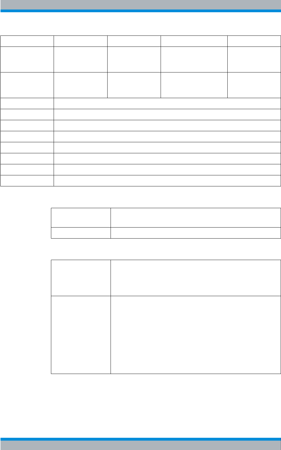
Transmitter System R&S TMU9
R&S® TMU9
45System Manual 2600.5423.02 ─ 01
DVB-T/-H DVB-T2 ISDB-T ATSC
Nonharmonics ≤ -60 dBc
Without channel band-
pass filter
≤ -60 dBc
Without channel band-
pass filter
≤ -60 dBc
Without channel band-
pass filter
Harmonics ≤ -70 dBc
Without channel band-
pass filter
≤ -60 dBc
Without channel band-
pass filter
≤ -60 dBc
Without channel band-
pass filter
Noise power density dBc / Hz
10 Hz > 70
100 Hz > 90
1 kHz > 93
10 kHz > 103
100 kHz > 112
1 MHz > 130
Frequency stability 10-7 / year
Operation
RJ-45 Operation via PC using standard web browser
(opt. network management interface for SNMP)
Parallel interface Contacts / optocoupler (opt.)
Safeguarding and monitoring
Transmitter Mains
Reflection
Temperature
RF out
Amplifier Mains
Reflection
Temperature
Overvoltage
Transistor Fail
RF Input Level
RF output level
Transistor currents
DC voltages
Design and Function R&S TMU9
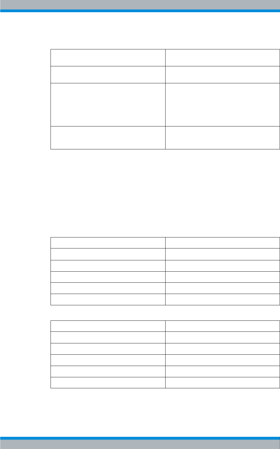
Transmitter System R&S TMU9
R&S® TMU9
46System Manual 2600.5423.02 ─ 01
Standards
ETSI EN 62015 Safety requirements for radio transmission equipment
(VDE0866 / IEC 215)
ETSI EN 60950 Safety of information technology equipment incl. elec-
trical business equipment (VDE0805 / IEC 950)
ETSI EN 301489-14 Electromagnetic compatibility for radio spectrum mat-
ters (ERM)
Electromagnetic compatibility for radio equipment
and service (EMC); Part 14: Specific conditions for
analog and digital terrestrial TV broadcasting service
transmitters
ETSI EN 302296 Electromagnetic compatibility and radio spectrum
matters (ERM); Transmitting equipment for the digital
television broadcast service, terrestrial (DVB-T)
3.1.8.2 Requirements for the Output Bandpass Filter
A channel bandpass filter is required for maintaining the brand and nonharmonics
requirements, which depend on standards.
DVB-T
The shoulder distance on the transmitter side, without filter, is presupposed to be at least
37 dB.
Table 3-1: Specification of DVB-T Channel Bandpass Filter for Non-Critical Mask
Frequency Default filter attenuation
f00.3 dB to 0.4 dB
± 3.805 MHz 0.8 dB to 1.0 dB
± 4.2 MHz ≥ 5.0 dB
± 6.0 MHz ≥ 20.0 dB
± 12 MHz ≥ 40.0 dB
Table 3-2: Specification of DVB-T Channel Bandpass Filter for Critical Mask
Frequency Default filter attenuation
f00.45 dB to 0.6 dB
± 3.805 MHz 1.0 dB to 1.5 dB
± 4.2 MHz ≥ 15.0 dB
± 6.0 MHz ≥ 27.0 dB
± 12 MHz ≥ 50.0 dB
General specifications
●VSWR: ≤ 1.22 min in the range ± 3.805 MHz
Design and Function R&S TMU9

Transmitter System R&S TMU9
R&S® TMU9
47System Manual 2600.5423.02 ─ 01
●Drift:: ≤ 2 kHz/K
●RF connector: 3 1/8" pipe connection
DVB-T2
The shoulder distance on the transmitter side, without filter, is presupposed to be at least
37 dB.
For DVB-T2, a new operating mode, "Extended carrier mode," was introduced in the
standard. This mode can be activated at FFT sizes of 8k, 16k, and 32k and leads to a
bandwidth extension of ± 80 kHz.
The throughput range with DVB-T2 is at ± 3.885 MHz, the max. impedance matching has
to be ensured in this range.
The attenuation requirements in the stopband are identical as with DVB-T.
ATSC
The shoulder distance on the transmitter side, without filter, is presupposed to be at least
37 dB.
Table 3-3: Specification of Channel Bandpass Filter for "Full Power FCC Mask"
Frequency Default filter attenuation
f0±2.69 MHz 0.3 dB to 0.4 dB
± 3.00 MHz ≥ 0.5 dB
± 3.50 MHz ≥ 3.0 dB
± 4.00 MHz ≥ 8.0 dB
± 6.00 MHz ≥ 30.0 dB
± 9.00 MHz ≥ 65.0 dB
Table 3-4: Specification of Channel Bandpass Filter for "Stringent Mask"
Frequency Default filter attenuation
f0±2.69 MHz 0.3 dB to 0.4 dB
± 3.00 MHz ≥ 0.5 dB
± 3.50 MHz ≥ 3.0 dB
± 4.00 MHz ≥ 8.0 dB
± 6.00 MHz ≥ 30.0 dB
± 9.00 MHz ≥ 30.0 dB
General specifications
●VSWR: ≤ 1.12 to 1.15
●Drift:: ≤ 2 kHz/K
Design and Function R&S TMU9
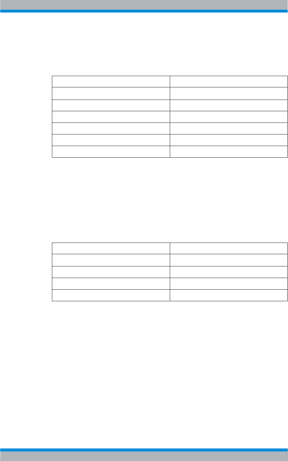
Transmitter System R&S TMU9
R&S® TMU9
48System Manual 2600.5423.02 ─ 01
ATSC (Canada)
The shoulder distance on the transmitter side, without filter, is presupposed to be at least
37 dB.
Table 3-5: Specification of Channel Bandpass Filter for "Canadian Tight Mask"
Frequency Default filter attenuation
f0±2.69 MHz 0.3 dB to 0.4 dB
± 3.00 MHz ≥ 0.5 dB
± 3.50 MHz ≥ 1 dB
± 4.00 MHz ≥ 6 dB
± 6.00 MHz ≥ 20 dB
± 9.00 MHz ≥ 30 dB
General specifications
●VSWR: ≤ 1.12 to 1.15
●Drift:: ≤ 2 kHz/K
ISDB-T (Japan)
The shoulder distance on the transmitter side, without filter, is presupposed to be at least
37 dB.
Table 3-6: Specification of Channel Bandpass Filter for "Non-Critical Mask"
Frequency Default filter attenuation
f0±2.79 MHz 0.3 dB to 0.4 dB
± 3.15 MHz ≥ 2 dB
± 4.50 MHz ≥ 20 dB
± 9.00 MHz ≥ 40 dB
General specifications
●VSWR: ≤ 1.12 to 1.22 min. in the throughput range
●Drift:: ≤ 2 kHz/K
ISDB-TB
The shoulder distance on the transmitter side, without filter, is presupposed with at least
37 dB or 42 dB.
Design and Function R&S TMU9
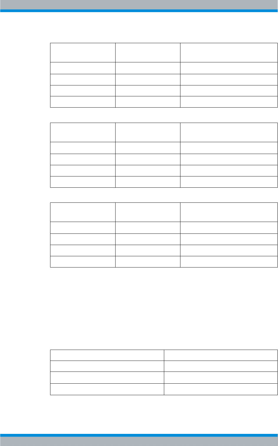
Transmitter System R&S TMU9
R&S® TMU9
49System Manual 2600.5423.02 ─ 01
Table 3-7: Specification of Channel Bandpass Filter for "Non-Critical Mask"
Frequency Default filter attenuation
(SH 37 dB)
Default filter attenuation
(SH 42 dB)
f0±2.79 MHz 0.3 dB to 0.4 dB 0.2 dB to 0.4 dB
± 3.15 MHz ≥ 2 dB 0 dB
± 4.50 MHz ≥ 20 dB ≥ 12 dB
± 9.00 MHz ≥ 40 dB ≥ 35 dB
Table 3-8: Specification of Channel Bandpass Filter for "Sub-Critical Mask"
Frequency Default filter attenuation
(SH 37 dB)
Default filter attenuation
(SH 42 dB)
f0±2.79 MHz 0.3 dB to 0.5 dB 0.3 dB to 0.4 dB
± 3.15 MHz ≥ 8 dB ≥ 3 dB
± 4.50 MHz ≥ 23 dB ≥ 18 dB
± 9.00 MHz ≥ 48 dB ≥ 40 dB
Table 3-9: Specification of Channel Bandpass Filter for "Critical Mask"
Frequency Default filter attenuation
(SH 37 dB)
Default filter attenuation
(SH 42 dB)
f0±2.79 MHz 0.4 dB to 0.6 dB 0.4 dB to 0.6 dB
± 3.15 MHz ≥ 15 dB ≥ 10 dB
± 4.50 MHz ≥ 30 dB ≥ 25 dB
± 9.00 MHz ≥ 55 dB ≥ 50 dB
General specifications
●VSWR: ≤ 1.12 to 1.22 min. in the throughput range
●Drift:: ≤ 2 kHz/K
ATV
With analog-only operation of the transmitter, a 4-circuit bandpass filter is sufficient for
achieving the standards requirements.
Table 3-10: Specification of Channel Bandpass Filter (Analog-Only Operation)
Frequency Filter attenuation
Passband < 0.2 dB (better 0.15 dB)
fB - fT>30 dB
fB + 2* fT>30 dB
Design and Function R&S TMU9
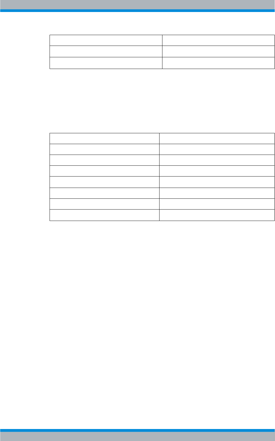
Transmitter System R&S TMU9
R&S® TMU9
50System Manual 2600.5423.02 ─ 01
Frequency Filter attenuation
fB - 2* fT≥ 24 dB
fB + 3* fT≥ 24 dB
General specifications
●VSWR: ≤ 1.06 to 1.10
●Drift:: ≤ 2 kHz/K
3.1.8.3 Parallel Remote Control Interface
Operating voltage 12 V DC
Current drain 1 A maximum
CAN interface CAN V2.0B at 1 Mbps
Number of command inputs 32
Insulation voltage 3000 Veff
Maximum external line resistance 50 Ω (referenced to common command line)
Number of message outputs 80 (of which 5 have bistable character)
Dielectric strength of contact/coil 1000 Veff
3.2 Installation R&S TMU9
3.2.1 Equipment Supplied
3.2.1.1 Integrated Transmitter Components
●TCE900 units
●System components
3.2.1.2 Transmitter Components Supplied Separately
●Amplifier
●Bandpass filter (optional, depending on transmitter configuration)
●Transmitter accessories
Installation R&S TMU9

Transmitter System R&S TMU9
R&S® TMU9
51System Manual 2600.5423.02 ─ 01
3.2.2 Overview of Transmitter Installation
The transmitter can be installed by following the basic sequence given below:
●Setting up the transmitter
–Checking the floor suitability
– Preparing openings required in the floor (only with inlets and outlets from below)
– Arranging the connections on the transmitter roof
– Setting up the transmitter rack
– Aligning the transmitter rack
– Removing the front panels
– Unpacking the components
●Installing UHF channel bandpass filter
●AC power supply
– Connecting the transmitter ground
– Connecting the power cable
– Connecting external units
●Amplifier
– Making preparations for installing the amplifiers
– Installing the amplifiers
●RF output
– Connecting the antenna
– Connecting the dummy antenna
●Connecting the modulation/reference signals
●Connecting the remote control system to the transmitter system
3.2.2.1 Required Tools
You will need the following tools to install the transmitter:
Tool Type Size
Screwdriver Torx No. 8
Screwdriver Torx No. 20
Screwdriver Phillips No. 1
Screwdriver Slotted No. 1
Screwdriver Slotted No. 3
Hexagon socket No. 5
Hexagon socket No. 6
Open-end wrench Width across flats 13 mm (2 pcs)
Open-end wrench Width across flats 10 mm
Spirit level
Installation R&S TMU9
Transmitter System R&S TMU9
R&S® TMU9
52System Manual 2600.5423.02 ─ 01
The table lists the basic tools required for installation of the transmitter rack (not for floor
openings, base frame, and so on).
3.2.3 Setting Up the Transmitter
3.2.3.1 Preparatory Work
Before setting up and installing the transmitter, you must make the following preparations:
●Checking the floor suitability
●Prepare openings required in the floor and set the screw holes in the floor for fixing
the rack (optional)
●Arranging the connections on the transmitter roof
Checking the floor suitability
Before installing the transmitter, you must check whether the floor of the building in which
the transmitter is to be operated has an adequate weight to floor area ratio.
Depending on the type of system, a transmitter rack of the THU9/TMU9 family can have
a total weight of up to 720 kg with the maximum number of rackmounts installed. A weight
to floor-area ratio of at least 1200 kg / m2 is therefore required.
The exact weight of your transmitter is given in the specifications.
The installation surface should be flat (i.e. horizontal along all axes) and measure at least
600 mm x 1100 mm to accommodate the transmitter rack.
During installation, the transmitter must be easily accessible from the front and rear. A
clearance space of at least 1.2 m is necessary in order to install all components without
difficulty.
Preparing openings required in the floor (only with inlets and outlets from below)
If cables (RF cables, control lines, etc.) are to be connected to the transmitter from below,
you must make appropriate floor openings in the building in which the transmitter is to be
operated.
Further details and dimensions can be found in the corresponding drawing in the appen-
dix "Basic documentation":
Installation R&S TMU9
Transmitter System R&S TMU9
R&S® TMU9
53System Manual 2600.5423.02 ─ 01
3.2.3.2 Setting Up the Transmitter Rack
The transmitter rack can be set up using lifting equipment (crane). Lifting lugs are
attached to the top of the rack for this purpose.
Crushing Hazard
Do not stand under suspended racks.
Risk of Falling
Take the relevant safety precautions when climbing ladders (not wobbly, suitable foot-
wear)
3.2.3.3 Aligning the Transmitter Rack
The rack must be aligned vertically and horizontally in order to prevent distortion caused
by shearing forces.
► Using the height-adjustable rack feet, align the rack such that it is vertical and hori-
zontal along all axes.
Use a water level to align the rack.
3.2.3.4 Bolting the Transmitter Rack to the Floor
If required, the transmitter rack can be screwed to the floor or a floor frame. Two 12 mm
boreholes are provided in the lower crossbeam of the transmitter rack for this purpose.
3.2.3.5 Removing the Front Panels
Before you start installing the individual units, make sure that you have easy access to
all units, connectors, and interfaces needed.
1. Using a Torx screwdriver No. 20, remove all front panels from the rack.
2. Open the rear door of the transmitter rack.
Take care not to damage the ground connections when removing and fitting the front
panels.
Installation R&S TMU9
Transmitter System R&S TMU9
R&S® TMU9
54System Manual 2600.5423.02 ─ 01
3.2.3.6 Unpacking the Components
Each transmitter component is packaged separately.
► Remove the packaging and have all equipment ready for the installation.
3.2.4 Installing the UHF Channel Bandpass Filter
An integrated bandpass filter is optionally available.
High voltage
Risk of fatal injury from touching voltages constituting a shock hazard. The transmitter
rack must be completely de-energized before the following service work is performed,
otherwise there is a risk of injury and death caused by electric shock.
Plug in the RF components up to the respective markings.
1. Unscrew the lower front panel on the transmitter (Torx screwdriver No. 20).
2. Insert the filter into the filter trough from the front of the transmitter.
3. Align the filter brackets with the fastening holes in the filter trough and screw the filter
brackets to the filter trough (hexagon socket No. 6).
4. Install the directional coupler in the correct installation direction with the connector
bracket at the filter inlet/coupler output and fasten the directional coupler by tightening
the clamps (hexagon socket No. 5).
Installation R&S TMU9
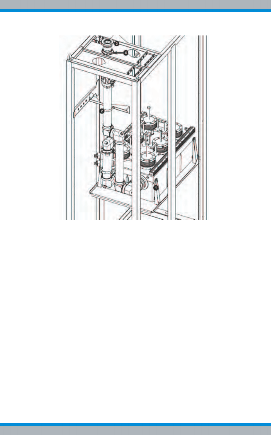
Transmitter System R&S TMU9
R&S® TMU9
55System Manual 2600.5423.02 ─ 01
1 = RF bracket on the channel bandpass filter outlet
2 = Retaining clamp of the harmonics filter
3 = EIA pipeline junction
4 = Roof mount of the directional coupler
5. Install the RF connecting pipe at the upper bracket/filter outlet and fasten the RF
connecting pipe with clamps (hexagon socket No. 5).
3.2.5 Installing the Amplifier
1. With the aid of a second person, carefully slide the amplifier into the free slot until the
automatic connectors engage. The front panel of the amplifier must be flush with the
rack uprights.
Installation R&S TMU9
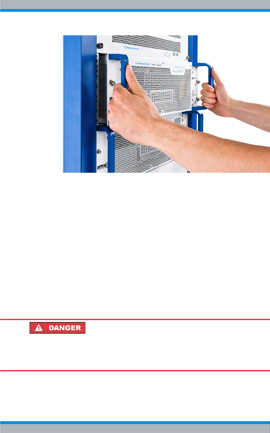
Transmitter System R&S TMU9
R&S® TMU9
56System Manual 2600.5423.02 ─ 01
Fig. 3-11: Slide the amplifier into the rack
2. Tighten the amplifier to the rack using the two screws on the front panel (Torx screw-
driver T25).
3. Switch on the amplifier via the power distribution unit in the transmitter rack (turn the
appropriate protective switch to the "I/ON" position).
If the installation was successful, the LINK LED flashes until the amplifier has been
detected by the system and is illuminated continuously if the amplifier is logged on to the
system.
3.2.6 Installing the Power Supply
3.2.6.1 General
High Voltage
Risk of fatal injury from touching dangerous voltages. To prevent injury and death from
electric shock, always make sure that the power supply is disconnected before com-
mencing any work.
Installation R&S TMU9
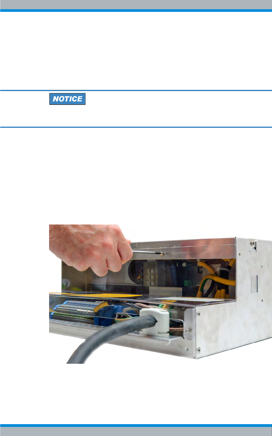
Transmitter System R&S TMU9
R&S® TMU9
57System Manual 2600.5423.02 ─ 01
The ZR900Z10 mains distribution unit is installed in the transmitter rack at the factory.
The mains distribution unit is connected to the power supply network of the transmitter
station.
3.2.6.2 Connecting the Transmitter Ground
Transmitter Ground
The rack must be connected to the station's main ground terminal.
The transmitter rack has two grounding bolts near the floor which are easily accessible
from the rear.
Connect a system ground conductor to the free grounding bolt.
3.2.6.3 Connecting the Power Cable
Before connecting the power cable, remove the transparent protective cover of the
ZR900Z10 mains distribution unit.
Loosen the transparent protective cover at the rear of the mains distribution unit using a
Torx screwdriver No. 10, as shown in the following figure, and remove the cover.
Fig. 3-12: ZR900Z1 mains distribution unit, protective cover on the rear side
Furthermore, determine which series fuses and cable cross-sections are required. The
recommended values refer to a cable length of 20 m when routing in perforated cable
Installation R&S TMU9