Rohrback Cosasco Systems ER200 Hazardous Area Electrical Resistance Corrosion Monitoring Data-logger User Manual 1
Rohrback Cosasco Systems Hazardous Area Electrical Resistance Corrosion Monitoring Data-logger Users Manual 1
Contents
- 1. Users Manual 2
- 2. Users Manual 1
Users Manual 1
BLUETOOTH SUITE: TRANSFER UNIT, MICROCOR
ER DATALOGGER, ER PROBE READER, LPR PROBE
READER, LEGACY CONVERTER, ER DATALOGGER,
LPR DATALOGGER, ULTRACORR 2
User Manual
Cosasco
11841 Smith Avenue
Santa Fe Springs, CA 90670
Tel: +1 (562) 949-0123 • (800) 635-6898
Fax: +1 (562) 949-3065
P/N: BT-MANUAL revB
www.cosasco.com

MICROCOR®, COSASCO®, CORROSOMETER®, CORRATER® and ULTRACORR® are
registered trademarks of Rohrback Cosasco Systems, Inc.
Windows® is a trademark of Microsoft Corporation.
Bluetooth® is a trademark of Bluetooth SIG, Inc.
No part of this manual may be reproduced or transmitted in any form or by any
means, electronic or mechanical, including photocopying and recording, for any
purpose, without the express written permission of Rohrback Cosasco Systems, Inc.

i
Bluetooth Suite
Chapter 1 Introduction ..................................................................... 1
Transfer Unit ........................................................................................................... 1
Microcor ER Datalogger .......................................................................................... 1
ER Probe Reader ..................................................................................................... 1
LPR Probe Reader .................................................................................................. 1
Legacy Converter .................................................................................................... 2
ER Datalogger ......................................................................................................... 2
LPR Datalogger ....................................................................................................... 2
Ultracorr 2 .............................................................................................................. 2
Chapter 2 Specifications .................................................................. 3
Transfer Unit (TU-500) ............................................................................................ 3
Microcor ER Datalogger (M-200) ............................................................................ 4
ER Probe Reader (ER-100) ..................................................................................... 5
LPR Probe Reader (LPR-100) ................................................................................. 6
Legacy Converter (LC-500) ..................................................................................... 7
ER Datalogger (ER-200) .......................................................................................... 8
LPR Datalogger (LPR-200) ...................................................................................... 9
Ultracorr 2 (U-200) ............................................................................................... 10
Ultracorr 2 Instrument ............................................................................. 10
UST2 Ultrasonic Sensor .......................................................................... 10
Chapter 3 Basics of the Bluetooth Suite ......................................... 13
Transfer Unit ......................................................................................................... 13
Battery Installation .................................................................................. 13
Standby Screens .................................................................................... 14
Scanning for Devices .............................................................................. 14
Device List ............................................................................................. 15
Display Configured IDs ........................................................................... 15
Setting Units ........................................................................................... 16
Setting Time ........................................................................................... 16
Clearing Memory .................................................................................... 17
Microcor ER Datalogger ........................................................................................ 18
Power Module Installation ....................................................................... 18
Mounting the Microcor ER Datalogger ..................................................... 18
Cosasco Mounting Accessories .............................................................. 21
ER Probe Reader and LPR Probe Reader ............................................................... 22
Battery Installation .................................................................................. 22
Checking Battery Status .......................................................................... 23
Using the ER Probe Reader ..................................................................... 24
Using the LPR Probe Reader ................................................................... 25
Table of Contents

ii
Table of Contents
Turn Off Probe Readers .......................................................................... 25
Legacy Converter .................................................................................................. 26
Battery Installation .................................................................................. 26
Checking Battery Status .......................................................................... 26
Using the Legacy Converter .................................................................... 27
Turn Off Legacy Converter ...................................................................... 27
ER Datalogger and LPR Datalogger ........................................................................ 28
Battery Installation .................................................................................. 28
Installation .............................................................................................. 29
Ultracorr 2 ............................................................................................................ 32
Battery Installation .................................................................................. 32
Chapter 4 Transfer Unit .................................................................. 33
Microcor ER Datalogger ........................................................................................ 33
Create an ID for Microcor ER Datalogger ................................................. 33
Load ID onto Microcor ER Datalogger ..................................................... 34
Download Data from Microcor ER Datalogger .......................................... 35
Read Microcor ER Datalogger Status ...................................................... 35
Ultracorr 2 ............................................................................................................ 37
Create an ID for the Sensor ..................................................................... 37
Connecting to the Ultracorr 2 .................................................................. 38
Configure the Sensor .............................................................................. 39
Calibrate the Sensor................................................................................ 40
Configure the Datalogger ........................................................................ 41
Stop Data Collection ............................................................................... 41
Downloading Data .................................................................................. 42
Taking Individual Readings ...................................................................... 42
Read Status ............................................................................................ 43
Chapter 5 ER Probe Reader ............................................................ 45
Create an ID for ER Probe Reader .......................................................................... 45
Take Data Point ..................................................................................................... 47
Download Data Point from Reader ......................................................................... 48
Chapter 6 LPR Probe Reader .......................................................... 49
Create an ID for LPR Probe Reader ........................................................................ 49
Take Data Point ..................................................................................................... 51
Download Data Point from Reader ......................................................................... 52
Chapter 7 Legacy Converter ........................................................... 53
RDC-CO(T) ........................................................................................................... 53
Create an ID for RDC-CO(T) .................................................................... 53
Load Configuration onto RDC-CO(T) ....................................................... 55
Download Data from RDC-CO(T)............................................................. 56
Read RDC-CO(T) Status ......................................................................... 57
RDC CA(T) ............................................................................................................ 58
Create an ID for RDC-CA(T) .................................................................... 58

iii
Bluetooth Suite
Load Configuration onto RDC-CA(T) ....................................................... 60
Download Data from RDC-CA(T) ............................................................. 60
Get Status of RDC-CA(T) ........................................................................ 61
Microcor Datalogger/ML-9500B ............................................................................ 62
Create an ID for a Microcor Device .......................................................... 62
Load ID onto Microcor Datalogger and ML-9500B ................................... 63
Download Data from Microcor Datalogger/ML-9500B ............................. 64
Read Microcor Datalogger/ML-9500B Status .......................................... 65
Chapter 8 ER Datalogger ................................................................ 67
Create an ID for ER Datalogger .............................................................................. 67
Load Configuration onto ER Datalogger ................................................................. 69
Download Data from ER Datalogger ....................................................................... 70
Get Status of ER Datalogger .................................................................................. 70
Chapter 9 LPR Datalogger .............................................................. 73
Create an ID for LPR Datalogger ............................................................................ 73
Load Configuration onto LPR Datalogger ............................................................... 75
Download Data from LPR Datalogger ..................................................................... 76
Get Status of LPR Datalogger ................................................................................ 76
Chapter 10 Transfer Readings from the Transfer Unit ........................
to Cosasco Data ................................................................................ 78
Bluetooth Communication Requirements ............................................................... 78
Create a New Group .............................................................................................. 78
Open a Group........................................................................................................ 80
Add a Probe through Cosasco Data ....................................................................... 82
Create Nodes for New Probes (Optional) ................................................................ 84
Connect Transfer Unit to PC .................................................................................. 86
Get ID’s from Transfer Unit .................................................................................... 88
Configure Probes .................................................................................................. 89
Configure Individual Probes .................................................................... 89
Configure All Probes ............................................................................... 91
Download Data ..................................................................................................... 92
Download Individual Probe Data .............................................................. 92
Download All Probe Data ........................................................................ 93
Appendix A Update Device Firmware ................................................. 95
TU-500 Firmware Update Instructions ................................................................... 95
Troubleshooting ...................................................................................... 98
ER-100, LPR-100, ER-200, and LPR-200 Firmware Update Instructions .............. 101
Appendix B EC Type Examination Certificates ................................. 105
Transfer Unit ....................................................................................................... 105
ER Probe Reader ................................................................................................. 108
LPR Probe Reader .............................................................................................. 111

iv
Table of Contents
Legacy Converter ................................................................................................ 114
ER Datalogger ..................................................................................................... 118
LPR Datalogger ................................................................................................... 122
Ultracorr 2 .......................................................................................................... 126
UST2 Ultrasonic Transmitter .................................................................. 126
Ultracorr 2 Ultrasonic Transducer .......................................................... 130
M-200 ................................................................................................................ 134
Appendix C Certificates of Conformity ............................................ 137
Transfer Unit ....................................................................................................... 137
ER Probe Reader ................................................................................................. 140
LPR Probe Reader .............................................................................................. 144
Legacy Converter ................................................................................................ 147
ER Datalogger ..................................................................................................... 151
LPR Datalogger ................................................................................................... 155
Ultracorr 2 .......................................................................................................... 159
Ultracorr 2 Ultrasonic Transmitter .......................................................... 159
UST2 Ultrasonic Transducer .................................................................. 164
M-200 ................................................................................................................ 168
Appendix D Drawing 726061 ........................................................... 171
Appendix E Drawing 726062 ........................................................... 173
Appendix F Drawing 702408 ........................................................... 175

1
Bluetooth Suite
Chapter 1
Introduction
Transfer Unit
The Transfer Unit (TU-500) handheld instrument is the convenient and hassle-free way to configure
and collect data from Microcor Dataloggers, Ultracorr 2 Readers, Ultracorr 2 Dataloggers, ER
Readers, LPR Readers, ER Dataloggers and LPR Dataloggers. The Transfer Unit can be used
with Cosasco Bluetooth enabled devices via a Bluetooth link used as a serial cable replacement.
The Transfer Unit can also be used with other Cosasco legacy devices with the addition of the
Legacy Converter. This portable unit can store readings of up to 255 total devices including up to
99 Microcor and/or a combination of up to 255 Ultracorr 2, ER and LPR IDs. This intrinsically safe
handheld device allows an operator to program and collect data from Cosasco devices installed in
hazardous locations. Furthermore, this device allows simple and fast data transfer using Cosasco
Data software and a Bluetooth Dongle.
Microcor ER Datalogger
The Microcor® ER Datalogger (M-200) is based on Cosasco's latest generation of high- resolution
Microcor technology. The M-200 operates in conjunction with the high-resolution Microcor probes
that Cosasco offers. The Microcor ER Datalogger is an 18 bit high- resolution corrosion
measurement device, approximately 256 times higher than previous electrical resistance
measurement instruments. This increased resolution greatly improves response to corrosion
upsets, and at the same time allows measurements to be made in virtually any environment. The
patented technology combines speed of response, similar to linear polarization resistance, with the
universal applicability of electrical resistance measurements.
ER Probe Reader
The ER Probe Reader (ER-100) was designed to be used together with the Transfer Unit and to
replace the older Checkmate and Checkmate Plus handheld instruments. The ER Probe Reader
is able to read all standard Cosasco ER probes and reads both corrosion data and temperature.
For convenience, the ER Probe Reader communicates with the Transfer Unit via a Bluetooth link
used as a serial cable replacement.
LPR Probe Reader
The LPR Probe Reader (LPR-100) was designed to be used together with the Transfer Unit to
replace the Mate II and Aquamate handheld instruments. The LPR Probe Reader reads all standard
Cosasco LPR probes and can read both corrosion rate and temperature. It communicates with the
Transfer Unit via a Bluetooth link used as a serial cable replacement.

2
Introduction
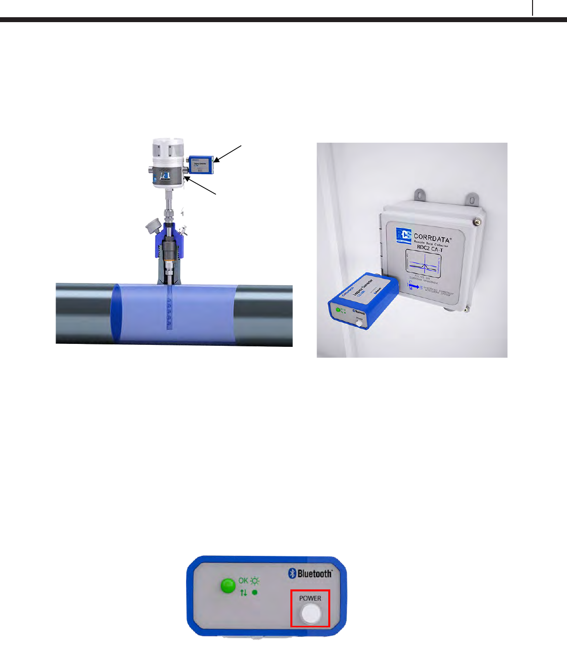
Legacy Converter
The Legacy Converter (LC-500) is an RS232 to Bluetooth serial converter that allows the Transfer
Unit to communicate with Cosasco legacy instruments in hazardous areas. This is done by plugging
the Legacy Converter directly into the communications port of the Cosasco legacy instrument.
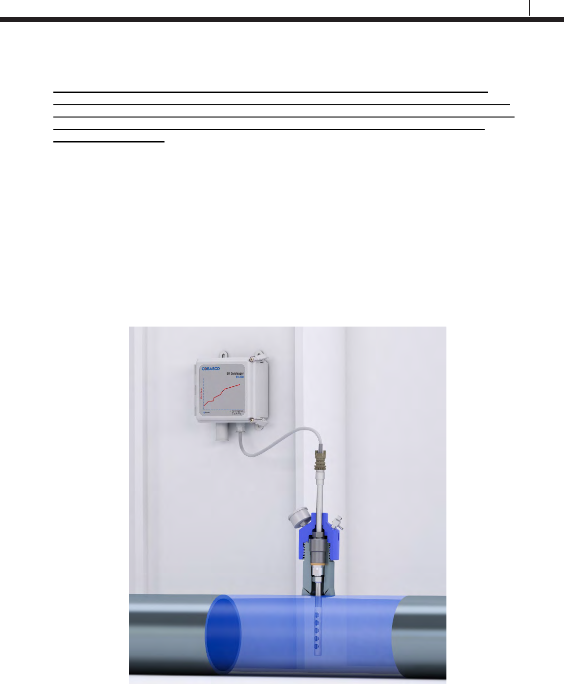
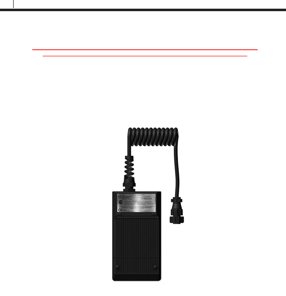
ER Datalogger
The ER Datalogger (ER-200) was designed to be used together with the Transfer Unit. The ER
Datalogger replaces the Remote Data Collector (RDC) that measures corrosion via ER Probe
measurements. The ER Datalogger interfaces with all standard Cosasco Electrical Resistance
probes and reads both corrosion data and temperature. For convenience, the ER Datalogger
communicates with the Transfer Unit via Bluetooth link used as a serial cable replacement.
LPR Datalogger
The LPR Datalogger (LPR-200) was designed to be used together with the Transfer Unit. The LPR
Datalogger replaces the Remote Data Collector (RDC) that measures corrosion via LPR Probe
measurements. The LPR Datalogger interfaces with all standard Cosasco Electrical Resistance
probes and reads both corrosion data and temperature. For convenience, the LPR Datalogger
communicates with the Transfer Unit via Bluetooth link used as a serial cable replacement.
Ultracorr 2
Note: For additional information regarding the Ultracorr 2, refer to the latest Ultracorr 2
Corrosion Monitoring System User Manual (Cosasco P/N: U-CORR2- MANUAL)
The new Ultracorr 2 is the next evolution in handheld Ultracorr Corrosion Monitoring Systems.
Ultracorr 2 provides a cost effective ultrasonic thickness measurement and temperature
measurement of a pipe or vessel wall using fixed transducers mounted at various locations
throughout a site.
After initial installation, access to the monitoring point is no longer required. The transducer
connector can be located at a convenient location for taking thickness and temperature readings.
These readings can then be downloaded to a personal computer running Cosasco Data Corrosion
Management Software for storage and trend analysis.
The Ultracorr 2 transducers are equipped with an integral RTD measuring temperature which
enables taking of simultaneous metal thickness and metal temperature readings. The instrument
uses temperature data to compensate for changes in the metal thickness readings due to
temperature variations. The new generation of transducers are embedded with smart sensors that
retain user configured ID characteristics.
A basic system consists of a smart transducer, the new Ultracorr 2 handheld instrument, data
collection device, and Cosasco Data Software package. Since it will often be advantageous to take
a reading of the transducer from some remote point, there are numerous cabling options to connect
these two items. For example, cables may be run from numerous transducers into a single junction
box at ground level, where multiple readings may be taken very quickly.
Although there are many applications for the Ultracorr Corrosion Monitoring System, there are three
basic system applications. Refer to chapter 4 and 5 for installation procedures for various
placement options.

3
Bluetooth Suite
Specifications
Transfer Unit (TU-500)
Battery Requirements:
2 x Cosasco AA Lithium Batteries (P/N 095820)
Operating Temperature:
-40°F to 158°F (-40°C to 70°C)
Dimensions:
6.24”H x 3.35”W x .91”D (15.8 cm x 8.51 cm x 2.31 cm)
LCD:
5 volt, 20 x 4 character LCD screen without backlight
Intrinsic Safety:
ATEX Certification
SIRA 14 ATEX 2263X
Ex ia IIC T4 Ga, Ta = -40°C to +70°C
Enclosure: IP20
For use only with Cosasco Batteries P/N 095820 or P/N 095818, do not mix.
IEC Ex Certification
IECEx SIR 14.0096X
Ex ia IIC T4 Ga, Ta = -40°C to +70°C
Enclosure: IP20 Minimum
For use only with Cosasco Batteries P/N 095820 or P/N 095818, do not mix.
North American Certifications
CSA Certification: 70007061
CSAUS Class I, Zone 0, AEx ia IIC T4 Ga, Ta = -40°C to +70°C
CCSA Ex ia IIC T4 Ga, Ta = -40°C to +70°C
Enclosure: IP20 Minimum
For use only with Cosasco Batteries P/N 095820 or P/N 095818, do not mix.
Data Storage:
• Stores up to 255 IDs, with up to 99 Microcor IDs
• ER Probe Reader, LPR Probe Reader, Ultracorr 2 Reader: 10 readings
• RDC – COT, ER Datalogger: 2048 readings without temperature
1024 readings including temperature
• RDC – CAT, LPR Datalogger: 1024 readings without temperature
512 readings including temperature
• Microcor Bluetooth: 16000 readings
• Microcor Legacy: 8000 readings
• Ultracorr 2 Datalogger: 2000 readings
Chapter 2

4
Specifications
Battery Life:
Approximately 2 days of continuous operation
Communication:
Bluetooth® as serial cable replacement
Microcor ER Datalogger (M-200)
Battery Requirements:
7.2V Lithium Power Module (P/N 748400)
Operation Temperature:
-40°F to 158°F (-40°C to 70°C)
Dimensions:
4.40”Diameter x 6.9”H (11.2 cm x 17.5cm)
Weight:
6.45lbs (2.9kg)
Operation:
• Compatible with all Cosasco Microcor Probes
• Battery Life: 2 years at 20 min measurement interval
Resolution:
18 bit (1 part in 262,144)
Data Storage:
16,000 Readings (Circular Buffer)
Communication:
Wired/RS232 or Bluetooth v2.0
Bluetooth Specifications:
• Bluetooth v2.0 + EDR
• FHSS/GFSK Modulation
• +2 dBi typical, +4dBi maximum Integral Antenna
• Frequency Range: 2402-2480 MHz

5
Bluetooth Suite
ER Probe Reader (ER-100)
Battery Requirements:
2 x Cosasco AA Lithium Batteries (P/N 095820)
Operating Temperature:
-40°F to 158°F (-40°C to 70°C)
Dimensions:
6.1”H x 2.4”W x 1.44”D (15.5 cm x 6.1 cm x 3.66 cm)
Intrinsic Safety:
ATEX Certification
SIRA 14 ATEX 2261X
Ex ib IIC T4 Gb, Ta = -40°C to +70°C
Enclosure: IP20 Minimum
For use only with Cosasco Batteries P/N 095820 or P/N 095818, do not mix.
IEC Ex Certification
IECEx SIR 14.0094X
Ex ib IIC T4 Gb, Ta = -40°C to +70°C
Enclosure: IP20 Minimum
For use only with Cosasco Batteries P/N 095820 or P/N 095818, do not mix.
North American Certifications
CSA Certification: 70043903
CSAUS Class I, Zone 1, AEx ib IIC T4 Gb, Ta = -40°C to +70°C
CCSA Ex ib IIC T4 Gb, Ta = -40°C to +70°C
Enclosure: IP20 Minimum
For use only with Cosasco Batteries P/N 095820 or P/N 095818, do not mix.
Operation:
• Compatible with all Cosasco ER Probes
• Battery Life: 1700 Readings
Communication:
Bluetooth® as serial cable replacement

6
Specifications
LPR Probe Reader (LPR-100)
Battery Requirements:
2 x Cosasco AA Lithium Batteries (P/N 095820)
Operating Temperature:
-40°F to 158°F (-40°C to 70°C)
Dimensions:
6.1”H x 2.4”W x 1.44”D (15.5 cm x 6.1 cm x 3.66 cm)
Intrinsic Safety:
ATEX Certification
SIRA 14 ATEX 2262X
Ex ib IIC T4 Gb, Ta = -40°C to +70°C
Enclosure: IP20
For use only with Cosasco Batteries P/N 095820 or P/N 095818, do not mix.
IEC Ex Certification
IECEx SIR 14.0095X
Ex ib IIC T4 Gb, Ta = -40°C to +70°C
Enclosure: IP20 Minimum
For use only with Cosasco Batteries P/N 095820 or P/N 095818, do not mix.
North American Certifications
CSA Certification: 70007055
CSAUS Class I, Zone 1, AEx ib IIC T4 Gb, Ta = -40°C to +70°C
CCSA Ex ib IIC T4 Gb, Ta = -40°C to +70°C
Enclosure: IP20 Minimum
For use only with Cosasco Batteries P/N 095820 or P/N 095818, do not mix.
Operation:
• Compatible with all Cosasco LPR Probes
• Battery Life: 2000 Readings
Communication:
Bluetooth® as serial cable replacement

7
Bluetooth Suite
Legacy Converter (LC-500)
Battery Requirements:
2 x Cosasco AA Lithium Batteries (P/N 095820)
Operating Temperature:
-40°F to 158°F (-40°C to 70°C)
Dimensions:
4.0”H x 2.5”W x 1.3”D (10.3 cm x 6.4 cm x 3.3 cm)
Intrinsic Safety:
ATEX Certification
SIRA 14 ATEX 2264X
Ex ib IIC T4 Gb, Ta = -40°C to +70°C
Enclosure: IP20
For use only with Cosasco Batteries P/N 095820 or P/N 095818, do not mix.
IEC Ex Certification
IECEx SIR 14.0097X
Ex ib IIC T4 Gb, Ta = -40°C to +70°C
Enclosure: IP20 Minimum
For use only with Cosasco Batteries P/N 095820 or P/N 095818, do not mix.
North American Certifications
CSA Certification: 70008374
CSAUS Class I, Zone 1, AEx ib IIC T4 Gb, Ta = -40°C to +70°C
CCSA Ex ib IIC T4 Gb, Ta = -40°C to +70°C
Enclosure: IP20 Minimum
For use only with Cosasco Batteries P/N 095820 or P/N 095818, do not mix.
Operation:
• Compatible with all Cosasco legacy instruments (Excluding RDC 4 Channel)
• Battery Life: Approximately 2 days of continuous operation
Communication:
Bluetooth® as serial cable replacement

8
Specifications
ER Datalogger (ER-200)
Battery Requirements:
Cosasco RDC2 Battery Pack P/N 726043
Operating Temperature:
-40°F to 158°F (-40°C to 70°C)
Dimensions (Approximately):
9.05”H x 6.5”W x 4.25”D (22.987 cm x 16.51 cm x 10.795 cm)
Intrinsic Safety:
ATEX Certification
SIRA 16ATEX2024X
Ex ia IIC T4 Ga, Ta = -40°C to +70°C
For use only with RCS RDC2 Battery Pack P/N 726043
Enclosure: IP20
IEC Ex Certification
IECEx SIR 16.0009X
Ex ia IIC T4 Ga, Ta = -40°C to +70°C
For use only with RCS RDC2 Battery Pack P/N 726043
Enclosure: IP20 Minimum
North American Certifications
CSA Certification: 70008419
CSAUS Class I, Zone 0, AEx ia IIC T4 Ga, Ta = -40°C to +70°C
CCSA Ex ia IIC T4 Ga, Ta = -40°C to +70°C
For use only with RCS RDC2 Battery Pack P/N 726043
Enclosure: IP20 Minimum
Operation:
• Compatible with all standard Cosasco ER Probes
• Battery Life: 1.9 years at 1 measurement every 4 hours
Communication:
Bluetooth® as serial cable replacement

9
Bluetooth Suite
LPR Datalogger (LPR-200)
Battery Requirements:
Cosasco RDC2 Battery Pack P/N 726043
Operating Temperature:
-40°F to 158°F (-40°C to 70°C)
Dimensions (Approximately):
9.05”H x 6.5”W x 4.25”D (22.987 cm x 16.51 cm x 10.795 cm)
Intrinsic Safety:
ATEX Certification
SIRA 16ATEX2025X
Ex ia IIC T4 Ga, Ta = -40°C to +70°C
For use only with RCS RDC2 Battery Pack P/N 726043
Enclosure: IP20
IEC Ex Certification
IECEx SIR 16.0010X
Ex ia IIC T4 Ga, Ta = -40°C to +70°C
For use only with RCS RDC2 Battery Pack P/N 726043
Enclosure: IP20 Minimum
North American Certifications
CSA Certification: 70014313
CSAUS Class I, Zone 0, AEx ia IIC T4 Ga, Ta = -40°C to +70°C
CCSA Ex ia IIC T4 Ga, Ta = -40°C to +70°C
For use only with RCS RDC2 Battery Pack P/N 726043
Enclosure: IP20 Minimum
Operation:
• Compatible with all standard Cosasco LPR Probes
• Battery Life: 1 year at 1 reading every 4 hours
Communication:
Bluetooth® as serial cable replacement
10
Specifications
Ultracorr 2 (U-200)
Ultracorr 2 Instrument
Battery Requirements:
2 x 3.6V AA Lithium Cells (Cosasco P/N 095820)
Battery Life:
Over 6000 readings
Operating Temperature:
-40°F to 158°F (-40°C to 70°C)
Storing Temperature:
-40°F to 158°F (-40°C to 70°C)
Dimensions:
6”H x 3.25”W x 1.25”D (152.4 mm x 82.55 mm x 31.75 mm)
Weight:
1 lb. (0.45 kg)
Intrinsic Safety:
For USA/Canada: Ex ib IIC T4: Class I, Zone 1 AEx ib IIC T4
For Europe: II 2G
Ex ib IIC T4 Gb
Ta = -40°C to +70°C
UST2 Ultrasonic Sensor
Thickness Measurement:
Range: 0.2 (0.1 for special orders) to 2.0 inches, up to 25 ft. cable
Resolution: 0.0001 inch
Accuracy: ± 0.0002 inch at constant temperature
± 0.0005 inch from -40°C to +70°C (Instrument)
± 0.0003 inch from -40°C to +150°C (Metal Surface of Transducer)
Transducer Temperature:
Range: Ambient: -40°F to +158°F (-40°C to +70°C)
Metal Surface: -40°F to +305°F (-40°C to +150°C)
Temperature Compensation:
-0.0002 inch/inch/°C
Temperature Differential Error:
-0.0001 inch/inch/°C difference (inside to outside of wall)

11
Bluetooth Suite
Temperature Measurement:
Range: -40°C to +150°C
Resolution: 0.1°C
Accuracy: ±2°C (Transducer)
±2°C (Instrument)
Data Storage:
Memory Type: Nonvolatile
Probes: 255
Readings/Probes: 2000
Date and Time Stamped
Interface:
Bluetooth®
Transducer Type:
Contact
Transducer Cable:
RG-174 up to 25 ft.

12
Specifications
13
Bluetooth Suite
Basics of the Bluetooth Suite
Transfer Unit
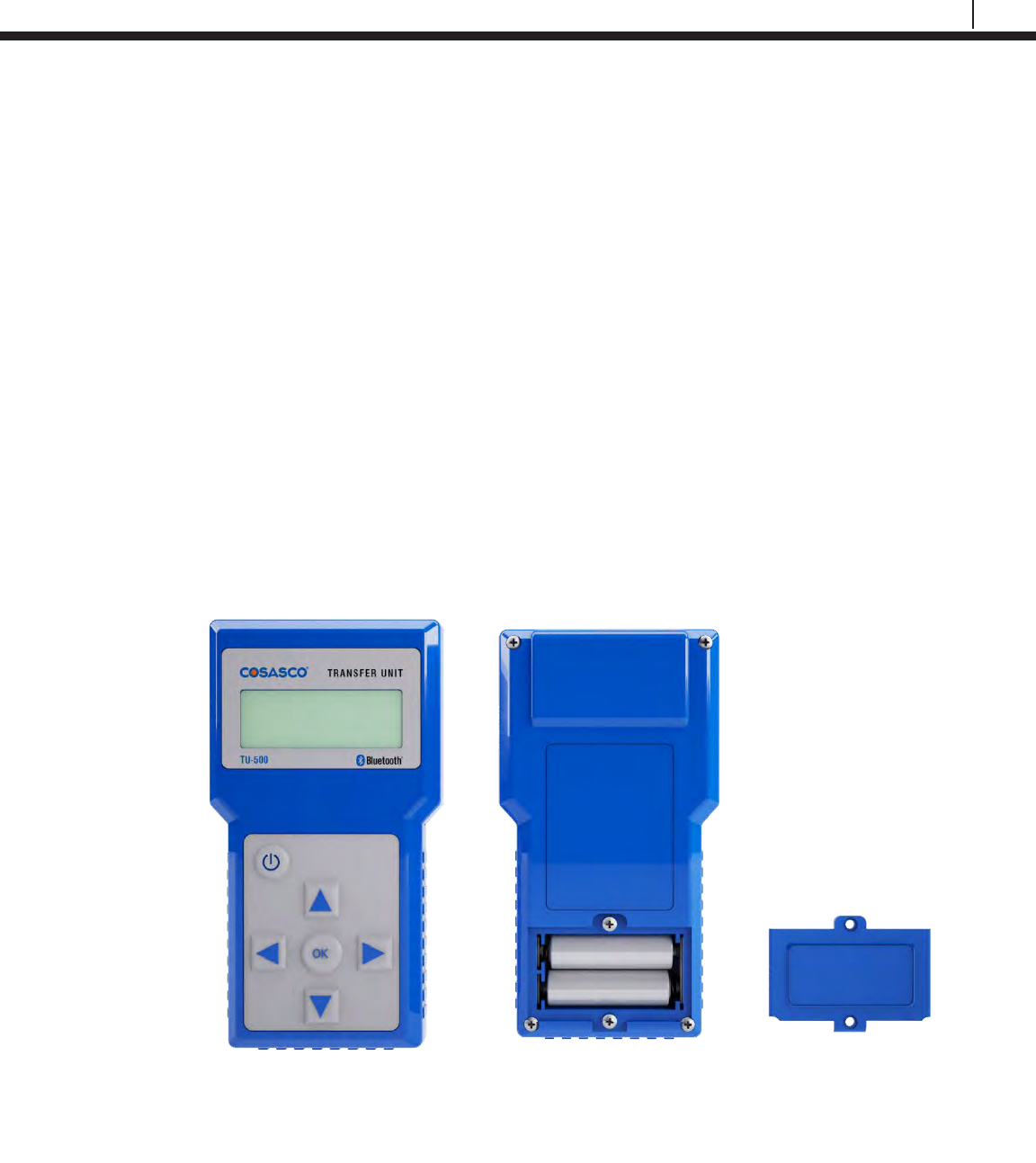
Battery Installation
The Transfer Unit is supplied with two 3.6 Volt AA lithium batteries. To install these batteries,
remove the rear access panel of the unit with a screwdriver and install the batteries with the
polarities as indicated on the unit. Replace the rear access panel when finished.
Chapter 3
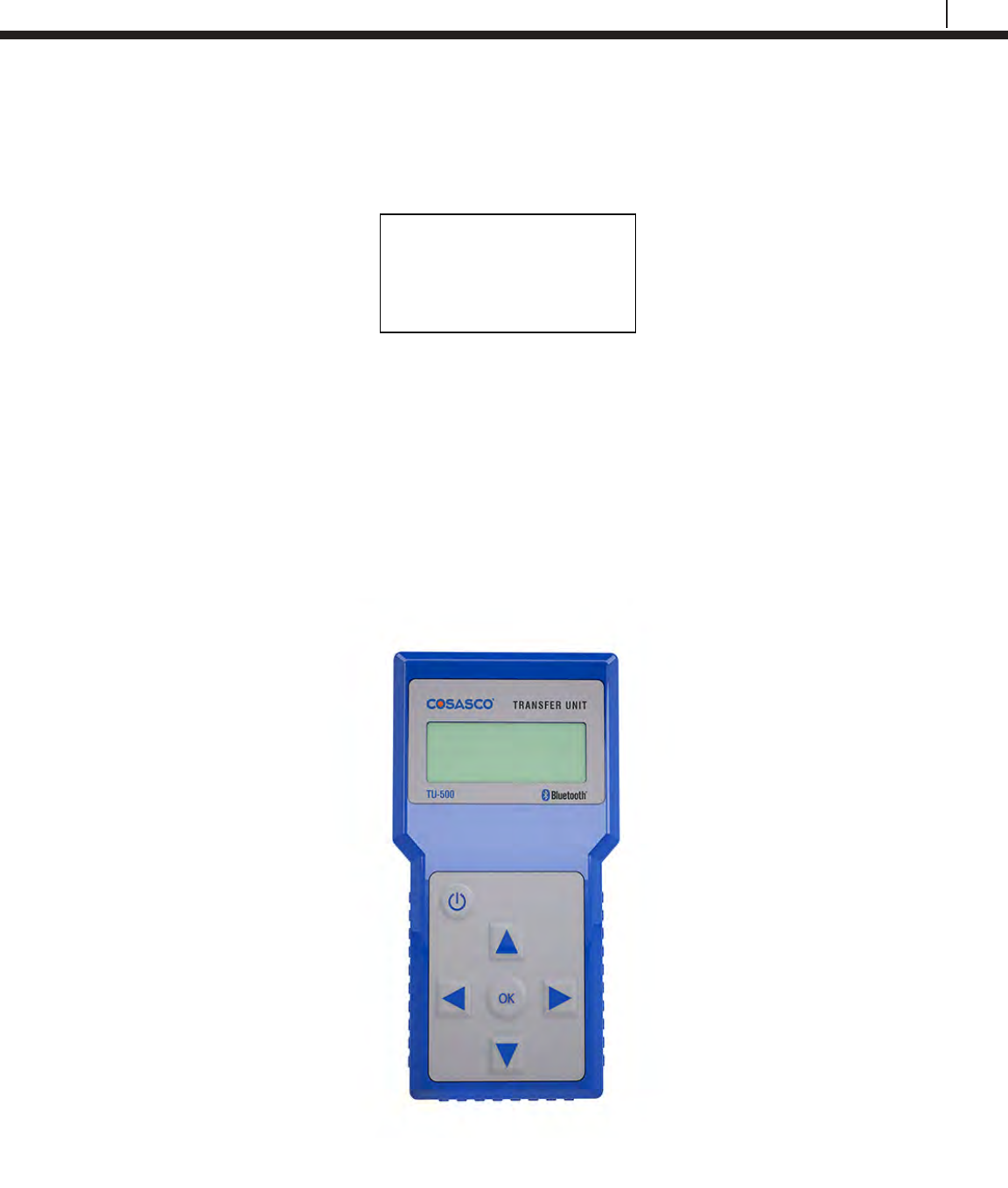
TU-500 Transfer Unit
Front View
Transfer Unit
Back View
14
Basics of the Bluetooth Suite
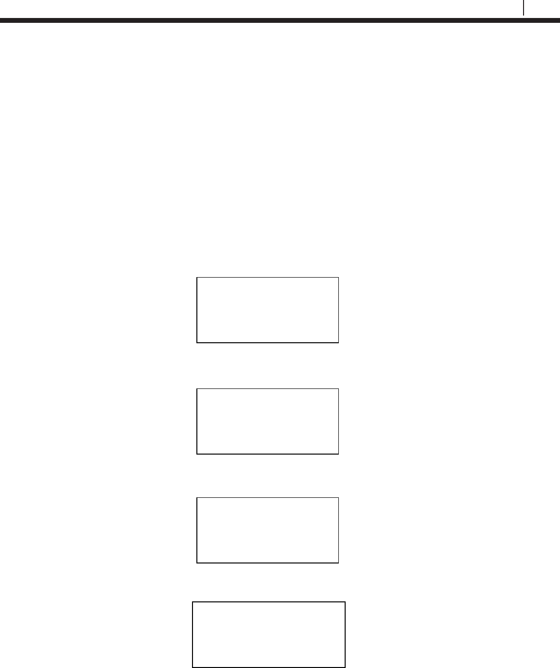
Standby Screens
The Standby screens are shown below. To navigate between the two standby screens use the
More and Back options.
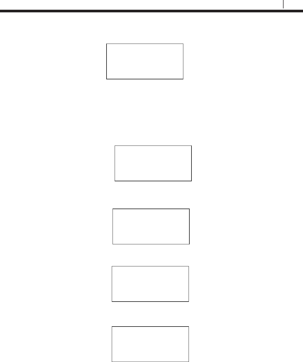
Scanning for Devices
To scan for devices, select the Scan option on the standby screen. The following screen will
appear. Select and amount of time, 10s, 20s, or 30s, to scan for devices.
Note: It is recommended to use the 30s scan time to allow for Bluetooth to sync.
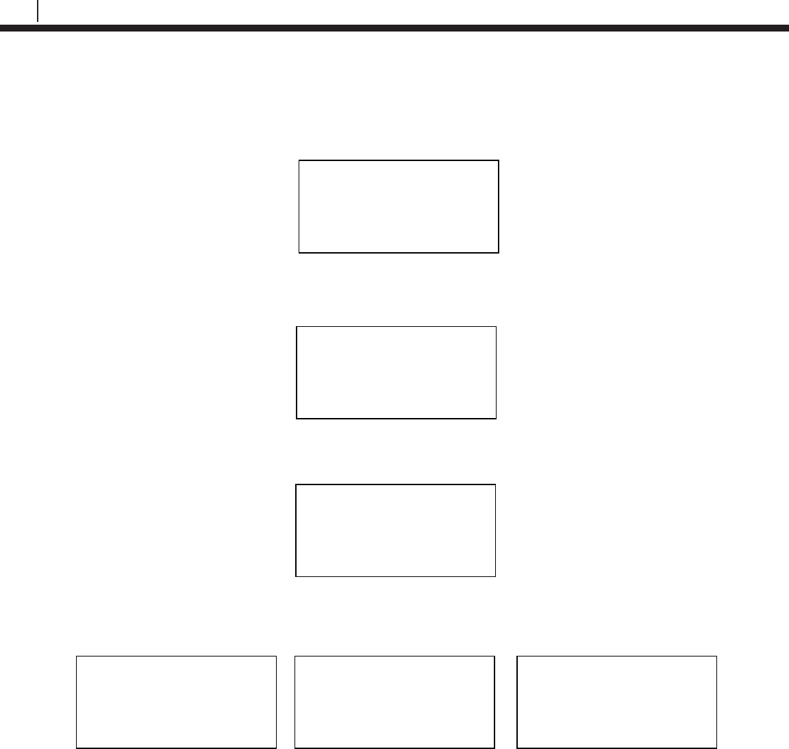
The Transfer Unit will show the following screens while scanning for devices.
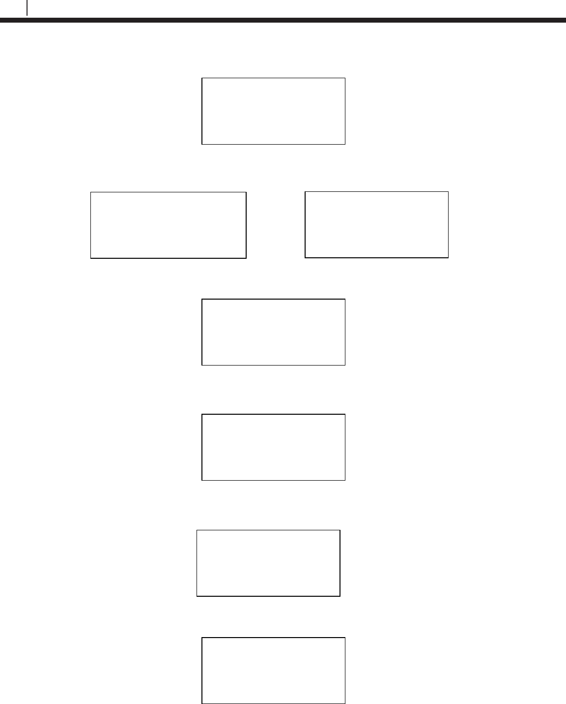
When the Transfer Unit has finished scanning, scroll through the list of found devices using the
up and down arrows on the keypad. The user can select Sv to save the device to a list.
Note: Up to 10 devices can be stored into the saved device list.
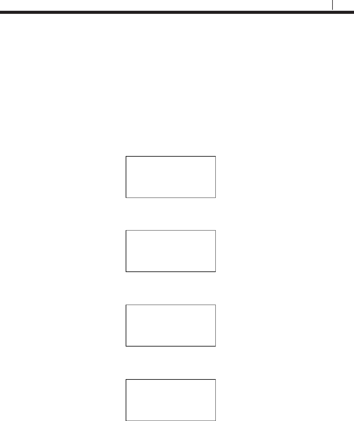
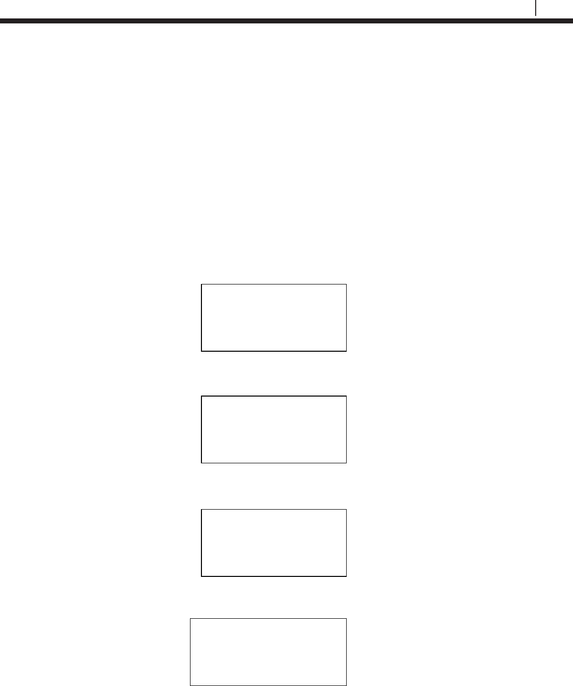
Select Scan Time
10s | 20s | 30s | Exit
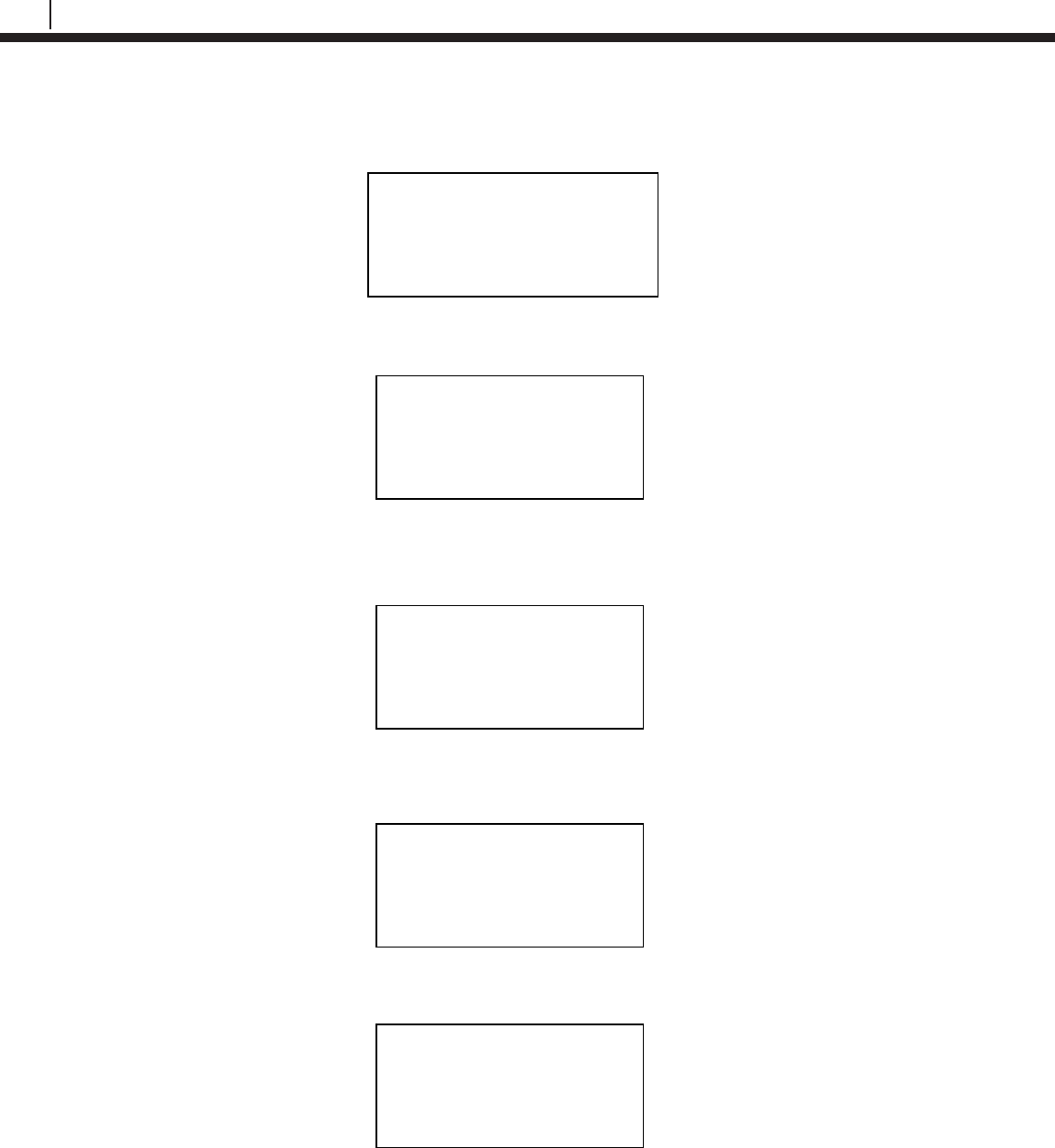
Scanning. . .
Please Wait
XX
Found X
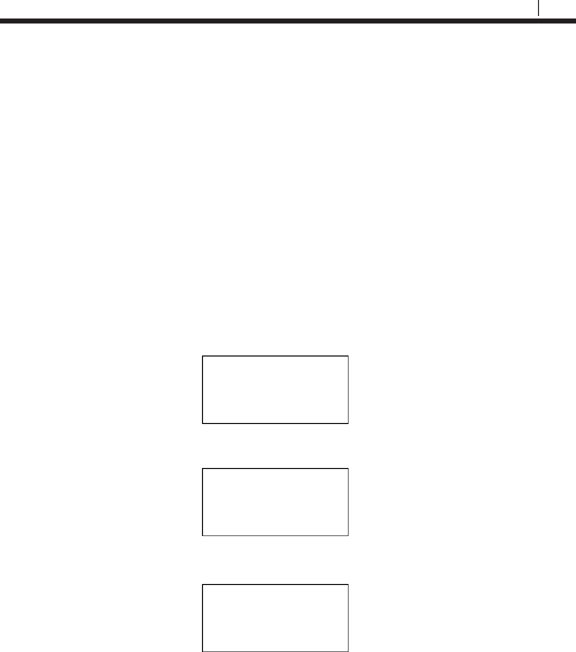
►►►►►►►►►►►
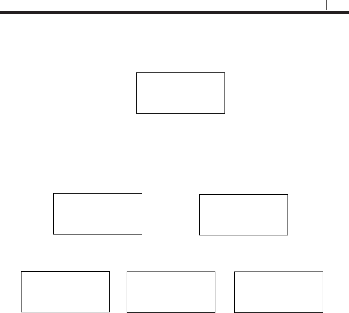
COSASCO TU-500 vX.XX
MM/DD/YY HH:MM:SS
Confg | Scan | Device
Disp
| PC
| More
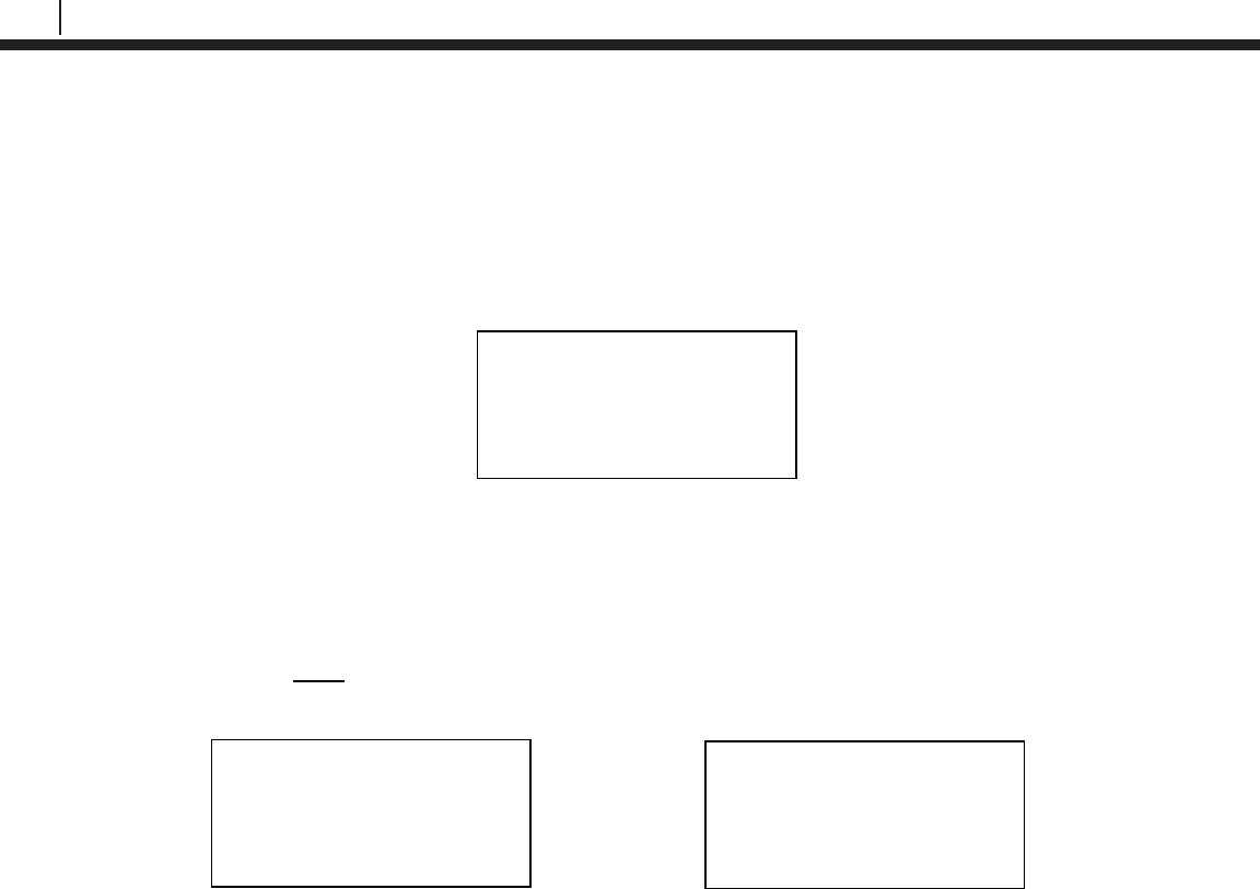
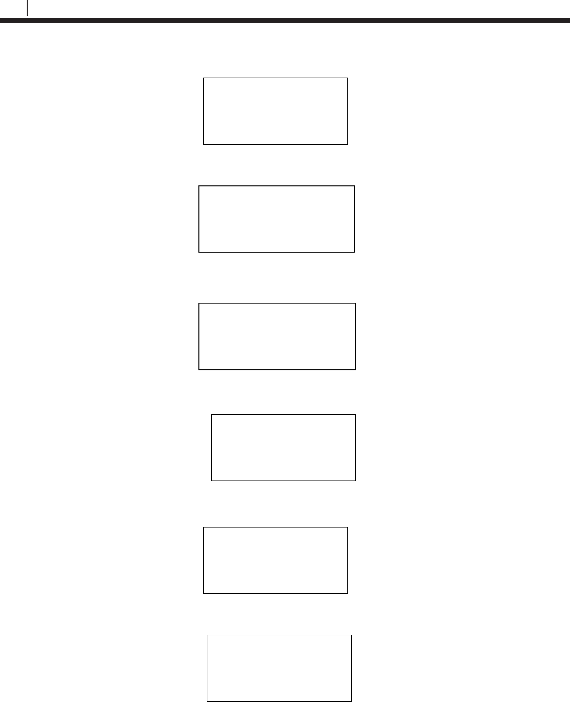
COSASCO TU-500 vX.XX
MM/DD/YY HH:MM:SS
Time | Units | Memory
Back |
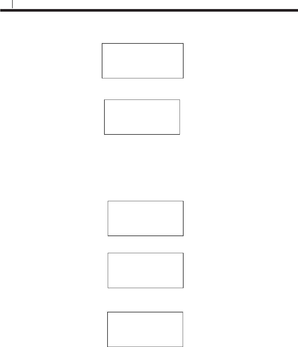
Devices [UP/DOWN] X
[XXXXXXXXXX ]
Bk=Back Sv=Save
Cfg | Dl | St | Bk | Sv
15
Bluetooth Suite
Device List
After scanning for devices, the Transfer Unit allows the user to view the devices found from the
last scan or view the list of saved devices. These options allow the user to bypass the scanning
command and directly access a list of devices.
From the Standby screen select Device.
On this screen, the user will have the option for Last Scan, Saved List and Exit.
• Last Scan will bring the user to the list of devices from the last scan.
• Saved List will bring the user to the list of saved devices.
• Exit will return the user to the standby screen.
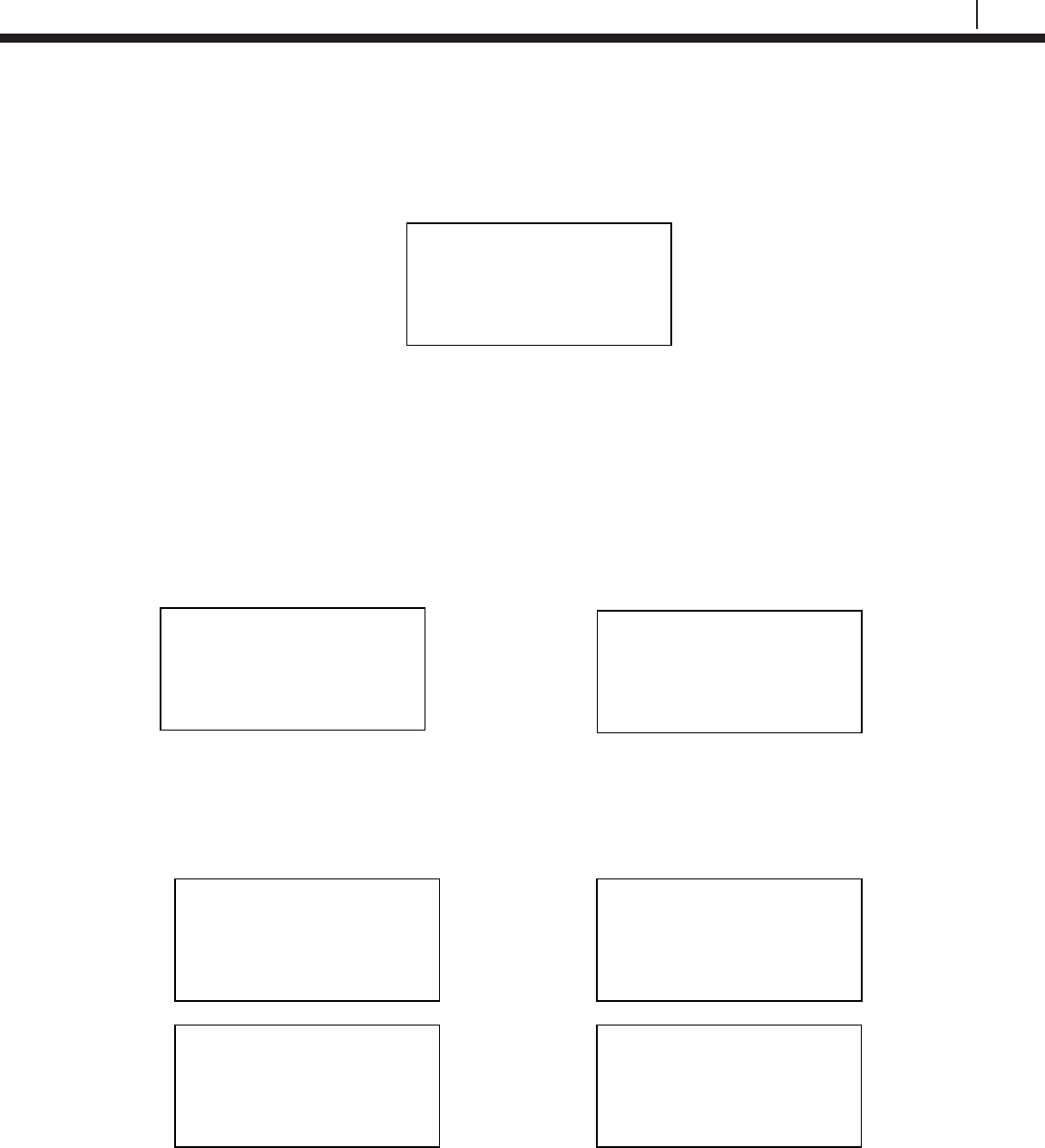
Display Configured IDs
The Transfer Unit gives the user the option to view configured ID’s through the standby screen.
On the standby screen select Disp.
On the following screen, the user has the option to display configured ID’s by selecting either
Current or ID. If Current is selected the Transfer Unit will display the last viewed ID and if ID is
selected the Transfer Unit will allow the user to enter a device’s ID number. Different information
will be displayed depending on the type of ID configured.
Display Saved ID
Current | ID | Exit
COSASCO TU-500 vX.XX
MM/DD/YY HH:MM:SS
Confg | Scan | Device
Disp
| PC
| More
Device Menu
Last Saved
Scan | List | Exit
COSASCO TU-500 vX.XX
MM/DD/YY HH:MM:SS
Confg | Scan | Device
Disp
| PC
| More
16
Basics of the Bluetooth Suite
Setting Units
To change the units on the Transfer Unit select Units from the standby screen. The following
screen will appear with the options for Temperature being F (Fahrenheit) and C (Celsius) and the
options for Metal Loss being mils, µm, and mm.
The option that is currently selected for temperature or metal loss will be shown next to
Temperature and Metal Loss respectively. To change the units, navigate to the preferred unit
then hit OK. When finished selecting the units, select Back to return to the standby screen.
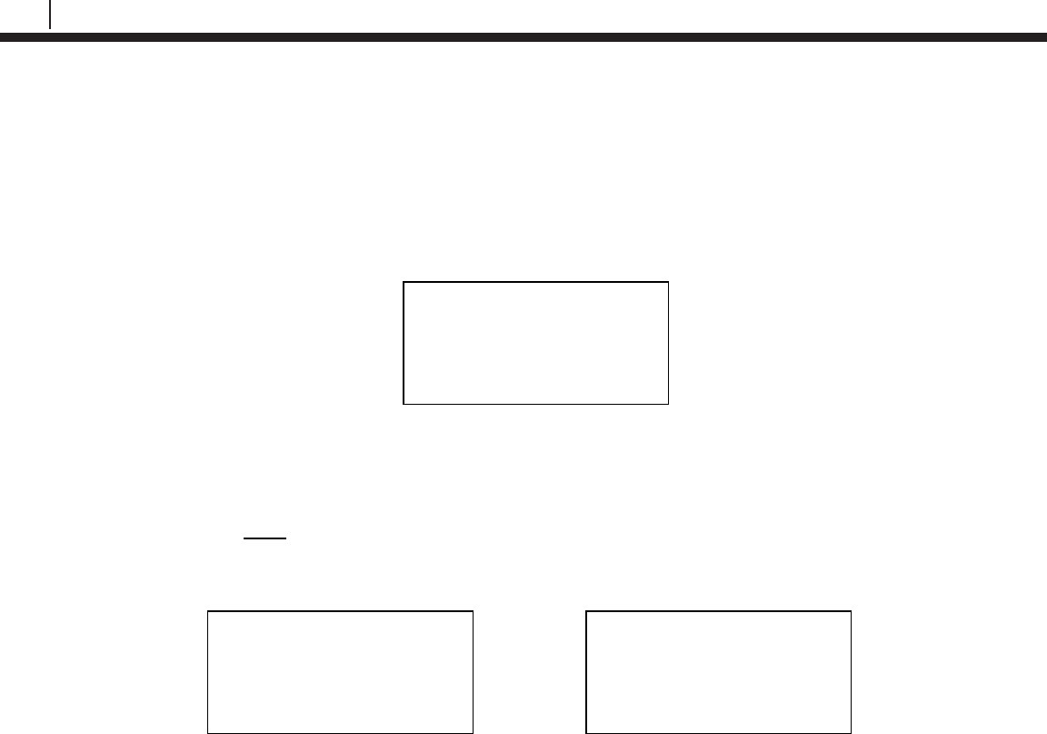
Setting Time
To change or set the time on the Transfer Unit select Time from the standby screens. The
following screen will appear with the options for Mate and Zone.
Choosing Mate will take the user to the following screen and will allow the user to manually enter
the time and date in military time.
YY – Year, MM – Month, DD – Day of the month, dd – Day of the week where 00 is Sunday,
hh – Hours, mm – Minutes, ss – Seconds
Choosing Zone will take the user to the following screen and will allow the user to select a time
zone and an offset. Select either STZ (Standard Time Zone) or DTZ (Daylight Time Zone) and
scroll up and down using the up and down arrows on the keypad to change the offset.
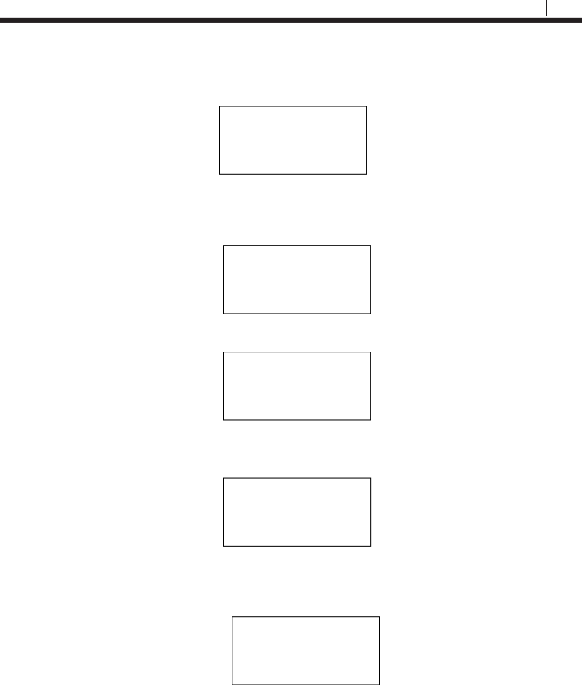
Units
Temperature: F
Metal Loss: mils
C | μm | mm | Back
Time set up
Mate | Zone
Back | Exit
Enter date/time in
YYMMDDddhhmmss
<XXXXXXXXXXXXXX>
0123456789.< OK Back
Time Zone: STZ
< X:XX >
Scroll Up and Down
DTZ | Back
17
Bluetooth Suite
Clearing Memory
From the standby screen select the option Memory. The following screen will appear with the
options to clear memory for a specific device’s ID number, Units, Device or All.
• If the user selects ID, enter the ID number of the device to delete the data off the Transfer
Unit then select OK. On the next display screen select Okay to clear the data for that ID.
This will clear all of the data stored for this specific ID including configuration and data.
• If the user selects Units, the preferences for the units stored on the Transfer Unit will be
restored to the defaults. Temp: C, Metal loss: mils, Time zone: STZ, -8:00 offset.
• If the user selects Device, this will clear the memory for saved scan BT devices and last
scanned BT devices.
• If the user selects All, this will clear all stored ID numbers configuration and data, restore
all units to their default and clear all stored scanned devices.
TU-500 Transfer Unit
Clear Memory
ID | Units | Device
All | Back | Exit
18
Basics of the Bluetooth Suite
Microcor ER Datalogger
Power Module Installation
Power Module (Cosasco P/N 748400) is intrinsically safe and may be connected/disconnected in
a hazardous location.
Configuration for hazardous/non-hazardous locations (computer software may only be used in a
non-hazardous location).
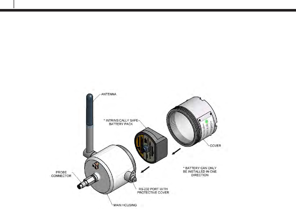
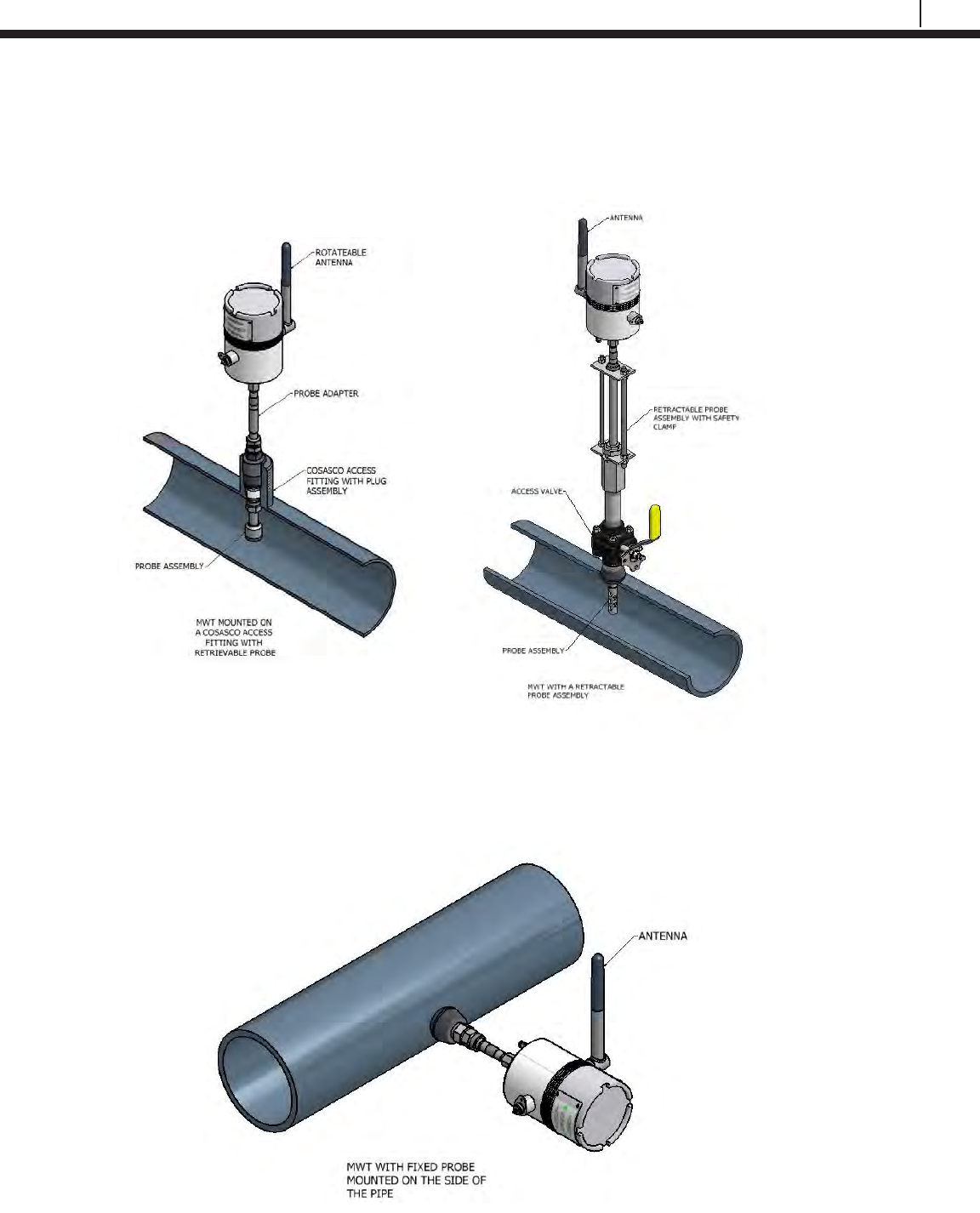
Mounting the Microcor ER Datalogger
The Microcor ER Datalogger can be installed on the top, side or bottom of the line according to
the probe installation. Choose the best installation configuration that corresponds to the location
of the probe.
Grounding
A 8 to 14 AWG grounding wire can be attached to the datalogger at the grounding lug. Connect
the ground wire to earth ground per local electrical code.
19
Bluetooth Suite
Direct Probe Mounting
Top of the Line
1. Attach connector and tighten connector nut to mount the transmitter to the probe adapter.
2. Rotate the antenna to vertical position.
Side of the Line
1. Attach connector and tighten connector nut to mount the transmitter to the probe adapter.
2. Rotate the antenna to vertical position.
20
Basics of the Bluetooth Suite
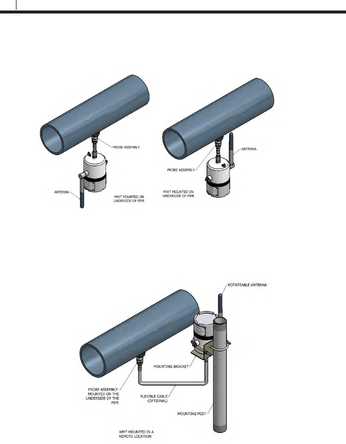
Bottom of the Line
1. Attach connector and tighten connector nut to mount the transmitter to the probe adapter.
2. Rotate the antenna to vertical position.
Optional Remote Mounting
(Bottom of the Line shown)
1. Secure the transmitter to the remote mounting post using appropriate accessories.
2. Attach connector and tighten connector nut of the optional flexible cable to the probe adapter and attach the other end to the
transmitter.
3. Rotate the antenna to vertical position.
21
Bluetooth Suite
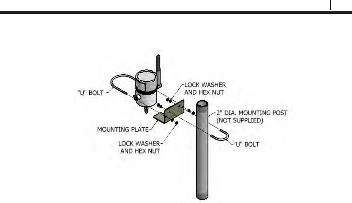
Cosasco Mounting Accessories
22
Basics of the Bluetooth Suite
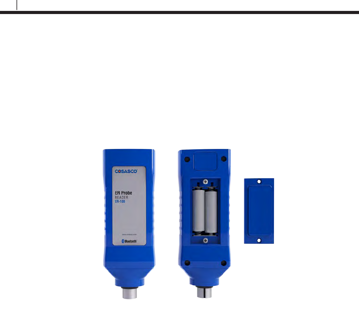
ER Probe Reader and LPR Probe Reader
Battery Installation
Both Probe Readers are supplied with two 3.6 Volt AA lithium batteries. To install these batteries,
remove the rear access panel of the unit with a screwdriver and install the batteries with the
polarities as indicated on the unit. Replace the rear access panel when finished.
ER-100 Probe Reader
ER-100 Reader Back View
23
Bluetooth Suite
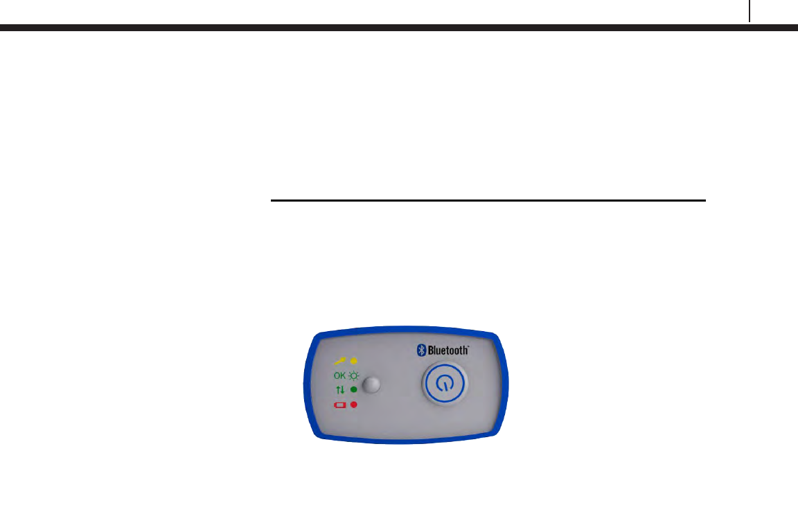
Checking Battery Status
To check the battery status of the Probe Readers, turn on the Probe Reader by pushing the
power button on the top of the device. If the LED on the top of the device is green, the Probe
Reader has good batteries. If the LED on the top of the device is red or unit does not respond,
the user needs to change the batteries of the Probe Reader before taking a reading. Replace
batteries as indicated on the ER Probe Reader and LPR Probe Reader Battery Installation
section.
ER-100 Reader Top View
24
Basics of the Bluetooth Suite
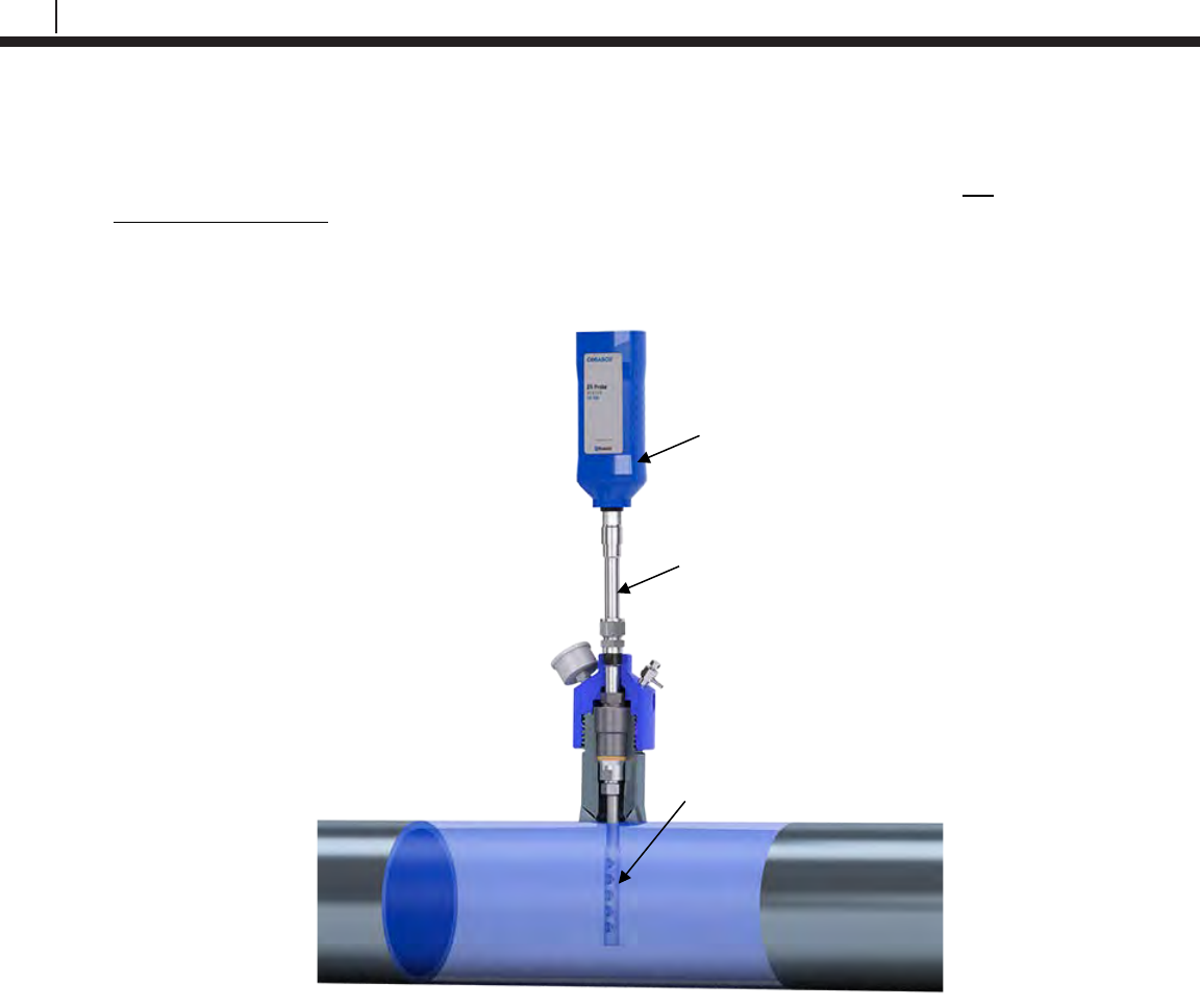
Using the ER Probe Reader
To use the ER Probe Reader, the user must first attach the ER Probe Reader to an ER
probe/probe adapter.
Turn on the ER Probe Reader by pushing the power button on the top of the device. The LED of
the ER Probe Reader will be green when ready to take a probe reading. When the ER Probe
Reader is taking a reading of the probe, the LED will be yellow/orange. When the ER Probe
Reader has finished taking a reading of the probe, the LED will return back to green.
ER-100 Probe Reader
ER Probe
ER Probe Adapter
25
Bluetooth Suite
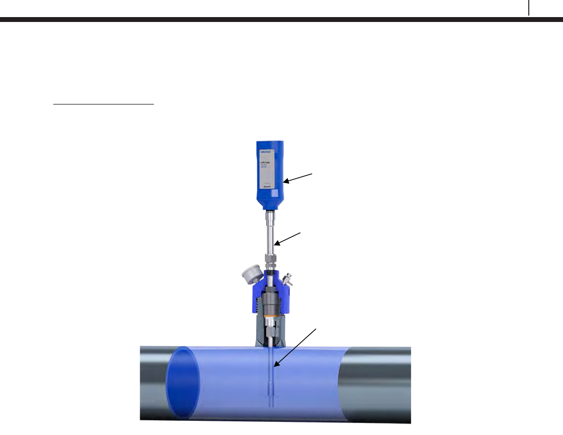
Using the LPR Probe Reader
To use the LPR Probe Reader, the user must first attach the LPR Probe Reader to an LPR
probe/probe adapter.
Turn on the LPR Probe Reader by pushing the power button on the top of the device. The LED of
the LPR Probe Reader will be green when ready to take a probe reading. When the LPR Probe
Reader is taking a reading of the probe, the LED will be yellow/orange. When the LPR Probe
Reader has finished taking a reading of the probe, the LED will return back to green.
Turn Off Probe Readers
To turn off the ER Probe Reader or LPR Probe Reader, push and hold down the power button
until the LED turns red.
LPR-100 Probe Reader
LPR Probe
LPR Probe Adapter
26
Basics of the Bluetooth Suite
Legacy Converter
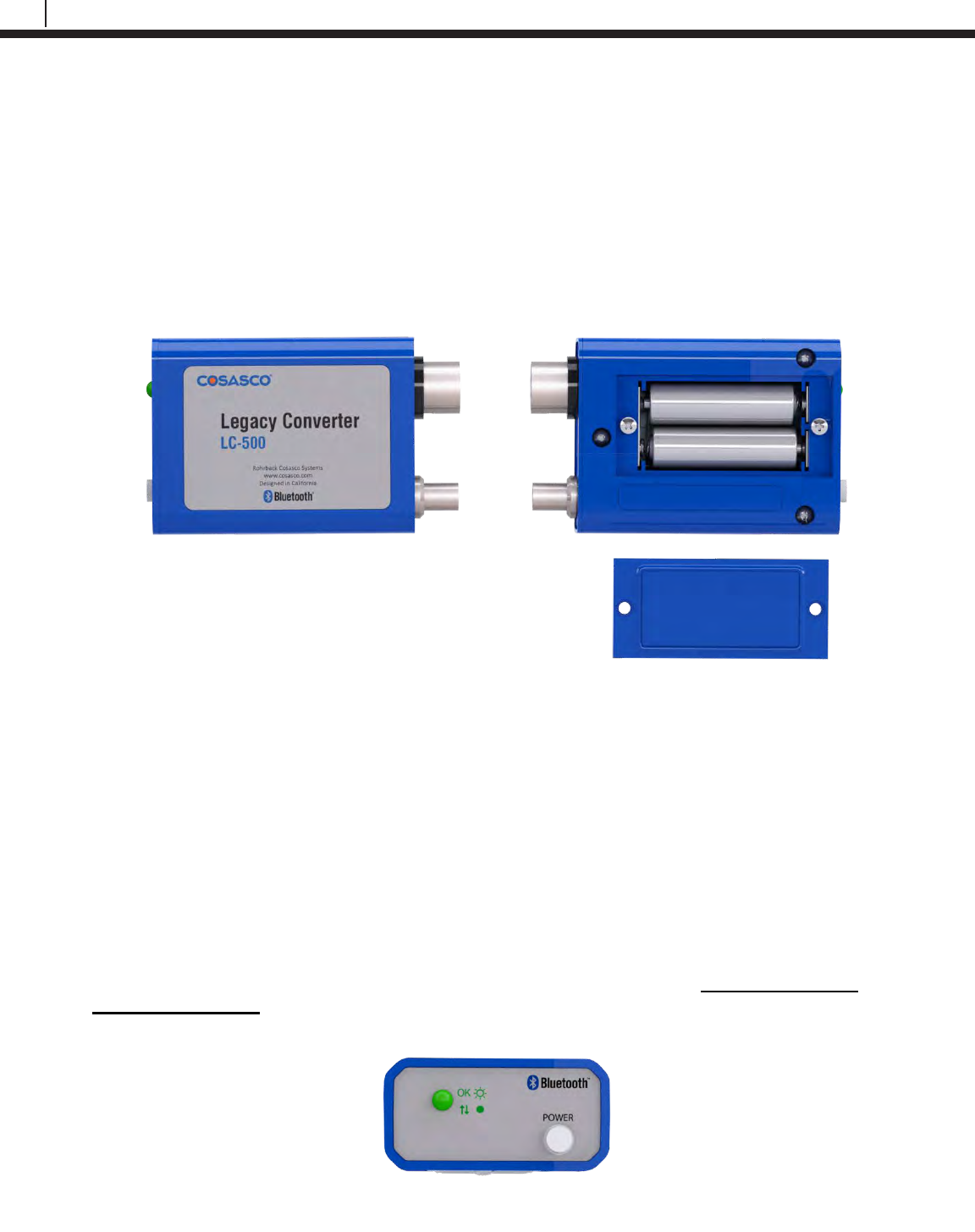
Battery Installation
The Legacy Converter is supplied with two 3.6 Volt AA lithium batteries. To install these batteries,
remove the rear access panel of the unit with a screwdriver and install the batteries with the
polarities as indicated on the unit. Replace the rear access panel when finished.
Checking Battery Status
To check the battery status of the Legacy Converter, turn on the device by pushing down the
power button. If the LED on the device does not flash green after approximately 2 seconds the
user needs to change the batteries. Replace batteries as indicated on the Legacy Converter
Battery Installation section.
LC-500 Legacy Converter
LC-500 Converter Back View
LC-500 Converter Top View
27
Bluetooth Suite
Using the Legacy Converter
Attach the Legacy Converter directly to the communications port of the Cosasco Legacy Device.
Turn on the device by pushing the white power button. The LED on the Legacy Converter will
flash green when ready to be used with the Transfer Unit.
Turn Off Legacy Converter
To turn off the Legacy Converter, push the white power button and the LED will turn off.
Legacy Converter
ER Communication
Port
Communication Port

28
Basics of the Bluetooth Suite
ER Datalogger and LPR Datalogger
Battery Installation
NOTE: If LED flashes green when battery is installed, use the TU-500 to download data and
reconfigure the Datalogger.
Both Dataloggers are supplied with a battery pack (Cosasco P/N 726043). To install this battery
pack, open the unit by releasing the latches, remove the thumb screws and washers, place the
battery onto the screw mounts and make sure the arrows are pointing upwards, insert the
washers, hand tighten the thumb screws and connect the power connecters together. Once
finished, close the unit by re-latching the latches.
29
Bluetooth Suite
Installation
THE FOLLOWING ARE ONLY RECOMMENDED PRACTICES. INSTALLATION OF THIS
DATALOGGER IN AN EXPLOSIVE ENVIRONMENT MUST BE IN ACCORDANCE WITH THE
REQUIREMENTS FOR INSTALLATION OF INTRINSICALLY SAFE SYSTEMS IN HAZRDOUS
(CLASSIFIED) LOCATIONS, PER LOCAL CODE SUCH AS THE NATIONAL ELECTRIC
CODE (ANSI/NFPA70)
Location
The ER and LPR Dataloggers are certified for Zone 0 Hazardous Environment operation. The
Dataloggers are designed for continuous operation between -40˚C to 70˚C. If extremes are
expected outside of this operation range, sufficient protection to the thermal differences should be
used for optimal lifespan of the device.
Mounting the Device
The ER and LPR Dataloggers cannot be directly mounted to a probe and are typically remote
mounted with a 10’ (typical) probe cable connecting to a probe location. A typical ER Datalogger
or LPR Datalogger mounting example is shown below.
30
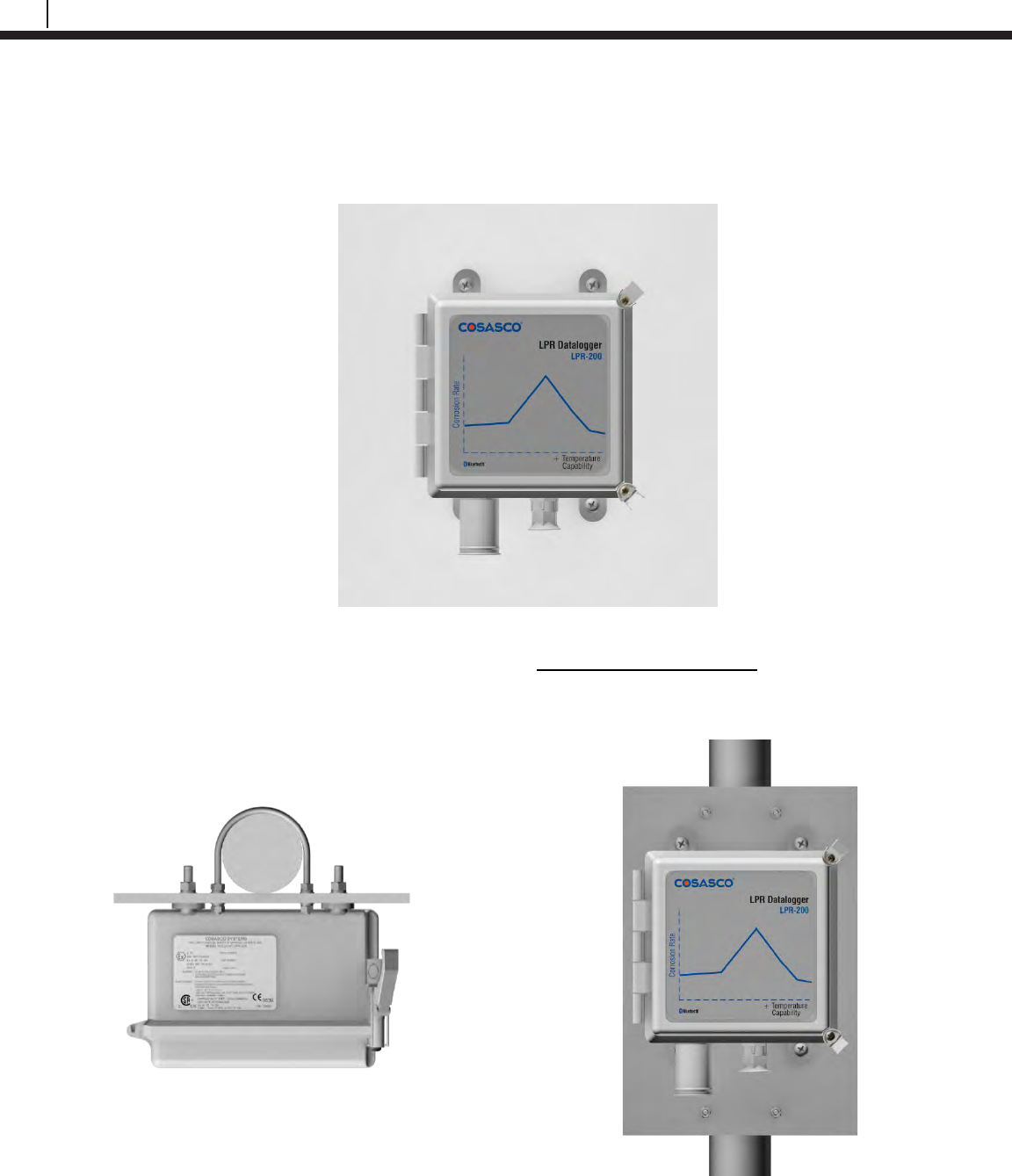
Basics of the Bluetooth Suite
Two common ways to mount the device are remote wall mounting and 2” pipe mounting.
Remote wall mounting: Ensure the device is mounted vertically with the probe cable entrance
pointed down.
Pipe mounting: This mounting technique is for the Fiberglass Enclosure only. Mount the device
to the mounting plate and attach the U bolts around the pipe and secure with the nuts.
Note: Only the U bolts will be provided.
31
Bluetooth Suite
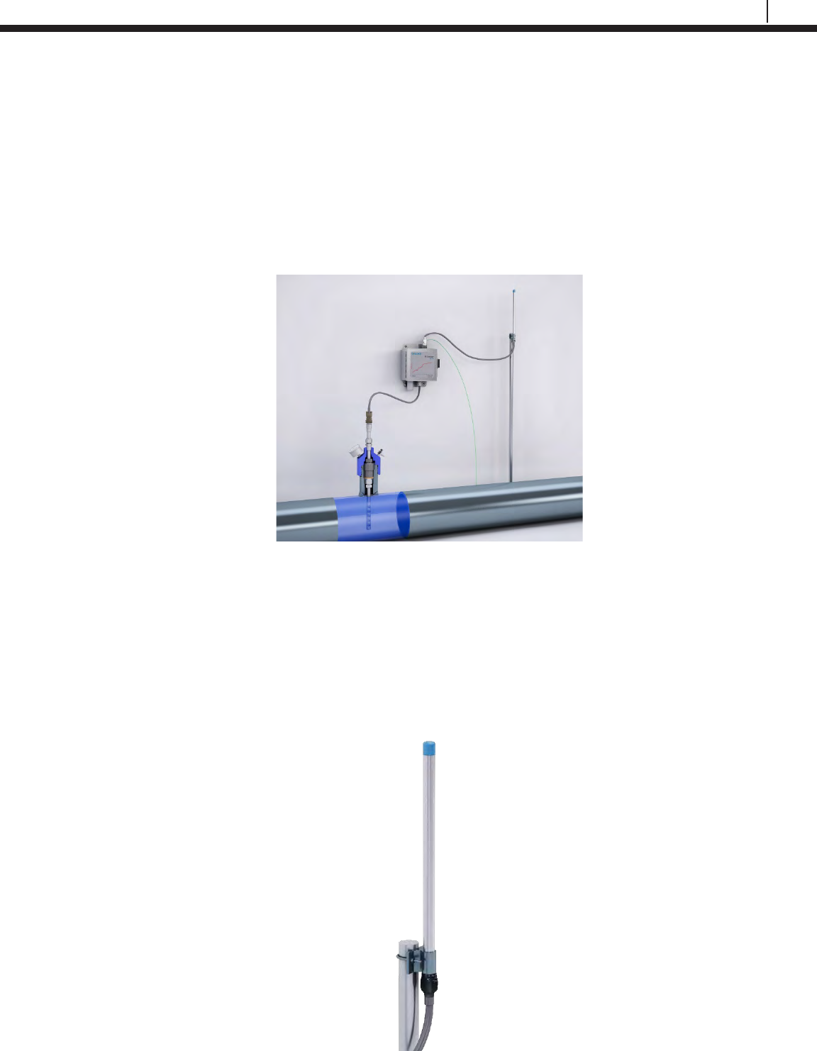
Grounding
This is applicable to the ER-200 or LPR-200 Stainless Steel enclosure and units with remote
mounted antenna.
An 8 to 14 AWG grounding wire can be attached to the Datalogger at the mounting hole. Install
grounding wire per local Electric code.
Attach a grounding wire into the lightning arrestor and enclosure if the remote mount antenna is
used.
Mounting the Remote Mount Antenna
The remote mount antenna is provided with the installation hardware. This uses a U bolt for
installation.
Secure the antenna to the mounting location using the U bolt. After the antenna is secured apply
the provided sealing tape to both Lightning arrestor and to antenna connector to help ensure
maximum device lifespan.
32
Basics of the Bluetooth Suite
Ultracorr 2
Note: For additional information regarding the Ultracorr 2, refer to the latest Ultracorr 2
Corrosion Monitoring System User Manual (Cosasco P/N: U-CORR2- MANUAL)
Battery Installation
The Ultracorr 2 is supplied with a set of two 3.6 Volt lithium batteries (Cosasco PN 095820). To
install these batteries, remove the access panel on the back of the unit (see below) and install the
batteries with the polarities as indicated on the unit. Replace the back cover when finished.
33
Bluetooth Suite
Transfer Unit
Microcor ER Datalogger
Create an ID for Microcor ER Datalogger
On the standby screen of the Transfer Unit select Confg. On the next display screen, select
Microcor to get to a list of Microcor devices.
Select M-200 for the Microcor ER Datalogger (M-200).
Enter the desired ID number then select OK.
Enter the interval then select m for minutes.
Note: the hours (h) option is disabled and will show INVAL if selected.
Microcor
M-200 | MDL | ML95
Back | Exit |
Select Device
ER | LPR | Microcor
Ultracorr 2 | Exit
Enter ID:[ _ ]
(1 – 99)
0123456789.< OK Back
Interval:[ _ ]
min: (2 – 1440)
0123456789< m h Back
Chapter 4
34
Transfer Unit
Enter a tag name for the device then select Nxt.
To save the configuration of the device select Okay.
Load ID onto Microcor ER Datalogger
To load a configuration onto the Microcor ER Datalogger an ID must be created. If the user has
not already created an ID, please refer to the Create an ID section.
On the Transfer Unit, scroll through the list of Devices until the Bluetooth name of the desired
Microcor ER Datalogger device is displayed then select Cfg.
Enter the ID of the configuration to load onto the Microcor ER Datalogger then select OK.
Select Okay to load the configuration onto the Microcor ER Datalogger.
Save?
ID: XX TAGNAME
Okay | Back | Exit
Save?
ID: XX TAGNAME
Okay | Back | Exit
Tag:[ _ ]
ABCDEFGHIJKLMNOPQR
STUVWXYZ0123456789._-<
Clr | Nxt | Bck | Exit
Devices [UP/DOWN] X
[XXXXXXXXXX ]
Bk=Back Sv=Save
Cfg | Dl | St | Bk | Sv
Enter ID:[ _ ]
(1 – 99)
0123456789.< OK Back
35
Bluetooth Suite
Download Data from Microcor ER Datalogger
On the Transfer Unit device list, navigate to the Microcor ER Datalogger device and select Dl.
After the transfer of data from the Microcor ER Datalogger to the Transfer Unit is complete, the
following screen will display the Microcor ER Datalogger ID number, tag name and the number of
samples collected with the interval they are being collected at.
Select Next to continue to the next display which shows Probe Life Units (PLU).
Select Next to continue to the next display to see the time when the last data point was collected
as well as what intervals the data is being taken at.
Read Microcor ER Datalogger Status
On the Transfer Unit device list, navigate to the Microcor ER Datalogger device and select St.
ID:XX M-200
Tag: XXXXXXXX
Samples: XXXX (XX m/h)
Next | Back | Exit
PLU: XXXXX
Next | Back | Exit
Time Stamp:
MM/DD/YY HH:MM:SS
Interval: (XX m/h)
Back | Exit
Devices [UP/DOWN] X
[XXXXXXXXXX ]
Bk=Back Sv=Save
Cfg | Dl | St | Bk | Sv
Devices [UP/DOWN] X
[XXXXXXXXXX ]
Bk=Back Sv=Save
Cfg | Dl | St | Bk | Sv

36
Transfer Unit
After a successful data transfer, the following screen will appear with the attached information.
Select Next to continue to the next display which shows the current time on the Microcor ER
Datalogger.
Select Next to continue to the next display which shows the battery, memory and transmitter
information as shown below. Battery status will show good or low. Memory and transmitter will
show good or bad depending on their status.
ID:XX TAGNAME
Samples: XXXX
Interval: XX m/h
Next | Back | Exit
Current Time:
MM/DD/YY HH:MM:SS
Next | Back | Exit
Battery :Good/Low
Memory :Good/Bad
Transmitter :Good/Bad
Back | Exit
37
Bluetooth Suite
Ultracorr 2
Create an ID for the Sensor
On the standby screen of the Transfer Unit select Confg. On the screen that appears select
Ultracorr 2.
The user will then have the option to configure the Ultracorr 2 as a Reader or Logger.
Choosing Reader will create an ID that can be used when connected to the Ultracorr 2 as a
reader. Connecting to the Ultracorr 2 as a reader will allow the user to get readings manually,
store the readings and get real-time updates of readings.
Choosing Logger will create an ID that can be used when connected to the Ultracorr 2 as a
Datalogger. Connecting to the Ultracorr 2 as a Datalogger will allow the user to configure the
Ultracorr 2 to read and store data at certain intervals and get real-time updates of readings.
After selecting either Reader or Logger, enter the desired ID number then select OK.
Enter a tag name for the device then select Nxt.
Select Device
ER | LPR | Microcor
Ultracorr 2 | Exit
Ultracorr 2
Reader | Logger
Back | Exit
Enter ID: [ _ ]
(1 – 255)
0123456789.< OK Back
Tag:[ _ ]
ABCDEFGHIJKLMNOPQR
STUVWXYZ0123456789._-<
Clr | Nxt | Bck | Exit
38
Transfer Unit
Select the correct Alloy.
Click Okay to save the configuration for the chosen ID.
Connecting to the Ultracorr 2
To connect to the Ultracorr 2 a sensor must be connected to the Ultracorr 2 unit. Access the
Ultracorr 2 on the device list of the Transfer Unit and select either Dlgr or Rdr to connect to the
Ultracorr 2 as a Datalogger or reader respectively.
When successfully connected, the Transfer Unit will display the Ultracorr 2 main menu screen
shown below. If the ID shown is 0, the sensor has not been configured.
Select Alloy
K03005 | S30400
S31600 | Back
Save?
ID: XX TAGNAME
Okay | Back | Exit
Ultracorr 2 ver. XX
ID: XX TAGNAME
Alloy: XXXXXX
Sensor | More | Exit
Devices [UP/DOWN] X
[XXXXXXXX ]
Bk=Back Sv=Save
Dlgr | Rdr | Bk | Sv
39
Bluetooth Suite
Configure the Sensor
To configure the Sensor, first use the Transfer Unit to connect to the Ultracorr 2 device then
select Sensor from the Ultracorr 2 main menu screen. The user can either select Save Current
to save the current configuration of the sensor to the Transfer Unit or select Confg to load the
sensor with the configuration of a specific ID that was created in the Create an ID for the Sensor
section.
If the user selects Save Current and the same ID number is saved in the Transfer Unit, the
following screen will appear. Select Okay to clear the ID found and replace it with the current ID.
If the user selects Confg, the following screen will appear. Enter the ID to configure the sensor
with.
Select Okay to configure the sensor.
Ultracorr 2 Sensor
Save current | Confg
Calibration | Back
Clear ID Found?
ID: XX TAGNAME
Okay | Back | Exit
ID: XX TAGNAME
Okay | Back | Exit
Enter ID: [
_ ]
(1 – 255)
0123456789.< OK Back
40
Transfer Unit
Calibrate the Sensor
WARNING: CALIBRATION IS DONE BY COSASCO AND CHANGES MAY CAUSE
INACCURACIES!
NOTE: DO NOT attempt to calibrate a transducer without notifying Cosasco.
In most cases your transducer will not require a field calibration.
If transducer calibration is required, please contact your closest Cosasco regional office
location for assistance. Information on the latest software version will be required.
To contact Cosasco technical support go to: technicalsupport@cosasco.com or call toll free
1-800-635-6898
Use the Transfer Unit to connect to the Ultracorr 2 device and select Sensor from the Ultracorr 2
main menu screen. On the following screen select Calibration.
A warning screen will be displayed stating that Calibration is done by Cosasco and Changes may
cause inaccuracies. This screen will disappear after about 3 seconds.
Displayed on the next screen are the current values for the Offset, Slope, and Delay. To change
these values select Change.
The user will then go through the following screens to input the desired values for the Offset,
Slope and Delay.
Ultracorr 2 Sensor
Save current | Confg
Calibration | Back
WARNING
Calib. is done by
Cosasco. Changes may
cause inaccuracies.
Offset: X.XXXX
Slope : X.XXXX
Delay : X.X
Change | Store | Back
Offset: [ _ ]
0123456789.< OK Back
Slope: < >
0123456789.< OK Back
Select Delay
1.0 | 1.5 | 2.0
2.5 | 3.0 | Back
41
Bluetooth Suite
After the user selects the desired Delay, another warning screen will appear and then a screen
will appear with the values selected for Offset, Slope and Delay. These values will not be saved
until the user selects Store. Selecting Store will overwrite the current values saved in the
Ultracorr 2.
Configure the Datalogger
This is only available if the Ultracorr 2 is used as a Datalogger when connected to the Transfer
Unit.
After connecting to the Ultracorr 2 as a Datalogger, select More from the Ultracorr 2 main menu
screen and select Confg on the following screen.
Enter the desired interval in minutes between 10 and 1440 then select m.
Note: The hours (h) option is disabled and will show INVAL if selected.
Stop Data Collection
This is only available if the Ultracorr 2 is used as a Datalogger when connected to the Transfer
Unit.
NOTE: Download all data before stopping collection as this will clear the Ultracorr 2’s
stored readings!
After connecting to the Ultracorr 2 as a Datalogger, select More from the Ultracorr 2 main menu
screen and select Stop on the following screen.
Ultracorr 2 Logger
Confg | Test | Dload
Stat | Stop | Back
Interval:[ _ ]
min: (10 – 1440)
0123456789< m h Back
Offset: X.XXXX
Slope : X.XXXX
Delay : X.X
Change | Store | Back
Ultracorr 2 Logger
Confg | Test | Dload
Stat | Stop | Back
42
Transfer Unit
Downloading Data
On the Transfer Unit devices list, navigate to an Ultracorr 2 device and select Dlgr.
To download data from the Logger, select More then select Dload.
After a successful data transfer, a screen will pop up with information about the last data point
collected. Select Next to see the time when the last data point was collected.
Taking Individual Readings
While connecting to an Ultracorr 2 with the Transfer Unit the user has two options. One option is
to get a single reading and be able to save that reading’s data. Another option is to get readings
that update continuously.
Individual Data Points
When connected to the Ultracorr 2 as a Reader the sensor is able to take individual readings and
save them.
Once connected to the Ultracorr 2, select More from the Ultracorr 2 main menu screen and then
select Read.
Ultracorr 2 ver. XX
ID: XX TAGNAME
Alloy: XXXXXX
Sensor | More | Exit
Ultracorr 2 Reader
Read | Test | Back
Ultracorr 2 ver. XX
ID: XX TAGNAME
Alloy: XXXXXX
Sensor | More | Exit
Ultracorr 2 Logger
Confg | Test | Dload
Stat | Stop | Back
Thickness: X.XXXX in
Temp: XX.XX C
Gain: XX.XX dB
Next | Back | Exit
Time stamp:
MM/DD/YY HH:MM:SS
Back | Exit
Devices [UP/DOWN] X
[XXXXXXXX ]
Bk=Back Sv=Save
Dlgr | Rdr | Bk | Sv
43
Bluetooth Suite
After a successful reading, a screen displaying Thickness, Temperature, Gain and Battery Voltage
values will appear. To get another reading select Read. To save the reading select Save. To Exit this
screen, select Back.
Real-Time Data
When connected to the Ultracorr 2 as a Reader or Datalogger, the user is able to take readings that
update in real-time.
Once connected to the Ultracorr 2, select More from the Ultracorr 2 main menu screen and then select
Test
After a successful read, a screen displaying Thickness, Temperature, Gain and Battery Voltage values
will appear and continuously update with new data. When the user wants to exit this screen, hold OK.
Note: A Battery Voltage reading below 4.5V means that the batteries are low and need to be
replaced.
Read Status
On the Transfer Unit devices list screen, navigate to an Ultracorr 2 device and select Dlgr.
Ultracorr 2 ver. XX
ID: XX TAGNAME
Alloy: XXXXXX
Sensor | More | Exit
Ultracorr 2 Reader
Read | Test | Back
Thickness: X.XXXX in
Temp: XX.XX C | Hold
Gain: XX.XX dB | OK to
Batt: X.XX V | ►Exit
Thickness: X.XXXX in
Temp: XX.XX C | Read
Gain: XX.XX dB | Save
Batt: X.XX V | Back
Ultracorr 2 Logger
Confg | Test | Dload
Stat | Stop | Back
Devices [UP/DOWN] X
[XXXXXXXX ]
Bk=Back Sv=Save
Dlgr | Rdr | Bk | Sv
44
Transfer Unit
To check the status of the Ultracorr 2, select More then select Stat.
This will show the user the number of samples currently saved in the Ultracorr 2 and the interval in
which the samples are been taken. Select Next to see the current time on the device.
Ultracorr 2 ver. XX
ID: XX TAGNAME
Alloy: XXXXXX
Sensor | More | Exit
Ultracorr 2 Logger
Confg | Test | Dload
Stat | Stop | Back
Samples:XXXXX
Interval: XX m
Next | Back | Exit
Current Time:
MM/DD/YY HH:MM:SS
Back | Exit
45
Bluetooth Suite
Chapter 5
ER Probe Reader
The Transfer Unit is used with the ER Probe Reader to utilize all of the ER Probe Reader functions.
Refer to Basics of the Bluetooth Suite – ER Probe Reader and LPR Probe Reader for more
information on how to use the ER Probe Reader.
Create an ID for ER Probe Reader
On the Transfer Unit standby screen select Confg. On the next display screen, select ER to get to a list
of ER devices.
Select Reader from the list of devices.
Enter the desired ID number then select OK.
Enter a tag name for the device then select Nxt.
Select Device
ER | LPR | Microcor
Ultracorr 2 | Exit
ER
Reader | Logr | RDC
Back | Exit |
Enter ID: [
_ ]
(1 – 255)
0123456789.< OK Back
Tag:[ _ ]
ABCDEFGHIJKLMNOPQR
STUVWXYZ0123456789._-<
Clr | Nxt | Bck | Exit
46
ER Probe Reader
Enter in the name of the alloy then select Nxt.
Note: The name of the alloy is for reference only and does not affect the calculation of corrosion rates.
Select the probe type used with the Reader then select Next.
If the user selects any of the Other probe options, the following screen will appear. Manually enter the
span of the probe.
Select if the probe is a temperature probe or not by selecting either Yes or No.
To save the ID select Okay.
Save?
ID: XXX TAGNAME
Okay | Back | Exit
Alloy: [ _ ]
ABCDEFGHIJKLMNOPQR
STUVWXYZ0123456789._-<
Clr | Nxt | Bck | Exit
Select Probe Type
[XX XXXXXXXXXXXX X]
Scroll up and down
Next | Back | Exit
Is it a Temp. Probe?
Yes | No | Bck | Exit
Span:< _ > mils
0123456789.< OK Back
47
Bluetooth Suite
Take Data Point
On the Transfer Unit device list screen, navigate to the ER Probe Reader and select Read.
The user will have the option to either select ID or Quick to read the probe connected to the Reader.
• If ID is selected, the user will need to enter an ID preconfigured for the ER Probe Reader to take
the data of and select OK. On the confirmation screen select Okay and the reader will begin to
read the probe.
Note: If the user has not already created an ID, please refer to the Create an ID for Reader section for
the ER Probe Reader.
• If Quick is selected, the user will need to manually enter the probe type, the span of the probe,
and if the probe is a temperature probe or not.
Once one of the previous steps is completed, the ER Probe Reader will take a reading of the attached
probe. The ER Probe Reader has finished taking a reading once the ER Probe Reader light goes from
yellow/orange back to blinking green.
Enter ID: [ _ ]
(1-255)
0123456789.< OK Back
ID: XXX TAGNAME
Okay | Back | Exit
Select Probe Type
A | B | C | D
G | u | Back | Exit
Span: < > mils
0123456789.< OK Back
Is it a Temp. Probe?
Yes | No | Bck | Exit
Devices [UP/DOWN] X
[XXXXXXXXXX ]
Bk=Back Cl=Clear
Read | Dl | Bk | Cl
48
ER Probe Reader
Download Data Point from Reader
Before Downloading Data from the Reader, the user must first take a reading from the Reader. If this
has not been done, please refer to the Take Data Point section.
Once the user finds an ER Probe Reader to download data from on the Transfer Unit select Dl.
After the transfer of the data point from the Reader to the Transfer Unit is complete, a screen will
display information about the data on the Reader including the Divisions and Check Readings,
Temperature, Metal Loss and the time that the last data point was collected from the device.
To save the current data to the Transfer Unit select Save.
Note: This option will only be available if the user read from the Reader
using a pre-configured ID.
Div: XXX.X Chk: XXX.X
Temp: XXXX.X C
MLoss: X.XXX mils
Next | Back | Exit
Time Stamp:
MM/DD/YY HH:MM:SS
Save | Back | Exit
Devices [UP/DOWN] X
[XXXXXXXXXX ]
Bk=Back Cl=Clear
Read | Dl | Bk | Cl
49
Bluetooth Suite
LPR Probe Reader
The Transfer Unit is used with the LPR Probe Reader to utilize all of the LPR Probe Reader functions.
Refer to Basics of the Bluetooth Suite – ER Probe Reader and LPR Probe Reader for more
information on how to use the LPR Probe Reader.
Create an ID for LPR Probe Reader
On the Transfer Unit standby screen select Confg. On the next display screen, select LPR to get to a
list of LPR devices.
Select Reader from the list of devices.
Enter the desired ID number then select OK.
Enter a tag name for the device then select Nxt.
Chapter 6
Select Device
ER | LPR | Microcor
Ultracorr 2 | Exit
Enter ID:[ _ ]
(1 – 255)
0123456789.< OK Back
Tag:[ _ ]
ABCDEFGHIJKLMNOPQR
STUVWXYZ0123456789._-<
Clr | Nxt | Bck | Exit
LPR
Reader | RDC2 | RDC
Back | Exit |
50
LPR Probe Reader
Select an alloy by using the up and down arrows to scroll through the choices then select Next.
If Other is selected, the name of the alloy and the multiplier (mult) will have to be inputted manually.
Select either Stdrd-E or Flush-F for the probe type.
Select the cycle time in minutes for the device by selecting either 5, 10, 15 or 20.
Select if the probe is a temperature probe or not by selecting either Yes or No.
To save the configuration of the device select Okay.
Alloy: [ _ ]
ABCDEFGHIJKLMNOPQR
STUVWXYZ0123456789._-<
Clr | Nxt | Bck | Exit
Mult:< >
0123456789.< OK Back
Save?
ID: XXX TAGNAME
Okay | Back | Exit
Select Alloy
XXXXXXXXXXXXX
XXXXXX (scroll U/D)
Next | Back | Exit
Select Probe Type
Stdrd-E | Flush-F
Back | Exit
Select Cycle Time
in Minutes
5 | 10 | 15 | 20 | Back
Is it a Temp. Probe?
Yes | No | Bck | Exit
51
Bluetooth Suite
Take Data Point
On the Transfer Unit device list screen, navigate to the LPR Probe Reader and select Read.
The user will have the option to either select ID or Quick to read the probe connected to the Reader.
• If ID is selected, the user will need to enter an ID preconfigured for the LPR Probe Reader to
take the data of and select OK. On the confirmation screen select Okay and the reader will
begin to read the probe.
Note: If the user has not already created an ID, please refer to the Create an ID for Reader section for
the LPR Probe Reader.
• If Quick is selected, the user will need to manually select the alloy, the type of probe, the cycle
time in minutes and if the probe is a temperature probe or not.
Once one of the previous steps is completed, the LPR Probe Reader will take a reading of the attached
probe. The LPR Probe Reader has finished taking a reading once the LPR Probe Reader light goes
from yellow/orange back to blinking green.
Enter ID: [ _ ]
(1-255)
0123456789.< OK Back
ID: XXX TAGNAME
Okay | Back | Exit
Is it a Temp. Probe?
Yes | No | Bck | Exit
Select Alloy
XXXXXXXXXXXXX
XXXXXX (scroll u/d)
Next | Back | Exit
Select Probe Type
Stdrd-E | Flush-F
Back | Exit
Select Cycle Time
in Minutes
5 | 10 | 15 | 20 | Back
Devices [UP/DOWN] X
[XXXXXXXXXX ]
Bk=Back Cl=Clear
Read | Dl | Bk | Cl
52
LPR Probe Reader
Download Data Point from Reader
Before Downloading Data from the Reader, the user must first take a reading from the Reader. If this
has not been done, please refer to the Take Data Point section.
On the Transfer Unit devices list screen, navigate to the LPR Probe Reader then select Dl.
After a successful data transfer, a screen will display information about the data in the Reader including
the Rate, Imbalance, Temperature and the time that the last data point was collected from the device.
To save the current data to the Transfer Unit select Save.
Note: This option will only be available if the user read from the Reader
using a pre-configured ID.
Time Stamp:
MM/DD/YY HH:MM:SS
Save | Back | Exit
Rate: XXX mpy
Imb: XX.XXX
Temp: XXX
Next | Back | Exit
Devices [UP/DOWN] X
[XXXXXXXXXX ]
Bk=Back Cl=Clear
Read | Dl | Bk | Cl
53
Bluetooth Suite
Chapter 7
Legacy Converter
The Transfer Unit is used with the Legacy Converter to utilize all of the Legacy Converter functions.
Refer to Basics of the Bluetooth Suite – Legacy Converter for more information on how to use the
Legacy Converter.
RDC-CO(T)
To use the Transfer Unit with the RDC-CO(T), a Legacy Converter must be connected to the RDC-
CO(T)’s service port to allow for communication between devices.
Create an ID for RDC-CO(T)
On the Transfer Unit standby screen select Confg. On the next display screen, select ER to get to a list
of Corrosometer devices.
Select RDC from the list of devices.
Enter the desired ID number then select OK.
Select Device
ER | LPR | Microcor
Ultracorr 2 | Exit
ER
Reader | Logr | RDC
Back | Exit |
Enter ID: [ _ ]
(1 – 255)
0123456789.< OK Back
54
Legacy Converter
Enter the interval then select m for minutes or h for hours.
Enter a tag name for the device then select Nxt.
Enter in the name of the alloy then select Nxt.
Note: The name of the alloy is for reference only and does not affect the calculation of corrosion rates.
Select the probe type used with the RDC-CO(T) then select Next.
If the user selects any of the Other probe options, the following screen will appear. Manually enter the
span of the probe.
Select if the probe is a temperature probe or not by selecting either Yes or No.
Interval: [ _ ]
min:(5-30) hr:(1-24)
0123456789< m h Back
Tag:[ _ ]
ABCDEFGHIJKLMNOPQR
STUVWXYZ0123456789._-<
Clr | Nxt | Bck | Exit
Alloy: [ _ ]
ABCDEFGHIJKLMNOPQR
STUVWXYZ0123456789._-<
Clr | Nxt | Bck | Exit
Select Probe Type
< XX XXXXXXXXX X >
Scroll up and down
Next | Back | Exit
Is it a Temp. Probe?
Yes | No | Bck | Exit
Span:< > mils
0123456789.< OK Back
55
Bluetooth Suite
To save the configuration of the device select Okay.
Load Configuration onto RDC-CO(T)
To load a configuration onto the RDC-CO(T) an ID must be created. If the user has not already created
an ID, please refer to the Create an ID for RDC-CO(T) section.
On the device list screen, find the Legacy Converter device by pushing the up and down keys and
select Cfg.
On the following screen, select RDC-COT.
Enter the ID of the configuration to load onto the RDC-CO(T) then select OK.
On the following screen, select Okay to load the configuration onto the RDC-CO(T).
Save?
ID: XXX TAGNAME
Okay | Back | Exit
Select Device
RDC-COT | MDL/ML9500
RDC-CAT |
Back | Exit
Enter ID:[ _ ]
(1 – 99)
0123456789.< OK Back
ID: XX TAGNAME
Okay | Back | Exit
Devices [UP/DOWN] X
[XXXXXXXXXX ]
Bk=Back Sv=Save
Cfg | Dl | St | Bk | Sv
56
Legacy Converter
Download Data from RDC-CO(T)
On the Transfer Unit device list screen, navigate to the Legacy Converter device connected to the
RDC-CO(T) to download the data from and select DL.
On the following screen, select RDC-COT.
After successful data transfer, a screen will display information about the RDC-CO(T) and the latest
reading.
Use Next to navigate between the screens and see the Alloy, Span, Divisions and Check Readings,
Temperature, Metal Loss and the time that the last data point was collected from the device.
ID: XXX (X) RDC-COT
Tag: XXXXXXX
Samples XXX ( XX m/h)
Next | Back | Exit
Alloy: XX
Span: XX.XXX mils
Next | Back | Exit
Div: XXX.X Chk: XXX.X
Temp: XXXX.X C
MLoss: X.XXX mils
Next | Back | Exit
Time Stamp:
MM/DD/YY HH:MM:SS
Interval: XX m/h
Back | Exit
Select Device
RDC-COT | MDL/ML9500
RDC-CAT |
Back | Exit
Devices [UP/DOWN] X
[XXXXXXXXXX ]
Bk=Back Sv=Save
Cfg | Dl | St | Bk | Sv
57
Bluetooth Suite
Read RDC-CO(T) Status
On the Transfer Unit device list screen, navigate to the Legacy Converter device connected to the RDC
and select St.
On the following screen, select RDC-COT.
The Transfer Unit will connect to the RDC-CO(T) then show information about the RDC-CO(T)
including the Revision, ID, Tag name, Number of Samples and Interval in which the Samples are being
taken. Select Next to see the time of the last reading and the time that the next reading will be taken.
Select Device
RDC-COT | MDL/ML9500
RDC-CAT |
Back | Exit
Revision: X
ID: XXX TAGNAME
Samples: XX ( X m/h)
Next | Back | Exit
Last Read:
MM/DD/YY HH:MM:SS
Next Read: HH:MM:SS
Back | Exit
Devices [UP/DOWN] X
[XXXXXXXXXX ]
Bk=Back Sv=Save
Cfg | Dl | St | Bk | Sv
58
Legacy Converter
RDC CA(T)
To use the Transfer Unit with the RDC-CA(T), a Legacy Converter must be connected to the RDC-
CA(T)’s service port to allow for communication between devices.
Create an ID for RDC-CA(T)
On the Transfer Unit standby screen select Confg. On the next display screen, select LPR to get to a
list of Corrater devices.
Select RDC from the list of devices.
Enter the desired ID number then select OK.
Enter the interval then select m for minutes or h for hours.
Enter a tag name for the device then select Nxt.
Select Device
ER | LPR | Microcor
Ultracorr 2 | Exit
LPR
Reader | Logr | RDC
Back | Exit |
Interval: [ _ ]
min:(30) hr:(1-24)
0123456789< m h Back
Tag:[ _ ]
ABCDEFGHIJKLMNOPQR
STUVWXYZ0123456789._-<
Clr | Nxt | Bck | Exit
Enter ID: [ _ ]
(1 – 255)
0123456789.< OK Back
59
Bluetooth Suite
Select an alloy by using the up and down arrows to scroll through the choices then select Next.
If Other is selected, the name of the alloy and the multiplier (mult) will have to be inputted manually.
Select either Stdrd-E or Flush-F for the probe type.
Select if the probe is a temperature probe or not by selecting either Yes or No.
To save the configuration of the device select Okay.
Alloy: [ _ ]
ABCDEFGHIJKLMNOPQR
STUVWXYZ0123456789._-<
Clr | Nxt | Bck | Exit
Mult:< >
0123456789.< OK Back
Save?
ID: XXX TAGNAME
Okay | Back | Exit
Is it a Temp. Probe?
Yes | No | Bck | Exit
Select Alloy
XXXXXXXXXXXXX
XXXXXX (scroll U/D)
Next | Back | Exit
Select Probe Type
Stdrd-E | Flush-F
Back | Exit
60
Legacy Converter
Load Configuration onto RDC-CA(T)
To load a configuration onto the RDC-CA(T) an ID must be created. If the user has not already created
an ID, please refer to the Create an ID for RDC-CA(T) section.
On the Transfer Unit device list screen, find the Legacy Converter connected to the RDC-CA(T) and
select Cfg.
On the following screen, select RDC-CAT.
Enter the ID of the configuration to load onto the RDC-CA(T) then select OK.
On the following screen, select Okay to load the configuration onto the RDC-CA(T).
Download Data from RDC-CA(T)
On the Transfer Unit devices list screen, navigate to the Legacy Converter device connected to the
RDC-CA(T) and select Dl.
Select Device
RDC-COT | MDL/ML9500
RDC-CAT |
Back | Exit
ID: XX TAGNAME
Okay | Back | Exit
Devices [UP/DOWN] X
[XXXXXXXXXX ]
Bk=Back Sv=Save
Cfg | Dl | St | Bk | Sv
Enter ID:[ _ ]
(1 – 99)
0123456789.< OK Back
Devices [UP/DOWN] X
[XXXXXXXXXX ]
Bk=Back Sv=Save
Cfg | Dl | St | Bk | Sv
61
Bluetooth Suite
On the following screen, select RDC-CAT.
After a successful data transfer, a screen will display information about the RDC-CA(T) and the latest
reading.
Select Next to navigate between the following screens to see the Alloy, Multiplier, Cycle Time Rate,
Imbalance, Temperature, the time stamp of when the last data point was taken and the interval in which
the samples are being taken.
Get Status of RDC-CA(T)
On the Transfer Unit devices list screen, navigate to the Legacy Converter connected to the RDC-
CA(T) and select Stat.
On the following screen, select RDC-CAT.
Select Device
RDC-COT | MDL/ML9500
RDC-CAT |
Back | Exit
ID: XXX (X) RDC-CAT
Tag: XXXXXXX
Samples XX (XX m/h)
Next | Back | Exit
Alloy: XXXXXXX
Multiplier: XX.XXX
Cycle Time: N/A
Next | Back | Exit
Rate: XXX mpy
Imb: XX.XXX
Temp: XXX C/F
Next | Back | Exit
Time Stamp:
MM/DD/YY HH:MM:SS
Interval: XX m/h
Back | Exit
Devices
<XXXXXXXXXX >
Scroll up and down
Cfg | DL | Stat | Back
Select Device
RDC-COT | MDL/ML9500
RDC-CAT |
Back | Exit
62
Legacy Converter
Once the Transfer Unit has connected to the RDC-CA(T) it will show a screen with the Revision, ID,
Tag Name, Number of Samples collected and the interval in which the samples are taken for the RDC.
Select Next to see when the last reading was taken and when the next reading will be taken.
Microcor Datalogger/ML-9500B
To use the Transfer Unit with the Microcor Datalogger/ML-9500B, a Legacy Converter must be
connected to the Microcor Datalogger/ML-9500B serial port to allow for communication between
devices.
Create an ID for a Microcor Device
On the Transfer Unit standby screen select Confg. On the next display screen, select uCor to get to a
list of Microcor devices.
Select the type of Microcor Device.
• MDL (Microcor Datalogger) – MWT-3905-MDL
• ML95 (Legacy Microcor Datalogger) – ML-9500B
Enter the desired ID number then select OK.
Revision: X
ID: XXX TAGNAME
Samples XX ( X m/h)
Next | Back | Exit
Last Read:
MM/DD/YY HH:MM:SS
Next read: HH:MM:SS
Back | Exit
Microcor
M-200 | MDL | ML95
Back | Exit |
Select Device
ER | LPR | Microcor
Ultracorr 2 | Exit
Enter ID:[ _ ]
(1 – 99)
0123456789.< OK Back
63
Bluetooth Suite
Enter the interval then select m for minutes.
Note: the hours (h) option is disabled and will show INVAL if selected.
Enter a tag name for the device then select Nxt.
To save the configuration of the device select Okay.
Load ID onto Microcor Datalogger and ML-9500B
To load a configuration onto the MDL/ML9500 a configuration must be created. If the user has not
already created a configuration, please refer to the Create an ID for a Microcor Device section.
Scroll through the list of devices on the Transfer Unit until the Bluetooth name of the desired Legacy
Converter is displayed and then select Cfg.
On the following screen, select MDL/ML9500.
Save?
ID: XX TAGNAME
Okay | Back | Exit
Interval:[ _ ]
min: (5 – 1440)
0123456789< m h Back
Tag:[ _ ]
ABCDEFGHIJKLMNOPQR
STUVWXYZ0123456789._-<
Clr | Nxt | Bck | Exit
Select Device
RDC-COT | MDL/ML9500
RDC-CAT |
Back | Exit
Devices [UP/DOWN] X
[XXXXXXXXXX ]
Bk=Back Sv=Save
Cfg | Dl | St | Bk | Sv
64
Legacy Converter
Enter the ID of the configuration to load onto the Datalogger then select OK.
On the following screen, select Okay to load the configuration onto the Datalogger.
Download Data from Microcor Datalogger/ML-9500B
On the Transfer Unit device list, navigate to the Legacy Converter connected to the Microcor
Datalogger or ML-9500B and select Dl.
On the following screen, select MDL/ML9500.
After a successful data transfer, a screen will appear with information about the MDL/ML-9500B
including its ID, Tag Name, the number of samples downloaded and the interval in which data is
collected.
Select Device
RDC-COT | MDL/ML9500
RDC-CAT |
Back | Exit
ID:XX MDL
Tag: TAGNAME
Samples: XXXX (XX m)
Next | Back | Exit
Devices [UP/DOWN] X
[XXXXXXXXXX ]
Bk=Back Sv=Save
Cfg | Dl | St | Bk | Sv
ID: XX TAGNAME
Okay | Back | Exit
Enter ID:[ _ ]
(1 – 99)
0123456789.< OK Back
ID:XX ML9500
Tag: TAGNAME
Samples: XXXX (XX m)
Next | Back | Exit
65
Bluetooth Suite
Select Next to continue to the next display which shows Probe Life Units (PLU).
Select Next to continue to the next display to see the time when the last data point was collected as
well as what intervals the data is being taken at.
Read Microcor Datalogger/ML-9500B Status
On the Transfer Unit device list, navigate to the Legacy Converter device connected to the Microcor
Datalogger or ML-9500B and select St.
On the following screen, select MDL/ML9500.
After a successful data transfer, the following screen will appear with the attached information. Select
Next to continue to the next display which shows the current time on the MDL.
PLU: XXXXX
Next | Back | Exit
Time Stamp:
MM/DD/YY HH:MM:SS
Interval: (XX m)
Back | Exit
Select Device
RDC-COT | MDL/ML9500
RDC-CAT |
Back | Exit
ID:XX TAGNAME
Samples: XXXX
Interval: XX m/h
Next | Back | Exit
Current time:
MM/DD/YY HH:MM:SS
Next | Back | Exit
Devices [UP/DOWN] X
[XXXXXXXXXX ]
Bk=Back Sv=Save
Cfg | Dl | St | Bk | Sv

66
Legacy Converter
Select Next to continue to the next display which shows the battery, memory and transmitter
information as shown below. Battery status will show good or low. Memory and transmitter will show
good or bad depending on their status.
Battery :Good/Low
Memory :Good/Bad
Transmitter :Good/Bad
Back | Exit
67
Bluetooth Suite
Chapter 8
ER Datalogger
Create an ID for ER Datalogger
On the Transfer Unit standby screen select Confg. On the next display screen, select ER to get
to a list of ER devices.
Select RDC2 from the list of devices.
Enter the desired ID number then select OK.
Enter the interval then select m for minutes or h for hours.
Select Device
ER | LPR | Microcor
Ultracorr 2 | Exit
ER
Reader | Logr | RDC
Back | Exit |
Enter ID: [
_ ]
(1 – 255)
0123456789.< OK Back
Interval: [ _ ]
min:(5-59) hr:(1-24)
0123456789< m h Back

68
ER Datalogger
Enter a tag name for the device then select Nxt.
Enter in the name of the alloy then select Nxt.
Note: The name of the alloy is for reference only and does not affect the calculation of corrosion
rates.
Select the probe type used with the ER Datalogger then select Next.
If the user selects any of the Other probe options, the following screen will appear. Manually
enter the span of the probe.
Select if the probe is a temperature probe or not by selecting either Yes or No.
Is it a Temp. Probe?
Yes | No | Bck | Exit
Tag:[ _ ]
ABCDEFGHIJKLMNOPQR
STUVWXYZ0123456789._-<
Clr | Nxt | Bck | Exit
Alloy: [ _ ]
ABCDEFGHIJKLMNOPQR
STUVWXYZ0123456789._-<
Clr | Nxt | Bck | Exit
Select Probe Type
< XX XXXXXXXXX X >
Scroll up and down
Next | Back | Exit
Span:< > mils
0123456789.< OK Back
69
Bluetooth Suite
To save the configuration of the device select Okay.
Load Configuration onto ER Datalogger
To load a configuration onto the ER Datalogger an ID must be created. If the user has not already
created an ID, please refer to the Create an ID for ER Datalogger section.
On the device list screen, find the ER Datalogger device by pushing the up and down keys and
select Cfg.
Enter the ID of the configuration to load onto the ER Datalogger then select OK.
Select Okay to load the configuration onto the ER Datalogger.
Save?
ID: XXX TAGNAME
Okay | Back | Exit
Devices [UP/DOWN] X
[XXXXXXXXXX ]
Bk=Back Sv=Save
Cfg | Dl | St | Bk | Sv
Enter ID:[ _ ]
(1 – 255)
0123456789.< OK Back
ID: XX TAGNAME
Okay | Back | Exit

70
ER Datalogger
Download Data from ER Datalogger
On the Transfer Unit device list, navigate to the ER Datalogger device and select Dl.
After successful data transfer, a screen will display information about the ER Datalogger and the
latest reading.
Use Next to navigate between the screens and see the Alloy, Span, Divisions and Check
Readings, Temperature, Metal Loss and the time that the last data point was collected from the
device.
Get Status of ER Datalogger
On the Transfer Unit device list screen, navigate to the ER Datalogger device and select St.
Devices [UP/DOWN] X
[XXXXXXXXXX ]
Bk=Back Sv=Save
Cfg | Dl | St | Bk | Sv
ID: XXX (X) RDC-COT
Tag: XXXXXXX
Samples XXX ( XX m/h)
Next | Back | Exit
Alloy: XX
Span: XX.XXX mils
Next | Back | Exit
Div: XXX.X Chk: XXX.X
Temp: XXXX.X C
MLoss: X.XXX mils
Next | Back | Exit
Time Stamp:
MM/DD/YY HH:MM:SS
Interval: XX m/h
Back | Exit
Devices [UP/DOWN] X
[XXXXXXXXXX ]
Bk=Back Sv=Save
Cfg | Dl | St | Bk | Sv

71
Bluetooth Suite
The Transfer Unit will connect to the ER Datalogger then show information about the ER
Datalogger including the Revision, ID, Tag name, Number of Samples and Interval in which the
Samples are being taken. Select Next to see the time of the last reading and the time that the
next reading will be taken.
Revision: X
ID: XXX TAGNAME
Samples: XX ( X m/h)
Next | Back | Exit
Last Read:
MM/DD/YY HH:MM:SS
Next Read: HH:MM:SS
Back | Exit

72
ER Datalogger

73
Bluetooth Suite
Chapter 8
LPR Datalogger
Create an ID for LPR Datalogger
On the Transfer Unit standby screen select Confg. On the next display screen, select LPR to get
to a list of LPR devices.
Select RDC2 from the list of devices.
Enter the desired ID number then select OK.
Enter the interval then select m for minutes or h for hours.
Select Device
ER | LPR | Microcor
Ultracorr 2 | Exit
LPR
Reader | Logr | RDC
Back | Exit |
Enter ID: [
_ ]
(1 – 255)
0123456789.< OK Back
Interval: [ _ ]
min:(10-59) hr:(1-24)
0123456789< m h Back
74
Transfer Readings from the Transfer Unit to Cosasco Data
Enter a tag name for the device then select Nxt.
Select an alloy by using the up and down arrows to scroll through the choices then select Next.
If Other is selected, the name of the alloy and the multiplier (mult) will have to be inputted
manually.
Select either Stdrd-E or Flush-F for the probe type.
Select the cycle time for the device by selecting either Min or Auto.
Select if the probe is a temperature probe or not by selecting either Yes or No.
Tag:[ _ ]
ABCDEFGHIJKLMNOPQR
STUVWXYZ0123456789._-<
Clr | Nxt | Bck | Exit
Alloy: [ _ ]
ABCDEFGHIJKLMNOPQR
STUVWXYZ0123456789._-<
Clr | Nxt | Bck | Exit
Mult:< >
0123456789.< OK Back
Select Alloy
XXXXXXXXXXXXX
XXXXXX (scroll U/D)
Next | Back | Exit
Select Probe Type
Stdrd-E | Flush-F
Back | Exit
Select Cycle Time
in Minutes
Min | Auto | Back
Is it a Temp. Probe?
Yes | No | Bck | Exit
75
Bluetooth Suite
To save the configuration of the device select Okay.
Load Configuration onto LPR Datalogger
To load a configuration onto the LPR Datalogger an ID must be created. If the user has not
already created an ID, please refer to the Create an ID for LPR Datalogger section.
On the device list screen, find the LPR Datalogger device by pushing the up and down keys and
select Cfg.
Enter the ID of the configuration to load onto the LPR Datalogger then select OK.
Select Okay to load the configuration onto the LPR Datalogger.
Save?
ID: XXX TAGNAME
Okay | Back | Exit
Devices [UP/DOWN] X
[XXXXXXXXXX ]
Bk=Back Sv=Save
Cfg | Dl | St | Bk | Sv
Enter ID:[ _ ]
(1 – 255)
0123456789.< OK Back
ID: XX TAGNAME
Okay | Back | Exit
76
Transfer Readings from the Transfer Unit to Cosasco Data
Download Data from LPR Datalogger
On the Transfer Unit device list, navigate to the LPR Datalogger device and select Dl.
After successful data transfer, a screen will display information about the LPR Datalogger and the
latest reading.
Use Next to navigate between the screens and see the Alloy, Multiplier, Cycle Time, Rate,
Imbalance, Temperature, Interval at which readings are being taken and the time that the last
data point was collected from the device.
Get Status of LPR Datalogger
On the Transfer Unit device list screen, navigate to the LPR Datalogger device St.
Devices [UP/DOWN] X
[XXXXXXXXXX ]
Bk=Back Sv=Save
Cfg | Dl | St | Bk | Sv
ID: XXX (X) RDC-COT
Tag: XXXXXXX
Samples XXX ( XX m/h)
Next | Back | Exit
Alloy: XX
Span: XX.XXX mils
Next | Back | Exit
Div: XXX.X Chk: XXX.X
Temp: XXXX.X C
MLoss: X.XXX mils
Next | Back | Exit
Time Stamp:
MM/DD/YY HH:MM:SS
Interval: XX m/h
Back | Exit
Devices [UP/DOWN] X
[XXXXXXXXXX ]
Bk=Back Sv=Save
Cfg | Dl | St | Bk | Sv

77
Bluetooth Suite
The Transfer Unit will connect to the LPR Datalogger then show information about the LPR
Datalogger including the Revision, ID, Tag name, Number of Samples and Interval in which the
Samples are being taken. Select Next to see the time of the last reading and the time that the
next reading will be taken.
Revision: X
ID: XXX TAGNAME
Samples: XX ( X m/h)
Next | Back | Exit
Last Read:
MM/DD/YY HH:MM:SS
Next Read: HH:MM:SS
Back | Exit
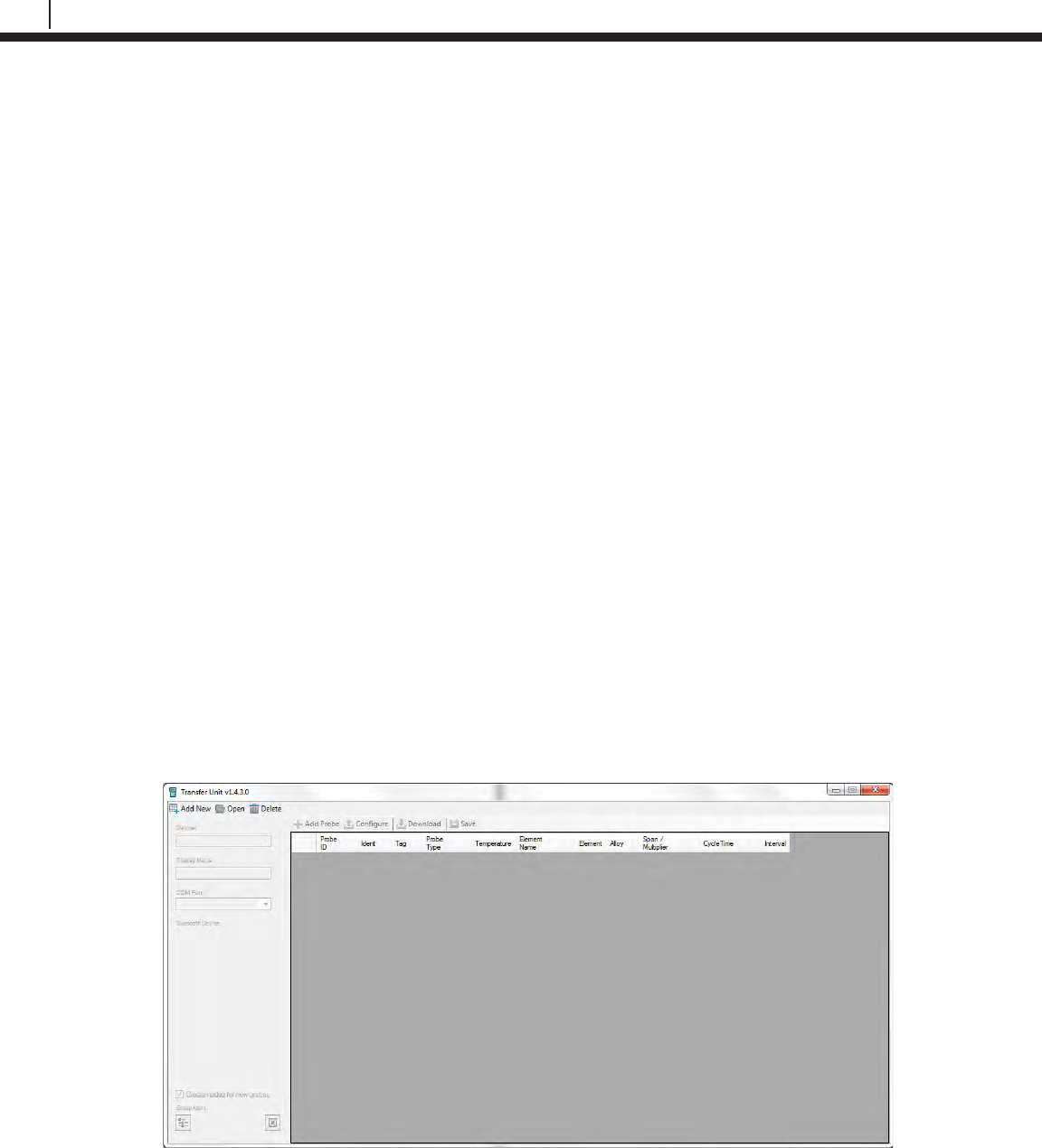
78
Transfer Readings from the Transfer Unit to Cosasco Data
Chapter 8
Transfer Readings from the Transfer
Unit to Cosasco Data
For maximum functionality and data management, all the data contained in the Transfer Unit may
be downloaded to a personal computer running Cosasco Data Corrosion Management Software.
The Cosasco Data software package is a flexible corrosion data management system that allows
integration of all corrosion monitoring parameters. Refer to the Cosasco Data Corrosion
Management Software documentation for installation, site setup, capabilities and other details.
Bluetooth Communication Requirements
In order to connect the Transfer Unit to the PC, the user will need a PC with Bluetooth capability
or a Bluetooth USB Adapter, which can be ordered through Cosasco (P/N 723763). The
recommended Bluetooth version is 2.1 + Enhanced Data Rate (EDR), but is compatible with
Bluetooth version 2.0, 1.2 and 1.1.
Create a New Group
Run Cosasco Data and from the Devices drop down list select Transfer Unit. A window will pop
up for the Transfer Unit Driver.
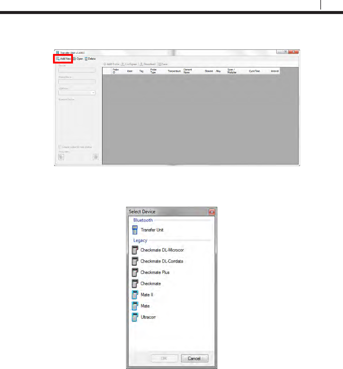
79
Bluetooth Suite
In the top right corner, select Add New to create a new group for the Transfer Unit.
The following window will pop up. Select Transfer Unit and select OK.
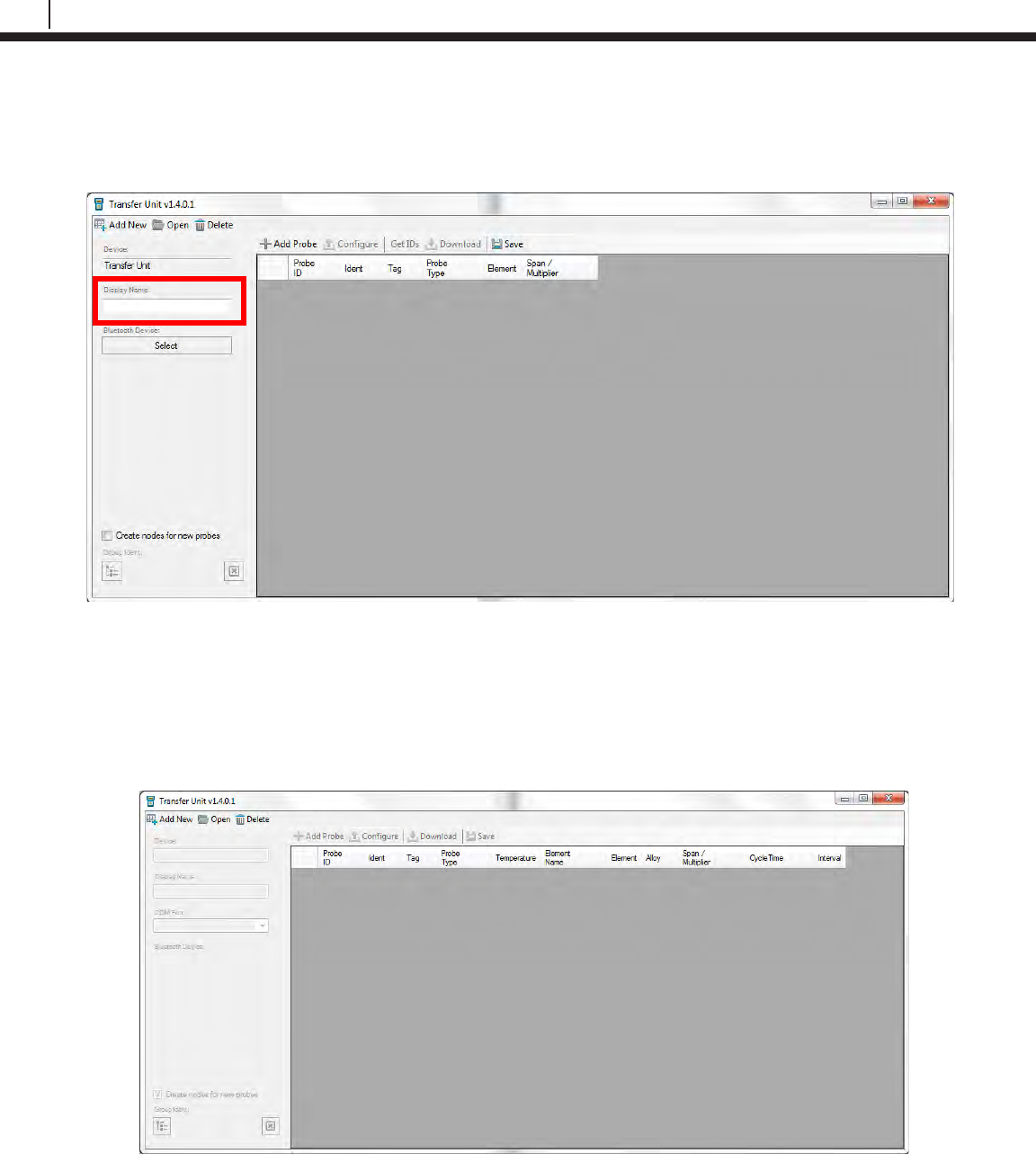
80
Transfer Readings from the Transfer Unit to Cosasco Data
After creating a new group, the Transfer Unit Driver window will now appear as below. Name the
group by typing the desired name into the Display Name box and click Save to save the changes
made.
Open a Group
Run Cosasco Data and from the Devices drop down list select Transfer Unit. A window will pop
up for the Transfer Unit Driver.
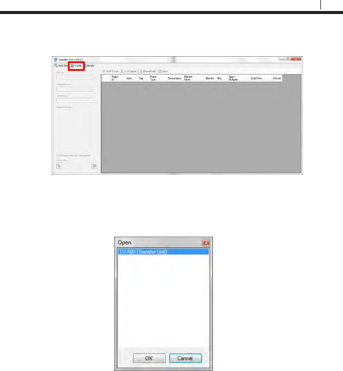
81
Bluetooth Suite
In the top right corner, select Open to open a previously created group for the Transfer Unit.
A screen will pop up containing a list of all of groups created for the Transfer Unit Driver with the
group name next to the group type which is in brackets. Select the group for the Transfer Unit
then select OK.
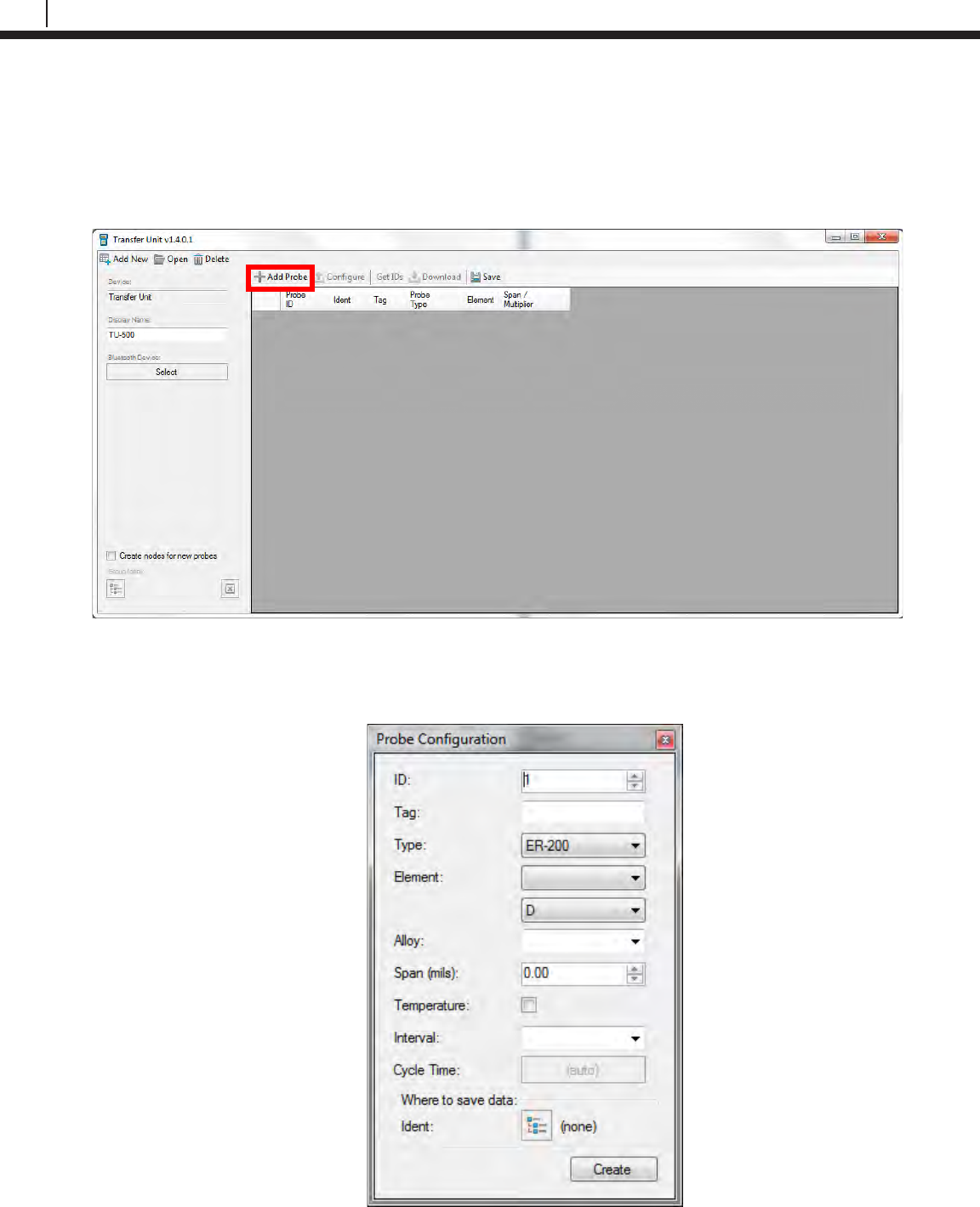
82
Transfer Readings from the Transfer Unit to Cosasco Data
Add a Probe through Cosasco Data
Run Cosasco Data and from the Devices drop down list select Transfer Unit. A window will pop
up for the Transfer Unit Driver. After creating a new group or opening a group, select Add Probe
to add a new probe to the list of probes for the Transfer Unit.
The following screen will appear. Enter the Probe ID, Tag Name and Probe Type. Depending on
the Probe Type chosen, enter the Element, Alloy, Span, if it’s a Temperature Probe, and
Interval in which it collects data.
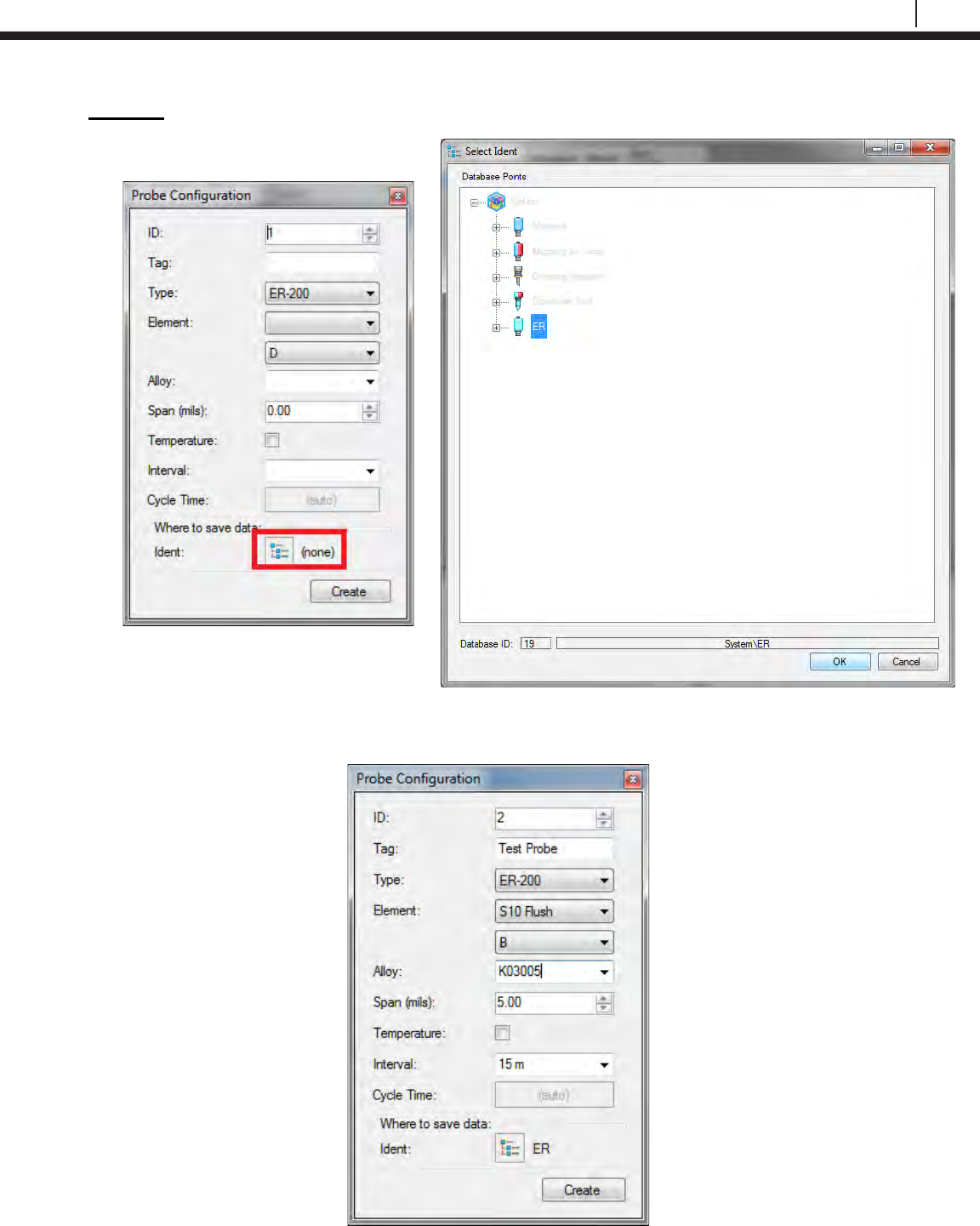
83
Bluetooth Suite
Optional: Click the box next to Ident and select a node to store the Probe’s Data to then click
OK.
Once the user has finished entering the details of the probe, select Create to add the probe to the
list. Then click Save to save the changes made to the Transfer Unit group.
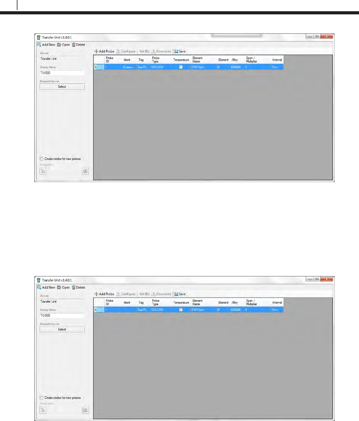
84
Transfer Readings from the Transfer Unit to Cosasco Data
Create Nodes for New Probes (Optional)
The Transfer Unit Driver gives the user the option to create new nodes in the Plant Layout for
Probe Data collected through the Transfer Unit. This removes the step of creating a node
manually and choosing a node to save the Probe Data to.
On the Transfer Unit Driver screen, select the checkbox next to Create nodes for new probes.
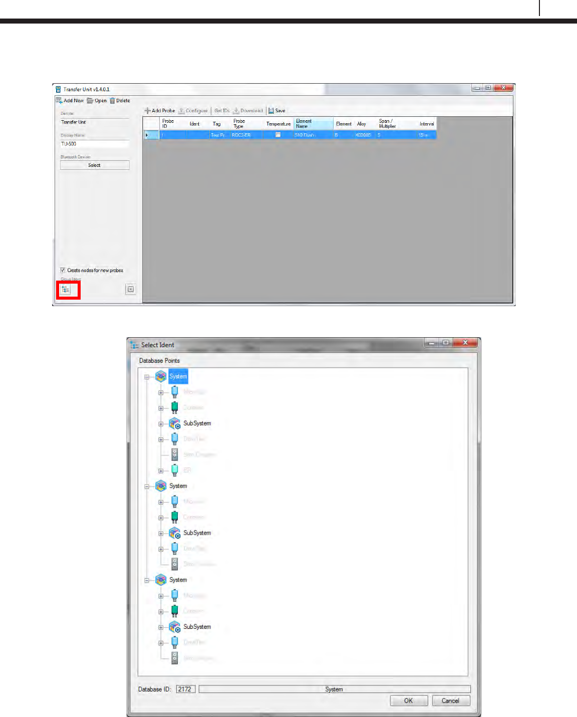
85
Bluetooth Suite
Click the icon under Group Ident and a window will appear with the Plant Layout within.
Select a System or Subsystem node for new probes to be created under and select OK.
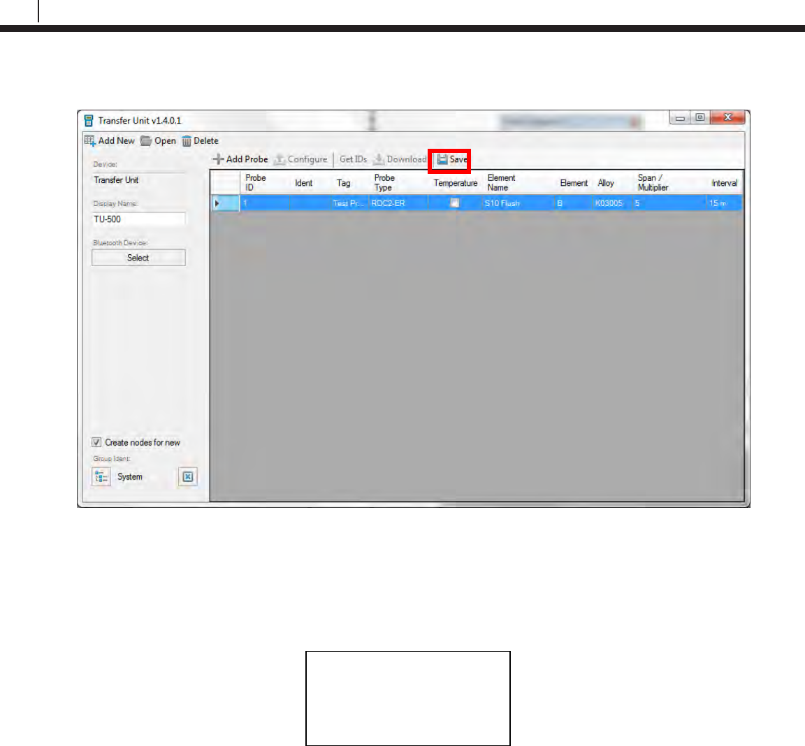
86
Transfer Readings from the Transfer Unit to Cosasco Data
Select Save to save the changes to where the new probes will be stored.
Connect Transfer Unit to PC
On the Transfer Unit select PC from the standby screen. It will show the following screen while
waiting to connect to the PC.
Waiting for PC
| Exit
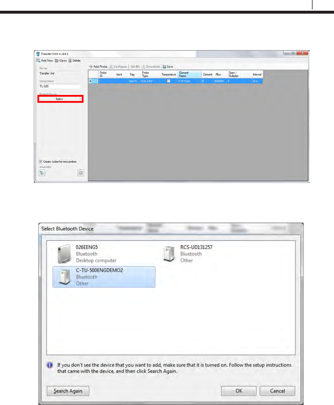
87
Bluetooth Suite
On the Transfer Unit Driver, click the box under Bluetooth Device.
A window will appear with possible Bluetooth devices the PC can connect to. Select the Transfer
Unit device then click OK.
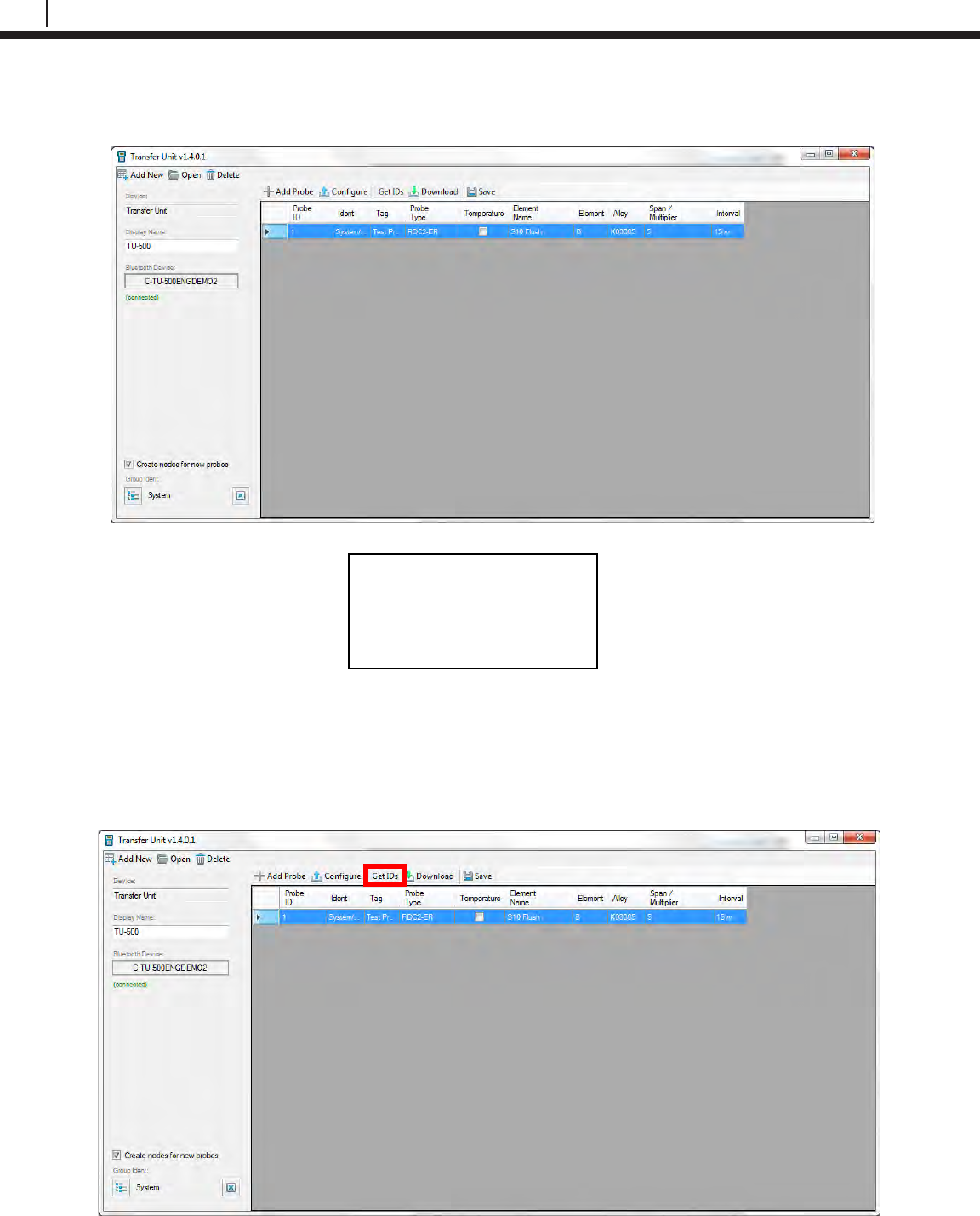
88
Transfer Readings from the Transfer Unit to Cosasco Data
The Transfer Unit Driver will now show the name of the Transfer Unit the PC is connected to and
connected in green underneath. The Transfer Unit will show the following screen.
Get ID’s from Transfer Unit
Once the Transfer Unit has connected to the PC, select Get IDs from the Transfer Unit Driver
window.
Waiting for Command
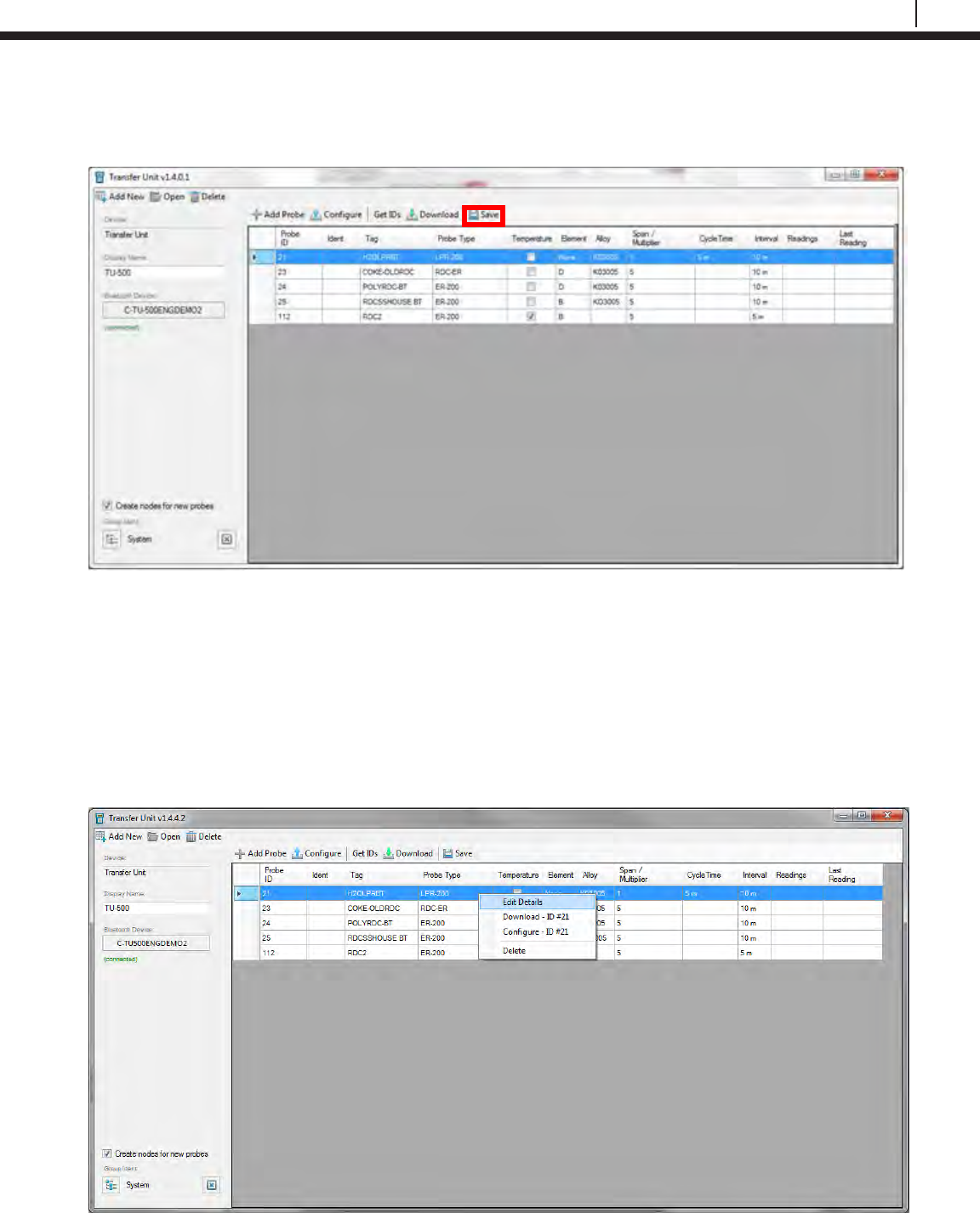
89
Bluetooth Suite
Once the transfer of the ID’s on the Transfer Unit to the PC is complete, the user will see a list of
all probes from the Transfer Unit. Click Save to save the list of probes from the Transfer Unit.
Configure Probes
WARNING: Changing the configuration of the Probes through the Transfer Unit Driver will erase
all stored data.
Configure Individual Probes
To change the configuration of a probe, right click it and select Edit Details.
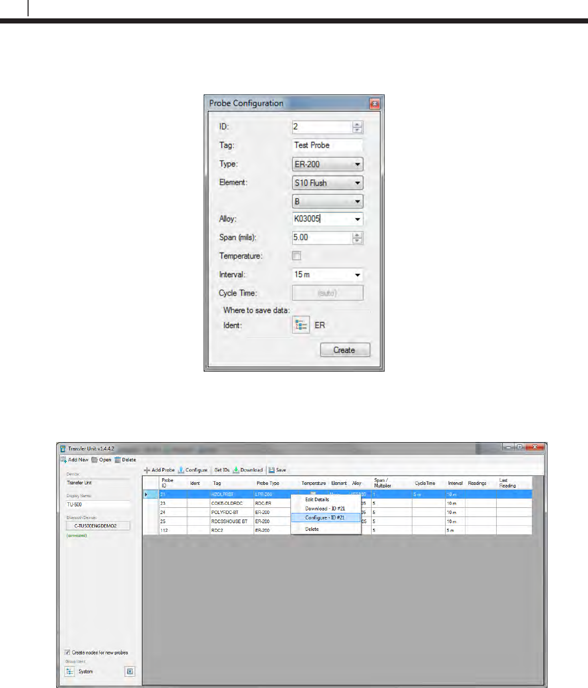
90
Transfer Readings from the Transfer Unit to Cosasco Data
On the window that appears, the user can change the Probe ID, Tag Name, Element, Alloy,
Span, if it’s a Temperature probe, Interval and Cycle Time depending on what type of probe it is.
Exit out of the screen once the user has finished changing the details of the probe. Right click the
probe and select Configure – ID to change the configuration of the probe on the Transfer Unit.
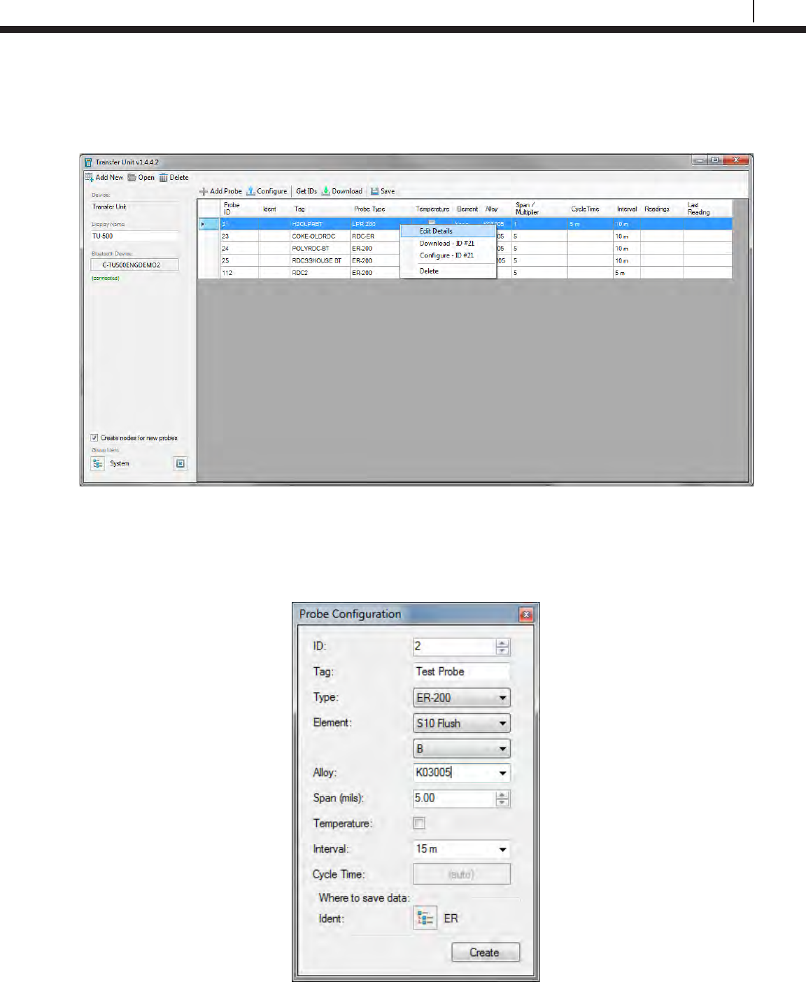
91
Bluetooth Suite
Configure All Probes
To change the configuration of a probe, right click it and select Edit Details.
On the window that appears, the user can change the Probe ID, Tag Name, Element, Alloy,
Span, if it’s a Temperature probe, Interval and Cycle Time depending on what type of probe it is.
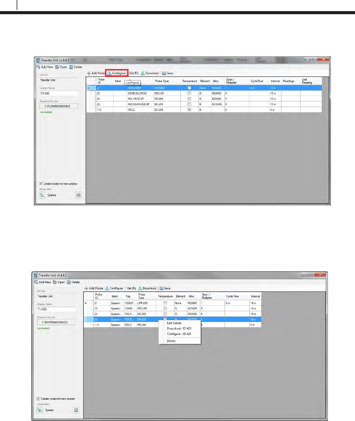
92
Transfer Readings from the Transfer Unit to Cosasco Data
Exit out of the screen. Once the user has finished changing the details of the probes, click
Configure. This will reconfigure all of the probes on the Transfer Unit.
Download Data
Download Individual Probe Data
To download a single probe’s data, right click a specific probe and select Download – ID.
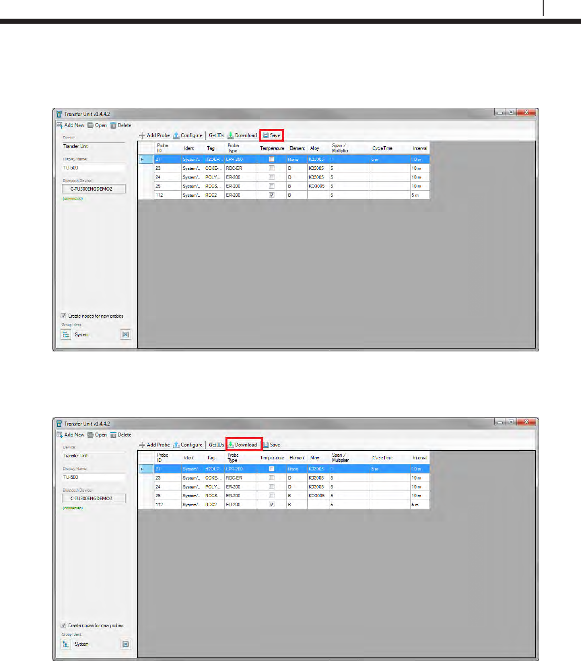
93
Bluetooth Suite
Once the data has finished downloading from the Transfer Unit to the PC the Transfer Unit Driver
will display the number of readings and the time of the last reading from the probe. Click Save to
save the downloaded data.
Download All Probe Data
To download data for all the probes on the Transfer Unit, select Download.
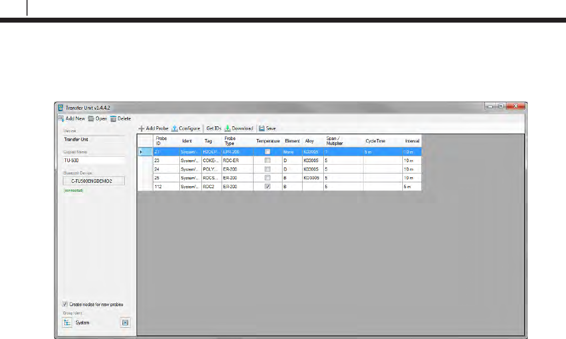
94
Transfer Readings from the Transfer Unit to Cosasco Data
Once the data has finished downloading from the Transfer Unit to the PC the Transfer Unit Driver
will display the number of readings and the time of the last reading from all of the probes on the
Transfer Unit. Click Save to save the downloaded data
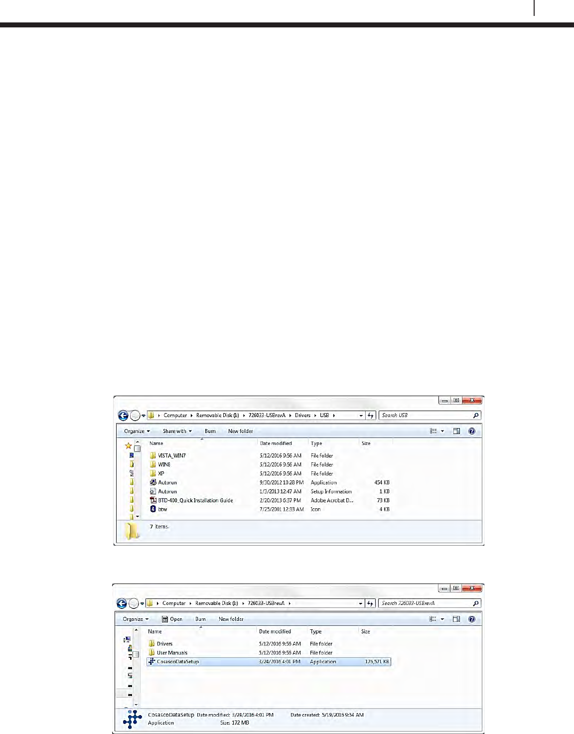
95
Bluetooth Suite
Appendix A
Update Device Firmware
TU-500 Firmware Update Instructions
These instructions describe the proper procedure for updating the firmware for the TU-500.
Required Equipment:
• TU-500 to be updated
• Kinivo Bluetooth USB
• Cosasco Bluetooth USB (P/N 726033)
• PC with USB port
WARNING:
This operation is intended to be done in a Non-Hazardous Area.
This process can take approximately 20 minutes to complete.
A close proximity of 3 feet or less is recommended between the Device and the PC.
DO NOT REMOVE BATTERIES UNTIL FIRMWARE UPDATE IS COMPLETED.
1. If not installed, install the drivers for the Kinivo USB device. The drivers are included on
the Cosasco Bluetooth USB.
2. If not installed, install the Device Firmware Update Software. The software is included on
the Cosasco Bluetooth USB device within the Cosasco Data Installation.
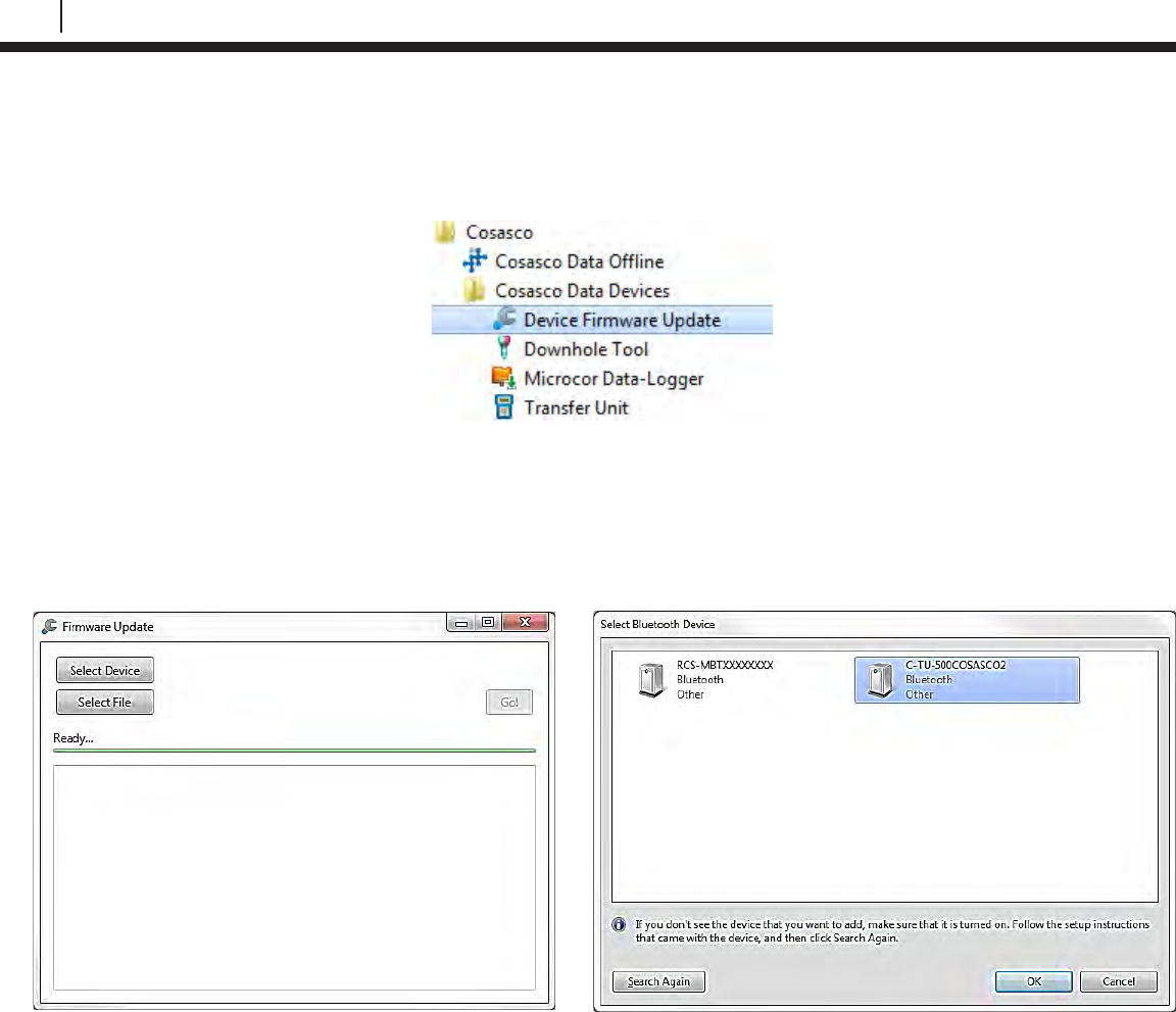
96
Update Device Firmware
3. Plug in the Kinivo Bluetooth USB device into the PC USB Port. Utilize the USB Ports on
the back of a Desktop PC where possible to help avoid errors.
4. Open the Device Firmware Update Software. This can typically be found in:
Start All Programs Cosasco Cosasco Data Devices Device Firmware Update
5. Turn on the TU-500 by using the Power Button and select PC on the TU-500 Main
Screen.
6. On the Device Firmware Update Window, click “Select Device”, select the TU-500 from
the window that has a matching serial number to the back of the device. For example,
C-TU500XXXXXXXX, where XXXXXXXX is the serial number for the device you are
updating. Then click “OK”.
7. On the Device Firmware Update Window, click “Select File”, open the .rcsfirmware version
you are trying to apply to the TU-500. EX. “101181 TU-500boot V1_XX.rcsfirmware”
8. If more than 3 minutes have passed since the TU-500 PC mode was selected, you may
have to select it again. The TU-500 goes into a low power mode to conserve battery
power after 3 minutes of no activity.
9. Click “Go!”.
10. The Device Firmware Update Application should now attempt to connect to the TU-500.
The TU-500 will then display “PRODUCTION TEST” then “BOOTLOAD MODE”. The
Device Firmware Update Application will have sent the message configuring the device for
boot-load mode. If an error occurs here, retry by clicking “Go!”. Once the Device Firmware
Application has begun, a progress bar will proceed across the screen. After the first
progress bar is completed a 2nd progress bar saying “verifying” will proceed across the
screen.
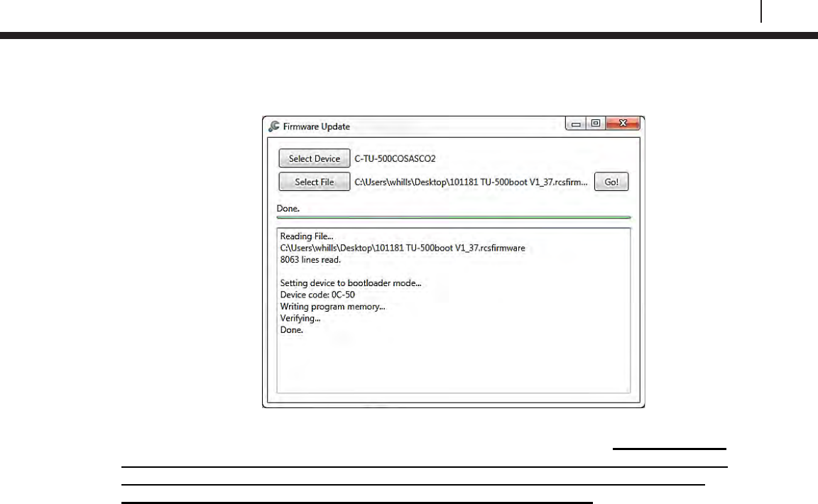
97
Bluetooth Suite
11. Wait until the Device Firmware Update Window displays “Done”. This can take about 15
minutes to complete.
12. Remove batteries from the TU-500 then reinsert them into the TU-500. NOTE: DO NOT
REMOVE BATTERIES UNTIL FIRMWARE UPDATE IS COMPLETED. IF BATTERIES
ARE REMOVED BEFORE THE FIRMWARE UPDATE IS DONE THE TU-500 WILL
APPEAR BROKEN WITH BLACK LINES ACROSS THE SCREEN.
13. Power on the TU-500 using the Power Button. The screen will show “Setting Baud to 57k”
then proceed to the main screen. This indicates the device is ready for use. Note: the
firmware version in the upper right of the main screen should have now changed to
the intended version being updated.
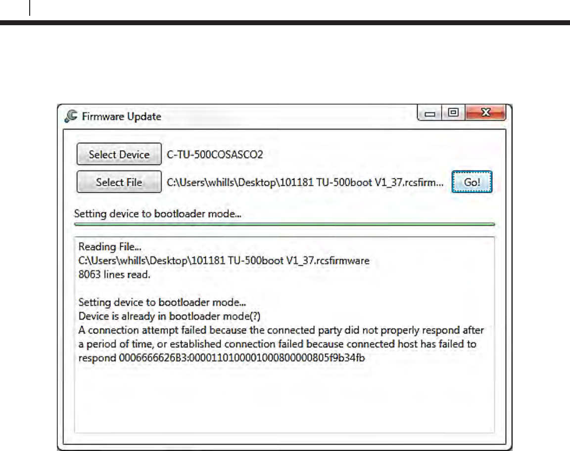
98
Update Device Firmware
Troubleshooting
If you receive a similar screen to the following:
This can be caused by:
• Wrong Device Selected
• TU-500 is off
• TU-500 not set to PC mode
If this occurs start again from step 5.
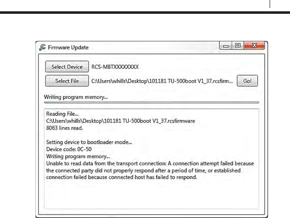
99
Bluetooth Suite
If you receive a similar screen to the following:
This can be caused by:
• The TU-500 out of range
• Too many devices drawing power from USB port
• Bad USB port on the PC
If this occurs and the front USB ports are being used, unplug any un-needed peripherals attached
to the front USB ports. This will optimize performance of the Kinivo USB device. On some PCs, it
has been shown to negatively affect the Bluetooth range with multiple devices plugged into the
front USB ports. Next, start again from Step 5.
If this occurs and the front USB ports are not being used, start again from Step 5.

100
Update Device Firmware
If the screen on the TU-500 appears as the following:
TU-500 Batteries Removed too soon error screen
This can be caused by:
• Batteries removed before update process completed
• Low Batteries
If this occurs start again from Step 5. If this continues to occur replace batteries and proceed from
Step 5.
■■■■■■■■■■■■■■■■■■■■■
■■■■■■■■■■■■■■■■■■■■■
■■■■■■■■■■■■■■■■■■■■■
■■■■■■■■■■■■■■■■■■■■■
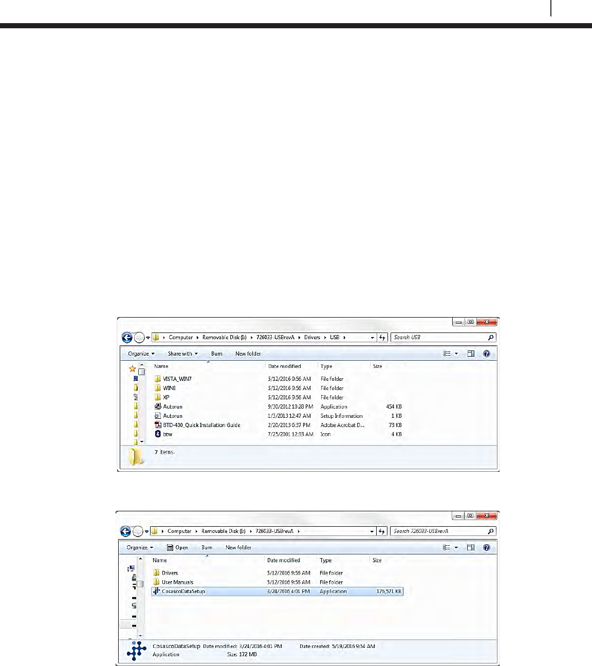
101
Bluetooth Suite
ER-100, LPR-100, ER-200, and LPR-200 Firmware Update Instructions
These instructions describe the proper procedure for updating the firmware for the ER-100, LPR-
100, ER-200, and LPR-200.
Required Equipment:
• Device to be updated
• Kinivo Bluetooth USB
• Cosasco Bluetooth USB (P/N 726033)
• PC with USB port
WARNING:
This operation is intended to be done in a Non-Hazardous Area.
This process can take approximately 20 minutes to complete.
A close proximity of 3 feet or less is recommended between the Device and the PC.
DO NOT REMOVE BATTERIES UNTIL FIRMWARE UPDATE IS COMPLETED.
1. If not installed, install the drivers for the Kinivo USB device. The drivers are included on
the Cosasco Bluetooth USB.
2. If not installed, install the Device Firmware Update Software. The software is included on
the Cosasco Bluetooth USB device within the Cosasco Data Installation.
3. Plug in the Kinivo Bluetooth USB device into the PC USB Port. Utilize the USB Ports on
the back of a Desktop PC where possible to help avoid errors.
4. Open the Device Firmware Update Software. This can typically be found in:
Start All Programs Cosasco Cosasco Data Devices Device Firmware Update
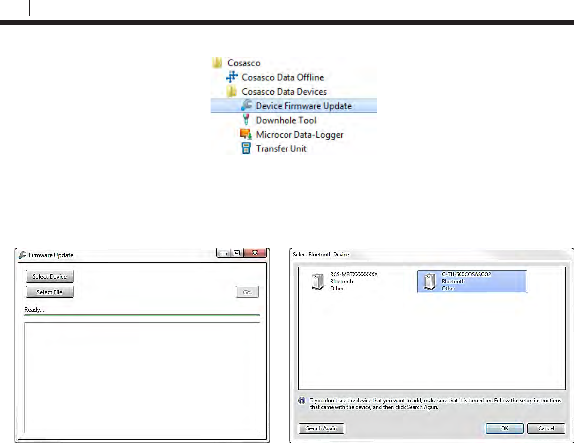
102
Update Device Firmware
5. Turn on the Device by using the Power Button for ER-100 and LPR-100, and by power
cycling the battery for the ER-200 and LPR-200.
6. On the Device Firmware Update Window, click “Select Device”, select the Device from the
window that has a matching serial number to the back of the device. For example,
C-ER-100XXXXXXXX, where XXXXXXXX is the serial number for the device you are
updating. Then click “OK”.
7. On the Device Firmware Update Window, click “Select File”, open the .rcsfirmware version
you are trying to apply to the device. EX. “101180 ER-100boot_V1_X.rcsfirmware”
8. If more than 3 minutes have passed since the Device was powered/power cycled, you
may have to power cycle it again. The Devices go into a low power mode to conserve
batteries after 3 minutes of no activity.
9. Click “Go!”.
10. The Device Firmware Application should now attempt to connect to the Device. The
Device LED will be a solid green light and then go out. The Device Firmware Application
will have sent the message configuring the device for boot-load mode. If an error occurs
here, retry by clicking “Go!”. Once the Device Firmware Application has begun, a progress
bar will proceed across the screen. After the first progress bar is completed a 2nd progress
bar saying “verifying” will proceed across the screen.
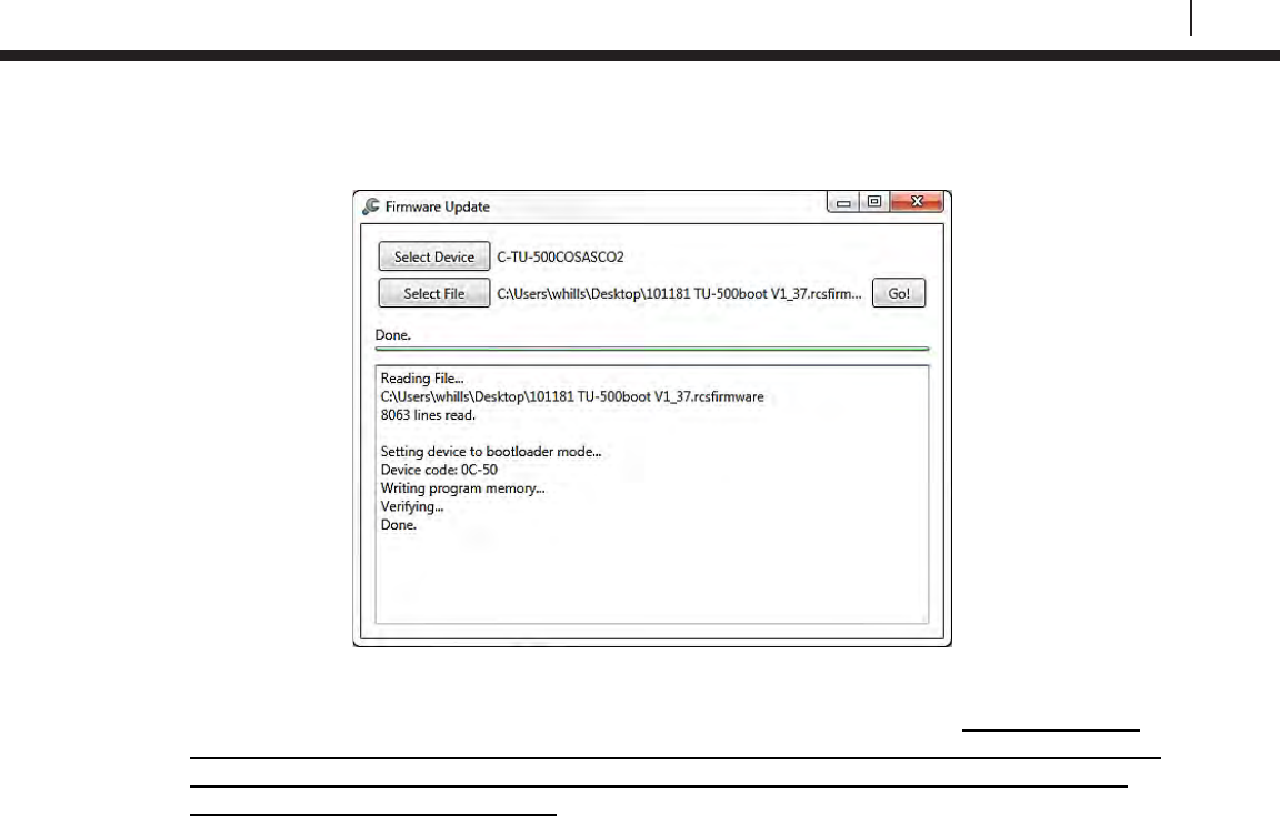
103
Bluetooth Suite
11. Wait until the Device Firmware Update Application screen displays “Done”. This can take
about 15 minutes.
12. For the ER-100 and LPR-100, remove the batteries from the Device then reinsert them
into the Device. For the ER-200 and LPR-200, power cycle the battery. NOTE: DO NOT
REMOVE BATTERIES UNTIL FIRMWARE UPDATE IS COMPLETED. REMOVING THE
BATTERIES BEFORE THE FIRMWARE UPDATE IS COMPLETE WILL CAUSE THE
DEVICE TO APPEAR BROKEN. If this occurs repeat the steps starting at step 6.
13. Power on the Device using the Power Button. The LED will be flashing green. This
indicates the device is ready for use/configuration.

104
Update Device Firmware
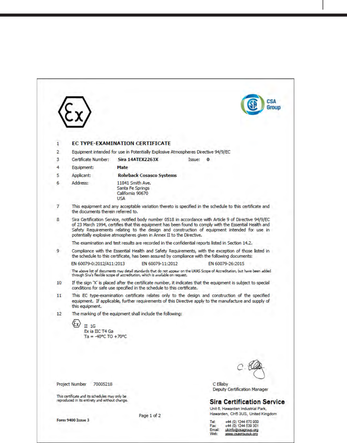
105
Bluetooth Suite
Appendix B
EC Type Examination Certificates
Transfer Unit
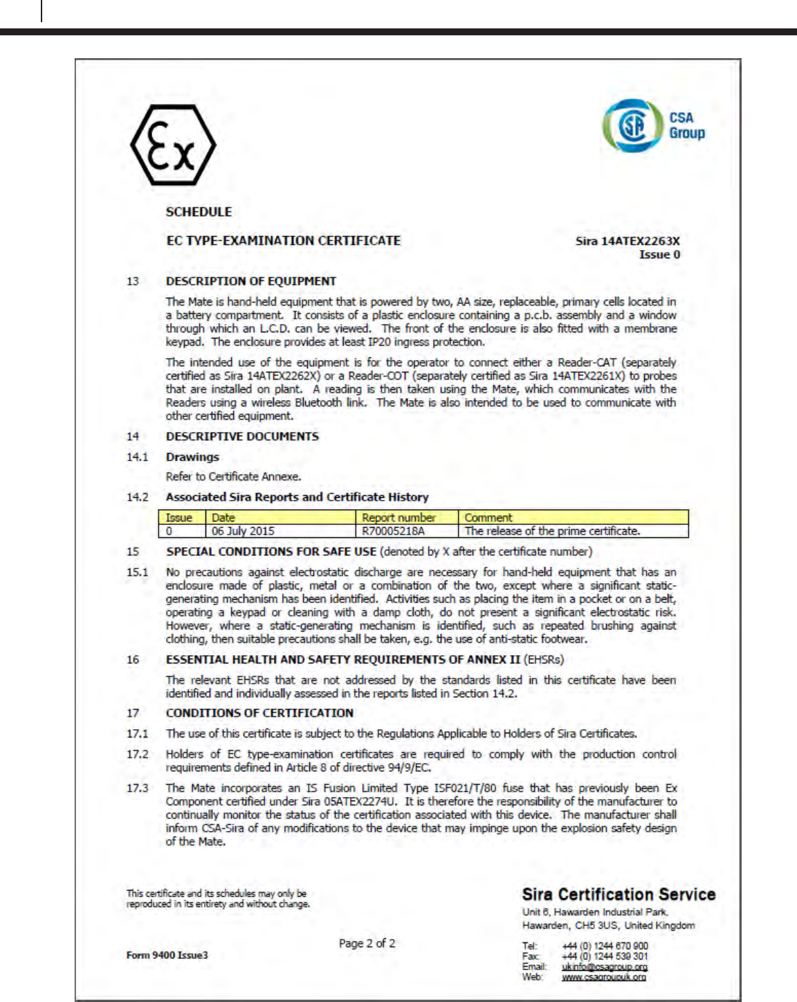
106
EC Type Examination Certificates
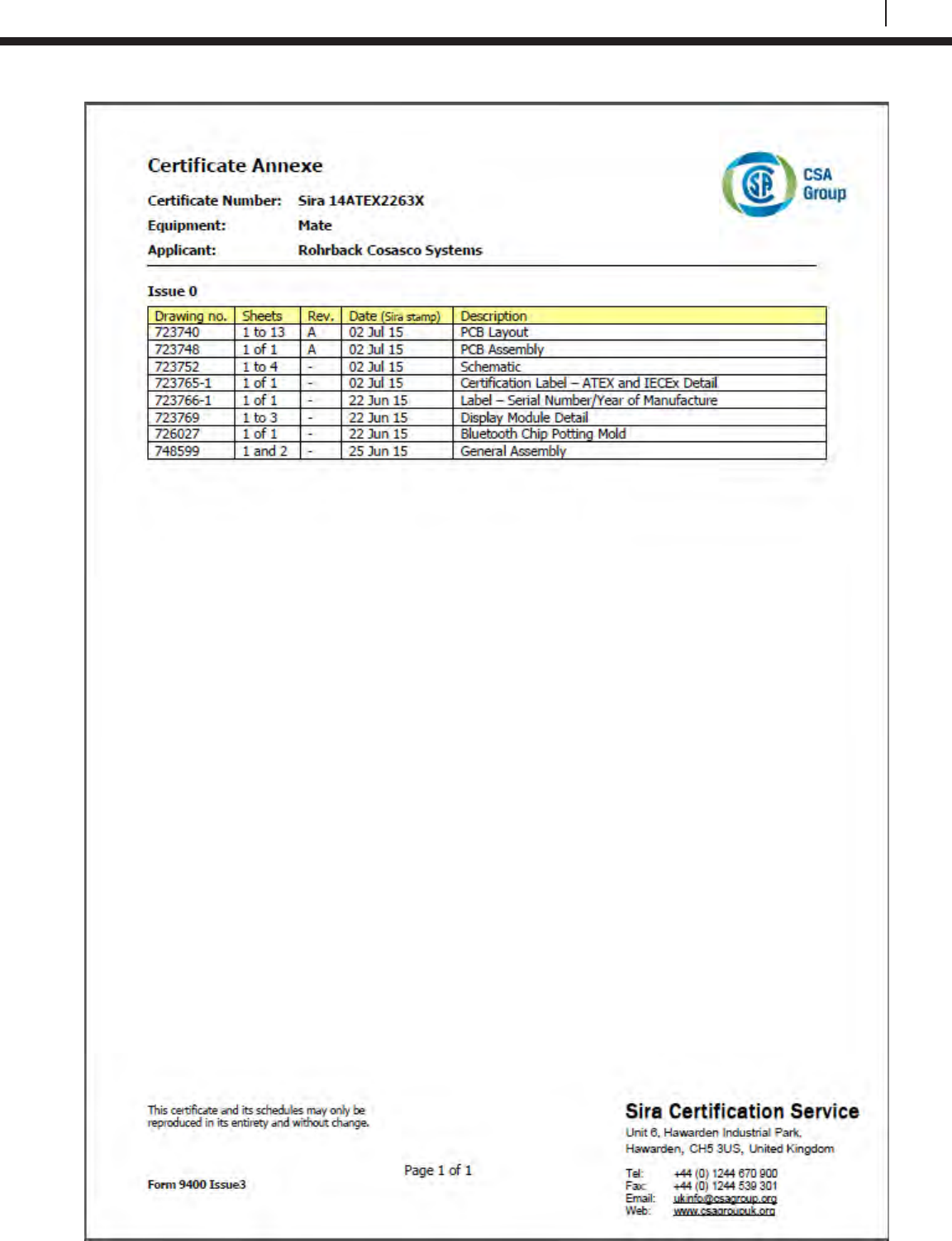
107
Bluetooth Suite
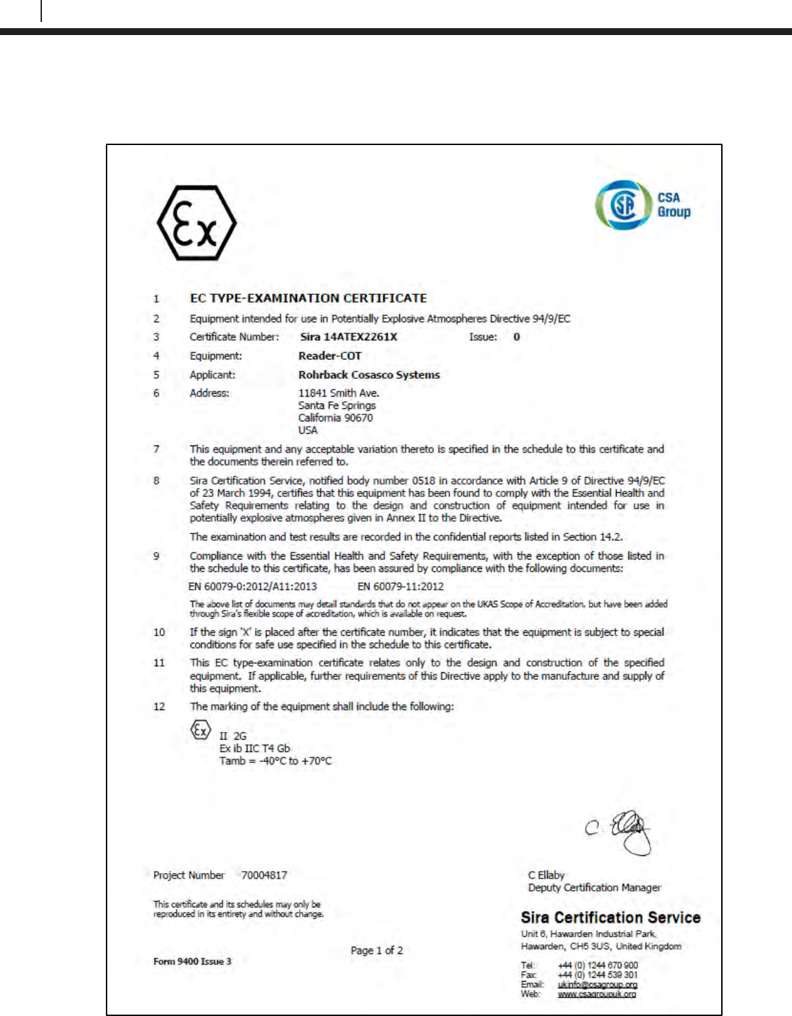
108
EC Type Examination Certificates
ER Probe Reader
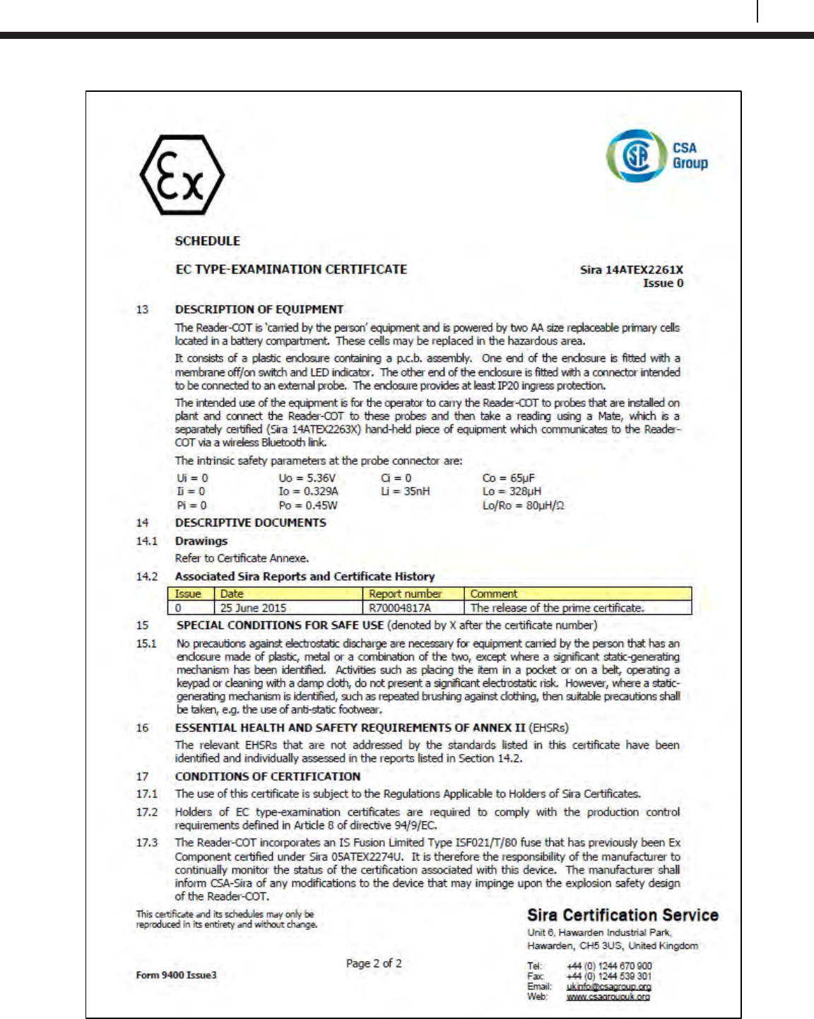
109
Bluetooth Suite
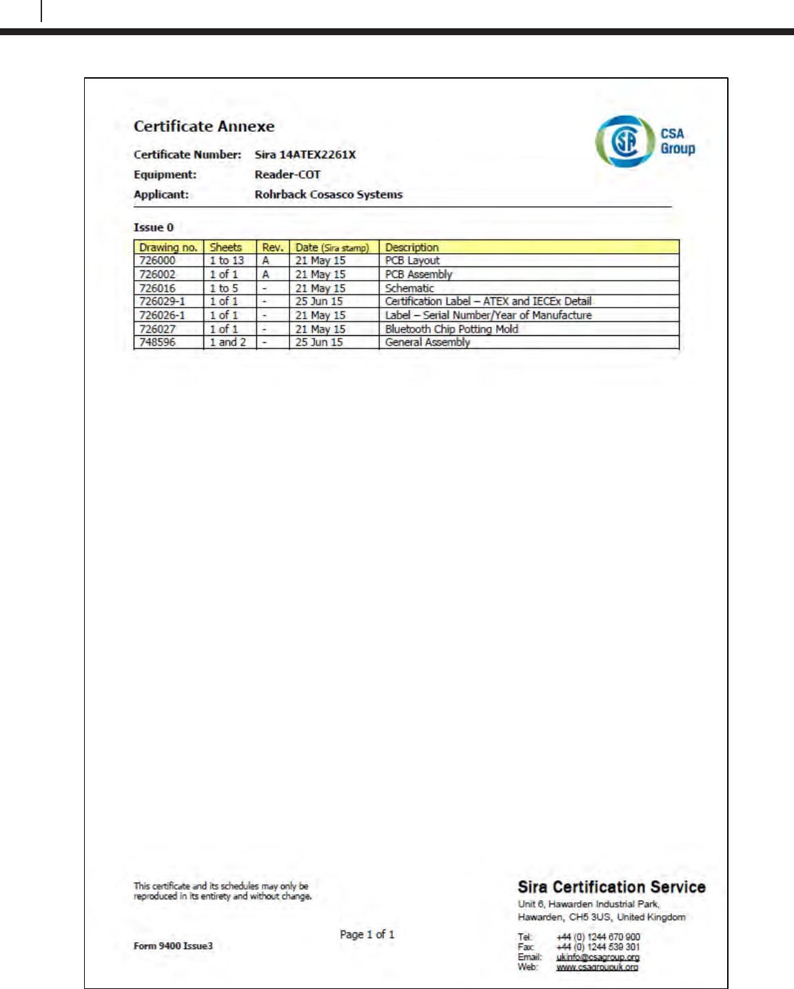
110
EC Type Examination Certificates
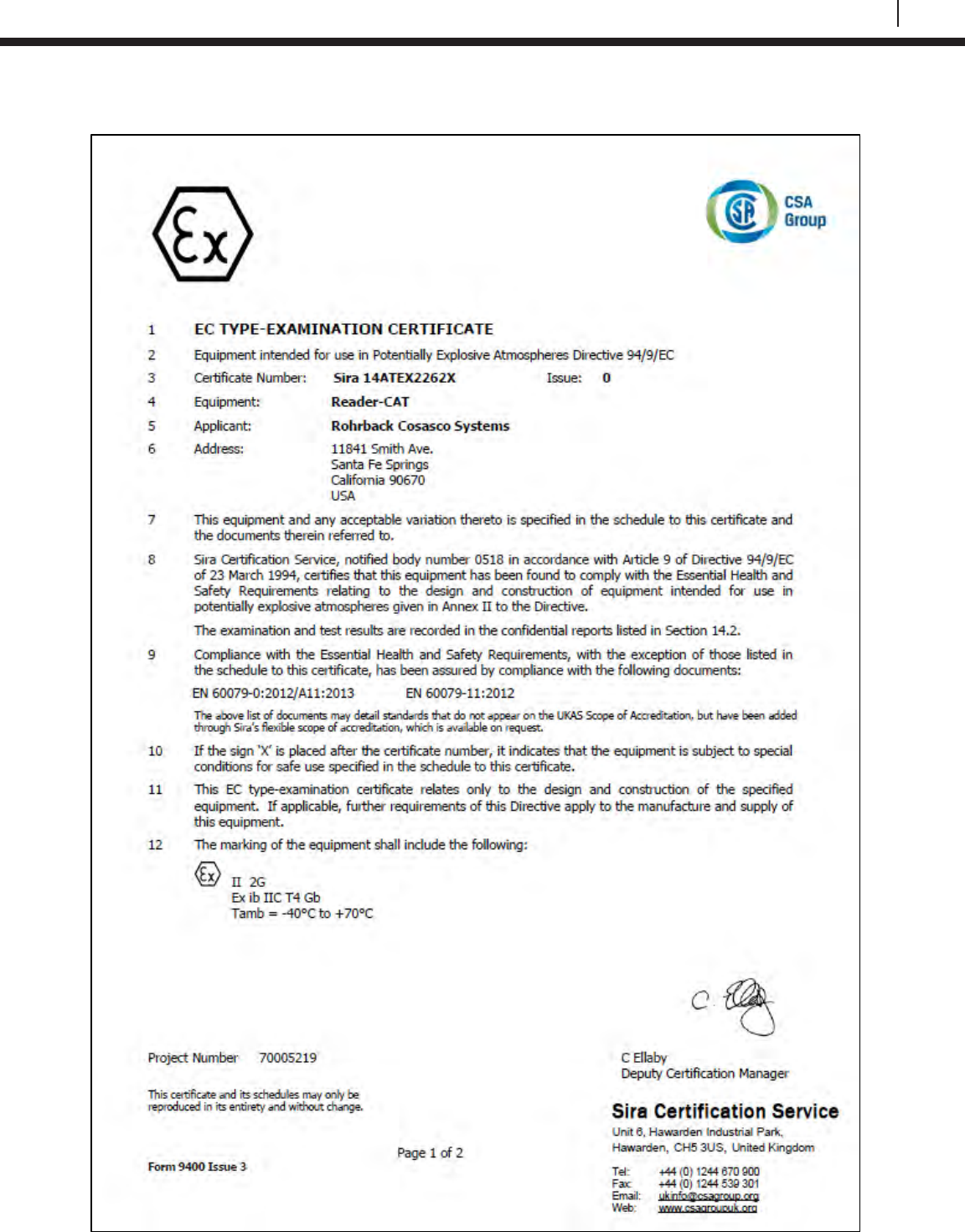
111
Bluetooth Suite
LPR Probe Reader
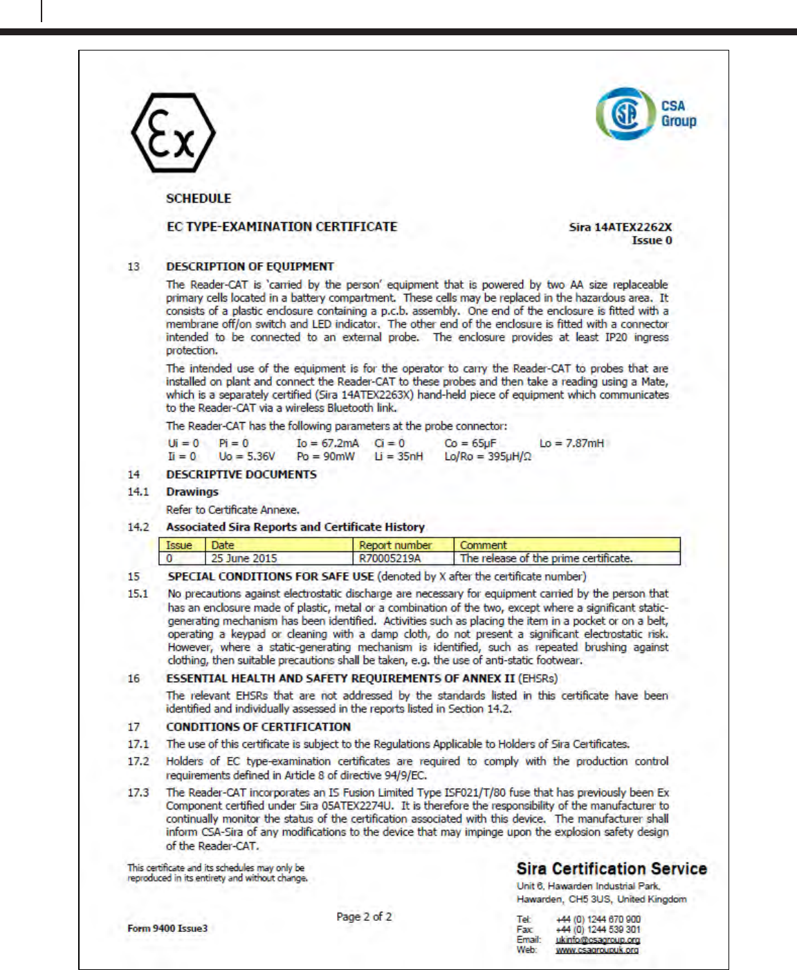
112
EC Type Examination Certificates
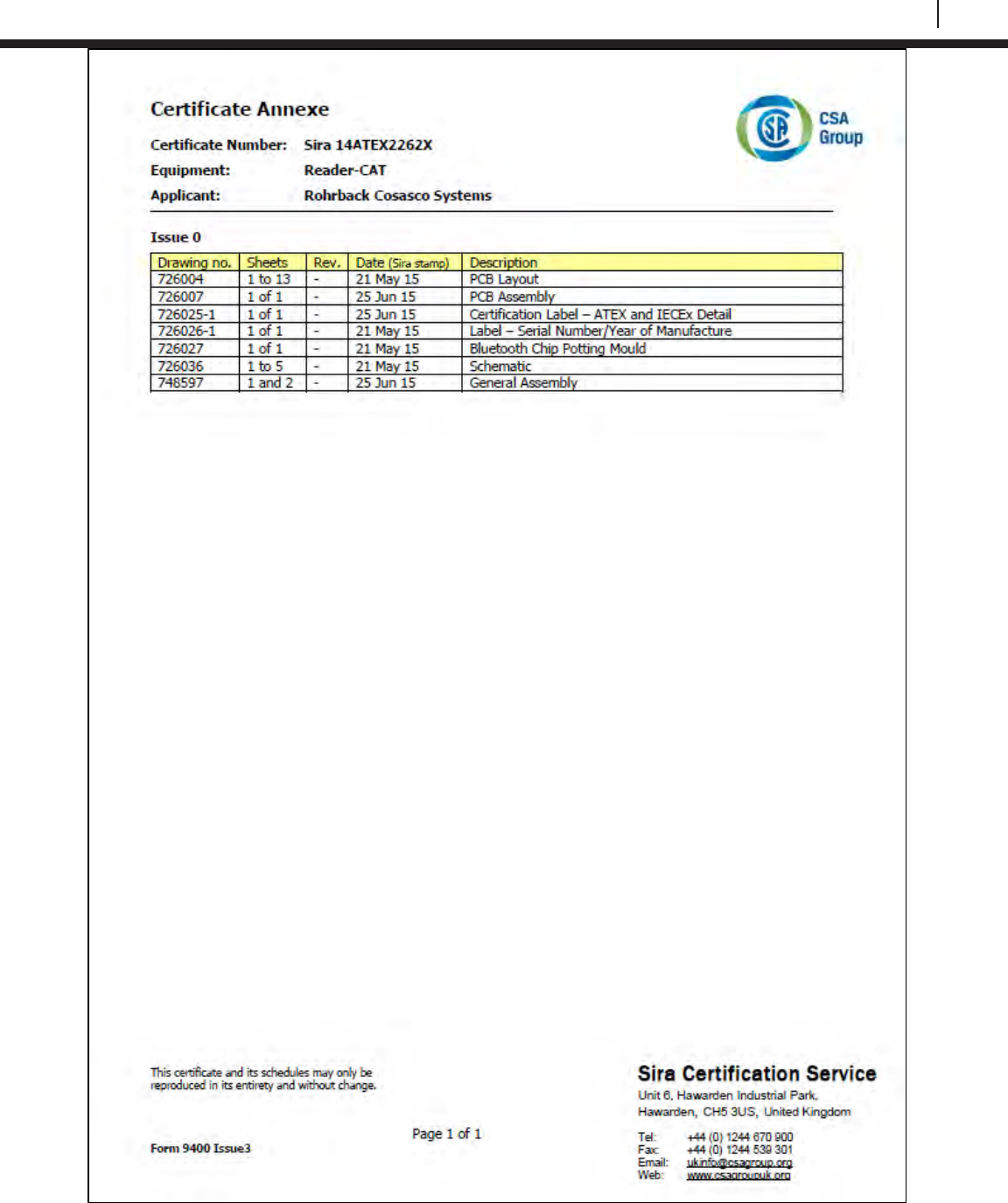
113
Bluetooth Suite
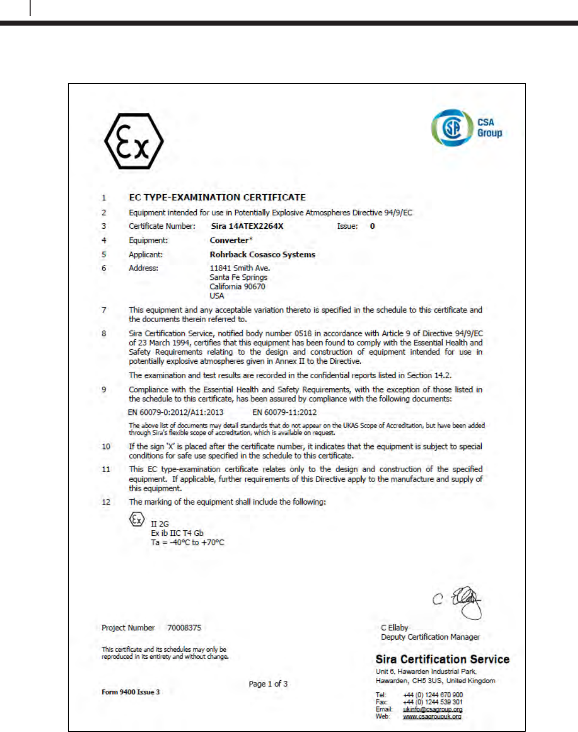
114
EC Type Examination Certificates
Legacy Converter
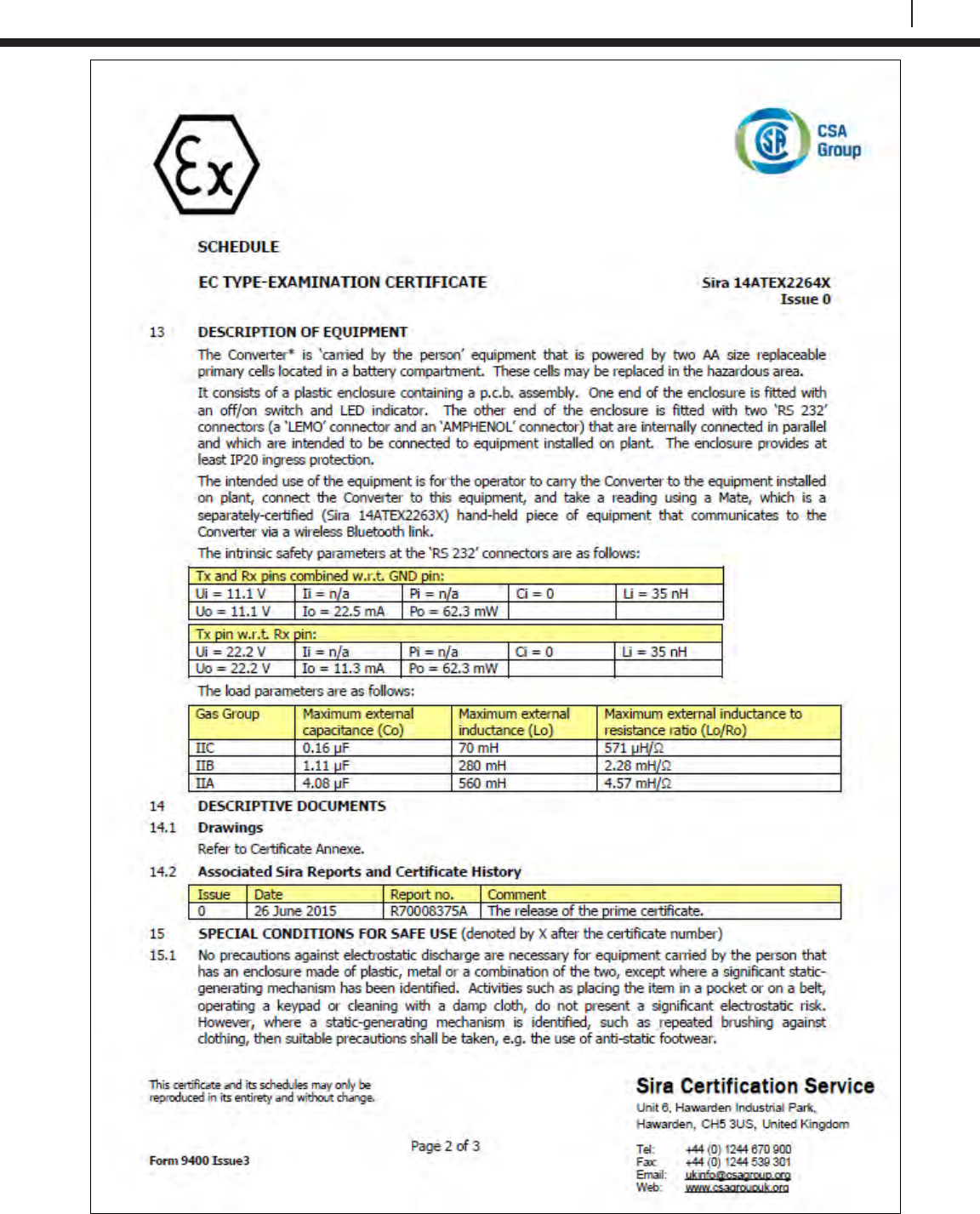
115
Bluetooth Suite
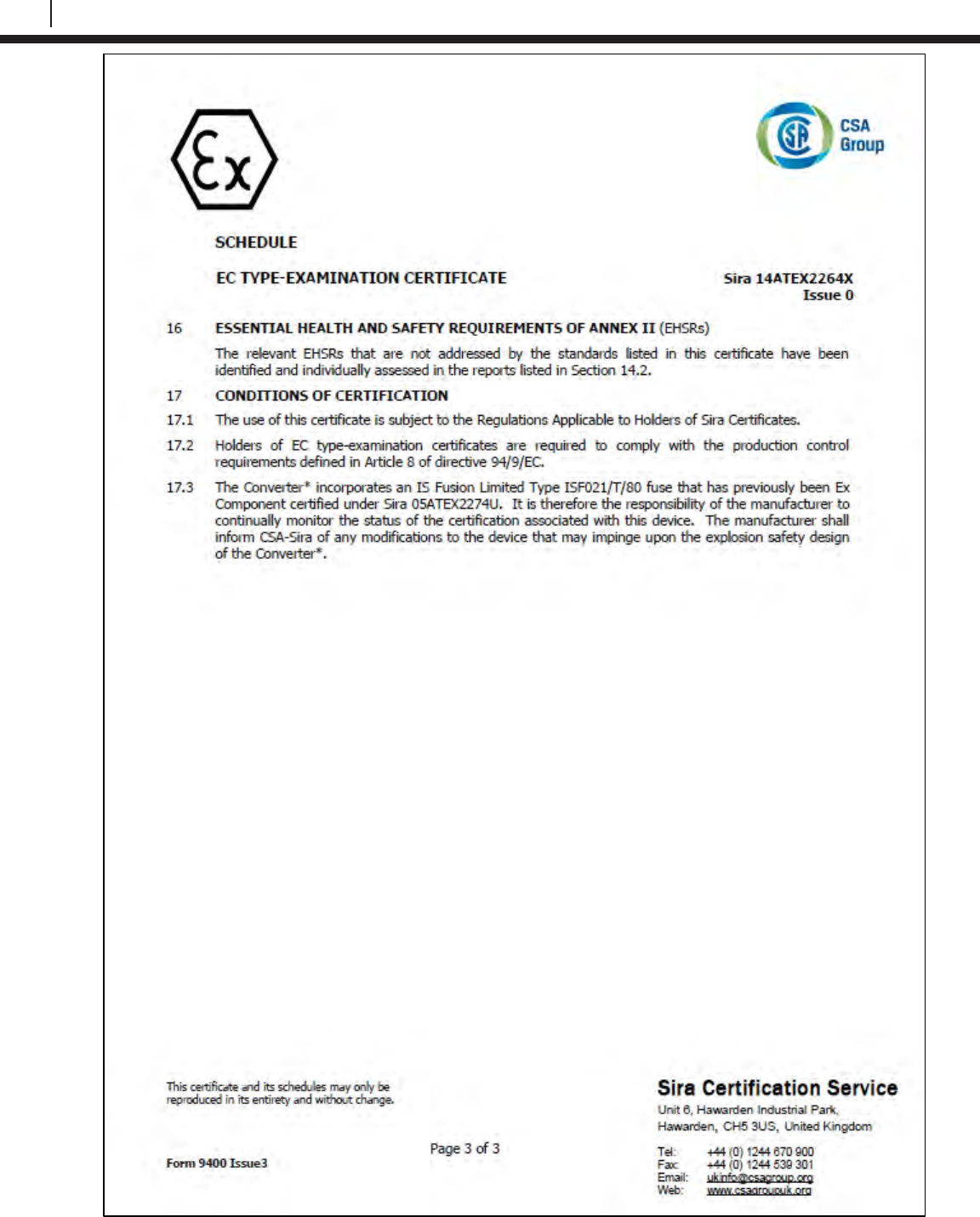
116
EC Type Examination Certificates
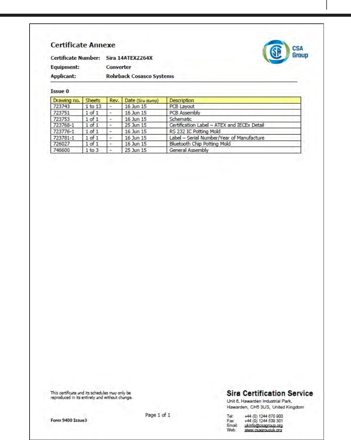
117
Bluetooth Suite
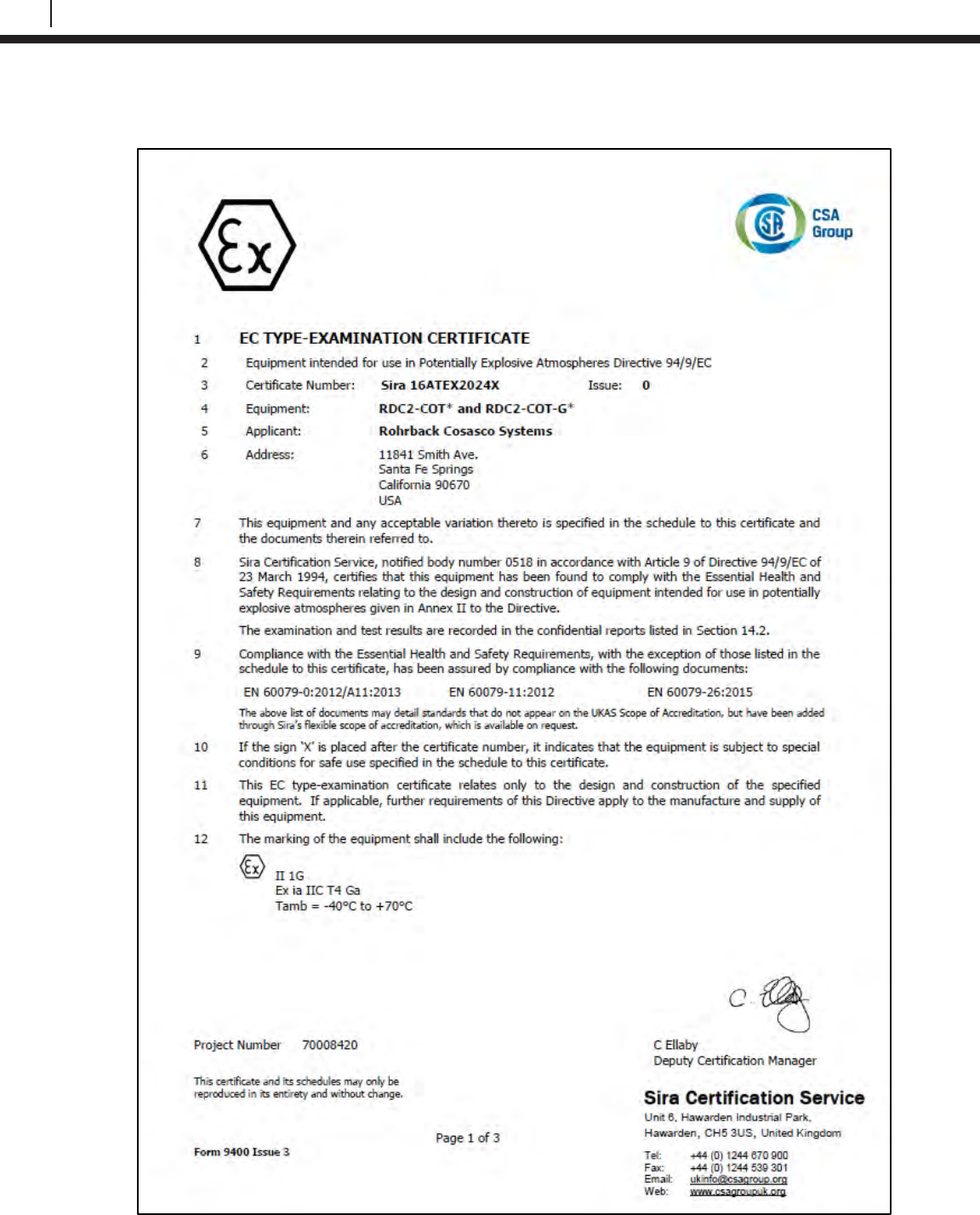
118
EC Type Examination Certificates
ER Datalogger
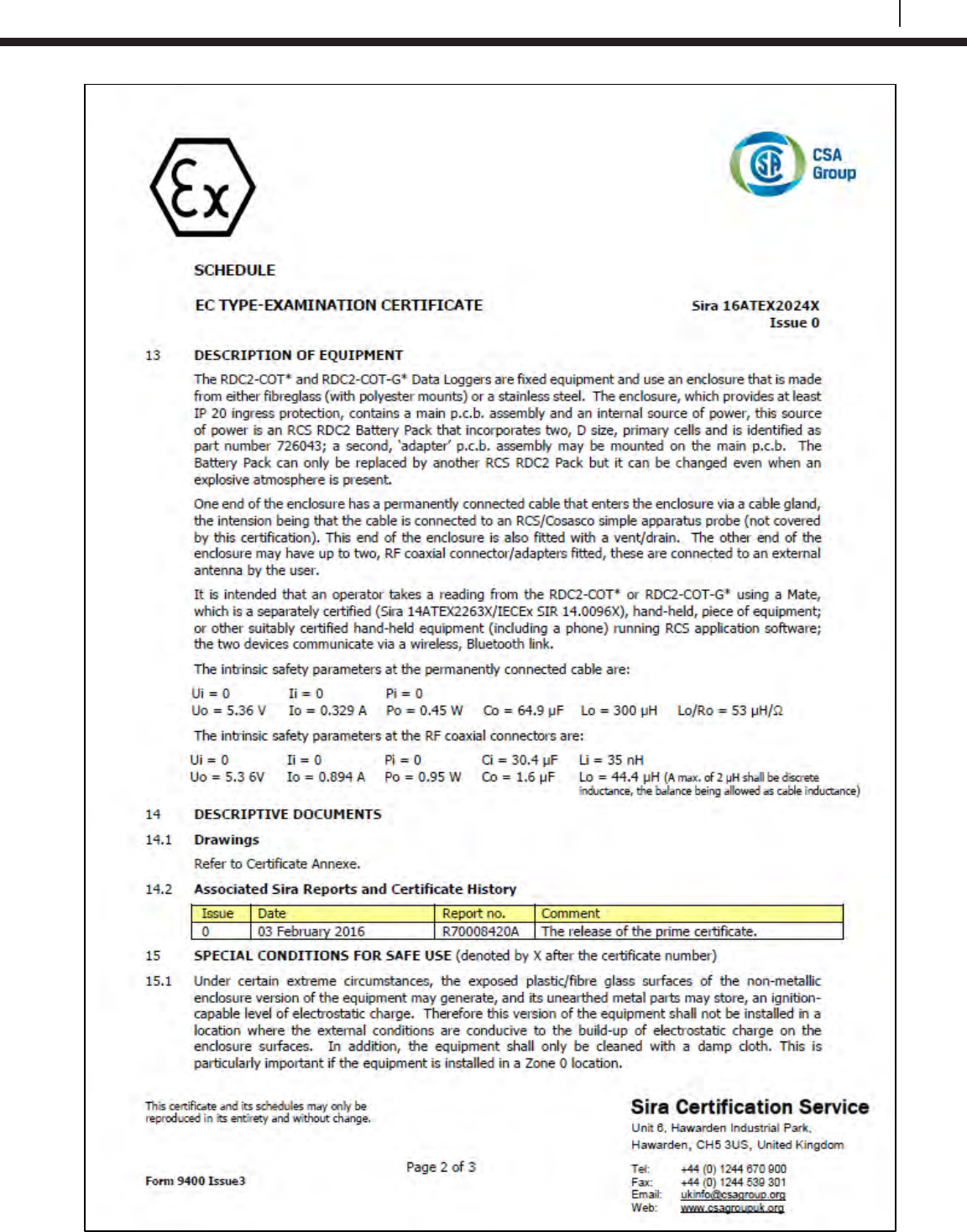
119
Bluetooth Suite
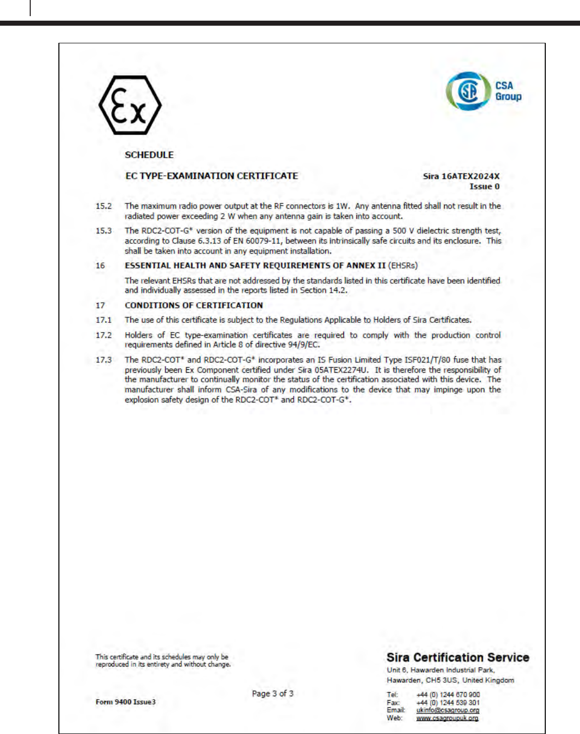
120
EC Type Examination Certificates
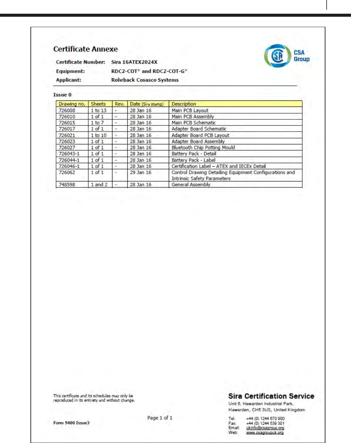
121
Bluetooth Suite
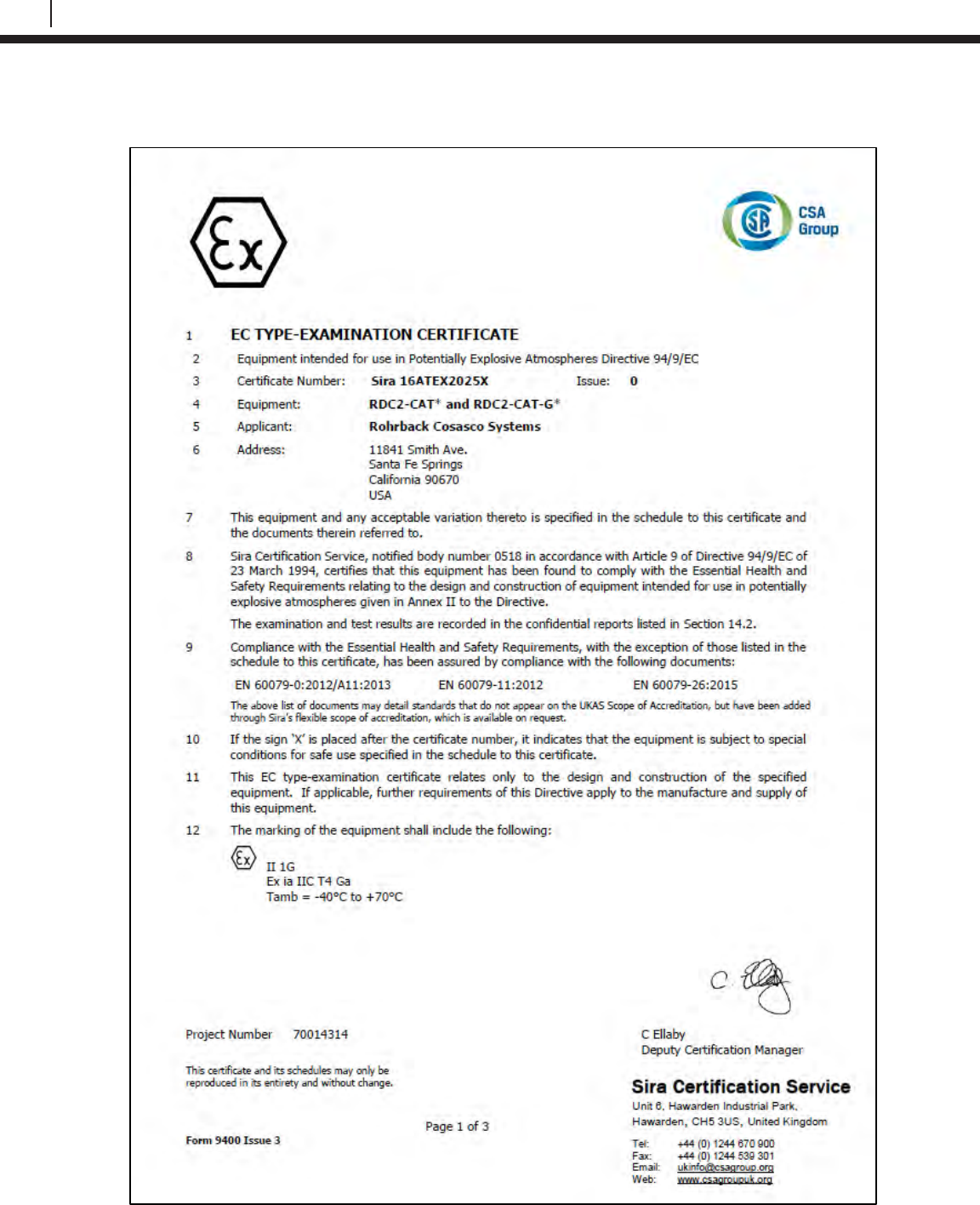
122
EC Type Examination Certificates
LPR Datalogger
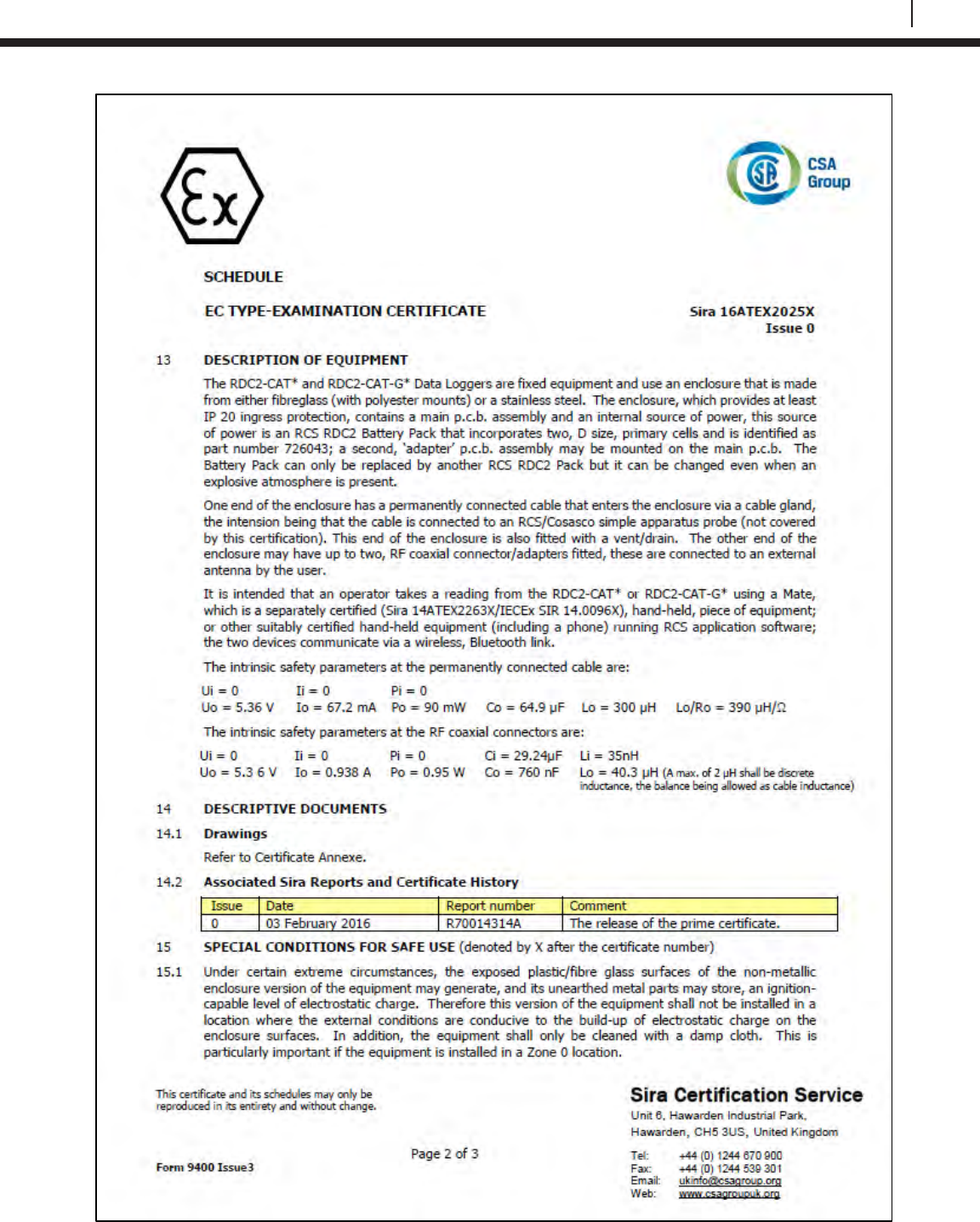
123
Bluetooth Suite
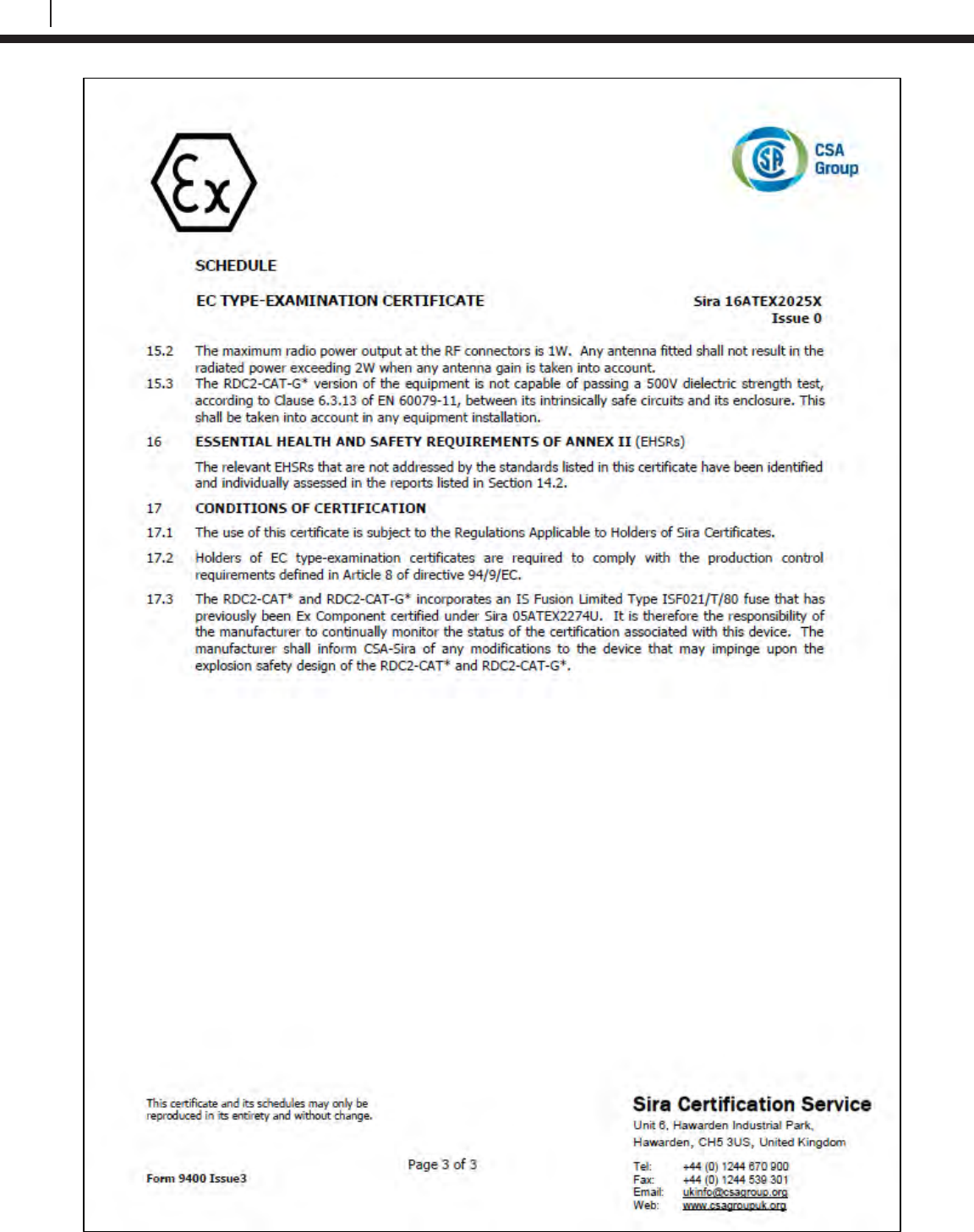
124
EC Type Examination Certificates
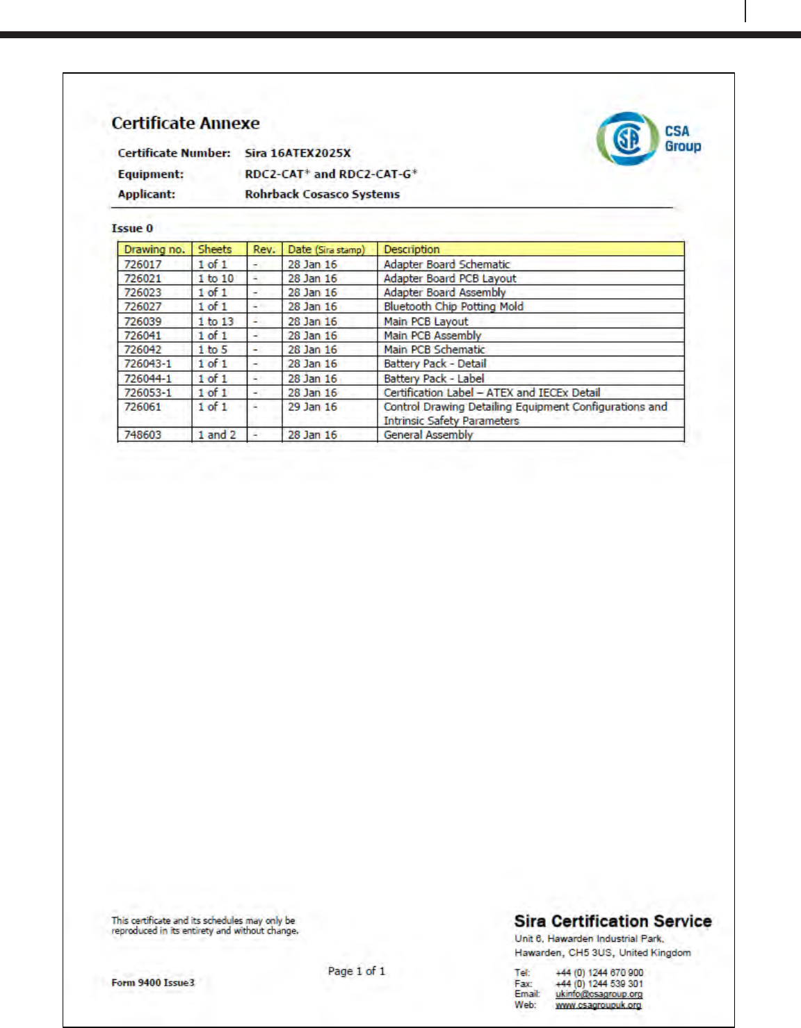
125
Bluetooth Suite
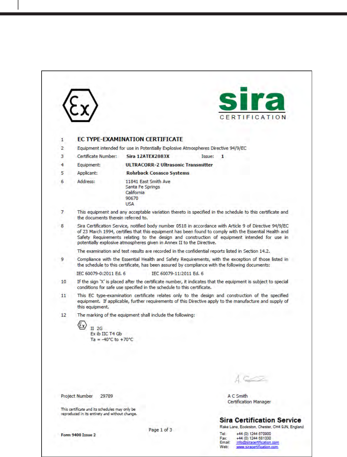
126
EC Type Examination Certificates
Ultracorr 2
UST2 Ultrasonic Transmitter
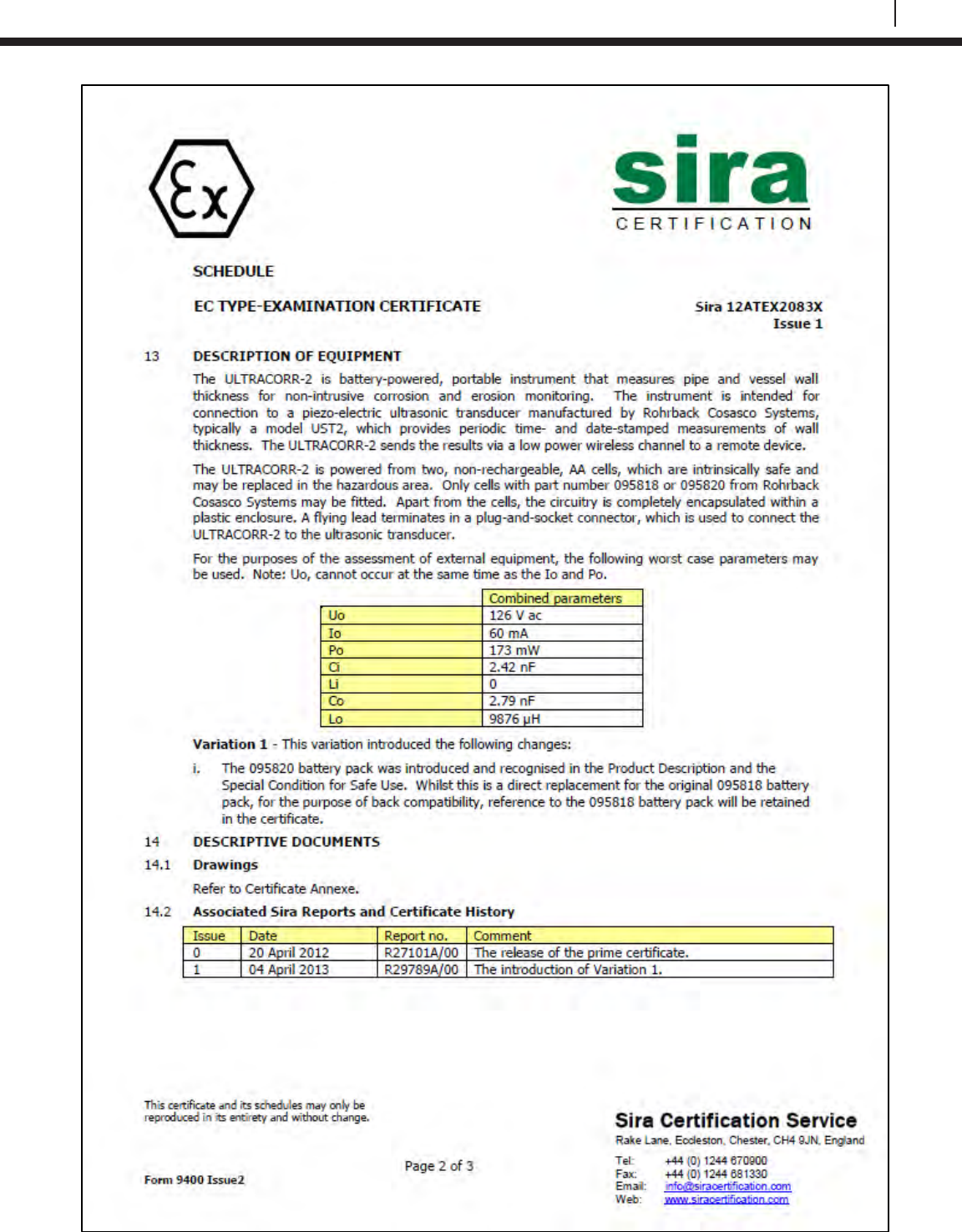
127
Bluetooth Suite
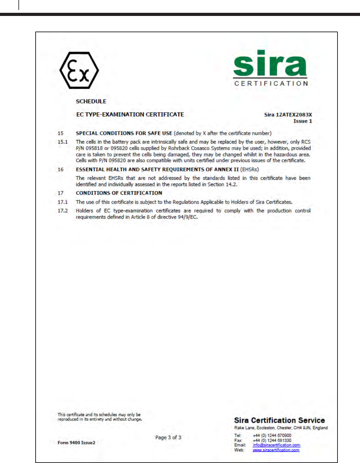
128
EC Type Examination Certificates
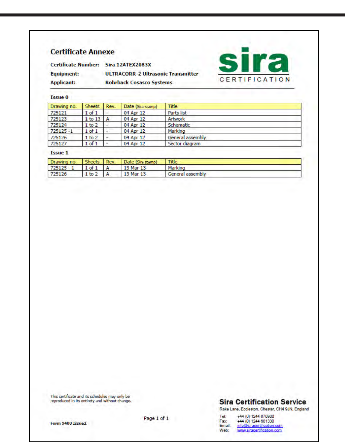
129
Bluetooth Suite
130
EC Type Examination Certificates
Ultracorr 2 Ultrasonic Transducer
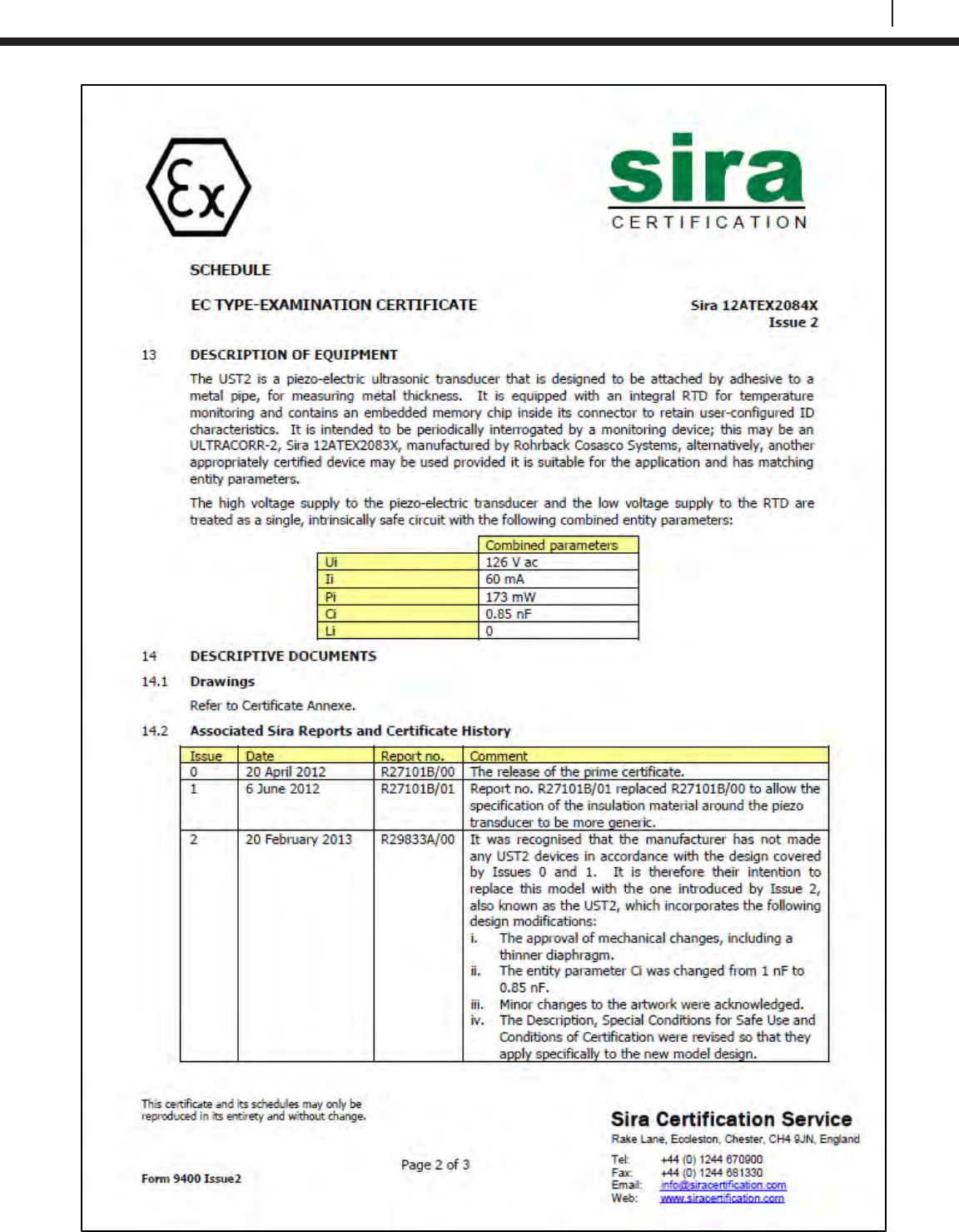
131
Bluetooth Suite
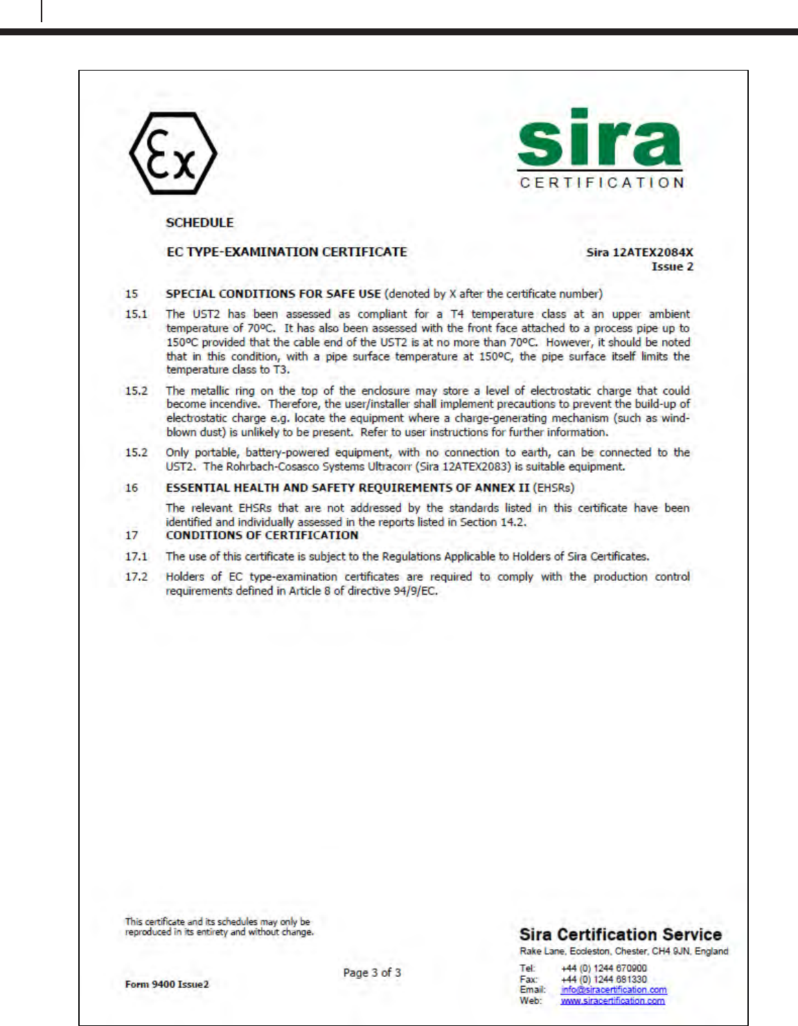
132
EC Type Examination Certificates
133
Bluetooth Suite
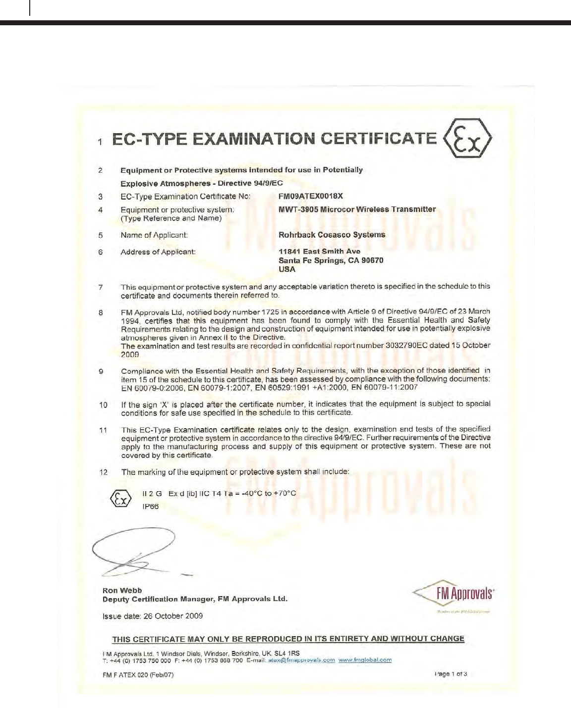
134
EC Type Examination Certificates
M-200
The M-200 uses the same certifications as the MWT-3905.
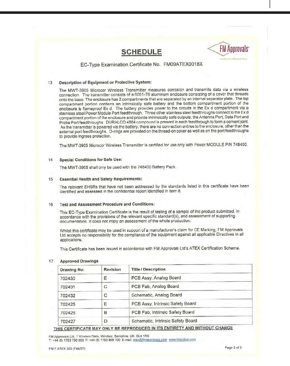
135
Bluetooth Suite
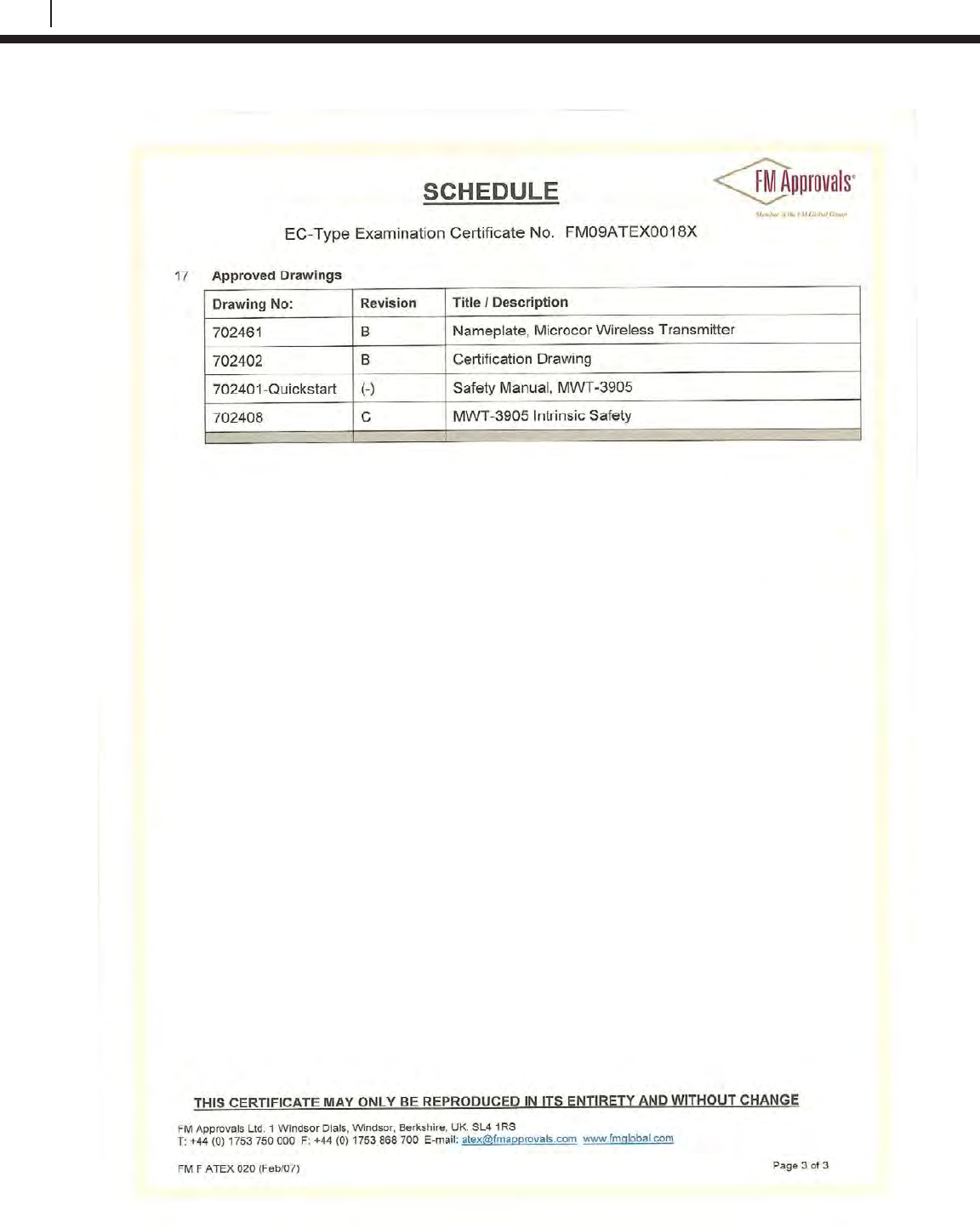
136
EC Type Examination Certificates
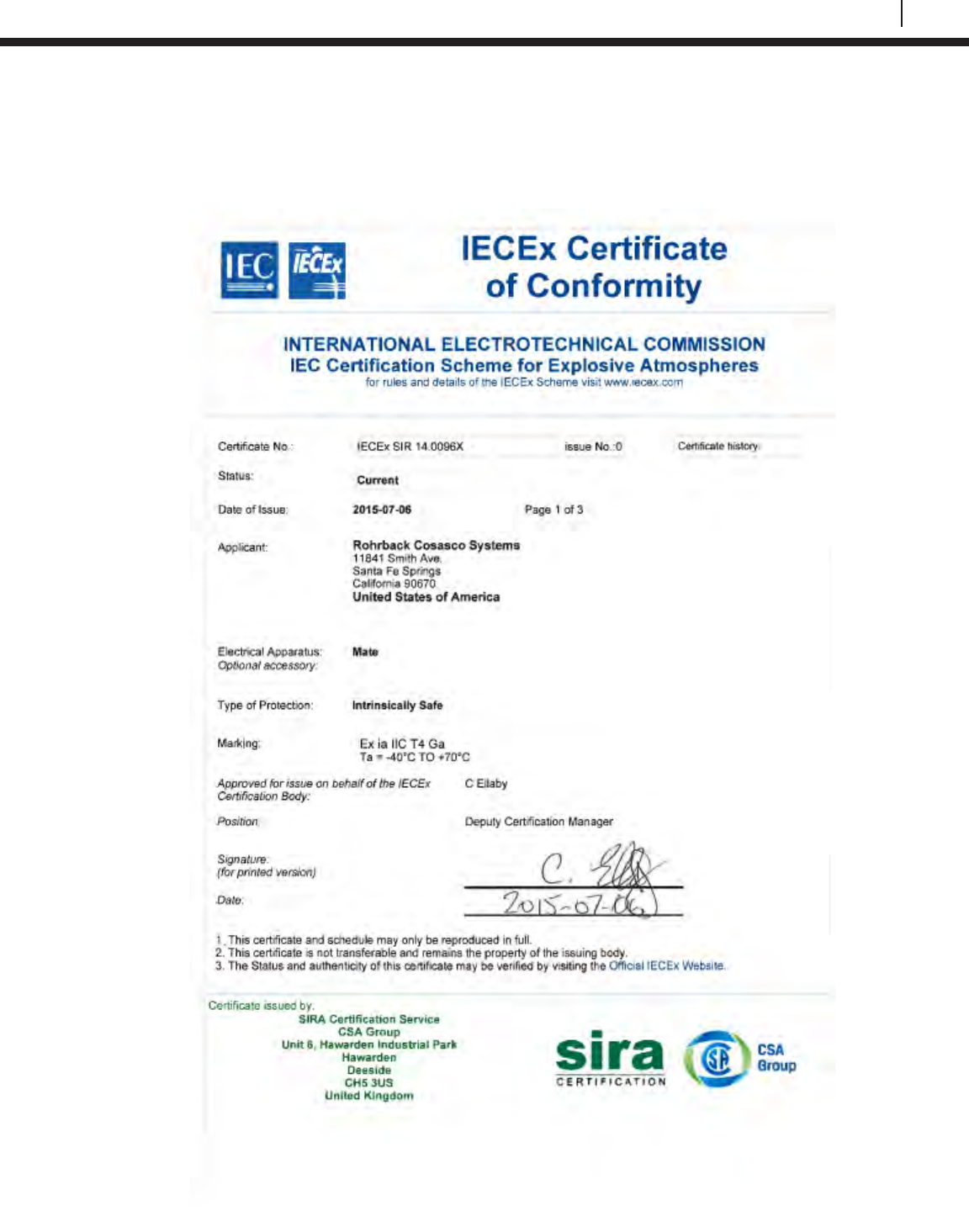
137
Bluetooth Suite
Appendix C
Certificates of Conformity
Transfer Unit
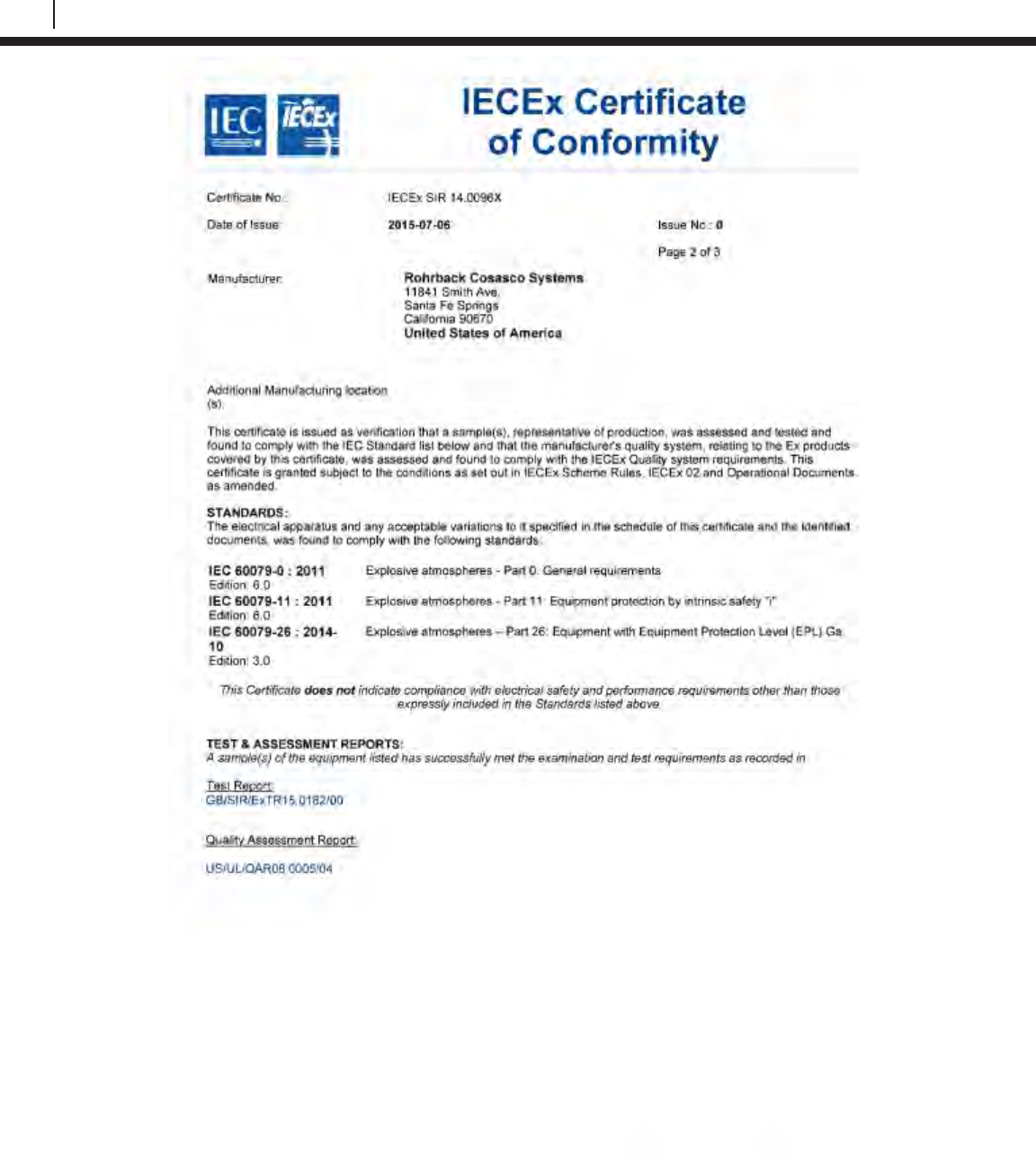
138
Certificates of Conformity
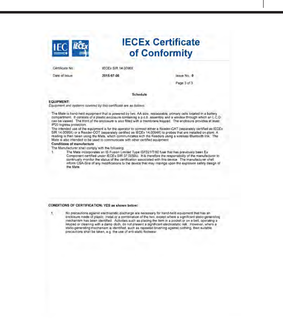
139
Bluetooth Suite
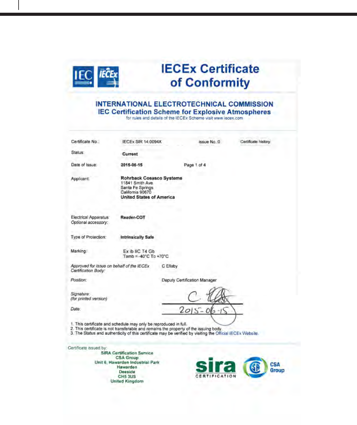
140
Certificates of Conformity
ER Probe Reader
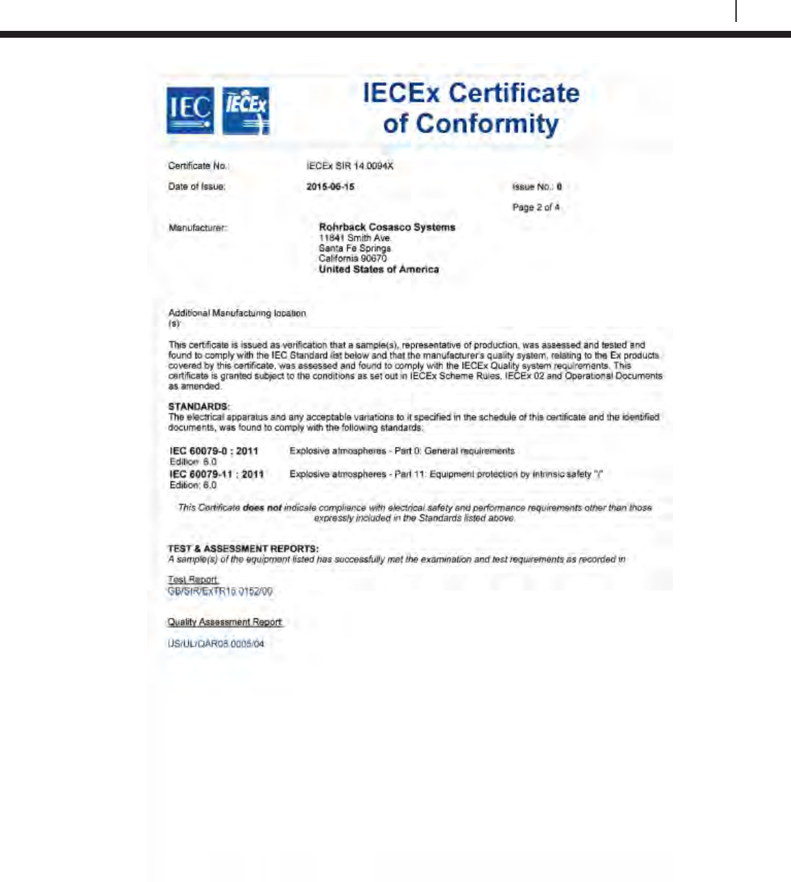
141
Bluetooth Suite
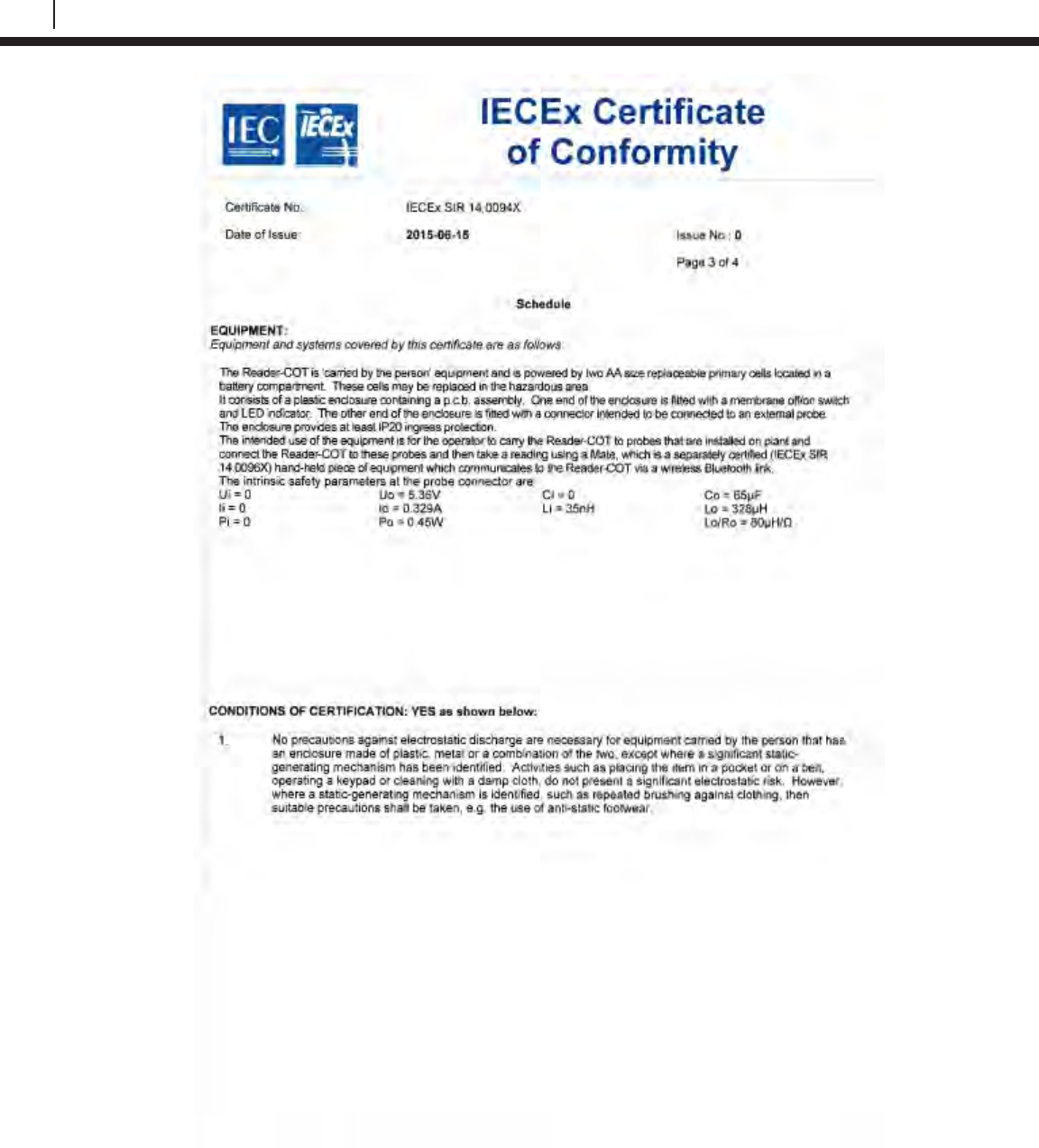
142
Certificates of Conformity
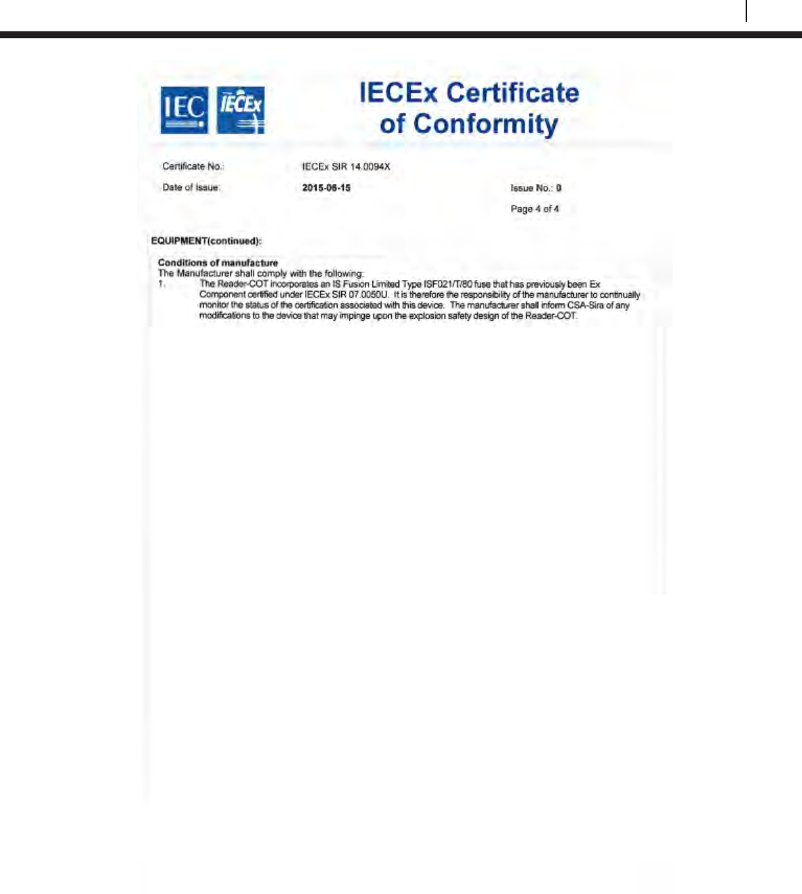
143
Bluetooth Suite
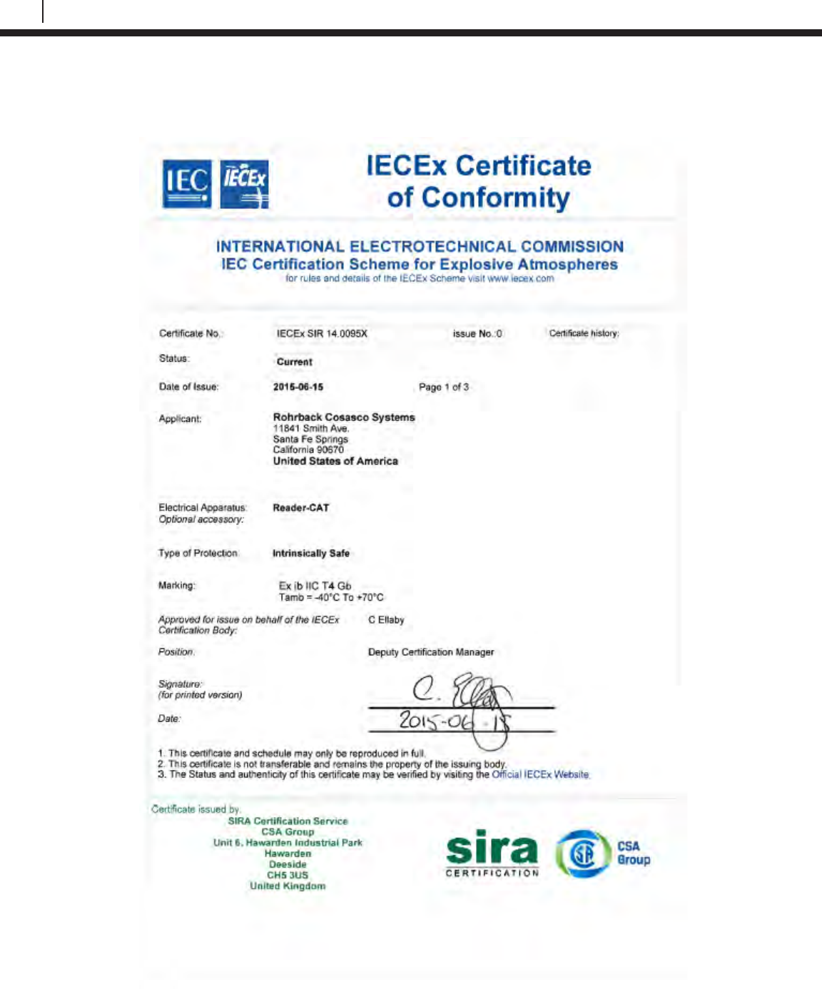
144
Certificates of Conformity
LPR Probe Reader
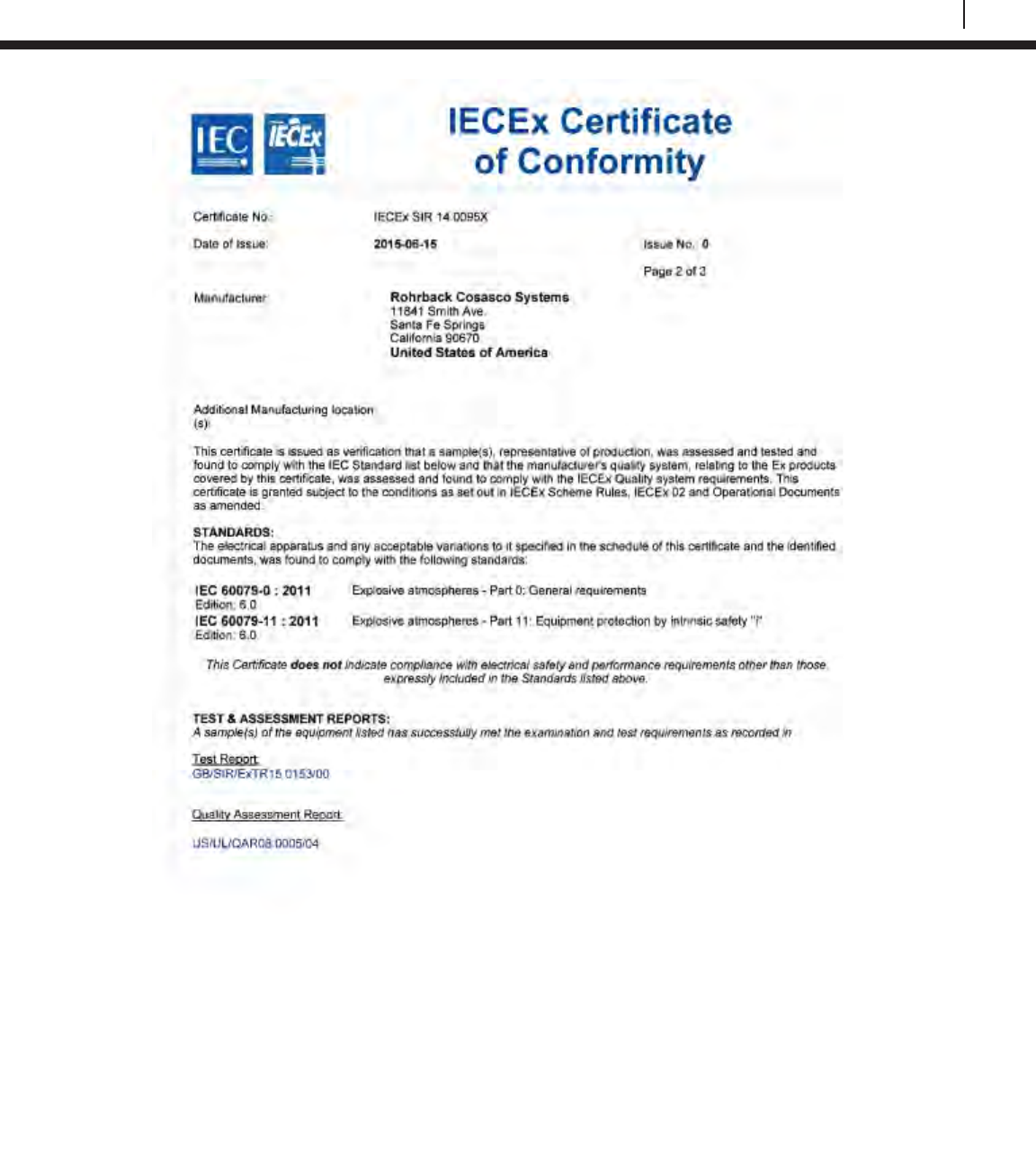
145
Bluetooth Suite
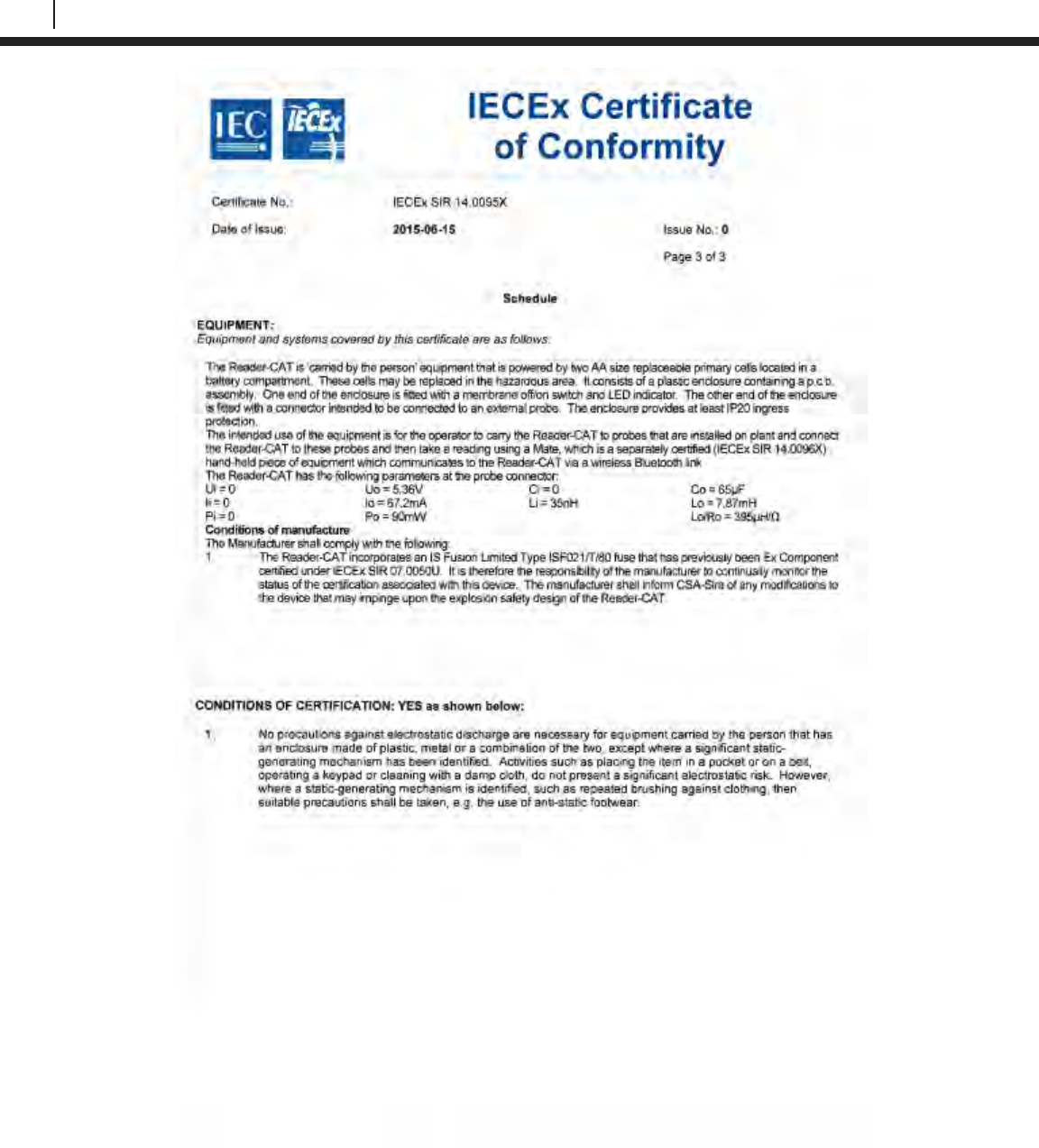
146
Certificates of Conformity
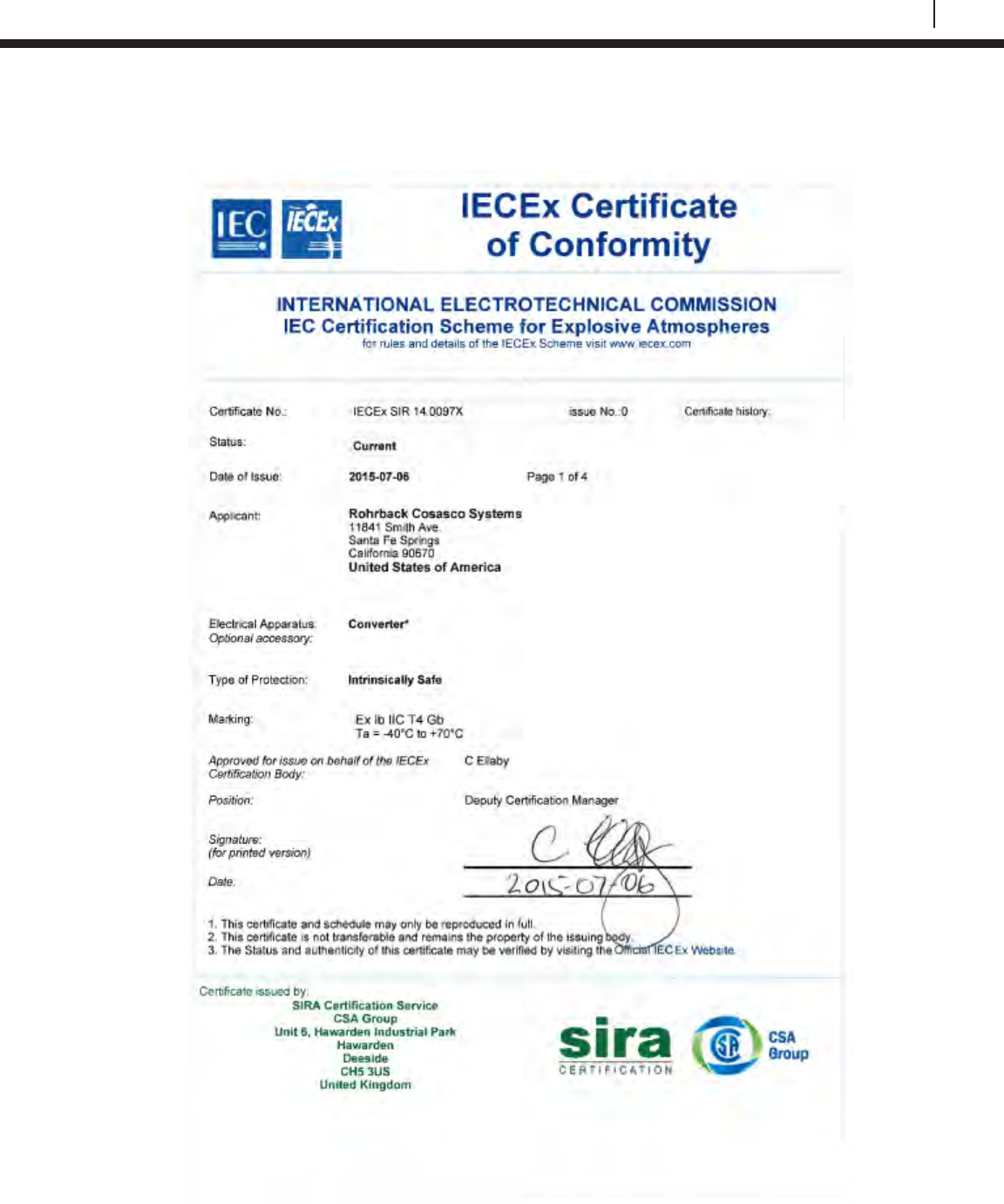
147
Bluetooth Suite
Legacy Converter
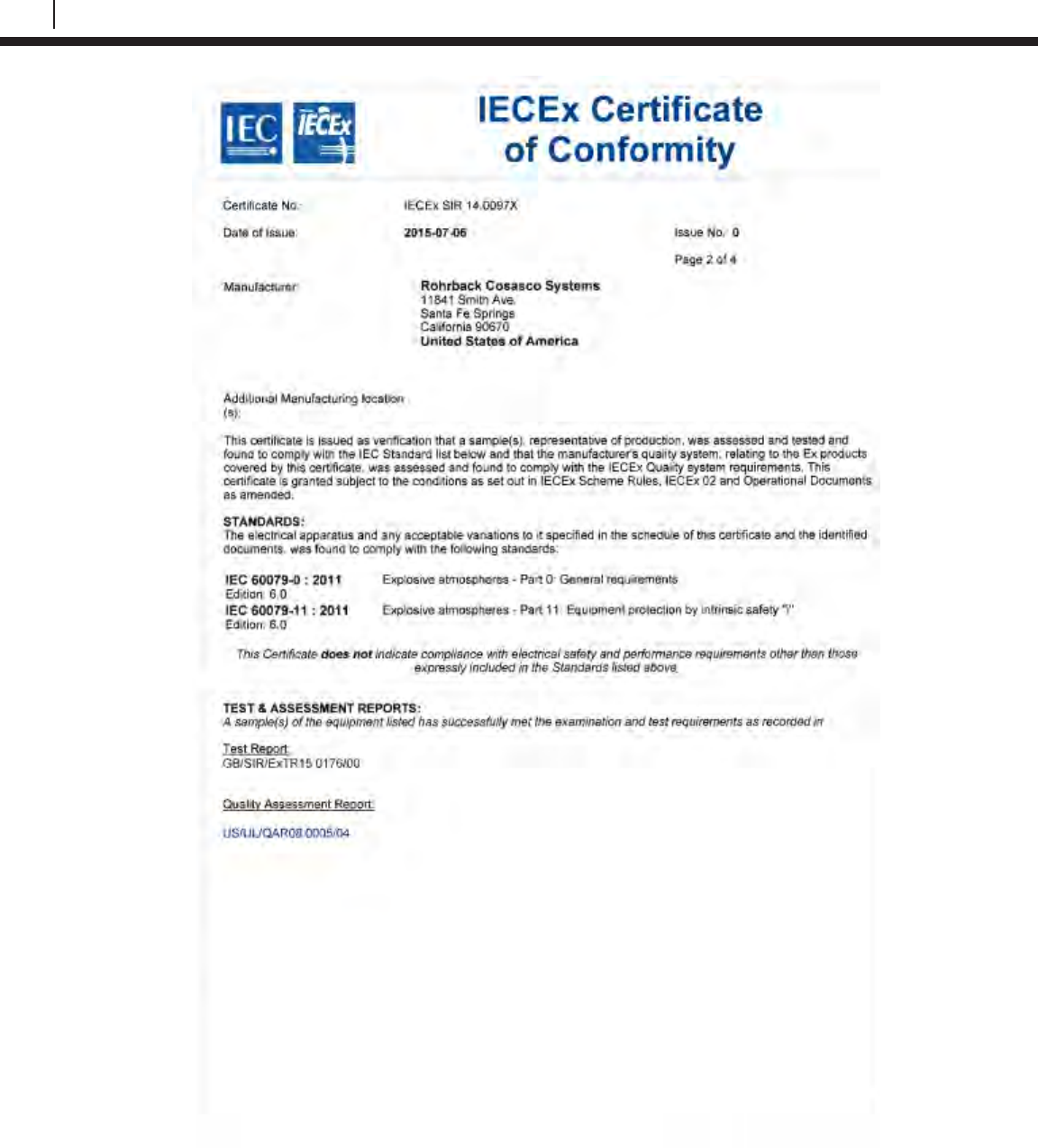
148
Certificates of Conformity
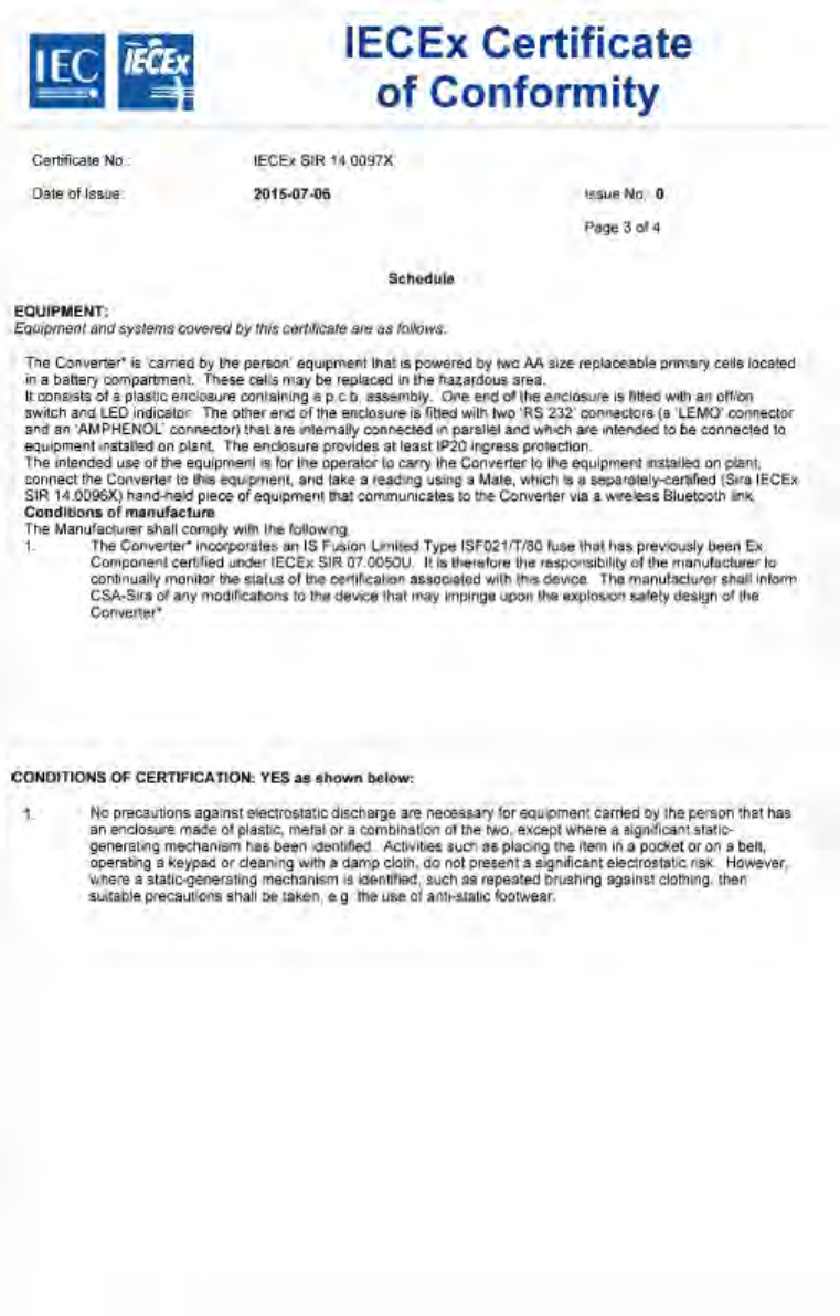
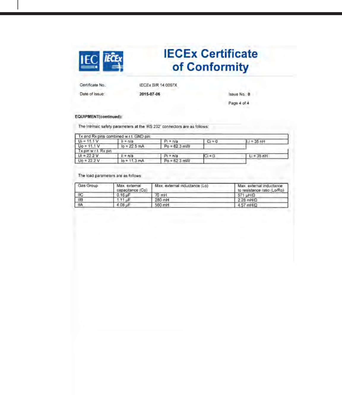
150
Certificates of Conformity
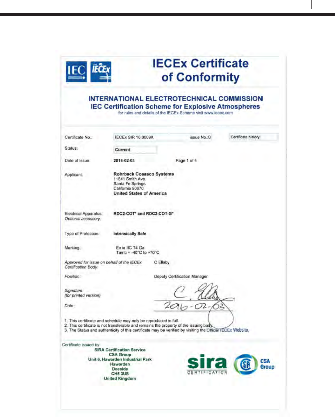
151
Bluetooth Suite
ER Datalogger
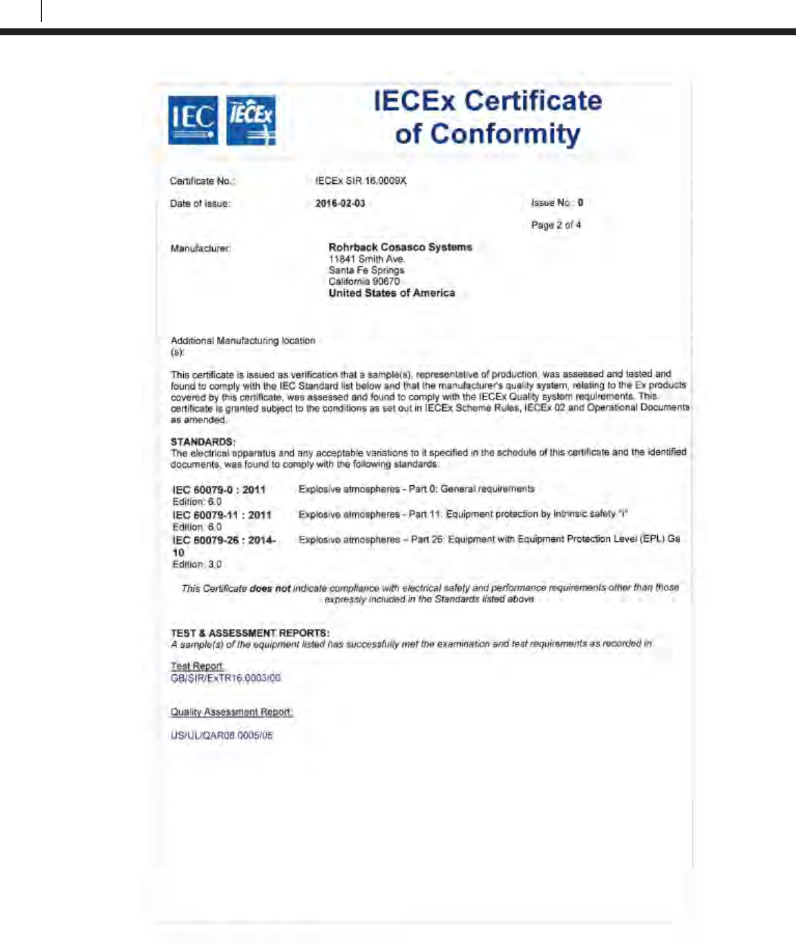
152
EC Type Examination Certificates
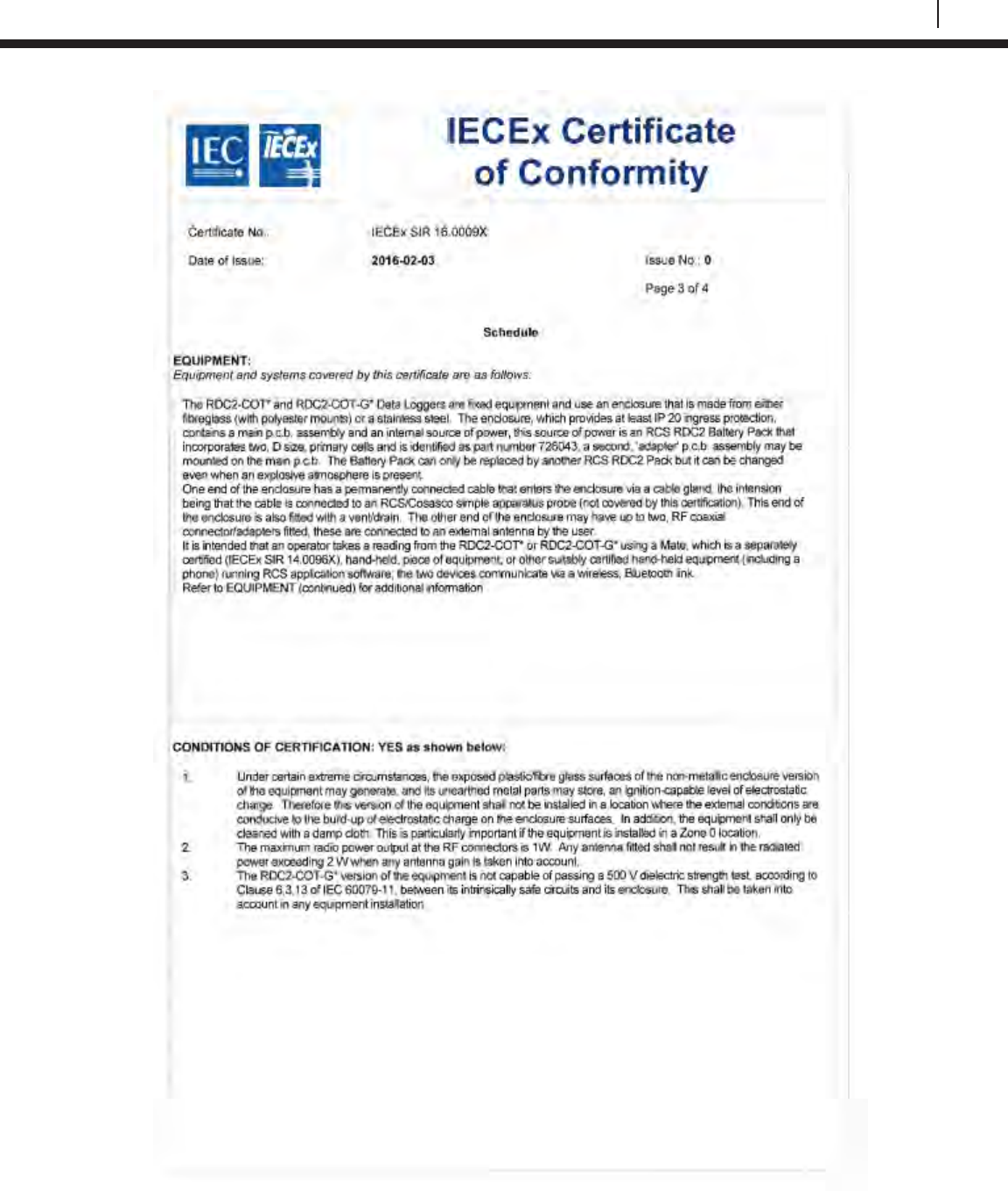
153
Bluetooth Suite
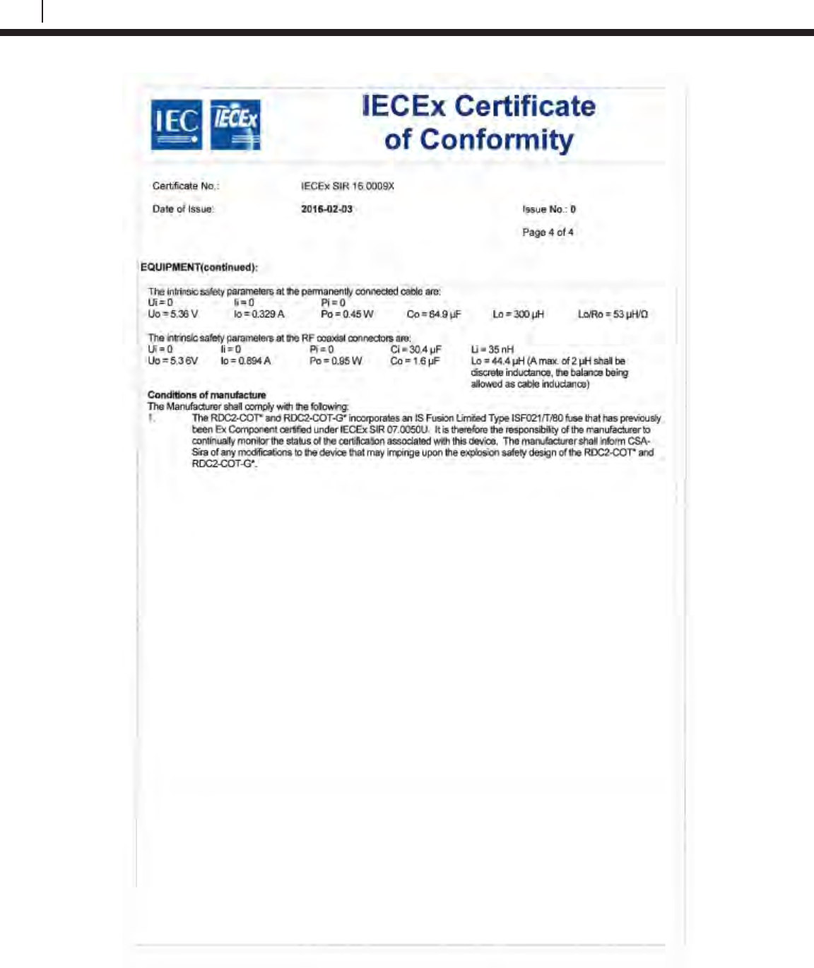
154
EC Type Examination Certificates
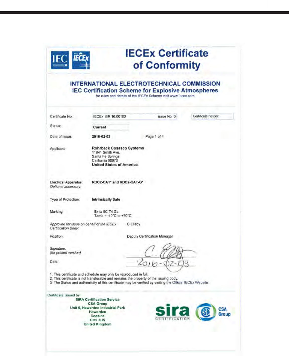
155
Bluetooth Suite
LPR Datalogger
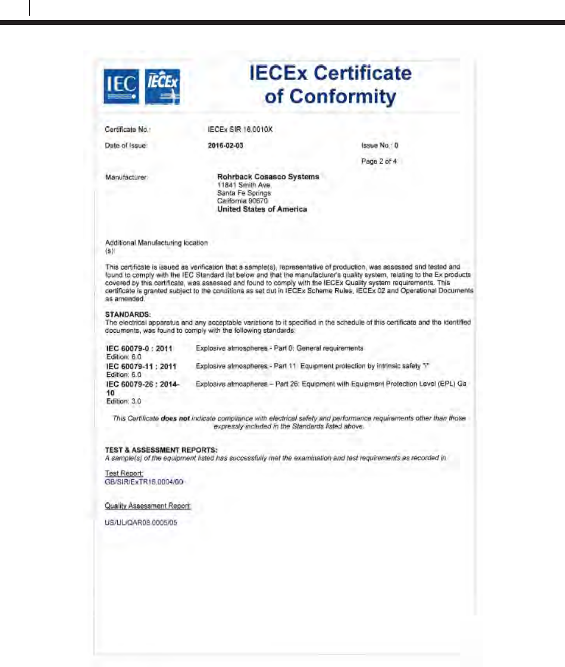
156
EC Type Examination Certificates
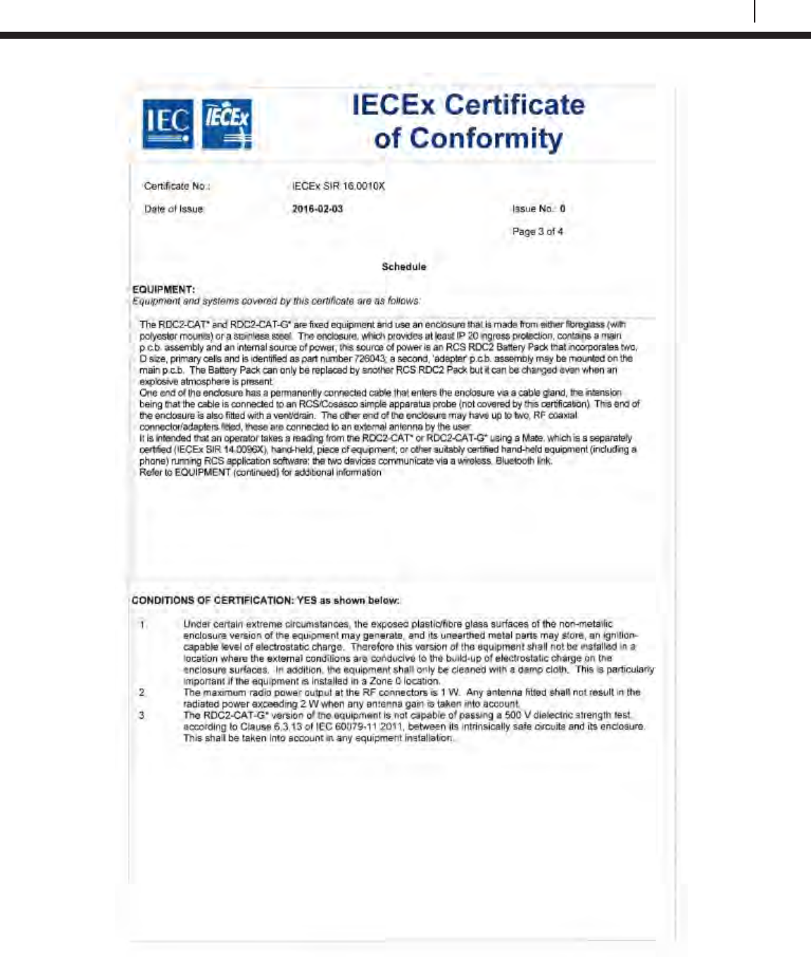
157
Bluetooth Suite
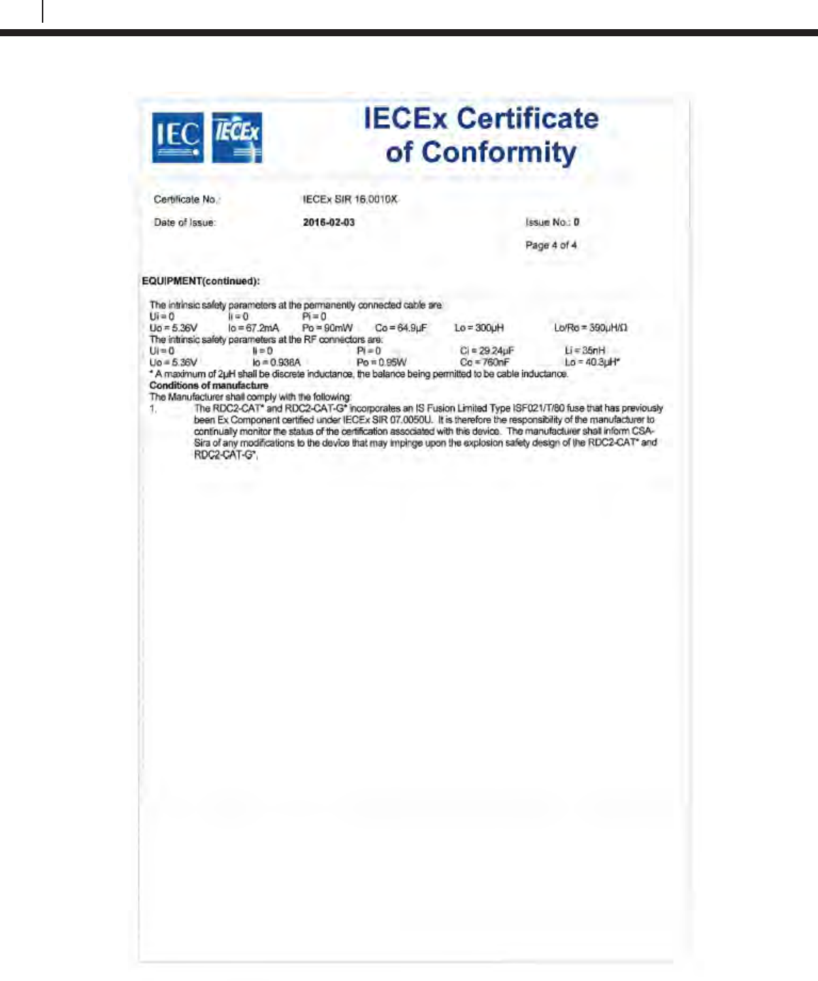
158
EC Type Examination Certificates
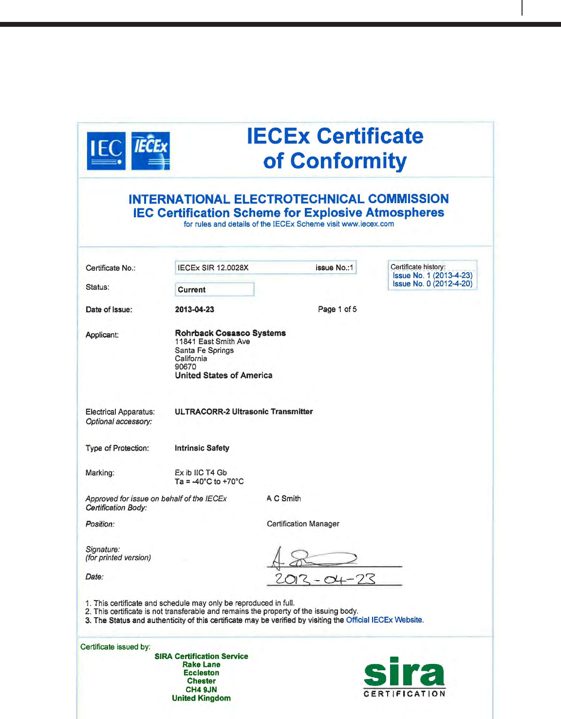
159
Bluetooth Suite
Ultracorr 2
Ultracorr 2 Ultrasonic Transmitter
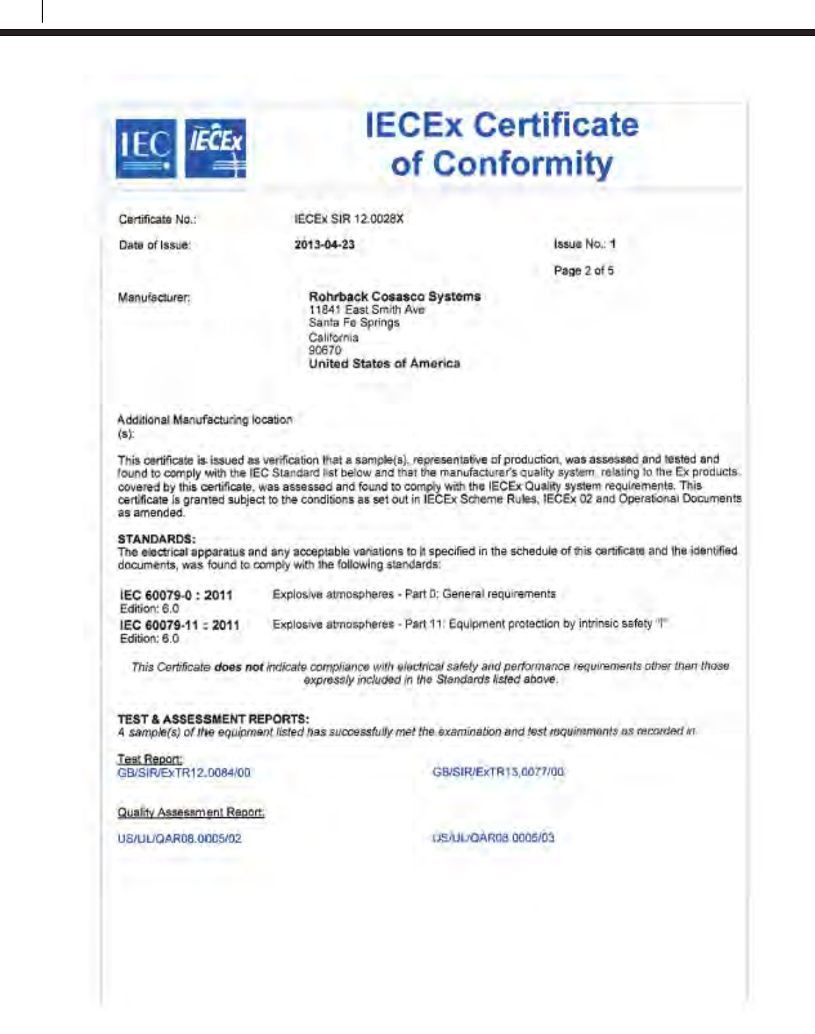
160
EC Type Examination Certificates
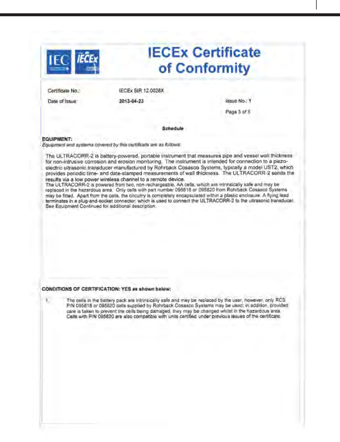
161
Bluetooth Suite
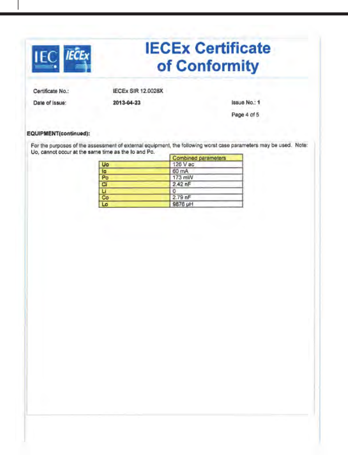
162
EC Type Examination Certificates
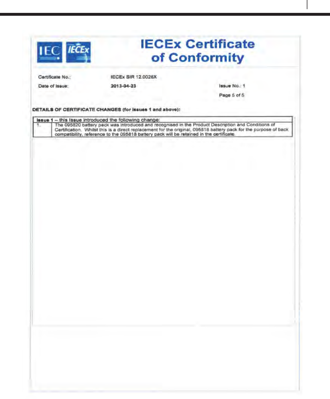
163
Bluetooth Suite
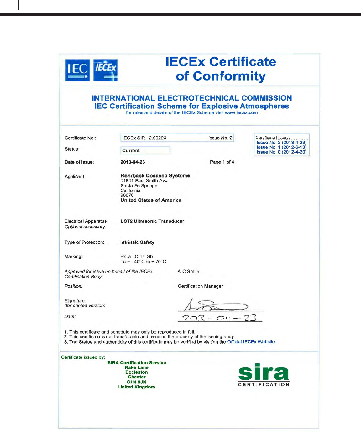
164
EC Type Examination Certificates
UST2 Ultrasonic Transducer
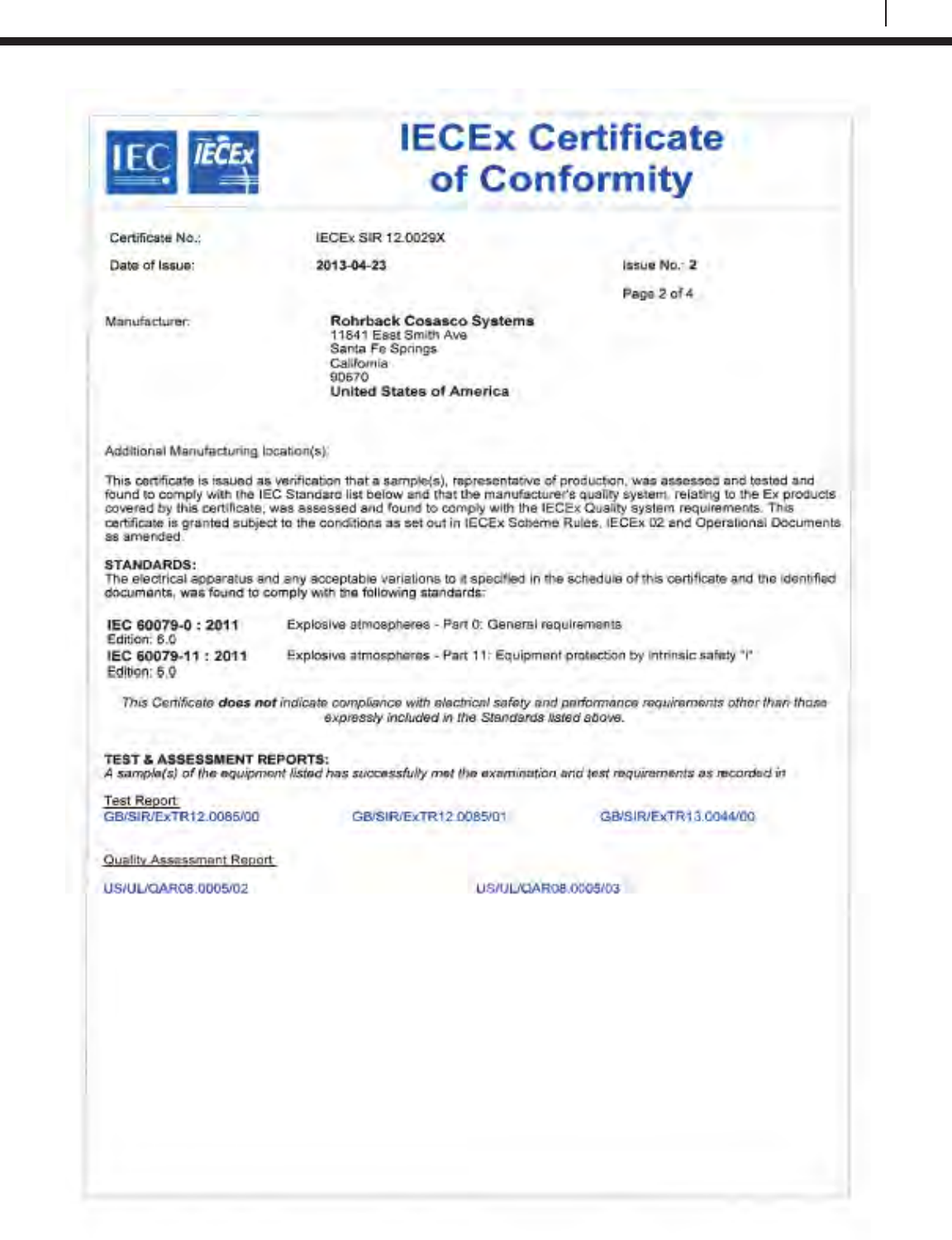
165
Bluetooth Suite
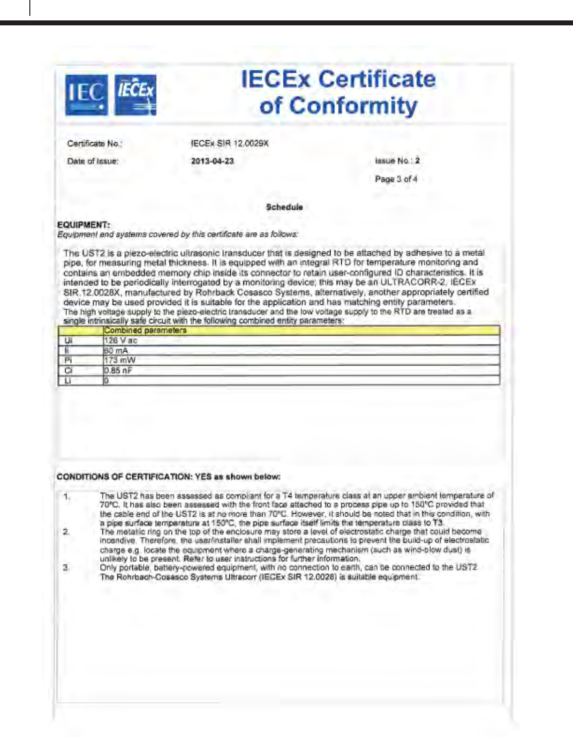
166
EC Type Examination Certificates
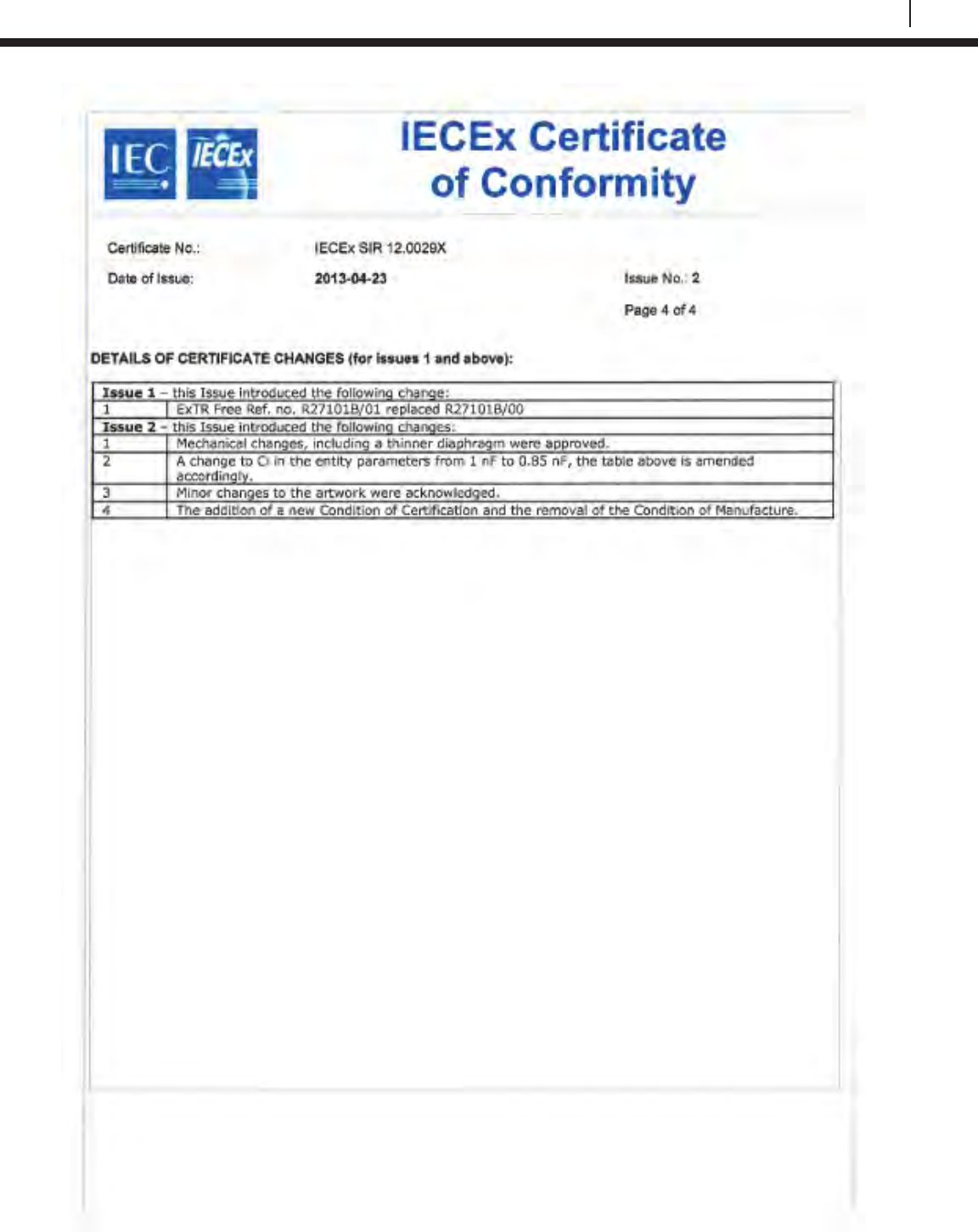
167
Bluetooth Suite
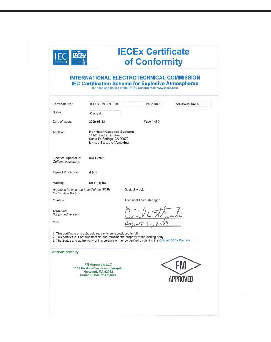
168
EC Type Examination Certificates
M-200
The M-200 uses the same certifications as the MWT-3905.
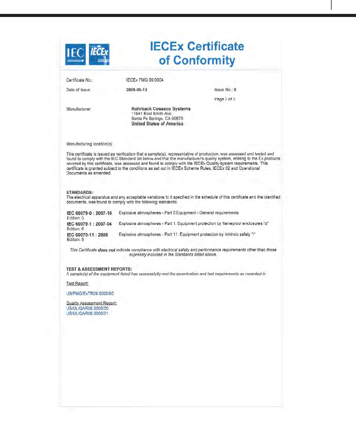
169
Bluetooth Suite
170
EC Type Examination Certificates
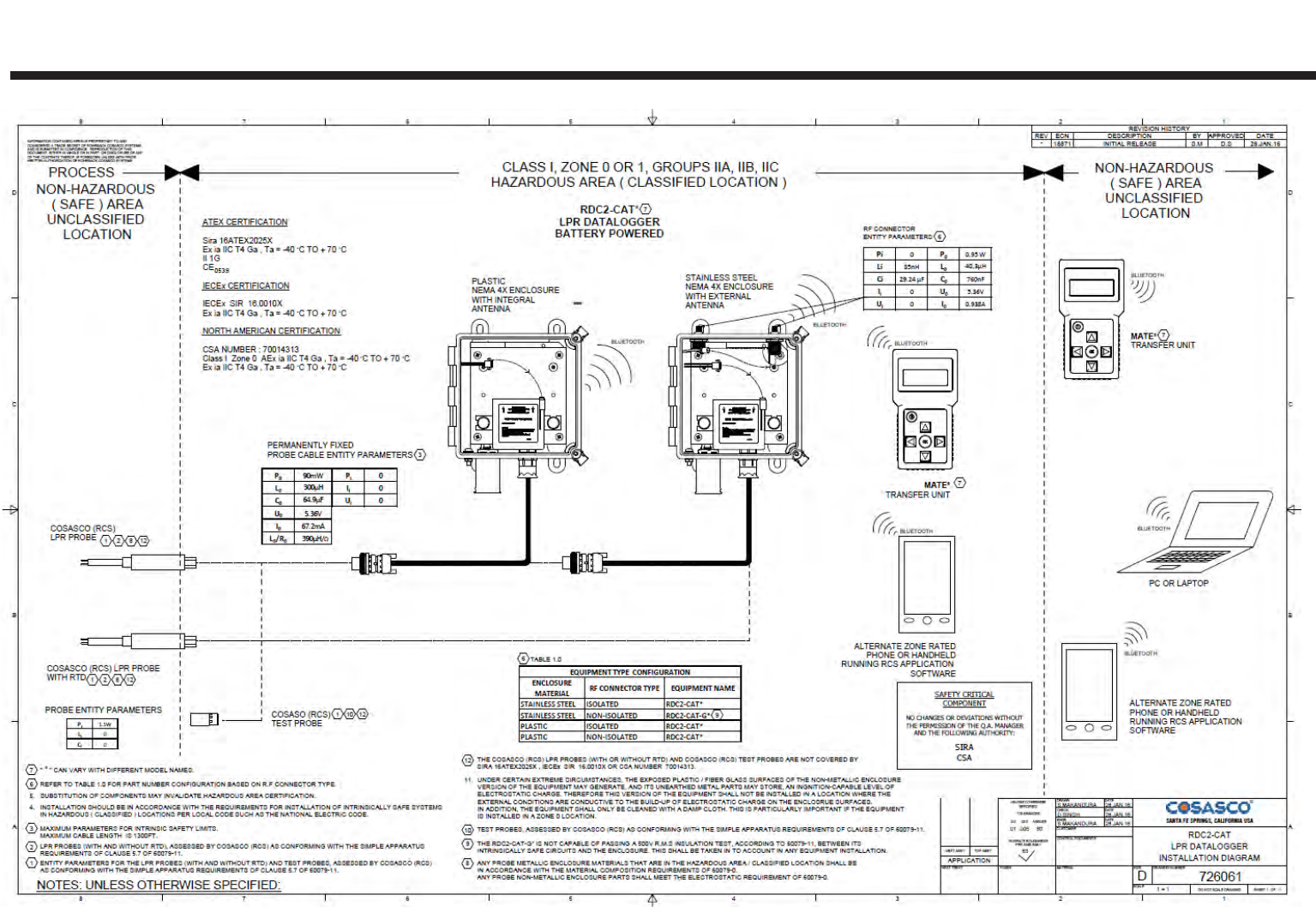
171
Appendix D
Drawing 726061

172
Drawing 726061
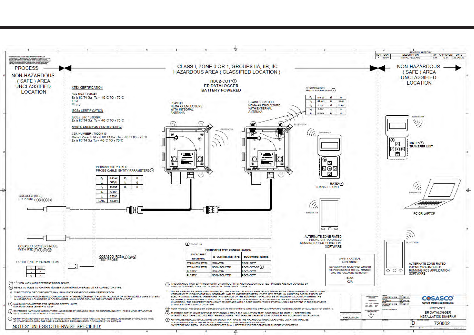
173
3
Appendix E
Drawing 726062

174
Drawing 726062
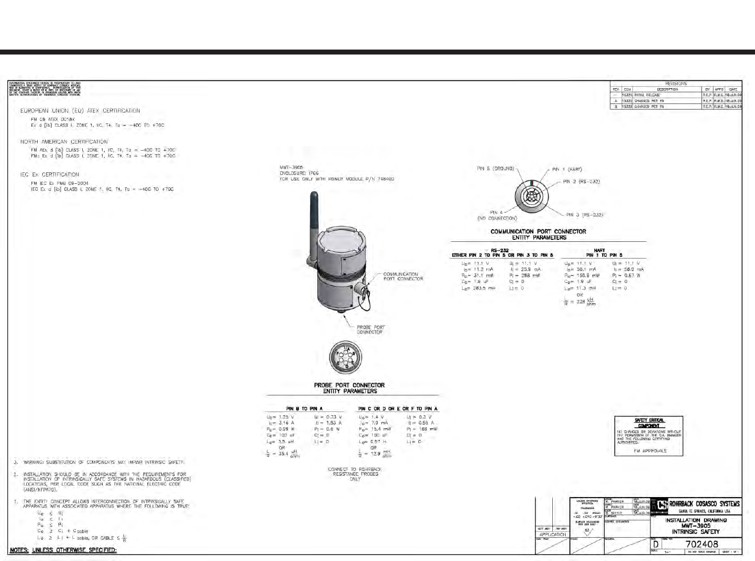
175
5
Appendix F
Drawing 702408

176
Drawing 702408